Настоящее руководство по эксплуатации (РЭ) предназначено для изучения конструкции, технических характеристик, правил эксплуатации контроллера (регулятора температуры) STC-1000 (в дальнейшем по тексту – «прибора»).
Перед установкой прибора в объект регулирования необходимо внимательно ознакомиться с настоящим РЭ.
Прибор рекомендуется эксплуатировать при температуре окружающего воздуха от минус 10 до плюс 60°С, относительной влажности (45–85)%.
1 Назначение.
Контроллер (регулятор температуры) STC-1000 предназначен для контроля и поддержания температуры объектов эксплуатации производственно-технического и бытового назначения. Прибор имеет два реле и может управлять одновременно нагревателем и холодильником.
В качестве датчика температуры используется NTC термистор длиной присоединительного кабеля 1 м. Датчик температуры входит в комплект поставки прибора.
2 Технические характеристики
2.1 Питание от сети перемененного тока напряжением 110 — 220В, 50 Гц.
2.2 Диапазон регулирования температуры (задания уставки) от минус 50 до плюс 99°С.
2.3 Разрешающая способность измерения температуры и задания уставки 0,1°С.
2.4 Возможность юстировки контроллера с дискретностью 0,1°С.
2.5 Диапазон задания температурного гистерезиса (разницы между температурой выключения и температурой включения реле) – от 0,3 до 10°С.
2.6 Время задержки включения реле «Cooling» (холодильника) – от 0 до 10 мин.
2.7 Максимальные коммутируемые токи реле – 8 А (максимальная мощность нагрузки – 1,5 кВт при 220 В 50Гц и cos j ³ 0,6).
- Габаритные размеры 75х35х85 мм.
3 Указания мер безопасности
3.1 Внимание! В приборе используется напряжение питания опасное для жизни человека.
3.2 Все подключения, а также техническое обслуживание и ремонт необходимо осуществлять при отключенной сети.
3.3 Установка, подключение прибора к сети и нагрузке должны производиться только квалифицированными специалистами, изучившими настоящее РЭ. Все соединения должны быть тщательно заизолированы. а токоведущие части закрыты, см. п.6.1.
3.4 Не допускается попадания влаги на контакты клеммника и внутрь прибора.
3.5 При эксплуатации и техническом обслуживании прибора необходимо соблюдать «Правила технической эксплуатации электроустановок потребителем» и «Правила техники безопасности при эксплуатации электроустановок».
3.6 При использовании прибора совместно с нагревателем — ТЭНом, тепловентилятором, конвектором и др. обязательно заземлите последний.
3.7 Если терморегулятор с нагревателем применяются для регулирования температуры во влажном помещении – погребе, подвале, теплице…, примите дополнительные меры безопасности: используйте кабели с надежной ПВХ-изоляцией, обязательно двойной, все кабели закрепите, (используйте кабель-каналы), кабель на полу поместите в защитную трубу.
Перед тем, как войти в помещение, отключайте терморегулятор от сети!
Помните, что влажное помещение представляет собой повышенную опасность!
4 Устройство и принцип действия
4.1 Конструктивно прибор выполнен в пластмассовом щитовом корпусе. Все подключения осуществляются через клеммник, расположенный с обратной стороны.
4.2 На передней панели управления и индикации расположены:
– цифровой светодиодный индикатор;
– индикаторы «Heat» и «Cool», отображающие включенные состояния реле нагрева и охлаждения соответственно;
– кнопки для управления и программирования: «Вкл» , «S», «Вверх», «ВНИЗ»
4.3 Программируемые параметры, отображаемые меню:
F1 – установка температуры выключения реле;
F2 – задание температурного гистерезиса (от 0,3°С до 10°С).;
F3 – установка времени задержки включения реле;
F4 – задание смещения характеристики по температуре (юстировка от –10°С до +10°С).
4.4 Принцип действия. В самом общем варианте применения прибор может управлять одновременно работой нагревателя и холодильника, например, нагревателем и вентилятором в погребе зимой и осенью. Допустим, установлены след параметры: Т выкл = 5°С; гистерезис = 2°С.
Вар.1: температура датчика (в объеме) ниже 3°С Прибор нагреет датчик (объем) до 5 град, после чего реле «Heat» отключит нагреватель. Температура опустится до 3 °С – реле включится и т.д. Вар 2: температура на датчике достигла 7 град. Прибор включит холодильник (реле «Cool»), температура опустится до 5°С – холодильник выключится…
5 Подготовка к работе
5.1 Подключите к прибору сетевой кабель, кабели нагрузок (нагреватель или охладитель или то и др. вместе) согласно схеме на верхней панели прибора. В общем варианте схема может выглядеть так: контакты 1, 5 и 7 соединены вместе; контакт 6 соединен с нагревателем, 8 – с холодильником; контакт 2 соединен с нагревателем и холодильником; к контакту 1 и 2 подключен сетевой кабель.
5.2 Включите прибор в сеть, при этом на индикаторе должна отобразиться текущая температура. Если прибор не включится, нажмите и удерживайте 4 сек кнопку (в дальнейшем кн.) «Вкл».
5.3 Программирование. Режим программирования предназначен для записи в энергонезависимую память прибора требуемых параметров. Заданные значения сохраняются при выключении питания.
Нажмите и удерживайте кн. «S» до появления символа F1. Отпустите и вновь нажмите кн. «S» и, не отпуская ее, установите кнопками «Вверх» –«Вниз» температуру выключения. Отпустите все кнопки и коротко нажмите кн. « Вкл» для запоминания установленного. значения.
Перейдите к установке следующего параметра — F2: нажмите кн. «S» и удерживайте ее до появления символа F1; отпустите кн. «S» и нажмите кн. «Вверх» — появится символ F2; нажмите кн. «S» и, удерживая ее, установите значение гистерезиса. Отпустите все кнопки и коротко нажмите кн. «Вкл».
Аналогично установите параметры F3 и F4. Вначале значение F4 можно установить равным 0.
Установленные температуру и гистерезис можно проверить, нажимая поочередно кнопки «Вверх» и «Вниз».
Появление на индикаторе символа ЕЕ, сопровождающегося звуковым сигналом, сигнализирует об обрыве датчика, символа НН – о выходе за пределы диапазона измерения. Если на индикаторе появится символ Er, нажмите на кн. «S» и удерживайте ее до перезагрузки контроллера. После этого надо будет повторить настойку прибора.
Нажав и удерживая 4 сек кн. «Вкл», контроллер можно выключить и включить.
6 Юстировка
Перед эксплуатацией прибора необходимо проверить точность показания температуры в выбранном диапазоне. Для юстировки следует использовать
измеритель температуры (термометр) класса точности не хуже 0,25. Датчик температуры прибора и контрольный датчик (термометр) помещают в термостатированный объем, выдерживают по времени не менее 30 мин, и
сверяют показания. При необходимости корректируют значения параметром F4.
Периодичность проведения данной процедуры — не реже одного раза в год.
7 Гарантийные обязательства
Гарантийный срок эксплуатации – 12 месяцев со дня продажи.
В случае выхода прибора в течение этого срока при соблюдении потребителем правил эксплуатации поставщик осуществляет его бесплатный ремонт или замену. Гарантии не распространяются на изделия с внешними повреждениями корпуса прибора или датчика, с вышедшими из строя компонентами регулятора в результате неправильного соединения токоведущих проводников, превышения допустимой мощности нагрузки или короткого замыкания.
Поставщик: ООО «Лионика». г. Новосибирск, ул. Русская, 39, оф 517, тел. 383(306-58-96).
Почтовый адрес: 630060, г. Новосибирск, ая 60, тел. (383)333-69-11, 8-913-461-24-58, e-mail: lionica2000@mail.ru https://.lionica.ru
Дата продажи_______
-
Драйверы
5
-
Руководства по ремонту
1
-
Инструкции по эксплуатации
18
Языки:

HP LaserJet 1000 инструкция по эксплуатации
(112 страниц)
- Языки:Русский
-
Тип:
PDF -
Размер:
1.68 MB -
Описание:
Лазерный принтер
Просмотр

HP LaserJet 1000 инструкция по эксплуатации
(104 страницы)
- Языки:Английский
-
Тип:
PDF -
Размер:
1.38 MB
Просмотр

HP LaserJet 1000 инструкция по эксплуатации
(104 страницы)
- Языки:Турецкий
-
Тип:
PDF -
Размер:
1.75 MB
Просмотр

HP LaserJet 1000 инструкция по эксплуатации
(108 страниц)
- Языки:Греческий
-
Тип:
PDF -
Размер:
1.68 MB
Просмотр

HP LaserJet 1000 инструкция по эксплуатации
(116 страниц)
- Языки:Тайский
-
Тип:
PDF -
Размер:
3.48 MB
Просмотр

HP LaserJet 1000 инструкция по эксплуатации
(102 страницы)
- Языки:Арабский
-
Тип:
PDF -
Размер:
2.15 MB
Просмотр

HP LaserJet 1000 инструкция по эксплуатации
(104 страницы)
- Языки:Шведский
-
Тип:
PDF -
Размер:
1.55 MB
Просмотр

HP LaserJet 1000 инструкция по эксплуатации
(108 страниц)
- Языки:Французский
-
Тип:
PDF -
Размер:
1.7 MB
Просмотр

HP LaserJet 1000 инструкция по эксплуатации
(108 страниц)
- Языки:Немецкий
-
Тип:
PDF -
Размер:
1.87 MB
Просмотр

HP LaserJet 1000 инструкция по эксплуатации
(104 страницы)
- Языки:Венгерский
-
Тип:
PDF -
Размер:
1.64 MB
Просмотр

HP LaserJet 1000 инструкция по эксплуатации
(104 страницы)
- Языки:Чешский
-
Тип:
PDF -
Размер:
2.03 MB
Просмотр

HP LaserJet 1000 инструкция по эксплуатации
(104 страницы)
- Языки:Словацкий
-
Тип:
PDF -
Размер:
2.05 MB
Просмотр

HP LaserJet 1000 инструкция по эксплуатации
(108 страниц)
- Языки:Нидерландский
-
Тип:
PDF -
Размер:
1.52 MB
Просмотр

HP LaserJet 1000 инструкция по эксплуатации
(104 страницы)
- Языки:Датский
-
Тип:
PDF -
Размер:
1.5 MB
Просмотр

HP LaserJet 1000 инструкция по эксплуатации
(103 страницы)
- Языки:Иврит
-
Тип:
PDF -
Размер:
3.01 MB
Просмотр

HP LaserJet 1000 инструкция по эксплуатации
(108 страниц)
- Языки:Польский
-
Тип:
PDF -
Размер:
1.69 MB
Просмотр

HP LaserJet 1000 инструкция по эксплуатации
(104 страницы)
- Языки:Финский
-
Тип:
PDF -
Размер:
1.71 MB
Просмотр

HP LaserJet 1000 инструкция по эксплуатации
(104 страницы)
- Языки:Корейский
-
Тип:
PDF -
Размер:
1.78 MB
Просмотр
На NoDevice можно скачать инструкцию по эксплуатации для HP LaserJet 1000. Руководство пользователя необходимо для ознакомления с правилами установки и эксплуатации HP LaserJet 1000. Инструкции по использованию помогут правильно настроить HP LaserJet 1000, исправить ошибки и выявить неполадки.
- Manuals
- Brands
- YASKAWA Manuals
- Controller
- A1000 Series
Manuals and User Guides for YASKAWA A1000 Series. We have 16 YASKAWA A1000 Series manuals available for free PDF download: Technical Manual, Quick Start Manual, Installation Manual, Product Replacement Manual, Manual, Setup
YASKAWA A1000 Series Technical Manual (544 pages)
High Performance Vector Control Drive Models: 200 V Class: 0.4 to 110 kW 400 V Class: 0.4 to 355 kW
Brand: YASKAWA
|
Category: Controller
|
Size: 56.82 MB
Table of Contents
-
Table of Contents
5
-
Quick Reference
3
-
Table of Contents
5
-
-
I.1 Preface
16
-
Applicable Documentation
16
-
Symbols
16
-
Terms and Abbreviations
16
-
-
I.2 General Safety
17
-
Supplemental Safety Information
17
-
Safety Messages
18
-
Application Notes
19
-
Notes on Motor Operation
21
-
Applications with Specialized Motors
22
-
Drive Label Warnings
24
-
Warranty Information
24
-
-
-
Receiving
25
-
Section Safety
26
-
General Description
27
-
A1000 Model Selection
27
-
Control Mode Selection
28
-
-
Model Number and Nameplate Check
29
-
Nameplate
29
-
-
Drive Models and Enclosure Types
31
-
Component Names
32
-
IP20/NEMA Type 1 Enclosure
32
-
IP00 Enclosure
32
-
Front Views
35
-
-
Mechanical Installation
37
-
Section Safety
38
-
Installation Environment
40
-
-
2 Mechanical Installation
40
-
Installation Orientation and Spacing
40
-
Digital Operator Remote Usage
42
-
Exterior and Mounting Dimensions
46
-
-
-
Electrical Installation
51
-
Section Safety
52
-
Standard Connection Diagram
54
-
Main Circuit Connection Diagram
56
-
Three-Phase 200 V Class (CIMR-A 2A0169 to
56
-
Three-Phase 400 V Class (CIMR-A 4A0088 to 0675)
56
-
Terminal Block Configuration
57
-
Terminal Cover
59
-
-
CIMR-A 2A0004 to 0081, 4A0002 to 0044 (IP20/NEMA Type 1 Enclosure)
59
-
CIMR-A 2A0110 to 0415, 4A0058 to 0675 (IP00 Enclosure)
60
-
Digital Operator and
61
-
-
Removing/Reattaching the Digital Operator
61
-
Removing/Reattaching the Front Cover
61
-
Top Protective Cover
64
-
Removing the Top Protective Cover
64
-
Reattaching the Top Protective Cover
64
-
-
Main Circuit Wiring
65
-
-
Main Circuit Terminal Functions
65
-
Protecting Main Circuit Terminals
65
-
Wire Gauges and Tightening Torque
66
-
Main Circuit Terminal and Motor Wiring
70
-
Control Circuit Wiring
72
-
-
Control Circuit Connection Diagram
72
-
Control Circuit Terminal Block Functions
72
-
Terminal Configuration
73
-
Wiring the Control Circuit Terminal
74
-
Switches and Jumpers on the Terminal Board
76
-
Control I/O Connections
77
-
-
Sinking/Sourcing Mode Selection for Safe Disable Inputs
77
-
Sinking/Sourcing Mode Switch for Digital Inputs
77
-
Using the Pulse Train Output
78
-
Terminal A2 Input Signal Selection
79
-
Terminal A3 Analog/Ptc Input Selection
79
-
Terminal AM/FM Signal Selection
79
-
Memobus/Modbus Termination
80
-
Connect to a Pc
81
-
External Interlock
82
-
-
Drive Ready
82
-
Wiring Checklist
83
-
-
-
Start-Up Programming & Operation
85
-
Section Safety
86
-
Keys and Displays
87
-
Using the Digital Operator
87
-
LCD Display
88
-
ALARM (ALM) LED Displays
89
-
LO/RE LED and RUN LED Indications
89
-
Menu Structure for Digital Operator
90
-
The Drive and Programming Modes
91
-
Navigating the Drive and Programming Modes
91
-
Changing Parameter Settings or Values
92
-
Verifying Parameter Changes: Verify Menu
94
-
Simplified Setup Using the Setup Group
95
-
Switching between LOCAL and REMOTE
96
-
Start-Up Flowcharts
98
-
Flowchart A: Basic Start-Up and Motor Tuning
98
-
Subchart A-1: Simple Motor Setup Using V/F Control
99
-
Subchart A-2: High Performance Operation Using OLV or CLV
100
-
Subchart A-3: Operation with Permanent Magnet Motors
101
-
Powering up the Drive
102
-
Powering up the Drive and Operation Status Display
102
-
Application Selection
103
-
Setting 1: Water Supply Pump Application
103
-
Setting 2: Conveyor Application
103
-
Setting 3: Exhaust Fan Application
104
-
Setting 4: HVAC Fan Application
104
-
Setting 5: Compressor Application
105
-
Setting 6: Hoist Application
105
-
Notes on Controlling the Brake When Using the Hoist Application Preset
106
-
Setting 7: Traveling Application
108
-
Auto-Tuning
109
-
Types of Auto-Tuning
109
-
Before Auto-Tuning the Drive
111
-
Auto-Tuning Interruption and Fault Codes
112
-
Auto-Tuning Operation Example
112
-
Parameter Settings During Induction Motor Auto-Tuning: T1
114
-
Parameter Settings During PM Motor Auto-Tuning: T2
116
-
Parameter Settings During Inertia and Speed Control Loop Auto-Tuning: T3
119
-
No-Load Operation Test Run
121
-
Test Run with Load Connected
123
-
Test Run with the Load Connected
123
-
Verifying Parameter Settings and Backing up Changes
124
-
Backing up Parameter Values: O2-03
124
-
Parameter Access Level: A1-01
124
-
Password Settings: A1-04, A1-05
124
-
Copy Function
125
-
Test Run Checklist
126
-
-
-
Parameter Details
129
-
A1: Initialization
130
-
A: Initialization
130
-
A2: User Parameters
135
-
B1: Operation Mode Selection
136
-
B: Application
136
-
B2: DC Injection Braking and Short Circuit Braking
144
-
B3: Speed Search
146
-
B4: Delay Timers
151
-
B5: PID Control
152
-
B6: Dwell Function
161
-
B7: Droop Control (CLV, CLV/PM)
162
-
B8: Energy Saving
163
-
B9: Zero Servo
164
-
C1: Acceleration and Deceleration Times
165
-
C: Tuning
165
-
C2: S-Curve Characteristics
167
-
C3: Slip Compensation
167
-
C4: Torque Compensation
170
-
C5: Automatic Speed Regulator (ASR)
171
-
C6: Carrier Frequency
177
-
D: Reference Settings
180
-
-
D1: Frequency Reference
180
-
D2: Frequency Upper/Lower Limits
182
-
D3: Jump Frequency
182
-
D4: Frequency Reference Hold and Up/Down 2 Function
183
-
D5: Torque Control
188
-
D6: Field Weakening and Field Forcing
192
-
D7: Offset Frequency
193
-
E: Motor Parameters
194
-
-
E1: V/F Pattern for Motor 1
194
-
E2: Motor 1 Parameters
198
-
E3: V/F Pattern for Motor 2
201
-
E4: Motor 2 Parameters
202
-
E5: PM Motor Settings
204
-
F: Option Settings
206
-
-
F1: PG Speed Control Card Settings
206
-
F2: Analog Input Card Settings
209
-
F3: Digital Input Card Settings
209
-
F4: Analog Monitor Card Settings
210
-
F5: Digital Output Card Settings
211
-
F6: Communication Option Card
211
-
Canopen Parameters
213
-
CC-Link Parameters
213
-
Devicenet Parameters
213
-
H: Terminal Functions
214
-
-
MECHATROLINK Parameters
213
-
PROFIBUS-DP Parameters
213
-
H1: Multi-Function Digital Inputs
214
-
H2: Multi-Function Digital Outputs
224
-
H3: Multi-Function Analog Inputs
234
-
H4: Multi-Function Analog Outputs
239
-
H5: Memobus/Modbus Serial Communication
241
-
H6: Pulse Train Input/Output
241
-
L: Protection Functions
244
-
-
L1: Motor Protection
244
-
L2: Momentary Power Loss Ride-Thru
249
-
L3: Stall Prevention
255
-
L4: Speed Detection
262
-
L5: Fault Restart
263
-
L6: Torque Detection
264
-
L7: Torque Limit
267
-
L8: Drive Protection
269
-
N: Special Adjustments
275
-
-
N1: Hunting Prevention
275
-
N2: Speed Feedback Detection Control (AFR) Tuning
276
-
N3: High Slip Braking (HSB) and Overexcitation Braking
276
-
N5: Feed Forward Control
279
-
N6: Online Tuning
280
-
N8: PM Motor Control Tuning
281
-
O: Operator Related Settings
284
-
-
O1: Digital Operator Display Selection
284
-
O2: Digital Operator Keypad Functions
285
-
O3: Copy Function
287
-
O4: Maintenance Monitor Settings
288
-
Q: Driveworksez Parameters
289
-
R: Driveworksez Connection Parameters
289
-
T: Motor Tuning
290
-
U: Monitor Parameters
291
-
-
U1: Operation Status Monitors
291
-
U2: Fault Trace
291
-
U3: Fault History
291
-
U4: Maintenance Monitors
291
-
U5: PID Monitors
291
-
U6: Operation Status Monitors
291
-
U8: Driveworksez Monitors
292
-
-
Troubleshooting
293
-
Section Safety
294
-
Fine-Tuning Open Loop Vector Control
296
-
Fine-Tuning V/F Control and V/F Control with PG
296
-
Motor Performance Fine-Tuning
296
-
Fine-Tuning Closed Loop Vector Control
297
-
Fine-Tuning Open Loop Vector Control for PM Motors
297
-
Fine-Tuning Advanced Open Loop Vector Control for PM Motors
298
-
Fine-Tuning Closed Loop Vector Control for PM Motors
298
-
Parameters to Minimize Motor Hunting and Oscillation
299
-
Drive Alarms, Faults, and Errors
300
-
Types of Alarms, Faults, and Errors
300
-
-
Alarm and Error Displays
301
-
Fault Detection
306
-
-
Fault Displays, Causes, and Possible Solutions
306
-
Alarm Detection
319
-
-
Alarm Codes, Causes, and Possible Solutions
319
-
Operator Programming Errors
325
-
-
Ope Codes, Causes, and Possible Solutions
325
-
Auto-Tuning Fault Detection
328
-
-
Auto-Tuning Codes, Causes, and Possible Solutions
328
-
Copy Function Related Displays
332
-
-
Tasks, Errors, and Troubleshooting
332
-
Diagnosing and Resetting Faults
334
-
-
Fault Occurs Simultaneously with Power Loss
334
-
If the Drive Still Has Power after a Fault Occurs
334
-
Viewing Fault Trace Data after Fault
334
-
Fault Reset Methods
335
-
Troubleshooting Without Fault Display
336
-
Common Problems
336
-
Cannot Change Parameter Settings
336
-
Motor Does Not Rotate Properly after Pressing RUN Button or after
336
-
Entering External Run Command
337
-
Motor Is too Hot
338
-
Drive Does Not Allow Selection the Desired Auto-Tuning Mode
338
-
Ope02 Error Occurs When Lowering the Motor Rated Current Setting
338
-
Motor Stalls During Acceleration or Acceleration Time Is too Long
338
-
Reference Command
339
-
Excessive Motor Oscillation and Erratic Rotation
339
-
Deceleration Takes Longer than Expected with Dynamic Braking Enabled
339
-
Load Falls When Brake Is Applied (Hoist-Type Applications)
339
-
Noise from Drive or Output Lines When the Drive Is Powered on
340
-
Earth Leakage Circuit Breaker (ELCB) Trips During Run
340
-
Connected Machinery Vibrates When Motor Rotates
340
-
PID Output Fault
340
-
Insufficient Starting Torque
340
-
Output Frequency Is Not as High as Frequency Reference
341
-
Buzzing Sound from Motor at 2 Khz
341
-
Unstable Motor Speed When Using PM
341
-
Motor Does Not Restart after Power Loss
341
-
-
Advertisement
YASKAWA A1000 Series Technical Manual (628 pages)
High Performance Vector Control Drive
Type: CIMR-A series
Models: 200 V Class: 0.55 to 110 kW,
400 V Class: 0.55 to 630 kW
Brand: YASKAWA
|
Category: Controller
|
Size: 55.44 MB
Table of Contents
-
Table of Contents
5
-
YASKAWA ELECTRIC SIEP C710616 27G YASKAWA AC Drive A1000 Technical Manual
13
-
I.1 Preface
15
-
Applicable Documentation
16
-
I.2 General Safety
19
-
Application Notes
21
-
Notes on Motor Operation
23
-
Applications with Specialized Motors
24
-
Drive Label Warnings
25
-
Warranty Information
26
-
-
-
Receiving
27
-
Section Safety
28
-
General Description
29
-
General Description
31
-
Model Number and Nameplate Check
32
-
Drive Models and Enclosure Types
33
-
Drive Models and Enclosure Types
34
-
Component Names
35
-
Component Names
37
-
IP00 Enclosure
38
-
Front Views
42
-
2 Mechanical Installation
43
-
Section Safety
44
-
Mechanical Installation
48
-
Digital Operator Remote Usage
50
-
Exterior and Mounting Dimensions
52
-
-
-
-
Electrical Installation
57
-
Section Safety
58
-
Standard Connection Diagram
60
-
Standard Connection Diagram
62
-
Main Circuit Configurations
63
-
Main Circuit Configurations
65
-
Terminal Block Configuration
66
-
Terminal Block Configuration
67
-
Terminal Cover
68
-
Terminal Cover
69
-
Digital Operator and
70
-
Digital Operator and Front Cover
71
-
Top Protective Cover
74
-
Main Circuit Wiring
75
-
Protecting Main Circuit Terminals
76
-
Main Circuit Terminal and Motor Wiring
81
-
Control Circuit Wiring
83
-
-
Terminal Configuration
84
-
Wiring the Control Circuit Terminal
85
-
Switches and Jumpers on the Terminal Board
87
-
Control I/O Connections
88
-
-
Using the Pulse Train Output
89
-
Terminal A2 Input Signal Selection
90
-
Memobus/Modbus Termination
91
-
Connect to a Pc
92
-
External Interlock
93
-
Wiring Checklist
94
-
-
-
Start-Up Programming & Operation
97
-
Section Safety
98
-
Using the Digital Operator
99
-
LCD Display
100
-
ALARM (ALM) LED Displays
101
-
Menu Structure for Digital Operator
102
-
The Drive and Programming Modes
103
-
-
Changing Parameter Settings or Values
105
-
Verifying Parameter Changes: Verify Menu
106
-
Simplified Setup Using the Setup Group
107
-
Switching between LOCAL and REMOTE
108
-
Start-Up Flowcharts
109
-
Subchart A-1: Simple Motor Setup Using V/F Control
110
-
Subchart A-2: High Performance Operation Using OLV or CLV
111
-
Subchart A-3: Operation with Permanent Magnet Motors
112
-
Powering up the Drive
113
-
Application Selection
114
-
Setting 2: Conveyor Application
115
-
Setting 5: Compressor Application
116
-
Notes on Controlling the Brake When Using the Hoist Application Preset
117
-
Setting 7: Traveling Application
119
-
Auto-Tuning
120
-
Before Auto-Tuning the Drive
123
-
Auto-Tuning Interruption and Fault Codes
125
-
Parameter Settings During Induction Motor Auto-Tuning: T1
127
-
Parameter Settings During PM Motor Auto-Tuning: T2
130
-
Parameter Settings During Inertia and Speed Control Loop Auto-Tuning: T3
132
-
No-Load Operation Test Run
134
-
Test Run with Load Connected
136
-
Verifying Parameter Settings and Backing up Changes
137
-
Copy Function
138
-
Test Run Checklist
139
-
-
-
Parameter Details
141
-
A: Initialization
142
-
A2: User Parameters
147
-
B: Application
148
-
B2: DC Injection Braking and Short Circuit Braking
158
-
B3: Speed Search
160
-
B4: Delay Timers
166
-
B5: PID Control
167
-
B6: Dwell Function
178
-
B8: Energy Saving
179
-
B9: Zero Servo
181
-
C: Tuning
183
-
C2: S-Curve Characteristics
185
-
C4: Torque Compensation
188
-
C5: Automatic Speed Regulator (ASR)
190
-
C6: Carrier Frequency
195
-
D: Reference Settings
198
-
-
D2: Frequency Upper/Lower Limits
200
-
D4: Frequency Reference Hold and Up/Down 2 Function
201
-
D5: Torque Control
206
-
D6: Field Weakening and Field Forcing
210
-
D7: Offset Frequency
211
-
E: Motor Parameters
212
-
-
E2: Motor 1 Parameters
216
-
E3: V/F Pattern for Motor 2
219
-
E4: Motor 2 Parameters
220
-
E5: PM Motor Settings
222
-
F: Option Settings
225
-
-
F2: Analog Input Card Settings
228
-
F3: Digital Input Card Settings
229
-
F4: Analog Monitor Card Settings
230
-
F5: Digital Output Card Settings
231
-
H: Terminal Functions
235
-
-
H2: Multi-Function Digital Outputs
246
-
H3: Multi-Function Analog Inputs
257
-
H4: Multi-Function Analog Outputs
262
-
H5: Memobus/Modbus Serial Communication
264
-
L: Protection Functions
267
-
-
L2: Momentary Power Loss Ride-Thru
274
-
L3: Stall Prevention
281
-
L4: Speed Detection
288
-
L5: Fault Restart
290
-
L6: Torque Detection
291
-
L7: Torque Limit
294
-
L8: Drive Protection
295
-
L9: Drive Protection 2
301
-
N: Special Adjustments
302
-
-
N2: Speed Feedback Detection Control (AFR) Tuning
303
-
N5: Feed Forward Control
306
-
N6: Online Tuning
307
-
N8: PM Motor Control Tuning
308
-
O: Operator Related Settings
314
-
-
O2: Digital Operator Keypad Functions
315
-
O3: Copy Function
318
-
Q: Driveworksez Parameters
320
-
U: Monitor Parameters
321
-
U6: Control Monitors
322
-
-
-
Troubleshooting
323
-
Section Safety
324
-
Motor Performance Fine-Tuning
326
-
Fine-Tuning Closed Loop Vector Control
327
-
Fine-Tuning Advanced Open Loop Vector Control for PM Motors
328
-
Parameters to Minimize Motor Hunting and Oscillation
329
-
Drive Alarms, Faults, and Errors
330
-
Alarm and Error Displays
331
-
Fault Detection
336
-
Alarm Detection
350
-
Operator Programming Errors
357
-
Causes and Possible Solutions for a Blank and Unresponsive Digital Operator
359
-
Auto-Tuning Fault Detection
360
-
Copy Function Related Displays
364
-
Diagnosing and Resetting Faults
366
-
Fault Reset Methods
367
-
Troubleshooting Without Fault Display
368
-
External Run Command
369
-
Motor Is too Hot
370
-
Motor Stalls During Acceleration or Acceleration Time Is too Long
371
-
Deceleration Takes Longer than Expected with Dynamic Braking Enabled
372
-
PID Output Fault
373
-
Unstable Motor Speed When Using PM
374
-

YASKAWA A1000 Series Quick Start Manual (358 pages)
High Performance Vector Control Drive
Brand: YASKAWA
|
Category: Controller
|
Size: 14.79 MB
Table of Contents
-
Quick Reference
3
-
Table of Contents
5
-
Preface & General Safety
11
-
Preface
12
-
Applicable Documentation
12
-
I.1 Preface
12
-
-
General Safety
13
-
Supplemental Safety Information
13
-
I.2 General Safety
13
-
Safety Messages
14
-
General Application Precautions
15
-
Motor Application Precautions
18
-
Drive Label Warning Example
20
-
Warranty Information
20
-
-
-
1 Receiving
21
-
Model Number and Nameplate Check
22
-
Nameplate
22
-
-
-
2 Mechanical Installation
27
-
Mechanical Installation
28
-
Installation Environment
28
-
Installation Orientation and Spacing
28
-
Instructions on Installation Using the Eye Bolts
30
-
-
Flange Type Enclosure (NEMA 12 Backside) Dimensions & Heat Loss
41
-
Flange Type Models 2A0004 to 2A0012, 4A0002 to 4A0005, and 5A0003 and 5A0004
41
-
Flange Type Models 2A0018 and 2A0021, 4A0007 to 4A0011, and 5A0006 and 5A0009
44
-
Flange Type Models 2A0030 and 2A0040, 4A0018 and 4A0023, and 5A0011
47
-
Flange Type Model 4A0031
50
-
Flange Type Models 2A0056, 4A0038, and 5A0017 and 5A0022
52
-
Flange Type Models 2A0069 and 2A0081, 4A0044, and 5A0027 and 5A0032
55
-
Flange Type Models 2A0110 and 4A0058
58
-
Flange Type Models 2A0138, 4A0072, and 5A0041 and 5A0052
60
-
Flange Type Models 4A0088 and 4A0103
62
-
Flange Type Models 2A0169 and 2A0211, 4A0139 and 4A0165, and 5A0062 to 5A0099
64
-
Flange Type Models 2A0250 and 2A0312, 4A0208, and 5A0125 and 5A0145
67
-
Flange Type Models 2A0360 and 2A0415, 4A0250 to 4A0362, and 5A0192 and 5A0242
69
-
Flange Type Model 4A0414
72
-
Flange Type Models 4A0515 and 4A0675
74
-
Flange Type Models 4A0930 and 4A1200
76
-
-
-
3 Electrical Installation
79
-
Standard Connection Diagram
80
-
Main Circuit Connection Diagram
83
-
Three-Phase 200 V Class Models 2A0004 to 2A0081 Three-Phase 400 V Class Models 4A0002 to 4A0044 Three-Phase 600 V Class Models 5A0003 to 5A0032
83
-
Three-Phase 200 V Class Models 2A0110, 2A0138 Three-Phase 400 V Class Models 4A0058, 4A0072 Three-Phase 600 V Class Models 5A0041, 5A0052
83
-
Three-Phase 200 V Class Models 2A0169 to 2A0211 Three-Phase 400 V Class Models 4A0088 to 4A0139 Three-Phase 600 V Class Models 5A0062 to 5A0099
84
-
Three-Phase 200 V Class Models 2A0250 to 2A0415 Three-Phase 400 V Class Models 4A0165 to 4A0675 Three-Phase 600 V Class Models 5A0125 to 5A0242
84
-
Three-Phase 400 V Class Models 4A0930, 4A1200
85
-
12-Pulse Rectification
85
-
-
Terminal Cover
87
-
Models 2A0004 to 2A0081, 4A0002 to 4A0044, 5A0003 to 5A0032 (IP20/NEMA 1, UL Type 1 Enclosure)
87
-
Models 2A0110 to 2A0250, 4A0208 to 4A1200, and 5A0125 to 5A0242 (Ip00/Open Type Enclosure)
88
-
-
Digital Operator and
89
-
Removing/Reattaching the Digital Operator
89
-
Removing/Reattaching the
89
-
-
Top Protective Cover
92
-
Removing the Top Protective Cover
92
-
Reattaching the Top Protective Cover
92
-
-
Main Circuit Wiring
93
-
Main Circuit Terminal Functions
93
-
Protecting Main Circuit Terminals
94
-
Main Circuit Wire Gauges and Tightening Torques
94
-
Main Circuit Terminal and Motor Wiring
103
-
-
Control Circuit Wiring
105
-
Control Circuit Terminal Block Functions
105
-
Terminal Configuration
107
-
Wiring the Control Circuit Terminal
108
-
-
Control I/O Connections
110
-
Sinking/Sourcing Mode for Digital Inputs
110
-
Sinking/Sourcing Mode Selection for Safe Disable Inputs
111
-
Using the Pulse Train Output
112
-
Terminal A2 Input Signal Selection
113
-
Terminal A3 Analog/Ptc Input Selection
113
-
Terminal AM/FM Signal Selection
113
-
Terminal DM+ and DM- Output Signal Selection
114
-
-
Connect to a PC
115
-
Wiring Checklist
116
-
-
4 Start-Up Programming & Operation
119
-
Using the Digital Operator
120
-
Digital Operator Keys and Displays
120
-
LCD Display
121
-
ALARM (ALM) LED Displays
122
-
LO/RE LED and RUN LED Indications
122
-
Menu Structure for Digital Operator
123
-
-
The Drive and Programming Modes
124
-
Changing Parameter Settings or Values
124
-
Switching between LOCAL and REMOTE
126
-
-
Start-Up Flowcharts
127
-
Flowchart A: Basic Start-Up and Motor Tuning
128
-
Subchart A-1: Simple Motor Setup Using V/F Control
129
-
Subchart A-2: High Performance Operation Using OLV or CLV
130
-
Subchart A-3: Operation with Permanent Magnet Motors
131
-
-
Powering up the Drive
133
-
Powering up the Drive and Operation Status Display
133
-
-
Application Selection
134
-
Basic Drive Setup Adjustments
135
-
Auto-Tuning
164
-
Types of Auto-Tuning
164
-
Auto-Tuning Interruption and Fault Codes
167
-
Auto-Tuning Operation Example
169
-
-
No-Load Operation Test Run
171
-
Test Run with Load Connected
173
-
Test Run with the Load Connected
173
-
-
Test Run Checklist
174
-
-
5 Troubleshooting
177
-
Drive Alarms, Faults, and Errors
178
-
Types of Alarms, Faults, and Errors
178
-
-
Fault Detection
179
-
Fault Displays, Causes, and Possible Solutions
179
-
-
Alarm Detection
196
-
Alarm Codes, Causes, and Possible Solutions
196
-
-
Operator Programming Errors
203
-
Operator Programming Error Codes, Causes, and Possible Solutions
203
-
Causes and Possible Solutions for a Blank and Unresponsive Digital Operator
204
-
-
Auto-Tuning Fault Detection
205
-
Auto-Tuning Codes, Causes, and Possible Solutions
205
-
-
Copy Function Related Displays
211
-
Tasks, Errors, and Troubleshooting
211
-
Fault Reset Methods
211
-
-
-
6 Periodic Inspection & Maintenance
213
-
Inspection
214
-
Recommended Daily Inspection
214
-
Recommended Periodic Inspection
215
-
Storage Guidelines
216
-
-
Periodic Maintenance
217
-
Replacement Parts
217
-
-
Drive Replacement
219
-
Replacing the Drive
219
-
-
-
7 Peripheral Devices & Options
221
-
Option Card Installation
222
-
Prior to Installing the Option
222
-
PG Option Installation Example
223
-
-
-
Specifications
233
-
Heavy Duty and Normal Duty Ratings
234
-
Power Ratings
235
-
Three-Phase 200 V Class Drive Models 2A0004 to 2A0030
235
-
Three-Phase 200 V Class Drive Models 2A0040 to 2A0211
236
-
Three-Phase 200 V Class Drive Models 2A0250 to 2A0415
237
-
Three-Phase 400 V Class Drive Models 4A0002 to 4A0031
238
-
Three-Phase 400 V Class Drive Models 4A0038 to 4A0165
239
-
Three-Phase 400 V Class Drive Models 4A0208 to 4A1200
240
-
Three-Phase 600 V Class Drive Models 5A0003 to 5A0032
241
-
Three-Phase 600 V Class Drive Models 5A0041 to 5A0099
242
-
Three-Phase 600 V Class Drive Models 5A0125 to 5A0242
243
-
-
Drive Specifications
244
-
Drive Watt Loss Data
246
-
Advertisement
YASKAWA A1000 Series Technical Manual (257 pages)
Brand: YASKAWA
|
Category: Controller
|
Size: 14.89 MB
Table of Contents
-
Quick Reference
3
-
Table of Contents
5
-
Preface & General Safety
11
-
Preface
12
-
Applicable Documentation
12
-
I.1 Preface
12
-
-
General Safety
13
-
Supplemental Safety Information
13
-
I.2 General Safety
13
-
Safety Messages
14
-
General Application Precautions
15
-
Motor Application Precautions
18
-
Drive Label Warning Example
20
-
Warranty Information
20
-
-
-
1 Receiving
21
-
Model Number and Nameplate Check
22
-
Nameplate
22
-
-
-
2 Mechanical Installation
27
-
Mechanical Installation
28
-
Installation Environment
28
-
Installation Orientation and Spacing
28
-
-
-
3 Electrical Installation
37
-
Standard Connection Diagram
38
-
Main Circuit Connection Diagram
41
-
Three-Phase 200 V Class (CIMR-Ao2A0004 to 2A0081) Three-Phase 400 V Class (CIMR-Ao4A0002 to 4A0044) Three-Phase 600 V Class (CIMR-Ao5A0003 to 5A0032)
41
-
Three-Phase 200 V Class (CIMR-Ao2A0110, 2A0138) Three-Phase 400 V Class (CIMR-Ao4A0058, 4A0072) Three-Phase 600 V Class (CIMR-Ao5A0041, 5A0052)
41
-
Three-Phase 200 V Class (CIMR-Ao2A0169 to 2A0415) Three-Phase 400 V Class (CIMR-Ao4A0088 to 4A0675) Three-Phase 600 V Class (CIMR-Ao5A0062 to 5A0099)
41
-
Three-Phase 400 V Class (CIMR-Ao4A0930, 4A1200)
42
-
12-Phase Rectification
42
-
-
Terminal Cover
44
-
CIMR-Ao2A0004 to 2A0081, 4A0002 to 4A0044, 5A0003 to 5A0032
44
-
(IP20/NEMA Type 1 Enclosure)
44
-
CIMR-Ao2A0110 to 2A0415, 4A0058 to 4A1200 (IP00 Enclosure)
45
-
-
Digital Operator and
46
-
Removing/Reattaching the Digital Operator
46
-
Removing/Reattaching the
46
-
-
Top Protective Cover
49
-
Removing the Top Protective Cover
49
-
Reattaching the Top Protective Cover
49
-
-
Main Circuit Wiring
50
-
Main Circuit Terminal Functions
50
-
Protecting Main Circuit Terminals
51
-
Wire Gauges and Tightening Torque
52
-
Main Circuit Terminal and Motor Wiring
59
-
-
Control Circuit Wiring
61
-
Control Circuit Terminal Block Functions
61
-
Terminal Configuration
63
-
Wiring the Control Circuit Terminal
64
-
-
Control I/O Connections
66
-
Sinking/Sourcing Mode Switch for Digital Inputs
66
-
Sinking/Sourcing Mode Selection for Safe Disable Inputs
67
-
Using the Pulse Train Output
67
-
Terminal A2 Input Signal Selection
68
-
Terminal A3 Analog/Ptc Input Selection
68
-
Terminal AM/FM Signal Selection
69
-
-
Connect to a PC
70
-
Wiring Checklist
71
-
-
4 Start-Up Programming & Operation
73
-
Using the Digital Operator
74
-
Keys and Displays
74
-
LCD Display
75
-
ALARM (ALM) LED Displays
76
-
LO/RE LED and RUN LED Indications
76
-
Menu Structure for Digital Operator
77
-
-
The Drive and Programming Modes
78
-
Changing Parameter Settings or Values
78
-
Switching between LOCAL and REMOTE
79
-
-
Start-Up Flowcharts
81
-
Flowchart A: Basic Start-Up and Motor Tuning
82
-
Subchart A-1: Simple Motor Setup Using V/F Control
83
-
Subchart A-2: High Performance Operation Using OLV or CLV
84
-
Subchart A-3: Operation with Permanent Magnet Motors
85
-
-
Powering up the Drive
86
-
Powering up the Drive and Operation Status Display
86
-
-
Application Selection
87
-
Basic Drive Setup Adjustments
88
-
Auto-Tuning
116
-
Types of Auto-Tuning
116
-
Auto-Tuning Interruption and Fault Codes
119
-
Auto-Tuning Operation Example
119
-
-
No-Load Operation Test Run
122
-
Test Run with Load Connected
124
-
Test Run with the Load Connected
124
-
-
Test Run Checklist
125
-
-
5 Troubleshooting
127
-
Drive Alarms, Faults, and Errors
128
-
Types of Alarms, Faults, and Errors
128
-
-
Fault Detection
129
-
Fault Displays, Causes, and Possible Solutions
129
-
-
Alarm Detection
140
-
Alarm Codes, Causes, and Possible Solutions
140
-
-
Operator Programming Errors
143
-
Operator Programming Error Codes, Causes, and Possible Solutions
143
-
-
Auto-Tuning Fault Detection
144
-
Auto-Tuning Codes, Causes, and Possible Solutions
144
-
-
Copy Function Related Displays
148
-
Tasks, Errors, and Troubleshooting
148
-
Fault Reset Methods
148
-
-
-
6 Periodic Inspection & Maintenance
149
-
Inspection
150
-
Recommended Daily Inspection
150
-
Recommended Periodic Inspection
151
-
-
Periodic Maintenance
153
-
Replacement Parts
153
-
-
Drive Replacement
155
-
Replacing the Drive
155
-
-
-
7 Peripheral Devices & Options
157
-
Option Card Installation
158
-
Installing Option Cards
158
-
Installation Procedure
158
-
-
-
Specifications
161
-
Heavy Duty and Normal Duty Ratings
162
-
Power Ratings
163
-
Three-Phase 200 V Class Drive Models CIMR-Ao2A0004 to 2A0030
163
-
Three-Phase 200 V Class Drive Models CIMR-Ao2A0040 to 2A0211
164
-
Three-Phase 200 V Class Drive Models CIMR-Ao2A0250 to 2A0415
165
-
Three-Phase 400 V Class Drive Models CIMR-Ao4A0002 to 4A0031
166
-
Three-Phase 400 V Class Drive Models CIMR-Ao4A0038 to 4A0165
167
-
Three-Phase 400 V Class Drive Models CIMR-Ao4A0208 to 4A1200
168
-
Three-Phase 600 V Class Drive Models CIMR-Ao5A0003 to 5A0032
169
-
Three-Phase 600 V Class Drive Models CIMR-Ao5A0041 to 5A0099
170
-
-
Drive Specifications
171
-
Drive Watt Loss Data
173
-

YASKAWA A1000 Series Quick Start Manual (195 pages)
High Performance Vector Control Drive
Brand: YASKAWA
|
Category: Controller
|
Size: 20.58 MB
Table of Contents
-
Quick Reference
3
-
Table of Contents
5
-
Preface & General Safety
7
-
Preface
7
-
General Safety
7
-
-
1 Receiving
17
-
Model Number and Nameplate Check
17
-
-
2 Mechanical Installation
19
-
3 Electrical Installation
26
-
Standard Connection Diagram
26
-
Main Circuit Connection Diagram
28
-
Terminal Cover
29
-
Digital Operator and
31
-
Top Protective Cover
33
-
Main Circuit Wiring
34
-
Control I/O Connections
48
-
Terminal A2 Analog Input Signal Selection
50
-
Connect to a PC
51
-
Wiring Checklist
51
-
-
4 Start-Up Programming & Operation
53
-
Using the Digital Operator
53
-
The Drive and Programming Modes
56
-
Start-Up Flowcharts
58
-
Powering up the Drive
63
-
Application Selection
63
-
Basic Drive Setup Adjustments
64
-
Auto-Tuning
91
-
No-Load Operation Test Run
95
-
Test Run with Load Connected
96
-
Test Run Checklist
97
-
-
5 Troubleshooting
99
-
Drive Alarms, Faults, and Errors
99
-
Fault Detection
100
-
Alarm Detection
110
-
Operator Programming Errors
112
-
Auto-Tuning Fault Detection
113
-
Copy Function Related Displays
117
-
-
6 Periodic Inspection & Maintenance
118
-
Inspection
118
-
Periodic Maintenance
120
-
-
Specifications
124
-
Heavy Duty and Normal Duty Ratings
124
-
Three-Phase 200 V Class Drives
125
-
Three-Phase 400 V Class Drives
126
-
Drive Specifications
128
-
Drive Watt Loss Data
129
-
-
Parameter List
131
-
A: Initialization Parameters
131
-
B: Application
132
-
C: Tuning
137
-
D: References
141
-
E: Motor Parameters
144
-
F: Options
148
-
H: Multi-Function Terminals
154
-
L: Protection Function
162
-
N: Special Adjustment
168
-
O: Operator Related Settings
170
-
Q: Driveworksez Parameters
172
-
R: Driveworksez Connection Parameters
172
-
T: Motor Tuning
172
-
U: Monitors
175
-

YASKAWA A1000 Series Installation Manual (70 pages)
Brand: YASKAWA
|
Category: DC Drives
|
Size: 5.37 MB
Table of Contents
-
Table of Contents
3
-
Preface & General Safety
5
-
Preface
6
-
Applicable Documentation
6
-
General Safety
7
-
General Application Precautions
7
-
Receiving
9
-
Model Number and Nameplate Check
10
-
Nameplate
10
-
Component Names
12
-
Flange Type Enclosure (NEMA Type 12 Backside)
12
-
Mechanical Installation
13
-
Mechanical Installation
14
-
Installation Environment
14
-
Removing the Shipping Package Attachments
15
-
Dimensions
15
-
Panel Cut-Out Dimensions
21
-
Weight
25
-
Electrical Installation
27
-
Standard Connection Diagram
28
-
Main Circuit Connection Diagram
31
-
6-Phase/12-Pulse Input 400 V Class (CIMR-A 4T0058, 0072)
31
-
6-Phase/12-Pulse Input 400 V Class (CIMR-A 4T0088 to 0139)
31
-
6-Phase/12-Pulse Input 400 V Class (CIMR-A 4T0165 to 0675)
32
-
6-Phase/12-Pulse Rectification
33
-
Main Circuit Terminal Configuration
34
-
Main Circuit Wiring
37
-
Main Circuit Terminal Functions
37
-
Main Circuit Fuses
37
-
Wire Gauges and Tightening Torque
38
-
Wiring Checklist
41
-
Start-Up Programming & Operation
43
-
Powering up the Drive
44
-
Peripheral Devices & Options
45
-
Drive Options and Peripheral Devices
46
-
Connecting Peripheral Devices
48
-
Installing Peripheral Devices
49
-
Dynamic Braking Options
49
-
Specifications
51
-
Power Ratings
52
-
6-Phase/12 Pulse Input 400 V Class Drive Models CIMR-A 4T0058 to 0208
52
-
6-Phase/12 Pulse Input 400 V Class Drive Models CIMR-A 4T0208 to 0675
53
-
Drive Specifications
54
-
Drive Watt Loss Data
56
-
Drive Derating Data
57
-
Temperature Derating
57
-
Altitude Derating
57
-
Parameter List
59
-
L: Protection Function
60
-
L8: Drive Protection
60

YASKAWA A1000 Series Product Replacement Manual (44 pages)
Brand: YASKAWA
|
Category: Inverter
|
Size: 1.77 MB
Table of Contents
-
Table of Contents
1
-
Applicable Models
2
-
Replacement Checklist
4
-
Terminal Compatibility Chart
6
-
Main Circuit Terminals
6
-
Control Circuit Terminals, Signal Levels
12
-
Communication Circuit Terminals
15
-
Terminal Sizes and Wire Gauge
16
-
Dimensions and Installation Adapters
29
-
Exterior and Mounting Dimensions
29
-
UL Type 1 Kit
32
-
Adapters and Attachments to Match Mounting Dimensions
34
-
Braking Resistor Installation Attachment
36
-
Parameter Transition Guide
37
-
Parameter Setting Transition Instructions
37
-
Checking Modified Parameters with A1000 Verify Menu
37
-
Parameter Compatibility Table
38
-
Carrier Frequency and Rated Current Derating
40
-
Matching Keypad and Operator
42
-
Revision History
44

YASKAWA A1000 Series Quick Start Manual (52 pages)
Frequency High Performance Vector Control AC Drive
Brand: YASKAWA
|
Category: Controller
|
Size: 5.92 MB
Table of Contents
-
Table of Contents
3
-
Safety Instructions and General Warnings
4
-
Mechanical Installation
8
-
Figure
9
-
Electrical Installation
12
-
Keypad Operation
19
-
Start up
21
-
Parameter Table
26
-
Troubleshooting
31
-
Safe Disable Input Function
35
-
Ul Standards
38
YASKAWA A1000 Series Technical Manual (44 pages)
Brand: YASKAWA
|
Category: Controller
|
Size: 3.96 MB
Table of Contents
-
Table of Contents
3
-
Preface and Safety
4
-
Product Overview
6
-
Receiving
7
-
Option Components
8
-
Installation Procedure
10
-
Related Parameters
18
-
Option Data and I/O Maps
20
-
Parameter Process Data Object Formats
28
-
Troubleshooting
40
-
Specifications
42
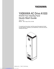
YASKAWA A1000 Series Quick Start Manual (44 pages)
IP23/54 Floor Standing Panel, 400 V Class: 90 to 315 kW
Brand: YASKAWA
|
Category: Controller
|
Size: 4 MB
Table of Contents
-
Table of Contents
3
-
Safety Instructions and General Warnings
4
-
Mechanical Installation
9
-
Electrical Installation
13
-
Keypad Operation
22
-
Start up
24
-
Parameter Table
29
-
Troubleshooting
34
-
Maintenance
38
-
Safe Disable Input Function
40

YASKAWA A1000 Series Manual (19 pages)
Brand: YASKAWA
|
Category: Controller
|
Size: 3 MB
Table of Contents
-
Table of Contents
3
-
Preface and Safety
5
-
Applicable Documentation
5
-
Supplemental Safety Information
5
-
Obtaining Support
5
-
Product Overview
6
-
Applicable Models
6
-
Application Selection
7
-
Traverse Anti-Phase
7
-
Basic Concept
7
-
Limitations
7
-
Control Modes, Symbols, and Terms
8
-
Related Parameters and Functions
9
-
Modified Parameters
9
-
Additional Parameters
9
-
Function Text
10
-
Monitor Function Text
10
-
Multi-Function Input Settings
10
-
Multi-Function Output Settings
10
-
Function Description
11
-
Machine Parameter Selection
11
-
Application Example
12
-
Software and Hardware Configuration for A1000 Traverse
12
-
Implementation
12
-
Sample Operating Parameters
12
-
Master and Slave Output Diagram: Standard Operation
13
-
Traverse Operation Exceeds Maximum Output Frequency
14
-
Changing Reference Frequency
14
-
Traverse Mode Operation with Changing Frequency Reference
15
-
Revision History
16

YASKAWA A1000 Series Installation Manual (31 pages)
Motor PG Feedback Line Driver Interface
Brand: YASKAWA
|
Category: Recording Equipment
|
Size: 3.18 MB
Table of Contents
-
Table of Contents
2
-
Preface and Safety
3
-
Product Overview
6
-
Receiving
7
-
Option Components
8
-
Installation Procedure
9
-
Related Parameters
21
-
Troubleshooting
24
-
Specifications
29
YASKAWA A1000 Series Installation Manual (30 pages)
AC Drive, Option, Analog Input
Brand: YASKAWA
|
Category: DC Drives
|
Size: 3.36 MB
Table of Contents
-
Table of Contents
3
-
Preface and Safety
4
-
Product Overview
7
-
Receiving
8
-
Option Components
9
-
Installation Procedure
10
-
Related Parameters
22
-
Troubleshooting
26
-
Specifications
28

YASKAWA A1000 Series Manual (36 pages)
AC Drive
Brand: YASKAWA
|
Category: DC Drives
|
Size: 1.71 MB
YASKAWA A1000 Series Installation Manual (24 pages)
AC Drive Option, 120 Vac Digital input
Brand: YASKAWA
|
Category: Controller
|
Size: 1.98 MB
Table of Contents
-
Table of Contents
3
-
Preface and Safety
4
-
Product Overview
7
-
Receiving
8
-
Option Components
9
-
Installation Procedure
10
-
Troubleshooting
21
-
Specifications
22
YASKAWA A1000 Series Setup (4 pages)
TCP Modbus Communication
Brand: YASKAWA
|
Category: Media Converter
|
Size: 0.89 MB
Advertisement
Related Products
-
YASKAWA A1000 HHP
-
YASKAWA A14
-
YASKAWA AO-A3
-
YASKAWA APMC-CP2700-E
-
YASKAWA AI-A3
-
YASKAWA ANTAIOS
-
YASKAWA A01
-
YASKAWA AC Drive
-
YASKAWA SGDV AE5A Series
-
YASKAWA ACS-500
YASKAWA Categories
Controller
DC Drives
Servo Drives
Robotics
Control Unit
More YASKAWA Manuals