-
Contents
-
Table of Contents
-
Troubleshooting
-
Bookmarks
Quick Links
®
3Com
Baseline Switch 2916-SFP Plus
and Baseline Switch 2924-SFP Plus
User Guide
3CBLSG16 / 3CBLSG24
www.3Com.com
Part Number 10016143 Rev. AA
Published May 2007
Related Manuals for 3Com 2924-SFP
Summary of Contents for 3Com 2924-SFP
-
Page 1: User Guide
® 3Com Baseline Switch 2916-SFP Plus and Baseline Switch 2924-SFP Plus User Guide 3CBLSG16 / 3CBLSG24 www.3Com.com Part Number 10016143 Rev. AA Published May 2007…
-
Page 2
All other company and product names may be trademarks of the respective companies with which they are associated. ENVIRONMENTAL STATEMENT It is the policy of 3Com Corporation to be environmentally friendly in all operations. To uphold our policy, we are committed to: Establishing environmental performance standards that comply with national legislation and regulations. -
Page 3: About This Guide
This guide provides information about the Web user interface for the 3Com® Baseline Switch 2916-SFP Plus and Baseline Switch 2924-SFP Plus. The Web interface is a network management system that allows you to configure, monitor, and troubleshoot your switch from a remote web browser.
-
Page 4
BOUT UIDE ■ ■ ■ ■ ■ ■ ■ ■ ■ ■ ■ Aggregating Ports — Provides information for configuring Link Aggregation which optimizes port usage by linking a group of ports together to form a single LAG. Configuring VLANs — Provides information for configuring VLANs. VLANs are logical subgroups with a Local Area Network (LAN) which combine user stations and network devices into a single virtual LAN segment, regardless of the physical LAN segment to which they are… -
Page 5: Intended Audience
Most user guides and release notes are available in Adobe Acrobat Reader Portable Document Format (PDF) or HTML on the 3Com Web site: ■ Conventions Table 1 lists conventions that are used throughout this guide.
-
Page 6: Table Of Contents
Default Users and Passwords… 27 Upgrading Software using the CLI… 27 SING THE Starting the 3Com Web Interface… 28 Understanding the 3Com Web Interface … 30 Using Screen and Table Options … 33 Saving the Configuration … 37 Resetting the Device … 38 Restoring Factory Defaults…
-
Page 7
IEWING ASIC ETTINGS Viewing Device Settings …41 Viewing Color Keys …43 ANAGING EVICE Configuring System Access…45 Defining RADIUS Clients…50 Defining Port-Based Authentication (802.1X)…52 Defining Access Control Lists …57 Enabling Broadcast Storm…78 ENERAL YSTEM NFORMATION Viewing System Description…80 Configuring System Name Information …82 Configuring System Time …83 ONFIGURING ORTS… -
Page 8
Modifying VLAN Settings … 105 Modifying Port VLAN Settings … 107 Removing VLANs … 108 ONFIGURING Defining IP Addressing … 109 Configuring ARP Settings… 110 Configuring Address Tables… 114 IGMP S ONFIGURING Introduction… 123 Defining IGMP Snooping… 124 ONFIGURING PANNING Viewing Spanning Tree … -
Page 9
Configuring Port Mirroring …175 Viewing Cable Diagnostics …178 ETWORK 3Com Network Supervisor…181 3Com Network Director …182 3Com Network Access Manager …182 3Com Enterprise Management Suite …183 Integration Kit with HP OpenView Network Node Manager …183 EVICE PECIFICATIONS AND Related Standards …184 Environmental …184… -
Page 10
Console Cable … 189 Null Modem Cable… 190 PC-AT Serial Cable … 190 Modem Cable… 190 Ethernet Port RJ-45 Pin Assignments … 191 ROUBLESHOOTING Problem Management … 192 Troubleshooting Solutions … 192 CLI R EFERENCE Getting Started with the Command Line Interface … 195 CLI Commands … -
Page 11: Getting Started
ETTING This chapter contains introductory information about the 3Com Switch 2916-SFP Plus and the Baseline Switch 2924-SFP Plus and how they can be used in your network. It covers summaries of hardware and software features and also the following topics: About the Switch 2916 and 2924 ■…
-
Page 12: About The Switch 2916 And 2924
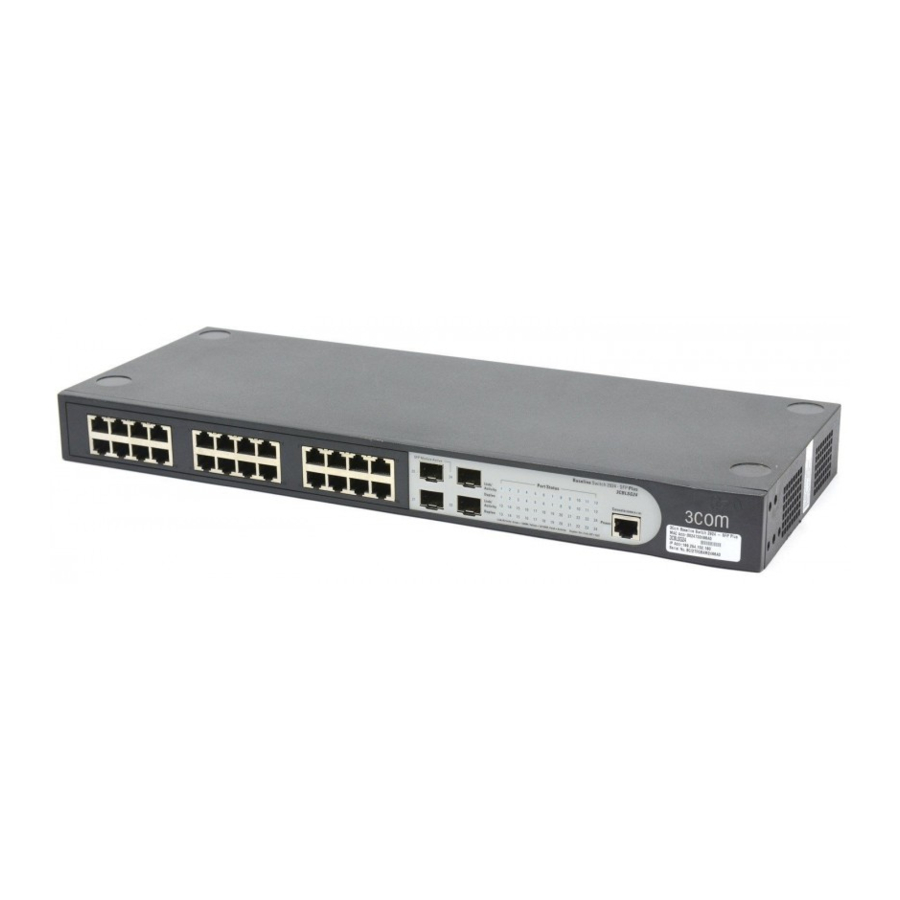
Table 1 summarizes the hardware features supported by the Switch 2916 Hardware Features and 2924. Table 1 Hardware Features Baseline Switch 2916-SFP Plus 16-Port Baseline Switch 2924-SFP Plus 24-Port Full Gigabit speed access ports Jumbo frames Port security Link aggregation control protocol (LACP)
-
Page 13: Front Panel Detail
Figure 1 shows the front panel of the Switch 2916-SFP Plus 16-Port unit. Figure 1 Switch 2916 SFP 16-Port—front panel Figure 2 shows the front panel of the Switch 2924-SFP Plus 24-Port unit. Figure 2 Switch 2924 SFP Plus 24-Port—front panel…
-
Page 14: Led Status Indicators
1: G HAPTER ETTING TARTED LED Status The 2916-SFP Plus 16-Port and 24-Port Ethernet switches provide LED Indicators indicators on the front panel for your convenience to monitor the switch. Table 2 describes the meanings of the LEDs. Table 2 Description on the LEDs of the Switch 2916 and 2924 Label Status Power…
-
Page 15: System Specifications
58 W (full load) Operating temperature 0 to 40 °C (32 to 113 °F) Relative humidity 10 to 90% noncondensing System Specifications Switch 2924-SFP Plus 24-Port 3CBLSG24 24 × 10/100/100 Mbps Ethernet ports Four Gigabit SFP Combo ports 84 W…
-
Page 16: Installing The Switch
AVERTISSEMENT: Consignes de securite. Avant d’installer ou d’enlever tout composant de Switch ou d’entamer une procedure de maintenance, lisez les informations relatives a la securite qui se trouvent dans 3Com Switch Family Safety and Regulatory Information. VORSICHT: Sicherheitsinformationen. Bevor Sie Komponenten aus…
-
Page 17: Setting Up For Management
Console port for basic operations of the switch including setting and viewing the IP address, configuring user accounts, upgrading switch firmware, and more. Refer to “3Com CLI Reference Guide” on page 195. Web Interface Each switch has an internal set of web pages that allow you to manage…
-
Page 18: Switch Setup Overview
You can manage a switch using any network management workstation running the Simple Network Management Protocol (SNMP) as shown in Figure 4. For example, you can use the 3Com Network Director software, available from the 3Com website. Figure 4 SNMP Management over the Network Refer to “Setting Up SNMP Management V1 or V2”…
-
Page 19
Figure 5 Initial Switch Setup and Management Flow Diagram IP Information is automatically configured using DHCP See page 20 How do you want to connect to the Switch? Connect to the Connect to a front panel console port and use port and use the Web the Command Line Interface. -
Page 20: Ip Configuration
1: G HAPTER ETTING TARTED IP Configuration The switch’s IP configuration is determined automatically using DHCP, or manually using values you assign. Automatic IP Configuration using DHCP By default the switch tries to configure its IP Information without requesting user intervention. It tries to obtain an IP address from a DHCP server on the network.
-
Page 21: Using The Command Line Interface (Cli)
IP address, or to view the IP address that was assigned automatically (for Interface (CLI) example, by a DHCP server). For more information about the CLI, refer to “3Com CLI Reference Guide” on page 195. Connecting to the This section describes how to connect to your switch through the Console Port Console port.
-
Page 22
1: G HAPTER ETTING TARTED Connecting the Workstation to the Switch 1 Connect the workstation to the console port using the console cable as shown in Figure 6. Figure 6 Connecting a Workstation to the Switch using the Console Port To connect the cable: a Attach the cable’s RJ-45 connector to the Console port of the switch. -
Page 23
1 Connect to the switch Console port as described in “Connecting to the 2 The command line interface login sequence begins as soon as the switch 3 At the login prompt, enter 4 Press Return. If you have logged on correctly, Select menu option# 5 Enter the IP address and subnet mask for the switch as follows: 6 Enter the logout command to terminate the CLI session. -
Page 24
See “Methods of Managing a Switch” on page 17. For more information about the CLI, refer to “3Com CLI Reference Guide” on page 195. If you do not intend to use the command line interface using the console port to manage the switch, you can logout, disconnect the serial cable and close the terminal emulator software. -
Page 25: Setting Up Web Interface Management
Setting Up Web This section describes how you can set up web interface management Interface over the network. Management Prerequisites ■ ■ ■ Choosing a Browser To display the web interface correctly, use one of the following Web browser and platform combinations: Table 4 Supported Web Browsers and Platforms For the browser to operate the web interface correctly, JavaScript and Cascading Style Sheets must be enabled on your browser.
-
Page 26: Setting Up Snmp Management V1 Or V2
Network Management Protocol (SNMP) to manage the switch. 3Com offers a range of network management applications to address networks of all sizes and complexity. See “3Com Network Management” on page 181. Be sure the management workstation is connected to the switch using a port in VLAN 1 (the Default VLAN).
-
Page 27: Default Users And Passwords
Default Users and If you intend to manage the switch or to change the default passwords, Passwords you must log in with a valid user name and password. The switch has one default user name. The default user is listed in Table 5. Table 5 Default Users Use the admin default user name (no password) to login and carry out initial switch setup.
-
Page 28: Using The 3C Om Web Interface
Users and access levels are described in Configuring System Access Section. Login information is always handled in the local database. A unique password is required of each user. Two access levels exist on the 3Com Web Interface: ■ ■…
-
Page 29
Accessing the 3Com This section contains information on starting the 3Com Web interface. Web Interface To access the 3Com user interface: 1 Open an Internet browser. 2 Enter the device IP address in the address bar and press Enter. The Enter… -
Page 30: Understanding The 3Com Web Interface
2: U HAPTER SING THE Figure 8 3Com Web Interface Home Page Understanding the The 3Com Web Interface Home Page contains the following views: 3Com Web ■ Interface ■ ■ NTERFACE Tab View — Provides the device summary configuration located at the top of the home page.
-
Page 31
Device Representation — Provides an explanation of the user ■ interface buttons, including both management buttons and task icons. Using the Web Interface Management Buttons — Provides ■ instructions for adding, modifying, and deleting configuration parameters. Understanding the 3Com Web Interface… -
Page 32
2: U HAPTER SING THE Device The 3Com Web Interface Home Page contains a graphical panel Representation representation of the device that appears within the Device View Tab. To access the Device Representation: 1 Click Device Summary > Device View. -
Page 33: Using Screen And Table Options
Using Screen and 3Com contains screens and tables for configuring devices. This section Table Options contains the following topics: ■ ■ ■ ■ Viewing Configuration Information To view configuration information: 1 Click Port > Administration > Summary. The Port Settings Summary…
-
Page 34
HAPTER SING THE Adding Configuration Information User-defined information can be added to specific 3Com Web Interface pages, by opening the IP Setup Page. For example, to configure IP Setup: 1 Click Administration > IP Setup. The IP Setup Page opens: Figure 12 IP Setup Page 2 Enter requisite information in the text field. -
Page 35
Modifying Configuration Information 1 Click Administration > System Access > Modify. The System Access Modify Page opens: Figure 13 System Access Modify Page 2 Modify the fields. 3 Click Apply. The access fields are modified. Using Screen and Table Options… -
Page 36
2: U HAPTER SING THE Removing Configuration Information 1 Click Administration > System Access > Remove. The System Access Remove Page opens: Figure 14 System Access Remove Page 2 Select the user account to be deleted. 3 Click Remove. The user account is deleted, and the device is updated. NTERFACE… -
Page 37: Saving The Configuration
Saving the Configuration changes are only saved to the device once the user saves Configuration the changes to the flash memory. The Save Configuration tab allows the latest configuration to be saved to the flash memory. To save the device configuration: 1 Click Save Configuration.
-
Page 38: Resetting The Device
2: U HAPTER SING THE Resetting the The Reset Page enables resetting the device from a remote location. Device To prevent the current configuration from being lost, use the Save Configuration Page to save all user-defined changes to the flash memory before resetting the device.
-
Page 39: Restoring Factory Defaults
Restoring Factory The Restore option appears on the Reset Page. The Restore option Defaults restores device factory defaults. To restore the device: 1 Click Administration > Reset. The Reset Page opens: Figure 18 Reset Page The Reset Page contains the following fields: 2 Click the Initialize button.
-
Page 40: Logging Off The Device
2: U HAPTER SING THE Logging Off the To log off the device: Device 1 Click Logout. The Logout Page opens. 2 The following message appears: 3 Click OK. The 3Com Web Interface Home Page closes. NTERFACE…
-
Page 41: Viewing
This section contains information about viewing basic settings available from the Web interface home page, including the Device Summary page and the Color Keys page. Viewing Device The Device Summary Page displays general information, including the Settings system name, location, and contact, the system MAC address, System Object ID, System Up Time, and software, boot, and hardware versions.
-
Page 42
0-160 characters. Serial Number — Displays the device serial number. Product 3C Number — Displays the 3Com device 3C number. System Object ID — Displays the vendor’s authoritative identification of the network management subsystem contained in the entity. -
Page 43: Viewing Color Keys
Viewing Color Keys The Color Key Page provides information about the RJ45 or SFP port status. To view color keys: 1 Click Device Summary > Color Key. The Color Key Page opens: Figure 20 Color Key Page The Color Key Page contains the following fields: ■…
-
Page 44: Managing Device Security
The Management Security section provides information for configuring system access, defining RADIUS authentication, port-based authentication and defining access control lists. This section includes the following topics: Configuring System Access ■ Defining RADIUS Clients ■ Defining Port-Based Authentication (802.1X) ■ Defining Access Control Lists ■…
-
Page 45: Configuring System Access
Access levels provide read or read/write permissions to users for configuring the switch. Login information is managed in the local database. A unique password is required of each user. Two access levels exist on the 3Com Web Interface: ■ ■…
-
Page 46
4: M HAPTER ANAGING EVICE Viewing System The System Access Summary Page displays the current users and access Access Settings levels defined on the device. To view System Access settings: 1 Click Administration > System Access > Summary. The System Access Summary Page opens: Figure 21 System Access Summary Page The System Access Summary Page contains the following fields:… -
Page 47
Defining System The System Access Setup Page allows network administrators to define Access users, passwords, and access levels for users using the System Access Interface. Monitor users have no access to this page. 1 Click Administration > System Access > Setup. The System Access Setup Page opens: Figure 22 System Access Setup Page The System Access Setup Page contains the following fields:… -
Page 48
4: M HAPTER ANAGING EVICE Modifying System The System Access Modify Page allows network administrators to modify Access users, passwords, and access levels using the System Access Interface. Monitor users have no access to this page. 1 Click Administration > System Access > Modify. The System Access Modify Page opens: Figure 23 System Access Modify Page The System Access Modify Page contains the following fields:… -
Page 49
Removing System The System Access Remove Page allows network administrators to Access remove users from the System Access Interface. Monitor users have no access to this page. To remove users: 1 Click Administration > System Access > Remove. The System Access Remove Page opens: Figure 24 System Access Remove Page The System Access Remove Page contains the following fields:… -
Page 50: Defining Radius Clients
4: M HAPTER ANAGING Defining RADIUS Remote Authorization Dial-In User Service (RADIUS) servers provide Clients additional security for networks. RADIUS servers provide a centralized authentication method for 802.1X. The default parameters are user-defined, and are applied to newly defined RADIUS servers. If new default parameters are not defined, the system default values are applied to newly defined RADIUS servers.
-
Page 51
Authentication Port — Identifies the authentication port. The ■ authentication port is used to verify the RADIUS server authentication. The authenticated port default is 1812. Number of Retries — Defines the number of transmitted requests ■ sent to the RADIUS server before a failure occurs. Possible field values are 1-10. -
Page 52: Defining Port-Based Authentication (802.1X)
4: M HAPTER ANAGING Defining Port-Based Port-based authentication authenticates users on a per-port basis via an Authentication external server. Only authenticated and approved system users can (802.1X) transmit and receive data. Ports are authenticated via the RADIUS server using the Extensible Authentication Protocol (EAP). Port-based authentication includes: ■…
-
Page 53
Viewing 802.1X The 802.1X Summary Page allows the network administrator to view Authentication port-based authentication settings. To view Port-based Authentication: 1 Click Security > 802.1X > Summary. The 802.1X Summary Page opens: Figure 26 802.1X Summary Page The 802.1X Summary Page contains the following fields: Port —… -
Page 54
4: M HAPTER ANAGING EVICE ■ ■ ■ ■ ■ 2 Click Apply. Port Authentication is enabled, and the device is updated. Defining 802.1X The 802.1X Setup Page contains information for configuring 802.1X Authentication global settings on the device and defining specific 802.1X setting for each port individually. -
Page 55
To configure 802.1X Settings: 1 Click Security > 802.1X > Setup. The 802.1X Setup Page opens: Figure 27 802.1X Setup Page 802.1X Setup Page contains the following fields: 802.1X Global Settings Port Based Authentication State — Indicates if Port Authentication ■… -
Page 56
4: M HAPTER ANAGING EVICE ■ 802.1X Port Settings ■ ■ ■ ■ 2 Define the fields. 3 Click Apply. The ECURITY access. For example, a network administrator can use Guest VLANs to deny network access via port-based authentication, but grant Internet access to unauthorized users. -
Page 57: Defining Access Control Lists
Defining Access Access Control Lists (ACL) allow network managers to define Control Lists classification actions and rules for specific ingress ports. Packets entering an ingress port, with an active ACL are either admitted or denied entry. If they are denied entry, the port can be disabled. For example, an ACL rule is defined states that port number 20 can receive TCP packets, however, if a UDP packet is received, the packet is dropped.
-
Page 58
4: M HAPTER ANAGING EVICE Viewing MAC Based The MAC Based ACL Summary Page displays information regarding MAC ACLs Based ACLs configured on the device. Ports are reactivated from the Interface Configuration Page. To view MAC Based ACLs: 1 Click Device > ACL > MAC Based ACL > Summary. The MAC Based ACL Summary Page opens: Figure 28 The MAC Based ACL Summary Page contains the following fields:… -
Page 59
Ethertype — Provides an identifier that differentiates between ■ various types of protocols. Action — Indicates the ACL forwarding action. In addition, the port ■ can be shut down, a trap can be sent to the network administrator, or packet is assigned rate limiting restrictions for forwarding. The options are as follows: ■… -
Page 60
4: M HAPTER ANAGING EVICE Add Rules to ACL ■ ■ ■ ■ ■ ■ ■ ■ ■ ■ ECURITY Priority — Indicates the ACE priority, which determines which ACE is matched to a packet on a first-match basis. The possible field values are 1-2147483647. -
Page 61
packet is assigned rate limiting restrictions for forwarding. The options are as follows: Permit — Forwards packets which meet the ACL criteria. ■ Deny — Drops packets which meet the ACL criteria. ■ Shutdown — Drops packet that meets the ACL criteria, and ■… -
Page 62
4: M HAPTER ANAGING EVICE Modify ■ ■ ■ ■ ■ ■ ■ ■ ■ ■ ECURITY Priority — Indicates the rule priority, which determines which rule is matched to a packet on a firstmatch basis. Source MAC Address — Matches the source MAC address to which packets are addressed to the ACE. -
Page 63
2 Define the fields. 3 Click Apply. The MAC based settings are modified, and the device is Removing MAC Based ACLs 1 Click Device > ACL > MAC Based ACL > Remove. The MAC Based ACL Permit — Forwards packets which meet the ACL criteria. ■… -
Page 64
4: M HAPTER ANAGING EVICE ■ ■ ■ ■ ■ ■ ■ ■ 2 Select the ACL Name to be deleted. 3 Select the ACL to be removed from the table. 4 Click the Remove checkbox. 5 Click Apply. The selected ACLs are deleted, and the device is updated. ECURITY Priority —… -
Page 65
Viewing IP Based The IP Based ACL Summary Page displays information regarding IP Based ACLs ACLs configured on the device. To view IP Based ACLs: 1 Click Device > ACL > IP Based ACL > Summary. The IP Based ACL Summary Page opens: Figure 32 IP Based ACL Summary Page The IP Based ACL Summary Page contains the following fields:… -
Page 66
4: M HAPTER ANAGING EVICE ■ ■ ■ ■ ■ ■ ■ ■ ■ Defining IP Based Access Control Lists (ACL) allow network managers to define ACLs classification actions and rules for specific ingress ports. Your switch supports up to 256 ACLs. Packets entering an ingress port, with an active ACL, are either admitted or denied entry. -
Page 67
To configure IP Based Access Control Lists: 1 Click Device > ACL > IP Based ACL > Setup. The IP Based ACL Setup Page opens: Figure 33 IP Based ACL Setup Page The IP Based ACL Setup Page contains the following fields: Selection ACL —… -
Page 68
4: M HAPTER ANAGING EVICE ■ ■ ■ ■ ■ ECURITY Destination Port — Indicates the destination port that is used for matched packets. Enabled only when TCP or UDP are selected in the Protocol list. The field value is either user defined or Any. If Any is selected, the IP based ACL is applied to any destination port. -
Page 69
IGMP Type — Specifies an IGMP message type. ■ Any — Does not filter for an IGMP message type. ■ Source IP Address — If selected, enables matching the source port IP ■ address to which packets are addressed to the ACE, according to a wildcard mask. -
Page 70
4: M HAPTER ANAGING EVICE ■ ■ 2 Select an ACL from the ACL Name drop-down list. 3 Define the rule setup fields. 4 Click Apply. The ACL rule setup is enabled, and the device is updated. Modifying IP Based The IP Based ACL Modify Page allows the network administrator to ACLs modify IP Based ACLs settings. -
Page 71
The IP Based ACL Modify Page contains the following fields: Selection ACL — Selects the ACL to be modified. ■ Modify Rule Priority — Defines the ACL priority. ACLs are checked on the first fit ■ basis. The ACL priority defines the ACL order in the ACL list. Protocol —… -
Page 72
4: M HAPTER ANAGING EVICE ■ ■ ■ ■ ■ ECURITY For each TCP flag, the possible field values are: Set — Enables the TCP flag. ■ Unset — Disables the TCP flag. ■ Don’t Care — Does not check the packet’s TCP flag. ■… -
Page 73
Match DSCP — Matches the packet DSCP value to the ACL. Either ■ the DSCP value or the IP Precedence value is used to match packets to ACLs. Match IP Precedence — Matches the packet IP Precedence value to ■ the ACE. -
Page 74
4: M HAPTER ANAGING EVICE The IP Based ACL Remove Page contains the following fields: ■ ■ ■ ■ ■ ■ ■ ■ ■ ■ ■ ■ ■ ■ ■ ■ ■ ECURITY ACL Name — Contains a list of the IP-based ACLs. Remove ACL —… -
Page 75
2 Select an ACL to be removed. 3 Click Apply. The selected ACLs are deleted, and the device is updated. Viewing ACL Binding The ACL Binding Summary Page displays the user-defined ACLs mapped to the interfaces. To view ACL Binding: 1 Click Device >… -
Page 76
4: M HAPTER ANAGING EVICE Configuring ACL The ACL Binding Setup Page allows the network administrator to bind Binding specific ports to MAC or IP Based ACLs. The monitor user has no access to this page. To define ACL Binding: 1 Click Device >… -
Page 77
Removing ACL The ACL Binding Remove Page allows the network administrator to Binding remove user-defined ACLs from a selected interface. Monitor users have no access to this page. To remove ACL Binding: 1 Click Device > ACL > ACL Binding > Remove. The ACL Binding Remove Page opens: Figure 38 ACL Binding Remove Page The ACL Binding Remove Page contains the following fields:… -
Page 78: Enabling Broadcast Storm
4: M HAPTER ANAGING Enabling Broadcast Broadcast Storm limits the amount of Multicast and Broadcast frames Storm accepted and forwarded by the device. When Layer 2 frames are forwarded, Broadcast and Multicast frames are flooded to all ports on the relevant VLAN.
-
Page 79
The Broadcast Storm Setup Page contains the following fields: Broadcast Storm Control — Indicates if forwarding Broadcast ■ packet types is enabled on the interface. Disabled — Disables broadcast control on the selected port. ■ Broadcast — Enables broadcast control on the selected port. ■… -
Page 80: General System Information
This section contains information about configuring general system parameters, and includes the following: ■ ■ ■ Viewing System The Device View Page displays parameters for configuring general device Description information, including the system name, MAC Address, software and hardware versions, and more. 1 Click Device Summary.
-
Page 81
■ “Configuring System Name Information” page 82. Serial Number — Displays the device serial number. Not editable. ■ Product 3C Number — Displays the 3Com device model number. ■ Not editable. System Object ID — Displays the vendor’s authoritative identification ■… -
Page 82: Configuring System Name Information
5: G HAPTER ENERAL YSTEM Configuring System The System Name Page allows the Network Administrator to provide a Name Information user-defined system name, location, and contact information for the device. Monitor users have read-only permissions on this page. To configure the System Name: 1 Click Administration >…
-
Page 83: Configuring System Time
Configuring System The System Time Setup Page contains fields for defining system time Time parameters for the local hardware clock. Daylight Savings Time can be enabled on the device. Monitor users have limited permissions on this page. Country specific times need to be added manually. To configure the System Time: 1 Click Administration >…
-
Page 84
5: G HAPTER ENERAL YSTEM ■ ■ ■ ■ ■ ■ ■ 2 Define the local Time and Date. 3 Enable or disable automatic DST by clicking the Daylight Savings box. 4 Configure the region, Time Set Offset, Recurring, From and To fields as appropriate for your location. -
Page 85: Configuring Ports
This section contains information for configuring Port Settings, and includes the following sections: ■ ■ ■ Viewing Port The Port Administration Summary Page permits the network manager to Settings view the current port and LAG setting configuration. The Port Administration Summary Page also displays to which LAGs the port belongs.
-
Page 86
6: C HAPTER ONFIGURING To view Port Settings: 1 Click Port > Administration > Summary. The Port Administration Summary Page opens: Figure 43 Port Administration Summary Page The Port Administration Summary Page contains the following fields: ■ ■ ■ ORTS Port —… -
Page 87
10M — Indicates the port is currently operating at 10 Mbps. ■ 100M — Indicates the port is currently operating at 100 Mbps. ■ 1000M — Indicates the port is currently operating at 1000 Mbps. ■ Duplex Mode — Displays the port duplex mode. This field is ■… -
Page 88: Defining Port Settings
6: C HAPTER ONFIGURING Defining Port The Port Administration Setup Page allows network managers to Settings configure port parameters for specific ports. Monitor users have no access to this page. To configure Port Settings: 1 Click Port > Administration > Setup. The Port Administration Setup Page opens: Figure 44 Port Administration Setup Page The Port Administration Setup Page contains the following fields:…
-
Page 89
10 — Indicates the port is currently operating at 10 Mbps. ■ 100 — Indicates the port is currently operating at 100 Mbps. ■ 1000 — Indicates the port is currently operating at 1000 Mbps. ■ Auto — Use to automatically configure the port. ■… -
Page 90: Viewing Port Details
6: C HAPTER ONFIGURING Viewing Port The Port Detail Page displays current port parameters for specific ports. Details Monitor users have no access to this page. To view Port Details: 1 Click Port > Administration > Detail. The Port Detail Page opens: Figure 45 Port Detail Page The Port Detail Page contains the following fields: ■…
-
Page 91
Speed — Displays the configured rate for the port. The port type ■ determines what speed setting options are available. Port speeds can only be configured when auto negotiation is disabled. The possible field values are: 10 — Indicates the port is currently operating at 10 Mbps. ■… -
Page 92: Aggregating Ports
GGREGATING This section contains information for configuring Link Aggregation, which optimizes port usage by linking a group of ports together to form a single LAG. A Link Aggregated Group (LAG) aggregates ports or VLANs into a single virtual port or VLAN bandwidth between the devices, increases port flexibility, and provides link redundancy.
-
Page 93: Viewing Link Aggregation
Viewing Link The Link Aggregation Summary Page displays port usage by linking a Aggregation group of ports together to form a single LAG. Aggregating ports multiplies the bandwidth between the devices, increases port flexibility, and provides link redundancy. To view Link Aggregation: 1 Click Ports >…
-
Page 94
7: A HAPTER GGREGATING 1 Click Ports > Link Aggregation > Create. The Link Aggregation Create Page opens: Figure 47 Link Aggregation Create Page The Link Aggregation Create Page includes the following fields: ■ ■ ■ ■ Summary ■ ■ 2 Define the fields. -
Page 95: Modifying Link Aggregation
Modifying Link The Link Aggregation Modify Page optimizes port usage by linking a Aggregation group of ports together to form a single LAG. Aggregating ports multiplies the bandwidth between the devices, increases port flexibility, and provides link redundancy. Monitor users have no access to this page. To modify Link Aggregation: 1 Click Ports >…
-
Page 96: Removing Link Aggregation
7: A HAPTER GGREGATING Summary ■ ■ ■ 2 Define the fields. 3 Click Apply. Link Aggregation is configured, and the application is updated. Removing Link The Link Aggregation Remove Page allows the network manager to Aggregation remove group IDs containing member ports. Monitor users have no access to this page.
-
Page 97: Viewing Lacp
The Link Aggregation Remove Page includes the following fields: ■ 2 Select a group ID to be removed 3 Click Remove. The Link aggregation is removed, and the device is updated. Viewing LACP LAG ports can contain different media types if the ports are operating at the same speed.
-
Page 98: Modifying Lacp
7: A HAPTER GGREGATING The LACP Summary Page contains the following fields: ■ ■ ■ Modifying LACP LAG ports can contain different media types if the ports are operating at the same speed. Aggregated links can be set up manually or automatically established by enabling LACP on the relevant links.
-
Page 99
The LACP Modify Page contains the following fields: LACP System Priority — Specifies system priority value. The field ■ range is 1-65535. The field default is 1 Select Port — Displays the port number to which timeout and priority ■ values are assigned. -
Page 100: Configuring Vlans
ONFIGURING This section contains the following topics: VLAN Overview ■ Viewing VLAN Details ■ Viewing VLAN Port Details ■ Creating VLANs ■ Modifying VLAN Settings ■ Modifying Port VLAN Settings ■ Removing VLANs ■ VLAN Overview VLANs are logical subgroups with a Local Area Network (LAN) which combine user stations and network devices into a single unit, regardless of the physical LAN segment to which they are attached.
-
Page 101
VLAN tagging provides a method of transferring VLAN information between VLAN groups. VLAN1is the default VLAN. All ports are untagged members of VLAN1 by default. If any port becomes an untagged member of a different VLAN, then the port is removed from untagged membership of VLAN1. -
Page 102: Viewing Vlan Details
8: C HAPTER ONFIGURING Viewing VLAN The VLAN Detail Page provides information and global parameters on Details VLANS configured on the system. 1 Click Device > VLAN > VLAN Detail. The VLAN Detail Page opens: Figure 52 VLAN Detail Page The VLAN Detail Page contains the following information: ■…
-
Page 103: Viewing Vlan Port Details
Viewing VLAN Port The VLAN Port Detail Page provides displays VLAN configured ports. Details To view VLAN Port details: 1 Click Device > VLAN > Port Detail. The VLAN Port Detail Page opens: Figure 53 VLAN Port Detail Page The VLAN Port Detail Page contains the following information: ■…
-
Page 104: Creating Vlans
8: C HAPTER ONFIGURING Creating VLANs The VLAN Setup Page allows the network administrator to create user-defined VLANs. The monitor users have no access to this page. To create VLANs: 1 Click Device > VLAN > Setup. The VLAN Setup Page opens: Figure 54 VLAN Setup Page The VLAN Setup Page contains the following fields: Create…
-
Page 105: Modifying Vlan Settings
3 Click Create. The VLANs are configured, and the device is updated. To rename a VLAN: 1 Highlight a VLAN to be renamed from the VLAN list. 2 Enter the new name for the VLAN. 3 Click Rename. The VLAN is renamed, and the device is updated. Modifying VLAN The Modify VLAN Page allows the network manager to rename VLANs Settings…
-
Page 106
8: C VLAN HAPTER ONFIGURING ■ ■ ■ ■ To rename VLANs: 1 Select a VLAN from the list to be renamed. 2 Click Rename. The VLANs are renamed, and the device is updated. To add ports to a VLAN 1 Select a VLAN to modify. -
Page 107: Modifying Port Vlan Settings
Modifying Port The Modify VLAN Port Page allows the network manager to modify port VLAN Settings VLAN settings. The monitor users have no access to this page. 1 Click Device > VLAN > Modify Port. The Modify VLAN Port Page opens: Figure 56 Modify VLAN Port Page The Modify VLAN Port Page contains the following fields: ■…
-
Page 108: Removing Vlans
8: C HAPTER ONFIGURING 3 Select Membership type. 4 Enter VLAN ID to be assigned to the port. 5 Click Apply. The VLANs are configured, and the device is updated. Removing VLANs The VLAN Remove Page allows the network administrator to remove VLANs.
-
Page 109: Configuring Ip And Mac Address Information
This section contains information for defining IP interfaces, and includes the following sections: ■ ■ ■ Defining IP The IP Setup Page contains fields for assigning an IP address. The default Addressing gateway is erased when the Default IP address is modified. Packets are forwarded to the default gateway when sent to a remote network.
-
Page 110: Configuring Arp Settings
9: C HAPTER ONFIGURING The IP Setup Page contains the following fields: ■ ■ ■ ■ 2 Select Manual or DHCP mode. 3 If Manual has been selected, configure the IP Address, Subnet Mask and Default Gateway. 4 Click Apply. The IP configuration is enabled, and the device is updated. Configuring ARP The Address Resolution Protocol (ARP) converts IP addresses into physical Settings…
-
Page 111
Viewing ARP Settings The ARP Settings Summary Page displays the current ARP settings. To view ARP Settings: 1 Click Administration > ARP Settings > Summary. The ARP Settings Summary Page opens: Figure 59 ARP Settings Summary Page The ARP Settings Summary Page contains the following fields: ■… -
Page 112: Defining Arp Settings
9: C HAPTER ONFIGURING Defining ARP Settings The ARP Settings Setup Page allows network managers to define ARP parameters for specific interfaces. The monitor users have no access to this page. To configure ARP entries: 1 Click Administration > ARP Settings > Setup. The ARP Settings Setup Page opens: Figure 60 ARP Settings Setup Page The ARP Settings Setup Page contains the following fields:…
-
Page 113
Removing ARP The ARP Settings Remove Page provides parameters for removing ARP Entries entries from the ARP Table. The monitor user has no access to this page. To remove ARP entries: 1 Click Administration > IP Addressing > ARP Settings > Remove. The ARP Settings Remove Page opens: Figure 61 ARP Settings Remove Page The ARP Settings Remove Page contains the following fields:… -
Page 114: Configuring Address Tables
9: C HAPTER ONFIGURING ■ ■ ■ ■ 2 Select the Interface to be removed. 3 Click Remove. The ARP interface is removed, and the device is updated. Configuring MAC addresses are stored in either the Static Address or the Dynamic Address Tables Address databases.
-
Page 115
Viewing Address The Address Table Summary Page displays the current MAC address table Table Settings configuration. To view Address Table settings: 1 Click Monitoring > Address Tables > Summary. The Address Table Summary Page opens: Figure 62 The Address Table Summary Page contains the following fields: State —… -
Page 116
9: C HAPTER ONFIGURING ■ ■ Viewing Port The Port Summary Page allows the user to view the MAC addresses Summary Settings assigned to specific ports. 1 Click Monitoring > Address Tables > Port Summary. The Port Summary Page opens: Figure 63 The Port Summary Page contains the following fields: ■… -
Page 117
■ ■ ■ ■ ■ Adding Entries into The Address Table Add Page allows the network manager to assign MAC Address Tables addresses to ports with VLANs. The monitor users have no access to this page. To add Address Tables: 1 Click Monitoring >… -
Page 118
9: C HAPTER ONFIGURING The Address Table Add Page contains the following fields: ■ ■ ■ ■ ■ ■ ■ ■ ■ 2 Define the fields. 3 Click Apply. The MAC address is added to the address table, and the device is updated. -
Page 119
Defining Aging Time The Address Table Setup Page allows the network manager to define the Address Table Aging Time. The Aging Time is the amount of time the MAC Addresses remain in the Dynamic MAC Address Table before they are timed out if no traffic from the source is detected. The default value is 300 seconds. -
Page 120
9: C HAPTER ONFIGURING Removing Address The Port Remove Page allows the network manager to remove ports from Table Ports the address tables. The monitor users have no access to this page. To remove ports: 1 Click Monitoring > Address Tables > Port Remove. The Port Remove Page opens: Figure 66 Port Remove Page The Port Remove Page contains the following fields:… -
Page 121
Aging Time — Specifies the amount of time the MAC Address ■ remains in the Dynamic MAC Address before it is timed out if no traffic from the source is detected. The default value is 300 seconds. 2 Select the port(s) to remove. 3 Click Remove. -
Page 122
9: C HAPTER ONFIGURING ■ ■ 2 Select the MAC addresses to remove. 3 Click Remove. The selected MAC addresses are removed from the MAC address table, and the device is updated. MAC A DDRESS NFORMATION Config Static — Indicates the MAC address is statically configured. ■… -
Page 123: Configuring Igmp Snooping
Introduction This section contains information for configuring IGMP Snooping. When IGMP Snooping is enabled globally, all IGMP packets are forwarded to the CPU. The CPU analyzes the incoming packets and determines: ■ ■ ■ Ports requesting to join a specific Multicast group issue an IGMP report, specifying that Multicast group is accepting members.
-
Page 124: Defining Igmp Snooping
10: C HAPTER ONFIGURING Defining IGMP The IGMP Snooping Setup Page allows network managers to define Snooping IGMP Snooping parameters. The monitor users have read-only access to this page. 1 Click Device > IGMP Snooping > Setup. The IGMP Snooping Setup Page opens: Figure 68 IGMP Snooping Setup Page The IGMP Snooping Setup Page contains the following fields:…
-
Page 125
Defining IGMP Snooping 2 Select Enable IGMP Snooping. 3 Define the fields. 4 Click Apply. IGMP Snooping is enabled, and the device is updated. -
Page 126: Configuring Spanning Tree
This section contains information for configuring STP. The Spanning Tree Protocol (STP) provides tree topography for any arrangement of bridges. STP also provides a single path between end stations on a network, eliminating loops. Loops occur when alternate routes exist between hosts. Loops in an extended network can cause bridges to forward traffic indefinitely, resulting in increased traffic and reducing network efficiency.
-
Page 127: Viewing Spanning Tree
Viewing Spanning The Spanning Tree Summary Page displays the current Spanning Tree Tree parameters for all ports. To view Spanning Tree Summary: 1 Click Device > Spanning Tree > Summary. The Spanning Tree Summary Page opens: Figure 69 Spanning Tree Summary Page The Spanning Tree Summary Page contains the following fields: ■…
-
Page 128
11: C HAPTER ONFIGURING ■ ■ ■ ■ PANNING Root Guard — Restricts the interface from acting as the root port of the switch. The possible field values are: Enable — Indicates Root Guard is enabled on the port ■ Disable —… -
Page 129
Path Cost — Indicates the port contribution to the root path cost. The ■ path cost is adjusted to a higher or lower value, and is used to forward traffic when a path is re-routed. Priority — Priority value of the port. The priority value influences the ■… -
Page 130: Defining Spanning Tree
11: C HAPTER ONFIGURING Defining Spanning Network administrators can assign STP settings to specific interfaces Tree using the Spanning Tree Setup Page. The monitor user has no access to this page. To configure Spanning Tree Setup: 1 Click Device > Spanning Tree > Setup. The Spanning Tree Setup Page opens: Figure 70 Spanning Tree Setup Page The Spanning Tree Setup Page contains the following fields:…
-
Page 131
Global Setting Spanning Tree State — Indicates whether STP is enabled on the ■ device. The possible field values are: Classic — Enables STP on the device. ■ RSTP — Enables RSTP on the device. ■ Disable — Disables STP and RSTP on the device. ■… -
Page 132
11: C HAPTER ONFIGURING Designated Root ■ ■ ■ ■ ■ ■ 2 Define the fields. 3 Click Apply. STP is enabled, and the device is updated. PANNING Bridge ID — Identifies the Bridge priority and MAC address. Root Bridge ID — Identifies the Root Bridge priority and MAC address. -
Page 133: Modifying Spanning Tree
Modifying TheSpanning Tree Modify Page contains information for modifying Spanning Tree Spanning Tree parameters. Monitor users have no access to this page. To modify Spanning Tree: 1 Click Device > Spanning Tree > Modify. The Spanning Tree Modify Page opens: Figure 71 Spanning Tree Modify Page The Spanning Tree Modify Page contains the following fields: ■…
-
Page 134
11: C HAPTER ONFIGURING ■ ■ ■ ■ ■ ■ 2 Select the ports to be defined 3 Define the fields. 4 Click Apply. Spanning Tree is modified on the port, and the device is updated. PANNING Enabled — Indicates fast link is enabled on the port. ■… -
Page 135: Configuring Snmp
Simple Network Management Protocol (SNMP) provides a method for managing network devices. The device supports the following SNMP versions: ■ ■ SNMP v1 and v2c The SNMP agents maintain a list of variables, which are used to manage the device. The variables are defined in the Management Information Base (MIB).
-
Page 136: Defining Snmp Communities
12: C HAPTER ONFIGURING Defining SNMP Access rights are managed by defining communities in the SNMP Communities Communities Setup Page. When the community names are changed, access rights are also changed. SNMP communities are defined only for SNMP v1 and SNMP v2c. Monitor users have no access to this page.
-
Page 137
SNMP Management Management Station — Displays the management station IP ■ address for which the SNMP community is defined. Open Access (0.0.0.0) — Provides SNMP access to all the stations. ■ Community String Standard — Displays pre-defined community strings. The possible ■… -
Page 138: Removing Snmp Communities
12: C HAPTER ONFIGURING Removing SNMP The SNMP Communities Remove Page allows the system manager to Communities remove SNMP Communities. Monitor users have no access to this page. To remove SNMP communities: 1 Click Administration > SNMP > Communities > Remove. The SNMP Communities Remove Page opens: Figure 73 SNMP Communities Remove Page The SNMP Communities Remove Page contains the following fields:…
-
Page 139: Defining Snmp Traps
■ 2 Select the SNMP Community to be removed. 3 Click Remove. The SNMP Community is removed, and the device is updated. Defining SNMP The SNMP Traps Setup Page contains information for defining filters that Traps determine whether traps are sent to specific users, and the trap type sent. Monitor users have no access to this page.
-
Page 140: Removing Snmp Traps
12: C HAPTER ONFIGURING The SNMP Traps Setup Page contains the following fields: ■ ■ ■ 2 Define the relevant fields. 3 Click Apply. The SNMP Traps are defined, and the device is updated. Removing SNMP The SNMP Traps Remove Page allows the network manager to remove Traps SNMP Traps.
-
Page 141
The SNMP Traps Remove Page contains the following fields: Remove — Deletes the currently selected recipient. The possible field ■ values are: Checked — Removes the selected recipient from the list of ■ recipients. Unchecked — Maintains the list of recipients. ■… -
Page 142: Configuring Quality Of Service
Quality of Service (QoS) provides the ability to implement QoS and priority queuing within a network. For example, certain types of traffic that require minimal delay, such as Voice, Video, and real-time traffic can be assigned a high priority queue, while other traffic can be assigned a lower priority queue.
-
Page 143: Viewing Cos Settings
Viewing CoS The CoS Summary Page displays CoS default settings assigned to ports. Settings To view CoS Settings: 1 Click Device > QoS > CoS > Summary. The CoS Summary Page opens: Figure 76 CoS Summary Page The CoS Summary Page contains the following fields: ■…
-
Page 144: Defining Cos
13: C HAPTER ONFIGURING Defining CoS The CoS Setup Page contains information for enabling QoS globally. Monitor users have no access to this page. To configure CoS Settings: 1 Click Device > QoS > CoS Setup. The CoS Setup Page opens: Figure 77 CoS Setup Page The CoS Setup Page contains the following fields: ■…
-
Page 145: Viewing Cos To Queue
Viewing CoS to The CoS to Queue Summary Page contains a table that displays the CoS Queue values mapped to traffic queues. To view CoS Values to Queues: 1 Click Device > QoS > CoS to Queue > Summary. The CoS to Queue Summary Page opens: Figure 78 CoS to Queue Summary Page The CoS to Queue Summary Page contains the following fields:…
-
Page 146
13: C HAPTER ONFIGURING To configure CoS values to queues: 1 Click Policy > QoS General > CoS to Queue > Setup. The CoS to Queue Setup Page opens: Figure 79 CoS to Queue Setup Page The CoS to Queue Setup Page contains the following fields: ■… -
Page 147: Viewing Dscp To Queue
Viewing DSCP to The DSCP to Queue Summary Page contains fields for mapping DSCP Queue settings to traffic queues. For example, a packet with a DSCP tag value of 3 can be assigned to queue 4. To view the DSCP Queue: 1 Click Device >…
-
Page 148: Configuring Dscp Queue
13: C HAPTER ONFIGURING Configuring DSCP The DSCP to Queue Setup Page contains fields for mapping DSCP settings Queue to traffic queues. For example, a packet with a DSCP tag value of 3 can be assigned to queue 1. The monitor user has no access to this page. To map CoS to Queues: 1 Click Device >…
-
Page 149: Configuring Trust Settings
Configuring Trust The Trust Setup Page contains information for enabling trust on Settings configured interfaces. The original device QoS default settings can be reassigned to the interface in the Trust Setup Page. To enable Trust: 1 Click Device > QoS > Trust Setup. The Trust Setup Page opens: Figure 82 Trust Setup Page The Trust Setup Page contains the following fields: ■…
-
Page 150: Viewing Bandwidth Settings
13: C HAPTER ONFIGURING Viewing Bandwidth The Bandwidth Summary Page displays bandwidth settings for a specified Settings interface. To view Bandwidth Settings: 1 Click Device > QoS > Bandwidth > Summary. The Bandwidth Summary Page opens: Figure 83 The Bandwidth Summary Page contains the following fields: ■…
-
Page 151: Defining Bandwidth Settings
Egress Shaping Rates ■ ■ ■ Defining The Bandwidth Setup Page allows network managers to define the Bandwidth Settings bandwidth settings for a specified interface. Interface shaping can be based on an interface and is determined by the lower specified value. The interface shaping type is selected in the Bandwidth Setup Page.
-
Page 152
13: C HAPTER ONFIGURING The Bandwidth Setup Page contains the following fields: Ingress Rate Limit ■ ■ Egress Shaping Rate ■ ■ ■ ■ 2 Select the ports to be configured. 3 Define the fields. 4 Click Apply. The bandwidth is defined, and the device is updated. UALITY OF ERVICE Enable Ingress Rate Limit —… -
Page 153: Defining Voice Vlan
Defining Voice Voice VLAN allows network administrators enhance VoIP service by VLAN configuring ports to carry IP voice traffic from IP phones on a specific VLAN. VoIP traffic has a preconfigured OUI prefix in the source MAC address. Network Administrators can configure VLANs on which voice IP traffic is forwarded.
-
Page 154
13: C HAPTER ONFIGURING Viewing Voice VLANs The Voice VLAN Summary Page contains information about the Voice VLAN currently enabled on the device, including the ports enabled and included in the Voice VLAN. To view Voice VLAN Settings: 1 Click Device > QoS > VoIP > Traffic Setting > Summary. The Voice VLAN Summary Page opens: Figure 85 Voice VLAN Summary Page The Voice VLAN Summary Page contains the following fields:… -
Page 155
■ Defining Voice VLAN The Voice VLAN Setup Page provides information for enabling and defining Voice VLAN globally on the device. To configure Voice VLAN Settings: 1 Click Device > QoS > VoIP > Traffic Setting > Setup. The Voice VLAN Setup Page opens: Figure 86 Voice VLAN Setup Page The Voice VLAN Setup Page contains the following fields:… -
Page 156
13: C HAPTER ONFIGURING ■ 2 Select Enable in the Voice VLAN State field. 3 Define the Voice VLAN and Voice VLAN Aging Time fields. 4 Click Apply. The Voice VLAN is defined, and the device is updated. Defining Voice VLAN The Voice VLAN Port Setup Page contains information for defining Voice Port Settings VLAN port/LAG settings. -
Page 157
None — Indicates that the selected port/LAG will not be added to a ■ Voice VLAN. Manual — Adding a selected port/LAG to a Voice VLAN. ■ Auto — Indicates that if traffic with an IP Phone MAC Address is ■… -
Page 158
13: C HAPTER ONFIGURING Viewing Voice VLAN The Voice VLAN Port Details Page displays the Voice VLAN port settings Port Definitions for specific ports. The Voice VLAN Port Details Page contains the following fields: ■ ■ ■ ■ UALITY OF ERVICE Select Port —… -
Page 159
To view Voice VLAN Port Detail Settings: 1 Click Device > QoS > VoIP > Traffic Setting > Port Detail. The Voice VLAN Port Details Page opens: Figure 88 Voice VLAN Port Details Page 2 Click a port in the Zoom View. The port is highlighted blue, and the Voice VLAN port settings are displayed in the text box. -
Page 160
UALITY OF ERVICE Telephony OUI(s) — Lists the OUIs currently enabled on the Voice VLAN. The following OUIs are enabled by default. 00:E0:BB — Assigned to 3Com IP Phones. ■ 00:03:6B — Assigned to Cisco IP Phones. ■ 00:E0:75 — Assigned to Polycom/Veritel IP Phones. -
Page 161
Modifying OUI The Voice VLAN OUI Modify Page allows network administrators to add Definitions new OUIs or to remove previously defined OUIs from the Voice VLAN. The OUI is the first half on the MAC address and is manufacture specific. While the last three bytes contain a unique station ID. -
Page 162: Managing System Files
This section contains information about managing configuration files and installing and backing up switch firmware, including the following topics: ■ ■ ■ ■ Configuration File The configuration file structure consists of the following: Structure ■ ■ ■ Backup and restore of the configuration files are always done from and to the Startup Config file.
-
Page 163: Backing Up System Files
Backing Up System The Backup Page permits network managers to backup the system Files configuration to a TFTP or HTTP server. The monitor users have no access to this page. 1 To keep your currently running configuration, click the Save Configuration item on the left side of the page.
-
Page 164: Restoring Files
14: M HAPTER ANAGING Restoring Files The Restore Page restores files from the TFTP or HTTP server. The monitor users have no access to this page. 1 Click Administration > Backup & Restore > Restore. The Restore Page opens: Figure 92 Restore Page The Restore Page contains the following fields: ■…
-
Page 165: Upgrade The Firmware Image
Upgrade the The Restore Image Page permits network managers to upgrade the Firmware Image switch firmware. ■ ■ To download the software image: 1 Click Administration > Firmware Upgrade > Restore Image. The Restore Image Page opens: Figure 93 Restore Image Page The Restore Image Page contains the following fields: ■…
-
Page 166: Activating Image Files
14: M HAPTER ANAGING Activating Image The Active Image Page allows network managers to select and reset the Files Image files. The Device Boot is downloaded onto the device through the CLI. To upload System files: 1 Click Administration > Firmware Upgrade > Active Image. The Active Image Page opens: Figure 94 Active Image Page The Active Image Page contains the following fields:…
-
Page 167
This section provides information for managing system logs. The system logs enable viewing device events in real time, and recording the events for later usage. System Logs record and manage events and report errors and informational messages. Event messages have a unique format, as per the Syslog protocols recommended message format for all error reporting. -
Page 168: Managing System Logs
15: M HAPTER ANAGING Viewing Logs The Logging Display Page contains all system logs in a chronological order that are saved in RAM (Cache). The monitor user has read-only access to this feature. To view Logging: 1 Click Administration > Logging > Display. The Logging Display Page opens: Figure 95 Logging Display Page The Logging Display Page contains the following fields and buttons:…
-
Page 169: Configuring Logging
Configuring The Logging Setup Page contains fields for defining which events are Logging recorded to which logs. It contains fields for enabling logs globally, and parameters for defining logs. Log messages are listed from the highest severity to the lowest severity level. The monitor users have no access to this page.
-
Page 170
15: M HAPTER ANAGING ■ ■ YSTEM Severity level — Indicates the minimum severity level for which a message will be logged. When a severity level is selected, all severity level choices above the selection are selected automatically. The possible field values are: Emergency —… -
Page 171
Severity level — Indicates the minimum severity level for which a ■ message will be logged. When a severity level is selected, all severity level choices above the selection are selected automatically. The possible field values are: Emergency — The highest warning level. If the device is down or ■… -
Page 172: Viewing Statistics
This section contains information about viewing port statistics. Viewing Port The Port Statistics Summary Page contains fields for viewing information Statistics about device utilization and errors that occurred on the device. To view RMON statistics: 1 Click Ports > Statistics > Summary. The Port Statistics Summary Page opens: Figure 97 Port Statistics Summary Page The Port Statistics Summary Page contains the following fields:…
-
Page 173
Refresh Rate — Defines the amount of time that passes before the ■ interface statistics are refreshed. The possible field values are: No Refresh — Indicates that the port statistics are not refreshed. ■ 15 Sec — Indicates that the port statistics are refreshed every 15 ■… -
Page 174
16: V HAPTER IEWING TATISTICS ■ ■ ■ ■ ■ ■ ■ 2 Select a port. The port statistics are displayed. 3 Click Clear All Counters. The port statistics counters are cleared and the new statistics are displayed. octet (Alignment Error) number. The field range to detect jabbers is between 20 ms and 150 ms. -
Page 175: Managing Device Diagnostics
This section contains information for viewing and configuring port and cable diagnostics, and includes the following topics: ■ ■ Configuring Port Port mirroring monitors and mirrors network traffic by forwarding copies Mirroring of incoming and outgoing packets from one port to a monitoring port. Port mirroring can be used as a diagnostic tool as well as a debugging feature.
-
Page 176
17: M HAPTER ANAGING Defining Port The Port Mirroring Setup Page contains parameters for configuring port Mirroring mirroring. To enable port mirroring: 1 Click Monitoring > Port Mirroring > Setup. The Port Mirroring Setup Page opens: Figure 98 Port Mirroring Setup Page The Port Mirroring Setup Page contains the following fields: ■… -
Page 177
Select port — Selects the port for mirroring or monitoring. A port ■ unavailable for mirroring is colored grey. Summary — Displays the current monitor and mirror ports. The fields ■ displayed are: Monitor — Displays the monitor port. ■ Mirror In —… -
Page 178: Viewing Cable Diagnostics
17: M HAPTER ANAGING The Port Mirroring Remove Page contains the following fields: ■ ■ ■ 2 Select the ports to be removed. 3 Click Remove. Port mirroring is removed, and the device is updated. Viewing Cable The Cable Diagnostics Summary Page contains fields for viewing tests on Diagnostics copper cables.
-
Page 179
The Cable Diagnostics Summary Page contains the following fields: Ports — Specifies the port to which the cable is connected. ■ Test Result — Displays the cable test results. Possible values are: ■ ■ ■ ■ Cable Fault Distance — Indicates the distance from the port where ■… -
Page 180
17: M HAPTER ANAGING To test cables: 1 Click Monitoring > Cable Diagnostics > Diagnostics. The Diagnostics Page opens: Figure 101 Diagnostics Page The Diagnostics Page contains the following fields: ■ ■ ■ A Cable Fault Distance of 0 can result from a short (<1m) cable, an open cable or a 2-pair copper cable. -
Page 181: Om Network Management
It can also offer optimization suggestions, making this application ideal for network managers with all levels of experience. To find out more about 3Com Network Supervisor and to download a trial version, go to: ETWORK 3Com Network Supervisor…
-
Page 182: 3Com Network Director
By using 3ND you can discover, map, and monitor all your 3Com devices on the network. It simplifies tasks such as backup and restore for 3Com device configurations as well as firmware and agent upgrades.
-
Page 183: 3Com Enterprise Management Suite
The client-server offering operates on Windows and UNIX (Linux and Solaris) systems. 3Com EMS is available in four packages, varying in the maximum number of devices actively managed. These include SNMP-capable devices such as switches, routers, security switches, the 3Com VCX™ IP Telephony server, and wireless access points: ■…
-
Page 184: Pecifications And
Switch 2924-SFP Plus Mounting EVICE PECIFICATIONS AND EATURES ® Baseline Switch 2916-SFP Plus and Baseline Switch 2924-SFP 8802-3, IEEE 802.3 (Ethernet), IEEE 802.3u (Fast Ethernet), IEEE 802.3ab (Gigabit Ethernet), IEEE 802.1D (Bridging) UL 60950-1, EN 60950-1, CSA 22.2 No. 60950-1, IEC 60950-1…
-
Page 185: Electrical
Switch 2916-SFP Plus Switch 2924-SFP Plus Switch Features This section describes the device features. The system supports the following features: Table 11 Features of the Baseline Switch 2916-SFP Plus and Switch 2924-SFP Plus Feature Auto Negotiation Automatic MAC Addresses Aging Back Pressure 50/60 Hz 100–240 Vac (auto range)
-
Page 186
B: D PPENDIX EVICE PECIFICATIONS AND Table 11 Features of the Baseline Switch 2916-SFP Plus and Switch 2924-SFP Plus (continued) Feature Address Resolution Protocol (ARP) Class Of Service (CoS) Command Line Interface Configuration File Management DHCP Clients Fast Link Full 802.1Q VLAN Tagging Compliance… -
Page 187
Table 11 Features of the Baseline Switch 2916-SFP Plus and Switch 2924-SFP Plus (continued) Feature MAC Address Capacity Support MAC Multicast Support MDI/MDIX Support Password Management Port-based Authentication Port-based Virtual LANs Port Mirroring RADIUS Clients Rapid Spanning Tree Remote Monitoring… -
Page 188
B: D PPENDIX EVICE PECIFICATIONS AND Table 11 Features of the Baseline Switch 2916-SFP Plus and Switch 2924-SFP Plus (continued) Feature SNMP Alarms and Trap Logs SNMP Versions 1 and 2 Spanning Tree Protocol Static MAC Entries TFTP Trivial File Transfer Protocol… -
Page 189: Console Cable
Console Cable A Console cable is an 8-conductor RJ45-to-DB9 cable. One end of the cable has an RJ-45 plug for connecting to the switch’s Console port, and the other end has a DB-9 socket connector for connecting to the serial port on the terminal, as shown in Figure 102.
-
Page 190: Null Modem Cable
C: P PPENDIX Null Modem Cable RJ-45 to RS-232 25-pin PC-AT Serial Cable RJ-45 to 9-pin Modem Cable RJ-45 to RS-232 25-pin Switch 5500 Cable connector: RJ-45 female Screen Shell Ground Switch 5500 Cable connector: RJ-45 female Screen Shell Ground Switch 5500 Cable connector: RJ-45 female Screen…
-
Page 191: Ethernet Port Rj-45 Pin Assignments
Ethernet Port RJ-45 10/100 and 1000BASE-T RJ-45 connections. Pin Assignments Table 10 Pin assignments Pin Number Ports configured as MDI Table 11 Pin assignments Pin Number Ports configured as MDIX Ethernet Port RJ-45 Pin Assignments 10/100 1000 Transmit Data + Bidirectional Data A+ Transmit Data −…
-
Page 192: Troubleshooting
This section describes problems that may arise when installing the and how to resolve these issue. This section includes the following topics: ■ ■ Problem Problem management includes isolating problems, quantifying the Management problems, and then applying the solution. When a problem is detected, the exact nature of the problem must be determined.
-
Page 193
Table 12 Troubleshooting Solutions Problems Possible Cause Switch does not run; power Power is disconnected. LED is off. Cannot connect to management using Console connection Cannot connect to switch management using HTTP, SNMP, etc. No response from the Faulty serial cable terminal emulation Incorrect serial cable software… -
Page 194
Change if necessary. Check Rx and Tx on fiber optic cable Replace with a tested cable Verify that all 10 Mbps connections use a Cat 5 cable Check the port LED or zoom screen in the NMS application, and change setting if necessary Contact 3Com… -
Page 195: Om Cli Reference Guide
This section describes using the Command Line Interface (CLI) to manage the device. The device is managed through the CLI from a direct connection to the device console port Getting Started Using the CLI, network managers enter configuration commands and with the Command parameters to configure the device.
-
Page 196: Cli Commands
E: 3C CLI R PPENDIX EFERENCE 3 Press Enter. The Password prompt displays: The Login information is verified, and displays the following CLI menu: If the password is invalid, the following message appears and Login process restarts. Automatic Logout The user session is automatically terminated after 30 minutes in which no device configuration activity has occurred.
-
Page 197: Default Configuration
The ? command displays a list of CLI commands on the device. Syntax Default Configuration This command has no default configuration. User Guidelines There are no user guidelines for this command. Example The following displays the list presented for the ? command: Select menu option#? initialize Reset the device to factory default and reboot.
-
Page 198
E: 3C CLI R PPENDIX EFERENCE Ping The Ping command sends ICMP echo request packets to another node on the network. Syntax Parameters Default Configuration This command has no default configuration. User Guidelines There are no user guidelines for this command. Example The following displays current IP configuration and software versions running on the device:… -
Page 199
Summary The Summary command displays the current IP configuration and software versions running on the device. It is intended for devices that support separate runtime and bootcode Images. Syntax summary Default Configuration This command has no default configuration. User Guidelines There are no user guidelines for this command. -
Page 200
E: 3C CLI R PPENDIX EFERENCE ipSetup The ipSetup command allows the user to define an IP address on the device either manually or via a DHCP server. Syntax Parameters Default Configuration No default IP address is defined for interfaces. User Guidelines IP Addresses configured beyond the range of 224.0.0.0 are defined as multicast, experimental or broadcast addresses. -
Page 201
Upgrade The Upgrade command starts a system download and thereby allowing a system upgrade. Syntax upgrade [TFTP Server IP Address|Destination File Name| File Type] Parameters TFTP Server IP Address — Defines the TFTP server’s IP address. ■ Source File Name — Specifies the source file name. ■… -
Page 202
E: 3C CLI R PPENDIX EFERENCE Initialize The Initialize command resets the device configuration to factory defaults, including the IP configuration. Syntax Default Configuration This command has no default configuration. User Guidelines The system prompts for confirmation of the request. If no response is entered within 15 seconds, timeout occurs and the command is not executed. -
Page 203
Reboot The Reboot command simulates a power cycle of the device. Syntax reboot Default Configuration This command has no default configuration. User Guidelines There are no user guidelines for this command. Example Select menu option: reboot Are you sure you want to reboot the system (yes,no)[no]: no Select menu option: CLI Commands… -
Page 204
E: 3C CLI R PPENDIX EFERENCE Logout The Logout command terminates the CLI session. Syntax Default Configuration This command has no default configuration. User Guidelines There are no user guidelines for this command. Example Select menu option: logout exiting session… Username: UIDE logout… -
Page 205
Password The Password command changes the user’s password. Syntax password Default Configuration This command has no default configuration. User Guidelines The user needs to login to the session in order to change the password. Example Select menu option: password Change password for user: username Old password: Enter new password: Retype password:… -
Page 206: Glossary
Access Control List ACLs can limit network traffic and restrict access to certain users or (ACL) devices by checking each packet for certain IP or MAC (i.e., Layer 2) information. Address Resolution ARP converts between IP addresses and MAC (i.e., hardware) addresses. Protocol (ARP) ARP is used to locate the MAC address corresponding to a given IP address.
-
Page 207
Extensible EAPOL is a client authentication protocol used by this switch to verify Authentication the network access rights for any device that is plugged into the Protocol over LAN switch. A user name and password is requested by the switch, and (EAPOL) then passed to an authentication server (e.g., RADIUS) for verification. -
Page 208
F: G PPENDIX LOSSARY Internet Control A network layer protocol that reports errors in processing IP packets. Message Protocol ICMP is also used by routers to feed back information about better (ICMP) routing choices. Internet Group A protocol through which hosts can register with their local router for Management multicast services. -
Page 209
Multicast Switching A process whereby the switch filters incoming multicast frames for services for which no attached host has registered, or forwards them to all ports contained within the designated multicast VLAN group. Out-of-Band Management of the network from a station not attached to the Management network. -
Page 210
F: G PPENDIX LOSSARY Remote Monitoring RMON provides comprehensive network monitoring capabilities. It (RMON) eliminates the polling required in standard SNMP, and can set alarms on a variety of traffic conditions, including specific error types. Rapid Spanning Tree RSTP Protocol (RSTP) about 10% of that required by the older IEEE 802.1D STP standard. -
Page 211
Virtual LAN (VLAN) A Virtual LAN is a collection of network nodes that share the same collision domain regardless of their physical location or connection point in the network. A VLAN serves as a logical workgroup with no physical barriers, and allows users to share information and resources as though located on the same LAN. -
Page 212: Upport For
To take advantage of warranty and other service benefits, you must first Product to Gain register your product at: http://eSupport.3com.com/ Service Benefits 3Com eSupport services are based on accounts that are created or that you are authorized to access. Solve Problems 3Com offers the following support tool: Online ■…
-
Page 213: Access Software Downloads
3Com as a separately ordered product. Separately orderable software releases and licenses are listed in the 3Com Price List and are available for purchase from your 3Com reseller.
-
Page 214
PPENDIX BTAINING UPPORT FOR To send a product directly to 3Com for repair, you must first obtain a return materials authorization number (RMA). Products sent to 3Com without authorization numbers clearly marked on the outside of the package will be returned to the sender unopened, at the sender’s expense. -
Page 215
Country Telephone Number You can also obtain support in this region using this URL: http://emea.3com.com/support/email.html You can also obtain non-urgent support in this region at these email addresses: Technical support and general requests: Return material authorization: warranty_repair@3com.com Contract requests: emea_contract@3com.com Latin America —… -
Page 216: Regulatory Notices
A copy of the signed Declaration of Conformity can be downloaded from the Product Support web page for the Baseline Switch 2916/2924-SFP Plus family (3CBLSG16 and 3CBLSG24) at http://www.3Com.com. Also available at http://support.3com.com/doc/BL_SWITCH_2916/2924_SFP_EU_DOC.pdf…
3Com
2924-SFP Инструкция по эксплуатации
Популярность:
3255 просмотры
Подсчет страниц:
216 страницы
Тип файла:
Размер файла:
8.69 Mb
В представленном списке руководства для конкретной модели Маршрутизатора илт коммутатора — 3COM Baseline Switch 2924-SFP Plus. Вы можете скачать инструкции к себе на компьютер или просмотреть онлайн на страницах сайта бесплатно или распечатать.
В случае если инструкция на русском не полная или нужна дополнительная информация по этому устройству, если вам нужны
дополнительные файлы: драйвера, дополнительное руководство пользователя (производители зачастую для каждого
продукта делают несколько различных документов технической помощи и руководств), свежая версия прошивки, то
вы можете задать вопрос администраторам или всем пользователям сайта, все постараются оперативно отреагировать
на ваш запрос и как можно быстрее помочь. Ваше устройство имеет характеристики:Тип устройства: коммутатор (switch), Возможность установки в стойку: есть, Количество слотов для дополнительных интерфейсов: 4, Количество портов коммутатора: 24 x Ethernet 10/100/1000 Мбит/сек, Внутренняя пропускная способность: 48 Гбит/сек, Размер таблицы MAC адресов: 8192, полные характеристики смотрите в следующей вкладке.
Для многих товаров, для работы с 3COM Baseline Switch 2924-SFP Plus могут понадобиться различные дополнительные файлы: драйвера, патчи, обновления, программы установки. Вы можете скачать онлайн эти файлы для конкретнй модели 3COM Baseline Switch 2924-SFP Plus или добавить свои для бесплатного скачивания другим посетителями.
Если вы не нашли файлов и документов для этой модели то можете посмотреть интсрукции для похожих товаров и моделей, так как они зачастую отличаются небольшим изменениями и взаимодополняемы.
Обязательно напишите несколько слов о преобретенном вами товаре, чтобы каждый мог ознакомиться с вашим отзывом или вопросом. Проявляйте активность что как можно бльше людей смогли узнать мнение настоящих людей которые уже пользовались 3COM Baseline Switch 2924-SFP Plus.

it is cool
petya
2018-09-05 21:01:54
it is cool
dennis
2019-02-20 19:38:07
Its cool
dennis
2019-02-20 19:42:29
its cool
Основные и самые важные характеристики модели собраны из надежных источников и по характеристикам можно найти похожие модели.
| Общие характеристики | |
| Тип устройства | коммутатор (switch) |
| Возможность установки в стойку | есть |
| Количество слотов для дополнительных интерфейсов | 4 |
| LAN | |
| Количество портов коммутатора | 24 x Ethernet 10/100/1000 Мбит/сек |
| Внутренняя пропускная способность | 48 Гбит/сек |
| Размер таблицы MAC адресов | 8192 |
| Управление | |
| Консольный порт | есть |
| Web-интерфейс | есть |
| Поддержка SNMP | есть |
| Маршрутизатор | |
| Протоколы управления группами интернета | IGMP v1, IGMP v2, IGMP v3 |
| Дополнительно | |
| Поддержка стандартов | Auto MDI/MDIX, Jumbo Frame, IEEE 802.1p (Priority tags), IEEE 802.1q (VLAN), IEEE 802.1d (Spanning Tree) |
| Размеры (ШxВxГ) | 440 x 44 x 171 мм |
| Вес | 1.6 кг |
| Дополнительная информация | 4 порта имеют двойное назначение — Gigabit SFP порты и 10/100/1000 порты. |
Здесь представлен список самых частых и распространенных поломок и неисправностей у Маршрутизаторов и коммутаторов. Если у вас такая поломка то вам повезло, это типовая неисправность для 3COM Baseline Switch 2924-SFP Plus и вы можете задать вопрос о том как ее устранить и вам быстро ответят или же прочитайте в вопросах и ответах ниже.
| Название поломки | Описание поломки | Действие |
|---|---|---|
| Сгорание Порта | ||
| Сгорел Блок Питания | ||
| Не Работают Sfp Порты | Комбо Порты Только Медные Работают,При Подключении Сфп Медь Тухнет А Оптика Невключается | |
| Горит Индикатор Alm | ||
| Не Работают Вентиляторы | Полная Тишина, Устройство Работает Без Вентиляции |
В нашей базе сейчас зарегестрированно 18 353 сервиса в 513 города России, Беларусии, Казахстана и Украины.
User Guide
Overview
A
T
BOUT
HIS
This guide provides information about the Web user interface for the
3Com® Baseline Switch 2916-SFP Plus and Baseline Switch 2924-SFP
Plus. The Web interface is a network management system that allows you
to configure, monitor, and troubleshoot your switch from a remote web
browser. The Web interface web pages are easy-to-use and
easy-to-navigate.
This section provides an overview to the User Guide. The User Guide
provides the following sections:
Getting Started — Provides introductory information about the
■
Switch 2916 and 2924 and how they can be used in your network. It
covers summaries of hardware and software features.
Using the 3Com Web Interface — Provides information for using
■
the Web interface including adding, editing, and deleting device
configuration information.
Viewing Basic Settings — provides information for viewing and
■
configuring essential information required for setting up and
maintaining device settings.
Managing Device Security — Provides information for configuring
■
both system and network security, including traffic control, ACLs, and
device access methods.
General System Information — Provides information for
■
configuring general system information including the user-defined
system name, the user-defined system location, and the system
contact person.
Configuring Ports — Provides information for configuring port
■
settings.
G
UIDE
 Loading…
![]()
3Com® Baseline Switch 2916-SFP Plus
and Baseline Switch 2924-SFP Plus
User Guide
3CBLSG16 / 3CBLSG24
www.3Com.com
Part Number 10016143 Rev. AA
Published May 2007
3Com Corporation
350 Campus Drive
Marlborough,
MA 01752-3064
Copyright © 2007, 3Com Corporation. All rights reserved. No part of this documentation may be reproduced in any form or by any means or used to make any derivative work (such as translation, transformation, or adaptation) without written permission from 3Com Corporation.
3Com Corporation reserves the right to revise this documentation and to make changes in content from time to time without obligation on the part of 3Com Corporation to provide notification of such revision or change.
3Com Corporation provides this documentation without warranty, term, or condition of any kind, either implied or expressed, including, but not limited to, the implied warranties, terms or conditions of merchantability, satisfactory quality, and fitness for a particular purpose. 3Com may make improvements or changes in the product(s) and/or the program(s) described in this documentation at any time.
If there is any software on removable media described in this documentation, it is furnished under a license agreement included with the product as a separate document, in the hard copy documentation, or on the removable media in a directory file named LICENSE.TXT or !LICENSE.TXT. If you are unable to locate a copy, please contact 3Com and a copy will be provided to you.
UNITED STATES GOVERNMENT LEGEND
If you are a United States government agency, then this documentation and the software described herein are provided to you subject to the following:
All technical data and computer software are commercial in nature and developed so lely at private expense. Software is delivered as “Commercial Computer Software” as defined in DFARS 252.227-7014 (June 1995) or as a “commercial item” as defined in FAR 2.101(a) and as such is provided with only such rights as are provided in 3Com’s standard commercial license for the Software. Technical data is provided with limited rights only as provided in DFAR 252.227-7015 (Nov 1995) or FAR 52.227-14 (June 1987), whichever is applicable. You agree not to remove or deface any portion of any legend provided on any licensed program or documentation contained in, or delivered to you in conjunction with, this User Guide.
|
Unless otherwise indicated, 3Com regist |
ered trademarks aresteredregi in the United States and may or may not |
|
be registered in other countries. |
3Com and the 3Com logo are registered trademarks of 3Com Corporation.
Intel and Pentium are registered trademarks of Intel Corporation. Microsoft, MS-DOS, Windows, and Windows NT are registered trademarks of Microsoft Corporation. Novell and NetWare are registered trademarks of Novell, Inc. UNIX is a registered trademark in the United States and other countries, licensed exclusively through X/Open Company, Ltd.
|
IEEE and 802 are registered trademarks of the Instit |
ute of Electrical and Electronics Engineers, Inc. |
All other company and product names may be trademarks of the respective companies with which they are associated.
ENVIRONMENTAL STATEMENT
It is the policy of 3Com Corporation to be environmentally friendly in all operations. To uphold our policy, we are committed to:
Establishing environmental performance standards that comply with national legislation and regulations.
Conserving energy, materials and natural resources in all operations.
Reducing the waste generated by all operations. Ensuring that all waste conforms to recognized environmental standards. Maximizing the recyclable and reusable content of all products.
Ensuring that all products can be recycled, reused and disposed of safely.
Ensuring that all products are labelled according to recognized environmental standards.
Improving our environmental record on a continual basis.
End of Life Statement
3Com processes allow for the recovery, reclamation and safe disposal of all end-of-life electronic components.
Regulated Materials Statement
3Com products do not contain any hazardous or ozone-depleting material.
Environmental Statement about the Documentation
The documentation for this product is printed on paper that comes from sustainable, managed forests; it is fully biodegradable and recyclable, and is completely chlorine-free. The varnish is environmentally friendly, and the inks are vegetable-based with a low heavy-metal content.

ABOUT THIS GUIDE
|
This guide provides information about the Web user interface for the |
|
|
3Com® Baseline Switch 2916-SFP Plus and Baseline Switch 2924-SFP |
|
|
Plus. The Web interface is a network management system that allows you |
|
|
to configure, monitor, and troubleshoot your switch from a remote web |
|
|
browser. The Web interface web pages are easy-to-use and |
|
|
easy-to-navigate. |
|
|
User Guide |
This section provides an overview to the User Guide. The User Guide |
|
Overview |
provides the following sections: |
|
■ Getting Started — Provides introductory information about the |
|
|
Switch 2916 and 2924 and how they can be used in your network. It |
|
|
covers summaries of hardware and software features. |
|
|
■ Using the 3Com Web Interface — Provides information for using |
|
|
the Web interface including adding, editing, and deleting device |
|
|
configuration information. |
|
|
■ Viewing Basic Settings — provides information for viewing and |
|
|
configuring essential information required for setting up and |
|
|
maintaining device settings. |
|
|
■ Managing Device Security — Provides information for configuring |
|
|
both system and network security, including traffic control, ACLs, and |
|
|
device access methods. |
|
|
■ General System Information — Provides information for |
|
|
configuring general system information including the user-defined |
|
|
system name, the user-defined system location, and the system |
|
|
contact person. |
|
|
■ Configuring Ports — Provides information for configuring port |
|
|
settings. |
4 ABOUT THIS GUIDE
■Aggregating Ports — Provides information for configuring Link Aggregation which optimizes port usage by linking a group of ports together to form a single LAG.
■Configuring VLANs — Provides information for configuring VLANs. VLANs are logical subgroups with a Local Area Network (LAN) which combine user stations and network devices into a single virtual LAN segment, regardless of the physical LAN segment to which they are attached.
Configuring IP and MAC Address Information — Provides information for configuring IP addresses, DHCP and ARP.
Configuring IGMP Snooping — Provides information for configuring IGMP Snooping.
Configuring Spanning Tree — Provides information for configuring Classic and Rapid Spanning Tree.
Configuring SNMP — Provides information for configuring the
Simple Network Management Protocol (SNMP) which provides a method for managing network devices.
■Configuring Quality of Service — Provides information defining Quality of Service, including DSCP and CoS mapping, policies, and configuring Trust mode.
Managing System Files — Provides information for defining file maintenance.
Managing System Logs — Provides information for viewing system logs, and configuring device log servers.
Viewing Statistics — Provides information for viewing RMON and interface statistics.
Managing Device Diagnostics — Provides information for managing device diagnostics.
Intended Audience This guide is intended for network administrators familiar with IT concepts and terminology.
If release notes are shipped with your product and the information there differs from the information in this guide, follow the instructions in the release notes.
Most user guides and release notes are available in Adobe Acrobat
Reader Portable Document Format (PDF) or HTML on the 3Com Web site:
■ http://www.3Com.com
|
Conventions |
Table 1 lists conventions that are used throughout this guide. |
||
|
Table 1 |
Notice Icons |
||
|
Icon |
Notice Type |
Description |
|
|
Information |
Information that describes important features or |
||
|
note |
instructions. |
||
|
Caution |
Information that alerts you to potential loss of data |
||
|
or potential damage to an application, system, or |
|||
|
device. |
|||
|
Warning |
Information that alerts you to potential personal |
||
|
injury. |
|||
|
Related |
In addition to this guide, other documentation available for the 3Com |
|
Documentation |
Baseline Switch 2916-SFP Plus/2924-SFP Plus include the following: |
|
■ Safety and Support Information: Provides installation, set-up, and |
|
|
regulatory compliance information. |

CONTENTS
|
ABOUT THIS GUIDE |
||
|
User Guide Overview ……………………………………………………………………… |
3 |
|
|
Intended Audience…………………………………………………………………………. |
5 |
|
|
Conventions …………………………………………………………………………………. |
5 |
|
|
Related Documentation ………………………………………………………………….. |
5 |
|
|
1 |
GETTING STARTED |
|
|
About the Switch 2916 and 2924 …………………………………………………… |
12 |
|
|
Front Panel Detail…………………………………………………………………………. |
13 |
|
|
LED Status Indicators…………………………………………………………………….. |
14 |
|
|
System Specifications ……………………………………………………………………. |
15 |
|
|
Installing the Switch……………………………………………………………………… |
16 |
|
|
Setting Up for Management ………………………………………………………….. |
17 |
|
|
Methods of Managing a Switch ……………………………………………………… |
17 |
|
|
Switch Setup Overview …………………………………………………………………. |
18 |
|
|
Using the Command Line Interface (CLI) ………………………………………….. |
21 |
|
|
Setting Up Web Interface Management …………………………………………… |
25 |
|
|
Setting Up SNMP Management V1 or V2 …………………………………………. |
26 |
|
|
Default Users and Passwords………………………………………………………….. |
27 |
|
|
Upgrading Software using the CLI…………………………………………………… |
27 |
|
|
2 |
USING THE 3COM WEB INTERFACE |
|
|
Starting the 3Com Web Interface……………………………………………………. |
28 |
|
|
Understanding the 3Com Web Interface ………………………………………….. |
30 |
|
|
Using Screen and Table Options ……………………………………………………… |
33 |
|
|
Saving the Configuration ………………………………………………………………. |
37 |
|
|
Resetting the Device …………………………………………………………………….. |
38 |
|
|
Restoring Factory Defaults……………………………………………………………… |
39 |
|
|
Logging Off the Device …………………………………………………………………. |
40 |

|
VIEWING BASIC SETTINGS |
|
|
Viewing Device Settings ………………………………………………………………… |
41 |
|
Viewing Color Keys ………………………………………………………………………. |
43 |
|
MANAGING DEVICE SECURITY |
|
|
Configuring System Access…………………………………………………………….. |
45 |
|
Defining RADIUS Clients………………………………………………………………… |
50 |
|
Defining Port-Based Authentication (802.1X)…………………………………….. |
52 |
|
Defining Access Control Lists………………………………………………………….. |
57 |
|
Enabling Broadcast Storm………………………………………………………………. |
78 |
|
5 |
GENERAL SYSTEM INFORMATION |
|
|
Viewing System Description……………………………………………………………. |
80 |
|
|
Configuring System Name Information…………………………………………….. |
82 |
|
|
Configuring System Time ………………………………………………………………. |
83 |
|
|
6 |
CONFIGURING PORTS |
|
|
Viewing Port Settings ……………………………………………………………………. |
85 |
|
|
Defining Port Settings……………………………………………………………………. |
88 |
|
|
Viewing Port Details ……………………………………………………………………… |
90 |
|
|
7 |
AGGREGATING PORTS |
|
|
Viewing Link Aggregation ……………………………………………………………… |
93 |
|
|
Configuring Link Aggregation ………………………………………………………… |
93 |
|
|
Modifying Link Aggregation …………………………………………………………… |
95 |
|
|
Removing Link Aggregation……………………………………………………………. |
96 |
|
|
Viewing LACP ……………………………………………………………………………… |
97 |
|
|
Modifying LACP …………………………………………………………………………… |
98 |
|
|
8 |
CONFIGURING VLANS |
|
|
Viewing VLAN Details………………………………………………………………….. |
102 |
|
|
Viewing VLAN Port Details……………………………………………………………. |
103 |
|
|
Creating VLANs………………………………………………………………………….. |
104 |

|
Modifying VLAN Settings …………………………………………………………….. |
105 |
|
Modifying Port VLAN Settings ………………………………………………………. |
107 |
|
Removing VLANs ……………………………………………………………………….. |
108 |
|
9 CONFIGURING IP AND MAC ADDRESS INFORMATION |
|
|
Defining IP Addressing ………………………………………………………………… |
109 |
|
Configuring ARP Settings…………………………………………………………….. |
110 |
|
Configuring Address Tables………………………………………………………….. |
114 |
|
CONFIGURING IGMP SNOOPING |
|
|
Introduction………………………………………………………………………………. |
123 |
|
Defining IGMP Snooping……………………………………………………………… |
124 |
|
CONFIGURING SPANNING TREE |
|
|
Viewing Spanning Tree ……………………………………………………………….. |
127 |
|
Defining Spanning Tree ……………………………………………………………….. |
130 |
|
Modifying Spanning Tree …………………………………………………………….. |
133 |
|
12 |
CONFIGURING SNMP |
|
|
Defining SNMP Communities ……………………………………………………….. |
136 |
|
|
Removing SNMP Communities……………………………………………………… |
138 |
|
|
Defining SNMP Traps ………………………………………………………………….. |
139 |
|
|
Removing SNMP Traps ………………………………………………………………… |
140 |
|
|
13 |
CONFIGURING QUALITY OF SERVICE |
|
|
Viewing CoS Settings………………………………………………………………….. |
143 |
|
|
Defining CoS …………………………………………………………………………….. |
144 |
|
|
Viewing CoS to Queue ……………………………………………………………….. |
145 |
|
|
Defining CoS to Queue ……………………………………………………………….. |
145 |
|
|
Viewing DSCP to Queue ……………………………………………………………… |
147 |
|
|
Configuring DSCP Queue…………………………………………………………….. |
148 |
|
|
Configuring Trust Settings……………………………………………………………. |
149 |
|
|
Viewing Bandwidth Settings ………………………………………………………… |
150 |

|
Defining Bandwidth Settings ………………………………………………………… |
151 |
|
Defining Voice VLAN …………………………………………………………………… |
153 |
|
MANAGING SYSTEM FILES |
|
|
Backing Up System Files ………………………………………………………………. |
163 |
|
Restoring Files ……………………………………………………………………………. |
164 |
|
Upgrade the Firmware Image ……………………………………………………….. |
165 |
|
Activating Image Files………………………………………………………………….. |
166 |
|
MANAGING SYSTEM LOGS |
|
|
Viewing Logs……………………………………………………………………………… |
168 |
|
Configuring Logging …………………………………………………………………… |
169 |
|
VIEWING STATISTICS |
|
|
Viewing Port Statistics …………………………………………………………………. |
172 |
|
MANAGING DEVICE DIAGNOSTICS |
|
|
Configuring Port Mirroring …………………………………………………………… |
175 |
|
Viewing Cable Diagnostics …………………………………………………………… |
178 |
|
3COM NETWORK MANAGEMENT |
|
|
3Com Network Supervisor……………………………………………………………. |
181 |
|
3Com Network Director ………………………………………………………………. |
182 |
|
3Com Network Access Manager …………………………………………………… |
182 |
|
3Com Enterprise Management Suite ……………………………………………… |
183 |
|
Integration Kit with HP OpenView Network Node Manager……………….. |
183 |
|
DEVICE SPECIFICATIONS AND FEATURES |
|
|
Related Standards ………………………………………………………………………. |
184 |
|
Environmental ……………………………………………………………………………. |
184 |
|
Physical …………………………………………………………………………………….. |
184 |
|
Electrical……………………………………………………………………………………. |
185 |
|
Switch Features ………………………………………………………………………….. |
185 |

|
PIN-OUTS |
|
|
Console Cable …………………………………………………………………………… |
189 |
|
Null Modem Cable……………………………………………………………………… |
190 |
|
PC-AT Serial Cable ……………………………………………………………………… |
190 |
|
Modem Cable……………………………………………………………………………. |
190 |
|
Ethernet Port RJ-45 Pin Assignments……………………………………………… |
191 |
|
TROUBLESHOOTING |
|
|
Problem Management ………………………………………………………………… |
192 |
|
Troubleshooting Solutions ……………………………………………………………. |
192 |
|
3COM CLI REFERENCE GUIDE |
|
|
Getting Started with the Command Line Interface …………………………… |
195 |
|
CLI Commands ………………………………………………………………………….. |
196 |
|
GLOSSARY |
|
|
………………………………………………………………………………………………. |
206 |
|
OBTAINING SUPPORT FOR YOUR 3COM PRODUCTS |
|
|
Register Your Product to Gain Service Benefits ………………………………… |
212 |
|
Solve Problems Online…………………………………………………………………. |
212 |
|
Purchase Extended Warranty and Professional Services……………………… |
212 |
|
Access Software Downloads ………………………………………………………… |
213 |
|
Contact Us………………………………………………………………………………… |
213 |
|
REGULATORY NOTICES |
This chapter contains introductory information about the 3Com® Baseline Switch 2916-SFP Plus and the Baseline Switch 2924-SFP Plus and how they can be used in your network. It covers summaries of hardware and software features and also the following topics:
■
■
■
■
■
■
■
■
■
■
■
■
■
About the Switch 2916 and 2924
Front Panel Detail
LED Status Indicators
System Specifications
Installing the Switch
Setting Up for Management
Methods of Managing a Switch
Switch Setup Overview
Using the Command Line Interface (CLI)
Setting Up Web Interface Management
Setting Up SNMP Management V1 or V2
Default Users and Passwords
Upgrading Software using the CLI

12 CHAPTER 1: GETTING STARTED
About the Switch The Switch 2916 and Switch 2924 are Gigabit Ethernet switching
2916 and 2924 products that deliver flexible three-speed performance (10/100/1000) and advanced voice-optimized features such as auto-QoS and auto-voice VLAN. This makes the switches ideal for medium businesses and small enterprises seeking to build a secure converged network.
The Switch 2916 and 2924 includes the following models:
■Baseline Switch 2916-SFP Plus 16-Port
■Baseline Switch 2924-SFP Plus 24-Port
The Switch 2916 and 2924 feature the following advantages:
■Full Gigabit speed access ports
■Jumbo frames
■Port security
■Link aggregation control protocol (LACP)
■Up to 256 VLANs
■Access control lists (ACLs)
■Port-based mirroring
Summary of Table 1 summarizes the hardware features supported by the Switch 2916
Hardware Features and 2924.
Table 1 Hardware Features
|
Feature |
Switch 2916 and 2924 |
|
Addresses |
Up to 8,000 supported |
|
Auto-negotiation |
Supported on all ports |
|
Forwarding Modes |
Store and Forward |
|
Duplex Modes |
Half and full duplex on all front panel ports |
|
Auto MDI/MDIX |
Supported on all ports. If fiber SFP transceivers are used, |
|
Auto MDIX is not supported. |
|
|
Flow Control |
In full duplex operation all ports are supported. |
|
The Switch 2916 and 2924 ports are capable of |
|
|
receiving, but not sending pause frames. |
|
|
Traffic Prioritization |
Supported (using the IEEE Std 802.ID, 1998 Edition): |
|
Eight traffic queues per port |

Front Panel Detail 13
Table 1 Hardware Features (continued)
|
Feature |
Switch 2916 and 2924 |
|
Ethernet, Fast Ethernet, |
Auto-negotiating 10/100/1000BASE-T ports |
|
and Gigabit Ethernet Ports |
|
|
SFP Ethernet Ports |
Supports fiber Gigabit Ethernet long-wave (LX), and |
|
fiber Gigabit Ethernet short-wave (SX) transceivers in |
|
|
any combination. |
|
|
Mounting |
19-inch rack or standalone mounting |
Front Panel Detail Figure 1 shows the front panel of the Switch 2916-SFP Plus 16-Port unit.
Figure 1 Switch 2916 SFP 16-Port—front panel
|
1 |
4 |
5 |
8 |
||
|
14 |
16 |
||||
|
9 |
12 |
13 |
16 |
15 |
16 |
Figure 2 shows the front panel of the Switch 2924-SFP Plus 24-Port unit.
Figure 2 Switch 2924 SFP Plus 24-Port—front panel
|
1 |
4 |
5 |
8 |
9 |
12 |
||
|
22 |
24 |
||||||
|
13 |
16 |
17 |
20 |
24 |
21 |
23 |
|

14 CHAPTER 1: GETTING STARTED
|
LED Status |
The 2916-SFP Plus 16-Port and 24-Port Ethernet switches provide LED |
|||||
|
Indicators |
indicators on the front panel for your convenience to monitor the switch. |
|||||
|
Table 2 describes the meanings of the LEDs. |
||||||
|
Table 2 Description on the LEDs of the Switch 2916 and 2924 |
||||||
|
LED |
Label |
Status |
Description |
|||
|
Power |
Power |
Green |
The switch starts normally. The LED flashes |
|||
|
when the system is performing power-on self |
||||||
|
test (POST). |
||||||
|
Yellow |
The system has failed the POST. |
|||||
|
OFF |
The switch is powered off. |
|||||
|
10/100/1000 |
Link/ |
Green |
The port works at the rate of 1000 Mbps; the |
|||
|
BASE-T |
Activity |
LED flashes quickly when the port is sending |
||||
|
Ethernet port |
or receiving data. |
|||||
|
status |
||||||
|
Yellow |
The port works at the rate of 10/100 Mbps; |
|||||
|
the LED flashes quickly when the port is |
||||||
|
sending or receiving data. |
||||||
|
OFF |
The port is not connected. |
|||||
|
Duplex mode |
Duplex |
Yellow |
The port is in full duplex mode. |
|||
|
OFF |
The port is not connected, or is in half duplex |
|||||
|
mode. |
||||||
|
1000Base SFP |
SFP |
Green |
The SFP module is inserted. |
|||
|
port status |
Module |
|||||
|
OFF |
The SFP module is not inserted or is not |
|||||
|
Active |
||||||
|
recognized. |
||||||

|
System |
Table 3 contains the system specifications of the Switch 2916 and 2924 |
|
Specifications |
series switches. |
|
Table 3 System specifications of the Switch 2916 and 2924 series switches |
|
Specification |
Switch 2916-SFP Plus |
Switch 2924-SFP Plus |
|
16-Port 3CBLSG16 |
24-Port 3CBLSG24 |
|
|
Physical dimensions |
44×440×173 mm (1.73 17.3 6.81 in.) |
|
|
(H×W×D) |
||
|
Weight |
2.0 kg (4.4 lb) |
|
|
Console port |
One Console port |
|
|
Gigabit Ethernet ports on |
16 × 10/100/100 Mbps |
24 × 10/100/100 Mbps |
|
the front panel |
Ethernet ports |
Ethernet ports |
|
Four Gigabit SFP Combo |
Four Gigabit SFP Combo |
|
|
ports |
ports |
|
|
AC Input voltage |
Rated voltage range: 100–240 VAC, 50/60 Hz |
|
|
Power consumption |
58 W |
84 W |
|
(full load) |
||
|
Operating temperature |
0 to 40 °C (32 to 113 °F) |
|
|
Relative humidity |
10 to 90% noncondensing |
|
Additional specifications can be found in Appendix B “Device
Specifications and Features”.
16 CHAPTER 1: GETTING STARTED
|
Installing the |
This section contains information that you need to install and set up your |
|
|
Switch |
3Com switch. |
|
|
WARNING: Safety Information. Before you install or remove any |
||
|
components from the Switch or carry out any maintenance procedures, |
||
|
you must read the 3Com Switch Family Safety and Regulatory |
||
|
Information document enclosed. |
||
|
AVERTISSEMENT: Consignes de securite. Avant d’installer ou d’enlever |
||
|
tout composant de Switch ou d’entamer une procedure de maintenance, |
||
|
lisez les informations relatives a |
la securite qui se trouvent dans3Com |
|
|
Switch Family Safety and Regulatory Information. |
VORSICHT: Sicherheitsinformationen. Bevor Sie Komponenten aus dem Switch entfernen oder den Switch hinzufugen oder Instandhaltungsarbeiten verrichten, lesen Sie die 3Com Switch Family Safety and Regulatory Information.
ADVERTENCIA: Informacion de seguridad. Antes de instalar o extraer cualquier componente del Switch o de realizar tareas de mantenimiento, debe leer la informacion de seguridad facilitada en el 3Com Switch Family Safety and Regulatory Information.
AVVERTENZA: Informazioni di sicurezzaPrima. di installare o rimuovere qualsiasi componente dal Switch o di eseguire qualsiasi procedura di manutenzione, leggere le informazioni di sicurezza riportate
3Com Switch Family Safety and Regulatory Information.
OSTRZE ŻENIE: Informacje o zabezpieczeniach. Przed instalacją lub usunięciem jakichkolwiek elementów z product lub przeprowadzeniem prac konserwacyjnych należy zapoznać się z informacjami o bezpieczeństwie zawartymi w 3Com Switch Family
Safety and Regulatory Information.
CAUTION: Opening the switch or tampering with the warranty sticker can void your warranty.

Setting Up for Management 17
|
Setting Up for |
To make full use of the features offered by your switch, and to change |
|
Management |
and monitor the way it works, you have to access the management |
|
software that resides on the switch. This is known as managing the |
|
|
switch. Managing the switch can help you to improve the efficiency of |
|
|
the switch and therefore the overall performance of your network. |
|
|
This section explains the initial set up of the switch and the different |
|
|
methods of accessing the management software to manage a switch. It |
|
|
covers the following topics: |
|
|
■ Methods of Managing a Switch |
|
|
■ Switch Setup Overview |
|
|
■ Manually set the IP Address using the Console Port |
|
|
■ Viewing IP Information using the Console Port |
|
|
■ Setting Up Web Interface Management |
|
|
■ Setting Up SNMP Management V1 or V2 |
|
|
■ Default Users and Passwords |
Methods of
Managing a Switch
Web Interface
Management
To manage your switch you can use one of the following methods:
■Web Interface Management
■SNMP Management
In addition, you can use the Command Line Interface through the Console port for basic operations of the switch including setting and viewing the IP address, configuring user accounts, upgrading switch firmware, and more. Refer to “3Com CLI Reference Guide” on page 195.
Each switch has an internal set of web pages that allow you to manage the switch using a Web browser remotely over an IP network (see Figure 3).
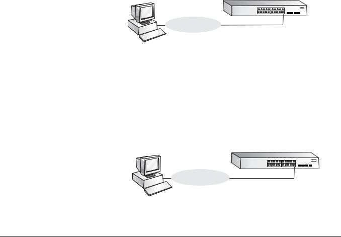
18 CHAPTER 1: GETTING STARTED
Figure 3 Web Interface Management over the Network
|
Workstation |
Switch |
|
|
Connect over Network |
||
|
via web browser |
||
|
Refer to “Setting Up Web Interface Management” on page 25. |
||
|
SNMP Management |
You can manage a switch using any network management workstation |
|
|
running the Simple Network Management Protocol (SNMP) as shown in |
||
|
Figure 4. For example, you can use the 3Com Network Director software, |
||
|
available from the 3Com website. |
||
|
Figure 4 SNMP Management over the Network |
||
|
SNMP Network Management |
Switch |
|
|
Workstation |
||
|
Connect over Network |
||
|
using SNMP |
||
|
Refer to “Setting Up SNMP Mana |
gement V1 or V2” on page 26. |
|
|
Switch Setup |
This section gives an overview of what you need to do to get your switch |
|
|
Overview |
set up and ready for management when it is in its default state. The |
|
|
whole setup process is summarized in Figure 5. Detailed procedural steps |
||
|
are contained in the sections that follow. In brief, you need to: |
■ Configure IP information manually for your switch or view the automatically configured IP information
■ Prepare for your chosen method of management
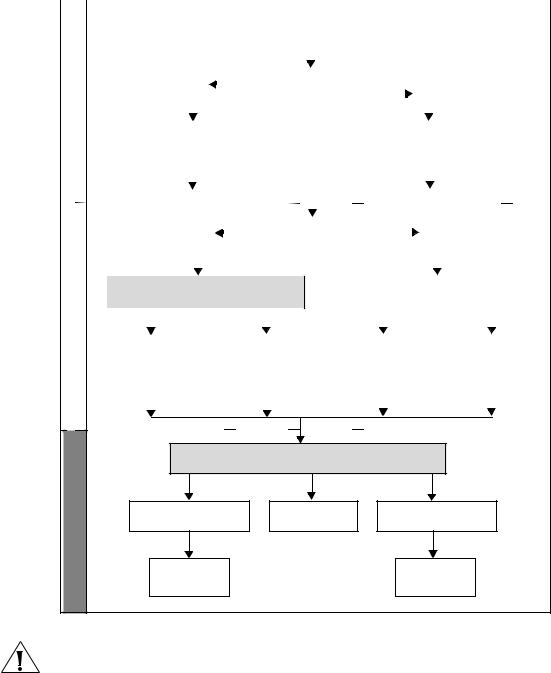
Figure 5 Initial Switch Setup and Management Flow Diagram
|
Power Up the Switch. |
||||||||||||||||||||||||||||||||||||||||||||
|
Setup |
Yes |
No |
||||||||||||||||||||||||||||||||||||||||||
|
Is a DHCP server present? |
||||||||||||||||||||||||||||||||||||||||||||
|
and Play |
||||||||||||||||||||||||||||||||||||||||||||
|
Plug |
IP Information is automatically |
The switch uses its default IP |
||||||||||||||||||||||||||||||||||||||||||
|
configured using DHCP |
information |
|||||||||||||||||||||||||||||||||||||||||||
|
See page 20 |
See page 20 |
|||||||||||||||||||||||||||||||||||||||||||
|
Yes |
Do you want to manually |
No |
|||||||||||||||||||||||||||||||||||||||||||||||||||
|
configure the IP information? |
|||||||||||||||||||||||||||||||||||||||||||||||||||||
|
Setup |
|||||||||||||||||||||||||||||||||||||||||||||||||||||
|
How do you want to connect to the Switch? |
How do you want to view the automatically |
||||||||||||||||||||||||||||||||||||||||||||||||||||
|
InformationIP |
Refer to the label on |
Connect to the |
|||||||||||||||||||||||||||||||||||||||||||||||||||
|
Connect to the |
Connect to a front panel |
||||||||||||||||||||||||||||||||||||||||||||||||||||
|
configured IP information? |
|||||||||||||||||||||||||||||||||||||||||||||||||||||
|
Initial |
console port and use |
port and use the Web |
the rear of the switch |
console port and use |
|||||||||||||||||||||||||||||||||||||||||||||||||
|
the Command Line |
Interface. |
which details the |
the Command Line |
||||||||||||||||||||||||||||||||||||||||||||||||||
|
Interface. |
See page 25 |
default IP address. |
Interface. |
||||||||||||||||||||||||||||||||||||||||||||||||||
|
See page 21 |
See page 23 |
||||||||||||||||||||||||||||||||||||||||||||||||||||
|
How do you want to manage your Switch? See page 17 |
||||
|
Feature Management |
Command Line Interface |
SNMP |
Web Interface |
|
|
(basic setup only) |
See page 26 |
|||
|
Connect using the |
Connect over the |
|||
|
console port. |
network. |
|||
|
See page 21 |
See page 26 |
CAUTION: To protect your switch from unauthorized access, you must change the default password as soon as possible, even if you do not intend to actively manage your switch. For more information on default users and changing default passwords, see “Default Users and Passwords” on page 27.

20 CHAPTER 1: GETTING STARTED
IP Configuration The switch’s IP configuration is determined automatically using DHCP, or manually using values you assign.
Automatic IP Configuration using DHCP
By default the switch tries to configure its IP Information without requesting user intervention. It tries to obtain an IP address from a DHCP server on the network.
Default IP Address If no DHCP server is detected, the switch will use its default IP information. The default IP address is 169.254.x.y, where x and y are the last two bytes of its MAC address.
Note: The switch’s default IP address is listed on a label located on the rear of the switch.
If you use automatic IP configuration it is important that the IP address of the switch is static, otherwise the DHCP server can change the switch’s IP addresses and it will be difficult to manage. Most DHCP servers allow static IP addresses to be configured so that you know what IP address will be allocated to the switch. Refer to the documentation that accompanies your DHCP server.
You should use the automatic IP configuration method if:
■your network uses DHCP to allocate IP information, or
■flexibility is needed. If the switch is deployed onto a different subnet, it will automatically reconfigure itself with an appropriate IP address, instead of you having to manually reconfigure the switch.
If you use the automatic IP configuration method, you need to discover the automatically allocated IP information before you can begin management. Work through the “Viewing IP Information using the Console Port” on page 23.
Manual IP Configuration
When you configure the IP information manually, the switch remembers the information that you enter until you change it again.
You should use the Manual IP configuration method if:
■You do not have a DHCP server on your network, or
■You want to remove the risk of the IP address ever changing, or
![]()
Using the Command Line Interface (CLI) 21
■ Your DHCP server does not allow you to allocate static IP addresses. (Static IP addresses are necessary to ensure that the switch is always allocated the same IP information.)
|
For most installations, 3Com recommends that you configure the switch |
|
|
IP information manually. This makes management simpler and more |
|
|
reliable as it is not dependent on a DHCP server, and eliminates the risk of |
|
|
the IP address changing. |
|
|
To manually enter IP information for your switch, work through the |
|
|
“Manually set the IP Address using the Console Port” on page 22. |
|
|
Using the |
You can access the switch through the Console port to manually set the |
|
Command Line |
IP address, or to view the IP address that was assigned automatically (for |
|
Interface (CLI) |
example, by a DHCP server). |
|
For more information about the CLI, refer to “3Com CLI Reference Guide” |
|
|
on page 195. |
|
|
Connecting to the |
This section describes how to connect to your switch through the |
|
Console Port |
Console port. |
Prerequisites
■A workstation with terminal emulation software installed, such as Microsoft Hyperterminal. This software allows you to communicate with the switch using the console port directly.
■Documentation supplied with the terminal emulation software.
■The console cable (RJ-45) supplied with your switch.
You can find pin-out diagrams for the cable in Appendix C on page 189.
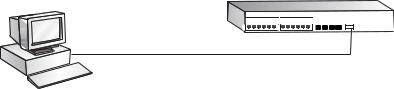
22 CHAPTER 1: GETTING STARTED
Connecting the Workstation to the Switch
1Connect the workstation to the console port using the console cable as shown in Figure 6.
Figure 6 Connecting a Workstation to the Switch using the Console Port
Workstation
(with terminal emulation Switch software installed)


 Console Port
Connection
Console Cable
Manually set the IP Address using the Console Port
To connect the cable:
aAttach the cable’s RJ-45 connector to the Console port of the switch.
bAttach the other end of the cable to the workstation.
2Open your terminal emulation software and configure the COM port settings to which you have connected the cable. The settings must be set to match the default settings for the switch, which are:
■38,400 baud (bits per second)
■8 data bits
■no parity
■1 stop bit
■no hardware flow control
Refer to the documentation that accompanies the terminal emulation software for more information.
3 Power up the switch. The Power on Self Test (POST) will be performed. The Switch 2916 and 2924 takes approximately one minute to boot.
You are now ready to manually set up the switch with IP information using the command line interface.
■You need to have the following information:
■IP address
■subnet mask
■default gateway
Using the Command Line Interface (CLI) 23
1Connect to the switch Console port as described in “Connecting to the Console Port” page 21.
2The command line interface login sequence begins as soon as the switch detects a connection to its console port. When the process completes, the Login prompt displays.
3At the login prompt, enter admin as your user name and press Return. The Password prompt displays.
4Press Return. If you have logged on correctly, Select menu option# should be displayed.
5Enter the IP address and subnet mask for the switch as follows: ipSetup xxx.xxx.xxx.xxx mmm.mmm.mmm.mmm
and then press Enter.
(Note: xxx.xxx.xxx.xxx is the IP address and mmm.mmm.mmm.mmm is the subnet mask of the switch.)
6Enter the logout command to terminate the CLI session.
The initial setup of your switch is now complete and the switch is ready for you to set up your chosen management method. See “Methods of Managing a Switch” on page 17.
Viewing IP This section describes how to view the automatically allocated IP Information using the information using the command line interface. The automatic IP
Console Port configuration process usually completes within one minute after the switch is connected to the network and powered up.
1Connect to the switch Console port as described in “Connecting to the Console Port” page 21.
The automatic IP configuration process usually completes within one minute.
2The command line interface login sequence begins as soon as the switch detects a connection to its console port.
3At the login prompt, enter admin as your user name and press Return.
4At the password prompt, press Return.If you have logged on correctly,
Select menu option# is displayed.

24 CHAPTER 1: GETTING STARTED
5Enter Summary to view a summary of allocated IP addresses. The following is an example of the display from the Summary command.
Select menu option# summary
|
IP Method: |
default |
|
IP address: |
169.254.99.51 |
|
Subnet mask: |
255.255.0.0 |
|
Runtime version: |
00_00_38 (date 01-Apr-2007 time 15:31:29) |
|
Bootcode version: |
1.0.0.12 (date 01-Apr-2007 time 17:44:52) |
|
Select menu option# |
The initial set up of your switch is now complete and the switch is ready for you to set up your chosen management method. See “Methods of Managing a Switch” on page 17.
For more information about the CLI, refer to “3Com CLI Reference Guide” on page 195.
If you do not intend to use the command line interface using the console port to manage the switch, you can logout, disconnect the serial cable and close the terminal emulator software.

Setting Up Web Interface Management 25
|
Setting Up Web |
This section describes how you can set up web interface management |
|
Interface |
over the network. |
|
Management |
Prerequisites |
|
■ Ensure you have already set up the switch with IP information as |
|
|
described in “Methods of Managing a Switch” on page 17. |
|
|
■ Ensure that the switch is connected to the network using a Category 5 |
|
|
twisted pair Ethernet cable with RJ-45 connectors. |
|
|
■ A suitable Web browser. |
|
|
Choosing a Browser |
|
|
To display the web interface correctly, use one of the following Web |
|
|
browser and platform combinations: |
Table 4 Supported Web Browsers and Platforms
|
Platform |
|||
|
Browser |
Windows 2000 |
Windows XP |
Windows Vista |
|
Internet Explorer 6 |
Yes |
Yes |
Yes |
|
Internet Explorer 7 |
Yes |
Yes |
Yes |
|
Firefox 1.5 |
Yes |
Yes |
Yes |
|
Firefox 2 |
Yes |
Yes |
Yes |
|
Netscape 8 |
Yes |
Yes |
Yes |
For the browser to operate the web interface correctly, JavaScript and Cascading Style Sheets must be enabled on your browser. These features are enabled on a browser by default. You will only need to enable them if you have changed your browser settings.
The switch’s Web interface supports both secure (HTTPS) and non-secure (HTTP) connections.

26 CHAPTER 1: GETTING STARTED
Web Management To manage a switch using the web interface over an IP network:
Over the Network
1Be sure that you know your switch’s IP address. See “IP Configuration” on page 20, and “Viewing IP Information using the Console Port” on page 23.
2Check that your management workstation is on the same subnet as your switch.
|
3 Check you can communicate with the switch by entering a |
ping |
|
command at the DOS or CMD prompt in the following format: |
c: ping xxx.xxx.xxx.xxx
(where xxx.xxx.xxx.xxx is the IP address of the switch)
If you get an error message, check that your IP information has been entered correctly and the switch is powered up.
4Open your web browser and enter the IP address of the switch that you wish to manage in the URL locator, for example, in the following format:
http://xxx.xxx.xxx.xxx
5At the login and password prompts, enter admin as your user name and press Return at the password prompt (or the password of your choice if you have already modified the default passwords).
The main Web interface page is displayed.
Setting Up SNMP You can use any network management application running the Simple Management V1 or Network Management Protocol (SNMP) to manage the switch. 3Com V2 offers a range of network management applications to address networks
of all sizes and complexity. See “3Com Network Management” on page 181.
Be sure the management workstation is connected to the switch using a port in VLAN 1 (the Default VLAN). By default, all ports on the switch are in VLAN 1.
To display and configure SNMP management parameters, refer to “Configuring SNMP” on page 135.
|
Default Users and Passwords |
27 |
Default Users and If you intend to manage the switch or to change the default passwords, Passwords you must log in with a valid user name and password. The switch has one
default user name. The default user is listed in Table 5.
|
Table 5 |
Default Users |
|
|
Default |
||
|
User Name Password |
Access Level |
|
|
admin |
(no password) |
Management — The user can access and change |
|
all manageable parameters |
||
Use the admin default user name (no password) to login and carry out initial switch setup.
Upgrading Software using the CLI
This section describes how to upgrade software to your Switch from the Command Line Interface (CLI).
Note: You can also upgrade the software using the switch Web user interface. See “Upgrade the Firmware Image” page 165. Bootcode can only be upgraded using the CLI.
1To download the runtime application file, enter: upgrade aaa.aaa.aaa.aaa rrr runtime
where aaa.aaa.aaa.aaa is the IP address of the TFTP server and rrr is the source runtime filename.
2To download the bootcode file, enter:
upgrade aaa.aaa.aaa.aaa bbb bootcode
where aaa.aaa.aaa.aaa is the IP address of the TFTP server and bbb is the source bootcode filename.
The bootcode firmware may not require upgrading for every software upgrade, therefore there may not be a new bootcode file to download.
3To set the switch to boot from the new software you have downloaded, enter the following:
reboot
The following prompt displays:
Are you sure you want to reboot the system (yes, no):
4 Enter yes and press Return. The system reboots the switch.

|
2 |
USING THE 3COM WEB INTERFACE |
This section provides an introduction to the user interface, and includes the following topics:
|
■ Starting the 3Com Web Interface |
||
|
■ Understanding the 3Com Web Interface |
||
|
■ |
Saving the Configuration |
|
|
■ |
Resetting the Device |
|
|
■ |
Restoring Factory Defaults |
|
|
■ Logging Off the Device |
||
|
Starting the 3Com |
This section includes the following topics: |
|
|
Web Interface |
■ |
Multi-Session Web Connections |
■ Accessing the 3Com Web Interface
Multi-Session Web The Multi-Session web connections feature enables 10 users to be Connections created and access the switch concurrently. Access levels provide read or
read/write permissions to users for configuring the switch. Users and access levels are described in Configuring System Access Section. Login information is always handled in the local database. A unique password is required of each user. Two access levels exist on the 3Com Web Interface:
■Management access level — Provides the user with read/write access. There is always one management level user configured for the switch. The factory default is be username: admin with no Password.
■Monitor access level — Provides the user with read-only access.
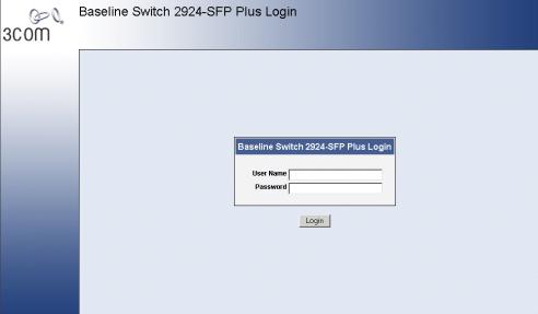
Starting the 3Com Web Interface 29
Accessing the 3Com This section contains information on starting the 3Com Web interface.
Web Interface
To access the 3Com user interface:
1Open an Internet browser.
2Enter the device IP address in the address bar and press Enter. The Enter
|
Network Password Page |
opens: |
Figure 7 Enter Network Password Page
3Enter your user name and password. The device default factory settings is configured with a User Name that is admin and a password that is blank. Passwords are case sensitive.
4Click Login. The 3Com Web Interface Home Page opens:
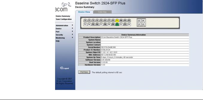
30 CHAPTER 2: USING THE 3COM WEB INTERFACE
Figure 8 3Com Web Interface Home Page
Understanding the
3Com Web
Interface
The 3Com Web Interface Home Page contains the following views:
■Tab View — Provides the device summary configuration located at the top of the home page.
■Tree View — Provides easy navigation through the configurable device features. The main branches expand to display the sub-features.
■Port Indicators — Located under the Device View at the top of the home page, the port indicators provide a visual representation of the ports on the front panel.
![]()
Understanding the 3Com Web Interface 31
Figure 9 Web Interface Components
The following table lists the user interface components with their corresponding numbers:
Table 6 Interface Components
|
View |
Description |
|
|
1 |
Tree View |
Tree View provides easy navigation through the configurable |
|
device features. The main branches expand to display the |
||
|
sub-features. |
||
|
2 |
Tab View |
The Tab Area enables navigation through the different device |
|
features. Click the tabs to view all the components under a |
||
|
specific feature. |
||
|
3 |
Web Interface |
Provides access to online help, and contains information about |
|
Information |
the Web Interface. |
|
This section provides the following additional information:
■Device Representation — Provides an explanation of the user interface buttons, including both management buttons and task icons.
■Using the Web Interface Management Buttons — Provides instructions for adding, modifying, and deleting configuration parameters.

32 CHAPTER 2: USING THE 3COM WEB INTERFACE
Device The 3Com Web Interface Home Page contains a graphical panel Representation representation of the device that appears within the Device View Tab.
To access the Device Representation:
1 Click Device Summary > Device View.
Figure 10 Device Representation
2By selecting a specific port with your mouse, you can view the port statistics.
For detailed information on configuring ports, please refer to “Configuring Ports” page 85.
Using the Web
Interface
Management Buttons
Configuration Management buttons and icons provide an easy method of configuring device information, and include the following:
|
Table 7 |
3Com Web Interface Configuration Buttons |
|
|
Button |
Button Name |
Description |
|
Clear Logs |
Clears system logs. |
|
|
Create |
Creates configuration |
|
|
entries. |
||
|
Apply |
Applies configuration |
|
|
changes to the device. |
||
|
Delete |
Deletes configuration |
|
|
settings. |
||
|
Table 8 |
3Com Web Interface Information Tabs |
|
|
Tab |
Tab Name |
Description |
|
Help |
Opens the online help. |
|
|
Logout |
Logs the user out and |
|
|
terminates the current |
||
|
session. |
||

|
Using Screen and Table Options |
33 |
|
Using Screen and |
3Com contains screens and tables for configuring devices. This section |
|
|
Table Options |
contains the following topics: |
|
|
■ |
Viewing Configuration Information |
|
|
■ |
Adding Configuration Information |
|
|
■ |
Modifying Configuration Information |
|
|
■ |
Removing Configuration Information |
Viewing Configuration Information
To view configuration information:
1Click Port > Administration > Summary. The Port Settings Summary Page opens:
Figure 11 Port Settings Summary Page

34 CHAPTER 2: USING THE 3COM WEB INTERFACE
Adding Configuration Information
User-defined information can be added to specific 3Com Web Interface pages, by opening the IP Setup Page.
For example, to configure IP Setup:
1 Click Administration > IP Setup. The IP Setup Page opens:
Figure 12 IP Setup Page
2Enter requisite information in the text field.
3Click Apply. The IP information is configured, and the device is updated.

|
Using Screen and Table Options 35 |
|
|
Modifying Configuration Information |
|
|
1 Click Administration System> |
Access > Modify. The System Access |
|
Modify Page opens: |
Figure 13 System Access Modify Page
2Modify the fields.
3Click Apply. The access fields are modified.

36 CHAPTER 2: USING THE 3COM WEB INTERFACE
Removing Configuration Information
1Click Administration > System Access > Remove. The System Access Remove Page opens:
Figure 14 System Access Remove Page
2Select the user account to be deleted.
3Click Remove . The user account is deleted, and the device is updated.

|
Saving the Configuration |
37 |
|
Saving the |
Configuration changes are only saved to the device once the user saves |
|
Configuration |
the changes to the flash memory. The Save Configuration tab allows the |
|
latest configuration to be saved to the flash memory. |
|
|
To save the device configuration: |
|
|
1 Click Save Configuration. The Save Configuration Page opens: |
|
|
Figure 15 Save Configuration Page |
A message appears: The operation saves your configuration. Do you wish to continue?
2Click OK. A Configuration is saved to flash memory successful message appears.
3Click OK. The configuration is saved.

38 CHAPTER 2: USING THE 3COM WEB INTERFACE
The Reset Page enables resetting the device from a remote location.
To prevent the current configuration from being lost, use the Save Configuration Page to save all user-defined changes to the flash memory before resetting the device.
To reset the device:
1 Click Administration > Reset. The Reset Page opens:
Figure 16 Reset Page
2Click Reboot. A confirmation message is displayed.
3Click OK. The device is reset, and a prompt for a user name and password is displayed.
Figure 17 User Name and Password Page
|
4 Enter a user name and password to |
reconnect to the web interface. |

|
Restoring Factory Defaults |
39 |
|
Restoring Factory |
The Restore option appears on the Reset Page. The Restore option |
|
Defaults |
restores device factory defaults. |
|
To restore the device: |
|
|
1 Click Administration > Reset . TheReset Page opens: |
|
|
Figure 18 Reset Page |
The Reset Page contains the following fields:
■Initialize with Current IP Address — Resets the device with the factory default settings, but maintains the current IP Address, subnet mask, and default gateway address.
■ Initialize with Default IP Address — Resets the device with the factory default settings, including the factory default IP Address.
2 Click the Initialize button. The system is restored to factory defaults.

40 CHAPTER 2: USING THE 3COM WEB INTERFACE
|
Logging Off the |
To log off the device: |
|
Device |
|
|
1 |
Click Logout. The Logout Page opens. |
|
2 |
The following message appears: |
|
3 Click OK. The 3Com Web Interface Home Page |
closes. |
![]()
|
This section contains information about viewing basic settings available |
|
|
from the Web interface home page, including the Device Summary page |
|
|
and the Color Keys page. |
|
|
Viewing Device |
The Device Summary Page displays general information, including the |
|
Settings |
system name, location, and contact, the system MAC address, System |
|
Object ID, System Up Time, and software, boot, and hardware versions. |
|
|
To view the Device Summary Settings: |
|
|
1 Click Device Summary. The Device Summary Page opens: |
|
|
Figure 19 Device Summary Page |
The Device Summary Page contains the following fields:
42CHAPTER 3: VIEWING BASIC SETTINGS
■Product Description — Displays the device model number and name
■System Name — Defines the user-defined device name. The field range is 0-160 characters.
■System Location — Defines the location where the system is currently running. The field range is 0-160 characters.
■System Contact — Defines the name of the contact person. The field range is 0-160 characters.
■Serial Number — Displays the device serial number.
■Product 3C Number — Displays the 3Com device 3C number.
■System Object ID — Displays the vendor’s authoritative identification of the network management subsystem contained in the entity.
■MAC Address — Displays the device MAC address.
■System Up Time — Displays the amount of time since the most recent device reset. The system time is displayed in the following format: Days, Hours, Minutes, and Seconds. For example, 41 days, 2 hours, 22 minutes and 15 seconds.
■Software Version — Displays the installed software version number.
■Boot Version — Displays the current boot version running on the device.
■Hardware Version — Displays the current hardware version of the device.
■Poll Now — Enables polling the ports for port information including speed, utilization and port status.

Viewing Color Keys 43
Viewing Color Keys The Color Key Page provides information about the RJ45 or SFP port status. To view color keys:
1 Click Device Summary > Color Key. The Color Key Pageopens:
Figure 20 Color Key Page
The Color Key Page contains the following fields:
■RJ45 — Displays the port status of the RJ45 connections which are the physical interface used for terminating twisted pair type cable.
■ SFP — Displays the port status of the Small Form Factor (SFP) optical transmitter modules that combine transmitter and receiver functions.
Table 9 describes the color and the port status:
Table 9 Color Key Definitions
|
Color |
Port Status |
|
White |
Unconnected. No link detected. |
|
Yellow |
Lower speed on 10/100/1000M port. |
|
Green |
Maximum speed 10/100/1000M RJ45 or RJ45 SFP. Indicates that a |
|
link was detected. |
|
|
Light Blue |
SX/LX SFP. Indicates that a link was detected. |
|
Light Gray |
Port has been set to inactive by User or Protocol. |
|
Dark Blue |
Port has been selected by user. |
|
Red |
Port or Transceiver has failed POST or Transceivers not recognized. |
|
4 |
MANAGING DEVICE SECURITY |
The Management Security section provides information for configuring system access, defining RADIUS authentication, port-based authentication and defining access control lists.
This section includes the following topics:
■Configuring System Access
■Defining RADIUS Clients
■Defining Port-Based Authentication (802.1X)
■Defining Access Control Lists
■Enabling Broadcast Storm

|
Configuring System Access |
45 |
Configuring System Network administrators can define users, passwords, and access levels for Access users using the System Access Interface. The Multi-Session web feature is
enabled on device and allows 10 users to be created and access the switch concurrently. Access levels provide read or read/write permissions to users for configuring the switch. Login information is managed in the local database. A unique password is required of each user. Two access levels exist on the 3Com Web Interface:
■Management access level — Provides the user with read/write access. There is always one management level user configured for the switch. The factory default is be user name: admin with no Password.
■Monitor access level — Provides the user with read-only system access.
This section contains the following topics:
■Viewing System Access Settings
■Defining System Access
■Modifying System Access
■Removing System Access

46 CHAPTER 4: MANAGING DEVICE SECURITY
Viewing System The System Access Summary Page displays the current users and access Access Settings levels defined on the device.
To view System Access settings:
1Click Administration > System Access > Summary. The System Access Summary Page opens:
Figure 21 System Access Summary Page
The System Access Summary Page contains the following fields:
■User Name — Displays the user name. The possible predefined field value is:
■ Admin — Displays the predefined Administrative user name.
■Access Level — Displays the user access level. The lowest user access
level is Monitor and the highest is Management .
■Management — Provides the user with read and write access rights.
■Monitor — Provides the user with read access rights.

|
Configuring System Access 47 |
||
|
Defining System |
The System Access Setup Page |
allows network administratorsdefineto |
|
Access |
users, passwords, and access levels for users using the System Access |
|
|
Interface. |
Monitor users have no access to this page.
1Click Administration > System Access > Setup. The System Access Setup Page opens:
Figure 22 System Access Setup Page
|
The System Access Setup Page |
contains the following fields: |
■User Name — Defines the user name.
■Access Level — Defines the user access level. The lowest user access
level is Monitor and the highest is Management .
■Management — Provides users with read and write access rights.
■Monitor — Provides users with read access rights.
■Password — Defines the user password. User passwords can contain up to 10 characters.
■Confirm Password — Verifies the password.
2Define the fields.
3Click Apply. The Users are created, and the device is updated.

48 CHAPTER 4: MANAGING DEVICE SECURITY
Modifying System The System Access Modify Page allows network administrators to modify Access users, passwords, and access levels using the System Access Interface.
Monitor users have no access to this page.
1Click Administration > System Access > Modify. The System Access Modify Page opens:
Figure 23 System Access Modify Page
The System Access Modify Page contains the following fields:
■User Name — Displays the user name.
■Access Level — Displays the user access level. The lowest user access level is Monitoring and the highest is Management.
■Management — Provides users with read and write access rights.
■Monitor — Provides users with read access rights.
■Password Modify — Changes a password for an existing user.
■Password — Defines the local user password. Local user passwords can contain up to 8 characters.
■Confirm Password — Verifies the password.
2 Select a User Name to be modified.
3Modify the fields.
4Click Apply. The User settings are modified, and the device is updated.

|
Configuring System Access |
49 |
Removing System The System Access Remove Page allows network administrators to Access remove users from the System Access Interface.
Monitor users have no access to this page.
To remove users:
1Click Administration > System Access > Remove. The System Access Remove Page opens:
Figure 24 System Access Remove Page
The System Access Remove Page contains the following fields:
■Remove User(s) — Select user(s) from the list below to be removed.
■User Name — Displays the user name.
■Access Level — Displays the user access velle. The lowest user access level is Monitoring and the highest is Management.
■Management — Provides users with read and write access rights.
■Monitoring — Provides users with read access rights.
2Select a Userto be deleted.
The last user with management access may not be deleted.
3Click Remove . TheUser is deleted, and the device is updated.

50 CHAPTER 4: MANAGING DEVICE SECURITY
Defining RADIUS Remote Authorization Dial-In User Service (RADIUS) servers provide
Clients additional security for networks. RADIUS servers provide a centralized authentication method for 802.1X.
The default parameters are user-defined, and are applied to newly defined RADIUS servers. If new default parameters are not defined, the system default values are applied to newly defined RADIUS servers.
Monitor users have no access to this page.
To configure the RADIUS client:
1Click Security > RADIUS Client > Setup. The Radius Client Setup Page opens:
Figure 25 Radius Client Setup Page
The Radius Client Setup Page contains the following fields:
■Primary Server — Defines the RADIUS Primary Server authentication fields.
■Backup Server — Defines the RADIUS Backup Server authentication fields.
■Host IP Address — Defines the RADIUS Server IP address.
- Инструкции и руководства
- Бренды
- 3com
- Baseline Switch 2924-SFP Plus
![]()
Модели
3CBLSG24-MEПоказать ещё
, 3CBLSG24-US, 3CBLSG24-CH
Скрыть
Техническая Спецификация (English)Техническая Спецификация (English)Техническая Спецификация (English)
Техническая Спецификация (3CBLSG24-ME)

-
- Размер:
- 733,1 КБ
-
- Страницы:
- 4
-
- Язык:
- English
Просмотреть
Техническая Спецификация (3CBLSG24-US)
-
- Размер:
- 733,1 КБ
-
- Страницы:
- 4
-
- Язык:
- English
Просмотреть
Техническая Спецификация (3CBLSG24-CH)
-
- Размер:
- 733,1 КБ
-
- Страницы:
- 4
-
- Язык:
- English
Просмотреть
Найди любой мануал:
Например: Sony VGN-FW460J/T
Вы можете бесплатно скачать Инструкция по эксплуатации для 3Com 2924-SFP.
Также вы сможете прочесть онлайн этот документ без скачивания.
Скачать Инструкция по эксплуатации для 3Com 2924-SFP
Тип файла
PDF
Размер
8.69 Mb
Кол-во страниц
216
Просмотров
3255
Читать онлайн Инструкция по эксплуатации для 3Com 2924-SFP (Страница 1)

Другие Сетевые коммутаторы (свитчи) 3Com 2924-SFP
Топ 3Com Сетевые коммутаторы (свитчи)
Вопросы
Ранее вы смотрели
Эта страница полезна для вас? Поделитесь ссылкой: