- Manuals
- Brands
- Access Manuals
- Synthesizer
- VIRUS C SERIES
- User manual
-
Contents
-
Table of Contents
-
Bookmarks
Quick Links
ACCESS VIRUS C SERIES
USER MANUAL OS5
ENGLISH VERSION
Related Manuals for Access VIRUS C SERIES
Summary of Contents for Access VIRUS C SERIES
-
Page 1
ACCESS VIRUS C SERIES USER MANUAL OS5 ENGLISH VERSION… -
Page 3
©2002 Access Music GmbH, Germany. VIRUS is a trademark of Access Music GmbH. All other trademarks contained herein are the property of their respective owners. All features and specifications subject to change without notice. Written by Christoph Kemper, Uwe G. Hönig, Wiland Samolak and Marc Schlaile. -
Page 4: Table Of Contents
Content Handling…………… 44 All about the memory ……….. 47 The Modulation Matrix and Soft Knobs….48 Random Patch Generator……..50 Categories…………52 The Effects Section……….52 IMPORTANT SAFETY REMARKS Audio Inputs …………53 Internal Audio Routing ……….54 Additional functions ……….55 PROLOGUE SYNTHESIS PARAMETERS OSCILLATORS …………
-
Page 5
ACCESS VIRUS OS5 Problems Related to Parameter Control ….144 MAIN EDIT MENU Arrangement Dump — The Sound in the Song..145 Common ………….. 96 Unison Mode…………99 Punch Intensity ……….100 TIPS AND TRICKS Envelope Sustain Time……..100 Analog Inputs…………. 100 All abouts Inputs………. -
Page 6
INDEX INDEX …………..192… -
Page 7: Important Safety Remarks
Important Safety Remarks…
-
Page 8
Important Safety Remarks Please read all notes carefully before you power OPERATION the device up. A few fundamental rules on han- • Don’t set beverages or any other receptacle dling electrical devices follow. containing liquids on the device. • Make sure the device is placed on a solid base. -
Page 9
These can damage the surface of the housing. FITNESS FOR PURPOSE This device is designed exclusively to generate low-frequency audio signals for sound engi- neering-related purposes. Any other use is not permitted and automatically invalidates the warranty extended by Access Music Electronics GmbH. -
Page 10
Important Safety Remarks… -
Page 11: Prologue
Prologue…
-
Page 12
CHAPTER 3 Prologue Dear VIRUS Owner, delay unit that lets you create high-quality re- verb effects and rhythmic delay taps. Delay Congratulations on your choice, the new VI- time can be synced up to MIDI clock. RUS. You have purchased a cutting-edge syn- thesizer that comes fully loaded with several With the benefit of two external audio inputs, revolutionary features. -
Page 13
ACCESS VIRUS OS5 LFOs can run independently or in sync. A sponds just as smoothly as analog synthesizers number of keyboard trigger options enable you did prior to the introduction of digital sound start LFO waveshapes with variable phase storage lengths at the beginning of a note and/or to cy- cle once only, like an envelope. -
Page 14
CHAPTER 3 Prologue… -
Page 15: Introduction
Introduction…
-
Page 16: The Virus
CHAPTER 4 Introduction í THE VIRUS section is a brick that builds on a preceding brick and interlocks with those next to it. You want your knowledge base to be a sound struc- ture so you won’t run into problems when you This section provides deliberate, step-by-step find one of the “bricks”…
-
Page 17
ACCESS VIRUS OS5 The Virus MASTER VOLUME and so on, simply use the PARAMETER/BANK buttons to step from one program bank to an- Controls the overall volume of the VIRUS. This other. control determines the volume of the signal pair piped through Output 1 before it is converted You’ll find that some sound programs are la-… -
Page 18
CHAPTER 4 Introduction SOUND CATEGORIES lect these combination programs via the VALUE button. The VIRUS features “only” 128 MULTI To help you find the type of SINGLE sound you PROGRAMs, so you don’t have to switch back are looking for more quickly, the Virus operating and forth between banks they way you just did system lets you define so-called „categories“… -
Page 19: The Amplifier Envelope
ACCESS VIRUS OS5 The Amplifier Envelope í THE AMPLIFIER ENVELOPE Take a look at the display of the VIRUS to gain an impression of the difference between these two values. It shows two numeric values when you dial a pot: at the left you can see the value Long-term exposure to this sound will definitely…
-
Page 20: The First Filter
CHAPTER 4 Introduction í to others, i.e. the effectiveness of a control fea- THE FIRST FILTER ture is altered, modified or even negated com- pletely by other related functions. Now we will take a look at a component of a synthesizer that is generally regarded as the The final pot, RELEASE, determines the speed most important functional unit as it enables…
-
Page 21: Filter Modulation
ACCESS VIRUS OS5 Filter Modulation Now locate the FILT 1 MODE switch, which is resonance up. Experiment by varying the RES- also located in the FILTERS section. It enables ONANCE setting in the different operating you to select a filter operating mode from the…
-
Page 22
CHAPTER 4 Introduction highly desirable that your box is silent. With the For your next experiment set the amplifier enve- filter envelope, the situation is somewhat differ- lope so that you hear a constant level when you ent: It always starts at the Cutoff value that you press and hold a note. -
Page 23: The Saturation Stage
ACCESS VIRUS OS5 The Saturation Stage wards the negative control range, the KEY position (12 o’clock) determines the volume of FOLLOW effect is reversed. With the VIRUS, the filter section’s input signal. The portion of you will encounter this feature — intensity control…
-
Page 24
CHAPTER 4 Introduction The technical design of this second filter is 1 (we’ll explain Cutoff 2 a bit later). Set Cutoff to identical to the first, so we won’t discuss it in a medium or middle value and turn the RESO- as much detail as we did the first filter. -
Page 25
ACCESS VIRUS OS5 The Second Filter In other words, at the center position (12 Now experiment with the diverse filter modes o’clock) the manually selected frequency of Fil- and listen closely to the effect of the parame- ter-2 is identical to that of Filter-1. When you ro-… -
Page 26: Filter Routing
CHAPTER 4 Introduction í FILTER ROUTING The final parameter we’ll discuss for the time being is FILTER ROUTING. This feature offers several filter routing options which allow you to operate the filters in series, i.e. patch one after the other in the signal chain, or in parallel, which means side by side in the signal chain: — SER-4 The filters are switched in series;…
-
Page 27: The First Oscillator
ACCESS VIRUS OS5 The First Oscillator í THE FIRST OSCILLATOR The filters, with the exception of a notch filter or band stop (BS), trim the far reaches of the tonal spectrum, so for instance a signal sounds mud- dier after it has been routed through a low pass To this point, we have turned our attention ex- filter.
-
Page 28
CHAPTER 4 Introduction What you need is a sound-shaping option for the portion of a signal that a filter allows to OSCILLATORS OSCILLATORS pass. And of course you also need a tool for de- termining the pitch of a signal. In synthesizers, both of these tasks are executed by oscillators. -
Page 29: The Second Oscillator
ACCESS VIRUS OS5 The Second Oscillator í (PW = pulse width) pot, PROVIDED THE SHAPE THE SECOND OSCILLATOR POT IS SET TO A POSITION IN THE RIGHT HALF OF ITS CONTROL RANGE (LATER THAN 12 O’CLOCK). Rotate the WAVE SEL/PW pot…
-
Page 30
Locate and activate the SYNC button in the oscillator that lets you create further oscillations OSCILLATORS section (the LED must illumi- and spectra. You can access the parameters of nate). The synchronization function forces Os- this oscillator, which are described in a later cillator 2 to restart its wave cycle at the same chapter, via the OSCILLATOR EDIT menu. -
Page 31: The Third Oscillator
ACCESS VIRUS OS5 The Third Oscillator í THE THIRD OSCILLATOR Now we’ll take a closer look at the final control element, the SUB OSC pot: It controls the vol- ume of the fourth oscillator, the so-called Sub- Oscillator, which always operates an octave The VIRUS also has a third main oscillator, below Oscillator 1.
-
Page 32: The Lfos
CHAPTER 4 Introduction the ring modulator. Be sure to check out what In the VIRUS, both of these tasks are executed the ring modulator does when you select a sine by a so-called LFO (low frequency oscillator) wave for Oscillator 1 and 2. that oscillates at frequencies below the audible range.
-
Page 33
In order to change this set- saturation stage is not used, you will only ting, you must access the second SELECT but- hear tremolo. The position within the signal ton which works in conjunction with fi ve chain (at the input of the filter section) has… -
Page 34
(AMOUNT). erate faster LFO rates. As result, when you press and hold several notes you will hear all In the WAVE setting, you have access to 64 kinds of substantially different periodic fluctua- LFO waveshapes. Select these in the display tions. -
Page 35: The Mod Section
Select button. This no Edit menu is selected. For each SOFT gives you access to the Virus modulation ma- KNOB, you can choose a short description from trix. The six ASSIGN entries (selectable via the a list in the menu, and this will be saved as part SELECT button) represent six freely definable…
-
Page 36: Volume And Panorama Position
CHAPTER 4 Introduction í í VOLUME AND PANORAMA VELOCITY POSITION Velocity is one of the preferred modulation sources of keyboard players: A light key attack You probably noticed that the many of the generates a low velocity value for the given sound shaping options available in the VIRUS note, a heavy touch generates a high velocity occasionally influence the volume level.
-
Page 37: Unison Mode
ACCESS VIRUS OS5 Unison Mode í UNISON MODE where two voices are played for every note. In the ”OFF” position, one voice per note is played. When we talked about the oscillators, we men- tioned that by subtly detuning signals, you can beef up sounds and achieve string-like sounds.
-
Page 38: The Effects
EFFECTS and a DELAY/ clock, DELAY/REV TIME controls the time ex- REVERB block. This gives you access to Distor- pressed as a note value (1/16, 1/8, etc.). tion, Phaser and Chorus effects as well as De- lay and Reverb.
-
Page 39
ACCESS VIRUS OS5 The Effects — RATEREDUCER Variable reduction of the phaser‘s own LFO. The other three parameters sampling rate; generates digital aliasing ef- affect the general sound of the phaser: FRE- fects. QUENCY determines the average frequency of resonant peaks, STAGES is the number of reso- — LOWPASS 1-pole lowpass filter;… -
Page 40: The Arpeggiator
CHAPTER 4 Introduction the DEPTH i.e. modulation intensity of the LFO. Please note that signal paths in the Virus Cho- DELAY / REVERB DELAY / REVERB rus/Flanger are stereo throughout: The stereo position and any panorama modulation or ster- eo spread values are preserved in the proc- 12 12 12 12 12 12…
-
Page 41: More To Come
ACCESS VIRUS OS5 More to ComeSoundDiver Virus from the computer (Mac or PC). Even if you pre- software. SoundDiver has an integrated Help fer to control your Virus with its own knobs and system, which includes extensive information buttons most of the time, SoundDiver still has…
-
Page 42
CHAPTER 4 Introduction… -
Page 43: Concept And Operation
Concept and Operation…
-
Page 44: Operating Modes
The PART buttons don’t actually change sounds, they simply set The VIRUS provides access to up to 1024 SIN- the user interface of the VIRUS to the desired GLE sounds. Next to the 256 RAM sounds PART.
-
Page 45
ACCESS VIRUS OS5 Operating Modes the PART numbers are identical to the MIDI In MULTI mode, you have one MULTI edit buffer channels of the PARTs. Now when you work in and 16 SINGLE edit buffers for the PARTs at MULTI SINGLE mode, the VIRUS responds as if your disposal. -
Page 46: Master Clock And Midi-Clock
CHAPTER 5 Concept and Operation í MASTER CLOCK AND MIDI- GRAMs are ignored. Instead, all involved SIN- GLE PROGRAMs are controlled via the same CLOCK clock generator. Its CLOCK TEMPO is saved in the MULTI PROGRAM (as are the settings for the global delay effect).
-
Page 47
ACCESS VIRUS OS5 Handling that you can access these directly — especially If you press the PARAMETER buttons briefly, while you are playing!. In just a few cases the you can scroll through the parameters con- control features have dual functions. -
Page 48
CHAPTER 5 Concept and Operation (mostly zero). This pertains to unipolar parame- — ISNAP The modal controls (for instance ters (value range of 0 to 127) as well as bipolar those whose functions apply to one oscillator parameters (value range of -64 to +63). or LFO at a time) will be in SNAP mode, whereas all the others will be in JUMP mode. -
Page 49: All About The Memory
Press STORE. You when you turn a knob. then gain access to the STORE menu. There you can use the PARAMETER buttons to move — ON The lower row of the display is being among the individual letters in the lower name overwritten by the parameter’s value.
-
Page 50: The Modulation Matrix And Soft Knobs
CHAPTER 5 Concept and Operation Compare mode lets you hear the unedited so it is not lost even after several program sound that was originally stored in this memory change messages (as long as none of the other slot. Press EDIT or UNDO repeatedly to switch programs are edited in any way).
-
Page 51
For your target parameters, you can wise only available from within the menus. The chose from among virtually all sound parame- destination parameters are defined in the Edit… -
Page 52: Random Patch Generator
CHAPTER 5 Concept and Operation For each SOFT KNOB, you can choose a short description from a list in the menu, and this will MULTISINGLE MULTISINGLE be saved as part of the SINGLE program. In Play mode, this will appear in the display – sim- ply to remind you of what each SOFT KNOB does while you are playing your Virus.
-
Page 53
ACCESS VIRUS OS5 Random Patch Generator The RANDOM PATCH GENERATOR is ac- This simply means that it isn’t bent radically so cessed by pressing the RANDOM button. The that, for example, the given sound can still be results of randomization are sent directly to the played “tonally”. -
Page 54: Categories
Classic, Arpeggiator, Effects, Drums, Percus- sion, Input, Vocoder, Favourite 1, Favourite 2, Favourite 3 For every SINGLE program and every PART, you can access up to six different stereo effects individually. You’ll find these effects – RING- MULTISINGLE MULTISINGLE MODULATOR, DISTORTION, ANALOG BOOST, EQUALIZER, PHASER and CHORUS –…
-
Page 55: Audio Inputs
ACCESS VIRUS OS5 Audio Inputs í AUDIO INPUTS In this case, you can also use the UNISON Pan Spread parameter to determine the basic width of the panorama and UNISON LFO Phase to shift the LFO phase position be- You can also opt to use external audio signals tween the voices.
-
Page 56: Internal Audio Routing
CHAPTER 5 Concept and Operation ically switches to this level indicator mode when ic). You can then process the signal patched in the selected SINGLE program accesses the ex- to this PART via the aux bus exactly the same ternal audio inputs. The LEDs will flash rapidly way you would process conventional analog to indicate that the inputs are being overloaded.
-
Page 57: Additional Functions
ACCESS VIRUS OS5 Additional functions In contrast to the majority of other effects, the such as the modulation wheel, channel volume delay/reverb section is not available individually and pitch bender are reset to the default set- for each PART. Instead, it processes the signals tings.
-
Page 58
CHAPTER 5 Concept and Operation… -
Page 59: Synthesis Parameters
Synthesis Parameters…
-
Page 60: Oscillators
CHAPTER 6 Synthesis Parameters Oscillators 1 is a sine wave; No. 2 a triangle, the remainder of the waves feature different combinations of frequencies. • When the SHAPE value is higher than that of í The following section lists all parameters in the center position, then WAVE SEL/PW deter- the VIRUS, each with a brief definition or expla- mines the pulse width: At the far left position…
-
Page 61: Oscillator (Edit-Menu)
ACCESS VIRUS OS5 Oscillator (Edit-Menu) í FM AMOUNT OSCILLATOR (EDIT-MENU) Controls the frequency modulation intensity of the second oscillator by the first. Depending on the selected FM AMOUNT and the interval be- tween the oscillators, the frequency modulation OSCILLATOR-1 WAVE generates everything from slightly to radically Selects among of 64 spectral waveshapes.
-
Page 62
CHAPTER 6 Synthesis Parameters OSCILLATOR-2 WAVE — NOISE The noise generator is the FM source (see also NOISE Color). Excellent for drum Selects among of 64 spectral waveshapes. This sounds. parameter is identical to WAVE SEL/PW (see appropriate section) when SHAPE (see appro- — INPUT Here the mono or stereo signal from priate section) is set to the left half of its control external analog inputs or from an internal aux… -
Page 63
ACCESS VIRUS OS5 Oscillator (Edit-Menu) FILT ENV -> FM in for Oscillator 2 apply to Oscillator 3, with one exception – DETUNE. This parameter runs It determines the intensity at which the filter en- counter to that of Oscillator 2. -
Page 64: Sub Oscillator
CHAPTER 6 Synthesis Parameters OSCILLATOR-3 SEMITONE junction with Oscillator 3 and PHASE INIT, you can create prominent overtones that are initiat- Transposes Oscillator 3 in semitone steps. Con- ed at the beginning of a note. trol range: +/-4 octaves. (Not available if OS- CILLATOR 3 MODE = “OFF”…
-
Page 65: Filter
first filter, the second filter or both filters. In con- filters have the same CUTOFF frequency. In trast to virtually all other modulation intensity FILTER EDIT Menu, you can access CUTOFF parameters in the VIRUS, ENV AMOUNT is a LINK ON/OFF to sever the link between CUT- unipolar parameter.
-
Page 66: Filter Envelope
CHAPTER 6 Synthesis Parameters FILT 1 MODE & FILT 2 MODE SELECT only determines if the knob in question sends its value to the first filter, second filter or Selects the operating mode of the indicated fil- both filters. ter: — LP The low pass filter suppresses frequen- cies higher than the CUTOFF frequency (see appropriate section) and allows the lower fre-…
-
Page 67: Filter-Edit-Menu
ACCESS VIRUS OS5 Filter-Edit-MenuFilter Envelope longer it takes for the envelope to fall from its ”Digital” curve as much as 24 decibels. A spe- current level to the minimum level, when the key cial feature of the VIRUS’ SATURATION stage is is released.
-
Page 68
CHAPTER 6 Synthesis Parameters — RATEREDUCER Continuous reduction of — SER-6 The filters are switched in series; Fil- the digital sampling rate; generates digital ter-1 has four poles (24dB), Filter-2 has two aliasing. poles (12dB) so the overall slope is equivalent to six poles (36dB). -
Page 69
ACCESS VIRUS OS5 Filter-Edit-MenuFilter Envelope at this pitch. In the FILTER EDIT menu you have FILTER-2 CUTOFF LINK the option of freely defining the base note under Switches the knob and the parameter CUTOFF KEYTRACK BASE. 2 (see appropriate section) back and forth be-… -
Page 70
CHAPTER 6 Synthesis Parameters note; if you turn it counter-clockwise to the left (towards FALL), then the level drops off at an in- creasing rate towards the minimum level; If you turn the knob clockwise to the right (towards RISE), the level rises at an increasing rate to maximum. -
Page 71: Envelopes
í The Sustain Time parameter can be access- ed from the main Edit menu as well as from the DECAY filter EDIT menu..
-
Page 72: Mixer
CHAPTER 6 Synthesis Parameters Mixer NOISE VOLUME The volume of the noise generator. As with the ring modulator, the volume is idependent off the OSC VOL parameter. OSC BALANCE Determines the balance between the Oscillators RINGMODULATOR VOLUME 1 and 2 volume level. The ring modulator multiplies the output of both oscillator 1 and 2 to create interesting sounds with rich enharmonic overtones.
-
Page 73: Lfo And Modmatrix
ACCESS VIRUS OS5 LFO (Panel)Filter Envelope LFO and ModMa- AMOUNT (LFO-1) After selecting LFO 1 (via the SELECT button) trix you can use the lower SELECT button to scroll down through the modulation destinations for LFO 1. If you press and hold the EDIT button at the same time, you can scroll in the other direc- tion.
-
Page 74
CHAPTER 6 Synthesis Parameters If the modulation intensity for the selected des- AMOUNT (LFO-3) tination is not „0“, its LED stays lit after you quit After selecting LFO 3 (via the SELECT button) the menu. you can use the lower SELECT button to scroll down through the modulation destinations for 01111111111111111112 LFO 3. -
Page 75: Lfo (Edit Menu)
ACCESS VIRUS OS5 LFO (Edit Menu)Filter Envelope Between the two positions Filter-1 and FILTER- LFO-1CLOCK 2 you will find the position Filter-1+2, which lets When you set it to OFF, the LFO oscillates in the you jointly control the modulation intensities of normal manner, independently of the global both oscillators.
-
Page 76
CHAPTER 6 Synthesis Parameters — SQUARE Contour modulates the pulse LFO-2 ENV MODE width of the square wave. Activates an operating mode in which the LFO oscillates like an envelope: The LFO cycles — WAVES Contour ”zooms” into the wave, once only following the start of the note;… -
Page 77
ACCESS VIRUS OS5 LFO (Edit Menu)Filter Envelope MIDI clock. When the LFO is synced up to the LFO-2TRIGGER PHASE master clock, you can also select the desired Selects the position in the wave cycle — i.e. the note value via the LFO RATE knob. -
Page 78
CHAPTER 6 Synthesis Parameters LFO-3 FADE IN — SINGLE In polyphonic mode, all voices are assigned the same LFO. This parameter lets you automatically initiate a delayed fade-in the LFO3 modulation that you set up via OSC AMOUNT (see the section above). -
Page 79
ACCESS VIRUS OS5 LFO (Edit Menu)Filter Envelope For your SOURCEs, you have two different types of modulation sources to chose from. The The control range of the source may be limited first type comprises external MIDI controllers via the AMOUNT values or inverted so that the… -
Page 80
CHAPTER 6 Synthesis Parameters ASSIGN 1 AMOUNT Controls the intensity of ASSIGN 3 DESTINATION 2 Selects the sec- the first modulation allocation. ond modulation destination for the third modu- lation assignment. 01111111111111111112 1 ASSIGN 1 ASSIGN 3 AMOUNT 2 Controls the intensity Amount +10≤… -
Page 81
ACCESS VIRUS OS5 LFO (Edit Menu)Filter Envelope ASSIGN 6 SOURCE Selects the modulation source for the first modulation assignment. ASSIGN 6 DESTINATION Selects the modu- lation destination for the first modulation as- signment. ASSIGN 6 AMOUNT Controls the intensity of… -
Page 82: Arpeggiator Edit
CHAPTER 6 Synthesis Parameters Arpeggiator Edit ARPEGGIATOR OCTAVES Controls the ascending transposition of arpeg- gios by octaves. Control range: 1 to 4 octaves. The controls in the Arpeggiator section only 01111111111111111112 consists of two buttons: ARP ON switches it on 1 ARPEGGIATOR or off, and EDIT opens up the arpeggiator Octaves…
-
Page 83
ACCESS VIRUS OS5 LFO (Edit Menu)Filter Envelope When SWING is set to the lowest value (50%), PO (see the section on CLOCK TEMPO). More- the interval between the individual sixteenth over, the clock generator can be synced up to beats is identical and the length of an eighth the external MIDI Clock. -
Page 84: The Internal Effects
CHAPTER 6 Synthesis Parameters The internal — LIGHT, SOFT, MIDDLE, HARD Different an- alog distortion curves with different charac- teristics and intensities. Effects — DIGITAL Digital distortion with hard clipping. — SHAPER Sine characteristic curve with sev- eral wave cycles. With the Shaper, you can The Effects menu contains the parameters of drastically warp signals.
-
Page 85: Chorus (Panel)
ACCESS VIRUS OS5 Chorus (Panel)Filter Envelope The Effects section of the VIRUS features a fur- The LFO modulates the left and right sides of ther distortion module called SATURATION. Its the Chorus signal antiphase, which generates a design is identical to that of the DISTORTION true stereo effect.
-
Page 86: Phaser (Panel)
CHAPTER 6 Synthesis Parameters FEEDBACK The pure phaser signal is generated by frequen- cy-dependent phase shifting (PHASER Fre- Controls the amount of feedback in the Chorus. quency) and pitch modulation of the phaser’s On the chorus, FEEDBACK lets you boost spe- own LFOs (PHASER Rate and Depth).
-
Page 87: Delay / Reverb
ACCESS VIRUS OS5 Delay / ReverbFilter Envelope DEPTH SPREAD Controls the intensity of the Phaser frequency Use SPREAD to increase or decrease the dis- modulation by the LFO. tance between the notches and peaks in the frequency spectrum. In other words, here you can adjust bandwidth of the phaser effect.
-
Page 88: Delay / Reverb (Panel)
DELAY TIME (DELAY) MODE program. This is the absolute delay time of the delay ef- However in MULTI MODE, all 16 PARTs access fect in milliseconds (ms). Use it to determine the the same Delay or Reverb effect. In this case,…
-
Page 89: Delay / Reverb (Menu)
ACCESS VIRUS OS5 Delay / Reverb (Menu)Filter Envelope DELAY FEEDBACK (DELAY MODE) In a real room, walls don’t reflect high frequen- cies as well as they do lower frequencies, an ef- Controls the amount of feedback of the Delay. fect that can be likened to natural low-pass filtering of the sound.
-
Page 90
CHAPTER 6 Synthesis Parameters — REV+FEEDB1 This the VIRUS’ trademark room simulation. Here you can use the FEED- The unique sonic character of the PATTERN de- BACK control to generate pre-delay feed- lay algorithms is due to — among other things — back. -
Page 91
ACCESS VIRUS OS5 Delay / Reverb (Menu)Filter Envelope DELAY COLOR ing eingestellt werden oder auf Null gestellt werden, da die LFO-Modulation das Timing des A filter is placed in the delay effect’s output, Delays beeinflusst that also effects the feedback path. It can be… -
Page 92
CHAPTER 6 Synthesis Parameters REVERB TYPE a variable filter that can act as a low-pass filter (negative control range) as well as a high-pass This parameter lets you select from among four filter (positive control range). For a natural- different room sizes to create the type of simu- sounding room simulation, you should always lation that you want. -
Page 93
ACCESS VIRUS OS5 Delay / Reverb (Menu)Filter Envelope REVERB parameters, the amount of pre-delay CLOCK TEMPO in the global clock generator has a decisive impact on our perception of the (refer to this section). In this case, the absolute size of a room. -
Page 94: Vocoder
CHAPTER 6 Synthesis Parameters í VOCODER TUNE Controls the frequency range of ANALOG BOOST. For more information on the Vocoder see “The 01111111111111111112 Vocoder of the VIRUS” on page 131 1 ANALOG BOOST Tune 32≤ 61111111111111111154 í ANALOG BOOST í This effect produces the typical bass response EQUALIZER of analog synthesizers.
-
Page 95
ACCESS VIRUS OS5 EqualizerFilter Envelope MID-EQ FREQUENCY Center frequency of the midrange bandpass fil- ter. Please note that this can actually be set an- ywhere between 20 Hz and 24 kHz, i.e. it is not necessarily restricted to what is usually consid- ered “midrange”. -
Page 96
CHAPTER 6 Synthesis Parameters… -
Page 97: Main Edit Menu
Main Edit Menu…
-
Page 98: Common
CLOCK LFO 2, CLOCK LFO 3, DELAY CLOCK, and #11 (Expression). However, these are not see the respective sections). stored with the SINGLE program.. In MULTI MODE, you can also access PART VOLUME 01111111111111111112 (see appropriate section), which provides fur- 1 CLOCK ther volume reserves (headroom).
-
Page 99
ACCESS VIRUS OS5 Common PANORAMA continue to run through their phases when you play other notes (Single Trigger mode); Determines the Panorama position of the SIN- Portamento is only active when you play GLE program. Dieser Parameter kann auch legato. -
Page 100
CHAPTER 7 Main Edit Menu ( s e e “ T h e V I R U S k c a n d t h e i n d i g o ” o n — LIN Starting from the 0 value, (center posi- page 126). -
Page 101: Unison Mode
ACCESS VIRUS OS5 Unison Mode — NOTE Adaptive Control Smoothing is carried DETUNE out continuously (smoothed), but jumps in Slightly detunes the voices involved in UNISON steps when a new note is played. mode. 01111111111111111112 01111111111111111112 1 COMMON 1 UNISON SmoothMode On≤…
-
Page 102: Punch Intensity
CHAPTER 7 Main Edit Menu PHASE pertains to all LFOs and does not impair mathematical infinity symbol, then the SUSTAIN the phase response of the LFOs within either of level remains constant through to the end of the the two voices. note;…
-
Page 103
ACCESS VIRUS OS5 Envelope Sustain TimeAnalog Inputs gate does. If you turn FILTER KEY FOLLOW The signal source that you select here is used up, the input signal is filtered by a different fil- for both the vocoder and the ring modulator in ter frequency depending on the key you the effects section. -
Page 104: Follower (Envelope-Follower)
SELECT before you can establish a signal con- nection between the two PARTS. Several PARTs ENVELOPE FOLLOWER ATTACK can simultaneously access the external input or (Knob: FILTER ATTACK) It controls the attack the internal aux paths via INPUT SELECT. rate of the envelope follower. With this parame- ter, you can determine how fast the envelope follower will respond to the rise in signal level.
-
Page 105: Second Output/Surround
ACCESS VIRUS OS5 Second Output/SurroundAnalog Inputs tudes of both signals, which provides the fre- SELECT quencies’ sums and differences. The more This parameter controls the balance of levels harmonics in the incoming signal, the more dis- between the normal and the second audio out- tinct the modulation.
-
Page 106: Velocity
CHAPTER 7 Main Edit Menu you opt to use one of the aux buses as a sec- VELOCITY OSC 2 SHAPE ond output, the aux bus can also serve as an FX Determines the intensity of the VELOCITY con- loop. You can route the aux signal to a PART trol for the second oscillator’s SHAPE parame- and have the PART process this signal further.
-
Page 107
ACCESS VIRUS OS5 VelocityAnalog Inputs VELOCITY FILT 1 ENV AMT VELOCITY RESONANCE 2 Determines the intensity of the VELOCITY control for the reso- Determines the intensity of the VELOCITY con- nance of Filter-2. trol for the modulation of Filter-1’s cutoff fre- quency by the filter envelope. -
Page 108: Sound Category
SOFT KNOB mode to ”Single” be- ometers which are particularly useful for giving cause this is the most versatile mode. When direct access to parameters which are other- you select a SINGLE sound whose SOFT KNOB wise only available from within the menus. The mode is set to ”Single”, this setting is of course…
-
Page 109
ACCESS VIRUS OS5 Soft Knob-1/2Analog Inputs and is stored along with it. The entry is only ac- SOFT KNOB-1 NAME tive when SOFT KNOB-1 MODE is set to SIN- For each SOFT KNOB, you can choose a short GLE. When SOFT KNOB-1 SINGLE is set to… -
Page 110
CHAPTER 7 Main Edit Menu ate globally and are accessible in the SYSTEM menu at any time irrespective of the given oper- ating mode. -
Page 111: Multi Mode & System Setup
Multi Mode & System Setup…
-
Page 112: Multi Mode Parameters
CHAPTER 8 Multi Mode & System Setup Multi Mode PART DETUNE Fine-tunes the PART. Parameters 01111111111111111112 1 B36 101BASS RP PartDetune +10≤ í Please bear in mind the PART- and/or 61111111111111111154 MULTI-related parameters described in the fol- lowing are available in MULTI mode only. PART VOLUME SELECT BANK Controls the volume level of the PART.
-
Page 113
ACCESS VIRUS OS5 tion between the two PARTS. Several PARTs If the selected output is monophonic, then the can simultaneously access the external input or Panorama settings and modulations in the the internal aux paths via OUTPUT SELECT. sound program are inactive. -
Page 114
CHAPTER 8 Multi Mode & System Setup date a new voice. When you set the Priority of a HIGH KEY PART to ”High”, the VIRUS will not ”steal” any Determines the highest MIDI note that the PART notes from the voices of this PART. Use this pa- responds to. -
Page 115
ACCESS VIRUS OS5 PRG CHG ENABLE Switches a given PART’s MIDI receive mode for MIDI Program Change messages ON and OFF. 01111111111111111112 1 B36 101BASS RP ProgChange Ena≤ 61111111111111111154 í The following parameter groups of the MULTI-EDIT-Menu have already been de-… -
Page 116: System
CHAPTER 8 Multi Mode & System Setup SYSTEM This simply means that it isn’t bent radically so that, for example, the given sound can still be played “tonally”. As you increase the values for PAR DEPTH, oth- The following parameters are global parameters er parameters that have a greater impact on the and are accessible at any time in the SYSTEM timbre of the sound are changed.
-
Page 117
ACCESS VIRUS OS5 Keyboard KEYBOARD MODE KEYBOARD TRANSPOSE The Keyboard Mode function enables you to The VIRUS keyboard can be transposed in select OneChannel or Multichannels and this is semitones. Note that this transposition applies how it works: to the output of the keyboard, it is not generat- ed within the Virus itself. -
Page 118: Input
CHAPTER 8 Multi Mode & System Setup í PEDAL-1 INPUT Selects the MIDI controller number of the first pedal. The default value is CC#64 (sustain ped- al). INPUT DIRECT THRU 01111111111111111112 The stereo signal patched to the external inputs 1 KEYB PEDAL-1 can be routed to the dual-jack Output 1 without being processed in any manner.
-
Page 119: Midi
ACCESS VIRUS OS5 MIDI This is a global parameter, i.e. it affects all in- INPUT PHONO volved PARTs and INPUT DIRECT THRU (see Since record players have a characteristic fre- paragraph below). It is not stored along with the quency response, we equipped the Virus Rack SINGLE PROGRAM.
-
Page 120
CHAPTER 8 Multi Mode & System Setup CONTROL LoPage / HiPage. This function Once you have selected the desired data sends the SINGLE program that you are cur- type, the dump is initiated via STORE. rently processing (the contents of the Edit buffer). -
Page 121
ACCESS VIRUS OS5 MIDI — VERIFY Compares an incoming MIDI dump — INT+MIDI All types of control operations are to the memory content of the VIRUS. It sent directly to the VIRUS sound generation checks if a dump was recorded properly on components and simultaneously to MIDI Out. -
Page 122
CHAPTER 8 Multi Mode & System Setup ARPEGGSEND MIDI VOLUME ENABLE This parameter determines whether or not (ON Globally switches the reception of Volume data or OFF, respectively) the arpeggiator sends the (Controller #7) on (ENA) or off (DIS). notes it generates to the MIDI Out. This function is a feasible option only when you want to ad- 01111111111111111112 dress further sound generators via MIDI. -
Page 123: System
ACCESS VIRUS OS5 System MIDI DEVICE ID polypressure data is disabled on the receive side; if you set it to ”Contr”, both polypressure Here you can enter the identification number for and SysEx data are received. system exclusive data transfer. To enable com- munication between two VIRUS units — i.e.
-
Page 124
CHAPTER 8 Multi Mode & System Setup To emulate the behavior of earlier operating sy- — WARN Patches and Multis can be stored. stem version, you need to switch ON the opti- Furthermore the “SOUND EDITED! Remem- ber storing” alert in the multimode is disa- bled. -
Page 125
ACCESS VIRUS OS5 System ly to reflect the current SEND value of the Im SNAP-Mode tritt rechts neben der Zahl ein phaser. To avoid unwanted value jumps in ®-symbol hinzu, das anzeigt, in welche Rich- these parameters, you can activate the Show… -
Page 126
CHAPTER 8 Multi Mode & System Setup — ON The contents of the display are overwrit- — AUX2 Much like when the setting «ExtIn» is ten when you turn a knob; the original menu enabled, you can have the two LFO Rate does not reappear in the display. -
Page 127: The Keyboard Versions Of The Virus
The keyboard versions of the Virus…
-
Page 128: The Virus Kc And The Indigo
CHAPTER 9 The keyboard versions of the Virus í THE VIRUS KC AND THE (directly as well as through the sequencer), nor do you want the internal sound generator to INDIGO play along when you are trying to play the sounds on a different synthesizer.
-
Page 129
ACCESS VIRUS OS5 The VIRUS kc and the indigo pots still control only the VIRUS — and nothing the other control features. These multiple as- else. Only if you want to record the control data signment capabilities enable you to create very in a sequencer, or definitely want to influence… -
Page 130: The Keyboard-Modes
CHAPTER 9 The keyboard versions of the Virus Switch and control pedals are available in your Transpose (-64…+63). The KEYBOARD Trans- local music store. The only suitable control ped- pose can be switched in octaves by the als are the typical synthesizer control pedals TRANSPOSE buttons on the user panel as well.
-
Page 131
ACCESS VIRUS OS5 The Keyboard-Modes are checked and assigned in the keyboard and hereby taken into consideration which keyboard not in the sound generator. The idea behind this area the part has (LowKey, HighKey), and each option is that it is an easy and elegant way to in- individual part-transposition (PartTranspose). -
Page 132
CHAPTER 9 The keyboard versions of the Virus The keyboard sends its signals to MIDI-Out, but Here an overview of the keyboard version’s not to the sound generator of the correspond- special parameters: ing part. This enables you to control an external machine with the appropriate keyboard zone. -
Page 133: The Vocoder Of The Virus
The Vocoder of the VIRUS…
-
Page 134: Vocoder
filtered or combined (see above). The vocoder substitutes the whole filter section of a The sound characteristic is being rendered into single sound. Therefore, you can access the the new sound by two cascades of bandpass vocoder’s parameters via the filter section on filters: The modulator signal is being send…
-
Page 135
ACCESS VIRUS OS5 Vocoder THE MODULATOR BANK This cascade of bandpass filters split the fre- quency spectrum of the modulator into slices, quite similar to the way a studio frequency ana- lyser would. THE ENVELOPE FOLLOWER The level at the output of each bandbass filter is measured by the modulator bank. -
Page 136: The Parameters Of The Virus Vocoder
CHAPTER 10 The Vocoder of the VIRUS í THE PARAMETERS OF THE OSC VOL VIRUS VOCODER DEFAULT: 0 (MIDDLE) OSC VOL adjusts the output level of the vocod- er. This is independent of the signal source (which can be assigned using the vocoder í…
-
Page 137
ACCESS VIRUS OS5 The parameters of the VIRUS Vocoder FREQUENCY SPREAD A linear shift of the modulator bank’s central fre- quencies against the carrier bank, results in KNOB: KEYFOLLOW pitch-shifting and ”mickey mouse” effects. DEFAULT: +63 (RIGHT) CUTOFF2 creates an offset of the modulator to the carrier bank. -
Page 138
CHAPTER 10 The Vocoder of the VIRUS VOCODER RELEASE Several vocoder related parameters can be modulated by LFO-1 and LFO-2 KNOB: FILTER DECAY DEFAULT: 0 (LEFT) — LFO 1 RESO 1+2 modulates the bandpass filter quality of the modulator and carrier The release time of the envelope follower. -
Page 139: Notes About The Vocoder
ACCESS VIRUS OS5 Notes about the vocoder: í NOTES ABOUT THE VOCODER: can be used at once to drive the vocoder’s in. Using FILTER BALANCE you can balance the level of the original signal. The vocoder can also be controlled by any part The effect section (chorus, delay) and the out- of the multimode.
-
Page 140
CHAPTER 10 The Vocoder of the VIRUS… -
Page 141: The Virus And Sequencers
The VIRUS and Sequencers…
-
Page 142
M0, but this now appears in a form which gives nection also makes sense for Virus C or Virus you full access to all 16 individual sounds Rack users: All Virus controls and parameters (switchable using the Part buttons). Just like in… -
Page 143
ACCESS VIRUS OS5 using the channel of the currently selected track mands – in contrast to system exclusive data – instead. This way you will hear the same sound are transported very swiftly. Beyond that, during recording and playback. they’re easy to edit graphically in all standard sequencer programs. -
Page 144
CHAPTER 11 The VIRUS and Sequencers solved by splitting up its parameters into three only type of remote control option that is active Parameter PAGEs for data transport purposes. – you get exclusively system exclusive control, Each of these three PAGEs can contain up to as it were. -
Page 145
ACCESS VIRUS OS5 Bear in mind that the sequencer doesn’t indi- Application: Parameter jumps are carried out cate the parameters addressed via the control without glitches. This option is ideal when you features of the VIRUS by their names; instead, it want to create gating and similar effects (e.g. -
Page 146: Problems Related To Parameter Control
CHAPTER 11 The VIRUS and Sequencers í Side effect: When you’re playing polyphoni- PROBLEMS RELATED TO cally, parameter jumps also affect notes that PARAMETER CONTROL were played previously and are still sounding when a new note is played. The Control Smooth mode parameter setting is considered a component part of a SINGLE If you enjoy experimenting with recording pa- sound and is thus stored with it.
-
Page 147: Arrangement Dump — The Sound In The Song
ACCESS VIRUS OS5 Arrangement Dump — The Sound in the Song however, you change or replace the sound in sure that the VIRUS plays the song back using the VIRUS at some point? The program change the right sounds, we recommend that you posi- message in the song would call up the wrong tion stored data prior to the song.
-
Page 148
CHAPTER 11 The VIRUS and Sequencers the arrangement rather than the actual SIN- You’ll find a summary of all dump options and GLEs, the sounds of all active PARTs are sent an explanation of these in the comprehensive separately (for more info on this, see the section overview of parameters, specifically, under the on MULTIMODE). -
Page 149: Tips And Tricks
Tips and tricks…
-
Page 150: All Abouts Inputs
When you press the two VALUE buttons simul- ble for administering the 16 PARTs. Conse- taneously, the parameter is reset to its original quently, you can’t access SINGLE program value. You can increase the rate at which pa- parameters directly here. Beyond that, you’re…
-
Page 151: About The Delay/Reverb
ACCESS VIRUS OS5 About the Delay/Reverb OSC VOL / INPUT est possible clean signal level to the analog-to- digital converters of the VIRUS so that they will When one of the two INPUT modes is activated, deliver the best possible performance. You…
-
Page 152: The Virus As An Effect Device
CHAPTER 12 Tips and tricks patch just the pure effect signal of a MULTI Part its external inputs to any available aux send bus through as you would it you were using a con- or effect send on your mixer or to the individual ventional dry/wet effect knob.
-
Page 153: Oscillators
ACCESS VIRUS OS5 Oscillators trols the filters cutoff frequency and creates a typical «Autowah» effect, whereby the filter is opened according to the drumloop’s volume (respectively its beats). In addition to this, or as 12 12 12 12 12 12…
-
Page 154
CHAPTER 12 Tips and tricks these spectra can be modulated continuously via envelopes and LFOs. FM and SYNC will of OSCILLATORS OSCILLATORS course also work with the 64 digital waveforms. 12 12 12 12 WAVE WAVE OSCILLATOR 3 / PW / PW SEMITONE SEMITONE… -
Page 155: Filters
ACCESS VIRUS OS5 Filters Like all other oscillators, the level of Oscillator 3 36 dB/oct. As you turn the knob to the left, is controlled via OSC VOL.. you’re fading Filter-2 out and consequently steadily reducing the slope until you arrive at 24 dB/oct.
-
Page 156: Lfos
CHAPTER 12 Tips and tricks TION) within a wide range of 12 decibels, , with- the shape of which you can vary from linear to out increasing the volume level. At 24 decibels, exponential by means of LFO Curve in the LFO the control range of the «Digital»…
-
Page 157: Volume Control
ACCESS VIRUS OS5 Volume Control In contrast to ENV mode (which is available in- case, the filters will fade out freely since their dependently of KEY TRIG PHASE), an LFO with output signals are not affected by the FILT GAIN KEY TRIG PHASE will continue to oscillate once volume modulation.
-
Page 158: Assign And The Soft Knobs
CHAPTER 12 Tips and tricks ble-click on the two Transpose buttons (Panic ed and sent back to the VIRUS. Reasonably function) resets Channel Volume and Expres- enough, you should set the controller number sion to this unit value. for the SOFT KNOB under SOFT KNOB-1/2 Single because this setting (like the ASSIGN settings) is stored with the SINGLE program and doesn’t apply to all SINGLEs (as is the case…
-
Page 159: Midi
ACCESS VIRUS OS5 MIDIHow to modulate the Vocoder parameters For example: To modulate the CARRIER CEN- Set the MIDI DUMP RX parameter to Force To TER FREQUENCY you need to choose FILTER- Edit Buffer. With this option, sounds that would…
-
Page 160: How To Install Updates
CHAPTER 12 Tips and tricks BANK/PROGRAM CHANGE VIA SYSEX Parts to High, you’re defeating the purpose of this parameter. In this case, it wouldn’t have any A bank or program change can be initiated via a effect since the priority of all voices is the same. SysEx command.
-
Page 161
ACCESS VIRUS OS5 How to install UpdatesHow to modulate the Vocoder parameters INSTALLING A NEW OPERATING SYS- There’s no danger of a flawed MIDI transmis- sion burning faulty software into the VIRUS’ memory. When the device receives MIDI data, The Virus C, kc and indigo use an identical op- this information is first buffered in the delay… -
Page 162
[Store] on VIRUS 2; the software will now be burned to the Flash Rom. SOFTWARE UPDATES Access is known for their policy of free software updates. Simply download the latest VIRUS op- erating system from our web site and enjoy new VIRUS features. -
Page 163: Appendix
Appendix…
-
Page 164: System Exclusive Data
CHAPTER 13 Appendix í SYSTEM EXCLUSIVE DATA When disabled (HiPage=SysEx), the VIRUS only sends and receives SysEx Parameter Change on Page B. When enabled (HiPage=PolyPrs), the VIRUS sends MIDI Poly Pressure on param- eter movements, and receives both MIDI Poly VIRUS MIDI SYSTEM EXCLUSIVE Pressure and SysEx Parameter Change on Page B.
-
Page 165
ACCESS VIRUS OS5 System Exclusive Data CONTROL CHANGE MESSAGE (ONLY SYSTEM-EXCLUSIVE-MESSAGE PAGE A) Start of System Exclusive Manufacturer ID 1 Status byte, Access Music Electronics c=MIDI channel Manufacturer ID 2 Parameter Number 0..127 Access Music Electronics (see parameter list Page A) -
Page 166
CHAPTER 13 Appendix Example: F0,00,20,33,01,10,70,05,28,5F,F7 Program Number Set Cutoff on Part 6 to decimal 0..127 [256 multi bytes] value 95. (10: device ID omni; 70: page A, 05: Checksum part 6; 28: parameter Cutoff, 5F: decimal value optional {F0,00,20,33,01,dd,11,bb,mm,[256 multi bytes],cs,F7} SINGLE DUMP í… -
Page 167
ACCESS VIRUS OS5 System Exclusive Data MULTI REQUEST GLOBAL REQUEST [message]= [message]= Multi Request Global Request Bank Number 00:Multi Edit buffer; {F0,00,20,33,01,dd,35,F7} 01:Multi Bank Program Number 0..127 TOTAL REQUEST [message]= {F0,00,20,33,01,dd,31,bb,mm,F7} Total Request í {F0,00,20,33,01,dd,36,F7} When bank number 00, the dump destina- tion is the Multi Edit buffer. -
Page 168: Parameter Descriptions
CHAPTER 13 Appendix í PARAMETER DESCRIPTIONS Class Name Range Value Text PAGE A Bank Select 0..3 Bank A..D Modulation Wheel Breath Controller Contr 3 Foot Controller Portamento Time 0..127 Data Slider Channel Volume 0..127 Balance Contr 9 A 10 Panorama 0..127 -64..0..+63: Left..Center..Right…
-
Page 169
ACCESS VIRUS OS5 Parameter Descriptions Class Name Range Value Text A 27 Osc2 FM Amount 0..127 A 28 Osc2 Sync 0..1 0:Off 1:On A 29 Osc2 Filt Env Amt 0..127 -64..+63 A 30 FM Filt Env Amt 0..127 -64..+63 A 31 Osc2 Keyfollow 0..127… -
Page 170
CHAPTER 13 Appendix Class Name Range Value Text A 59 Amp Env Attack 0..127 A 60 Amp Env Decay 0..127 A 61 Amp Env Sustain 0..127 A 62 Amp Env Sustain Time 0..127 -64..+63: Fall..Infinite..Rise A 63 Amp Env Release 0…127 A 64 Hold Pedal… -
Page 171
ACCESS VIRUS OS5 Parameter Descriptions Class Name Range Value Text A 88 Cutoff1 Lfo2 Amount 0..127 -64..+63 A 89 Cutoff2 Lfo2 Amount 0..127 -64..+63 A 90 P a n o r a m a L f o 2 0..127 -64..+63… -
Page 172
CHAPTER 13 Appendix Class Name Range Value Text A118 a,ms,n Delay Lfo Shape 0..5 0:Sine 1:Tri 2:Saw 3:Square 4:S&H 5:S&G .. Reverb Damping 0..127 A119 a,ms,n Delay Color 0..127 -64..+63 A122 Keyb Local 0..1 0:Off 1:On A123 All Notes Off… -
Page 173
ACCESS VIRUS OS5 Parameter Descriptions Class Name Range Value Text PAGE B Arp Mode 0..6 0:Off 1:Up 2:Down 3:Up&Down 4:As- Played 5:Random 6:Chord Arp Pattern Select 0..31 Arp Octave Range 0..3 Arp Hold Enable 0..1 0:Off 1:On Arp Note Length 0..127… -
Page 174
CHAPTER 13 Appendix Class Name Range Value Text B 34 b,Vb Osc FM Mode 0..12 0:Pos-Tri 1:Tri 2:Wave 3:Noise 4:In L 5:In L+R .. B 35 Osc Init Phase 0..127 0:Off 1..127 B 36 Punch Intensity 0..127 B 38 b,Vb Input Follower Mode 0..9 0:Off 1:In L 2:In L+R … -
Page 175
ACCESS VIRUS OS5 Parameter Descriptions Class Name Range Value Text B 67 Assign2 Source see Assign Sources List B 68 Assign2 Destination1 see Assign Destinations List B 69 Assign2 Amount1 0..127 -64..+63 B 70 Assign2 Destination2 see Assign Destinations List… -
Page 176
CHAPTER 13 Appendix Class Name Range Value Text B100 b,Vb Distortion Curve 0..6 0:Off 1:Light 2:Soft 3:Middle 4:Hard 5:Digital .. B101 b,Vb Distortion Intensity 0..127 B102 b,Vc Assign 4 Source 0..27 see Assign Sources List B103 b,Vc Assign 4 Destination 0..122 see Assign Destinations List B104… -
Page 177
ACCESS VIRUS OS5 Parameter Descriptions Class Name Range Value Text Page C m,np Multi Name Char1 32..127 ASCII m,np Multi Name Char2 32..127 ASCII m,np Multi Name Char3 32..127 ASCII m,np Multi Name Char4 32..127 ASCII m,np Multi Name Char5 32..127… -
Page 178
CHAPTER 13 Appendix Class Name Range Value Text C 69 Keyb Pedal 2 Contr see Keyboard Destination List C 70 Keyb Pressure Sens 0..127 0:Off 1..127 C 72 Part Enable 0..1 0:Off 1:On C 73 Part Midi Volume Ena- 0..1 0:Off 1:On C 74 Part Hold Pedal Enable… -
Page 179
ACCESS VIRUS OS5 Parameter Descriptions Class Name Range Value Text C115 Soft Knob-2 Midi 0..127 C116 Expert Mode 0..2 0:0ff 1:On 2:All C117 Knob Mode 0..5 0:Off 1:Jump 2:Snap 3:Relative (…) C118 Memory Protect 0..1 0:0ff 1:On 2:Warn C120 Soft Thru 0..1… -
Page 180: Multi Dump Table
CHAPTER 13 Appendix í MULTI DUMP TABLE NAME RANGE VALUE TEXT 0..3 Internal 4..13 Multi Name Charac- 32..127 ASCII ters 1..10 Internal Multi Clock Tempo 0..127 6 3 . . 1 9 0 Multi Delay Mode 0..1 0:Off 1:On Multi Delay Time 0..127 Multi Delay Feedback 0..127…
-
Page 181
ACCESS VIRUS OS5 Multi Dump Table NAME RANGE VALUE TEXT 128..1 P a r t Detune 0..127 -64..+63 1..16 144..1 P a r t Part Volume 0..127 -64..+63; 0=Unity Gain 1..16 160..1 P a r t Midi Volume Init 0..127 Off, 1..127… -
Page 182: Classes
CHAPTER 13 Appendix NAME RANGE VALUE TEXT Part State Bitfield: Bit 0 Part Enable 0:Off 1:On Bit 1 Part Midi Volume Ena- 0:Off 1:On Bit 2 Part Hold Pedal Ena- 0:Off 1:On Bit 3 Keyb To Midi 0:Off 1:On Bit 4 Internal Bit 5 Note Steal Priority…
-
Page 183
ACCESS VIRUS OS5 Classes í MS: MULTI/SINGLE PARAMETER W h e n i n The VIRUS can be switched between Multi Single Mode, the parameter is received and Mode and Single Mode by parameter C123 Part stored with the Single Sound.When in Multi Number. -
Page 184: Mod Matrix Sources
CHAPTER 13 Appendix í MOD MATRIX SOURCES All sources of the SOFT KNOBS-1/2 PitchBnd ChanPres ModWheel Breath Contr3 Foot Data Balance Contr 9 Express Contr 12 Contr 13 Contr 14 Contr 15 Contr 16 HoldPed PortaSw SostPed AmpEnv FiltEnv Lfo 1 Lfo 2 Lfo 3 VeloOn…
-
Page 185: Mod Matrix Destinations
ACCESS VIRUS OS5 Mod Matrix Destinations í MOD MATRIX DESTINATIONS All destinations of the Modulation Matrix PatchVol ChannelVol Panorama Transpose Portamento Osc1Shape Osc1PlsWdh Osc1WavSel Osc1Pitch Osc1Keyflw Osc2Shape Osc2PlsWdh Osc2WavSel Osc2Pitch Osc2Detune Osc2FmAmt Osc2EnvAmt FmEnvAmt Osc2Keyflw OscBalance SubOscVol OscMainVol NoiseVol Cutoff…
-
Page 186: Soft Knob Destinations
CHAPTER 13 Appendix í SOFT KNOB DESTINATIONS All destinations of the SOFT KNOBS-1/2 ModWheel Breath Contr3 Foot Data Balance Contr9 Expression Contr12 Contr13 Contr14 Contr15 Contr16 PatchVolume ChannelVolume Panorama Transpose Portamento UnisonDetune UnisonPanSprd UnisonLfoPhase ChorusMix ChorusRate ChorusDepth ChorusDelay ChorusFeedback EffectSend DelayTime(ms) DelayFeedback DelayRate…
-
Page 187: Midi Implementation Chart
ACCESS VIRUS OS5 MIDI Implementation Chart í MIDI IMPLEMENTATION CHART Function Transmitted Recocgnized Remarks Basic Default Channel Changed 1-16 1-16 Default Mode Messages Altered ************ Note 0-127 0-127 Number True Voice ************ 0-127 Velocity Note ON Note OFF After- Key’s Touch Ch‘s…
-
Page 188: Fcc Information (U.s.a)
FCC requirements. Modifications not ex- tailer authorised to distribute this type of prod- pressly approved by ACCESS MUSIC ELEC- uct. TRONICS may void your authority, granted by the FCC, to use this product.
-
Page 189: Fcc Information (Canada)
ACCESS VIRUS OS5 FCC Information (CANADA) í FCC INFORMATION (CANADA) The digital section of this apparatus does not exceed the „Class B“ limits for radio noise em- missions from digital apparatus set out in the radio interference regulation of the Canadian Department of Communications.
-
Page 190: Declaration Of Conformity
Hersteller abgegeben: EG-KONFORMITÄTSERKLÄRUNG This declaration has been given responsibly to the manufacturer: Für das folgend bezeichnete Erzeugnis/ For the following named product Access Music Electronics GmbH ACCESS VIRUS SYNTHESIZER Am Stadion 10 45659 Recklinghausen Germany MODEL C / KC / INDIGO Recklinghausen, 1.2.2002…
-
Page 191: Garantie Bestimmung
GARANTIE BESTIMMUNG Ferner müssen folgende Voraussetzungen er- füllt sein: — Das Gerät befindet sich in der Originalverpak- access Music Electronics leistet Garantie für al- kung oder zumindest gleichwertiger Verpak- le nachweisbaren Material- und Fertigungsfeh- kung. ler für eine Dauer von 24 Monaten ab Verkauf oder Aushändigung an den Endverbraucher.
-
Page 192: Warranty
The following stipulations also apply: — Ensure the unit is sent in its original package or one of equal quality. The access music electronics warranty covers all defects in material and workmanship for a — Include a detailed description of the defect period of six months from the date of original and a copy of the purchase receipt.
-
Page 193
Index… -
Page 194
Index Index CATEGORIES CHANNEL VOLUME CHORUS CHORUS DELAY CHORUS DEPTH ADAPTIVE CONTROL SMOOTHING CHORUS DIR/EFF AFTERTOUCH CHORUS FEEDBACK AMPLIFIER CHORUS RATE AMPLIFIER ENVELOPE CHORUS SHAPE ANALOG BOOST CLOCK RECEIVE ANALOG BOOST INTENSITY CLOCK RX ANALOG BOOST TUNE COMPARE ANALOG INPUTS CONNECTIONS ARPEGGIATOR CUTOFF… -
Page 195
ACCESS VIRUS OS5 EDIT BUFFER HIGH KEY EDIT MENU HIGH PAGE EFFECT HIGH PASS EFFECT SECTION HOLD PEDAL EFFECT SEND ENVELOPE ENVELOPE FOLLOWER ENVELOPE MODE INPUT ENVELOPE POLARITY INPUT BOOST EQUALIZER INPUT DIRECT THRU EXPRESSION CONTROLLER INPUT GAIN INPUT LEVEL INDICATOR… -
Page 196
Index LFO TRIGGER OSC DETUNE LFO TRIGGER PHASE OSC FILT ENV -> FM LOCAL OFF OSC FILT ENV -> PITCH LOW KEY OSC FM AMOUNT LOW PAGE OSC FM MODE LOW PASS OSC KEY FOLLOW OSC MODE OSC PHASE INIT OSC SEMITONE OSC SYNC MASTER CLOCK… -
Page 197
ACCESS VIRUS OS5 PRIORITY SOFT KNOBS PROGRAM CHANGE ENABLE SOFT THRU PULSE WIDTH SOFTWARE UPDATES PUNCH INTENSITY SOUNDDIVER STORE SUB OSC VOLUME SUB OSCILLATOR SURROUND RANDOM AMOUNT SURROUND BALANCE RANDOM PATCH GENERATOR SURROUND SELECT RATEREDUCER SUSTAIN RECTIFIER SYNC RELEASE SYSEX IMPLEMENTATION… -
Page 198
Index WARRANTY…
Login
User Registration
Registration pending: further action is required.
Please check your emails. You’ll get an email with a activation link to complete the registration.
User Registration
Registration pending: further action is required.
Your request will be processed soon.
User Registration
Registration complete.
Sign in
Password reset
Enter your email address and we will send you a link to reset your user account.
Password reset
We have sent you an e-mail with a password reset link from no-reply@kemper-amps.com. If you don’t receive an e-mail after a couple of minutes, please check your SPAM folder.
Password reset
Enter your new password.
Password reset
Password reset complete. Your password has been changed. Please login with the new credentials.
Specifications:
|
Accompanying Data:
Access VIRUS C SERIES Synthesizer PDF Operation & User’s Manual (Updated: Monday 28th of November 2022 12:02:08 AM)
Rating: 4.6 (rated by 7 users)
Compatible devices: Virus Rack XL, VIRUS CLASSIC, VIRUS|POWERCORE, Wavedrum mini, PSR-E273, CN35, Stylophone S2, Virus TI.
Recommended Documentation:
Access VIRUS C SERIES: Text of Operation & User’s Manual
(Ocr-Read Version Summary of Contents, UPD: 28 November 2022)
-
26, 24 CHAPTER 4 Introduction of the notch decreases; in other words more frequencies on both sides of the fil- ter frequency are allowed to pass.
… -
84, 82 CHAPTER 12 Audio Routing THE AUDIO OUTPUTS In MULTI mode, you can choose a mono or stereo audio output in the OUTPUT Select menu independently for every PART. In contrast to the majority of other effects, the delay/reverb section is not available individually for each PART. Instead, it processes the signals of the PARTs collectively. You can, however, control t…
-
139, ACCESS VIRUS RACK 137 Edit Section/Menu ture an infinitely variable control range – ergo, you have more than 100 modula- tion destinations at your disposal. If you haven’t selected a source for one of the ASSIGN options (SOURCE = OFF), the subordinate parameters will not be displayed. In addition to the three ASSIGN options, the user interface features – as discussed earlier – a fre…
-
93, ACCESS VIRUS RACK 91 Additional Functions Reset Function If you get the impression that the VIRUS is behaving unstable or indeed strange, we suggest you perform a system reset. Holding the PARAMETER LEFT button while switching the VIRUS on, performs a system reset. No data will be lost dur- ing this procedure, although some glo- bal system settings as ”Global Channel…
-
121, ACCESS VIRUS RACK 119 EFX Section/Encoder will become more prominent when you set a short decay time and a long pre- delay time. 01111111111111111112 1 REVERB Feedback 50≤ 61111111111111111154 Delay sThe following parameters are only available when you’re working with DELAY algorithms. DELAY RATE Determines the speed of the Delay LFO. 01111111111111111112 1 DELAY Ra…
-
56, 54 CHAPTER 5 Concept and Operation OPERATING MODES In the Virus you can select from two ba5sic operating modes, SINGLE MODE and MULTI MODE. In SINGLE MODE, the Virus is able to generate a single sound program only. All 16 voices, all effects and all control features (with the exception of the MULTI button) function in conjunction with this one sound program. You might say a SI…
-
100, 98 CHAPTER 16 The Parameters FILT ENV -> FM It determines the inten- sity at which the filter envelope controls the frequency modulation (FM AMOUNT). This as well as the previous parameter are ”relics” from the prede- cessor model of the Virus. Modulations such as these may also be implemented via the Modulation Matrix (see the sec- tion ”ASSIGN” below). 01111111111111111112 1 O…
-
50, 48 CHAPTER 4 Introduction UNISON MODE When we talked about the oscillators, we mentioned that by subtly detuning signals, you can beef up sounds and achieve string-like sounds. The Virus is equipped with features that allow you to take this type of tonal manipulation a step further. On of these is the so-called UNISON MODE. It enables you to initiate two or more voice…
-
193, ACCESS VIRUS RACK 191 LFOs LFO Mode You can set the LFO Mode parameter so that the LFOs are polyphonic or mono- phonic. In Poly mode, the LFOs of several voices have different phase positions. This lets you create complex modulations for pad-like sounds, and puts an end to the sonic monotony of a “wobbly” monophonic LFO. In SINGLE mode, one LFO c…
-
62, 60 CHAPTER 6 Operation PARAMETER SELECTION AND DATA ENTRY The parameters of the Virus Rack are controlled via the five encoder knobs. The functions of this row of knobs may be assigned to seven parameter groups that are indicated visually by the seven LEDs located to the left of the encoders. Here’s a brief explanation of the param- eter groups: Select parameter groups by …
-
200, 198 CHAPTER 19 Tips, Tricks& Words Of Wisdom Priority This parameter lets you control how the Virus“steals notes when its polyphonic performance is maxed out. In the first position, «LOW», the voices of all PARTs have the same priority when one voice is switched off to accommodate a new voice. When you set the Priority of a PART to «High&q…
-
49, ACCESS VIRUS RACK 47 Velocity VELOCITY Velocity is one of the preferred modula- tion sources of keyboard players: A light key attack generates a low velocity value for the given note, a heavy touch gener- ates a high velocity value. In the Virus you have ten modulation targets avail- able for Velocity. Locate the VELOCITY section in the EDIT menu. 01111111111111111112 1 VELOCITY Os…
Access VIRUS C SERIES: Recommended Instructions
X-75, STR-DE315, SpeedCoach XL2, DF2426


-
Here’s how to set up the XPression with the optimized settings for your wind controller (EWI4000s/EWI-USB, EVI, WX5/7/11 and Synthophone). (DO NOT FOLLOW THE REGULAR QUICKSTART GUIDE FOR SETTING UP IN THIS CASE ! ! ! ) — Once the unit has started up move the joystick on the left hand of the remote briefly to the left. You will see [Utility] flashing on the right side of the disp …
XPression 3
-
Music Technologies Group Yamaha DX7 SuperMAX+ Installation Guide Installation Guide Version 2.20 November 2018 1: Introduction The SuperMAX+ is a very powerful do-it-yourself option that provides increased memory and greater control of the DX7. While the installation is fairly simple, it still requires patience and general electronics knowledge. We accep …
SuperMAX+ 7
-
© 2016 Roland Corporation 02ContentsPanel Descriptions . . . . . . . . . . . . . . . . . . . . . . . . . . . . . . . . . . . . . . . 2Editing a Patch . . . . . . . . . . . . . . . . . . . . . . . . . . . . . . . . . . . . . . . . . . . 9Editing a Patch’s Bender Settings or Patch Name (PATCH EDIT) . . . . . . . . . . . . . . . . . . . . . . . . . . . . . . . . …
System-8 38
-
1C15 — Pedal Manual1. Features of the Pedal Inputs• Support for almost all types of expression pedals and damper pedals of dierent technology and connector pin-outs. Further, many model-specific pedal presets can be selected for optimized performance.• Support for “Control Voltage” as additional type of controller.• Auto-Ranging to fully use the available …
C15 15
-
ContentsUsing the MX49/MX61 Manuals 2Basic Structure 3Structure of the MX49/MX61 …………………………………3Controller Block…………………………………………………..3Keyboard………………………………………………………………………. 3Pitch Bend wheel ……………………………………………….. …
MX61 71
-
User Program Bank 0 Astrology Sweep 1 Organic Battery 2 Metabass 3 =Depth= 4 Acidic +( )+ 5 Epsilon 9 6 Romance 2001 7 ModernDayWarrior 8 PolyWantaCracker 9 Ominosity 10 Europa’s Core 11 Falling Star 12 Sea Es Eighty 13 Smomula 14 Sweep With Me 15 Ambient Fields 16 Abov …
A6 9
-
Knowledge Base | Roland U.S.http://www.rolandus.com/support/knowledge_base/view/22621553[22/02/2014 11:30:48 PM]Knowledge Base Id:Tags:U-220: INITIALIZING THE U-220 — RESTORING THEFACTORY SETTINGS22621553u-220, init, reinit, resetThe following procedure can be used to clear the internal memory: (CAUTION: All USER information will be lost. Be sure to back up any information you wish to …
U-220 2
-
ENThis Reference Manual explains advanced features of the PSR-S910/S710 that are not explained in the Owner’s Manual. Please read the Owner’s Manual first, before reading this Reference Manual.Reference ManualDIGITAL WORKSTATION …
PSR-S710 108
-
SERVICE MANUAL1.451K-1451 Printed in Japan ’02.07PF-1000PK 001679■ CONTENTSSPECIFICATIONS ………………………………………………. 3/5PANEL LAYOUT ………………………………………. 7DISASSEMBLY PROCEDURE ………………………………. 10LSI PIN DESCRIPTION ………………………………. 25IC BLOCK DIAGRAM …………… …
PF-1000 111
-
Muchas gracias por la adquisicióndel Soporte para teclado L-2L.● Consulte la ilustración para evitarerrores de ensamblaje.● Para evitar rayaduras, coloque elPortaTone sobre una manta (delana) debajo del teclado cuandofije el estante.Ensamblaje1) Dé la vuelta al PortaTone con elteclado hacia la parte frontal ycolóquelo sobre una manta.2) Alinee los tres tornillos del sopo …
L-2L 1
Additional Information:
Popular Right Now:
Operating Impressions, Questions and Answers:
-
ENGLISH VERSION
ACCESS VIRUS C SERIES
USER MANUAL OS5
-
2002 Access Music GmbH, Germany.
VIRUS is a trademark of Access Music GmbH.All other trademarks
contained herein are theproperty of their respective owners. All
featuresand specifications subject to change withoutnotice.Written by Christoph Kemper, Uwe G. Hnig,Wiland Samolak and Marc
Schlaile.Translation by Thomas Green and HowardScarr. Graphic Design and
DTP by Babylonwaves Media.http://[email protected]
-
2
1
Content
IMPORTANT SAFETY REMARKS
PROLOGUE
INTRODUCTION
The Virus
……………………………………………………. 14The
Amplifier Envelope …………………………………. 17The
First Filter………………………………………………
18Filter Modulation
………………………………………….. 19The Saturation
Stage ……………………………………. 21The Second
Filter …………………………………………. 21Filter
Routing ……………………………………………….
24The First Oscillator
……………………………………….. 25The Second
Oscillator …………………………………… 27The Third
Oscillator………………………………………. 29The
Mixer Section …………………………………………
29The LFOs
……………………………………………………. 30The
MOD Section ………………………………………….
33Soft Knob
1/2………………………………………………. 33Volume
and Panorama Position ………………………. 34Velocity
……………………………………………………….
34Unison
Mode……………………………………………….. 35The
Effects…………………………………………………..
36The Arpeggiator
…………………………………………… 38SoundDiver
Virus …………………………………………. 38More to
Come ……………………………………………… 39CONCEPT AND OPERATION
Operating Modes
…………………………………………. 42Master Clock
and Midi-Clock …………………………. 44Handling………………………………………………………
44All about the memory
…………………………………….47The Modulation Matrix
and Soft Knobs………………48Random Patch
Generator………………………………..50Categories
…………………………………………………… 52The
Effects
Section………………………………………..52Audio
Inputs …………………………………………………
53Internal Audio Routing
……………………………………54Additional functions
……………………………………….55SYNTHESIS PARAMETERS
OSCILLATORS
………………………………………………58Oscillator-1/2/3
(Panel)…………………………………..58Oscillator
(Edit-Menu) …………………………………….59FILTER
………………………………………………………..
63Filters (Panel)
……………………………………………….63Filter
Envelope………………………………………………64Filter-Edit-Menu
……………………………………………65ENVELOPES
………………………………………………… 69MIXER
…………………………………………………………
70LFO AND MODMATRIX …………………………………..71LFO
(Panel)…………………………………………………..
71LFO (Edit
Menu)…………………………………………….73ARPEGGIATOR
EDIT……………………………………….80THE INTERNAL
EFFECTS ………………………………..82Distortion (Panel)
…………………………………………..82Chorus (Panel)
………………………………………………83Chorus
(Edit Menu) ………………………………………..83Phaser
(Panel)
………………………………………………84Phaser
(Edit Menu) ………………………………………..84Delay
/
Reverb………………………………………………85Delay
/ Reverb (Panel) ……………………………………86Delay
/ Reverb (Menu)
……………………………………87Vocoder……………………………………………………….
92Analog Boost
………………………………………………..92Equalizer
……………………………………………………..
92 -
ACCESS VIRUS OS5
3
MAIN EDIT MENU
Common……………………………………………………..
96Unison
Mode………………………………………………..
99Punch Intensity
………………………………………….. 100Envelope
Sustain Time………………………………… 100Analog
Inputs……………………………………………..
100Follower (Envelope-Follower) ………………………..
102Ringmodulator
…………………………………………… 102Second
Output/Surround……………………………… 103Velocity
……………………………………………………..
104Sound Category ………………………………………….
106Soft Knob-1/2
……………………………………………. 106MULTI MODE & SYSTEM SETUP
MULTI MODE PARAMETERS ………………………… 110SYSTEM
……………………………………………………
114Keyboard
…………………………………………………..
114Input
…………………………………………………………
116MIDI………………………………………………………….
117System
……………………………………………………..
121THE KEYBOARD VERSIONS OF THE VIRUS
The VIRUS kc and the indigo ……………………….. 126The
Keyboard-Modes ………………………………….. 128THE VOCODER OF THE VIRUS
Vocoder
…………………………………………………….
132The parameters of the VIRUS Vocoder ……………. 134Notes
about the vocoder: …………………………….. 137THE VIRUS AND SEQUENCERS
Problems Related to Parameter Control
…………..144Arrangement Dump — The Sound in the
Song……145TIPS AND TRICKS
All abouts
Inputs………………………………………….148About the
Delay/Reverb ………………………………..149The Virus as
an Effect Device ………………………..150Envelope Follower
……………………………………….150Oscillators
………………………………………………….
151Filters………………………………………………………..
153Saturation for Added Grit and Dirt
…………………..153LFOs
…………………………………………………………
154Volume Control
……………………………………………155Assign and
the Soft Knobs …………………………….156Arpeggiator
………………………………………………..156How to
modulate the Vocoder parameters ……….156MIDI
………………………………………………………….
157How to install Updates
………………………………….158APPENDIX
System Exclusive Data
…………………………………162Parameter Descriptions
………………………………..166Multi Dump Table
………………………………………..178Classes
……………………………………………………..
180Mod Matrix Sources
……………………………………182Mod Matrix
Destinations ……………………………….183Soft Knob
Destinations ………………………………..184MIDI
Implementation Chart ……………………………185FCC
Information (U.S.A) ………………………………..186FCC
Information (CANADA) ……………………………187Other
Standards (Rest of World)……………………..187Declaration
of Conformity ……………………………..188Garantie
Bestimmung …………………………………..189Warranty
……………………………………………………
190 -
4
1
INDEX
INDEX
……………………………………………………….
192 -
Important Safety Remarks
-
6
2
Important Safety Remarks
Please read all notes carefully before you powerthe device up. A
few fundamental rules on han-dling electrical devices follow.SET-UP
Operate and store the device in enclosedrooms only.
Never expose the device to a damp envi-ronment.
Never operate or store the device in ex-tremely dusty or dirty
environments.Assure that air can circulate freely on allsides of the device,
especially when youmount it to a rack.Dont set the device in the immediate vicini-ty of heat sources
such as radiators.Dont expose the device to direct sunlight.
Dont expose the device to strong vibrationsand mechanical
shocks.CONNECTIONS
Be sure to use exclusively the includedmains power supply
adapter.Plug the device only into mains sockets thatare properly
grounded in compliance withstatutory regulations.Never modify the included power cord. If itsplug does not fit
the sockets you have availa-ble, take it to a qualified
electrician.Always pull the power plug out of the mainssocket when you wont
be using the devicefor prolonged periods.Never touch the mains plug with wet hands.
Always pull the actual plug, never the cord,when youre
unplugging the device.OPERATION
Dont set beverages or any other receptaclecontaining liquids on
the device.Make sure the device is placed on a solidbase. Set it on a
stable tabletop or mount it toa rack.Make sure that no foreign objects fall into orsomehow end up
inside the devices hous-ing. In the event that this should occur,
switchthe device off and pull the power plug. Thenget in touch with
an authorized dealer.Used on its own and in conjunction withamps, loudspeakers or
headphones, this de-vice is able to generate levels that can lead
toirreversible hearing damage. For this reason,always operate it at
a reasonable volume lev-el.MEMORY BATTERY CHANGE
The VIRUS stores its sound programs in a bat-tery-buffered RAM.
This battery (general typedesignation: CR2032) should be replaced
everythree to four years. The housing has to beopened to change the
battery, so take the de-vice to a qualified service technician. Do
yourpart in protecting our environment and take it toa shop that
disposes of batteries properly.Before you have the battery changed, save theentire memory
content of the RAM by loading itto a sequencer via «Total Dump». Be
advisedthat RAM content is lost when the battery isswapped (see
«Midi Dump TX» on page 117).).CARE
Do not open the device, it is not equippedwith any
user-serviceable parts. Repair andmaintenance may only be carried
out by qual-ified specialists. -
ACCESS VIRUS OS5
7
Use only a dry, soft cloth or brush to cleanthe device.
Do not use alcohol, solvents or similarchemicals. These can
damage the surface ofthe housing.FITNESS FOR PURPOSE
This device is designed exclusively to generatelow-frequency
audio signals for sound engi-neering-related purposes. Any other
use is notpermitted and automatically invalidates thewarranty
extended by Access Music ElectronicsGmbH. -
8
2
Important Safety Remarks
-
Prologue
-
10
CHAPTER 3
Prologue
Dear VIRUS Owner,
Congratulations on your choice, the new VI-RUS. You have
purchased a cutting-edge syn-thesizer that comes fully loaded with
severalrevolutionary features. Here are just a few of
thehighlights:The VIRUS delivers the sound characteristicsand tone of
traditional analog synthesizers in apreviously unparalleled level
of quality and han-dling ease. Were not kidding, the VIRUS
actualdelivers the authentic response of an analogsynth via a
digital signal processor chip, al-though the sound shaping and
voicing optionsout-perform those of it historical predecessorsby a
considerable margin.The VIRUS comes with up to 1024 slots forstoring SINGLE sounds.
These are organized ineight banks. The first two banks (A and B)
arelocated in the RAM, so you can overwrite themwith new sounds.
The other six banks arehard-wired, i.e. theyre programmed into
theFLASH ROM. To make use of the banks E-Hyou need to install the
second1024.mid file first(The 1024 sounds update on page 158).The VIRUS offers a maximum of 32 voices. InMulti Mode, these are
allocated dynamically tosixteen simultaneously available
sounds.You have no less than three audio oscillatorsplus one
suboscillator, a noise generator, a ringmodulator, two Multi Mode
filters, two enve-lopes, a stereo VCA, three LFOs and a satura-tion
stage (SATURATOR) for cascade filtering,tube and distortion
effects.The VIRUS offers a veritable arsenal of effects.You have seven
powerful sound-sculpting func-tions, including chorus, phaser and
distortion,at your disposal, with each effect available sep-arately
for every sound. Thus, in 16-way MULTImode, the VIRUS offers over
98 effects, noless!. Among them you also get a global reverb/delay unit that lets you create high-quality re-verb effects and
rhythmic delay taps. Delaytime can be synced up to MIDI clock.With the benefit of two external audio inputs,the VIRUS may also
serve as an FX device andsignal processor that you can use
creatively tocome up with all kinds of effects. External sig-nals
can be processed with filter, gate and lo-fieffects, routed to the
VIRUS effects section andserve as a modulation source for frequency
andring modulation.Beyond that, you can use internal or externalsignals as sources
for the VIRUS on-boardvocoder serve. The vocoder works with up to32
filter bands and offers diverse manipulationand modulation
options.The three main oscillators produce 66 wave-shapes, three of
which are dynamically mixableso that spectral effects are possible
within theconfines of a single oscillator. In
conventionalsynthesizers, this type of effect requires
severaloscillators. Synchronization, frequency modula-tion and ring
modulation between the audio os-cillators delivers additional
complex spectraleffects that you can use for all kinds of
soundshaping purposes.The filters can be switched in series or in paral-lel within the
voices via several options. Whenyou switch the filters in series,
the saturationstage is embedded between the filters. Conse-quently,
an overdriven filter resonance can bere-filtered within the same
voice! A maximum ofsix filter poles (36 dB slope!) enables
radicaltonal manipulations.The LFOs feature 68 continuous variable wave-shapes each,
including a triangle with variablesymmetry and infinitely variable
aperiodic oscil-lations for random variation of the
controlledparameters. The LFOs are capable of poly-phonic as well
as monophonic oscillation. Inother words, if several voices are
active, the -
ACCESS VIRUS OS5
11
LFOs can run independently or in sync. Anumber of keyboard
trigger options enable youstart LFO waveshapes with variable
phaselengths at the beginning of a note and/or to cy-cle once only,
like an envelope.Next to the numerous hard-wired or fixedmodulation
configurations, you can assignthree modulation sources to up to
nine differentmodulation destinations via the Modulation Ma-trix.
For your modulation sources, you haveLFOs, velocity, the pitch
bender, aftertouch, themodulation wheel, numerous MIDI
controllersand other sources to chose from. For yourmodulation
destinations, you can select anysound parameter of the VIRUS that
is condu-cive to being remote controlled.Up to 16 arpeggiators are available in MULTImode. These give you
countless options forcreating arpeggios, which can also be syncedup
to MIDI clock.Sounds and effects are patched out via six au-dio outputs which
of course can also be used toroute three stereo signals out.In additional to its killer sounds and tone, theVIRUS was
designed to deliver ultimate han-dling and control comfort. It is
equipped withdedicated knobs and buttons for the crucialsynthesizer
functions, further parameters areaccessible via data entry
procedures. We distin-guished between these two levels of
expertiseto enable you to create complex sounds whilekeeping the
user interface as clear and unclut-tered as possible.In all modesty, we are especially proud of a fea-ture we
developed called Adaptive ParameterSmoothing. For the first time in
the history ofsynthesizers equipped with memories, you
canmanipulate a knob or control feature without anaudible step or
increment. In other words, thesound does not change abruptly but
SEAM-LESSLY. No more zipper noises! The VIRUS re-sponds just as smoothly as analog synthesizersdid prior to the
introduction of digital soundstorageAnd users of contemporary software sequenc-ers will appreciate
the fact that the VIRUSsends all sound shaping commands
immedi-ately in the form of MIDI Controller or Poly Pres-sure data
(and of course accepts all of thecorresponding Controller and SysEx
messag-es). This feature lets you dynamically control theVIRUS and
all its functions via computer.Although far from complete, the features listedabove give you
some indication that you nowown an exceptionally versatile,
high-quality mu-sical instrument that will give you plenty of
joyfor years to come. We certainly hope you canfully exploit the
enormous potential of this fineinstrument.Have fun and enjoy!Your VIRUS Development Team
By the way: a rack mounting kit is optionallyavailable for the
Virus C. Feel free to get intouch with your local authorized dealer
for moreinfo.Many thanks to:Ben Crosland, Maik Fliege, Thomas Green,
AxelHartmann, Uwe G. Hnig, Jrg Httner, TimoKaluza, Oliver Kser,
Andrea Mason, ThorstenMatuschowski, Jrg Meiner, Paul Nagel,
KaiNiggemann, Rob Papen, Matt Picone, WielandSamolak, Daniela
Sauerbier, Howard Scarr,Hans-Jrg Scheffler, Shehryar Lasi, Jenny
Si-mon, Matt Skags, Joeri Vankeirsbilck, JayVaughan, Jens Wegerhoff
and Daniel Wewer. -
12
CHAPTER 3
Prologue
-
Introduction
-
14
CHAPTER 4
Introduction
THE VIRUS
This section provides deliberate, step-by-stepguidelines on
operating and handling the VIRUSfor those of you who are new to the
world ofsynthesizers and MIDI. The following covers ba-sics such as
how to connect the VIRUS to anAC power supply, your MIDI system and
youraudio system. Then we will guide you through aseries of
experiments designed to demonstratethe different functional groups,
their control fea-tures and the tasks they execute.After you have finished reading this section, youwill be able to
handle virtually all of the soundgenerating and sound shaping
functions of theVIRUS. All of these are described in context,along
with their control features. Even the ma-jority of less significant
functions, accessible viamenus, are discussed here. You will find a
de-tailed, comprehensive description of all func-tions of your new
synthesizer in the sectionfollowing this introduction.Please keep in mind that within confines of thisintroduction, we
are unable to impart all of theknowledge and skills in acoustics,
sound syn-thesis and MIDI control you might desire orneed to
acquire. If you are keen to learn moreabout these subjects, you
should consider be-coming a regular reader of one or several of
theleading trade publications in your country. Yourlocal musical
instruments dealer or more expe-rienced musicians will be able to
recommendthe best magazines to you. And of course thereis a wide
range of books available on thesesubjects.If you decide to read this section, we recom-mend you read it in
its entirety from the start -rather than begin with a subsection
that is ofparticular interest to you. A fitting metaphor forthe
basics discussed in this section might be ahouse where each bit of
information in a sub-section is a brick that builds on a precedingbrick and
interlocks with those next to it. Youwant your knowledge base to be
a sound struc-ture so you wont run into problems when youfind one
of the bricks is missing.CABLE CONNECTIONS
Before you connect the VIRUS to an AC outletand the rest of your
equipment, ensure that allof the devices are switched OFF. If your
VIRUSdoes not have a build-in keyboard, then con-nect the MIDI OUT
of the desired MIDI send de-vice (keyboard, computer, hardware
sequencer,etc.) with the MIDI IN of the VIRUS.Connect the audio outputs of the VIRUS withthe signal inputs of
your audio system. In orderto receive a signal, as a minimum you
mustconnect the output OUT 1 R/MONO. However,we recommend you also
connect the outputOUT 1 L so you are able to enjoy the stereosounds
of the VIRUS.Once you have established the desired cableconnections, make
sure the main volume con-trols of all the connected devices (VIRUS:
MAS-TER VOLUME, located at the upper left hand ofthe control panel)
are dialed to the lowest pos-sible setting. Switch the devices on
in the fol-lowing sequence: the MIDI send device(computer, master
keyboard, etc.) first, then thesound generators (VIRUS and the
other signalsources), followed by the mixing console and fi-nally
the amplifier.Now while you are sending notes on MIDIChannel 1 of the VIRUS,
turn the master vol-umes of the connected devices up in the
sameorder that you switched the devices on. Be sureto keep on eye
on the signal level indicators ofyour mixing console. -
ACCESS VIRUS OS5
15
The Virus
MASTER VOLUME
Controls the overall volume of the VIRUS. Thiscontrol determines
the volume of the signal pairpiped through Output 1 before it is
convertedinto an analog signal. This means that undernormal
circumstances, you should turn MasterVolume all they way up because
you of coursewant the VIRUS to deliver the most dynamicsignal
possible.LISTENING TO THE FACTORY SOUNDS
The program memory of the VIRUS was loadedwith sound programs
(SINGLE PROGRAMs)and sound combinations (MULTI PROGRAMs)before it
left the factory. To hear the SINGLEPROGRAMs (and gain an initial
impression ofthe possibilities your new instrument has to of-fer in
terms of sounds), first make sure yourMIDI source is sending on
MIDI Channel 1.Press the SINGLE button. A number, a letter,number and name
appear in the display. Theseindicate the the MIDI Channel, the
current Pro-gram Bank (A to D or A to H) as well as thenumber and
name of the current sound pro-gram.Now if you play notes you should be able tohear this sound and
anote (the round dot atthe end of the note staff is solid black)
shouldappear in the display every time you press a keyand release a
key. If you do not hear a soundbut you see a half note (blank note
head) checkto see if you are sending on the wrong MIDIChannel.Press the VALUE button to call up the 128 sin-gle programs of
Bank A in sequence. (The VAL-UE pot is inactive in this operating
mode.) Inorder to hear the sound programs in banks B, Cand so on, simply use the PARAMETER/BANKbuttons to step from one
program bank to an-other.Youll find that some sound programs are la-beled with the
abbreviations INP or VOC.These use the external audio input as a
signalsource for the filter section (INP) or vocoder(VOC). This
means that you wont hear anythinguntil you route an audio signal
into the externalaudio inputs.Tip: You can trigger a note on the Virus bypressing both the
EDIT and SYNC buttons inthe OSCILLATORS section at the same time
this is the AUDITION function, which is espe-cially useful for
auditioning sounds when thereis no keyboard connected to the
Virus.Call up each of the 128 programs in Bank A inturn. You can do
this either with the VALUEkeys (which simply increment/decrement
theprogram number), or by holding down the MUL-TI key and scrolling
through programs with theVALUE knob. To try out all the other
sounds inbanks B to H, simply switch banks with the PA-RAMETER/BANK
buttons.SOFT KNOB 1SOFT KNOB 1SINGLESINGLEMULTIMULTI
UNDOUNDO
— +
STORESTORE
MULTISINGLEMULTISINGLE
-
16
CHAPTER 4
Introduction
SOUND CATEGORIES
To help you find the type of SINGLE sound youare looking for
more quickly, the Virus operatingsystem lets you define so-called
categoriesand save this information together with each ofyour
SINGLE sounds.Available categories are:
Off, Lead, Bass, Pad, Decay, Pluck, Acid, Clas-sic, Arpeggiator,
Effects, Drums, Percussion, In-put , Vocoder, Favour i te1 , Favour
i te2 ,Favourite3Each SINGLE sound can belong to two cate-gories at the same
time. Of course the catego-ries of all the presets in Banks C to H
are fixed,but for sounds in the RAM Banks (A and B) theycan be
defined and saved together with theprogram.To search for sounds in a specific category (inSINGLE or
MULTI-SINGLE mode):Press and hold the SINGLE button. This causesthe currently
selected category to appear in thedisplay, and it can be changed by
stepping upor down with the Parameter buttons. Havingfound the
category you want, do not release theSINGLE button and scroll
through the soundsusing the Value buttons. Release the SINGLEbutton
when you have found what you are loo-king for. SINGLE sounds which
do not belongto the currently selected category are simplyskipped
over.LISTENING TO THE MULTI PRO-GRAMS
The VIRUS not only has the capability of playingSINGLE PROGAMs,
but also combinationsconsisting of more than one sound
simultane-ously (MIDI Multi Mode). To call up the MULTIPROGRAMs,
press the MULTI button and se-lect these combination programs via the VALUEbutton. The VIRUS
features only 128 MULTIPROGRAMs, so you dont have to switch backand
forth between banks they way you just didwhile activating single
programs.The majority of available MULTI PROGRAMscontain sound
combinations that are controlledvia a single MIDI channel. In these
MULTI PRO-GRAMs, the sounds involved are allocatedside-by-side
(split) or on top of one another(layered) on the keyboard. In other
MULTI PRO-GRAMs, the sounds are divided up over severalMIDI
channels to make it easier to work with asequencer. If you activate
a MULTI PROGRAMand hear a single sound only, then you can con-trol
this MULTI PROGRAM via several channels.YOUR FIRST SOUND PROGRAM
If you have never created or changed a soundon a synthesizer, we
now have the pleasure ofintroducing you to this fascinating
process.Select the single program C127 — START -.Press any key on the
connected keyboard. Youshould hear a sound that, for lack of better
de-scription, is a bit harsh or biting, but above allcompletely
static. It should start immediatelyafter you press a key and
sustain indefinitely foras long as you hold the key down. As soon
asyou release the key, the sound should endabruptly. This sound is
not designed to be es-pecially pleasant; it is intended to be as
neutralas possible to give you a basis from which youcan begin
creating or shaping your own sound. -
ACCESS VIRUS OS5
17
The Amplifier Envelope
THE AMPLIFIER ENVELOPE
Long-term exposure to this sound will definitelygrate on your
nerves, so lets get started withchanging it into a signal you might
enjoy hear-ing, beginning with the volume characteristics.Locate
the section labeled AMPLIFIER at thebottom right of the control
feature panel of theVIRUS. Here you can see four pots labeled
AT-TACK, DECAY, SUSTAIN and RELEASE, re-spectively.These controls will help you to dial in volumecharacteristics
called an amplifier envelope andput an end to the nerve-racking
drone that mayremind you of one of those cheesy organs thatyou hear
in 60s B-movie sound tracks.Rotate the ATTACK pot while you repeatedly
engage a key to hear the note. The further youturn the pot up,
the longer it takes for the soundto achieve maximum volume after
the start ofthe note. So you can say ATTACK controls theinitial
volume swell of the sound.Presumably the ATTACK pot was set to a ran-dom position before
you made any adjust-ments. Nevertheless the volume
automaticallyincreased to the maximum level before youstarted
rotating the pot. The reason for this isthat an ATTACK value of 0
is saved in the soundprogram — START — and this value remains
validuntil you determine a new value by adjustingthe position of
the pot, even if you turn it everso slightly.Take a look at the display of the VIRUS to gainan impression of
the difference between thesetwo values. It shows two numeric values
whenyou dial a pot: at the left you can see the valuestored in the
sound program and at the right,the numeric equivalent to the value
determinedby the current position of the pot.Always keep in mind that for a programma-ble synthesizer the
position of the control fea-ture or pot does not necessarily
indicate theactual value of the given function. The reasonfor this
is that when you first activate a soundprogram, it will reflect the
programmed value.You have to adjust the control feature beforethe
programmed value is superseded by the val-ue you determine
manually.Now fiddle with the DECAY pot while you re-peatedly press a key
to activate a note. Holdthe key down for good while. You will
noticethat the volume, once it reaches maximum levelat the end of
the ATTACK phase, drops until itreaches a minimum level. The DECAY
pot de-termines the speed, or in synthesizer jargon, therate at
which the volume decreases.However, the DECAY level does not alwaysdrop to the minimum
level; you can determine arandom value between the maximum and
mini-mum levels at which the volume remains con-stant. This level
in turn is controlled via theSUSTAIN pot.Whenever the SUSTAIN level is set to maxi-mum, the volume cannot
drop during the DE-CAY phase; in other words, in this situation
theDECAY pot is ineffective.The individual functions of a synthesizer aredesigned to
interact; many functions are depen-dent on other functions. In a
number of casesthis means that some functions are subordinateATTACKATTACK DECAYDECAY SUSTAINSUSTAIN RELEASERELEASE
0
6
12120
6
12120
6
12120
6
1212
AMPLIFIERAMPLIFIER
-
18
CHAPTER 4
Introduction
to others, i.e. the effectiveness of a control fea-ture is
altered, modified or even negated com-pletely by other related
functions.The final pot, RELEASE, determines the speedor rate at which the
volume decreases whenyou release the key: At low values the
soundends relatively abruptly, at high values, thesound fades out
more gradually and softly. Thelength of the RELEASE phase also
depends onwhich level the amplifier curve is at when yourelease the
key: The lower the level, the shorterthe RELEASE phase. If you
dialed in a brief DE-CAY or SUSTAIN-TIME phase and it endedwhile
you held the key down then of coursethere will not be an audible
RELEASE phase.The amplifier envelope can be described as avariable curve
which, depending on the typeand duration of attack, hold and
release data,automatically influences an imaginary volumepot (turns
it up or down). At the beginning of thenote, ATTACK controls the
rise or rate of in-crease to the maximum level. Once the maxi-mum
level is achieved, DECAY determines thefall or rate of decrease to
the SUSTAIN value,which is infinitely variable between the mini-mum
and maximum levels. The amplifier enve-lope may remain at this
value until the end ofthe note, fall towards the minimum level as
de-termined by the variable TIME value, or evenrise again towards
the maximum level. After theend of the note, RELEASE controls the
fall orrate of decrease to the minimum level. Conse-quently, the
control pots labeled ATTACK, DE-CAY, TIME and RELEASE control a
speed orrate, where as SUSTAIN actually controls a lev-el.THE FIRST FILTER
Now we will take a look at a component of asynthesizer that is
generally regarded as themost important functional unit as it
enablesdrastic sound shaping measures: the filter — orin the case
of the VIRUS, the two filters.But first we will concentrate on just one of thetwo filters.
Locate the Cutoff pot (not to be confused withCutoff 2!) in the
section labeled FILTERS, direct-ly above the section labeled
AMPLIFIER. Rotatethe pot to the left and right and note how
thesound becomes muddier and clearer in re-sponse to the direction
in which you turn thepot. (To ensure this effect and the following
au-ral experiments are most pronounced, adjustthe amplifier
envelope so that the VIRUS gener-ates a constant level while you
hold a keydown).This is how a low pass filter works: it suppress-es, or in
technical jargon, attenuates the higherfrequencies in a signal and
allows the lower fre-quencies through. Think of the Cutoff pot as
abouncer and the VIRUS as your pub. You cantell it which
frequencies to let in and which fre-quencies to keep out. The
frequencies abovethe so-called cutoff or filter frequency are
sup-pressed, those below it remain unaffected.-100%-100%
0
100%100%
6-
0
6
1
1+21+2
2
FILTER BALANCEFILTER BALANCECUTOFFCUTOFF RESONANCERESONANCE ENV
AMOUNTENV AMOUNTCUTOFF 2CUTOFF 2 SELECTSELECTMODEMODEFILT 1FILT 1 FILT 2FILT
2EDITEDITBPBP
BSBS
HPHP
LPLP
FILT 2FILT 2FILT 1FILT 1
0
6
1212 0
6
1212
FILTERSFILTERS
-
ACCESS VIRUS OS5
19
Filter Modulation
Now locate the FILT 1 MODE switch, which isalso located in the
FILTERS section. It enablesyou to select a filter operating mode
from thefour available options:— LP
the low pass filter we have just discussed.
— HP
the high pass filter which works in the op-posite manner of the
low pass filter: It sup-presses the lower frequencies in a signal
andlets the higher frequencies pass.— BP
the band pass filter which suppressesboth ends of the tonal
spectrum and allowsonly a narrowly defined bandwidth of theoriginal
sound to pass.— BS
The band stop filter, band reject filter ornotch filter which
works in the opposite man-ner of the bandpass filter. It allows all
of thefrequencies of a signal except for a narrowfrequency band
around the cutoff to pass.The term notch is fairly descriptive;
youmight say this filter chops a notch out of thesound
spectrum.Now activate the different operating modes androtate the Cutoff
pot to get a feel for the wayeach filtering option works.Along with the Cutoff pot, the RESONANCE potis the most
important control feature of a filter.The filter resonance
increases the volume of thefrequencies located near the cutoff
frequenciesand suppresses the more remote frequencies.This sound
shaping feature has a striking effect- especially when used in
conjunction with thelow pass filter: it produces a nasal or
honkingtype of tone which increases as you turn theresonance up. Experiment by varying the RES-ONANCE setting in
the different operatingmodes in conjunction with different Cutoff
set-tings. You will find the effect that the RESO-NANCE pot
achieves is markedly different forthe band stop filter in
comparison to the effect ithas on the other filter types: as the
resonanceincreases, the bandwidth of the notch decreas-es; in other
words more frequencies on bothsides of the filter frequency are
allowed to pass.FILTER MODULATION
Of course we dont want to require you to exe-cute every sound
modification manually bytwiddling pots. All kinds of sound
modificationsin the VIRUS can be executed automaticallymuch in the
way of your previous experimentswith the volume controls: The
amplifier enve-lope can be described as a variable curvewhich,
depending on the type and duration ofattack, hold and release data,
automatically in-fluences (turns it up or down) an imaginary
vol-ume pot.Similar procedures are applicable to the filterfrequencies. The
FILTERS section features itsown envelope, the structure of which is
identi-cal to the amplifier envelope, located directlyabove the
amplifier envelope on the control fea-ture panel. Much like the
amplifier envelope, thefilter envelope automatically rotates the
Cutoffpot.However there is one significant difference be-tween the two
envelopes. With the amplifier en-velope, you are always dealing
with an initialvolume level of 0 because of course you wantabsolute
silence prior to the beginning of anote. After the RELEASE phase,
it is againSELECTSELECTMODEMODEFILT 1FILT 1 FILT 2FILT 2EDITEDIT
BPBP
BSBS
HPHP
LPLP
FILT 2FILT 2FILT 1FILT 1
-
20
CHAPTER 4
Introduction
highly desirable that your box is silent. With thefilter
envelope, the situation is somewhat differ-ent: It always starts at
the Cutoff value that youdetermined manually. And it is definitely
not al-ways desirable that the filter frequency isbrought to the
maximum level.Consequently, you need a tool that limits the ef-fective range
of the fi lter. This is why weequipped the VIRUS with a control
labeled ENVAMOUNT (short for Envelope Amount). Whenthe pot is
turned counter-clockwise to the farleft, the filter has no effect
on the cutoff fre-quency; the further you turn the pot to the
right,the greater the effect the filter envelope has onthe filter
frequency. The maximum level of theenvelope may lie outside the
audible rangewhen the filter has already been partiallyopened via
the Cutoff pot or was manipulatedvia other control options. In
extreme caseswhere the filter is already completely open, thefilter
frequency cannot be increased regardlessof how high you set the ENV
AMOUNT.Go ahead and spend some experimenting withdifferent ENV AMOUNT,
Cutoff and RESO-NANCE settings for the diverse filter
operatingmodes. Also try varying the settings for the am-plifier
envelope. You will find that with just thesefew parameters you are
able to come up with avast amount of sound settings. If you
areamong the many musicians who are associativelisteners, you might
say many of the settingsproduce sounds reminiscent of
stringed-instru-ments; some sound picked, p lucked orsnapped,
others sound bowed.For your next experiment set the amplifier enve-lope so that you
hear a constant level when youpress and hold a note. Now deactivate
the filterenvelope by setting the ENV AMOUNT to 0.
SetFilter-1Filter-1 to low pass mode and decreasethe filter
frequency until you just barely hear amuddy signal when you play
notes in the mid-range.Now play a few higher and lower notes. You willfind that the
lower notes have a greater over-tone content, whereas the higher
notes soundmuddier and their volume decreases until thenotes are
completely inaudible. You might al-ready suspect what this is all
about: As thenotes are transposed ever lower, more portionsof the
signal fall below the cutoff frequency,whereas with the notes that
are transposed ev-er higher, more portions of the signal rise
abovethe cutoff frequency and subsequently are sup-pressed until
the root note and the last audibleportion of the signal is
silenced.To avoid this effect — or if desirable, to amplify it- you have
the option of influencing the cutofffrequency via the pitch of the
note, i.e. the notenumber. The degree of influence is determinedby
the KEY FOLLOW. You find this parameterwithin the Filter Edit
menu.Please note that KEY FOLLOW is a so-calledbipolar parameter: Its
control range is not limit-ed to the positive end of the spectrum
(0 to amaximum of 127). Bipolar controls effect nega-tive values as
well, in this case from the nega-tive maximum of -64 through 0 an
on to thepositive maximum of +63. Consequently, if thispot is set
to the center position (12 oclock or 0)the pitch of the notes
corresponding to the keyson your keyboard has no effect on the
cutofffrequency. If on the other hand you turn the KEYFOLLOW pot
clockwise towards the positivecontrol range, you will find that the
filter opensup increasingly as the pitch increases with high-er
notes. At lower notes, the filter closes downagain. If you turn the
pot counter-clockwise to--100%-100%
0
100%100%
CUTOFFCUTOFF RESONANCERESONANCE ENV AMOUNTENV AMOUNT
0
6
1212 0
6
1212
-
ACCESS VIRUS OS5
21
The Saturation Stage
wards the negative control range, the KEYFOLLOW effect is
reversed. With the VIRUS,you will encounter this feature —
intensity controlvia a bipolar parameter — again in conjunctionwith
other modulation sources and targets.Now experiment as much as you like with differ-ent KEY FOLLOW
settings and tune the set-tings via the Cutoff pot. And remember to
bringall of the other parameters you have encoun-tered thus far
into play.THE SATURATION STAGE
In the signal chain of the VIRUS, Filter-1 is fol-lowed by a
saturation stage. It enables you toadd overtones to the filtered
signal via distor-tion. Locate and press the button labeled EDITin
the FILTERS section.01111111111111111112
1 SATURATION Curve Off 61111111111111111154
The display will read SATURATION CURVEOFF, which means exactly
what it says. Withthe VALUE buttons or the VALUE pot, you cannow
select from a number of saturation/distor-tion curves. Next to the
distortion curves, theSATURATION stage offers further DSP
effectssuch as the shaper, rectifier and filter. These areexplained
in detail in the section on the SATU-RATION stage.At this point we would like to mention the OSCVOL pot in the
MIXER section. The portion ofthe control range from the far left to
the centerposition (12 oclock) determines the volume ofthe filter sections
input signal. The portion ofthe control range located to the right
of thecenter position (12 oclock) does not achieveany increase in
volume; it simply intensifies thedegree of saturation or
distortion. This effect isonly achieved when you have activated a
satu-ration curve. The intensity of the remainingavailable DSP
effects is also controlled via theOSC VOL knob.Feel free to experiment with the diverse satura-tion curves and
be sure to vary the OSC VOLsettings. Note how the different Cutoff
andRESONANCE settings influence the saturationcurve.THE SECOND FILTER
You probably noticed that by a adding a bit ofsaturation to the
signal you can come up with apretty heavy, aggressive sound —
especially witha low filter frequency level and high
resonance.Youre probably thinking these types of soundscould do
with some more filtering. We had thesame idea, which is one of the
reasons why weequipped the VIRUS with another filter pervoice.6-
OSC VOLOSC VOL
0
6
-
22
CHAPTER 4
Introduction
The technical design of this second filter isidentical to the
first, so we wont discuss it inas much detail as we did the first
filter. Howev-er, there are few differences in how you handlethe
second filter:Only two control features of the VIRUS are al-located
exclusively to Filter-2: Cutoff-2 and FILT2 MODE.The RESONANCE, ENV AMOUNT and KEYFOLLOW pots can be allocated to
either of thetwo filters or both simultaneously. Use the
twoSELECT-buttons located at the far right of theFILTERS section to
select the desired operatingmode. For instance, if you press the
FILT 2 SE-LECT button, then the values you set via theRESONANCE,
ENV AMOUNT and KEY FOL-LOW pots apply exclusively to Filter-2.
Thecorresponding parameters of Filter-1 remain un-affected. On the
other hand, if you press bothSELECT buttons at the same time, the
valuesthat you dial in apply by the same measure toFilters 1 and
2.In the sound program we are using for our ex-periments, the LEDs
of both buttons are illumi-nated, so that all adjustments to the
givenparameters affect both filters. However, youhave yet to
actually hear the effect of Filter-2 onthe signal because it is
mixed out of the audiblesignal path of the VIRUS.Before we get started with our next experiment,deactivate
SATURATION, set the ENV AMOUNTof the filter envelope to zero and
set Cutoff 2 tothe center position (12 oclock) so that
Filter-2always has the same cutoff frequency as Filter-1 (well explain Cutoff 2 a bit later). Set Cutoff toa medium or
middle value and turn the RESO-NANCE pot counter-clockwise to the
far left toachieve a relatively muddy sound. Now locatethe FILTER
BALANCE pot at the upper righthand of the control panel and rotate
it from theleft to the right. You will note the sound be-comes
muddier as you turn the pot towards thecenter position (12 oclock)
and that the soundis somewhat brighter at the far right of the
con-trol range then at the far left.The reason for this effect is that when you turnthe FILTER
BALANCE pot to the far left, only Fil-ter-1 is audible. When you
rotate the pot to theright, Filter-2 is blended in so that it
follows Fil-ter-1 in the signal chain. When you turn the FIL-TER
BALANCE pot clockwise, Fi l ter-1 isblended out of the signal chain
until at the farright position only Filter-2 is active and
audible.Each filter in the VIRUS normally features 2poles. However in
the FILTER ROUTING oper-ating mode SER 6, Filter-1 operates with
4poles, so the signal patched through Filter-1(FILTER BALANCE to
the far left) is trimmedmore drastically than when it is routed
throughFilter-2 (FILTER BALANCE to the far right).When you set the
FILTER BALANCE pot to thecenter position (12 oclock) — as we
mentionedbefore — the two filters are routed in series,which means
they respond as if they were a sin-gle filter with 6 poles and
consequently a greatdeal of slope. This is why the input signal
istrimmed substantially when you set the pot tothis position.Experiment with the diverse FILTER BALANCEpositions to get a
feel for the different degreesof slope. Rotate the Cutoff pot or
activate thefilter envelope (for both filters!) to hear the
filtersin action.The Cutoff 2 pot is a special feature: It controlsthe cutoff
frequency of the second filter, but issubordinate to the Cutoff pot
located above it.6-
0
6
FILTER BALANCEFILTER BALANCECUTOFFCUTOFF RESONANCERESONANCE ENV
AMOUNTENV AMOUNTCUTOFF 2CUTOFF 2 SELECTSELECTMODEMODEFILT 1FILT 1 FILT 2FILT
2EDITEDITBPBP
BSBS
HPHP
LPLP
FILT 2FILT 2FILT 1FILT 1
-
ACCESS VIRUS OS5
23
The Second Filter
In other words, at the center position (12oclock) the manually
selected frequency of Fil-ter-2 is identical to that of Filter-1.
When you ro-tate the pot to the left the cutoff frequency levelof
Filter-2 is increased relatively to Filter-1,when you turn to pot
to the right the cutoff fre-quency level is decreased relatively.
Now whenyou adjust the Cutoff pot, you adjust the cutofffrequency
of both filters by the same measure!This feature lets you determine
a difference invalues in the filter frequencies (called an
offset)via the Cutoff2 pot which remains constantwhenever you
adjust the Cutoff pot.Yet another experiment in which you can comeup new filtering
characteristics that are typicalof the VIRUS:Set the FILTER BALANCE pot to the center po-sition (12 oclock)
and Cutoff 2 to the maximumlevel. The FILTER ROUTING operating
modemust remain SER 6. Set Cutoff and RESO-NANCE to a middle value
and select a clearlyaudible SATURATION curve.Now you can filter this complex signal pro-duced by a
combination of the saturation stageand the Filter-1 yet again.
Rotate the Cutoff 2pot slowly towards the center position
(12oclock). You can hear how Filter-2 graduallymodifies the
distorted signal. You can set aRESONANCE value for Filter-2 if you
press theFILT 2 SELECT button and rotate the RESO-NANCE pot to the
desired position. Set the Cut-off 2 pot to a position to the right
of the centerposition. This configuration can be describedas a
complex non-linear filter set up where thecutoff frequency is
controlled via the Cutoff pot.You can dial in a wide range of
sound-shapingoption via Cutoff 2. Also try modifying the
reso-nances of both filters as well as the SATURA-TION curve to
come up with different filteringcharacteristics.Now experiment with the diverse filter modesand listen closely
to the effect of the parame-ters RESONANCE, ENV AMOUNT and
KEYFOLLOW in conjunction with the SELECT but-ton. Please also keep
in mind that the chancesof choking a sound off are substantially
greaterwhen you are using both filters: For instance, ifthe first
filter is used as a low pass with a lowcutoff frequency and the
second as a high passwith a high cutoff frequency, the VIRUS will
notgenerate an audible signal when you set theFILTER BALANCE pot to
the center position (12oclock). -
24
CHAPTER 4
Introduction
FILTER ROUTING
The final parameter well discuss for the timebeing is FILTER
ROUTING. This feature offersseveral filter routing options which
allow you tooperate the filters in series, i.e. patch one afterthe
other in the signal chain, or in parallel, whichmeans side by side
in the signal chain:— SER-4 The filters are switched in series; withtwo poles each
(12dB/Okt.), both filters havethe same slope for a total of four
filter poles(24dB/Okt.).— SER-6 The filters are switched in series; Fil-ter-1 has four
poles (24dB/Okt.), Filter-2 hastwo poles (12dB/Okt.) so the overall
slope isequivalent to six poles (36dB/Okt.).— PAR-4 The filters are switched in parallel andfeature two
poles each (12dB/Okt.).— SPLIT The filters are switched in parallel andfeature two
poles each (12dB/Okt.). Addition-ally, they receive independent
input signals(more on this later). Each of the two oscilla-tors
routes its signal into one of the two filterswhose signals can be
spread in the panoramavia a parameter called UNISON Pan Spread.Regardless of which FILTER ROUTING op-tion you chose, the
SATURATION stage is al-ways post-Filter-1, i.e. after Filter in the
signalchain. -
ACCESS VIRUS OS5 25The First Oscillator
THE FIRST OSCILLATOR
To this point, we have turned our attention ex-clusively to
sound-shaping functions and havealways started with the same basic
material: aso-called sawtooth wave. This waveshape isespecially
well-suited as a neutral starting pointas it contains all of the
so-called natural scale ofovertones, which give the filter plenty
of qualitymaterial to work with.The filters, with the exception of a notch filter orband stop
(BS), trim the far reaches of the tonalspectrum, so for instance a
signal sounds mud-dier after it has been routed through a low
passfilter. You can well imagine that this type ofsound
modification is substantial but insuffi-cient for shaping more
subtle differences intone. For instance the tone of a trumpet
differssignificantly from that of a saxophone eventhough no one
would seriously claim that eitherof the instruments has a muddier
tone than theother. -
26 CHAPTER 4Introduction
What you need is a sound-shaping option forthe portion of a
signal that a filter allows topass. And of course you also need a
tool for de-termining the pitch of a signal. In synthesizers,both
of these tasks are executed by oscillators.They oscillate at a
variable pitch that can bemodulated and they also generate
differentwaveshapes which give the filters a wider varie-ty of
material to work with.The VIRUS is has two main oscillators and a so-called
suboscillator. Lets take a look at Oscilla-tor 1, the one you have
already heard in actionduring your experiments so far:Start with the same basic sound you used atthe very beginning.
Now modify the amplifierenvelope to make the sound less grating,
buthold back on any other filter or saturation modi-fications for
the moment so you can hear thepure, unadulterated oscillator.Oscillator 1, the one you have already heard inaction during
your experiments so far:Start with the same basic sound you used atthe very beginning.
Now modify the amplifierenvelope to make the sound less grating,
buthold back on any other filter or saturation modi-fications for
the moment so you can hear thepure, unadulterated oscillator.Press the OSC 1 button in the OSCILLATORSsection to enter the
edit pages for oscillator 1.Directly above this button are the
SHAPE andWAVE SEL/PW controls which determine thewaveform and
therefore the basic sound of os-cillator 1. The SHAPE parameter is
currently setto the exact center (value 64), and if you look atthe
panel directly above the SHAPE conrol, youwill see a symbol
representing a sawtoothwave.You can definitely see why this waveshapebears the name
sawtooth. Press and hold akey and slowly turn the pot clockwise.
Youshould be able to hear how the tone becomesincreasingly more
hollow-sounding. You mightsay this effect thins the sound out, but
in anycase, the entire tonal spectrum is affected by anequal
measure, which is an audio result filtersare unable to achieve.The waveshape that is audible when you turnthe SHAPE pot to the
far right is a so-calledpulse wave. The graphical representation of
thiswaveshape on the control panel gives you agood idea of its
appearance. It is unique be-cause the duration of the negative
pulse isequal to the duration of the positive pulse: It hasa
so-called pulse width of 50%. The tone of apulse wave is different
to that of a sawtoothwave because it does not contain all
overtonesin the natural overtone scale, only the odd-numbered
tones, i.e. the first (the root note thatdetermines the pitch),
third, fifth, and so forth.By turning the SHAPE pot from the
sawtoothcontrol range towards the pulse control range,you are
actually dialing every other overtone outof the mix, which explains
why the sound be-comes thinner.You can continue modifying the sound by re-ducing the
symmetrical width of the pulsewave. In the VIRUS, you can execute
thissound-shaping measure via the WAVE SEL/PW4848-
0
4848
DETUNE 2 / 3DETUNE 2 / 3SHAPESHAPE / PW/ PWWAVE SELWAVE SEL
SEMITONESEMITONEFM AMOUNTFM AMOUNTEDITEDIT SYNCSYNC SELECTSELECT
OSC 3OSC 3OSC 2OSC 2OSC 1OSC 1
0
6
1212 0
6
1212
0
6
1212
OSC 3OSC 3ONON
WAVEWAVE
OSCILLATORSOSCILLATORS
AUDITIONAUDITION
-
ACCESS VIRUS OS5 27The Second Oscillator
(PW = pulse width) pot, PROVIDED THE SHAPEPOT IS SET TO A
POSITION IN THE RIGHTHALF OF ITS CONTROL RANGE (LATER THAN12
OCLOCK). Rotate the WAVE SEL/PW potslowly from the left to the
right and leave theSHAPE pot at the far right position. You canhear
how the treble content of the sound in-creases while the sound
becomes ever thinner.At the far right position, the signal is no
longeraudible because the pulse width is equivalent to0% and
consequently the wave no longer oscil-lates.Starting at the center position (12 oclock) indi-cated by the
sawtooth, turn the SHAPE potcounter-clockwise towards the left. You
canhear how the overtones are increasingly mixedout of the signal
until you can only hear the rootnote. This sound is produced by a
so-calledsine wave, one of 64 other waveshapes thatyou have at your
disposal for sound generationpurposes. These waveshapes can also be
acti-vated via WAVE SEL/PW (WAVE SEL: Wave Se-lect), PROVIDED THE
SHAPE POT IS SET TO APOSITION IN THE LEFT HALF OF ITS CON-TROL
RANGE (EARLIER THAN 12 OCLOCK).Regardless of the current SHAPE
setting, youcan also select a wave in the EDIT menu underOSCILLATOR
1 WAVE.Go ahead and check out the different wave-shapes. The second of
the 64 waves is a trian-gle wave, the remainder of the waveshapes
areeach a unique tonal blend. After you have famil-iarized yourself
with this raw material, experi-ment with the parameters of the
FILTERS andAMPLIFIER sections you have dealt with thusfar (dont
forget about SATURATION and thecorresponding function of the OSC
VOL pot), toget a feel for how the diverse waveshapes re-spond to
filtering, saturation and amplifier mod-ifications.THE SECOND OSCILLATOR
As already mentioned above, the Virus has asecond oscillator (as
well as several other basicsound sources which will be described
later inthis manual). Press the OSC 2 button in the OS-CILLATORS
section to enter the edit pages forthe oscillator 2. The controls
in this section nowapply to oscillator 2 only oscillator 1
parame-ters cannot be changed now (although the os-cillator can
still be heard).Dial in the basic sound program that you had atthe very
beginning; change the amplifier enve-lope to suit your taste. In
the sound program,the OSC BAL (Oscillator Balance) pot in theMIXER
section is preset to the far left. In orderto hear Oscillator 2 in
action, rotate the OSCBAL (Oscillator Balance) pot in the MIXER
sec-tion to the right. Towards the center position (12oclock) you
will hear how the tone is modifiedand as you rotate the pot further
to the right,how the intensity of this modification is re-duced.
This effect is known as the comb filter-ing effect. It occurs when
two signals with thesame frequency but different phase lengths
aremixed. Press the same key on your keyboardseveral times with the
OSC BAL set to the cent-er position (12 oclock). You should notice
thateach note has a slightly different tone. The os-cillators are
the source of this effect. The oscil-l a to rs o f the V IRUS osc i
l l a te f r ee ly,consequently every time you play a note,
thephase constellation between the two oscillatorsis different. For
now, leave the OSC BAL POT atthe center position (12 oclock).You are already familiar with Oscillator 1sSHAPE and WAVE SEL/PW
pots. These func-tions are identical for Oscillator 2, so we wontgo
into detail on them again. -
28 CHAPTER 4Introduction
Locate the pot labeled DETUNE and slowly ro-tate it to the right
from the far left position(which is preset in the sound program).
You canhear the tone start to waver and as you turn thepot further
to the right, how this vibrato effectincreases until Oscillator 2
sounds distinctly outof tune with Oscillator 1. This wavering or
vibra-to-type effect has a popular traditional in syn-thesizers. It
is used to achieve chorus effects,create sounds reminiscent of
stringed instru-ments/ string sections or simply beef up
thesound.The SEMITONE pot enables you to transposeOscillator 2 by
plus/minus four octaves in semi-tone steps while Oscillator 1
maintains thepitch. This feature is especially interesting whenused
in conjunction with two other oscillatorfunctions: synchronization
and frequency mod-ulation.Locate and activate the SYNC button in theOSCILLATORS section
(the LED must illumi-nate). The synchronization function forces
Os-cillator 2 to restart its wave cycle at the sametime as
Oscillator 1 waveshape starts its cycle.The initial effect of this
measure is that the wa-vering tone that resulted from detuning
andmixing the oscillator signals disappears.The SYNC effect really becomes interestingwhen you transpose
Oscillator 2 upwards incomparison to Oscillator 1 via the
SEMITONEpot. What happens is that the wave cycle of Os-cillator 2 is
interrupted as soon as Oscillator 1starts its cycle. The pitch of
the second oscilla-tor no longer has the expected effect, instead
itgenerates special tones, in some cases for lackof a better
description screaming type effects.The other effect that benefits from manipulatingthe interval
between the oscillators is frequencymodulation (FM). It generates
new tonal spectrain which the signal of the first oscillator
controlsthe frequency of the second oscillator similar tothe manner
in which filters can be controlled viaenvelopes. And here too you
have a pot whichallows you to control the intensity of: FMAMOUNT.
Basically, this effect is similar to a vi-brato, although here
youre dealing with an ex-tremely fast vibrato featuring a frequency
withinthe range of human hearing. This signal is notactually
audible as a vibrato effect. Instead,youll hear a sound modulation,
in some cases,a very drastic one at that. Choose the pure
sinewaveshape for Oscillator 2. In conjunction withthe sine wave,
the frequency modulation gener-ates very clear, in some cases
bell-like, spectra.In the VIRUS you have the option of combiningthe two functions
called oscillator synchroniza-tion (SYNC) and frequency modulation
(FMAMOUNT, to generate new harmonic spectra.Switch SYNC on and
experiment with the FMAMOUNT. Also try out different SEMITONE
set-tings and the diverse waveshapes of Oscilla-tor.The VIRUS is
equipped with a third masteroscillator that lets you create further
oscillationsand spectra. You can access the parameters ofthis
oscillator, which are described in a laterchapter, via the
OSCILLATOR EDIT menu.4848-
0
4848
DETUNE 2 / 3DETUNE 2 / 3SHAPESHAPE / PW/ PWWAVE SELWAVE SEL
SEMITONESEMITONEFM AMOUNTFM AMOUNTEDITEDIT SYNCSYNC SELECTSELECT
OSC 3OSC 3OSC 2OSC 2OSC 1OSC 1
0
6
1212 0
6
1212
0
6
1212
OSC 3OSC 3ONON
WAVEWAVE
OSCILLATORSOSCILLATORS
AUDITIONAUDITION
-
ACCESS VIRUS OS5 29The Third Oscillator
THE THIRD OSCILLATOR
The VIRUS also has a third main oscillator,which can be used to
add more movement andbody to the sound. Oscillator 3 is activated
us-ing the OSC 3 ON key, and its parameters be-come available after
pressing the OSC 3selection button.Although the oscillator 3 parameters are no dif-ferent from
oscillators 1 and 2, there is onething you should keep in mind.
Because mostsounds only require two oscillators, the
thirdoscillator has been made optional, i.e. it has tobe switched
on whenever necessary.Oscillator 3 takes a certain amount of comput-ing power, and the
trade-off is a reduction of themaximum polyphony: Playing a note
using os-cillator 3 uses up about an extra third of a voicefrom the
available polyphony. In other words:Playing a three-voice chord
using a soundwhich includes oscillator 3 would use up four(and not
three) of the available voices.THE MIXER SECTION
You have already come across two parametersof the MIXER section:
OSC BAL determines themix ratio between Oscillators 1 and 2; in the
lefthalf of its control range, OSC VOL determinesthe master volume
of the oscillator mix. In theright half of the control range from
the centerposition to the far right, OSC VOL increases
thesaturation intensity when a SATURATION curvehas been
activated.Now well take a closer look at the final controlelement, the SUB
OSC pot: It controls the vol-ume of the fourth oscillator, the
so-called Sub-Oscillator, which always operates an octavebelow
Oscillator 1.The SubOscillator is mixed to the Oscillator 1and 2 master mix
signal as determined by theOSC BAL pot. The master volume of the
com-posite mix is controlled by the OSC VOL pot.The only other
parameter available for the Sub-Oscillator is accessible via the
OSCILLATOREDIT menu where you have the option of select-ing a
triangle or pulse waveshape (SUB OSCIL-LATOR WAVE
SQUARE/TRIANGLE).The NOISE control determines the level of an-other basic audio
source the noise generator.The other parameter belonging to the
noisegenerator is its color, which can be set in themenu via NOISE
Color in the OSCILLATOR-ED-IT menu. In the central position (+0),
the noisegenerator produces so-called white noisewhich includes all
frequencies at an equal level.Please note that, unlike the other
oscillators,noise level is not affected by OSC VOL it iseven
audible when this is turned down to zero.The fifth control in the mixer section determinesthe level of
the Ring Modulator. This is not con-sidered one of the basic sound
source, but isthe result of muliplying the output of oscillators1
and 2. Ring modulation can create interestingenharmonic sounds
which are highly dependantupon the frequency ratio between the two
oscil-lators (adjustable via e.g. OSC 2 SEMITONE) aswell as the
waveforms (e.g. use two sine wavesfor pure bell-like tones).To blend in the ring modulator use EDIT: RING-MODULATOR VOLUME
(in OSCILLATOR EDITMenu). If the RINGMODULATOR VOLUME iszero, the
ring modulator is switched off. OSCVOL does not affect the ring
modulator level (orindeed the noise volume). Therefore the
originaloscillator signal can be leveled independently of -
30 CHAPTER 4Introduction
the ring modulator. Be sure to check out whatthe ring modulator
does when you select a sinewave for Oscillator 1 and 2.Now we can go on and solve the mysteries ofthe signal flow as
determined by the FILTERROUTING operating mode SPLIT: Here
Oscilla-tor 1 and the SubOscillator are routed to Filter-1, whereas
Oscillator 2 and the Noise Generatorare routed to Filter-2.
Although the soundsources are split into two signal paths, you
canstill control the volume levels of the different el-ements as
well as OSC VOL in the usual man-ner.THE LFOS
When you first started this series of experi-ments with sounds,
we promised that many ofthe functions the VIRUS can be programmedso
that they are executed automatically. Youhave already learned how
to control the volumeand cutoff frequencies of both filters as well
asthe pitch and intensity of the frequency modula-tion of
Oscillator 2 via preprogrammed enve-lopes. These options are great,
but you havealready encountered a number of functionswhere it would
be a helpful if you could alsoprogram them to be executed
automatically.And of course envelopes are great modulationsources,
but you have to play a note every timeyou want to initiate an
envelope. During yourexperiments you probably came across a
func-tion or two you would like to be able to controlperiodically —
independently of notes. Somefeatures that come to mind are
traditional tech-niques such as vibrato (periodic pitch control)and
tremolo (periodic volume control). Anotheroption you might like to
have at your disposal israndom parameter control.In the VIRUS, both of these tasks are executedby a so-called LFO
(low frequency oscillator)that oscillates at frequencies below the
audiblerange. An LFO is similar to the oscillators youhave
encountered thus far, but it oscillates sig-nificantly slower so
that its output signal is toolow for human hearing. So what good
are they ifyou cant hear them? LFOs are used in muchthe same manner
as envelopes, with the majordifference that the are repeated
indefinitely.For our next experiment, you should recall ei-ther the basic
sound you have always startedwith so far, or a version you have
already editedand saved. Look for the RATE control in theLFOS/MOD
section. To the left of this knob isan LED, which should be
flashing in time withthe LFO 1 (the currently selected LFO see
be-low). Turn the RATE control and see the speedof the LED
changing. The buttons to the right ofthe RATE knob are used for
selecting LFOwaveforms.The controls in the LFOS/MOD section only ap-ply to the
currently selected LFO (like in the OS-CILLATORS section), and you
can switch LFOsusing the SELECT button in the top lefthandcorner of
this section. When LFO 3 is selected,the LED to the right of the
RATE control flashesin time with LFO 3, otherwise it show the rate
ofLFO 2LFO 1Start with the usual basic sound configurationor chose a
modified sound to suit your taste.Locate the RATE pot in the LFO 1
section of thecontrol panel. The RATE pot is equipped withan LED
that indicates the speed of the LFO aswell as its waveshape. Turn
the RATE pot andcheck out how the flash of the LED indicatesthe
change of pace as you rotate the pot. -
ACCESS VIRUS OS5 31The LFOs
Once you have pressed the lower SELECT-button button, you can
scroll forwards or back-wards through the available modulation
destina-tions with the PARAMETER buttons. When theEDIT key in this
section is held down, modula-tion destinations can be selected by
turning theSELECT control.Currently you are unable to hear the effect ofthe LFO as its
modulation intensity is set to 0 inthe sound program. In order to
change this set-ting, you must access the second SELECT but-ton
which works in conjunction with fivevertically arrayed LEDs labeled
OSC 1, OSC 2,PW 1+2, RESO 1+2, FILTER GAIN and ASSIGN:Press the
SELECT button repeatedly and ob-serve how the LEDs flash in
succession (theLEDs OSC 1 and OSC 2 flash separately as wellas in
unison). The corresponding modulationtargets appear in the display,
along with themodulation intensity values as determined bythe VALUE
pot and VALUE buttons. (You can al-so scroll through the modulation
targets via thePARAMETER button after you have pressed theSELECT
button once.) Once you have dialed ina value other than 0 for a
modulation target, thecorresponding LED illuminates continually.
Thisfeature tells you at a glance that a modulation isunderway even
when the display indicatessome other type of operation.HERE ARE THE DEFINITIONS FOR THE MODULATION TARGETS:
— OSC-1 refers to the frequency of oscillator 1
— OSC-2 refers to the frequency of oscillator 2
— PW 1+2 means that the pulse widths of bothoscillators are
controlled in unison— RESO 1+2 refers to the resonances of bothfilters. Please keep
in mind that althougheach set of these parameters is assigned
acommon modulation intensity, you can still di-al in different sound-shaping settings manual-ly. In other
words, the audible result of a jointmodulation varies according to
the valuesyou have determined for the other parame-ters.— FILTER GAIN This is the level of signal en-tering the filter
section and therefore influenc-es the subsequent sa tu ra t ion s
tage .Modulating FILT GAIN therefore causes a pe-riodic change in
saturation as well as a tremo-lo i.e. a periodic change in volume.
If thesaturation stage is not used, you will onlyhear tremolo. The
position within the signalchain (at the input of the filter
section) hasbeen deliberately chosen so that both the vol-ume and
the amount of distortion can bemodulated by the same source, as is
oftenthe case in electromagnetic instruments. Al-so, rapid LFO
movements cause sharp im-pulses (transients) within the oscillator
signal,which can be used to excite filter resonance.Filter
resonance always dies away freely, asthe filter input is affected
by modulating FILTGAIN, not its output.— ASSIGN Here you can freely select any mod-ulation
destination.Modulate these five parameters separately andin combinations
with different intensities. Try toanticipate the sound you will
come up withwhen you modulate the first oscillator, the sec-ond
oscillator or both oscillators at once andsee if the results match
your expectations. Ifyou can fairly reliably predict the outcome
ofyour sound-shaping efforts, you should have ahandle on the
information discussed thus farand can use your knowledge to create
specificsounds you have in mind.During the course of your experiments, it is en-tirely possible
that you have generated modula-tions that have no effect whatsoever
on thesound, for instance if you modulate the fre-quency of
Oscillator 2 although it is dialed out -
32 CHAPTER 4Introduction
of the oscillator mix. When you run into thistype of problem,
check out the signal routing, ifany configurations conflict with
each other andmemorize the situation, problem and solution. Ifyou
make a habit out of this, you wont panicwhen you run into similar
situations; insteadyoull keep your cool, analyze the
unexpectedsound and fix the mix.You are currently using a triangle as the LFOwaveshape. You
shouldnt have any problemassociating the periodic up and down
fluctua-tion of the target parameter with this wave-shape. Now
activate the other avai lablewaveshapes for LFO 1 and try to
picture the re-spective waveshape and associate it with theresults
of the modulation.The third waveshape is a descending sawtoothwave. You can
convert it into to an ascendingsawtooth by simply dialing in the
requisite neg-ative modulation intensities (AMOUNT).In the WAVE setting, you have access to 64LFO waveshapes. Select
these in the displaysection using the VALUE buttons:— S&H (Sample and Hold) is a structured ran-dom modulation.
Here random modulationvalues are generated. The value is held
untilthe next beat impulse, then it abruptly jumpsto a new random
value.— S&G (Sample and Glide) is a continual ran-dom modulation.
Here the random valuesglide seamlessly into one another, the rate
ofwhich is determined by random modulation ofthe RATE value.The following 62 waveshapes are identical tothe oscillator
sections digital waves. These canbe used to create interesting
rhythmic effects.Continued your experiments with different LFOwaveshapes. Note
that after a while you nolonger consciously hear minimal modulation
in-tensities — depending on the waveshape andmodulation target
(e.g. S&G +1 on OSC 1 or 2).However they do pep up the sound of
lend it acertain vitality. The key to many great soundsare these
types of minimal modulations.You may have gathered that the LFOs of the VI-RUS are
polyphonic:If several notes are played simultaneously,these are
controlled by dedicated LFOs, eachwith a slightly varied rate. This
effect livens upthe sound of chords, especially when they
aresustained. To enhance this effect, activate theLFO 1 KEY FOLLOW
in the LFO-EDIT-Menu.This function enables you to control the rate ofthe LFOs via the
pitch, or more accurately, viathe MIDI note number, so that higher
notes gen-erate faster LFO rates. As result, when youpress and hold
several notes you will hear allkinds of substantially different
periodic fluctua-tions.Finally, the LFOs can also be used as additionalenvelopes. The
control feature for this effect isthe ENV MODE button. When you
press thisbutton, two things occur: For one, the LFO nolonger
initiates its cycles periodically, but onlyonce at and in sync with
the start of a note, andfor the other, the active range of the LFO
isswitched from bipolar (in both directions fromthe zero position)
to unipolar (from zero in onedirection only). Please note that this
applies tothe modulation target but not the modulation in-tensity.
Here you can still determine a value inthe entire bipolar
range.This effect is especially prominent when used inconjunction with
the sawtooth wave, which en-ables a fade-out type of effect (when
you dial ina positive AMOUNT value) or a volume-swelltype of effect
(negative AMOUNT) for the availa-ble modulation targets. Using the
LFO Curve -
ACCESS VIRUS OS5 33The MOD Section
parameter located in the LFO EDIT menu, youcan have the ramp
rise or fall exponentially. Ifyou choose a triangle for your
waveshape, thedevice will generate an ascending phase (at-tack) and
a descending phase (decay). LFOCurve also lets you determine the
temporal re-lationship between attack and decay; in otherwords,
their respective rates.. Dial in the desiredspeed via the RATE
pot.You can also use S&H and S&G in ENV MODEto come up with
some attractive results: S&Hgenerates a single random value at
the start ofa note (in this case, the RATE pot has no
effect);S&G works in the same manner although in thiscase the
RATE value is crucial. It determines theamount of time it takes to
glide from the previ-ous to the new random value.THE MOD SECTION
You may have noticed that, apart from the threeLFOs, an entry
called MOD also appears as anoption when you press the Select
button. Thisgives you access to the Virus modulation ma-trix. The
six ASSIGN entries (selectable via theSELECT button) represent six
freely definablemodulation connections. After you have select-ed
one of them, you can set the modulationsource, destination and
intensity in the menu.To maintain compatibility with previous Virusmodels, ASSIGN 2
has two destinations andASSIGN 3 has three. Each of the other
AS-SIGNs have only a single modulation destina-tion.Please note: When MOD is selected instead ofan LFO, the RATE
knob will always control LFO1 by default.SOFT KNOB 1/2
These are the two freely assignable controls.The destination of
these controls can be de-fined within the Edit menu (SOFT KNOB
1/2MODE). There are two parameters, one globaland one local i.e.
applying only to the currentSINGLE program (which will override the
globaldefinition if defined). SOFT KNOB 2 doubles asa value
control, and therefore only works as aSOFT KNOB when the Virus is
in Play mode i.e.no Edit menu is selected. For each SOFTKNOB, you
can choose a short description froma list in the menu, and this
will be saved as partof the SINGLE program. In Play mode, this
willappear in the display to remind you of whateach SOFT KNOB does
when you are playingyour Virus.(see The SOFT Knobs (Controls) on page 49).
EDITEDIT
AMOUNTAMOUNT
ASSIGN 1ASSIGN 1
ASSIGN 4ASSIGN 4
1 2 / 32 / 3
ASSIGN 2ASSIGN 2
ASSIGN 5ASSIGN 5
ASSIGN 3ASSIGN 3
ASSIGN 6ASSIGN 6
MODMOD
FILTER 2FILTER 2
PW 2PW 2
PANPAN
ASSIGNASSIGN
SYNCSYNCPHASEPHASE
SHAPE 1+2SHAPE 1+2
OSC 1OSC 1
FM AMTFM AMT
OSC 2OSC 2
FILTER 1FILTER 1
PW 1PW 1
OSC 1OSC 1
OSC 2OSC 2
PW 1+2PW 1+2
RESO 1+2RESO 1+2
FILT GAINFILT GAIN
ASSIGNASSIGN
0
6
1212
SELECTSELECT
WAVEWAVE
LFOS / MODLFOS / MOD
321 MODMOD
LFO 1LFO 1
LFO2LFO2
LFO3LFO3
RATERATE SHAPESHAPE
-
34 CHAPTER 4Introduction
VOLUME AND PANORAMA POSITION
You probably noticed that the many of thesound shaping options
available in the VIRUSoccasionally influence the volume level. For
in-stance, an unfiltered sawtooth is naturally loud-er than a
highly filtered sawtooth becausewhenever you blend a part of the
frequencyspectrum out of the mix, you are automaticallyreducing the
overall volume of the signal. This iswhy the VIRUS is equipped with
a programma-ble volume pot for each SINGLE PROGRAM. Itenables you
to balance out the volume levels ofyour sound programs.Locate the parameter PATCH VOLUME in theCOMMON section of the
EDIT menu.01111111111111111112
1 COMMON PatchVolume 100 61111111111111111154
Its value is set to 100 so that you have a reserveor headroom of
27 volume increments whenyou are dealing with highly filtered
sounds.You have already dealt with the Panorama posi-tion as a
modulation target of LFO 2. Here youcan not only modulate it, but
also determinesettings manually. For this purpose, use the
pa-rameter PANORAMA which is also located inthe OUTPUT section of
the EDIT menu. Likemany other parameters, Panorama is a
startingpoint for modulations. For instance you canmodulate the
Panorama position via LFO 2even if you have already set the
Panorama tothe far left position. In this case of course youwill
only hear the Panorama position shift to theright.VELOCITY
Velocity is one of the preferred modulationsources of keyboard
players: A light key attackgenerates a low velocity value for the
givennote, a heavy touch generates a high velocityvalue. In the
VIRUS you have ten modulationtargets available for Velocity. Locate
the VE-LOCITY section in the EDIT menu.01111111111111111112
1 VELOCITY Osc1Shape +061111111111111111154
There you will find the modulation intensitiesfor:
which you can manipulate independently of oneanother in the
familiar bipolar control range.A light key attack generates a low velocity valuefor the given
note, a heavy touch generates ahigh velocity value.OSC 1 SHAPE
OSC 2 SHAPE
PULSE WIDTH
FM AMOUNT
FILT 1 ENV AMT
FILT 2 ENV AMT
RESONANCE 1
RESONANCE 2
VOLUME
PANORAMA
-
ACCESS VIRUS OS5 35Unison Mode
UNISON MODE
When we talked about the oscillators, we men-tioned that by
subtly detuning signals, you canbeef up sounds and achieve
string-like sounds.The VIRUS is equipped with features that
allowyou to take this type of tonal manipulation astep further. On
of these is the so-called UNI-SON MODE. It enables you to initiate
two ormore voices for each note played, which in turnlets you
detune many oscillators. UNISONMODE also offers the option of
spreading thevoices generated by one note in the stereo pan-orama
and shifting the phases of their LFOs sothat all types of periodic
effects can be used toproduce an even more exciting signal.Locate the parameter group UNISON in the ED-IT menu.
01111111111111111112
1 UNISON Mode Twin 61111111111111111154
UNISON mode determines how many voicesthe VIRUS will use to
render a played note. In anutshell, it determines how fat the sound
willbe. You can use the UNISON Detune parameterto determine to
which extent the active voicesare detuned. UNISON PanSpread
distributesthem uniformly across the stereo panorama, aprocess by
which you can also determine thewidth of a sounds stereo base. When
you acti-vate UNISON mode for a sound, it can still beplayed
polyphonically. However, depending onthe number of voices youve
dialed in, its po-lyphony will of course be considerably reducedin
UNISON mode. The most efficient and thestandard setting is UNISON
mode = Twin,where two voices are played for every note. Inthe OFF position,
one voice per note isplayed. -
36 CHAPTER 4Introduction
THE EFFECTS
At the bottom left of the panel is the effectssection, divided
into an EFFECTS and a DELAY/REVERB block. This gives you access to
Distor-tion, Phaser and Chorus effects as well as De-lay and
Reverb.The TYPE/MIX and INTENSITY knobs in the EF-FECTS block are used
to control the distortion,phaser and chorus effects. They always
applyto one of the three simultaneous effects only,selectable via
the Select button. The followingparameters can be controlled using
these twoknobs:All other effects parameters are defined in themenu by pressing
the upper EDIT button.The lower EDIT button in the DELAY/REVERBsection lets you switch
between the Delay andReverb effects. The SEND control determinesthe
proportion of the selected effect within thesignal; DELAY/REV TIME
controls Delay time orReverb decay; FEEDBACK/DAMPING deter-mines the degree of
feedback in the Delay sig-nal, or high frequency damping for the
Reverb.If Delay or Reverb are synchronized to theclock, DELAY/REV TIME
controls the time ex-pressed as a note value (1/16, 1/8, etc.).In the next section we are going to take a closerlook at the
Virus effects.DISTORTIONThe Distortion effect is actually a collection
ofseveral different algorithms, which are selecta-ble via the
TYPE/MIX control:— OFF No distortion
— LIGHT, SOFT, MIDDLE, HARD Four analogdistortion curves, with
differing characteris-tics and intensities.— DIGITAL Digital distortion with hard clipping.
Shaper. Sine characteristic with multiple wavecycles. Signals
sent through the Shaper canbe changed quite drastically; the
results areoften similar to the spectra of linear FM (fre-quency
modulation).— RECTIFIER Variable half-wave rectification;input level does
not affect the amount of dis-tortion.— BITREDUCER Variable reduction of the bitdepth; generates
digital quantization noise.Distortion-Effekt:
TYPE/MIX Distortion Curve
INTENSITY Distortion Intensity
Phaser-Effekt
TYPE/MIX Phaser Mix
INTENSITY Feedback
Chorus-Effekt:
TYPE/MIX Chorus Mix
INTENSITY Depth
EDITEDIT SELECTSELECT00
66
12121212
EFFECTSEFFECTS
DISTDIST
TYPE/TYPE/MIXMIX
PHAPHA
CHOCHO
INTENSITYINTENSITY
-
ACCESS VIRUS OS5 37The Effects
— RATEREDUCER Variable reduction of thesampling rate; generates
digital aliasing ef-fects.— LOWPASS 1-pole lowpass filter; gentle re-duction of higher
frequencies.— HIGHPASS 1-pole highpass filter; gentle re-duction of lower
frequencies.The INTENSITY control is used for setting thedegree of
distortion (in distortion algorithms) orthe cutoff frequency (in
the two filter algo-rithms). INTENSITY ranges from very slight
toextreme.PHASERThe Phaser effect produces resonant (or evencutting)
emphasis on certain frequencies withinthe signal. The frequencies
of these resonancesare shifted around the frequency
spectrum,causing a distinctive movement in the sound.Tastefully
applied, this effect is particularly goodfor pad sounds and for
authentic traditionalelectric piano sounds.The pure Phaser signal is the result of a fre-quency-dependent
phase shift together with aslight pitch modulation from the phasers
ownLFO. Typical phaser sounds only appear whenthe processed signal
is mixed with the dry sig-nal, usually at the same level. The
TYPE/MIXcontrol is used to set this balance.The INTENSITY control changes the level offeedback in the phased
signal. Higher feedbacklevels cause higher resonant peaks in the
sig-nal. The FEEDBACK parameter is bipolar, be-cause positive and
negative feedback havedifferent characteristics.More phaser parameters can be found in theEDIT menu: RATE and
DEPTH control thespeed and intensity of modulation from thephasers own LFO. The other three parametersaffect the general
sound of the phaser: FRE-QUENCY determines the average frequency
ofresonant peaks, STAGES is the number of reso-nant peaks and
SPREAD is the distance be-tween resonant peaks within the
frequencyspectrum.CHORUSChorus has been a popular effect for a longtime, and is
often used to make pad sounds(such as synthetic strings) less
static. It is actu-ally a pair of short delay lines (usually no
longerthan 50 ms) with continuously modulated delaytime via
dedicated LFO. This modulation caus-es subtle frequency shifts in
the processed sig-nal, which results in a more complex
phasingbetween direct and processed signals. Feed-back in the delay
line accentuates the Choruseffect, and because the left side of the
signal ismodulated in the opposite direction to the rightside, the
Chorus effect is capable of creating astereo signal from a mono
input.When the basic delay is extremely short, this ef-fect is called
flanging. The feedback parameteris especially significant here, as
higher valuescan create dramatic resonances and couldeven be
considered an additional signal source.Like in the Phaser, the
FEEDBACK parameter isbipolar, because positive and negative
feed-back have different characteristics. At higherfeedback levels
(negative or positive) it be-comes obvious that the two sides of
the signalare being modulated in opposite directions.The TYPE/MIX control in the EFFECTS sectiondetermines the
balance between the direct andprocessed signals. The RATE and SHAPE
pa-rameters control the dedicated LFO, and areavailable in the EDIT
menu. Two further parame-ters in the menu are DELAY and
FEEDBACK.These are used to set the delay time and feed-back level.
The INTENSITY control determines -
38 CHAPTER 4Introduction
the DEPTH i.e. modulation intensity of the LFO.Please note that
signal paths in the Virus Cho-rus/Flanger are stereo throughout:
The stereoposition and any panorama modulation or ster-eo spread
values are preserved in the proc-essed signal.DELAY/REVERBThe DELAY/REVERB section is responsible fortwo
different effects. The SEND control deter-mines the relative amount
of effect signal:The DELAY effect delays the input signal, and isusually used for
echoes. The nominal delay timeset by the DELAY/REV-TIME control can
bemodulated so that stereo phasing effects canappear. The delay
time can be synchronized tothe clock so that echoes will be in time
andwill automatically adjust to any tempo changes.There are also
several fixed-pattern delay algo-rithms, many of which delay the
left and rightsides differently i.e. using different note
values.Interesting rhythmic patterns can be created byincreading
feedback level (via the FEEDBACK/DAMPING control).REVERB simulates the effect of the boundariesin real spaces such
as living rooms or cathe-drals. There are several parameters here
whichgo beyond pure simulation of real spaces. Thepredelay
parameter normally found in reverbunits is handled by the DELAY
section de-scribed above DELAY is in front of REVERB inthe signal
path. REVERB can be synchronizedto the clock so you can seamlessly
integrate theeffect into the rhy
150
CHAPTER 12
Tips and tricks
patch just the pure effect signal of a MULTI Part
through as you would it you were using a con-
ventional dry/wet effect knob.
01111111111111111112
1 DELAY
EffectSend
61111111111111111154
DELAY/REVERB OUTPUT SELECT
The DELAY/REVERB Output Select function
lets you send the DELAY/REVERB section’s
output signal to any mono or stereo outputs. If
you patch the DELAY/REVERB signal to a virtu-
al aux bus, it can be processed further by
means of a MULTI Part that taps into this aux
bus (INPUT Select), and even routed back into
the into the DELAY or REVERB via the same
PART’s effect send loop, which generates feed-
back. With this feedback circuit, you can filter
and trigger the DELAY/REVERB signal, modu-
late its volume and even lay chorus over it.
When you’re working with feedback, be sure to
keep a watchful eye on the signal level. The DE-
LAY/REVERB section’s level can easily rise to
an intolerable volume (e.g. when the level is
cranked up by a filter resonance) when the
amount of feedback that you have dialed in is
too great.
í
THE VIRUS AS AN EFFECT
DEVICE
You’re free to install the VIRUS into your studio
environment and use it as an effect device or
signal processor. For example, simply connect
its external inputs to any available aux send bus
or effect send on your mixer or to the individual
outputs of a sampler or other sound generator.
This setup lets you mix sundry signals outside
the VIRUS and patch the mixed signals into the
VIRUS for further processing.
73≤
.. AND VICE VERSA
SECOND OUTPUT Balance lets you create a
separate mix in the VIRUS itself. This signal
may then be patched out via the selected out-
put (SECOND OUTPUT Select) to a mixer or di-
rectly to a connected effect device, where it can
be processed further.
Alternatively, this mix can also be routed to an-
other PART of the VIRUS, where, for example, it
can be filtered or distorted. For this purpose, be
sure to select the same aux bus for SECOND
OUTPUT Select and for the INPUT Select of the
given PART.
í
ENVELOPE FOLLOWER
This function of the VIRUS is a special delicacy.
It really upgrades the process of filtering (or any
other processing) of an external audio signal.
What we have here is a so called Envelope Fol-
lower that can evaluate the volume envelope of
an external audio signal with a selectable speed
or inertia and then creates an appropriate mod-
ulation signal. This signal can be used to control
any VIRUS parameter via the Modulation Ma-
trix. In UNISON Mode the Envelope Follower
works in true stereo, you can find the parame-
ters in the effects menu under INPUT. One ex-
ample for its application: A drumloop serves as
the external signal; the Envelope Follower con-
Although the Access Virus features one of the most knobby control surfaces amongst virtual analogue synths, there’s a lot of programming flexibility available which isn’t immediately obvious. We show you how to uncover the hidden possibilities…
The Access Virus is one of the more successful virtual analogue synths, and its ballsy, punchy sound has been enthusiastically adopted by musicians working in a wide variety of musical styles. However, for programmers and sound designers this isn’t the easiest synth in the world to get to grips with. The fact that there are knobs on the panel is deceptive, because they control fewer than half the available parameters. Getting to the rest needs either a computer-based editor or a good head for menu navigation and a sturdy index finger. In this article I’ll be offering a number of hints and tips for programming the Access Virus B specifically, but because the Virus has changed relatively little, most of this advice also applies to other models, from the earliest Virus A onwards.
The basic editing principle is simple. Each section — oscillators, LFOs, filters and main control — has its own separate Edit button. These buttons don’t interact (in other words, Access didn’t choose to make them link into a single very long menu list), but if you remember that the only way to get to some of the parameters is through the different Edit buttons, you won’t go wrong. For overall instrument control, use the Ctrl button, which sets various global parameters. All the other Edit buttons are patch specific.
The other confusing feature is display snap. Whenever you alter one of the knob settings, the display changes to show that parameter. Then it snaps back to whatever was being shown before. This can be confusing initially, but after a while it starts to make enough sense to be usefully informative.
Oscillator Basics
With those basics in mind, let’s take a closer look at the oscillators. These have been designed to produce both digital and analogue effects. But they can leave programmers quivering with confusion, because the shaping options are controlled by just two knobs, the functions of which are completely misrepresented in the manual. Figure 1 is a block diagram showing how the controls really work. What you get are three sources, crossfaded by the Shape knob: at 12 o’clock there’s a static sawtooth; at the maximum anticlockwise setting there’s a wavetable oscillator; and at the other extreme there’s a pulse oscillator. The Wave Sel/PW knob does double duty, controlling the waveshape for both the wavetable and pulse sections. The sawtooth, meanwhile, is completely static, and no amount of Wave Sel waggling or modulation will ever change it.
One obvious limitation of the way the controls work is that you can’t hear pulse and wavetable outputs together — perhaps not a major drawback, but it’s as well to be aware of it. Another ‘gotcha’ is that the pulse-width range available via the Wave Sel knob is limited to 50-100 percent, rather than the 0-100 percent range you might want. The only way to get the full range is to add modulation from the envelopes or LFOs using the modulation matrix, of which more in a moment.
Wavetable Synth Effects
So, as a rule of thumb, the best way to get interesting effects from the oscillators is to leave the Shape parameter alone, usually at one extreme or the other. If modulation is going to be used, apply it to Wave Sel only. At the digital extreme, it’s worth taking some time to set up a manual sweep so that you can note down which wave numbers sound the most interesting. For example, waves one and two are sine and triangle respectively; wave 64 is good for vibe and marimba effects; wave 14 is a good organ tone; and wave 57 has a fifth mixed in, which makes it good for solos. When used with some low-pass filtering, many of the waves are good raw material for DX-like percussive sounds, and electric pianos are also easy to create. (Note that there are no good vocal waveforms, but as we’ll see later there are ways around this shortcoming.) Treating the Virus as a simple single-oscillator synth offers a wide enough sonic universe that it really is worth taking the time to get familiar with the raw materials available here.
Access Virus Reviews In SOS
- Virus, SOS May 1998.
- Virus B & Virus KB (Virus OS v3), SOS February 2000.
- Virus Indigo (Virus OS v4), SOS June 2001.
- Virus Rack, SOS October 2001.
- Virus C (Virus OS v5), SOS August 2002.
- Virus Indigo 2, SOS October 2002.
- Virus Indigo TDM, SOS September 2003.
- Virus Indigo Redback (Virus OS v6), SOS November 2003.
The wavetables step very obviously while scanning, and lack the smooth changes between closely related tables available in some PPG-type instruments. But more coarse timbral stepping effects can still sound interesting. For example, routing the velocity values of MIDI Note On messages to Wave Sel is a quick and effective way to add timbral control to sequences and bass lines. (It’s not so useful for manual control, unless you have the exquisitely toned and sensitive fingers of a top classical pianist, with a controller keyboard to match!) For a more extreme effect, you can use the velocity values of MIDI Note Off messages to add extra stepped changes within each note, so that the timbre changes when you release a key.
A worthy challenge is to create evolving Wavestation-like pads. Because the wave selection is stepped rather than continuous, you can’t do this by modulating Wave Sel. But if you set the three oscillators to different fixed digital wave shapes you can then use the LFOs or the envelopes to crossfade between them — not as complex an effect, but one that can still sound good with careful fine-tuning.
At the virtual analogue end of the Shape control’s travel you can create some very punchy effects in the time-honoured analogue way by patching an LFO or envelope to control pulse width. This routing sounds particularly good on the Virus, and no owner should be without at least a couple of patches that do this. You can also mute an oscillator to match a beat by sending its pulse width to the 100-percent extreme with an LFO. Use a square LFO waveform to switch it on and off, or other waveforms to fade it. This sounds mind-bendingly extreme if you patch each LFO to a separate oscillator, and detune oscillator two up by a musical interval such as a fifth (+7 semitones). A less extreme effect is to detune the oscillators by a small amount and use this technique to add movement as the oscillators fade in and out, changing pulse width as they do so.
Modulating Shape offers fewer possibilities than modulating Wave Sel — which means you’re usually best off ignoring the fact that Shape is one of the default destinations available on LFO2. But it can be interesting to crossfade between digital and analogue wave shapes using the envelopes, perhaps creating a sharp percussive digital ‘donk’ at the start of a note, and ending with an analogue tail. This can work well if you leave Wave Sel fixed. Trying to sync Shape modulation with Wave Sel changes can easily get unwieldy, and it takes a rare level of persistence and adventurousness to create listenable patches that rely on both effects. But as we’ll see below, the LFOs have a few tricks that make Shape modulation more useful than it would be otherwise.
Virus Variants
Although Access have done their best to confuse everyone about the different Virus models, the most basic developments and modifications are very straightforward, and the architecture has remained similar throughout. The main changes are extra polyphony in later variants (from 12 voices in the original Virus A to 24 in the Virus B and Classic, to 32 in the Virus C series and Indigo 2) and some extra modulation slots. The Indigo, of course, also has funky blue LEDs instead of yellow ones, and the Virus C is black/grey as opposed to the original red. The new Classic, which is more or less a Virus B reincarnated at a lower price, is even redder.
Perhaps the biggest update to the Virus C is the addition of a Moog-style filter mode. It’s traditional to hype all things Moog-like, but in this instance the new filter more than lives up to expectations. There have also been some minor panel changes on the Virus C, with some new knobs and switches for LFO and oscillator control, but the outline remains familiar — anyone who has used one Virus should have no trouble adapting to a different one. The keyboard variants simply add a keyboard, whereas the XL variant, which put a Virus C inside a 1U rack, was not a success and has now been discontinued.
The Virus has also always been available as a plug-in. Sadly there’s no stand-alone VST or DirectX version, but in the meantime there are two variants available for accelerated hardware, using the TC Powercore and TDM Pro Tools systems. Individual polyphony is limited to 20 voices, but with an appropriate license it’s possible to run multiple copies for a maximum polyphony of 160 voices in a Pro Tools system. Architecturally these variants are very similar to the hardware models. The virtual control panels are rather plainer, but this doesn’t affect the sound.
Getting The Best From Multiple Oscillators
Oscillator two is just like oscillator one, but with extra Semitone and Detune settings. Also available are FM and Sync options. Sync works as you’d expect. One handy tip is that oscillator one has its own Semitone setting buried inside the oscillator Edit menus. Using this, you can tune it down a couple of octaves. Now when you select Sync, oscillator two can provide some very rich and broad static timbres depending on the relative pitch offset. Mix in the output of the sub-oscillator, and you have a very impressive sub-bass. You can create all the usual ripping sync effects by modulating the frequency of oscillator two with either an LFO or one of the envelopes.
 Generating clearly-pitched FM tones using the Virus’s FM Amount control can be tricky, as it sometimes lacks adequate resolution, so you sometimes also need to use the Detune control to find the sweet spot.The FM feature is more complex than Sync, with more sources to choose from. As with Sync, the destination is always oscillator two, but the source can be oscillator one’s wave, noise, or an external input. Oscillator one’s Tri, Pos Tri, and Shape (which uses the digital output controlled by Wave Sel) options speak for themselves, and the best way to hear the differences between them is to try them. Each has a different sweet spot, where the FM Amount setting aligns all the overtones in a way that eliminates beating and produces rich and reedy timbres instead of clangy ones. Sometimes the FM Amount resolution is too coarse to find this sweet spot exactly, and when that happens you can use oscillator two’s Detune control to compensate. If you want clangy effects or ones with lots of beating, you can create them using the Semitone, Detune, or FM Amount knobs in any combination. Note that you can also control FM Amount using the envelopes. This can sound a tad too abstract, in a Dr Who kind of a way, for pads, but it can add a hint of extra punch and slap to bass sounds and leads.
An unusually interesting source for FM is the noise setting. This adds a kind of filtered noise effect around the pitch of oscillator two, and is good for grungy, dirty, quasi-distorted noises. Small FM Amount settings add an interesting hint of this. At large settings the sound falls apart into something that sounds like distortion of extreme nastiness. The sound responds to the Noise Color setting (also in the oscillator Edit menu), and negative settings have much more low-end rumble. If you detune oscillators one and two as low as they go, you get stepped transients which can trigger classic random analogue blips if fed to the filters with the Resonance knob turned up. Turning on Sync and dialling in extreme modulation of oscillator one with plenty of noise on oscillator two creates huge sheet-like ripping sounds. In between there’s a range of timbral possibilities which is ideal for grungified distorted solo sounds. The FM section also includes two external stereo inputs. You can mix either of the two stereo inputs to mono sums, or select any of the four inputs separately, and then feed them into this section. Vocals work surprisingly well here, assuming you like industrial music — delicate processing for ballads is not this feature’s strong point!
Hiding out of sight in the oscillator section are oscillator three and the sub-oscillator. The latter is a very simple low-end fattener, one octave down from oscillator one, with either square or triangle waveforms. A panel knob in the oscillator mixer section lets you set the level. Oscillator three will either follow oscillator two’s settings if Slave is selected, or can be used as a spare extra waveform. FM and Sync don’t affect oscillator three, so you can use oscillator two for richness and distortion while filling out the body of the sound with oscillators one and three. Note that using oscillator three cuts down polyphony by around a third — there aren’t many situations where it makes a life-and-death difference to the size of the sound, so for patches you plan to use multitimbrally its use is perhaps best considered an optional extra.
Taming The Filters
The basic details of the Virus’s various filter modes and patches are described comprehensively in the manual, and there’s no need to repeat them here. Less well known are some of the effects that are unique to a dual-filter design and aren’t based on the classic filter opening/closing effect.
Eliminating Muddiness: Too many patches based on low-pass filters can make the low end of your mix sound muddy. A static high-pass filter in series with a low-pass filter can remove some of the obesity, adding clarity to pads, leads, and even bass lines. Just set filter two to work as a high-pass filter, and put it in series after filter one. Then move the cutoff of filter two upwards until you get rid of the low-end bloat.
Aside from some dance styles and music with ultrasonic effects, most music benefits from having the low end tidied up. This can help preserve detail and avoid synth mush, especially when blending a lot of analogue-like patches. It can even allow you to maximise the apparent level, because faithfully reproducing deep sub-bass frequencies takes a lot of dynamic range for little subjective impact. It can even be worth tidying up the low end when you don’t have the oscillators tuned low. This is because the envelopes on the Virus are fast enough to produce near-DC clicks, pops, and thuds. Sometimes you want to leave these in because they add extra punch to sounds, but when you don’t a high-pass filter is a good way to get rid of them.

, then select a series routing from the filter section's Edit menu (bottom inset), and finally adjust the cutoff by ear (right).") You can clear up low-end muddiness using a high-pass filter: first set filter two to its HP mode (top inset), then select a series routing from the filter section’s Edit menu (bottom inset), and finally adjust the cutoff by ear (right). Pseudo-phasing: Most synth users understand how a filter’s frequency curve changes, but it’s not so widely known that a filter produces frequency-dependent phase changes as well. Overlaying two filter curves produces more than the sum of the individual responses, and sweeping either or both can create Jarre-like phasing effects that vary depending on which filter modes you use. This isn’t true phasing, which relies on multiple notches in the frequency response. But it can produce some very fine swishes and washes, and can work particularly well combined with vamped chords from the arpeggiator. Use the Par 4 mode for this, with one filter set to low pass or band pass and the other as either high pass, band pass, or band stop. You can manually experiment with the effect by using the Cutoff 2 knob which, as the manual explains, controls the offset between the two filter frequencies and is not — as you might think — an independent cutoff setting.
You can clear up low-end muddiness using a high-pass filter: first set filter two to its HP mode (top inset), then select a series routing from the filter section’s Edit menu (bottom inset), and finally adjust the cutoff by ear (right). Pseudo-phasing: Most synth users understand how a filter’s frequency curve changes, but it’s not so widely known that a filter produces frequency-dependent phase changes as well. Overlaying two filter curves produces more than the sum of the individual responses, and sweeping either or both can create Jarre-like phasing effects that vary depending on which filter modes you use. This isn’t true phasing, which relies on multiple notches in the frequency response. But it can produce some very fine swishes and washes, and can work particularly well combined with vamped chords from the arpeggiator. Use the Par 4 mode for this, with one filter set to low pass or band pass and the other as either high pass, band pass, or band stop. You can manually experiment with the effect by using the Cutoff 2 knob which, as the manual explains, controls the offset between the two filter frequencies and is not — as you might think — an independent cutoff setting.
Vocal Formant Effects: High-quality vocal formant synthesis needs at least three filters, and for the best possible results five. But you can still create some interestingly vocal-like effects using just two filters if you set things up very carefully. The first step is to create some speech-like raw materials. The vocal chords make a buzzy clicking sound very like a thin pulse, so begin with a single oscillator, setting Shape to its maximum value and Wave Sel/PW to around 115. Then set both filters to band-pass, mode to Par, resonance to around 90, and filter keytracking to zero percent. You’ll get a range of vowel sounds by setting both Cutoff controls between 50 and 70 — experiment for best results. For an even more expressive effect, patch the mod wheel to the Cutoff 2 control. You can then play the vowels as you play the keyboard. The effect only sounds believable over a low 2-3 octave range, and works best as a solo voice. If you patch velocity to Cutoff 2, you can control the vowel sounds from a keyboard (interesting, but tricky to play…), a sequencer, or the built-in arpeggiator.
Saturation: Although this is controlled with the oscillator Volume knob, the saturation is part of the filter section and you can set its characteristics from the filter section’s Edit button. The Virus offers a range of saturation types, from basic rounding to digital decimation. These are best experienced rather than described. Many add a hint of digital fizz that isn’t always welcome — it’s a quirk of the Virus that for analogue simulations you’ll often get the best and fattest sound by leaving saturation turned off.
Virus Internet Resources
- Access Home Page


The home site for the Virus and its many variants. Includes OS updates for all models, comparison charts, sample MP3s, patch collections, and links to other resources. Plus, you can download the free Sound Diver-based editor from here as well. It’s perhaps because the support network available here is so comprehensive that there’s so little other on-line information about such a popular synth.
www.access-music.de
- Ampfea’s Access Mailing List
The Access mailing list on Ampfea. Because it’s maintained by fans, there’s more general than technical chat about the Virus and how it’s being used.
www.ampfea.org/mailman/listinfo/access-list
- Rob Papen’s Home Page
Home of Rob Papen, who contributed many of the most popular patches to the factory set, with a link to patches that Rob sells online.
www.robpapen.com
Hidden LFO Power
Like the other features of the Virus, the LFOs have plenty of hidden subtleties that can baffle the novice and delight the adventurous sound designer. The basics seem straightforward enough — two LFOs with the usual selection of wave shapes and destinations — but the Wave LFO setting is one of the secret weapons in the Virus arsenal. Pressing the Shape button on the panel shows the wave selector. This offers standard stepped sample and hold (S&H), smoothly varying sample and glide (S&G), and access to all of the digital waveforms that are available in the oscillator section. This might not sound like a big deal, but the Virus really comes alive when these digital waveforms are used as modulation sources. They’re particularly useful for controlling the amplitudes of the oscillators in various combinations, and for complex filter sweeps. The standard sine, triangle, and ramp waveforms sound predictable and uninteresting in comparison. (As a side note, if you see a Virus with LFO LEDs flickering apparently randomly, it’s likely that the LFOs have just been set to produce the digital oscillator waveforms.)
When combined with the arpeggiator, it’s easy to use these waves to create complex but solidly rhythmic textures that evolve as notes are held down, these patterns spanning anything from a fraction of a beat to entire bars. As with the oscillator section, it’s well worth taking the time to audition these waves to see what kinds of effects they can create when used as modulation sources. For example, wave 47 is a double ramp, and is particularly good for rhythmic modulation. Some of the other waves change very quickly, which means they’re best used at very slow LFO rates. Unfortunately there are no wave graphs in the manual, and so far as I could find they’re not listed anywhere on-line either.
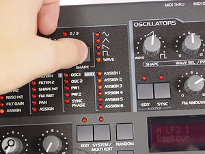
 The most interesting LFO effects available on the Virus are to be found by selecting the Wave option, which gives the LFO access to all the main digital oscillator waveforms. You can then use the MIDI sync functions in the LFO section’s Edit menu to create useful tempo-based rhythmic effects.These more complex waveforms work particularly well when you combine them with MIDI sync. By default LFO timings are absolute, but if you change the Clock setting, within the LFO Edit menu, you’ll see a range of MIDI clock dividers, from tiny fractions of a beat to 16 bars (shown as ’16/1′). The wide range is there to accommodate some of the more frenetic modulation shapes. With a little thought it’s easy to create very complex but stable rhythmic effects by locking both LFOs to MIDI clock, setting each one to a different subdivider and waveshape, and then routing them to Wave Sel, filter cutoff frequencies, the levels of each oscillator, the pitch of oscillator two when the Sync button is turned on, and so on. But how to make these connections? The selection of default assignments available from the panel is more than a touch random. Oscillator pitch is obvious enough, but LFO control of filter resonance isn’t quite so useful and, as we’ve seen, control of oscillator Shape is less useful still. Fortunately, the Assign option provides a much wider range of destinations for both LFOs.
Clicking the button repeatedly steps down the list of destinations on the panel. When the Assign LED turns on, ‘Dest’ appears in the edit window. Now you get a huge range of destinations to choose from, including almost all the programming parameters the Virus has to offer. Aside from conventional patching possibilities (pitch, filter cutoff, and so on) there are also more adventurous destinations, such as the envelope timing parameters and arpeggiator controls. You can also modulate effects settings, such as delay time and reverb mix. You can even make the LFOs modulate each other, for chaotic and unpredictable effects.
When you combine complex waveforms with MIDI sync and this very rich selection of modulation routings, you can add another level of movement to rhythmic patches, or create very fluid and interesting slowly evolving pads and abstract tones. The patching possibilities rival those of a medium-sized modular, but with the advantages of MIDI sync, polyphony, and patch memories. It’s perhaps best to explore these combinations without too much direction from a feature like this one. The basic principle of using unusual LFO waveforms with MIDI sync and perhaps the arpeggiator gives you plenty of scope for colourful sound creation. As with a real analogue synth, exploring the possibilities makes finding some trademark programming effects and a signature sound more likely.
Virus Tips
- In the Ctrl menus you’ll find Random Para Depth and Amount settings. Depth sets the number of parameters that are randomised, and Amount sets the scale of the changes. A large Depth will change effects parameters as well as patch basics. This section is incredibly useful for creating sounds and patches you wouldn’t invent on your own.
- You can control the arpeggiator pattern number with an LFO or other modulation source. This might not seem hugely useful, but it’s a good way to create a rhythmic riff that’s always changing. With careful fine-tuning this can be a surprisingly sophisticated effect.
- The latest OS updates include some fancy delay modes in the delay/reverb section. The delay time can be locked to MIDI Clock, and these modes produce different multiples of a sub-beat for left and right channels. For instance, ‘1+4’ means 1/16 of a beat at the left and 4/16 at the right). When combined with the arpeggiator, these sound truly wonderful.
 You can download this free version of Sound Diver for the Virus synths from the main Access web site.
 - Older versions of the Virus took a rather random approach to sync’ing using MIDI Clock. The arpeggiator would start when you hit a key, which could sometimes be some way off the beat. On the Virus B, OS v4.07 (and higher variants on other models) solves this problem by estimating beats from MIDI Clock start. This makes live arpeggiator performance considerably easier, but also loses some of the feel you could introduce by deliberately playing ahead or behind the beat. If you prefer the original random approach, you can find older versions of the OS archived on the Access web site.
- Although the Virus lacks an ‘analogue detune’ parameter, you can simulate it by setting the first LFO to Wave and using the modulation matrix to patch a small amount to each of the oscillators. This creates the classic analogue ‘not quite in tune’ effect. Make sure the LFOs are working polyphonically, otherwise you’ll get a patch where the pitch wobbles are alarmingly in unison.
- A feature in the newer models and OS updates lets you write your favourite patches to the ROM banks. In the System menu, find Store To Flash, select which banks you want to copy, and then wait while the internal flash programmer rewrites the flash ROM. You can only save entire banks, so its best to get your patches organised first using the Sound Diver utility before attempting a burn.

Arpeggiator Tricks
And what about that arpeggiator? By default it has the usual selection of modes: up, down, random, and so on. These aren’t very exciting, but using the Pattern parameter brings in a range of rhythmic repeats that spice up the sound and make it much more interesting. There are 64 of these (if you have an older OS you’ll find fewer available — you can get the rest by upgrading) and they use the same clock divider system as the LFOs, so it’s easy to create MIDI sync. At very fast subdivisions, such as 1/64, you can create whirring distorted effects.
 If you switch the Arpeggiator to its fastest Clock setting, you can generate whirring, buzzing distortions.The arpeggiator also hides a secret, which is that notes in each pattern include velocity information. So patching velocity to filter cutoff, Wave Sel, or some other timbral parameter can produce some wonderfully dynamic rhythmic effects. As a good rule of thumb, most patches with a fast attack sound good when arpeggiated this way, and it’s worth spending a productive hour or two trying out arpeggiation on all the presets that don’t have it already. The top 30 patterns or so include twiddles, legato glides, and burrs designed to add interest to dance music. Many of these sound best in one of the Mono modes, and turning manually-controlled portamento on can create some very TB303-like acid effects.
Using the arpeggiator in Multi mode can easily create monstrous arpeggios of ultimate doom! The trick here is to try to use patches and pitches that are distinct enough to be heard clearly. You can also add basic rhythm by filling out the sound with arpeggiated bass drum, snare, and hi-hat patches — the latter especially can benefit from some of the more intricate patterns that are available.
Effects & Processing
The effects section of the Virus is an understated beast. Each voice in the Virus C has its own completely independent effects chain, with phaser, chorus, delay/reverb, and three-band EQ. Although you can use these effects just for adding gloss to your synth sounds, it’s more interesting to include them within patches in a more organic way. The key here is the modulation section buried deep inside the main Edit menu. This works like the LFO assignment section, but is independent of it and offers a much wider range of sources, including various MIDI controllers, velocity, and also the envelope outputs. The destinations include most of the parameters inside the Virus — including many effects control parameters.
This means, for example, that you can use an envelope or one of the continuous controller channels to control delay time or phaser frequency. A good start is to experiment with adjusting the effects using the synth section’s modulation sources. Doing this will give you a whole new palette of sounds and effects you probably never expected to hear from a synth.
And finally, there’s external processing to think about. Access have made it easy to assign external inputs to oscillator control for FM, to the ring modulator, and of course to the filters. The big attraction in the last case is that this will also route audio through the effects section, so you can use filtering and level control at the same time as adding delay effects and chorus — ideal for chopped up dance pads, for example.
But perhaps the most impressive effect which uses the external inputs is the vocoder. The manual does a good job of explaining how this works, and if reading about it doesn’t make it clear, practice soon will. What’s not so obvious is that the vocoder parameters can be programmed and sequenced via MIDI using the standard Virus panel assignments. This gives you total control over spread, bank offset, resonance, and all the other ingredients of the vocoder sound, and setting up rhythmic MIDI control can create some extremely dynamic and unusual effects. If you have a MIDI processor like Cycling 74 Max/MSP or Emagic Logic, you can even route the output from the arpeggiator to these parameters in real time.
Super Bug!
It’s likely that many Virus owners aren’t using their synths to maximum effect. However, unlike other synths where intensive patch programming produces sounds that are more gimmicky than interesting, the Virus is an extremely musical product and will enthusiastically repay an adventurous approach.
Sound Files
If you’d like to hear how the programming techniques in this article work, then audition the following six audio files (in the righthand sidebar of this article):
- wavesel.mp3. This shows how you can create timbral changes by routing the velocity values of incoming MIDI note messages to the Wave Sel control.
- lfopad.mp3. Here LFOs modulate pulse width and also fade the different oscillators in and out, thus creating movement in the pad sound.
- fmblips.mp3. The stepped transients that you get in FM mode by detuning the oscillators as low as possible can tease a variety of textures out of the filter section when its resonance settings are up high.
- vocalfx.mp3. If you set the filters up carefully, it’s possible to get vocal formant effects which can be controlled by MIDI note velocities.
- lfoarp.mp3. Combining the effects of some of the Virus’s more complex LFO waveforms with those of the arpeggiator, you can create rhythmic chordal patterns which evolve over long periods.
- vocoder.mp3. Here a synth line has been fed through the vocoder while the vocoder’s parameters are modulated over MIDI.