Hide thumbs
Also See for ADAM-6000 series:
- Manual (6 pages)
-
Bookmarks
Quick Links
Ethernet-based Data Acquisition and Control Modules
User’s Manual
Select Your Hardware Component
Hardware Installation Guide
I/O Module introduction
System Configuration Guide
Evolved for the eWorld
Plan Your Application Program
Related Manuals for Advantech ADAM-6000 series
Summary of Contents for Advantech ADAM-6000 series
-
Page 1
Ethernet-based Data Acquisition and Control Modules User’s Manual Select Your Hardware Component Hardware Installation Guide I/O Module introduction System Configuration Guide Evolved for the eWorld Plan Your Application Program… -
Page 2
No part of this manual may be reproduced, copied, translated or transmitted in any form or by any means without the prior written permission of Advantech Co., Ltd. Information provided in this manual is intended to be accurate and reliable. -
Page 3
Because of Advantech’s high quality-control standards and rigorous testing, most of our customers never need to use our repair service. If an Advantech product ever does prove defective, it will be repaired or replaced at no charge during the warranty period. -
Page 4
Our dealers are well trained and ready to give you the support you need to get the most from your Advantech products. In fact, most problems reported are minor and are able to be easily solved over the phone. -
Page 5
Manual Organization This Manual has six chapters, three appendices. The following table lists each chapter or appendices with its corresponding title and a brief overview of the topics covered in it. Chapter / Title Topics Covered Appendix Introduces the suitable applying industries and the position in an Ethernet remote system. -
Page 6
How to use this manual The following flow chart demonstrates a thought process that you can use when you plan your ADAM-6000 Ethernet Data Acquisition and Control System. -
Page 7
Chapter 1 Understanding Your System Using this Chapter If you want to read about Go to page Introduction Major Feature Technical Specification LED Status of ADAM-6000 I/O Modules… -
Page 8
Through de-factor standard Ethernet networking, ADAM-6000 retrieves I/O values from sensors and publishes these real-time I/O value to networking nodes at local area network or Intranet, Internet. With Ethernet-enabled technology, ADAM-6000 series modules build up a cost-effective DA&C system for Building Automation, environmental monitoring, facility management and eManufacturing applications. -
Page 9
1-2 Major Features 1-2-1 Ethernet-enabled DA&C I/O Modules ADAM-6000 is based on the popular Ethernet networking standards used today in most business environments. Users can easily add ADAM-6000 I/O modules to existing Ethernet networks or use ADAM-6000 modules in new Ethernet-enabled eManufacturing networks. ADAM-6000 module features a 10/100 Mbps Ethernet chip and supports industrial popular Modus/TCP protocol over TCP/IP for data connection. -
Page 10
Based on the Modbus/TCP standard, the ADAM-6000 firmware is a built-in Modbus/TCP server. Therefore, Advantech provides the necessary DLL drivers, OPC Server, and Windows Utility for users for client data for the ADAM-6000P. Users can configure this DA&C system via Windows Utility;… -
Page 11
1-3 Common technical specification of ADAM-6000 • Ethernet: 10 BASE-T IEEE 802.3 100 BASE-TX IEEE 802.3u • Wiring: UTP, category 5 or greater • Bus Connection: RJ45 modular jack • Comm. Protocol: Modbus/TCP on TCP/IP and UDP • Data Transfer Rate: Up to 100 Mbps •… -
Page 12
1-4 Dimensions The following diagrams show the dimensions of the ADAM-6000 l/O module in millimeters. Figure 1-2: ADAM-6000 Module Dimension… -
Page 13
1-5 LED Status of ADAM-6000 I/O Modules There are two LEDs on the ADAM-6000 I/O Modules front panel. Each LEDs built with two indicators to represent the ADAM-6000 system status, as explained below: Figure 1-3: ADAM-6000 I/O Modules’ LED Indicators (1) Status: Red indicator. -
Page 14
Chapter 2 Selecting Your Hardware Components Using this Chapter If you want to read about Go to page Selecting I/O Module Selecting Link Terminal & Cable (Ethernet) Selecting Operator Interface… -
Page 15
2-1 Selecting I/O Module To organize an ADAM-6000 remote data acquisition & control system, you need to select I/O modules to interface the host PC with field devices or processes that you have previously determined. There are several things should be considered when you select the I/O modules. -
Page 16
2-2 Selecting Link Terminal and Cable Use the RJ-45 connector to connect the Ethernet port of the ADAM-6000 to the Hub. The cable for connection should be Category 3 (for 10Mbps data rate) or Category 5 (for 100Mbps data rate) UTP/STP cable, which is compliant with EIA/TIA 586 specifications. -
Page 17
Intellution Fix of i-Fix Any other software support Modbus/TCP protocol Moreover, Advantech also provides OPC Server, the most easy-to-use data exchange tool in worldwide. Any HMI software designed with OPC Client would be able to access ADAM-6000 I/O modules. Modbus/TCP OPC Server If you want to develop your own application, the DLL driver and ActiveX will be the best tools to build up user’s operator interface. -
Page 18
Chapter 3 Hardware Installation Guide Using this Chapter If you want to read about Go to page Determining the proper environment Module Mounting Wiring and Connection… -
Page 19
3-1 Determining the proper environment Before you start to install the ADAM-6000 modules, there are something needed to check. 3-1-1 Check the content of shipping box Unpack the shipping boxes and make sure that the contents include: ADAM-6000 module with one bracket and DIN Rail adapter ADAM-6000 module User’s Notes 3-1-2 System Requirements Host computer… -
Page 20
3-2 Mounting The ADAM-6000 modules designed with compact size and allowed to install in the field site as following methods. 3-2-1 Panel mounting Each ADAM-6000 Module has packed with a plastic panel mounting bracket. Users can refer the dimension of the bracket to configure an optimal placement in the panel or cabinet. Fix the bracket first, then, fix the ADAM-6000 module on the bracket. -
Page 21
Figure 3-2: Fix ADAM-6000 module on the bracket… -
Page 22
3-2-2 DIN rail mounting The ADAM-6000 module can also be secured to the cabinet by using mounting rails. Fix the ADAM-6000 module with the DIN Rail adapter as figure 3-3. Then secured it on the DIN rail as figure 3-4. If you mount the module on a rail, you should also consider using end brackets at each end of the rail. -
Page 24
Figure 3-4: Secure ADAM-6000 Module to a DIN rail… -
Page 25
3-3 Wiring and Connections This section provides basic information on wiring the power supply, I/O units, and network connection. 3-3-1 Power supply wiring Although the ADAM-6000/TCP systems are designed for a standard industrial unregulated 24 V DC power supply, they accept any power unit that supplies within the range of +10 to +30 V . -
Page 26
3-3-2 I/O modules wiring The system uses a plug-in screw terminal block for the interface between I/O modules and field devices. The following information must be considered when connecting electrical devices to I/O modules. 1. The terminal block accepts wires from 0.5 mm to 2.5 mm. 2. -
Page 27
Figure 3-6: ADAM-6000 I/O Module Terminal Block wiring… -
Page 28
Chapter 4 I/O Module Introduction Using this Chapter If you want to read about Go to page Analog Input Module Digital Input / Output Module… -
Page 29
4-1 Analog Input Module Analog input modules use an A/D converter to convert sensor voltage, current, thermocouple or RTD signals into digital data. The digital data is then translated into engineering units. When prompted by the host computer, the data is sent through a standard 10/100 based-T Ethernet interface. Users would able to read the current status via pre-built web page or any HMI software package supported Modbus/TCP protocol. -
Page 30
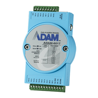
ADAM-6017 Specification Analog Input • Effective resolution: 16-bit • Channels: 8 differential • lnput type: mV, V, mA • lnput range: ±150 mV, ±500 mV, ±1 V, ±5 V, ±10 V, 0-20 mA, 4-20 mA • Isolation voltage: 3000 V •… -
Page 31
Application Wiring Figure 4-2: ADAM-6017 millivoltage, voltage, and current Input Wiring ADAM-6017 has built with a 120 ohms resistor in each channel, users do not have to add any resistors in addition for current input measurement. Just adjust the jumper setting to choose the specific input type you need. -
Page 32
Figure 4-4: ADAM-6017 Digital Output wiring… -
Page 33
Assigning address for ADAM-6017 Modules Basing on Modbus/TCP standard, the addresses of the I/O channels in ADAM-6000 modules you place in the system are defined by a simple rule. Please refer the Figures 4-5 to map the I/O address. Figure 4-5: ADAM-6017 I/O Address Mapping… -
Page 34
4-2 Digital I/O Module ADAM-6050 18-channel Digital I/O Module The ADAM-6050 is a high-density I/O module built-in a 10/100 based-T interface for seamless Ethernet connectivity. It provides 12 digital input and 6 digital output channels with 5000V Isolating protection. All of the Digital Input channels support input latch function for important signal handling. Mean while, these DI channels allow to be used as 1 KHz counter. -
Page 35
ADAM-6050 Specification Analog Input • Channel: 18 • I/O type: 12 DI & 6 DO • Digital Input: Dry Contact: Logic level 0: Close to GND Logic level 1: Open (Logic level status can be inversed by Utility) • Digital Output: Open Collector to 30 V 200 mA max. -
Page 36
Figure 4-8: ADAM-6050 Digital Output Wiring… -
Page 37
Assigning address for ADAM-6050 Modules Basing on Modbus/TCP standard, the addresses of the I/O channels in ADAM-6000 modules you place in the system are defined by a simple rule. Please refer the Figures 4-10 to map the I/O address. Figure 4-9 ADAM-6050 I/O Address Mapping… -
Page 38
All Digital Input channels in ADAM-6050 are allowed to use as 32-bit counters (Each counter is consisted of two addresses, Low word and High word). Users could configure the specific DI channels to be counters via Windows Utility. The I/O address will be mapped as Figures 4-10. Figure 4-10 ADAM-6050 Counter Address Mapping… -
Page 39
ADAM-6051 16-channel Digital I/O w/Counter Module The ADAM-6051 is a high-density I/O module built-in a 10/100 based-T interface for seamless Ethernet connectivity. It provides 12 digital input, 2 digital output, and 2 counter (10 KHz) channels with 5000V Isolating protection. All of the Digital Input channels support input latch function for important signal handling. -
Page 40
ADAM-6051 Specification • Channel: 16 • I/O type: 12DI / 2DO / 2Counter • Digital Input: Dry Contact: Logic level 0: Close to GND Logic level 1: Open (Logic level status can be inversed by Utility) • Digital Output: Open Collector to 30 V 200 mA max. -
Page 41
Figure 4-13: ADAM-6051 Digital Output and Counter Wiring… -
Page 42
Assigning address for ADAM-6051 Modules Basing on Modbus/TCP standard, the addresses of the I/O channels in ADAM-6000 modules you place in the system are defined by a simple rule. Please refer the Figures 4-14 to map the I/O address. Figure 4-14: ADAM-6051 I/O Address Mapping… -
Page 43
All Digital Input channels in ADAM-6051 are allowed to use as 32-bit counters (Each counter is consisted of two addresses, Low word and High word). Users could configure the specific DI channels to be counters via Windows Utility. The I/O address will be mapped as Figures 4-15. Figure 4-15: ADAM-6051 Counter Address Mapping… -
Page 44
ADAM-6060 6-channel Relay Output with DI Module The ADAM-6060 is a high-density I/O module built-in a 10/100 based-T interface for seamless Ethernet connectivity. Bonding with an Ethernet port and web page, the ADAM-6060 offers 6 relay (form A) output and 6 digital input channels. It supports contact rating as AC 120V @ 0.5A, and DC 30V @ 1A. All of the Digital Input channels support input latch function for important signal handling. -
Page 45
ADAM-6060 Specification • Channel: 12 • I/O type: 6 Relay & 6 DI • Relay Output (Form A): Contact rating: AC: 120 V @ 0.5 A DC: 30 V @ 1 A Breakdown voltage: 500 V (50/60 Hz) Relay on time: 7 msec; Relay off time: 3 msec. Total switching time: 10 msec. -
Page 46
Figure 4-18: ADAM-6060 Relay Output Wiring… -
Page 47
Assigning address for ADAM-6060 Modules Basing on Modbus/TCP standard, the addresses of the I/O channels in ADAM-6000 modules you place in the system are defined by a simple rule. Please refer the Figures 4-19 to map the I/O address. Figure 4-19: ADAM-6060 I/O Address Mapping… -
Page 48
All Digital Input channels in ADAM-6060 are allowed to use as 32-bit counters (Each counter is consisted of two addresses, Low word and High word). Users could configure the specific DI channels to be counters via Windows Utility. The I/O address will be mapped as Figures 4-20. Figure 4-20: ADAM-6060 Counter Address Mapping… -
Page 49
Chapter 5 System Configuration Guide Using this Chapter If you want to read about Go to page System Hardware Configuration Install Utility Software I/O Module Configuration 5-10 I/O Module Calibration 5-17 Security Setting 5-18 Technical Emulation 5-19… -
Page 50
This chapter explains how to use ADAM Ethernet I/O Utility to configure the ADAM-6000 modules for various applications. Users can learn the hardware connection, software installation, communication setting and every procedure for system configuration from these sections. 5-1 System Hardware Configuration As we mentioned in chapter 3-1, you will need following items to complete your system hardware configuration. -
Page 51
5-2 Install Utility Software on Host PC Advantech provide free download Manual and Utility software for ADAM-6000 modules’ operation and configuration. Link to the web site: www.advantech.com and click into the “Download Area” under Service & Support site to get the latest version ADAM-6000 manual and Ethernet I/O Utility. -
Page 52
5-3-1 Main Menu Double Click the icon of ADAM Ethernet I/O Utility shortcut, the Operation screen will pop up as Figure 5-2. Figure 5-2 Operation Screen The top of the operation screen consists of a function menu and a tool bar for user’s commonly operating functions. -
Page 53
Terminal Call up the operation screen of Terminal emulation to do the request / response command execution. Item contents Timeout and Scan Rate setting functions. Please be aware of the time setting for Setup other Ethernet domination usually longer than local network. Item contents on-line help function as user’s operation guide;… -
Page 54
5-3-2 Network Setting As the moment you start up this Windows Utility, it will search all ADAM-6000 I/O modules and ADAM-5000/TCP on the host PC’s domination Ethernet network automatically. Then the tree-structure display area will appeal with the searched units and the relative IP address. Figure 5-4 Network Setting… -
Page 55
See Figure 5-4, there are also Host PC’s information in the status display area, include host name and IP address. Moreover, the Windows Utility provides network connection test tool for user to verify whether the communication is workable. Key-in the specific IP address you want to connect and click button, the testing result will show as Figure 5-5. -
Page 56
Click the Network Tab to configure the TCP/IP network setting Step2. Figure 5-7 TCP/IP Network setting MAC Address This is also called Ethernet address and needs no further configuration. Link Speed This function will show the current linking speed to be either 10Mbps or 100Mbps. However, the utility will auto-detect the current transmission speed on the network segment and set the transmission speed for the device accordingly without your further efforts. -
Page 57
5-3-3 Add Remote Stations To meet the remote monitoring and maintenance requirements, The ADAM-6000 and ADAM-5000/TCP System does not only available to operate in local LAN, but also allowed to access from Internet or Intranet. Thus users would able to configure an ADAM-6000 and ADAM-5000/TCP easily no matter how far it is. -
Page 58
5-3-4 I/O Module Configurations Digital Input Output Module Selecting ADAM-6000 Digital Modules includes ADAM-6050/605/6060, user can read following information from the Utility. Figure 5-9 Digital I/O Module Configuration Location Standard Modbus address. ADAM Ethernet I/O Utility shows the Modbus mapping address of each I/O channel. -
Page 59
In addition to monitor the current DI/DO status, the Windows Utility offers a graphical operating interface as figure 5-10. You can read the Digital input status through the change of the indicator icons. Oppositely, you can write the digital output status through clicking the indicator icons. Figure 5-10 Operating and Indicating Icons Note 1 The indicator icons are only available to click for digital output channel. -
Page 60
Figure 5-12 Counter Input Mode Figure 5-13 Latch Input Mode Note: The new working mode setting will take effective after click the “Update” button. If necessary, users could invert the original single for flexible operation needs. -
Page 61
The digital output channels support pulse output and delay output functions. Click the specific channel, there will be four working modes for choosing. Figure 5-14 Pulse Output Mode Setting Figure 5-15 Delay Output Mode Setting… -
Page 62
Analog Input Module Selecting ADAM-6000 Analog Input Modules includes ADAM-6017, users can read following information from the Utility. Figure 5-16 Current Analog Input Status Location Standard Modbus address. (Refer to Assigning address for I/O module in Chapter 4) Type Data type of the I/O channel. The data type of analog Input modules is always “word”. Value The current status on each channel of I/O modules. -
Page 63
To provide users more valuable information, the ADAM-6000 analog modules have designed with calculation functions, includes Maximum, Minimum, and Average values of individual channels. Click the Maximum value tab, you will see the historical maximum values in each channel unless to press the against “Reset”… -
Page 64
Moreover, all of the analog channels are allowed to configure the High/Low limitation for alarm trigger function. Once the value of the specific channel over or under the limitation, the alarm status could trigger a digital output channel in the ADM-6017. Figure 5-20 Alarm Setting… -
Page 65
5-3-5 I/O Module Calibrations Calibration is to adjust the accuracy of ADAM module. There are several modes for module’s calibration: Zero calibration, Span calibration, CJC calibration, and Analog Output calibration. Only analog input and output modules can be calibrated, and the ADAM-6017 is the first released analog module. Zero Calibration 1. -
Page 66
(Network, Firmware, Password) are only allowed to be changed by password verification. Figure 5-23 Password Setting Note: The default password of ADAM-6000 is “00000000”. Please make sure to keep the correct password by yourself. If you lose it, please contact to Advantech’s technical support center for help. -
Page 67
5-3-7 Terminal Emulations You can issue commands and receive response by clicking the Terminal button on the tool bar. There are two kinds of command format supported by this emulating function. Users can choose ASCII or Hexadecimal mode as their communication base. If the ASCII mode has been selected, the Windows Utility will translate the request and response string both in Modbus and ASCII format. -
Page 68
5-3-8 Data Stream Data Stream Configuration In addition to TCP/IP communication protocol, ADAM-6000 supports UDP communication protocol to regularly broadcast data to specific host PCs. Click the tab of Data Stream, then configure the broadcasting interval and the specific IP addresses which need to receive data from the specific ADAM-6000 I/O module. -
Page 69
Data Stream Monitoring After finishing the configuration of Data Stream, you can select the item “Monitor Data Stream” in the function bar or click icon to call up operation display as Figure 5-26. Figure 5-26 Data Stream Monitoring Select the IP address of the ADAM-6000 you want to read data, then click “Start ” button. The Utility software will begin to receive the stream data on this operation display. -
Page 70
5-3-9 Firmware and Web Page Update ADAM-6000 I/O modules are available to remote download firmware for customization web pages or new functions upgrade. Select the Firmware Upgrade tab and click the “Browsing” button to find the specific firmware (*.bin) for upgrade. Figure 5-27 Firmware Upgrade Click the upgrade button, then the new firmware will be downloaded into the specific ADAM-6000 module. -
Page 71
Instructions to Java Applet Customization Introduction In this section, we will tell you the way to create an applet web page to monitor the status of ADAM-6060 through the Web browser. To write an input processing applet, you need to know how to define a class with multiple methods. -
Page 72
Employing these four methods, you can customize your applet and focus solely on the user interface you intend to create and the number of channels you want to monitor. An Example To process ADAM-6060 input and display the result/status on an applet, we will use objects from the standard java class library and the class we develop. -
Page 73
Firstly, the HTML file must be named “index.html.” The name of parameter in <APPLET…> cannot change. The lines “CODE = «Adam6060.class»” and “ARCHIVE = «Adam6060.jar»” indicate where the class and jar files (your Java Applet program) are for ADAM-6060 module. WIDTH and HEIGHT are parameters to set the visible screen size of your Java Applet Web page. -
Page 74
The fragment is used to obtain the host IP value and check if it is null. To acquire the necessary parameter information from the index.html, you need to add the fragment below. public String[][] getParameterInfo() { String[][] pinfo = {«HostIP», «String», «»}, return pinfo;… -
Page 75
Figure 5-29 Firmware Upgrade for ADAM-6000 I/O Series Modules… -
Page 76
Appendix A Source Code of Java Applet Example import Adam.ModBus.*; import java.awt.*; import java.awt.event.*; import java.applet.*; import java.io.*; import java.lang.*; public class Adam6060 extends Applet { boolean isStandalone = false; String var0; Thread AdamPoilThread; String HostIP; long ErrCnt = 0; boolean IsAdamRuning = false;… -
Page 77
(getParameter(key) != null ? getParameter(key) : def); /**Constructor*/ public Adam6060() { /**Applet Initialization*/ public void init() { try { HostIP = getParameter(«HostIP»); Adam6060Connection = new ModBus(HostIP); //create ADAM-6060 module object if (HostIP == «») //check the Host IP labAdamStatusForDIO.setText(«Get Host IP is null !!»); else labAdamStatusForDIO.setText(«Get Host… -
Page 78
33)); palStatus.setLayout(null); pal1.setLayout(null); pal1.add(labStartAddress, null); pal1.add(txtStartAddress, null); pal1.add(labCount, null); pal1.add(txtCount, null); pal1.add(btAdam6060, null); labStartAddress.setBounds(new Rectangle(20, 15, 85, 20)); txtStartAddress.setBounds(new Rectangle(205, 15, 60, 20)); labCount.setBounds(new Rectangle(20, 40, 180, 20)); txtCount.setBounds(new Rectangle(205, 40, 60, 20)); btAdam6060.setBounds(new Rectangle(275, 40, 80, 22)); btAdam6060.addMouseListener(new java.awt.event.MouseAdapter() { public void mousePressed(MouseEvent e) { //mouse event handling int i, j;… -
Page 79
Adam6060Connection = new ModBus(HostIP); catch(Exception eNet) { eNet.printStackTrace(); } palAdamStatus.setLayout(null); pal2.setLayout(null); pal2.add(txtMsg, null); txtMsg.setBounds(new Rectangle(15, 15, 355, 120)); Label1.setFont(new java.awt.Font(«DialogInput», 3, 26)); Label1.setForeground(Color.blue); Label1.setText(«ADAM-6060 DIO Module»); Label1.setBounds(new Rectangle(83, 17, 326, 29)); this.add(Label1, null); this.add(palStatus, null); palStatus.add(pal1, null); palStatus.add(pal2, null); palStatus.add(palAdamStatus, null); labAdamStatusForDIO.setBounds(new Rectangle(10, 8, 350, 12));… -
Page 80
/**Main method: for the purpose of laying out the screen in local PC*/ public static void main(String[] args) { Adam6060 applet = new Adam6060(); applet.isStandalone = true; Frame frame; frame = new Frame() { protected void processWindowEvent(WindowEvent e) { super.processWindowEvent(e); if (e.getID() == WindowEvent.WINDOW_CLOSING) { System.exit(0);… -
Page 81
Label labMassage = new Label(«»); public myFramPanel() { //super(); public myFramPanel(int myType) { //super(); panelType = myType; public myFramPanel(int myType, String Msg, int msgTextLength) { //super(); panelType = myType; if (Msg != «») { labMassage.setText(Msg); this.setLayout(null); labMassage.setBounds(new Rectangle(20, 3, msgTextLength, 15));… -
Page 82
g.setColor(Color.black); g.drawRect(off, off, size.width — 2 — off * 2, size.height — 2 — off * 2); else if (panelType == 2) g.setColor(Color.white); g.drawRect(0, 0, size.width — 1, size.height — 1); g.drawLine(size.width — 4, 2, size.width — 4, size.height — g.drawLine(2, size.height — 4, size.width — 4, size.height — 4);… -
Page 83
— 2 — off * 2 -5 ); else { g.setColor(Color.darkGray); g.drawRect(0, 0, size.width — 1, size.height — 1); Snapshot of the Running Applet… -
Page 84: Table Of Contents
Chapter 6 Planning Your Application Program Using this Chapter If you want to read about Go to page DLL Driver Command Structure 6-23 Modbus Function Code Introduction 6-24 Apply with ASCII Command 6-29 — System Command Set 6-35 — Analog Input Command Set 6-39 — Analog Input Alarm Command Set 6-56…
-
Page 85
6-1 Introduction After completing the system configuration, you can begin to plan the application program. This chapter introduces two programming tools for users to execute system data acquisition and control. The DLL drivers and command sets provide a friendly interface between your applications and ADAM-6000 I/O modules. -
Page 86
There are eight function libraries common used by ADAM-6000 and ADAM-5000/TCP list as follow: ADAMTCP_Connect ADAMTCP_Disconnection ADAMTCP_GetDLLVersion ADAMTCP_ReadReg ADAMTCP_WriteReg ADAMTCP_ReadCoil ADAMTCP_WriteCoil ADAMTCP_SendReceive5KTCPCmd In addition, Advantech offers more function libraries especially for various ADAM-6000 applications. ADAMTCP_SendReceive6KTCPCmd ADAMTCP_Read6KDIO ADAMTCP_Write6KDO ADAMTCP_Read6KAI ADAMTCP_Read6KDIOMode ADAMTCP_Write6KDIOMode ADAMTCP_Read6KSignalWidth ADAMTCP_Write6KsignalWidth… -
Page 87
6-2-2 Function Descriptions ADAMTCP_Connect Description: Establish a Windows Sockets connection in a specified ADAM-6000 I/O module. Syntax: int ADAMTCP_Connect(int socket_type, char *szIP, unsigned short port, SOCKET *conn_socket, int iConnectionTimeout, int iSendTimeout, int iReceiveTimeout); Parameter: socket_type[in]: to specify the connection type that is UDP or TCP. szIP[in]: the IP address for ADAM-6000 that to be connected. -
Page 88: Dll Driver
ADAMTCP_Disconnect Description: Disconnect the Windows Sockets connection of the specified ADAM-6000 I/O module. Syntax: void ADAMTCP_Disconnect(void); Parameter: void Return: Please refer to Chapter 6-2-3 “Return Codes” for more detail information ADAMTCP_GetDLLVersion Description: Read the version of ADAM-6000 DLL driver Syntax: int ADAMTCP_GetDLLVersion(void);…
-
Page 89
ADAMTCP_ReadReg Description: Read the holding register value at a specified range described in parameters. Syntax: int ADAMTCP_ReadReg(SOCKET conn_socket, WORD wStartAddress, WORD wCount, WORD wData[ ]) Parameter: conn_socket[in]: the handle that represent the connection socket wStartAddress[in]: the starting address that to be read wCount[in]: how many holdings register to be read wData[out]:… -
Page 90
//——— default timeout —— iConnectionTimeout=2000; iSendTimeout=2000; iReceiveTimeout=2000; int main(int argc, char **argv) i,j; SOCKET conn_socket; iRetVal,iVersion; WORD wStartAddress=1; WORD wCount=16; WORD wData[16]; char line[80]; printf(«In this demo, the IP Address of 6000 module is assumed as 172.16.2.200n»); printf(«Please make sure the IP Address for your 6000 module is 172.16.2.200 (Y/N)? «); gets(line);… -
Page 91
//— reading input register — iRetVal=ADAMTCP_ReadReg(conn_socket, wStartAddress, wCount,wData); if( iRetVal ) printf(«ADAMTCP_ReadReg() Fail !!! code=%dn»,iRetVal); ADAMTCP_Disconnect(); exit(0); for(i=0,j=wStartAddress; i<wCount; i++,j++) printf(«Addr:[%d] -> %04xn»,j,wData[i]); printf(«n»); //— Lastly, disconnection to 6000 I/O Modules — ADAMTCP_Disconnect(); printf(«ADAMTCP_Discennect() successful !n»);… -
Page 92
ADAMTCP_WriteReg Description: Write the holding register value at a specified range described in parameters. Syntax: int ADAMTCP_WriteReg(SOCKET conn_socket, WORD wStartAddress, WORD wCount, WORD wData[ ]) Parameter: conn_socket[in]: the handle that represent the connection socket wStartAddress[in]: the starting address that to be read wCount[in]: how many holdings register to be read wData[out]:… -
Page 93
ADAMTCP_WriteCoil Description: Write the coils value at a specified range described in parameters. Syntax: int ADAMTCP_WriteCoil(SOCKET conn_socket, WORD wStartAddress, WORD wCount, BYTE byData[ ]) Parameter: conn_socket[in]: the handle that represent the connection socket wStartAddress[in]: the starting address that to be read wCount[in]: how many coils to be read byData[out]:… -
Page 94
ADAMTCP_SendReceive6KTCPCmd Description: This function is specific for 6000 series. It accepts the command in ASCII format string. Then transform it to follow the Modbus/TCP communication protocol. Syntax: int ADAMTCP_SendReceive6KTCPCmd(char szIP[], char szSendToTCP[], char szReceiveFromTCP[] char szModbusSend[], char szModbusReceive[]) Parameter: szIP[in]: the IP Address of the target ADAM-6000 module to be connected. -
Page 95
ADAMTCP_Read6KDIO Description: To read the DI/DO status in the specific ADAM-6000 module. Syntax: int ADAMTCP_Read6KDIO(char szIP[], WORD wModule, WORD wIDAddr, BYTE byDI[], BYTE byDO[]) Parameter: szIP[in]: the IP Address of the target ADAM-6000 module to be connected. wModule[in]: the module name of the ADAM-6000 module to be connected. (For example, 6050, 6051, or 6060) wIDAddr[in]: the Modbus device ID for an ADAM-6000 module. -
Page 96
ADAMTCP_Write6KDO Description: Set D/O status to an specific ADAM-6000 module. Syntax: int CALLBACK ADAMTCP_Write6KDO(char szIP[], WORD wModule, WORD wIDAddr, WORD wStartDO, WORD wCount, BYTE byDO[]) Parameter: szIP[in]: the IP Address of the target ADAM-6000 module to be connected. wModule[in]: the module name of the ADAM-6000 module to be connected. (For example, 6050, 6051, or 6060) wIDAddr[in]: the Modbus device ID for an ADAM-6000 module. -
Page 97
ADAMTCP_Read6KAI Description: To read analog input channel’s value for an ADAM-6000 module. Syntax: int ADAMTCP_Read6KAI(char szIP[], WORD wModule, WORD wIDAddr, WORD wGain[], WORD wHex[], double dlValue[]) Parameter: szIP[in]: the IP Address of the target ADAM-6000 module to be connected. wModule[in]: the module name of the ADAM-6000 module to be connected. -
Page 98
ADAMTCP_Read6KDIOMode Description: To read the working mode of each DI/O channels in a specific ADAM-6000 module. Syntax: int ADAMTCP_Read6KDIOMode(char szIP[], WORD wModule, WORD wIDAddr, BYTE byDIMode[], BYTE byDOMode[]) Parameter: szIP[in]: the IP Address of the target ADAM-6000 module to be connected wModule[in]: the module name of the ADAM-6000 module to be connected. -
Page 99
ADAMTCP_Write6KDIOMode Description: To set the working modes for each DI/O channels in a specific ADAM-6000 module. Syntax: int ADAMTCP_Wirte6KDIOMode(char szIP[], WORD wModule, WORD wIDAddr, BYTE byDIMode[], BYTE byDOMode[]) Parameter: szIP[in]: the IP Address of the target ADAM-6000 module to be connected. wModule[in]: the module name of the ADAM-6000 module to be connected. -
Page 100
ADAMTCP_Read6KSignalWidth Description: To read the minimal high/low signal width of each D/I channel in a specific ADAM-6000 module. Syntax: int ADAMTCP_Read6KSignalWidth(char szIP[], WORD wModule, WORD wIDAddr, unsigned long ulLoWidth[], unsigned long ulHiWidth[]) Parameter: szIP[in]: the IP Address of the target ADAM-6000 module to be connected. wModule[in]: the module name of the ADAM-6000 module to be connected. -
Page 101
ADAMTCP_Write6KSignalWidth Description: To set the minimal high/low signal width of each DI channel in a specific ADAM-6000 module. Syntax: int ADAMTCP_Write6KSignalWidth(char szIP[], WORD wModule, WORD wIDAddr, unsigned long ulLoWidth[], unsigned long ulHiWidth[]) Parameter: szIP[in]: the IP Address of the target ADAM-6000 module to be connected. wModule[in]: the module name of the ADAM-6000 module to be connected. -
Page 102
ADAMTCP_Read6KCounter Description: To read the counter value when a DI channel configured in ‘Counter’ mode. Syntax: int ADAMTCP_Read6KCounter(char szIP[], WORD wModule, WORD wIDAddr, unsigned long ulCounterValue[]); Parameter: szIP[in]: the IP Address of the target ADAM-6000 module to be connected. wModule[in]: the module name of the ADAM-6000 module to be connected. -
Page 103
ADAMTCP_Start6KCounter Description: Start counting when a DI channel configured as ‘Counter’ mode. Syntax: int ADAMTCP_Start6KCounter(char szIP[], WORD wAddress, WORD wChIndex) Parameter: szIP[in]: the IP Address of the target ADAM-6000 module to be connected. wIDAddr[in]: the Modbus device ID for an ADAM-6000 module. (Always 1) wChIndex[in]: the specific DI channel need to start or stop counting. -
Page 104
ADAMTCP_Clear6KDILatch Description: To clear the latch when a DI channel configured as ‘Lo to Hi Latch’ or ‘Hi to Lo Latch’. Syntax: int ADAMTCP_Clear6KDILatch(char szIP[], WORD wIDAddr, WORD wChIndex) Parameter: szIP[in]: the IP Address of the target ADAM-6000 module to be connected. wIDAddr[in]: the Modbus device ID for an ADAM-6000 module. -
Page 105
6-2-3 Return Codes Using these function libraries, you can read the error message from the returning codes. ADAM5KTCP_NoError ADAM5KTCP_StartupFailure (-1) ADAM5KTCP_SocketFailure (-2) ADAM5KTCP_UdpSocketFailure (-3) ADAM5KTCP_SetTimeoutFailure (-4) ADAM5KTCP_SendFailure (-5) ADAM5KTCP_ReceiveFailure (-6) ADAM5KTCP_ExceedMaxFailure (-7) ADAM5KTCP_CreateWsaEventFailure (-8) ADAM5KTCP_ReadStreamDataFailure (-9) ADAM5KTCP_InvalidIP (-10) ADAM5KTCP_ThisIPNotConnected (-11) ADAM5KTCP_AlarmInfoEmpty (-12) ADAM5KTCP_NotSupportModule… -
Page 106: Command Structure
6-3 ADAM-6000 Commands ADAM-6000 and ADAM-5000/TCP system accept a command/response form with the host computer. When systems are not transmitting they are in listen mode. The host issues a command to a system with a specified address and waits a certain amount of time for the system to respond. If no response arrives, a time-out aborts the sequence and returns control to the host.
-
Page 107: Modbus Function Code Introduction
And the response should be: Figure 6-2 Response Comment Structure 6-3-2 Modbus Function Code Introductions To full-fill the programming requirement, there is a series of function code standard for user’s reference… Code (Hex) Name Usage Read Coil Status Read Discrete Output Bit Read Input Status Read Discrete Input Bit Read 16-bit register.
-
Page 108
Response message format for function code 01: Command Body Station Function Byte Data Data … Address Code Count Example: Coils number 2 and 7 are on, all others are off. 01 01 01 42 In the response the status of coils 1 to 8 is shown as the byte value 42 hex, equal to 0100 0010 binary. -
Page 109
Response message format for function code 03 or 04: Command Body Station Function Byte Data Data … Address Code Count Example: Analog input #1 and #2 as floating point values where AI#1=100.0 and AI#2=55.32 01 04 08 42 C8 00 00 47 AE 42 5D Function Code 05 Force a single coil to either ON or OFF. -
Page 110
Function Code 08 Echoes received query message. Message can be any length up to half the length of the data buffer minus 8 bytes. Request message format for function code 08: Command Body Station Function Any data, length limited to approximately half the Address Code length of the data buffer… -
Page 111
Function Code 16 (10 hex) Preset values into a sequence of holding registers. Request message format for function code 16: Command Body Station Function Start Address Start Address Requested Number Requested Number Byte Data Address Code High Byte Low Byte of Register High Byte of Register Low Byte Count… -
Page 112: Apply With Ascii Command
6-4 Apply with ASCII Command for ADAM-6000 Modules For users do not familiar to Modbus protocol, Advantech offers a function library as a protocol translator, integrating ASCII command into Modbus/TCP structure. Therefore, users familiar to ASCII command can access ADAM-6000 easily. Before explaining the structure of ASCII command packed with Modbus/TCP format.
-
Page 113
6-4-2 I/O Module Command Set Searching Tables ADAM-6017 Command Table Command Syntax Command Name Description $aaAff Set Integration Time Sets the integration time for a specified module $aaB Get Integration Time Get the integration time from a specified module $aaAnntt Set Input Range Set the input range to the specified channel in the analog input module… -
Page 114
#aaMH Read all Max. Data Read the maximum data from all channels in the specified module #aaMHn Read single Max. Read the maximum date from a Data specified channel in the module #aaML Read all Min. Data Read the minimum data from all channels in the specified module #aaMLn Read single Min. -
Page 115
ADAM-6050 Command Table Command Syntax Command Name Description $aaAff Configuration Sets the integration time for a specified module $aa6 Read Channels Status Asks a specified input module to return the status of all channels #aabb Write Digital Output Writes specified values to either a single channel or all channels simultaneously $aa5… -
Page 116
ADAM-6051 Command Table Command Syntax Command Name Description $aaAff Configuration Sets the integration time for a specified module $aa6 Read Channels Status Asks a specified input module to return the status of all channels #aabb Write Digital Output Writes specified values to either a single channel or all channels simultaneously $aa5… -
Page 117
ADAM-6060 Command Table Command Syntax Command Name Description $aaAff Configuration Sets the integration time for a specified module $aa6 Read Channels Status Asks a specified input module to return the status of all channels #aabb Write Digital Output Writes specified values to either a single channel or all channels simultaneously $aa5… -
Page 118: System Command Set
6-4-3 System Command Set $aaAff Name Set Integration Time Description Sets an integration time to a specified ADAM-6000 module. Syntax $aaAff(cr) $ is a delimiter character. aa (range 00-FF) represents the 2-character hexadecimal Modbus address of the ADAM-6000 module you want to configure. (Always 01) A is I/O module configuration command.
-
Page 119
$aaB Name Read Integration Time Setting Description Read the integration time setting of a specified ADAM-6000 module. Syntax $aaB(cr) $ is a delimiter character. aa (range 00-FF) represents the 2-character hexadecimal Modbus address of the ADAM-6000 module you want to configure. (Always 01) B is I/O module configuration reading command. -
Page 120
$aaM Name Read Module Name Description Returns the module name from a specified ADAM-6000 module. Syntax $aaM(cr) $ is a delimiter character. aa (range 00-FF) represents the 2-character hexadecimal Modbus address of the ADAM-6000 module you want to interrogate. (Always 01) M is the Module Name command. -
Page 121: Analog Input Command Set
$aaF Name Read Firmware Version Description Returns the firmware version code from a specified ADAM-6000 module. Syntax $aaF(cr) $ is a delimiter character. aa (range 00-FF) represents the 2-character hexadecimal Modbus address of the ADAM-6000 module you want to interrogate. (Always 01) F is the Firmware Version command.
-
Page 122
Command Syntax Command Name Description $aaAnntt Set Input Range Set the input range to the specified channel in the analog input module $aaBnn Read Input Range Read the input range of the specified channel in the analog input module #aan Read Analog Input Return the input value from the from Channel N… -
Page 123
Name Set Input Range Description Sets the input range for a specified channel of a specified analog input module. Syntax $aaAnntt $ is a delimiter character. aa (range 00-FF) represents the 2-character hexadecimal Modbus address of the ADAM-6000 module you want to configure. (Always 01) A represents the set input range command. -
Page 124
?aa(cr) if an invalid operation was entered. There is no response if the module detects a syntax error or communication error or if the specified address does not exist. ! delimiter character indicating a valid command was received. ? delimiter character indicating the command was invalid. aa (range 00-FF) represents the 2-character hexadecimal Modbus address of an ADAM-6000 module. -
Page 125
Name Read Input Range Description Returns the input range for a specified channel of a specified analog input module. Syntax $aaBnn $ is a delimiter character. aa (range 00-FF) represents the 2-character hexadecimal Modbus address of the ADAM-6000 module you want to interrogate. (Always 01) B represents the read input range command. -
Page 126
Name Read Analog Input from Channel N Description Returns the input data from a specified channel in a specified analog input module. Syntax $aan $ is a delimiter character. aa (range 00-FF) represents the 2-character hexadecimal Modbus address of the ADAM-6000 module you want to interrogate. (Always 01) n (range 0-8) represents the specific channel you want to read the input data. -
Page 127
Name Read Analog Input from All Channels Description Returns the input data from all channels in a specified analog input module. Syntax $ is a delimiter character. aa (range 00-FF) represents the 2-character hexadecimal Modbus address of the ADAM-6000 module you want to interrogate. (Always 01) (cr) is the terminating character, carriage return (0Dh). -
Page 128
Name Span Calibration Description Calibrates a specified analog input module to correct for gain errors Syntax $aa0(cr) $ is a delimiter character. aa (range 00-FF) represents the 2-character hexadecimal Modbus address of the ADAM-6000 module which is to be calibrated. (Always 01) 0 represents the span calibration command. -
Page 129
Name Zero Calibration Description Calibrates a specified analog input module to correct for offset errors Syntax $aa1(cr) $ is a delimiter character. aa (range 00-FF) represents the 2-character hexadecimal Modbus address of the ADAM-6000 module which is to be calibrated. (Always 01) 1 represents the zero calibration command. -
Page 130
Name Read Channels Status Description Asks a specified input module to return the status of all channels Syntax $aa6(cr) $ is a delimiter character. aa (range 00-FF) represents the 2-character hexadecimal Modbus address of the ADAM-6000 module you want to interrogate. (Always 01) 6 is the read channels status command. -
Page 131
Name Enable/Disable Channels for multiplexing Description Enables/Disables multiplexing for separate channels of the specified input module Syntax $aa5mm(cr) $ is a delimiter character. aa (range 00-FF) represents the 2-character hexadecimal Modbus address of the ADAM-6000 module. (Always 01) 5 identifies the enable/disable channels command. mm (range 00-FF) are two hexadecimal characters. -
Page 132
Name Read Maximum Value Description Read the Maximum values from all channels in a specified analog input module Syntax $aaMH(cr) $ is a delimiter character. aa (range 00-FF) represents the 2-character hexadecimal Modbus address of the ADAM-6000 module to be read. (Always 01) MH represents the read maximum value command. -
Page 133
Name Read Maximum Value from channel N Description Read the Maximum values from a specific channel in a specified analog input module Syntax $aaMHn(cr) $ is a delimiter character. aa (range 00-FF) represents the 2-character hexadecimal Modbus address of the ADAM-6000 module to be read. (Always 01) MH represents the read maximum value command. -
Page 134
Name Read Minimum Value Description Read the Minimum values from all channels in a specified analog input module Syntax $aaML(cr) $ is a delimiter character. aa (range 00-FF) represents the 2-character hexadecimal Modbus address of the ADAM-6000 module to be read. (Always 01) ML represents the read minimum value command. -
Page 135
Name Read Minimum Value from channel N Description Read the Minimum values from a specific channel in a specified analog input module Syntax $aaMLn(cr) $ is a delimiter character. aa (range 00-FF) represents the 2-character hexadecimal Modbus address of the ADAM-6000 module to be read. (Always 01) ML represents the read minimum value command. -
Page 136
Name Enable/Disable Channels for Average Description Enables/Disables the specific channels in the analog input module for the average function. Syntax $aaEmm(cr) $ is a delimiter character. aa (range 00-FF) represents the 2-character hexadecimal Modbus address of the ADAM-6000 module to be read. (Always 01) E represents the enable/disable channel for average command. -
Page 137
Name Read the Average Enable/Disable Status Description Read the average enable/disable status of all channels in the specific analog input module. Syntax $aaE(cr) $ is a delimiter character. aa (range 00-FF) represents the 2-character hexadecimal Modbus address of the ADAM-6000 module to be read. (Always 01) E represents the enable/disable channel for average command. -
Page 138
Name Set Digital Output Description Set the digital output status in ADAM-6000 analog input module. Syntax $aaDnd(cr) $ is a delimiter character. aa (range 00-FF) represents the 2-character hexadecimal Modbus address of the ADAM-6000 module to be read. (Always 01) D represents the digital output setting command. -
Page 139
$aaCjAhs Set Alarm Mode Set the High/Low alarm in either Momentary or Latching mode $aaCjAh Read Alarm Mode Returns the alarm mode for the specified channels $aaCjAhEs Enable/Disable AlarmEnables/Disables the high/low alarm of the specified channels $aaCjCh Clear Latch Alarm Resets a latched alarm $aaCjAhCCn Set Alarm… -
Page 140
Name Set Alarm Mode Description Sets the High/Low alarm of the specified input channel in the addressed ADAM-6000 module to either Latching or Momentary mode. Syntax $aaCjAhs(cr) $ is a delimiter character. aa (range 00-FF) represents the 2-character hexadecimal Modbus network address of an ADAM-6000 module. -
Page 141
Name Read Alarm Mode Description Returns the alarm mode for the specified channel in the specified ADAM-6000 module. Syntax $aaCjAh(cr) $ is a delimiter character. aa (range 00-FF) represents the 2-character hexadecimal Modbus network address of an ADAM-6000 module. (Always 01) Cj identifies the desired channel j (j : 0 to 7). -
Page 142
Name Enable/Disable Alarm Description Enables/Disables the High/Low alarm of the specified input channel in the addressed ADAM-6000 module Syntax $aaCjAhEs(cr) $ is a delimiter character. aa (range 00-FF) represents the 2-character hexadecimal Modbus network address of an (Always 01) ADAM-6000 module. Cj identifies the desired channel j (j : 0 to 7). -
Page 143
Name Clear Latch Alarm Description Sets the High/Low alarm to OFF (no alarm) for the specified input channel in the addressed ADAM-6000 module Syntax $aaCjCh(cr) $ is a delimiter character. aa (range 00-FF) represents the 2-character hexadecimal Modbus network address of an (Always 01) ADAM-6000 module. -
Page 144
Name Set Alarm Connection Description Connects the High/Low alarm of the specified input channel to interlock the specified digital output in the addressed ADAM-6000 module Syntax $aaCjAhCCn(cr) $ is a delimiter character. aa (range 00-FF) represents the 2-character hexadecimal Modbus network address of an (Always 01) ADAM-6000/TCP module. -
Page 145
Name Read Alarm Connection Description Returns the High/Low alarm limit output connection of a specified input channel in the addressed ADAM-6000 module Syntax $aaCjRhC(cr) $ is a delimiter character. aa (range 00-FF) represents the 2-character hexadecimal Modbus address of an (Always 01) ADAM-6000 module. -
Page 146
Name Set Alarm Limit Description Sets the High/Low alarm limit value for the specified input channel of a specified ADAM-6000 module. Syntax $aaCjAhU(data)(cr) $ is a delimiter character. aa (range 00-FF) represents the 2-character hexadecimal Modbus network address of an (Always 01) ADAM-6000 module. -
Page 147
Description Returns the High/Low alarm limit value for the specified input channel in the addressed ADAM-6000 module Syntax $aaCjRhU(cr) $ is a delimiter character. aa (range 00-FF) represents the 2-character hexadecimal Modbus network address of an (Always 01) ADAM-6000 module. Cj identifies the desired analog input channel j (j : 0 to 7). -
Page 148
Syntax $aaCjS(cr) $ is a delimiter character. aa (range 00-FF) represents the 2-character hexadecimal Modbus network address of an (Always 01) ADAM-6000 module. Cj identifies the desired analog input channel j (j : 0 to 7). S is the Read Alarm Status command. (cr) represents terminating character, carriage return (0Dh) Response !aahl(cr) if the command was valid… -
Page 149
#aabb Write Digital Output Writes specified values to either a single channel or all channels simultaneously $aa6 Name Read Channel Status Description This command requests that the specified ADAM-6000 module return the status of its digital input channels and a read-back value of its digital output channels. Syntax $aa6(cr) $ is a delimiter character. -
Page 150
module. The second 2-character portion of the response, value 11h (00010001), indicates that digital input channels 8 and 12 are ‘ON’, channels 9, 10, 11, 13, 14 and 15 are ‘OFF’. The third 2-character portion of the response, value 22h (00100010), indicates that digital input channels 1 and 5 are ON, and channels 0, 2, 3, 4, 6 and 7 are OFF. -
Page 151
Syntax #aabb(data)(cr) # is a delimiter character. aa (range 00-FF) represents the 2-character hexadecimal Modbus network address of the ADAM-6000 module. (Always 01) bb is used to indicate which channel(s) you want to set. Writing to all channels (write a byte): both characters should be equal to zero (BB=00). Writing to a single channel (write a bit): first character is 1, second character indicates channel number which can range from 0h to Fh. -
Page 152
response: >(cr) An output byte with value 12h (00010010) is sent to the digital output module at address 01h. Channels 1and 4 will be set to ‘ON’, and all other channels will be set to ‘OFF’. Note: If any channel of the digital output module is configured as the output for an analog input alarm, it cannot be reconfigured via digital output commands. -
Page 153
Appendix A Design Worksheets… -
Page 154
An organized system configuration will lead to efficient performance and reduce engineer effort. This Appendix provides the necessary worksheet, helping users to configure their DA&C system in order. Follow these working steps to build up your system relational document: Step 1. Asking questions and getting answers for your control strategy. 1) What will be monitored and controlled? (List the equipment) 2) What will be monitored and controlled separately? (Divide the function area) 3) What will be monitored and controlled by ADAM-6000 I/O? (List the target equipment in different function areas) -
Page 155
Step 3. Mapping the I/O data base into ADAM-6000 I/O modules. 1) In column A, note the ADAM-6000/TCP IP addresses mapped for individual function areas. 2) In column B, list the I/O module’s product number. 3) In column C, enter the maximum number of I/O points available per module. 4) In column D, total the number of the I/O point you need. -
Page 156
Step 4. Implement the Modbus address in to the I/O table. ADAM-6000 I/O Type Channel Tag Name Equipment & IP Address Number Address Description Table A-3 Table for Programming These several worksheets are very useful to hardware wiring and software integration, please make copies to establish your own system configuration documentation.
2022-11-29
Manual
Document No.1-15392120
Related Product:
ADAM-6015/ ADAM-6015-A/ ADAM-6015-AE/ ADAM-6015-B1E/ ADAM-6015-BE/ ADAM-6017/ ADAM-6017-A/ ADAM-6017-AE/ ADAM-6017-B1E/ ADAM-6017-BE/ ADAM-6018/ ADAM-6018+/ ADAM-6018+-D/ ADAM-6018-A/ ADAM-6018-AE/ ADAM-6018-B1E/ ADAM-6018-BE/ ADAM-6024/ ADAM-6024-A/ ADAM-6024-A1E/ ADAM-6024-AE/ ADAM-6050/ ADAM-6050-A/ ADAM-6050-AE/ ADAM-6050-B1E/ ADAM-6050-BE/ ADAM-6050W/ ADAM-6050W-A/ ADAM-6050W-A1E/ ADAM-6050W-AE/ ADAM-6051/ ADAM-6051-A/ ADAM-6051-AE/ ADAM-6051-B1E/ ADAM-6051-BE/ ADAM-6051W/ ADAM-6051W-A/ ADAM-6051W-A1E/ ADAM-6051W-AE/ ADAM-6051W-BE/ ADAM-6052/ ADAM-6052-A/ ADAM-6052-AE/ ADAM-6052-B1E/ ADAM-6052-BE/ ADAM-6060/ ADAM-6060-A/ ADAM-6060-AE/ ADAM-6060-B1E/ ADAM-6060-BE/ ADAM-6060EVT-A/ ADAM-6060W/ ADAM-6060W-A/ ADAM-6060W-A1E/ ADAM-6060W-AE/ ADAM-6066/ ADAM-6066-A/ ADAM-6066-AE/ ADAM-6066-B1E/ ADAM-6066-BE
Solution:
-
User Manual for ADAM-6000 Series
_ АДАМ-6000 ActiveX
С этими пакетами
прикладного программного обеспечения ready-to-движения,
задачами, как например приобретение удаленных данных, процессом контроль, историческое
отклонение и анализ данных требует только нескольких нажатий клавиши.
Глава 3
Аппаратное Руководство
Установки
Использование этой Главы
Если вы хотите прочитать об Идут нумеровать страницы
Определение соответствующего окружения 3-2
Модуль, Взбирающийся 3-3
Телеграфирование и Связь 3-7
3-1 Определение соответствующегоокружения
Перед тем, как вы начнетесь,
чтобы установить модули ADAM-6000, там — это что-нибудь должен
был проверить.
3-1-1 Проверяют
содержимое отгрузки коробки
Unpack коробки
отгрузки и убедитесь, что содержимое включает:
_ Модуль ADAM-6000 с одной скобкой и
адаптером Перил ШУМА
_ Примечания Потребителя модуля ADAM-6000
3-1-2 Системных Требования
_ Главный компьютер
— Совместимый компьютер ПК
IBM с 486 ЦП (Pentium рекомендуется)
— Microsoft 95/98/2000/NT
4.0 (SP3 или SP4) /XP или высшие версии
— Как
минимум 32 МБ Оперативная ПАМЯТЬ
— 20 МБ доступного
пространства жесткого диска
— Цветной монитор VGA
— 2x или большая скорость
CD-ROM
— Мышь или другие
устройства управления позицией
— 10 или 100 Карт Mbps
Ethernet
_ 10 или 100 Центров Mbps Ethernet внимания (как минимум 2 порта)
_ Два Кабеля Ethernet с соединителем RJ-45
_ Электропитание для АДАМА-6000 (+10 +30
V неупорядоченный)
3-2 Монтировка
Модули ADAM-6000,
разработанные с компактным размером и позволенные, чтобы
установить в узле поля как следование методы.
3-2-1 монтировок Панели
Каждый, АДАМ-6000 Module
упаковал пластичной скобкой монтировки панели. Потребители могут обратиться измерение скобки, чтобы
разместить оптимальное размещение в панели или кабинете. Исправьте скобку сразу, затем, исправьте модуль ADAM-6000 на скобке.
Рисунок 3-1: Измерение
монтировки панели ADAM-6000
Рисунок 3-2: Исправьте
модуль ADAM-6000
на скобке
3-2-2 монтировки перил
ШУМА
Модуль ADAM-6000 может
также быть обеспечен к кабинету, используя монтировку перил. Исправьте
Модуль ADAM-6000 с
адаптером Перил ШУМА как рисунок 3-3. Затем обеспечил это на перилах ШУМА как рисунок
3-4. Если вы взбираетесь модуль
на перилах, вы должны также рассматривать использование скобок конца в каждом
конце перила. Помощь скобок конца
удерживают модули от скольжения горизонтально вдоль перил.
Рисунок 3-3: Исправьте
модуль ADAM-6000
на адаптере перил ШУМА
Рисунок 3-4: Безопасный АДАМ-6000
Module к перилам ШУМА
3-3 Телеграфирования и Связи
Эта секция обеспечивает
основную информацию относительно телеграфирования электропитания, единиц I/O, и
связи сети.
3-3-1 телеграфирований
электропитания
Хотя системы
ADAM-6000/TCP разработаны для
стандартного индустриального неупорядоченного 24 V DC
электропитание, они принимают
какой-нибудь энергоблок, который поставляет в
пределах ряда +10 +30 VDC. Мощность волнистость запаса должна
быть ограничена 200 peak-to-пиком mV, и
неотложное напряжение волнистости должно быть поддерживаемый между +10 и +30 VDC. Винтовые терминалы +Vs и GND есть для
телеграфирования электропитания.
Примечание: Используемую
проволоку нужно сортировать по величине как минимум 2 миллиметра.
Рисунок 3-5: Телеграфирование мощности ADAM-6000 Module
Мы советуем, чтобы
следующие стандартные цвета (как указано на модулях) использовались для
энергетических линий:
+Vs (R) Красный
Черный GND (B)
3-3-2 телеграфирования
модулей I/O
Система использует сменный
винтовой терминальный блок для интерфейса между модулями I/O и устройствами поля.
Следующая информация должна
рассматриваться при соединении электрических устройств с
модулями I/O.
1. Терминальный блок
принимает проволоку от 0.5 миллиметров к 2.5 миллиметрам.
2. Всегда используйте
непрерывную длину проволоки. Не объединяйте проволоки, чтобы сделать их
длиннее.
3. Используйте наикратчайшую
возможную проволочную длину.
4. Используйте проволочные
подносы для послания, где возможно.
5. Избегайте двигающейся
проволоки возле телеграфирования высокой энергии.
6. Избегайте двигающегося
входного телеграфирования в близкой близости к выходу, телеграфирующему, где
возможно.
7. Избегайте создания острых
сгибов в проволоке.
Рисунок 3-6: Терминальное телеграфирование
Блока Модуля ADAM-6000 I/O
Глава 5
Руководство Конфигурации
Системы
Использование этой Главы
Если вы хотите прочитать об Идут нумеровать страницы
Аппаратная Конфигурация Системы 5-2
Инсталлируйте Программное Вспомогательное Программное Обеспечение
5-3
Конфигурация Модуля I/O 5-10
Калибрование Модуля I/O 5-17
Безопасность, Устанавливающая 5-18
Техническое Соревнование 5-19
Эта глава объясняет, как
использовать Пользу I/O АДАМА Ethernet, чтобы разместить модули ADAM-6000
различные приложения. Потребители
могут изучать аппаратную связь, установку программного обеспечения, коммуникацию установка и каждая процедура для
конфигурации системы от этих секций.
5-1 Аппаратных Конфигураций Системы
Как мы упомянули во главе 3-1,
вам нужны следующие элементы, чтобы завершить ваши системные технические средства конфигурация.
Системное Требование
_ Главный компьютер
— Совместимый компьютер ПК
IBM с 486 ЦП (Pentium рекомендуется)
— Microsoft 95/98/2000/NT
4.0 (SP3 или SP4) или высшие версии
— Как
минимум 32 МБ Оперативная ПАМЯТЬ
— 20 МБ доступного
пространства жесткого диска
— Цветной монитор VGA
— 2x или большая скорость
CD-ROM
— Мышь или другие
устройства управления позицией
— 10 или 100 Карт Mbps
Ethernet
_ 10 или 100 Центров Mbps Ethernet внимания (как минимум 2 порта)
_ Два Кабеля Ethernet с соединителем RJ-45
_ Электропитание для АДАМА-6000 (+10 +30
V неупорядоченный)
Убедитесь, чтобы подготовить
все элементы выше, затем соединяют мощность и сеть, телеграфирующую как рисунок 5-1.
5.1 Состава Технических Средств рисунка
5-2 Инсталлируют Программное
Вспомогательное Программное Обеспечение на Родном ПК
Advantech обеспечивают
свободное Руководство загрузки и Вспомогательное программное обеспечение для
действия модулей АДАМА-6000 и конфигурация. Связь с веб-узлом:
www.advantech.com и щелкание в «Область Загрузки» под
Регистрация
Забыли пароль?
Логин:
Пароль:
запомнить меня
Краткое содержание страницы № 1
ADAM-6000 Series
Ethernet Hub/Switch/Fiber Optical Advanced Surge Protection for Power 1
Applied Panel Computing
The ADAM-6510/6520/6521 are industrial-grade Ethernet hubs and switches. They allow
Input
users to expand their industrial network fast and cost-effectively. The ADAM-6510 is a
The ADAM-6510/6520/6521 support a wide voltage range of +10 ~ 30 V over the
DC
10 Mbps hub, which has four twisted pair ports to connect up to four Ethernet devices.
terminal block, which helps prevent sys
Краткое содержание страницы № 2
Industrial Ethernet Networking 10/100Base-TX Ethernet to WDM Single Strand Fiber 1 Applied Panel Computing The ADAM-6542 uses WDM technology that increases the information carrying capacity of 100Base-FX Multi-Mode (ADAM-6541) fiber via multiplex transmission and reception of signals at different wavelengths on a single and WDM Single Strand (ADAM-6542) strand cable. The WDM technology is implemented in couples. One site is installed with 2 ADAM-6542/W15 where the transmission channel is 15
Краткое содержание страницы № 3
ADAM-6000 Series Software Support 1 Applied Panel Computing Based on the Modbus/TCP standard, the ADAM-6000 firmware has a built-in Modbus/TCP server. Advantech provides the necessary DLL drivers, OPC Server, and Windows Utility for the ADAM-6000. You can configure this DA&C system via Windows Utility and integrate 2 it with a HMI software package via Modbus/TCP driver or Modbus/TCP OPC Server. Industrial Computers & Furthermore, you can use the DLL driver to develop your own applications.
Краткое содержание страницы № 4
System Configuration & Application Development Tool Modbus/TCP OPC Server 1 Applied Panel Computing OPC is a common data exchange tool worldwide. Almost all hardware and software venders support this standard. Modbus/TCP OPC servers are designed for connecting Modbus devices via the Ethernet. It acquires data from the ADAM-5000/TCP, then links 2 with the OPC client from HMI. In this way, HMI software packages can be used and easily Industrial Computers & integrated with ADAM Ethernet solut
Краткое содержание страницы № 5
ADAM-6000 Series 1 Model Name ADAM-6015 ADAM-6017 ADAM-6018 ADAM-6022 ADAM-6024 ADAM-6050 ADAM-6051 ADAM-6052 ADAM-6060 Applied Panel Computing Specifications 10/100 Mbps 10/100 Mbps 10/100 Mbps 10/100 Mbps 10/100 Mbps 10/100 Mbps 10/100 Mbps 10/100 Mbps 10/100 Mbps Interface* Ethernet Ethernet Ethernet Ethernet Ethernet Ethernet Ethernet Ethernet Ethernet 2 Industrial Computers & Network Appliances 16 bit for AI 16 bit for AI Resolution 16 bit 16 bit 16 bit — — — — 12 bit for AO 12 bit for A
Краткое содержание страницы № 6
Selection Guide 1 Model Name Applied Panel Computing ADAM-6500 ADAM-6501 ADAM-6510 ADAM-6520 ADAM-6521 Specifications Interface 10Base-T 10/100Base-T 10Base-T 10/100Base-T 10/100Base-T, 100Base-FX 2 Industrial Computers & Network Appliances Ethernet Port 1 1 4 5 5 Serial Port 5 3 — — — 3 Speed CompactPCI 10 Mbps 10/100 Mbps 10 Mbps 10/100 Mbps 10/100 Mbps Surge Protection 1500 V 1500 V 3000 V 3000 V 3000 V RMS RMS ESD ESD ESD Even, odd, none, space, Even, odd, none, space, 4 Parity HMI & Indust
https://advantech.pro/catalog/promyshlennaya-avtomatizaciya/sredstva-udalennogo-vvoda-vyvoda/ethernet-moduli-adam-6000/
11:34 23.04.2023
Москва +7 (495) 419-04-31 russia@advantech.pro | Санкт-Петербург +7 (812) 449-67-55 | Екатеринбург +7 (343) 266-36-71 | Минск +375 (17) 270 33 00
-
Промышленные компьютеры
-
Промышленные компьютеры в 19″ стойку
- Компьютеры для энергетики
- Промышленные компьютеры для железнодорожного применения
-
Панельные компьютеры
- Безвентиляторные панельные компьютеры
- Панельные компьютеры с активным охлаждением
- Панельные компьютеры для транспорта
- Защищенные панельные компьютеры
- Медицинские панельные компьютеры
- Панельные компьютеры для Digital Signage
- Панельные компьютеры для POS-систем
- Панельные компьютеры RISC
- Защищенные планшеты
-
Встраиваемые компьютеры
- Компьютеры на Din-рейку UNO
- Компактные встраиваемые компьютеры
- Многослотовые промышленные компьютеры
- Защищённые встраиваемые компьютеры IRS
- Компьютеры для транспорта
- Плееры Digital Signage
-
Серверы сетевой безопасности
- Сетевые серверы в 19” стойку
- Компактные сетевые серверы
- Модули расширения
- Серверные системы
-
Промышленные компьютеры в 19″ стойку
-
Встраиваемые системы
-
Встраиваемые процессорные платы
-
Процессорные модули и базовые платы
- ETX
- Qseven
- COM Express
- SMARC
- Процессорные платы форм-фактора 3.5″
- Процессорные платы форм-фактора Pico-ITX
- Другие встраиваемые процессорные платы
- Процессорные платы PC/104
-
Процессорные модули и базовые платы
-
Compact PCI системы
- cPCI коммуникационные платы
- cPCI платы ввода/вывода
- cPCI периферийные платы
-
Встраиваемые процессорные платы
-
Периферия и комплектующие
-
Процессорные платы
- ATX
- PICMG 1.0
- PICMG 1.3
- Mini-ITX
- MicroATX
- Серверные платы
- Аксессуары для процессорных плат
-
Дисплеи, мониторы
- Промышленные мониторы
- Мониторы для транспорта
- Медицинские мониторы
- Бескорпусные дисплеи
- Мониторы для Digital Signage
-
Промышленные блоки питания для компьютеров
- Блоки питания 1U/2U
- Блоки питания PS2 и PS2+
- Резервируемые блоки питания
-
Корпуса
- Корпуса для 19″ стойки
- Компактные корпуса
-
Промышленные клавиатуры
- Клавиатуры настольного исполнения
-
Объединительные платы
- PICMG 1.3
- Многосистемные платы
- RISER карты
- Платы видеозахвата
- Оперативная память
-
Процессорные платы
-
Промышленные коммуникации
-
Промышленные коммутаторы
- 10Gb коммутаторы уровня ядра
- Для транспорта с поддержкой EN 50155
- Для энергетики с поддержкой МЭК 61850-3
- Неуправляемые коммутаторы на DIN-рейку
- Управляемые коммутаторы на DIN-рейку
- SFP модули
- Промышленное беспроводное оборудование
- Оптические медиаконвертеры
- Серверы последовательных интерфейсов
-
Конвертеры и повторители интерфейсов
- Конвертеры RS-232/422/485
- Повторители RS-422/485
- Конвертеры USB в RS-232/422/485
- Конвертеры GPIB, IEEE-488
- Хабы USB
- VDSL-удлинители Ethernet
- Шлюзы протоколов
-
Мультипортовые платы
- PCI Express платы RS-232/422/485
- PCI / Universal PCI платы RS-232/422/485
- ISA платы RS-232/422/485
- Платы и модули CAN
- Платы LAN и USB
-
Промышленные коммутаторы
-
Оборудование для АСУ ТП
-
Промышленные контроллеры
- Контроллер ADAM-3600
- Контроллер AMAX-5580
- PC-контроллеры ADAM-5000
- Модули для контроллеров ADAM-5000
- Модули для контроллеров APAX
- Контроллеры ADAM-6700
-
Средства удаленного ввода-вывода
- RS-485 модули ADAM-4000
- Ethernet модули ADAM-6000
- Ethernet модули WISE-4000/LAN
- USB модули USB-4700/USB-5800
- PROFINET модули ADAM-6100PN
- EtherNet/IP модули ADAM-6100EI
- Wi-Fi модули WISE-4000
- Модульные корзины ADAM-5000
-
Беспроводные модули Wzzard
- Wzzard аналоговые модули
- Wzzard модули с акселерометром
- Wzzard с подключением термопары
- Wzzard дискретные модули
- Wzzard коммерческие модули
- EtherCAT модули AMAX-4000
-
Платы ввода-вывода
- PCI Express платы ввода-вывода
- PCI платы ввода-вывода
- ISA платы ввода-вывода
- Платы управления движением
- PC/104 платы ввода-вывода
- Нормализаторы сигналов
- Выносные платы
- Кабели и разъемы
- Панели оператора
-
Промышленные контроллеры
Ethernet модули ADAM-6000
ADAM-6224-B

Модуль ввода-вывода, 4 канала аналогового вывода, 4 канала дискретного ввода, 2xEthernet, Modbus TCP, 10-30VDC
ADAM-6024-D

Модуль ввода-вывода, 6 каналов аналогового ввода, 2 канала аналогового вывода, 2 канала дискретного ввода, 2 канала дискретного вывода, 1xEthernet, Modbus TCP, 10-30VDC
ADAM-6018+-D

Модуль ввода-вывода, 8 каналов аналогового ввода сигналов с термопары, 1xEthernet, Modbus TCP
ADAM-6256-B

Модуль вывода, 16 каналов дискретного вывода, 2xEthernet, Modbus TCP
ADAM-6260-B

Модуль вывода, 6 каналов дискретного вывода с реле, 2xEthernet, Modbus TCP
ADAM-6266-B

Модуль ввода-вывода, 4 канала дискретного ввода, 4 канала дискретного вывода с реле, 2xEthernet, Modbus TCP
ADAM-6217-B

Модуль ввода, 8 канала аналогового ввода, 2xEthernet, Modbus TCP
ADAM-6250-B

Модуль ввода-вывода, 8 каналов дискретного ввода, 7 канала дискретного вывода, 2xEthernet, Modbus TCP
ADAM-6251-B

Модуль ввода, 16 каналов дискретного ввода, 2xEthernet, Modbus TCP
ADAM-6017-D

Модуль ввода-вывода, 8 каналов аналогового ввода, 2 канала дискретного вывода, 1xEthernet, Modbus TCP
ADAM-6060-D

Модуль ввода-вывода, 6 каналов дискретного ввода, 6 каналов дискретного вывода с реле, 1xEthernet, Modbus TCP
ADAM-6051-D

Модуль ввода-вывода, 12 каналов дискретного ввода, 2 канала дискретного вывода, 2 канала счетчика, 1xEthernet, Modbus TCP
Все материалы, характеристики, цены представленные на сайте не являются публичной офертой. Оплата принимается в рублях. 1 у.е. = 1 USD по курсу ЦБ РФ на день оплаты.
© 2023, advantech.pro
https://advantech.pro/catalog/promyshlennaya-avtomatizaciya/sredstva-udalennogo-vvoda-vyvoda/ethernet-moduli-adam-6000/
11:34 23.04.2023
Наверх
10-50
ADAM-6000 Smart Web Ethernet I/O Modules
10-51
www.advantech.com/products
Online Download
10
eAutomation I/O (ADAM)
9
eAutomation
8
RISC Embedded Computing
7
Embedded Computing
6
Industrial I/O
5
Industrial Communication
4
3
CompactPCI
2
1
Applied Panel Computing
11
Digital Video Platform
HMI & Industrial Workstation
Industrial Computers &
Network Appliances
ADAM-6000 Series
Ethernet Hub/Switch/Fiber Optical
The ADAM-6510/6520/6521 are industrial-grade Ethernet hubs and switches. They allow
users to expand their industrial network fast and cost-effectively. The ADAM-6510 is a
10 Mbps hub, which has four twisted pair ports to connect up to four Ethernet devices.
The ADAM-6520 is a 5-port 10/100 Mbps switch, which connects to 5 workstations and
auto-detects both 10 Mbps and 100 Mbps connections. The ADAM-6521 consists of
one fiber optic and four RJ-45 ports. With fiber optics, the transmission distance can be
up to 2 km. In addition, noise interference is prevented. Moreover, the above products
provide rugged industrial grade design to assure reliability and stability. Thus, the
ADAM-6510/6520/6521 are especially suited for industrial environments with Ethernet
networking needs: semi-conductor factories, inventory control environments, assembly
lines and more.
Flexible Mounting
Due to its versatile and innovative design, the ADAM-6510/6520/6521 can be positioned/
mounted in three different ways: DIN rail, panel and piggyback mounting. Suitable for
any industrial environment.
Advanced Surge Protection for Power
Input
The ADAM-6510/6520/6521 support a wide voltage range of +10 ~ 30 V
DC
over the
terminal block, which helps prevent system disconnection. Besides, it also provides 3000
V
DC
surge protection to protect itself from being damaged by over-voltage. This makes
the system safer and more reliable.
Wide Operating Temperature Range
The operating temperature of the ADAM-6510/6520/6521 varies from -10 ~ 70° C. This
advantage permits it to be functional in the harshest operating environments.
Easy to Troubleshoot
The six inclusive LED indicators make troubleshooting of the ADAM-6510/6520/6521
easier. Each port has a pair of LEDs that indicate link status and port activities. This
function easily informs users of any collisions, link status, power failure and data receipt
for immediate on-site diagnostics.