
• 225 MHz bandwidth
(optional 1.5, 3, 5, or 12.4 GHz)
• 10- or 12-digit resolution with
1 s gate time
• GPIB interface and IntuiLink
connectivity software standard
• Data transfer rate of up to 200 fully
formatted measurements/second
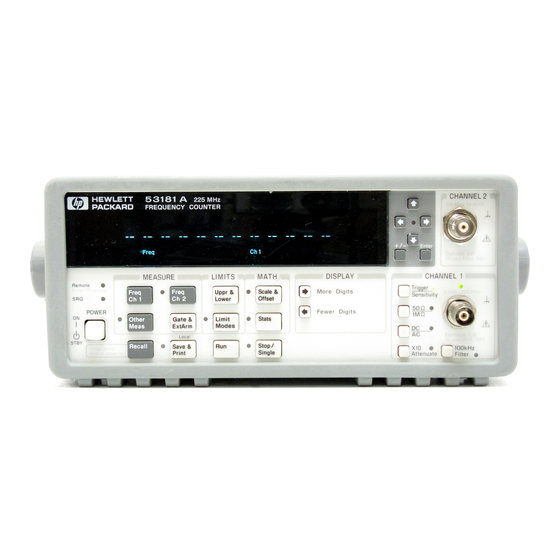
Agilent 53131A/132A/181A Counters
High-performance, low-cost counters simplify and
speed systems and bench frequency measurements
Data Sheet
Recommended replacement products:
53200 Series RF & universal frequency counter/timers
(Data sheet publication number: 5990-6283EN)
A family of universal and
RF counters to meet your needs
Agilent Technologies 53131A/132A/
181A high-performance counters give
you fast, precise frequency measure-
ments at an affordable price. These
counters feature an intuitive user
interface and one-button access to
frequently used functions so you can
make accurate measurements quickly
and easily.
 Loading…

Agilent 53131A/132A/181A Counters
High-performance, low-cost counters simplify and speed systems and bench frequency measurements
Data Sheet
Recommended replacement products:
53200 Series RF & universal frequency counter/timers
(Data sheet publication number: 5990-6283EN)
•225 MHz bandwidth
(optional 1.5, 3, 5, or 12.4 GHz)
•10or 12-digit resolution with
1 s gate time
•GPIB interface and IntuiLink connectivity software standard
•Data transfer rate of up to 200 fully formatted measurements/second
A family of universal and
RF counters to meet your needs
Agilent Technologies 53131A/132A/ 181A high-performance counters give you fast, precise frequency measurements at an affordable price. These counters feature an intuitive user interface and one-button access to frequently used functions so you can make accurate measurements quickly and easily.
Real-time digital signal processing technology is used to analyze data while simultaneously taking new readings, speeding measurement throughput. The technology, developed for Agilent’s high-end line of modulation domain analyzers, allows the counters to gather more data for each measurement, so you get higher-resolution measurements in a fraction of the time it takes other counters.
The 53131A/132A/181A counters offer built-in statistics and math functions so you can scale measurements and simultaneously measure and track average, min/max and standard deviation. Automated limit testing lets you set upper and lower limits for any measurement. An analog display mode lets you see at a glance whether a measurement is within pass/fail limits. The counters flag out-of-limit conditions and can generate an output signal to trigger external devices when a limit is exceeded. For quick access to frequently used tests, a single keystroke recalls up to 20 different stored frontpanel set-ups.
For computer-controlled systems applications, each counter includes a standard GPIB interface with full
SCPI-compatible programmability and a data transfer rate of up to 200 fully formatted measurements per second.
The standard RS-232 talk-only interface provides printer support or data transfer to a computer through a terminalemulation program.
Agilent 53131A universal counter
The two-channel 53131A counter offers 10 digits per second of frequency/ period resolution and a bandwidth of 225 MHz. Time interval resolution is specified at 500 ps. An optional third channel provides frequency measurements up to 3 GHz, 5 GHz, or 12.4 GHz. Standard measurements include frequency, period, ratio, time interval, pulse width, rise/fall time, phase angle, duty cycle, totalize, and peak voltage.
Agilent 53132A universal counter
For applications requiring higher resolution, the 53132A offers the same features and functions as the 53131A, with up to 12 digits/sec frequency/ period resolution and 150 ps time interval resolution. In addition, the 53132A offers advanced arming modes for time interval measurements.
Agilent 53181A RF counter
Optimized for RF applications, the single-channel 10 digit/s 53181A measures frequency, period and peak voltage. A digit-blanking function lets you easily eliminate unnecessary digits when you want to read measurements quickly. For higher-frequency measurements, choose an optional second channel that provides measurements up to 1.5 GHz, 3 GHz, 5 GHz, or 12.4 GHz. A self-guided shallow menu makes this counter exceptionally easy to use.
2

Agilent IntuiLink provides easy access to the counter’s data from your PC
The Agilent 53131A/132A/181A counters, capture precise frequency and time measurements. IntuiLink software allows that data to be put to work easily. You work in a familiar environment at all times, using PC applications such as Microsoft Excel® or Word® to analyze, interpret, display, print, and document the data you get from the counter.
It gives you the flexibility to configure and run tests from your PC making data gathering more convenient.
Agilent IntuiLink lets you:
•Configure tests, including measurement type, number of readings, measurement speed, and more.
•Choose display modes from realtime strip chart, histogram, readout, and table mode.
•Scale measurements data.
•Copy captured data to other programs.
Optional timebases offer increased stability
Optional timebases are available for 53131A/132A/181A counters to
increase measurement accuracy. Option 010 provides a high stability oven timebase with aging of less than
5 x 10⁻¹⁰ per day.
1-year warranty
Each counter comes with operating, programming and service manuals, IntuiLink software, a power cord and a full 1-year warranty.
Time Base
Internal time base stability (see graph 3 for timebase contribution of measurement error)
|
Standard |
Medium oven |
High oven |
Ultra high oven |
||
|
(0° to 50°C) |
(Option 001) |
(Option 010) |
(Option 012 for 53132A only) |
||
|
Temperature stability (referenced to 25°C) |
< 5 x 10⁻⁶ |
< 2 x 10⁻⁷ |
< 2.5 x 10⁻⁹ |
< 2.5 x 10⁻⁹ |
|
|
Aging rate |
Per Day: |
< 4 x 10⁻⁸ |
< 5 x 10⁻¹⁰ |
< 1 x 10⁻¹⁰ |
|
|
(after 30 days) |
Per Month: |
< 3 x 10⁻⁷ |
< 2 x 10⁻⁷ |
< 1.5 x 10⁻⁸ |
< 3 x 10⁻⁹ |
|
Per Year: |
< 2 x 10⁻⁸ |
||||
|
Turn-on stability vs. time |
|||||
|
(in 30 minutes) |
< 2 x 10⁻⁷ |
< 5 x 10⁻⁹ |
< 5 x 10⁻⁹ |
||
|
referenced to 2 h |
referenced to 24 h |
referenced to 24 h |
|||
|
Calibration |
Manual adjust |
Electronic |
Electronic |
Electronic |
Note that power to the time base is maintained when the counter is placed in standby via the front panel switch. The internal fan will continue to operate when in standby to maintain long-term measurement reliability.
3

Instrument Inputs
Input specifications
Channel 1 & 2 (53131A, 53132A)1
Channel 1 (53181A)
Frequency range
|
dc coupled |
dc to 225 MHz |
|
ac coupled |
1 MHz to 225 MHz (50 Ω) |
|
30 Hz to 225 MHz (1 MΩ) |
|
|
FM tolerance |
25% |
Voltage range and sensitivity (Sinusoid)2
|
dc to 100 MHz |
20 mVrms to ±5 V ac + dc |
|
100 MHz |
30 mVrms to ±5 V ac + dc |
|
to 200 MHz |
|
|
200 MHz |
40 mVrms to ±5 V ac + dc |
|
to 225 MHz |
(all specified at 75 mVrms |
|
with opt. rear connectors)3 |
Voltage range and sensitivity (Single-shot pulse)2
|
4.5 ns to 10 ns |
100 mVpp to 10 Vpp |
|
pulse width |
(150 mVpp with optional |
|
rear connectors)3 |
|
|
>10 ns |
50 mVpp to 10 Vpp |
|
pulse width |
(100 mVpp with optional |
|
rear connectors)3 |
|
|
Trigger level2 |
|
|
Range |
± 5.125 V |
|
Accuracy |
± (15 mV + 1% of trigger level) |
|
Resolution |
5 mV |
|
Damage level |
|
|
50 Ω |
5 Vrms |
|
0 to 3.5 kHz, |
350 Vdc + ac pk |
|
1 MΩ |
|
|
3.5 kHz to |
350 Vdc + ac pk linearly |
|
100 kHz, 1 MΩ |
derated to 5 Vrms |
|
>100 kHz, |
5 Vrms |
|
1 MΩ |
Input characteristics
Channel 1 & 2 (53131A, 53132A)1
Channel 1 (53181A)
|
Impedance |
1 MΩ or 50 Ω |
|
1 MΩ |
30 pF |
|
capacitance |
|
|
Coupling |
ac or dc |
|
Low-pass filter |
100 kHz, switchable |
|
-20 dB at > 1 MHz |
|
|
Input |
Selectable between Low, |
|
sensitivity |
Medium, or High (default). |
|
Low is approximately 2x |
|
|
High Sensitivity. |
|
|
Trigger slope |
Positive or negative |
|
Auto trigger level |
|
|
Range |
0 to 100% in 10% steps |
|
Frequency |
> 100 Hz |
|
Input amplitude |
> 100 mVpp |
|
(No amplitude modulation) |
|
|
Attenuator |
|
|
Voltage range |
x10 |
|
Trigger range |
x10 |
Input Specifications4
Channel 3 (53131A, 53132A)
Channel 2 (53181A)
Frequency range
|
Option 015 |
100 |
MHz to 1.5 GHz |
|
(for 53181A |
(see Opt. 030 for |
|
|
only) |
additional specs) |
|
|
Option 030 |
100 |
MHz to 3 GHz |
|
Option 050 |
200 |
MHz to 5 GHz |
|
Option 124 |
200 |
MHz to 12.4 GHz |
Power range and sensitivity (Sinusoid)
Option 030 100 MHz to 2.7 GHz: -27 dBm to +19 dBm
2.7 GHz to 3 GHz:
-21 dBm to +13 dBm
Option 050 200 MHz to 5 GHz: -23 dBm to +13 dBm
Option 124 200 MHz to 12.4 GHz -23 dBm to +13 dBm
Damage level
|
Option 030 |
5 Vrms |
|
Option 050 |
+25 dBm |
|
Option 124 |
+25 dBm |
|
4 |
Characteristics
|
Impedance |
50 Ω |
|
Coupling |
AC |
|
VSWR |
< 2.5:1 |
External arm input specifications5
Signal input range
TTL compatible
Timing Restrictions
|
Pulse width |
> 50 ns |
|
Transition time |
< 250 ns |
|
Start-to-stop time |
> 50 ns |
|
Damage level |
10 Vrms |
External arm input characteristics5
Input capacitance 17 pF
Start/stop slope Positive or negative
External time base input specifications
|
Voltage range |
200 mVrms to 10 Vrms |
|
Damage level |
10 Vrms |
|
Frequency |
1 MHz, 5 MHz, and 10 MHz |
|
(53132A 10 MHz only) |
Time base output specifications
|
Output frequency |
10 MHz |
|
Voltage |
> 1 Vpp into 50 Ω |
|
(centered around 0 V) |
1.Specifications and characteristics for Channels 1 and 2 are identical for both common and separate configurations.
2.Values shown are for X1 attenuator setting. Multiply all values by 10 (nominal) when using the X10 attenuator setting.
3.When the 53131A or 53132A are ordered with the optional rear terminals (Opt. 060), the channel 1 and 2 inputs are active on both front and rear of the counter. When the 53181A is ordered with the optional rear terminal, the channel 1 input is active on both front and rear of the counter. For this condition, specifications indicated for the rear connections also apply to the front connections.
4.When optional additional channels are ordered with Opt. 060, refer to configuration table for Opt. 060 under ordering info on page 8. There is no degradation in specifications for this input, as applicable.
5.Available for all measurements except peak volts. External arm is referred to as external gate for some measurements.
You can only view or download manuals with
Sign Up and get 5 for free
Upload your files to the site. You get 1 for each file you add
Get 1 for every time someone downloads your manual
Buy as many as you need
A_53132A A_53132A
User Manual: A_53132A
Open the PDF directly: View PDF ![]() .
.
Page Count: 13
Agilent 53131A/132A/181A Counters
High-performance, low-cost counters simplify and
speed systems and bench frequency measurements
Data Sheet
Recommended replacement products:
53200 Series RF & universal frequency counter/timers
(Data sheet publication number: 5990-6283EN)

• 225 MHz bandwidth
(optional 1.5, 3, 5, or 12.4 GHz)
• 10- or 12-digit resolution with
1 s gate time
• GPIB interface and IntuiLink
connectivity software standard
• Data transfer rate of up to 200 fully
formatted measurements/second

A family of universal and
RF counters to meet your needs
Agilent Technologies 53131A/132A/
181A high-performance counters give
you fast, precise frequency measurements at an affordable price. These
counters feature an intuitive user
interface and one-button access to
frequently used functions so you can
make accurate measurements quickly
and easily.

Real-time digital signal processing
technology is used to analyze data
while simultaneously taking new readings, speeding measurement throughput. The technology, developed for
Agilent’s high-end line of modulation
domain analyzers, allows the counters
to gather more data for each measurement, so you get higher-resolution
measurements in a fraction of the time
it takes other counters.

The 53131A/132A/181A counters offer
built-in statistics and math functions
so you can scale measurements and
simultaneously measure and track
average, min/max and standard deviation. Automated limit testing lets you
set upper and lower limits for any measurement. An analog display mode lets
you see at a glance whether a measurement is within pass/fail limits. The
counters flag out-of-limit conditions
and can generate an output signal to
trigger external devices when a limit
is exceeded. For quick access to frequently used tests, a single keystroke
recalls up to 20 different stored frontpanel set-ups.

For computer-controlled systems
applications, each counter includes
a standard GPIB interface with full
SCPI-compatible programmability and
a data transfer rate of up to 200 fully
formatted measurements per second.
The standard RS-232 talk-only interface
provides printer support or data transfer to a computer through a terminalemulation program.

Agilent 53132A universal counter
For applications requiring higher
resolution, the 53132A offers the same
features and functions as the 53131A,
with up to 12 digits/sec frequency/
period resolution and 150 ps time
interval resolution. In addition, the
53132A offers advanced arming modes
for time interval measurements.

Agilent 53131A universal counter
The two-channel 53131A counter offers
10 digits per second of frequency/
period resolution and a bandwidth of
225 MHz. Time interval resolution is
specified at 500 ps. An optional third
channel provides frequency measurements up to 3 GHz, 5 GHz, or 12.4 GHz.
Standard measurements include frequency, period, ratio, time interval,
pulse width, rise/fall time, phase
angle, duty cycle, totalize, and peak
voltage.

Agilent 53181A RF counter
Optimized for RF applications, the
single-channel 10 digit/s 53181A
measures frequency, period and peak
voltage. A digit-blanking function lets
you easily eliminate unnecessary digits
when you want to read measurements
quickly. For higher-frequency measurements, choose an optional second
channel that provides measurements
up to 1.5 GHz, 3 GHz, 5 GHz, or 12.4 GHz.
A self-guided shallow menu makes this
counter exceptionally easy to use.

2

Agilent IntuiLink provides easy access
to the counter’s data from your PC
The Agilent 53131A/132A/181A
counters, capture precise frequency
and time measurements. IntuiLink
software allows that data to be put
to work easily. You work in a familiar
environment at all times, using PC
applications such as Microsoft Excel®
or Word® to analyze, interpret, display,
print, and document the data you get
from the counter.

Agilent IntuiLink lets you:
• Configure tests, including measurement type, number of readings,
measurement speed, and more.
• Choose display modes from realtime strip chart, histogram, readout,
and table mode.

Optional timebases offer
increased stability
Optional timebases are available
for 53131A/132A/181A counters to
increase measurement accuracy. Option
010 provides a high stability oven
timebase with aging of less than
5 x 10⁻¹⁰ per day.
1-year warranty
Each counter comes with operating,
programming and service manuals,
IntuiLink software, a power cord and
a full 1-year warranty.

• Scale measurements data.
• Copy captured data to other
programs.

It gives you the flexibility to configure
and run tests from your PC making
data gathering more convenient.

Time Base
Internal time base stability (see graph 3 for timebase contribution of measurement error)
Standard
(0° to 50°C)

Medium oven
(Option 001)

High oven
(Option 010)

Ultra high oven
(Option 012 for 53132A only)

Temperature stability (referenced to 25°C)

< 5 x 10⁻⁶

< 2 x 10⁻⁷

< 2.5 x 10⁻⁹

< 2.5 x 10⁻⁹

Aging rate
(after 30 days)

< 3 x 10⁻⁷

< 4 x 10⁻⁸
< 2 x 10⁻⁷

< 5 x 10⁻¹⁰
< 1.5 x 10⁻⁸

< 1 x 10⁻¹⁰
< 3 x 10⁻⁹
< 2 x 10⁻⁸

< 2 x 10⁻⁷
referenced to 2 h

< 5 x 10⁻⁹
referenced to 24 h

< 5 x 10⁻⁹
referenced to 24 h

Electronic

Electronic

Electronic

Per Day:
Per Month:
Per Year:

Turn-on stability vs. time
(in 30 minutes)

Calibration

Manual adjust

Note that power to the time base is maintained when the counter is placed in standby via the front panel switch. The internal fan will continue to operate
when in standby to maintain long-term measurement reliability.

3

Instrument Inputs

Input specifications

Input characteristics

Channel 1 & 2 (53131A, 53132A)
Channel 1 (53181A)

1

Frequency range

Channel 1 & 2 (53131A, 53132A)
Channel 1 (53181A)

Impedance

50 Ω

Coupling

AC

Impedance

1 MΩ or 50 Ω

VSWR

< 2.5:1

dc coupled

dc to 225 MHz

1 MΩ
capacitance

30 pF

ac coupled

1 MHz to 225 MHz (50 Ω)
30 Hz to 225 MHz (1 MΩ)

Coupling

ac or dc

FM tolerance

25%

Voltage range and sensitivity (Sinusoid)2
30 mVrms to ±5 V ac + dc

200 MHz
to 225 MHz

40 mVrms to ±5 V ac + dc
(all specified at 75 mVrms
with opt. rear connectors)3

Voltage range and sensitivity
(Single-shot pulse)2
4.5 ns to 10 ns 100 mVpp to 10 Vpp
pulse width
(150 mVpp with optional
rear connectors)3
>10 ns
pulse width

50 mVpp to 10 Vpp
(100 mVpp with optional
rear connectors)3

External arm input specifications5

Low-pass filter 100 kHz, switchable
-20 dB at > 1 MHz
Input
sensitivity

dc to 100 MHz 20 mVrms to ±5 V ac + dc
100 MHz
to 200 MHz

Characteristics
1

Selectable between Low,
Medium, or High (default).
Low is approximately 2x
High Sensitivity.

Range

± 5.125 V

Accuracy

± (15 mV + 1% of trigger level)

Resolution

5 mV

Damage level
50 Ω

5 Vrms

0 to 3.5 kHz,
1 MΩ

350 Vdc + ac pk

3.5 kHz to
350 Vdc + ac pk linearly
100 kHz, 1 MΩ derated to 5 Vrms
>100 kHz,
1 MΩ

TTL compatible
Timing Restrictions
Pulse width

> 50 ns

Transition time

< 250 ns

Trigger slope Positive or negative

Start-to-stop time > 50 ns

Auto trigger level

Damage level

Range

0 to 100% in 10% steps

Frequency

> 100 Hz

Input amplitude > 100 mVpp
(No amplitude modulation)
Attenuator
Trigger range

10 Vrms

External arm input characteristics5
Impedance

1 kΩ

Input capacitance 17 pF
Start/stop slope Positive or negative

Voltage range x10
x10

External time base input specifications
Input Specifications4

Trigger level 2

Signal input range

Voltage range

200 mVrms to 10 Vrms

Damage level

10 Vrms

Channel 3 (53131A, 53132A)
Channel 2 (53181A)

Frequency

1 MHz, 5 MHz, and 10 MHz
(53132A 10 MHz only)

Frequency range

Time base output specifications

Option 015
(for 53181A
only)

100 MHz to 1.5 GHz
(see Opt. 030 for
additional specs)

Option 030

100 MHz to 3 GHz

Option 050

200 MHz to 5 GHz

Option 124

200 MHz to 12.4 GHz

Power range and sensitivity (Sinusoid)
Option 030

5 Vrms

100 MHz to 2.7 GHz:
-27 dBm to +19 dBm
2.7 GHz to 3 GHz:
-21 dBm to +13 dBm

Option 050

200 MHz to 5 GHz:
-23 dBm to +13 dBm

Option 124

200 MHz to 12.4 GHz
-23 dBm to +13 dBm

Damage level
Option 030

5 Vrms

Option 050

+25 dBm

Option 124

+25 dBm

4

Output frequency 10 MHz
Voltage

> 1 Vpp into 50 Ω
(centered around 0 V)

1. Specifications and characteristics for Channels
1 and 2 are identical for both common and
separate configurations.
2. Values shown are for X1 attenuator setting.
Multiply all values by 10 (nominal) when using
the X10 attenuator setting.
3. When the 53131A or 53132A are ordered with
the optional rear terminals (Opt. 060), the channel
1 and 2 inputs are active on both front and rear
of the counter. When the 53181A is ordered with
the optional rear terminal, the channel 1 input is
active on both front and rear of the counter. For
this condition, specifications indicated for the rear
connections also apply to the front connections.
4. When optional additional channels are ordered
with Opt. 060, refer to configuration table for
Opt. 060 under ordering info on page 8. There is
no degradation in specifications for this input,
as applicable.
5. Available for all measurements except peak volts.
External arm is referred to as external gate for
some measurements.

For automatic or external arming:
(and signals < 100 Hz using timed arming)
tres

LSD displayed:

×

Gate time

RMS resolution:

Frequency
or
period

t 2res + (2 × Trigger error) 2

×

Gate time

53131A tres

53132A tres

Frequency
or
period

53181A tres

typical
650 ps
200 ps
650 ps
see graphs for worst case resolution performance
N
For automatic arming: Gate time =
Frequency
where N = 1 for standard channel frequency < 1 MHz
4 for standard channel frequency > 1 MHz
128 for optional channel

Systematic uncertainty:

± Time base error ±

t acc

×

Gate time

53131A tacc

53132A tacc

350 ps

100 ps

350 ps

1.25 ns

500 ps

1.25 ns

Typical
Worst case

Frequency
or
period

53181A tacc

Trigger: Default setting is auto trigger at 50%

For time or digits arming:

LSD displayed:
RMS resolution
(see graph 2):

2
Gate time ×
4×

2

× tres

Number of samples

+

t 2res + (2 ×Trigger error 2)

Gate time ×

53131A/181A
tres
tjitter

Number of samples

tjitter
Gate time

+

tjitter
Gate time

×

Frequency
or
period

×

Frequency
or
period

53132A
tres
tjitter

500 ps
50 ps
225 ps
3 ps
Typical
See graphs for worst case resolution performance
Number of samples = Gate time × Frequency (Frequency < 200 kHz)
Gate time × 200,000

Systematic uncertainty:
53131A/181A
tacc

± Time base error ±

(Frequency > 200 kHz)
t acc
Gate time

53132A
tacc

Typical

100 ps

10 ps

Worst case

300 ps

100 ps

Trigger: Default setting is auto trigger at 50%

5

×

Frequency
or
period

Measurement Specifications

Frequency (53131A, 53132A, 53181A)

Phase (53131A, 53132A)

Peak volts (53131A, 53132A, 53181A)

Channel 1 and 2 (53131A, 53132A)
Channel 1 (53181A)

Measurement is specified over the
full signal range of Channels 1 and 2.

Range

Results range -180° to +360°

Measurement is specified on Channels 1 and 2
for dc signals; or for ac signals of frequencies
between 100 Hz and 30 MHz with peak-to-peak
amplitude greater than 100 mV.

0.1 Hz to 225 MHz

Channel 3 (53131A, 53132A)
Channel 2 (53181A)
Option 015
100 MHz to 1.5 GHz
(53181 A only)
Option 030

100 MHz to 3 GHz

Option 050

200 MHz to 5 GHz

Option 124

200 MHz to 12.4 GHz

Results range -5.1 V to +5.1 V

Duty cycle (53131A, 53132A)

Resolution

Measurement is specified over the full
signal range of Channel 1. However, both the
positive and negative pulse widths must be
greater than 4 ns.

Peak volts systematic uncertainty

Results range 0 to 1 (e.g. 50% duty cycle
would be displayed as .5)

Use of the input attenuator multiplies all
voltage specifications (input range, results
range, resolution and systematic uncertainty)
by a nominal factor of 10.

Rise/fall time (53131A, 53132A)

Gate time

Measurement is specified over the full signal
ranges of Channel 1. The interval between the
end of one edge and start of a similar edge
must be greater than 4 ns.

Auto mode, or 1 ms to 1000 s

Edge selection Positive or negative

GPIB ASCII

(Period 2 or 3 selectable via GPIB only)

Period (53131A, 53132A, 53181A)
Channel 1 and 2 (53131A, 53132A)
Channel 1 (53181A)
Range

4.44 ns to 10 s

Channel 3 (53131A, 53132A)
Channel 2 (53181A)

Trigger

Option 015
0.66 ns to 10 ns
(53181A only)

Results range 5 ns to 10 5 s

Option 030

0.33 ns to 10 ns

Option 050

0.2 ns to 5 ns

Option 124

80 ps to 5 ns

Frequency ratio (53131A, 53132A, 53181A)
Measurement is specified over the full signal
range of each input.
Results range

10

-10

to 10

11

“Auto” gate time 100 ms

Default setting is auto trigger
at 10% and 90%

10 mV

for ac signals: 25 mV + 10% of V
for dc signals: 25 mV + 2% of V

Measurement throughput
200 measurements/s (maximum)

Measurement arming
Start
measurement

Free run, manual, or external

Stop
measurement

Continuous, single, external,
or timed

Pulse width (53131A, 53132A)

Time interval

100 µs to 10 s (53131A)

Measurement is specified over the full signal
range of Channel 1. The width of the opposing
pulse must be greater than 4 ns.

Delayed
arming

100 ns to 10 s (53132A)

Pulse selection Positive or negative

Arming modes

Trigger

(Note that not all arming modes are available
for every measurement function.)

LSD

500 ps (53131A)/150 ps
(53132A)

Default setting is auto trigger
at 50%

Results range 5 ns to 10 5 s

Time interval (53131A, 53132A)

LSD

500 ps (53131A)/150 ps
(53132A)

Measurement is specified over the full signal
ranges6 of Channels 1 and 2.
5

Results range -1 ns to 10 s

Totalize (53131A, 53132A)

LSD

Measurement is specified over the
full signal range of Channel 1.

500 ps (53131A)/150 ps
(53132A)

Results range 0 to 10 15
Resolution

± 1 count

6

5. Available for all measurements except peak volts.
External arm is referred to as external gate for some
measurements.
6. See specifications for pulse width and rise/fall time
measurements for additional restrictions on signal
timing characteristics.

Time interval, pulse width, rise/fall time (53131A and 53132A only):
RMS resolution:

(tres) 2 + Start trigger error 2 + Stop trigger error 2

Systematic uncertainty:

± (Time base error × Measurement) Trigger level timing error ± 1.5 ns Differential channel error (53131A)
± (Time base error × Measurement) Trigger level timing error ± 900 ps Differential channel error (53132A)
where tres = 750 ps for the 53131A, 300 ps for the 53132A

Frequency ratio:
LSD: Ratio 12 :

Ch1 , Ch1 , Ch2 , Ch3
(53131A and 53132A)
Ch2 Ch3 Ch1 Ch1
1
Ch2 Freq × Gate time

RMS Resolution: Ratio 12 :
2

Ratio 1 :

2×

2

Ratio 1 :

Ch1 , Ch2
(53181A)
Ch2 Ch1

Ch2 Freq
(Ch1 Freq) 2 × Gate time

1 + (Ch1 Freq × Ch2 Trigger error) 2
Ch2 Freq × Gate time

2 × Ch2 Freq × 1 + (Ch1 Freq × Ch2 Trigger error) 2
(Ch1 Freq) 2 × Gate time

For measurements using Ch3,
substitute Ch3 for Ch2 in these
equations. To minimize relative
phase measurement error,
connect the higher frequency
signal to channel 1.

Systematic uncertainty: ± 2x resolution

Phase (53131A and 53132A)
RMS resolution:

((Tres)2

+ (2 x Trigger error 2)) ×

1+

Phase

2

× Frequency × 360°

360°

Systematic uncertainty:

( ± Trigger level timing error ± 1.5 ns Differential channel error) × Frequency × 360° (53131A)
( ± Trigger level timing error ± 900 ps Differential channel error) × Frequency × 360° (53132A)

Duty cycle (53131A and 53132A)
RMS resolution:
tres

((Tres)2 +

53131A

53132A

750 ps

300 ps

(2 × Trigger error 2)) × (1 + Duty cycle 2) × Frequency

Auto arming: Measurements are initiated
immediately and acquired as fast as possible,
using a minimum number of signal edges.
Timed arming: The duration of the measurement
is internally timed to a user-specified value
(also known as the “gate time”).
Digits arming: Measurements are performed
to the requested resolution (number of digits)
through automatic selection of the acquisition
time.
External arming: An edge on the external arm
Input enables the start of each measurement.
Auto arming, timed arming modes or another
edge on the external arm input may be used to
complete the measurement.

Time interval delayed arming: For time interval
measurements, the stop trigger condition is
inhibited for a user-specified time following the
start trigger. The 53132A offers advanced time
interval arming capabilities including use of user
specified time or Channel 2 events to delay both
start and stop triggers.

Measurement limits
Limit checking: The measurement value is
checked against user-specified limits at the
end of each measurement.
Display modes: The measurement result may
be displayed as either the traditional numeric
value or graphically as an asterisk moving
between two vertical bars.

7

Out-of-limits Indications:
• The limits annunciator will light on the front
panel display.
• The instrument will generate an SRQ if
enabled via GPIB.
• The limits hardware signal provided via the
RS-232 connector will go low for the duration
of the out-of-limit condition.
• If the analog display mode is enabled, the
asterisk appears outside the vertical bars,
which define the upper and lower limits.

Fractional time base error (see graph 3)
Time base error is the maximum fractional frequency variation of the time base due to aging or
fluctuations in ambient temperature or line voltage:
Time base error =

(

)

∆f
∆f
∆f
— Aging rate + — Temperature + — Line voltage
f
f
f

Multiply this quantity by the measurement result to yield the absolute error for that measurement.
Averaging measurements will not reduce (fractional) time base error. The counters exhibit negligible
sensitivity to line voltage; consequently the line voltage term may be ignored.

Trigger error
External source and input amplifier noise may advance or delay the trigger points that define the
beginning and end of a measurement. The resulting timing uncertainty is a function of the slew rate
of the signal and the amplitude of spurious noise spikes (relative to the input hysteresis band).
The (rms) trigger error associated with a single trigger point is:

Trigger error =

(E input ) 2 + (E signal ) 2
Input signal slew rate at trigger point

(in seconds)

where
Einput = RMS noise of the input amplifier: 1 mVrms (350 µVrms typical). Note that the internal
measurement algorithms significantly reduce the contribution of this term.
Esignal = RMS noise of the input signal over a 225 MHz bandwidth (100 kHz bandwidth when the
low-pass filter is enabled). Note that the filter may substantially degrade the signal’s slew rate at
the input of the trigger comparator.
For two-trigger-point measurements (e.g. rise time, pulse width), the trigger errors will be referred
to independently as start trigger error and stop trigger error.

Trigger level timing error (see graph 6)
Trigger level timing error results from a deviation of the actual trigger level from the specified level.
The magnitude of this error depends on resolution and accuracy of the trigger level circuit, input
amplifier fidelity, input signal slew rate, and width of the input hysteresis band.
The following equations should be summed together to obtain the overall trigger level timing error.
At the “High” sensitivity input setting, the hysteresis band can be assumed to be the sensitivity of
the counter input (see page 2). Reduction of input sensitivity or use of the attenuator will increase the size of this band.
Input hysteresis error:
Trigger level setting error: ±

0.5 x hysteresis band
Input signal slew rate at start trigger point

0.5 x hysteresis band

–

Input signal slew rate at stop trigger point

15 mV ± (1% x start trigger level setting)
Input signal slew rate at start trigger point

±

15 mV ± (1% x stop trigger level setting)
Input signal slew rate at stop trigger point

Differential channel error
The differential channel error term stated in several systematic uncertainty equations accounts for
channel-to-channel mismatch and internal noise. This error can be substantially reduced by performing
a TI calibration (accessible via the utility menu) in the temperature environment in which future
measurements will be made.

8

Graph 1:
Agilent 53131A/181A–Worst case
RMS resolution7
(Automatic or external arming)

1E + 02

Auto armed

The graphs may also be used to compute errors
for period measurements. To find the period
error (DP), calculate the frequency of the input
signal (F = 1/P) and find the frequency error
(DF) from the chart.
Then calculate the period error as:

∆P =

∆F
F

×

Frequency error (Hz)

1E + 00
1E – 02
1E – 04

1 ms
1E – 06

100 ms

1E – 08
P

10 s

10 ms

Gate
time

1s

1E – 10
10

100

1000

10000

1E + 05 1E + 06

1E + 07

1E + 08

1E + 09

1E + 10

Input frequency (Hz)

Graph 2:
Agilent 53131A/181A–Worst case
RMS resolution7
(Time or digits arming)

E + 02

Frequency error (Hz)

1E + 00
1E – 02
1E – 04

10 ms

1 ms

1E – 06

1s

1E – 08

100 ms

Gate
time

10 s
1E – 10
10

100

1000

10000

1E + 05 1E + 06

1E + 07

1E + 08

1E + 09

1E + 10

Input frequency (Hz)

Time or digit arming
Frequency error +

4

× 2 × Trigger error
× Number of samples

Gate time

×

Frequency
or
period

10 kHz
1 kHz
100 Hz
10 Hz
1 Hz
100 mHz
10 mHz
1 mHz
100 µHz
10 µHz
1 µHz
100 nHz
10 nHz

Standard T.B.
1 year after cal

High stability T.B.
10 years after cal

Standard T.B.
1 month after cal
High stability T.B.
1 year after cal
High stability T.B.
1 month after cal
1 Hz
1 ns

10 Hz
10 ns

Automatic or external arming
Frequency error +

2

× Trigger error
Gate time

Medium T.B.
1 year after cal

100 Hz
100 ns

1 kHz
1 µs

Medium T.B.
1 month after cal

Ultra stability T.B.
1 year after cal

10 kHz 100 kHz
10 µs 100 µs

1 MHz
1 ms

10 MHz 100 MHz
10 ms 100 ms

Input signal frequency or time
×

Frequency
or
period

9

1 GHz
1 sec

10 µs
1 µs
100 ns
10 ns
1 ns
100 ps
10 ps
1 ps
100 fs
10 fs
1 fs
100 as
10 as

Time error

7. Graphs 1, 2, 4 and 5 do not reflect the effects of
trigger error. To place an upper bound on the added
effect of this error term, determine the frequency
error from the appropriate graph and add a trigger
error term as follows:

Frequency error

Graph 3:
Timebase error

1E + 02

Graph 4:
Agilent 53132A–Worst case
RMS resolution7
(Automatic or external arming)

Auto armed

Frequency error (Hz)

1E + 00
1E – 02
1E – 04

1 ms
1E – 06

100 ms 10 ms
1s

Gate
time

1E – 08

10 s
1E – 10
10

100

1000

10000

1E + 05

1E + 06

1E + 07 1E + 08

1E + 09

1E + 10

Input frequency (Hz)

Graph 5:
Agilent 53132A–Worst case
RMS resolution7
(Time or digits arming)

E + 02

1 ms
Frequency Error (Hz)

1E + 00
1E – 02
1E – 04
1E – 06

100 ms

1E – 08

10 ms

Gate
time

1s
10 s

1E – 10
10

100

1000

10000

1E + 05

1E + 06

1E + 07 1E + 08

1E + 09

1E + 10

Input frequency (Hz)

100 µs

Graph 6:
Trigger level timing error
(Level setting error and
input hysteresis)

200 to 225 MHz rep. rate

7. Graphs 1, 2, 4 and 5 do not reflect the effects of
trigger error. To place an upper bound on the added
effect of this error term, determine the frequency
error from the appropriate graph and add a trigger
error term as follows:

Trigger error per trigger point

10 µs
100 to 200 MHz rep. rate
1 µs

dc to 100 MHz rep. rate

100 ns
10 ns
Pulse and T.I. at 5 V trigger point
1 ns
Pulse and T.I. at 2.5 V trigger point
100 ps
Pulse and T.I. at 0 V trigger point

Time or digit arming
Frequency error +

10 ps
4

× 2 × Trigger error
× Number of samples

Gate time

×

Frequency
or
period

1 V/ms

10 mV/µs

2

× Trigger error
Gate time

×

Frequency
or
period

1 V/µs

10 mV/ns

100 mV/ns

Input signal slew rate at trigger point

Automatic or external arming
Frequency error +

100 mV/µs

10

1 V/ns

10 mV/ps

Measurement
Statistics

General
Information

Available statistics

Save and recall

Environment

Mean, Minimum, Maximum, Standard Deviation

Up to 20 complete instrument setups may
be saved and recalled later. These setups
are retained when power is removed from
the counter.

0°C to 55°C operating
–40°C to 71°C storage

Number of measurements 2 to 1,000,000.
Statistics may be collected on all measurements
or on only those which are between the limit
bands. When the limits function is used in
conjunction with statistics, N (number of
measurements) refers to the number of in-limit
measurements. In general, measurement
resolution will improve in proportion to N,
up to the numerical processing limits of
the instrument.

Rack dimensions (HxWxD)

Remote Interface
GPIB (IEEE 488.1-1987,
IEEE 488.2-1987)

88.5 mm x 212.6 mm x 348.3 mm
Remote programming language
Weight
3.5 kg maximum

SCPI-1992.0 (Standard Commands
for Programmable Instruments)

Warranty

Safety

Measurements

1 year

Statistics may be collected for all measurements
except peak volts and totalize.

Designed in compliance with IEC-1010,
UL-3111-1 (draft), CAN/CSA 1010.1

Power supply
100 to 120 VAC ± 10% -50, 60 or
400 Hz ± 10% 220 to 240 VAC
± 10% -50 or 60 Hz ± 10%

EMC
CISPR-11, EN50082-1,
IEC 801-2, -3, -4

ac Line selection

Radiated immunity testing

Automatic

When the product is operated at maximum
sensitivity (20 mVrms) and tested at 3 V/m
according to IEC 801-3, external 100 to 200 MHz
electric fields may cause frequency miscounts.

Power requirements
170 VA maximum (30 W typical)

11

Ordering
Information
53131A

Other options

10 digit/s, 500 ps universal counter

Opt. 001

Medium-stability timebase

Opt. 010

High-stability timebase

Opt. 012

Ultra-high stability timebase
(53132A only)

Opt. 015

1.5 GHz RF input Ch 2
for 53181A only

Opt. 030

3 GHz RF input Ch 3
(Ch 2 on 53181A)

Opt. 050

5 GHz RF input
with type N connector
Ch 3 (Ch 2 on 53181A)

Opt. 124

12.4 GHz RF input
with type N connector
Ch 3 (Ch 2 on 53181A)

53132A
12 digit/s, 150 ps universal counter

53181A
10-digit/s RF counter

Accessories included
Each counter comes with IntuiLink software,
standard timebase, and power cord. CD with
the following: IntuiLink software, Operating,
Programming, Service and Getting Started
Guides, a data sheet, and application notes.

Manual options
(please specify one when ordering)

Opt. 060

Rear-panel connectors*

Opt. A6J

ANSI Z540 compliant calibration

103.6 mm
374.0 mm

212.6 mm

88.5 mm
348.3 mm

*Opt 060 configuration table

ABA

US English

53131A/132A
Ch1 & Ch2 front & rear (in parallel)

ABD

German

Ch3

Opt. 030 rear only, front plugged

ABE

Spanish

Ch3

Opt. 050/124 front only

ABF

French

Ch2

Opt. 050/124 front only

ABJ

Japanese

ABZ

Italian

53181
Ch1

front & rear (in parallel)

ABO

Taiwan Chinese

Ch2

Opt. 015/030 rear only, front plugged

AB1

Korean

Ch2

Opt. 050/124 front only

AB2

Chinese

Accessories
34131A
34161A
34190A

34191A

34194A

12

254.4 mm

Hard carrying case
Accessory pouch
Rackmount kit: designed for use
with only one instrument, mounted
on either the left or the right side of
the rack.
2U dual flange kit: secures the
instrument to the front of the
rack. This kit can be used with the
34194A dual lock link kit to mount
two half-width, 2U height instruments side-by side.
Dual lock link kit: recommended
for side-by-side combinations and
includes links for instruments of different depths. This kit can be used
with the 34191A 2U dual flange kit
to mount two half-width, 2U height
instruments side-by-side.

www.agilent.com
www.agilent.com/find/counters

Agilent Email Updates

www.agilent.com/find/emailupdates
Get the latest information on the
products and applications you select.

www.axiestandard.org
AdvancedTCA® Extensions for
Instrumentation and Test (AXIe) is
an open standard that extends the
AdvancedTCA for general purpose
and semiconductor test. Agilent
is a founding member of the AXIe
consortium.

Agilent Advantage Services is committed
to your success throughout your equipment’s lifetime. To keep you competitive,
we continually invest in tools and
processes that speed up calibration and
repair and reduce your cost of ownership.
You can also use Infoline Web Services
to manage equipment and services more
effectively. By sharing our measurement
and service expertise, we help you create
the products that change our world.
www.agilent.com/find/advantageservices

www.lxistandard.org
LAN eXtensions for Instruments
puts the power of Ethernet and
the Web inside your test systems.
Agilent is a founding member of the
LXI consortium.

www.pxisa.org
PCI eXtensions for Instrumentation
(PXI) modular instrumentation
delivers a rugged, PC-based highperformance measurement and
automation system.

Agilent Channel Partners
www.agilent.com/find/channelpartners
Get the best of both worlds: Agilent’s
measurement expertise and product
breadth, combined with channel
partner convenience.

www.agilent.com/quality

For more information on Agilent
Technologies’ products, applications or
services, please contact your local Agilent
office. The complete list is available at:
www.agilent.com/find/contactus
Americas
Canada
Brazil
Mexico
United States

(877) 894 4414
(11) 4197 3500
01800 5064 800
(800) 829 4444

Asia Pacific
Australia
1 800 629 485
China
800 810 0189
Hong Kong
800 938 693
India
1 800 112 929
Japan
0120 (421) 345
Korea
080 769 0800
Malaysia
1 800 888 848
Singapore
1 800 375 8100
Taiwan
0800 047 866
Other AP Countries (65) 375 8100
Europe & Middle East
Belgium
32 (0) 2 404 93 40
Denmark
45 70 13 15 15
Finland
358 (0) 10 855 2100
France
0825 010 700*
*0.125 €/minute

Germany
49 (0) 7031 464 6333
Ireland
1890 924 204
Israel
972-3-9288-504/544
Italy
39 02 92 60 8484
Netherlands
31 (0) 20 547 2111
Spain
34 (91) 631 3300
Sweden
0200-88 22 55
United Kingdom 44 (0) 131 452 0200
For other unlisted countries:
www.agilent.com/find/contactus
Revised: June 8, 2011

Product specifications and descriptions
in this document subject to change
without notice.
© Agilent Technologies, Inc. 2006, 2011
Published in USA, November 8, 2011
5967-6039EN
Source Exif Data:
File Type                       : PDF
File Type Extension             : pdf
MIME Type                       : application/pdf
PDF Version                     : 1.3
Linearized                      : Yes
XMP Toolkit                     : 3.1-701
Producer                        : Acrobat Distiller 7.0 (Windows)
Creator Tool                    : Adobe InDesign CS5 (7.0.3)
Modify Date                     : 2011:11:22 14:41:24-08:00
Create Date                     : 2011:11:22 14:41:24-08:00
Format                          : application/pdf
Title                           : 5967-6039EN 11-08-11.indd
Creator                         : jfox
Document ID                     : uuid:f683f757-6dc3-414d-b1dc-caada480b3fd
Instance ID                     : uuid:b391b7d5-01d4-4853-a498-a9bacf3e5824
Page Count                      : 13
Author                          : jfox
EXIF Metadata provided by EXIF.tools
-
Contents
-
Table of Contents
-
Troubleshooting
-
Bookmarks
Related Manuals for HP 53132A
Summary of Contents for HP 53132A
-
Page 1
Assembly-Level Service Guide HP 53131A/132A/181A 225 MHz Counter… -
Page 3
Assembly-Level Service Guide This guide describes how to service the HP 53131A and HP 53132A Universal Counters, and the HP 53181A Frequency Counter. The information in this guide applies to instruments having the number prefix listed below, unless accompanied by a “Manual Updating Changes”… -
Page 4
If HP receives notice from the mains power source to of such defects during the the product’s ground circuitry. warranty period, HP will, at its option, either repair or replace WARNING products which prove to be Indicates earth (ground) WHEN MEASURING POWER defective. -
Page 5: Table Of Contents
Introduction Operational Verification Complete Performance Tests Optional HP-IB Verification Recommended Calibration Cycle Test Record Equipment Required HP 53131A/132A/181A Operational Verification Power-On Self Tests Run Self Test Termination Check External Arm Test (HP 53131A/132A Only) 1-10 Equipment 1-10 Assembly-Level Service Guide…
-
Page 6
Procedure 1-11 External Timebase Tests 1-12 Equipment 1-12 1 MHz External Timebase Input (HP 53131A and HP 53181A Only) 1-13 5 MHz External Timebase Input (HP 53131A and HP 53181A Only) 1-14 10 MHz External Timebase Input (HP 53131A and HP… -
Page 7
Sensitivity (HP 53131A/132A Only) 1-30 Equipment 1-30 Counter Setup 1-30 100 MHz to 2.5 GHz Sensitivity for HP 53131A/132A Option 030 only 1-31 2.7 to 3.0 GHz Sensitivity for Option 030 only 1-32 200 MHz to 5.0 GHz Sensitivity for HP 53131A/132A… -
Page 8
Only) 1-51 Equipment 1-51 Counter Setup 1-51 100 kHz to 100 MHz Sensitivity for HP 53181A 1-52 100 MHz to 200 MHz Sensitivity for HP 53181A 1-54 200 MHz to 225 MHz Sensitivity for HP 53181A 1-54 Test 3: Channel 1 Frequency Accuracy (HP 53181A… -
Page 9
Contents Minimum to Maximum Accuracy Test for Options 030/050/ 1-65 Equipment 1-65 Counter Setup 1-65 Procedure 1-66 Test 6: Peak Volts, Channel 1 (HP 53181A Only) 1-68 Equipment 1-68 Counter Setup 1-68 Procedure 1-69 HP 53181A HP-IB Verification Program (Optional) -
Page 10
To Calibrate the High Stability Timebase Option (Medium, High, or Ultra-High) 2-24 About the HP 53181A Calibration Menu 2-25 Overview of the HP 53181A Calibration Menu 2-25 The HP 53181A Calibration Menu Tree 2-27 To View the Calibration Menu and Security Status… -
Page 11
Contents Surface Mount Repair 2-38 Disassembly and Reassembly Specifics 2-38 After Service Considerations 2-39 Product Safety Checks 2-39 Product Performance Checks 2-39 Assembly Identification and Location 2-40 Troubleshooting the Counter 2-45 Power Supply Check 2-45 Overview of the Self-Test Routines 2-47 Diagnosing the Faulty Assembly by Using the Self Tests… -
Page 12
Contents Retrofitting Options Introduction Tools Required Do This First To Retrofit A3 1.5/3.0/5.0/12.4 GHz Channel Assembly (Option 015/030/050/124) To Retrofit A5 DC Power Input Assembly (Option 002) Option 002 DC Power Input Assembly Parts Preliminary Procedure Retrofitting Procedure To Retrofit A6 High Stability Timebase Assembly (Options 001, 010, and 012) 4-11 Option 001 Medium Stability Timebase Assembly… -
Page 13
Contents Cabinet Parts and Hardware Backdating Introduction Manual Changes Older Instruments Backdating Hardware Backdating Firmware Backdating Specifications 6-16 HP 53131A/132A Specifications Introduction Instrument Inputs Time Base Measurement Specifications Measurement Definitions 7-12 Measurement Arming and Processing 7-14 General Information 7-16 HP 53181A Specifications… -
Page 14
Contents Assembly-Level Service Guide… -
Page 15: Preface
Instrument Identification Instrument identification is made from the serial number on the rear panel of the Counter. HP uses a two-part serial number with the first part (prefix) identifying a series of instruments and the second part (suffix) identifying a particular instrument within a series. An HP-assigned alpha character between the prefix and suffix identifies the country in which the instrument was manufactured.
-
Page 16: Instruments Covered By This Guide
Preface Instruments Covered by this Guide This guide applies directly to HP 53131A, HP 53132A, and HP 53181A Counters that have the same serial number prefix(es) shown on the title page. If the serial number prefix of your Counter differs from that listed on the title page of this guide, then there may be differences between this guide and your instrument.
-
Page 17: How To Order Guides
Chapter 7, “HP 53131A/132A Specifications,” lists all the specifications and operating characteristics for the HP 53131A/132A Universal Counter. Chapter 8, “HP 53181A Specifications,” lists all the specifications and operating characteristics for the HP 53181A Frequency Counter. How to Order Guides…
-
Page 18: Description Of The 225 Mhz Counters
HP-IB measuring speed of 200 measurements per second, and is suitable for bench-top operation and lower-volume ATE operation. The frequency and time interval resolutions for the HP 53132A are up to 12 digits in one second and 150 picoseconds, respectively. The HP 53132A provides users with exceptional resolution, and is ideal for ATE systems operation.
-
Page 19
SCPI programming capability, and • analog display mode limit testing Programmable control is performed via an HP-IB. The HP-IB and a talk-only RS-232C serial port are standard for the HP 53131A/132A/181A. The serial port is for printing measured and analyzed data on serial printers, or for outputting an out-of-limit signal. -
Page 20: Options
For the HP 53131A/132A Option 030, front and rear terminals can exist for Channel 1 and 2. The optional Channel 3 can be configured as rear terminals only or front terminals only. For the HP 53181A, front and rear terminals can exist for Channel 1. The optional Channel 2 can be configured as rear terminals only or front terminals only.
-
Page 21: Support
5-year Return to HP for Calibration, Option W52 Accessories Supplied and Available Accessories Supplied • Power cord, 2.3 meters Accessories Available • HP 34161A Accessory Pouch • Printer RS-232 Interface cables, HP 24542G or HP 24542H • HP-IB cables, HP 10833A/B/C/D Assembly-Level Service Guide…
-
Page 22
Preface Assembly-Level Service Guide… -
Page 23
Performance Tests Verifying Specifications… -
Page 24: Performance Tests Introduction
This chapter provides procedures to test the electrical performance of the HP 53131A/132A Universal Counter and HP 53181A Frequency Counter, using the specifications listed in Chapter 7, “HP 53131A/132A Specifications,” and Chapter 8, “HP 53181A Specifications,” of this guide. Three types of testing are provided: •…
-
Page 25: Complete Performance Tests
The HP-IB verification program, described on page 1-40 (HP 53131A/132A) or page 1-70 (HP 53181A), exercises the Counter via the HP-IB interface. The program is written for an HP 9000 series 200 or 300 Desktop Computer as the controller. If the instrument successfully completes all phases of the verification program, there is a very high probability that the HP-IB interface is working properly.
-
Page 26: Equipment Required
HP 3325B OV, P, T Synthesized Signal Generator 100 kHz to 2560 MHz HP 8663A OV, P, T Pulse Generator 5 ns pulse width HP 8130A or equivalent OV, C Sweep Oscillator 3.0 GHz HP 8340B P, T Primary Frequency Standard Absolute accuracy >1 x 10…
-
Page 27: Hp 53131A/132A/181A Operational Verification
Chapter 1 Performance Tests HP 53131A/132A/181A Operational Verification HP 53131A/132A/181A Operational Verification The operational verification is an abbreviated series of checks that may be performed to give a high degree of confidence that the instrument is operating properly without performing the complete performance tests.
-
Page 28
For HP 53131A/132A, mark Pass or Fail in the HP 53131A/132A Performance Test Record on page 1-41, Test 1. 6’ For HP 53181A, mark Pass or Fail in the HP 53181A Performance Test Record on page 1-71, Test 1. Connect the Counter’s rear-panel 10 MHz Out as shown in Figure 1-1A or Figure 1-1B, depending on which Counter you are testing. -
Page 29
Test Record on page 1-71, Test 2. NOTE The remaining steps apply to the HP 53131A and HP 53132A only since the HP 53181A does not have a standard Channel 2 input. For the HP 53181A, proceed to the following “Run Self Test” section. -
Page 30: Run Self Test
HP 3458A BNC — to — Dual Counter Digital Multimeter Banana Plug HP 53131A/132A is shown in above figure. This setup for the HP 53181A requires a connection to Channel 1 only. Figure 1-2. Termination Check Setup Assembly-Level Service Guide…
-
Page 31
For HP 53131A/132A, mark Pass or Fail in the HP 53131A/132A Performance Test Record on page 1-41, Test 5a. 6’ For HP 53181A, mark Pass or Fail in the HP 53181A Performance Test Record on page 1-71, Test 4a. Press Channel 1 50Ω/1MΩ key. -
Page 32: External Arm Test (Hp 53131A/132A Only)
Chapter 1 Performance Tests HP 53131A/132A/181A Operational Verification External Arm Test (HP 53131A/132A Only) This test verifies the External Arm port of the HP 53131A and HP 53132A Counter is operational. Equipment HP 8663A Synthesized Signal Generator HP 8130A Pulse Generator (or equivalent) HP 10100C 50Ω…
-
Page 33: Procedure
Connect the equipment as shown in Figure 1-3. HP 8130A Pulse Generator Output HP 8663A 50Ω Synthesized Signal Generator Feedthrough Ext Arm (rear panel) Counter Channel 1 Output N-to-BNC Connector Figure 1-3. External Arm Test Setup (HP 53131A/132A Only) Assembly-Level Service Guide 1-11…
-
Page 34: External Timebase Tests
Chapter 1 Performance Tests HP 53131A/132A/181A Operational Verification Set the HP 8663A to output a 200 MHz, 100 mV sine wave signal to Channel 1. On the Counter, Press Run key. Send a single pulse by pressing the MAN key on the HP 8130A, and observe that with each press the Gate annunciator flashes.
-
Page 35: Mhz External Timebase Input
Ref In input of the Counter via a 50Ω feedthrough) to output a 1 MHz, 200 mV rms sine wave signal. Set Synthesizer #2 (i.e., the HP 3325B connected to Channel 1) to output a 2 MHz, 100 mV rms square wave signal.
-
Page 36: Mhz External Timebase Input
Chapter 1 Performance Tests HP 53131A/132A/181A Operational Verification 5’ For HP 53181A, mark Pass or Fail in the HP 53181A Performance Test Record on page 1-71, Test 5a. 5 MHz External Timebase Input (HP 53131A and HP 53181A Only) Change the frequency of Synthesizer # 1, which is connected to the Counter’s rear-panel Ref In input to 5 MHz.
-
Page 37: 10 Mhz External Timebase Input For The Hp 53132A
10 MHz External Timebase Input for the HP 53132A Connect the equipment as shown in Figure 1-4. Set Synthesizer #1 (i.e., the HP 3325B that is connected to the rear-panel Ref In input of the Counter via a 50Ω feedthrough) to output a 10 MHz, 200 mV rms sine wave signal.
-
Page 38: Hp 53131A/132A Complete Performance Tests
The specifications of the HP 53131A/132A Universal Counter can be verified by performing the performance tests provided in this section. Table 1-2 lists a summary of the HP 53131A/132A performance tests. Record the results of the performance tests in the appropriate place on HP 53131A/132A Performance Test Record, which starts on page 1-41.
-
Page 39: Test 1: Time Interval (Hp 53131A/132A Only)
Chapter 1 Performance Tests Test 1: Time Interval (HP 53131A/132A Only) Test 1: Time Interval (HP 53131A/132A Only) This test verifies the Time Interval specifications between Channels 1 and 2. Equipment HP 8130A Pulse Generator (or equivalent) HP 10503A BNC Cable Counter Setup Cycle the POWER key to preset the Counter.
-
Page 40: Procedure
The HP 53132A Counter should display 0.1500 µs ±0.0025 µs. Record this value in the appropriate place in the Performance Test Record (Test 1, Line 1 for HP 53131A or Test 1, Line 2 for HP 53132A). Disconnect the test setup.
-
Page 41: Test 2: Trigger Level (Hp 53131A/132A Only)
Chapter 1 Performance Tests Test 2: Trigger Level (HP 53131A/132A Only) Test 2: Trigger Level (HP 53131A/132A Only) This test verifies the Trigger Level accuracy of the HP 53131A and HP 53132A Universal Counters. Equipment HP 3325B Synthesizer HP 10503A BNC Cable Counter Setup Cycle the POWER key to preset the Counter.
-
Page 42: Procedure
Channel 2 Output Figure 1-6. Trigger Level Test Setup Set the HP 3325B to output a 1 MHz, 80 mVp-p square wave signal. Set the HP 3325B DC OFFSET to −60 mV. On the Counter, press Run key. Now, increment the dc offset on the HP 3325B by +1 mV until the Counter’s Gate annunciator flashes and continue incrementing…
-
Page 43
Set the HP 3325B DC OFFSET to +60 mV. On the Counter, press Run key. Now, decrement the offset on the HP 3325B by −1 mV until the Counter’s Gate annunciator flashes and continue decrementing until the Counter displays a stable reading of approximately 1 MHz. -
Page 44: Test 3: Channels 1 And 2 Frequency Sensitivity (Hp 53131A/132A Only)
Chapter 1 Performance Tests Test 3: Channels 1 and 2 Frequency Sensitivity (HP 53131A/132A Only) Test 3: Channels 1 and 2 Frequency Sensitivity (HP 53131A/132A Only) This set of tests verifies frequency sensitivity specifications of the HP 53131A and 53132A Universal Counters.
-
Page 45: 100 Khz To 100 Mhz Sensitivity For Hp 53131A/132A
Figure 1-7. For this test, make sure you always use the unit (HP 53131A/132A or HP 8663A) that contains the better 10 MHz timebase as the output source as shown in Figure 1-7.
-
Page 46
Chapter 1 Performance Tests Test 3: Channels 1 and 2 Frequency Sensitivity (HP 53131A/132A Only) Set the HP 8663A Signal Generator to output a 100 MHz, −35.0 dBm sine wave signal (−20.0 dBm for Option 060 Rear Terminals) to the Counter’s Channel 1 input. -
Page 47: 100 Mhz To 200 Mhz Sensitivity For Hp 53131A/132A
Chapter 1 Performance Tests Test 3: Channels 1 and 2 Frequency Sensitivity (HP 53131A/132A Only) Record the actual reading in the appropriate place in the Performance Test Record (Test 3, Line 2). If you are testing a Counter with front-panel terminals (Standard), record the reading on Line 2 of the Standard portion of the test record.
-
Page 48: 200 Mhz To 225 Mhz Sensitivity For Hp 53131A/132A
Chapter 1 Performance Tests Test 3: Channels 1 and 2 Frequency Sensitivity (HP 53131A/132A Only) Repeat steps 1 through 4 for Channel 1. Record the actual reading in the Performance Test Record (Test 3, Line 4). 200 MHz to 225 MHz Sensitivity for HP 53131A/132A Leave the signal generator connected to Channel 1.
-
Page 49: Test 4: Channels 1 And 2 Frequency Accuracy (Hp 53131A/132A Only)
Chapter 1 Performance Tests Test 4: Channels 1 and 2 Frequency Accuracy (HP 53131A/132A Only) Test 4: Channels 1 and 2 Frequency Accuracy (HP 53131A/132A Only) This set of tests verifies the frequency accuracy specifications of the HP 53131A and HP 53132A Universal Counters.
-
Page 50: Procedure
Verify the HP 53131A Counter reads 1 MHz ±1 mHz. Verify the HP 53132A Counter reads 1 MHz ±200 µHz. Record the actual reading in the appropriate place in the Performance Test Record (Test 4, Line 1 for HP 53131A or Test 4, Line 3 for HP 53132A. 1-28…
-
Page 51
Verify the HP 53132A Counter reads 100 MHz ±15 mHz. Record the actual reading in the appropriate place in the Performance Test Record (Test 4, Line 5 for HP 53131A or Test 4, Line 7 for HP 53132A). Change the signal generator frequency to 200 MHz. -
Page 52: Test 5: Option 030/050/124 Channel 3 Frequency Sensitivity (Hp 53131A/132A Only)
Frequency Sensitivity (HP 53131A/132A Only) This test verifies the frequency range, and sensitivity of the optional 3-GHz and 5-GHz Channel 3 (Option 030/050/124) for the HP 53131A and the HP 53132A Universal Counters. Equipment HP 8663A Synthesized Signal Generator (not needed for Option 050)
-
Page 53: Mhz To 2.5 Ghz Sensitivity For Hp 53131A/132A Option 030 Only
100 MHz to 2.5 GHz Sensitivity for HP 53131A/132A Option 030 only Set the HP 8663B Synthesized Signal Generator to output a 2500 MHz, −40 dBm sine wave, and connect the signal to Channel 3 of the Counter as shown in Figure 1-9.
-
Page 54: To 3.0 Ghz Sensitivity For Option 030 Only
2.7 to 3.0 GHz Sensitivity for Option 030 only Disconnect the HP 8663A Synthesized Signal Generator from the Counter (see Figure 1-9), and connect the HP 8340B Sweep Oscillator to Channel 3 of the Counter. Change the settings of the Sweep Oscillator to 3.0 GHz, −40 dBm.
-
Page 55
Chapter 1 Performance Tests Test 5: Option 030/050/124 Channel 3 Frequency Sensitivity (HP 53131A/132A Only) 200 MHz to 5.0 GHz Sensitivity for HP 53131A/132A (Option 050 only) Connect the 8340B Sweep Oscillator to Channel 3 of the counter. Change the settings of the Sweep Oscillator to 5.0 GHz, −40 dBm. -
Page 56
Chapter 1 Performance Tests Test 5: Option 030/050/124 Channel 3 Frequency Sensitivity (HP 53131A/132A Only) 200 MHz to 12.4 GHz Sensitivity for HP 53131A/132A (Option 124 only) Connect the 8340B Sweep Oscillator to Channel 3 of the counter. Change the settings of the Sweep Oscillator to 12.4 GHz, −40 dBm. -
Page 57: Test 6: Option 030/050/124 Channel 3 Frequency Accuracy (Hp 53131A/132A Only)
Connect equipment as shown in Figure 1-9. (NOTE: For Options 050 and 124, skip steps 2 through 5. Proceed to step 6.) Set the HP 8663A Synthesized Signal Generator to output 100 MHz at −17.0 dBm. Assembly-Level Service Guide 1-35…
-
Page 58
Verify the HP 53132A Counter reads 100 MHz ±20 mHz. Record the actual reading in the Performance Test Record (Test 6, Line 1 for HP 53131A or Test 6, Line 2 for HP 53132A). Disconnect the HP 8663A output from Channel 3 of the Counter, and connect the HP 8340B Sweep Oscillator output to Channel 3 of the Counter as shown in Figure 1-9. -
Page 59: Test 7: Peak Volts, Channels 1 And 2 (Hp 53131A/132A Only)
Test 7: Peak Volts, Channels 1 and 2 (HP 53131A/132A Only) Test 7: Peak Volts, Channels 1 and 2 (HP 53131A/132A Only) This test verifies the Peak Volts accuracy specification of the HP 53131A and HP 53132A Universal Counters. Equipment HP 3325B Synthesizer HP 10100C 50Ω…
-
Page 60: Volt Peak
Output Figure 1-10. Peak Volts Test Setup Set the HP 3325B to output a 2 MHz, 2 Vp-p sine wave. The Counter should display −1.00 ±0.12V for the negative peak of the sine wave. This reading is displayed on the left side of the display.
-
Page 61: Volt Peak
Chapter 1 Performance Tests Test 7: Peak Volts, Channels 1 and 2 (HP 53131A/132A Only) Volt Peak 2 Remove the signal from Channel 1 of the Counter and connect it to Channel 2. Press Other Meas key until VOLT PEAK 2 is displayed.
-
Page 62
HP-IB interface. If the Counter successfully completes all phases of the verification program, there is a high probability that the HP-IB interface is operating correctly. If the Counter fails the verification program, refer to the troubleshooting section in Chapter 2, “Service,”… -
Page 63: Hp 53131A/132A Performance Test Record
1 MHz External Timebase Input Test (HP 53131A Only) 5 MHz External Timebase Input Test (HP 53131A Only) 10 MHz External Timebase Input Test (HP 53131A Only) 10 MHz External Timebase Input Test for the HP 53132A Assembly-Level Service Guide 1-41…
-
Page 64
+15 mV −15 mV Channel 2 2. __________ +15 mV (HP 53131A/132A Only) Test 3: Channels 1 and 2 Frequency Sensitivity (HP 53131A/132A Only) Standard (Front Panel Terminals) Actual Reading Specification ≤ −21 dBm (20 mVrms) 100 kHz–100 MHz, Channel 1 1. -
Page 65
Chapter 1 Performance Tests HP 53131A/132A Performance Test Record (Page 3 of 6) HP 53131A/132A Performance Test Record (Page 3 of 6) Complete Performance Tests (Continued) Test Actual Number Test Description Minimum Reading Maximum Channels 1 and 2 Frequency Accuracy… -
Page 66
15. __________ 225.000,000,035 MHz Channel 2 224.999,999,965 MHz 16. __________ 225.000,000,035 MHz Test 5: Option 030/050/124 Channel 3 Frequency Sensitivity (HP 53131A/132A Only) Actual Reading Specification ≤ −27 dBm 10 mV rms 100 MHz–2.5 GHz 1. __________ ≤ −21 dBm 20 mV rms 2.7–3.0 GHz… -
Page 67
Chapter 1 Performance Tests HP 53131A/132A Performance Test Record (Page 5 of 6) HP 53131A/132A Performance Test Record (Page 5 of 6) Complete Performance Tests (Continued) Test Actual Number Test Description Minimum Reading Maximum Option 030 Channel 3 Frequency Accuracy… -
Page 68
Chapter 1 Performance Tests HP 53131A/132A Performance Test Record (Page 6 of 6) HP 53131A/132A Performance Test Record (Page 6 of 6) Complete Performance Tests (Continued) Test Actual Number Test Description Minimum Reading Maximum 12.4 GHz Test (HP 53131A): Channel 3 12.399.999 992 MHz… -
Page 69: Hp 53181A Complete Performance Tests
HP 53181A Complete Performance Tests HP 53181A Complete Performance Tests The specifications of the HP 53181A Frequency Counter can be verified by performing the performance tests provided in this section. Table 1-3 lists a summary of the HP 53181A performance tests.
-
Page 70: Test 1: Trigger Level (Hp 53181A Only)
Chapter 1 Performance Tests Test 1: Trigger Level (HP 53181A Only) Test 1: Trigger Level (HP 53181A Only) This test verifies the Trigger Level accuracy of the HP 53181A Frequency Counter. Equipment HP 3325B Synthesizer HP 10503A BNC Cable Counter Setup Cycle the POWER key to preset the Counter.
-
Page 71: Procedure
Channel 1 Output Figure 1-11. Trigger Level Test Setup Set the HP 3325B to output a 1 MHz, 80 mVp-p square wave signal. Set the HP 3325B DC OFFSET to −60 mV. On the Counter, press Run key. Now, increment the dc offset on the HP 3325B by +1 mV until the Counter’s Gate annunciator flashes and continue incrementing…
-
Page 72
On the Counter, press Run key. Set the HP 3325B DC OFFSET to +60 mV. Now, decrement the offset on the HP 3325B by −1 mV until the Counter’s Gate annunciator flashes and continue decrementing until the Counter displays approximately 1 MHz. -
Page 73: Test 2: Channel 1 Frequency Sensitivity (Hp 53181A Only)
Chapter 1 Performance Tests Test 2: Channel 1 Frequency Sensitivity (HP 53181A Only) Test 2: Channel 1 Frequency Sensitivity (HP 53181A Only) This set of tests verifies frequency sensitivity specifications of the HP 53181A Frequency Counter. Equipment HP 8663A Synthesized Signal Generator HP 1250-0780 Type N-to-BNC Connector HP 10100C 50Ω…
-
Page 74: Khz To 100 Mhz Sensitivity For Hp 53181A
N-to-BNC Connector Figure 1-12. Channels 1 Frequency Sensitivity Test Setup Set the HP 8663A Signal Generator to output a 100 kHz, −35.0 dBm sine wave signal (−20.0 dBm for Option 060) to the Counter’s Channel 1 input. In 0.1 dB steps, increase the power level until the Counter displays a stable reading of 100 kHz.
-
Page 75
Chapter 1 Performance Tests Test 2: Channel 1 Frequency Sensitivity (HP 53181A Only) Sweep the frequency from 100 kHz to 100 MHz. For Option 060, sweep frequencies from 100 kHz to 225 MHz. The Counter should read frequencies from 100 kHz to 100 MHz at an input power level of ≤… -
Page 76: Mhz To 200 Mhz Sensitivity For Hp 53181A
Chapter 1 Performance Tests Test 2: Channel 1 Frequency Sensitivity (HP 53181A Only) 100 MHz to 200 MHz Sensitivity for HP 53181A Change the signal generator settings to 110 MHz at −30 dBm. Increase the power level by 0.1 dB steps until the Counter displays a stable 110 MHz reading.
-
Page 77: Test 3: Channel 1 Frequency Accuracy (Hp 53181A Only)
Chapter 1 Performance Tests Test 3: Channel 1 Frequency Accuracy (HP 53181A Only) Test 3: Channel 1 Frequency Accuracy (HP 53181A Only) This set of tests verifies the frequency accuracy specifications of the HP 53181A Frequency Counter. Equipment HP 8663A Synthesized Signal Generator…
-
Page 78: Procedure
Channel 1 N-to-BNC Connector Figure 1-13. Channels 1 Frequency Accuracy Test Setup Set the HP 8663A Signal Generator to output 1 MHz at −7 dBm. On the Counter, press Run key. Verify the Counter reads 1 MHz ±1 mHz. 1-56…
-
Page 79
Chapter 1 Performance Tests Test 3: Channel 1 Frequency Accuracy (HP 53181A Only) Record the actual reading in the Performance Test Record (Test 3, Line 1). Change the signal generator frequency to 100 MHz. Verify the Counter reads 100 MHz ±70 mHz. -
Page 80: Test 4: Option 015/030/050/124 Channel 2 Frequency Sensitivity
This test verifies the frequency range and sensitivity of the optional 1.5-GHz (Option 015), 3-GHz (Option 030), 5.0-GHz (Option 050), or 12.4-GHz (Option 124) Channel 2 for the HP 53181A Frequency Counter. Equipment HP 8663A Synthesized Signal Generator (Not needed for Option 050/124)
-
Page 81: Mhz To 1.5 Ghz Sensitivity For Option 015 Only
Test 4: Option 015/030/050/124 Channel 2 Frequency Sensitivity 100 MHz to 1.5 GHz Sensitivity for Option 015 Only Set the HP 8663B Synthesized Signal Generator to output a 500 MHz, −60 dBm sine wave and connect the signal to Channel 2 of the Counter as shown in Figure 1-14.
-
Page 82: Mhz To 2.7 Ghz Sensitivity For Option 030 Only
(Test 4, Line 1). 100 MHz to 2.7 GHz Sensitivity for Option 030 Only Set the HP 8663B Synthesized Signal Generator to output a 500 MHz, −60 dBm sine wave, and connect the signal to Channel 3 of the Counter as shown in Figure 1-14.
-
Page 83: To 3.0 Ghz Sensitivity For Option 030 Only
2.8 to 3.0 GHz Sensitivity for Option 030 Only Disconnect the HP 8663A Synthesized Signal Generator from the Counter (see Figure 1-14), and connect the HP 8340B Sweep Oscillator to Channel 3 of the Counter. Change the settings of the Sweep Oscillator to 3.0 GHz, −40 dBm.
-
Page 84: Mhz To 12.4 Ghz Sensitivity For Option 124 Only
Chapter 1 Performance Tests Test 4: Option 015/030/050/124 Channel 2 Frequency Sensitivity 200 MHz to 12.4 GHz Sensitivity for Option 124 only Connect the 8340B Sweep Oscillator to Channel 2 of the counter. Change the settings of the Sweep Oscillator to 12.4 GHz, −30 dBm. Increase the power level in 1 dB steps until the Counter displays a stable reading of approximately 12.4 GHz.
-
Page 85: Test 5: Option 015/030/050/124 Channel 2 Frequency Accuracy (Hp 53181A Only)
Frequency Accuracy (HP 53181A Only) This test verifies the frequency accuracy of the optional 1.5-GHz (Option 015), 3-GHz (Option 030), 5.0 GHz (Option 050), or 12.4 GHz (Option 124) Channel 2 for the HP 53181A Frequency Counter. The tests are organized as follows: •…
-
Page 86: Procedure
Chapter 1 Performance Tests Test 5: Option 015/030/050/124 Channel 2 Frequency Accuracy (HP 53181A Only) Procedure Connect equipment as shown in Figure 1-15. Frequency Standard HP 8340B (switch set to EXT) Sweep Oscillator Output Input (rear panel) HP 8663A Synthesized Signal Generator HP 53181A 50Ω…
-
Page 87: Hp 1250-0780 Type N-To-Bnc Connector
Disconnect the test setup. Minimum to Maximum Accuracy Test for Options 030/050/124 Equipment HP 8663A Synthesized Signal Generator (not needed for Option 050) HP 8340B Sweep Oscillator HP 1250-0780 Type N-to-BNC Connector (not needed for Option 050) HP 10503A BNC Cable (2) HP 10100C 50Ω…
-
Page 88: Procedure
Record the actual reading in the Performance Test Record (Test 5, Line 3). Disconnect the HP 8663A output from Channel 2 of the Counter, and connect the HP 8340B Sweep Oscillator output to Channel 2 of the Counter as shown in Figure 1-15.
-
Page 89
Test 5: Option 015/030/050/124 Channel 2 Frequency Accuracy (HP 53181A Only) (NOTE: For Options 050/124) Set the HP 8340B to output 5.0 GHz at −17 dBm. Verify the HP 53181A Counter reads 5.0 GHz ±3 Hz. Record the actual reading in the Performance Test Record (Test 5, Line 5). -
Page 90: Hp 10503A Bnc Cable
Chapter 1 Performance Tests Test 6: Peak Volts, Channel 1 (HP 53181A Only) Test 6: Peak Volts, Channel 1 (HP 53181A Only) This test verifies the Peak Volts accuracy specification of the HP 53181A Frequency Counter. Equipment HP 3325B Synthesizer HP 10100C 50Ω…
-
Page 91: Procedure
Output Figure 1-16. Peak Volts Test Setup Set the HP 3325B to output a 2 MHz, 2 Vp-p sine wave, and connect the signal to Channel 1 of the Counter. The Counter should display −1.00 ±0.12V for the negative peak of the sine wave.
-
Page 92: Hp 53181A Hp-Ib Verification Program (Optional)
(Optional) The HP-IB Verification program exercises the HP 53181A through various operating modes via the its HP-IB interface. If the Counter successfully completes all phases of the verification program, there is a high probability that the HP-IB interface is operating correctly. If the Counter fails the verification program, refer to the troubleshooting section in Chapter 2, “Service,”…
-
Page 93: Hp 53181A Performance Test Record
Chapter 1 Performance Tests HP 53181A Performance Test Record (Page 1 of 4) HP 53181A Performance Test Record (Page 1 of 4) Hewlett-Packard Model 53181A Frequency Counter Serial Number: _________________________ Repair/Work Order No. _ _ ________________ Test Performed By: _____________________ Temperature: __________________________…
-
Page 94
Chapter 1 Performance Tests HP 53181A Performance Test Record (Page 2 of 4) HP 53181A Performance Test Record (Page 2 of 4) Complete Performance Tests Test Number Test Description Minimum Actual Reading Maximum Trigger Level: −15 mV Channel 1 1. __________ +15 mV −15 mV… -
Page 95
HP 53181A Performance Test Record (Page 3 of 4) HP 53181A Performance Test Record (Page 3 of 4) Complete Performance Tests Test 4: Option 015/030/050 Channel 2 Frequency Sensitivity (HP 53181A Only) Actual Reading Specification ≤ −27 dBm 100 MHz–1.5 GHz (Option 015 Only) 1. -
Page 96
Chapter 1 Performance Tests HP 53181A Performance Test Record (Page 4 of 4) HP 53181A Performance Test Record (Page 4 of 4) Complete Performance Tests Test Actual Number Test Description Minimum Reading Maximum Peak Volts, Channel 1 (HP 53181A Only): −1.12 V… -
Page 97
Service… -
Page 98: Introduction
The HP 53131A/132A Calibration Procedures (page 2-15). This section provides step-by-step procedures for calibrating the HP 53131A/132A. • About the HP 53181A Calibration Menu (page 2-25). This section contains reference information that gives a complete overview of the calibration menu of the HP 53181A. •…
-
Page 99: Returning The Instrument To Hewlett-Packard For Service
Returning the Instrument to Hewlett-Packard for Service To Provide Repair Information If you are shipping the instrument to an HP office for service or repair, call your nearest Hewlett-Packard Sales Office to make arrangements. Then tag and package the HP 53131A/132A/181A for shipment.
-
Page 100: To Pack In The Original Packaging Materials
Chapter 2 Service Returning the Instrument to Hewlett-Packard for Service To Pack in the Original Packaging Materials Whenever possible, repack the instrument in its original packaging for shipment. In any correspondence, refer to the instrument by the model number and complete serial number. Disconnect the power cord, probes, cables, or other accessories attached to the instrument.
-
Page 101: To Pack In The Commercially Available Materials
Chapter 2 Service Returning the Instrument to Hewlett-Packard for Service To Pack in the Commercially Available Materials If the factory packaging materials are not available, you can use commercially available materials for shipping. Wrap the instrument in heavy paper or plastic. Place the instrument in a strong shipping container.
-
Page 102: About The Hp 53131A/132A Calibration Menu
Counter is shipped from the factory. If you forget your security code, you can reset the security code to the model-number default by resetting all of the non-volatile memory to a default state (Contact HP for this confidential procedure).
-
Page 103
(CODE?) NOTE A good precaution is to use an HP-IB program (see the programming example titled “To Read and Store Calibration Data” in Chapter 3 of the Programming Guide) to read and store the calibration factors prior to initiating any calibration. -
Page 104: The Hp 53131A/132A Calibration Menu Tree
Turn power off, press and hold Scale & Offset key, then press POWER key to access this menu. This menu does not exist in early versions (firmware revisions 3317, 3335, and 3402) of the HP 53131A/132A. In the early versions of the Counter, the CAL: menu item resides in the Utility menu, and there is no calibration security capability.
-
Page 105: To View The Calibration Menu And Security Status
Chapter 2 Service About the HP 53131A/132A Calibration Menu To View the Calibration Menu and Security Status The Calibration menu is accessed by holding the Scale & Offset key and cycling the POWER key. The first item in the Calibration menu is a message indicating the calibration security status: CAL SECURE or CAL UNSECURE .
-
Page 106
Chapter 2 Service About the HP 53131A/132A Calibration Menu Press any one of the arrow keys until your calibration choice (that is, CAL: OFFS2? , CAL: GAIN 1? , CAL: GAIN 2? , CAL: TI QUIK? , CAL: TI FINE? , or CAL: TIMEBAS? ) is displayed. -
Page 107
CAL: TI QUIK? calibration instead, or restore the calibration factors that you saved prior to starting. Equipment: HP 8130A Pulse Generator or equivalent. HP 59992A J06 Time Interval Calibrator or equivalent. Assembly-Level Service Guide 2-11… -
Page 108
Procedure: From the front-panel calibration menu, one keypress invokes the calibration. You are prompted to press buttons on the HP 59992A J06 Calibrator for each part of a four-part calibration. Note that CAL: TI FINE? requires the completion of four steps in order. -
Page 109: To Secure Against Calibration
Chapter 2 Service About the HP 53131A/132A Calibration Menu To Secure Against Calibration Press and hold Scale & Offset key, then cycle POWER key. CAL UNSECURE is displayed. If CAL SECURE is displayed, then the Counter is already secured against calibration and the remaining steps are not applicable.
-
Page 110: To View The Calibration Count
Chapter 2 Service About the HP 53131A/132A Calibration Menu To View the Calibration Count Press and hold Scale & Offset key, then cycle POWER key. Press Scale & Offset key until CAL COUNT? is displayed. Press any one of the entry keys (arrow, +/-, Enter) to have a scrolling message appear, indicating what the calibration count is.
-
Page 111: The Hp 53131A/132A Calibration Procedures
Chapter 2 Service The HP 53131A/132A Calibration Procedures The HP 53131A/132A Calibration Procedures First Determine the Counter Firmware Revision Press and hold Recall (Utility) key, then cycle POWER key. REV: n is displayed; where “n” represents the numeric firmware revision code.
-
Page 112
Chapter 2 Service The HP 53131A/132A Calibration Procedures Press the appropriate arrow keys to enter the security code “ 53131 ”, for example, if 53131 is the security code by performing the following steps: a. Press key four times. The Counter should display CODE: 00000 . -
Page 113
Chapter 2 Service The HP 53131A/132A Calibration Procedures Press Enter key. The Counter momentarily displays CALIBRATING , and then it should display OFFS 1 PASS . If the fail message is displayed, refer to the troubleshooting section in this chapter. -
Page 114: To Calibrate The Gain For Channels 1 And 2
Chapter 2 Service The HP 53131A/132A Calibration Procedures To Calibrate the Gain for Channels 1 and 2 Press any one of the arrow keys until CAL: GAIN 1 ? is displayed. Press Enter key. A scrolling message is displayed. Follow the instruction by performing the following steps.
-
Page 115: To Calibrate Time Interval
Chapter 2 Service The HP 53131A/132A Calibration Procedures To calibrate the gain for Channel 2, connect the input or the BNC Tee to Channel 2 of the Counter. Press any one of the arrow keys until CAL: GAIN 2 ? is displayed.
-
Page 116: Cal: Ti Quik? Calibration
Press Enter key. A scrolling message with instructions appears. Follow the instruction by performing the following procedure Connect the HP 8130A Pulse Generator output to Channel 1 of the Counter as shown in Figure 2-3. Equipment HP 8130A Pulse Generator (or equivalent)
-
Page 117: Cal: Ti Fine? Calibration
“To Calibrate the High Stability Timebase Option (Medium, High, or Ultra-High)” procedure (page 2-24) to calibrate the timebase. CAL: TI FINE? Calibration Connect the HP 8130A Pulse Generator, HP 59992A J06 Time Interval Calibrator, and HP 53131A/123A Counter as shown in Figure 2-4.
-
Page 118
A scrolling message with instructions appears. Follow the instruction by performing the following procedure. Note the Counter display message prompts you to press buttons on the HP 59992A J06 Calibrator for each part of a four-part calibration. Note that CAL: TI FINE? requires the completion of four steps in the proper order. -
Page 119: To Calibrate The Standard Timebase
Chapter 2 Service The HP 53131A/132A Calibration Procedures To Calibrate the Standard Timebase Connect the output of a 10 MHz house standard to Channel 1 of the Counter as shown in Figure 2-5. House Standard 10 MHz Reference HP 53131A/132A…
-
Page 120: To Calibrate The High Stability Timebase Option (Medium High, Or Ultra-High)
Chapter 2 Service The HP 53131A/132A Calibration Procedures To Calibrate the High Stability Timebase Option (Medium, High, or Ultra-High) NOTE Allow the Counter to warm up for approximately 24 hours before performing this calibration. This calibration is unlikely to fail, unless the Counter is not warmed up.
-
Page 121: About The Hp 53181A Calibration Menu
NOTE If you are familiar with the information provided in this section, proceed to the section titled “The HP 53181A Calibration Procedures” (page 2-31) to calibrate your Counter. This section, “About the HP 53181A Calibration Menu,” can be used as a reference.
-
Page 122
(CODE?) NOTE A good precaution is to use an HP-IB program (see the programming example titled “To Read and Store Calibration Data” in Chapter 3 of the Programming Guide) to read and store the calibration factors prior to initiating any calibration. -
Page 123: The Hp 53181A Calibration Menu Tree
Chapter 2 Service About the HP 53181A Calibration Menu The HP 53181A Calibration Menu Tree NOTE Turn power off, press and hold Scale & Offset key, then press POWER key to access this menu. POWER Scale & Offset On / Stby…
-
Page 124: To View The Calibration Menu And Security Status
Chapter 2 Service About the HP 53181A Calibration Menu To View the Calibration Menu and Security Status The Calibration menu is accessed by holding the Scale & Offset key and cycling the POWER key. The first item in the Calibration menu is a message indicating the calibration security status: CAL SECURE or CAL UNSECURE .
-
Page 125: To Initiate The Calibration Routines
Chapter 2 Service About the HP 53181A Calibration Menu To Initiate the Calibration Routines Press and hold Scale & Offset key, then cycle POWER key. Unsecure for calibration by performing the preceding procedure. Press Scale & Offset key until CAL: OFFS1? is displayed.
-
Page 126: To Change To New The Security Code
Chapter 2 Service About the HP 53181A Calibration Menu To Change to New the Security Code Press and hold Scale & Offset key, then cycle POWER key. Unsecure for calibration by the using the procedure described in the section titled “To Unsecure for Calibration.”…
-
Page 127: The Hp 53181A Calibration Procedures
Chapter 2 Service The HP 53181A Calibration Procedures The HP 53181A Calibration Procedures First Determine the Counter Firmware Revision Press and hold Recall (Utility) key, then cycle POWER key. REV: n is displayed; where “n” represents the numeric firmware revision code.
-
Page 128
Chapter 2 Service The HP 53181A Calibration Procedures c. Press key once, and then press key three times. The Counter should display CODE: 53000 . d. Press key once, and then press key once. The Counter should display CODE: 53100 . -
Page 129: To Calibrate The Gain For Channel 1
Press Enter key. A scrolling message is displayed. Follow the instruction by performing the following steps. Connect a BNC tee connector to Channel 1 of the HP 53181A. Connect the Counter, dc power supply, and digital multimeter shown in Figure 2-6.
-
Page 130: To Calibrate The Standard Timebase
Chapter 2 Service The HP 53181A Calibration Procedures Disconnect the calibration setup. This completes the Gain Calibration procedure. Depending on which timebase the Counter contains, proceed to either the following procedure “To Calibrate the Standard Timebase” or the “To Calibrate the High Stability Timebase Option (Medium, High, or Ultra-High)”procedure (page 2-35) to calibrate the timebase.
-
Page 131: To Calibrate The High Stability Timebase Option (Medium High, Or Ultra-High)
Chapter 2 Service The HP 53181A Calibration Procedures To Calibrate the High Stability Timebase Option (Medium, High, or Ultra-High) NOTE Allow the Counter to warm up for approximately 24 hours before performing this calibration. This calibration is unlikely to fail, unless the Counter is not warmed up.
-
Page 132: Pre-Troubleshooting Information
Chapter 2 Service Pre-Troubleshooting Information Pre-Troubleshooting Information This section contains the following pertinent troubleshooting information: • Safety Considerations • Recommended Test Equipment • Repair Considerations • After Service Considerations • Assembly Identification and Location Safety Considerations Although this instrument has been designed in accordance with international safety standards, this guide contains information, cautions, and warnings which must be followed to ensure safe operation and to retain the instrument in a safe condition.
-
Page 133: Recommended Test Equipment
(for example, fire and electric shock). Recommended Test Equipment Test equipment recommended for testing and troubleshooting the HP 53131A/132A/181A is listed in Chapter 1, “Performance Tests.” Substitute equipment may be used if it meets or exceeds the required characteristics listed in Table 1-1.
-
Page 134: Repair Considerations
Chapter 2 Service Pre-Troubleshooting Information Repair Considerations Electrostatic Discharge Electronic components and assemblies in the HP 53131A/132A/181A can be permanently degraded or damaged by electrostatic discharge. Use the following precautions when servicing the instrument: ENSURE that static-sensitive devices or assemblies are serviced at static-safe work stations providing proper grounding for service personnel.
-
Page 135: After Service Considerations
Chapter 2 Service Pre-Troubleshooting Information After Service Considerations Product Safety Checks The following safety checks must be performed after any troubleshooting and repair procedures have been completed to ensure the safe operation of the instrument. WARNING RESISTANCE CHECKS DESCRIBED IN THE FOLLOWING TEXT REQUIRE THAT THE POWER CORD BE CONNECTED TO THE INSTRUMENT AND THAT AC POWER BE DISCONNECTED.
-
Page 136: Assembly Identification And Location
* Exchange part availability subject to change without notice. Contact your local Hewlett-Packard Sales Office for current information. ** If the Motherboard needs to be replaced in a unit which contains Options 030, 050, or 124, it must be done at an HP Service Center.
-
Page 137
* Exchange part availability subject to change without notice. Contact your local Hewlett-Packard Sales Office for current information. ** If the Motherboard needs to be replaced in a unit which contains Options 030, 050, or 124, it must be done at an HP Service Center. -
Page 138
* Exchange part availability subject to change without notice. Contact your local Hewlett-Packard Sales Office for current information. ** If the Motherboard needs to be replaced in a unit which contains Options 030, 050, or 124, it must be done at an HP Service Center. -
Page 139
Chapter 2 Service Pre-Troubleshooting Information 10 MHz Out Connector RS-232 Connector HP-IB Connector Ref In Connector Ext Arm Connector J18 Power Supply Assembly Connector A4 AC Power Supply Assembly A3 Option 030/050 Channel 3 Assembly for HP 53131A/132A A3 Option 015/030/050… -
Page 140
Chapter 2 Service Pre-Troubleshooting Information 10 MHz Out Connector RS-232 Connector HP-IB Connector Ref In Connector Ext Arm Connector XLR (Male) Jack (P/O A5) J18 Power Supply A5 DC Power Input Assembly Connector Assembly J6 (Hidden) A4 AC Power Supply… -
Page 141: Troubleshooting The Counter
Chapter 2 Service Troubleshooting the Counter Troubleshooting the Counter Power Supply Check HAZARDOUS VOLTAGES ARE ON THE POWER SUPPLY WARNING ASSEMBLY. ONLY SERVICE TRAINED AND QUALIFIED PERSONNEL SHOULD PERFORM THE FOLLOWING PROCEDURE. Remove the power cord from the back of the instrument to disconnect the Counter from the power source.
-
Page 142
Chapter 2 Service Troubleshooting the Counter / 4 0 / 6 0 / 6 0 R I A Motherboard Assembly Figure 2-9. A4 AC Power Suppy Testpoint Locations on A1 Motherboard Assembly (Bottom View) 2-46 Assembly-Level Service Guide… -
Page 143: Overview Of The Self-Test Routines
Chapter 2 Service Troubleshooting the Counter Table 2-4 lists A4 power supply voltages, the corresponding wire color, and the tolerances. Table 2-4. A4 AC Power Supply Voltages Wire Color Voltage Tolerance +5.0 V ±0.250 V +5.0 V ±0.250 V Black 0.0 V ______ Black…
-
Page 144
Troubleshooting the Counter You can also specify that failure messages be sent to a printer, the RS-232, and the HP-IB—if in talk-only ( TST PRINT: ON or OFF ). There are 13 choices for the TEST: menu item. They are listed and described in the following text. -
Page 145: Diagnosing The Faulty Assembly By Using The Self Tests
When running the TEST LOOP self-test routine, be sure to connect the Counter to a serial printer via the RS-232 using a RS-232 printer interface cable (HP 24542G or HP 24542H) to receive more specific failure information. If you run the TEST LOOP test without Counter being connected to a printer, the Counter will only display pass or fail message.
-
Page 146: To Run The Individual Self Tests
Chapter 2 Service Troubleshooting the Counter To Run the Individual Self Tests Press and hold Recall (Utility) key, then cycle POWER key. NOTE If power does not cycle or the display does not light, go to the section titled “Power Supply Check” on page 2-45 of this chapter. Press Recall (Utility) key until TEST LOOP: is displayed.
-
Page 147
10 MHz HP 53131A/132A Counter (rear panel) Channel 2 Channel 1 BNC Tee Figure 2-11A. HP 53131A/132A Self Test Troubleshooting Setup 10 MHz HP 53181A Counter (rear panel) Channel 1 Figure 2-11B. HP 53181A Self Test Troubleshooting Setup Assembly-Level Service Guide… -
Page 148
ROM: FAIL A1 Motherboard Assembly RAM: FAIL A1 Motherboard Assembly EEPROM: FAIL A1 Motherboard Assembly HP-IB: FAIL A1 Motherboard Assembly QSPI: FAIL A1 Motherboard Assembly, or A2 Display Board Assembly FPGA: FAIL A1 Motherboard Assembly, or A2 Display Board Assembly… -
Page 149
Replacing Assemblies Disassembly and Reassembly… -
Page 150: Introduction
Chapter 3 Replacing Assemblies Introduction Introduction This chapter contains the instructions for removing major assemblies in the HP 53131A/132A/181A. To install an assembly, reverse the removal instructions. This chapter provides the following disassembly and reassembly procedures: • To Remove the Cover page 3-4 •…
-
Page 151: Tools Required
Chapter 3 Replacing Assemblies Tools Required Tools Required The following tools are required for these removal and replacement procedures: • Hand TORX®‚ 10 screwdriver (T10) • Hand TORX®‚ 15 screwdriver (T15) • 7-mm spin tight • 14-mm deep-socket spin tight •…
-
Page 152: To Remove The Cover
ISM 1-A FOR LABORATORY USE BY QUALIFIED PERSONNEL FOUR USAGE EN LABORATOIRE PAR PERSONNEL QUALIFIE OPTIONS 001 MS Oven 010 HS Oven HP-IB Talk Only 10 MHz Out To Configure: Hold Recall during turn-on. RS — 232 Osc Adjust WARNING: FOR CONTINUED FIRE PROTECTION, USE SPECIFIED ˜…
-
Page 153
Chapter 3 Replacing Assemblies To Remove the Cover Remove the screw (H1) located at the bottom near the rear of the cover (MP3) as shown in Figure 3-2. Figure 3-2. Bottom View for Cover Removal With one hand gripping the front bezel, pull the cover off with the other hand by sliding the cover backward. -
Page 154: To Remove The Front Bezel
Chapter 3 Replacing Assemblies To Remove the Front Bezel To Remove the Front Bezel Remove the cover. See the section titled “To Remove the Cover” in this chapter. Remove the bail handle (MP7) by rotating it to the vertical position and pull the ends outward as shown in Figure 3-3. Figure 3-3.
-
Page 155
Chapter 3 Replacing Assemblies To Remove the Front Bezel Remove the BNC nuts (H3), shown in Figure 3-5, from the front panel using the 14-mm deep-socket spin tight. P/O A2 Display Board Cable Figure 3-5. Front Bezel Removal For Counters with the optional 1.5 GHz or 3.0 GHz channel (Option 015 or 030), pull cable W1 out of the front bezel as shown in Figure 3-5. -
Page 156
Chapter 3 Replacing Assemblies To Remove the Front Bezel Remove the two screws (H1), located in the sides of the front bezel, using the TORX 15 screwdriver as shown in Figure 3-5. Loosen the screw (H1), shown in Figure 3-5, that helps secure A1 Motherboard Assembly to the chassis to make step 9 (the following step) easier. -
Page 157: To Remove A1 Motherboard Assembly
See the section titled “To Remove A5 DC Power Input Assembly (Option 002)” in this chapter. Remove the two hex screws (H4), shown in Figure 3-6, on the rear-panel HP-IB connector using the 7-mm spin tight. Assembly-Level Service Guide…
-
Page 158
Chapter 3 Replacing Assemblies To Remove A1 Motherboard Assembly A3 1.5/3.0 GHz Channel Assembly (Option 015/030) A1 Motherboard Assembly Figure 3-6. A1 Motherboard Assembly Removal Remove the BNC nuts (H3), shown in Figure 3-6, from the rear of the chassis using the 14-mm deep-socket spin tight (Opt 015/030 only). -
Page 159: To Remove The A2 Display Board, Keypads, And Window
Chapter 3 Replacing Assemblies To Remove the A2 Display Board, Keypads, and Window To Remove the A2 Display Board, Keypads, and Window Remove the cover. See the section titled “To Remove the Cover” in this chapter. Remove the front bezel. See the section titled “To Remove the Front Bezel”…
-
Page 160
Chapter 3 Replacing Assemblies To Remove the A2 Display Board, Keypads, and Window Pull up on the top portion of the front bezel until the top portion of the display board is free from the top tabs. Pull down on the bottom portion of the front bezel until the display board is free from the bottom tabs. -
Page 161: To Remove A3 1.5/3.0/5.0/12.4 Ghz Channel Assembly
015/030/050/124) To Remove A3 1.5/3.0/5.0/12.4 GHz Channel Assembly (Option 015/030/050/124) NOTE The 1.5 GHz Channel 2 Assembly is available only for the HP 53181A Frequency Counter. Remove the cover. See the section titled “To Remove the Cover” in this chapter.
-
Page 162
Chapter 3 Replacing Assemblies To Remove A3 1.5/3.0/5.0/12.4 GHz Channel Assembly (Option 015/030/050/124) A3 3 GHz Channel Assembly (Shown with Option 015/030) Figure 3-8. Optional Channel Input Assembly Removal Disconnect flat-ribbon cable of the optional channel from connector J7 of A1 Motherboard Assembly as shown in Figure 3-8. Remove the four (two or three for Option 050 or 124) screws (H2) attaching the optional channel to the chassis as shown in Figure 3-8. -
Page 163: To Remove A4 Ac Power Supply Assembly
Chapter 3 Replacing Assemblies To Remove A4 AC Power Supply Assembly To Remove A4 AC Power Supply Assembly Remove the cover. See the section titled “To Remove the Cover” in this chapter. Remove the TORX screw (H1) located in the upper-middle of the chassis using the TORX 15 screwdriver as shown in Figure 3-9.
-
Page 164
Chapter 3 Replacing Assemblies To Remove A4 AC Power Supply Assembly Remove the two TORX screws (H2) on the rear panel using the TORX 10 screwdriver as shown in Figure 3-9. Lift up A4 AC Power Supply Assembly and disconnect its cable from J18 on A1 Motherboard Assembly to remove the power supply assembly as shown in Figure 3-9. -
Page 165: To Remove A5 Dc Power Input Assembly (Option 002)
Chapter 3 Replacing Assemblies To Remove A5 DC Power Input Assembly (Option 002) To Remove A5 DC Power Input Assembly (Option 002) Remove the cover. See the section titled “To Remove the Cover” in this chapter. Remove the four TORX 10 screws (H2) that attach A5 DC Power Input Assembly to the side of the chassis as shown in Figure 3-11.
-
Page 166
Chapter 3 Replacing Assemblies To Remove A5 DC Power Input Assembly (Option 002) DC Power Input Assembly (Option 002) Figure 3-11. DC Power Input Assembly (Option 002) Removal Lift out A5 DC Power Input Assembly and disconnect cable as shown in Figure 3-11. 3-18 Assembly-Level Service Guide… -
Page 167: To Remove A6 High Stability Timebase Assembly
Chapter 3 Replacing Assemblies To Remove A6 High Stability Timebase Assembly (Options 001, 010, and 012) To Remove A6 High Stability Timebase Assembly (Options 001, 010, and 012) Remove the cover. See the section titled “To Remove the Cover” in this chapter. Disconnect A6 High Stability Timebase Assembly cable from the J9 connector on A1 Motherboard Assembly as shown in Figure 3-12.
-
Page 168
Chapter 3 Replacing Assemblies To Remove A6 High Stability Timebase Assembly (Options 001, 010, and 012) A6 High Stability Timebase Assembly 1 — A IR E I S M FI E N LA A LI R LA FI E A LI T I O rn -o L IN… -
Page 169: To Remove The Rear Terminals (Option 060)
For the HP 53131A/132A unsolder the rear chassis INPUTS 1 cable to J16 and INPUTS 2 to J17. For the HP 53181A unsolder the rear chassis INPUTS 1 cable to J17. NOTE If there are upper or lower shields installed on A1 Motherboard Assembly, cut them out and then remove Option 060 Rear Terminal cable(s).
-
Page 170
Option 015/030 Remove from J17 Remove from J16 (Channel 2 for HP53131A/132A Channel 1 for HP 53181A) (Channel 1 for HP53131A/132A) Figure 3-13. Rear Terminals (Option 060) Removal NOTE Options 050 and 124 (5.0 or 12.4 GHz Input) is front panel only. -
Page 171
Chapter 3 Replacing Assemblies To Remove the Rear Terminals (Option 060) Loosen and remove the 2940-0256 BNC nuts (H3) that secure the coaxial cable(s) to the rear chassis, using the 14-mm deep-socket spin tight. Pull W2 and washers (H6) out of the rear INPUTS opening(s). Pull the connector-end of W1 and washer (H6) out of the rear INPUTS opening. -
Page 172
Chapter 3 Replacing Assemblies To Remove the Rear Terminals (Option 060) 3-24 Assembly-Level Service Guide… -
Page 173
Retrofitting Options… -
Page 174: Introduction
Chapter 4 Retrofitting Options Introduction Introduction This chapter provides the following retrofit procedures: • To Retrofit A3 1.5/3.0/5.0/12.4 GHz Channel Assembly page 4-3 (Option 015/030/050/124) • To Retrofit A5 DC Power Input Assembly (Option 002) page 4-4 • To Retrofit A6 High Stability Timebase Assembly page 4-11 (Options 001, 010, and 012) •…
-
Page 175
To Retrofit A3 1.5/3.0/5.0/12.4 GHz Channel Assembly (Option 015/030/050/124) NOTE Retrofitting to Option 015 (1.5 GHz), Option 030 (3.0 GHz), Option 050 (5.0 GHz), and Option 124 (12.4 GHz) must be performed by technicians at an HP Service Center. Assembly-Level Service Guide… -
Page 176: Option 002 Dc Power Input Assembly Parts
Chapter 4 Retrofitting Options To Retrofit A5 DC Power Input Assembly (Option 002) To Retrofit A5 DC Power Input Assembly (Option 002) Option 002 DC Power Input Assembly Parts Item HP Part No. Qty. • Chassis (MP10) 53131-00010 • A5 DC Power Input Assembly 53132-60206 •…
-
Page 177: Retrofitting Procedure
Chapter 4 Retrofitting Options To Retrofit A5 DC Power Input Assembly (Option 002) Retrofitting Procedure Slide A1 Motherboard Assembly into the new chassis (MP10) as shown in Figure 4-1A. MP10 A1 Motherboard Assembly Figure 4-1A. DC Power Input Assembly Retrofitting Insert but do not tighten the three TORX 15 screws (H1) that attach A1 Motherboard Assembly to the new chassis (MP10) as shown in Figure 4-1A.
-
Page 178
To Retrofit A5 DC Power Input Assembly (Option 002) Insert and tighten the two hex screws (H4) and the lock washers (H5) onto the HP-IB connector that protrudes from the rear of the chassis using the 7-mm spin tight. Now, re-install the front bezel by performing the front bezel removal procedure, in Chapter 3 of this guide, in reverse. -
Page 179
Chapter 4 Retrofitting Options To Retrofit A5 DC Power Input Assembly (Option 002) To install the new A4 AC Power Supply Assembly (53132-60207), connect the ac power supply’s shorter cable to connector J18 on A1 Motherboard Assembly as shown in Figure 4-1B. Insert and tighten the two TORX 10 screws (H2) to attach A4 Power Supply Assembly to the rear of the chassis as shown in Figure 4-1B. -
Page 180
Chapter 4 Retrofitting Options To Retrofit A5 DC Power Input Assembly (Option 002) Install A5 DC Power Input Assembly (53132-60206) into the chassis by performing the following: a. First, connect the other ac power supply cable to the connector on A5 printed-circuit board as shown in Figure 4-1C. DC Power Input Assembly (Option 002) Figure 4-1C. -
Page 181
Chapter 4 Retrofitting Options To Retrofit A5 DC Power Input Assembly (Option 002) b. Position A5 Power Input Assembly against the rear of the chassis and align it with the two appropriate holes in the rear of the chassis. c. Using the four TORX 10 screws (H2), secure A5 DC Power Input Assembly to the side of the chassis (MP10) as shown in Figure 4-1C. -
Page 182
To Retrofit A5 DC Power Input Assembly (Option 002) Note that you will have to assemble your own dc power cable using 18 AWG connecting wires and a three-pin HP E9640A XLR (female) connector plug, shown in Figure 4-1E. Cable wires… -
Page 183: Option 001 Medium Stability Timebase Assembly Parts
TORX 10 screws (H2) 0515-0430 • Pozidriv screws (H7) 2360-0331 These options can be installed or retrofitted in Counters that have firmware revisions 3402 and greater only. Contact your local HP Service Center for more information. Assembly-Level Service Guide 4-11…
-
Page 184: Procedure
Chapter 4 Retrofitting Options To Retrofit A6 High Stability Timebase Assembly (Options 001, 010, and 012) Procedure Turn off the Counter and remove power cord. Remove the cover. See the section titled “To Remove the Cover” in Chapter 3 of this guide. If you are retrofitting the Option 001 Medium Stability Timebase Assembly, go to step 5.
-
Page 185
Chapter 4 Retrofitting Options To Retrofit A6 High Stability Timebase Assembly (Options 001, 010, and 012) A6 High Stability Timebase Assembly Jumper cap 1 — A IR E I S M FI E A LI FI E A LI T I O r n -o L I N 0 1 0… -
Page 186: To Retrofit The Rear Terminals (Option 060)
Figure 4-3A. See the following NOTE. NOTE The HP 53131A and 53132A front and rear terminals can be in parallel for inputs 1 and 2. However, the optional Channel 3 input (Option 030) can be configured as rear terminals only or front terminals only. The optional Channel 3 inputs (Option 050 or 124) can be front terminal only (53131A, 53132A, 53181A).
-
Page 187
Chapter 4 Retrofitting Options To Retrofit the Rear Terminals (Option 060) For the HP 53181A, the front and rear terminals can exist for Channel 1. NOTE However, HP 53181A’s optional Channel 2 input (Option 015/030) can be configured as rear terminals only or front terminals only. -
Page 188
Chapter 4 Retrofitting Options To Retrofit the Rear Terminals (Option 060) from Option 015/030 To J17 To J16 (Channel 2 for HP53131A/132A Channel 1 for HP 53181A) (Channel 1 for HP53131A/132A) Figure 4-3B. Rear Terminals Retrofitting 4-16 Assembly-Level Service Guide… -
Page 189
Solder the lead-end of the cables to their appropriate ground and input pads on A1 Motherboard Assembly (J16, J17) For the HP 53131A/132A solder the rear chassis INPUTS 1 cable to J16 and INPUTS 2 to J17. (See Figure 4-3B.) For the HP 53181A solder the rear chassis INPUTS 1 cable to J17. -
Page 190
Chapter 4 Retrofitting Options To Retrofit the Rear Terminals (Option 060) 4-18 Assembly-Level Service Guide… -
Page 191
Replaceable Parts… -
Page 192: Introduction
Table 5-2 lists reference designations used in the parts list and throughout the guide, and Table 5-3 lists all replaceable assemblies and parts for the HP 53131A/132A/181A Counter. Table 5-4 is a list of manufacturer’s code numbers given in the parts list (Table 5-3).
-
Page 193: Reference Designations
Chapter 5 Replaceable Parts Reference Designations Reference Designations Table 5-2 lists the reference designations used in the parts lists, block diagrams, and throughout the guide. Replaceable Parts Table 5-3 is a list of replaceable parts and is organized as follows: Electrical assemblies in alphanumerical order by reference designation.
-
Page 194: Parts Identification
Chapter 2, “Service.” When ordering from Hewlett-Packard, the important numbers to note from the Parts List are the HP Part Number and part-number check digit (in the “CD” column), and the quantity of the part you want. If the part you want is NOT identified in the guide, you can call on Hewlett-Packard for help (see the following section titled “Contacting…
-
Page 195: Contacting Hewlett-Packard
HP Support Materials Organization, using the telephone numbers or address listed on the next page. (You can also contact your local HP sales office. HP sales offices are listed at the back of this package.) By telephone: –…
-
Page 196: Cabinet Parts And Hardware
Chapter 5 Replaceable Parts Cabinet Parts and Hardware Cabinet Parts and Hardware To locate and identify miscellaneous cabinet and chassis parts and instrument hardware, refer to Figure 2-8A, Figure 2-8B, and Figure 5-1. These figures provide different views of the instrument, with the parts identified by reference designations;…
-
Page 197
Chapter 5 Replaceable Parts Cabinet Parts and Hardware Table 5-3. HP 53131A/132A/181A Replaceable Parts Reference HP Part Description Mfr Part Number Code Designation Number EXCHANGE ELECTRONIC ASSEMBLIES A1 (HP 53131A) 53131-60004 MOTHERBOARD 28480 53131-60004 53131-69004 MOTHERBOARD (EXCHANGE RESTORED) 28480 53131-69004… -
Page 198
Chapter 5 Replaceable Parts Cabinet Parts and Hardware Table 5-3. HP 53131A/132A/181A Replaceable Parts (continued) Reference HP Part Description Mfr Part Number Code Designation Number 34401-88304 REAR PLASTIC BEZEL 28480 34401-88304 OPTION 001 MEDIUM STABILITY TIMEBASE ASSY OPTION 001 53132-60008… -
Page 199
Chapter 5 Replaceable Parts Cabinet Parts and Hardware P/O MP2 (Option 002) (MP11 for Option 002) (Option 001, 010, or 012) (MP10 for Option 002) (HP 53181A only) P/O MP2 Figure 5-1. HP 53131A/132A/181A Exploded View (Chassis Parts and Assemblies) Assembly-Level Service Guide… -
Page 200
Chapter 5 Replaceable Parts Cabinet Parts and Hardware Table 5-3. HP 53131A/132A/181A Replaceable Parts (Continued) Reference HP Part Description Mfr Part Number Designation Number Code OPTION 060 REAR TERMINALS OPTION 060 8120-6150 CABLE-COAXIAL ASSY (Only one is needed for the… -
Page 201
Backdating Manual Changes… -
Page 202: Introduction
Manual Updating Changes package. Contact the nearest Hewlett-Packard Sales and Support Office. Older Instruments To adapt this guide to older HP 53131A/132A/181A Counters having a serial prefix lower than 3711, perform the backdating provided in the following sections.
-
Page 203: Backdating Hardware
Chapter 6 Backdating Backdating Hardware Backdating Hardware CHANGE 1 (Below Series Prefix 3711A) Page 2-40, Table 2-1. HP 53131A Assembly Identification: Change A1 Motherboard part number from 53131-60004 to 53131-60001. Page 2-42, Table 2-3. HP 53181A Assembly Identification: Change A1 Motherboard part number from 53181-60004 to 53181-60001.
-
Page 204
Chapter 6 Backdating Backdating Hardware CHANGE 3 (New TCXO boards) Page 2-47. Troubleshooting the Counter Add the following as step 4a: If the Counter under test contains Option 010 or 012 High Stability Timebase, perform the following: a. Disconnect the power supply’s two-wire cable from J2 of A6 High Stability Timebase Assembly as shown in Figure 2-10. -
Page 205
53132A Only (Firmware Revision 3646A to 3546A) Page 2-41, Table 2-2. HP 53132A Assembly Identification: Change A1 Motherboard part number from 53132-60014 to 53132-60001. Page 5-7, Table 5-3. HP 53131A/132A/181A Replaceable Parts: Change A1 Motherboard (53132A) part number from 53132-60014 to 53132-60001. Assembly-Level Service Guide… -
Page 206
Chapter 6 Backdating Backdating Hardware CHANGE 5 (Series 3705A to 3546A, 3548A) Chassis color change only. Page 5-7/Page 5-10, Table 5-3. HP 53131A/132A/181A Replaceable Parts: Reference Designator/ Series 3546A (53131A/132A) Description Series 3705A Series 3548A (53181A) MP2 Bumper/Cover Kit 34401-86010… -
Page 207
Counter. Thus, when you order a new A1 Motherboard Assembly (53131-60001, same part number as the old A1) for your HP 53131A Counter, you need to order a new metalized front bezel (53131-40003, same part number of the old non-metalized front bezel). -
Page 208: Backdating Firmware
[Xilinx 3042A]; and shortens TI delay from 1 ms to 100ms. This revision is backward compatible. Page 2-6 thru Page 2-15 (“About the HP 53131A/132A Calibration Menu,” and “The HP 53131A/132A Calibration Procedures” sections). Replace with the following calibration information and procedures:…
-
Page 209
Chapter 6 Backdating About the HP 53131A Calibration Menu CHANGE 1 (Firmware Revisions 3317, 3335, 3402, 3427) (Continued) The HP 53131A Utility/Calibration Menu Tree NOTE Turn power off, press and hold Recall (Utility) key, then press POWER key to access this menu. -
Page 210
Chapter 6 Backdating The HP 53131A Calibration Procedures CHANGE 1 (Firmware Revisions 3317, 3335, 3402, 3427) (Continued) The HP 53131A Calibration Procedures To Calibrate the Offset for Channels 1 and 2 To access the Utility menu, power down, and press and hold the Recall (Utility) key, then press POWER key. -
Page 211
Chapter 6 Backdating The HP 53131A Calibration Procedures This completes the Offset Calibration procedure. Proceed to the next procedure to calibrate the gain. CHANGE 1 (Firmware Revisions 3317, 3335, 3402, 3427) (Continued) To Calibrate the Gain for Channels 1 and 2 Press any one of the arrow keys until CAL: GAIN 1 ? is displayed. -
Page 212
Chapter 6 Backdating The HP 53131A Calibration Procedures If the fail message is displayed, refer to the troubleshooting section in this chapter. CHANGE 1 (Firmware Revisions 3317, 3335, 3402, 3427) (Continued) To calibrate the gain for Channel 2, connect the input or the BNC Tee to Channel 2 of the Counter. -
Page 213
Chapter 6 Backdating The HP 53131A Calibration Procedures Connect the HP 8130A Pulse Generator output to Channel 1 of the Counter as shown in Figure 2-3. CHANGE 1 (Firmware Revisions 3317, 3335, 3402, 3427) (Continued) Equipment HP 8130A Pulse Generator (or equivalent) -
Page 214
Chapter 6 Backdating The HP 53131A Calibration Procedures CHANGE 1 (Firmware Revisions 3317, 3335, 3402, 3427) (Continued) Disconnect the calibration setup. This completes the TI QUIK? calibration procedures. Depending on which timebase the Counter contains, proceed to the following procedure “To Calibrate the Standard Timebase” or the “To Calibrate the High Stability Timebase Option (Medium or High)”… -
Page 215
Chapter 6 Backdating The HP 53131A Calibration Procedures CHANGE 1 (Firmware Revisions 3317, 3335, 3402, 3427) (Continued) To Calibrate the High Stability Timebase Option (Medium or High) NOTE Allow the Counter to warm up for approximately 30 minutes before performing this calibration. This calibration is unlikely to fail, unless the Counter is not warmed up. -
Page 216: Backdating Specifications
Change the Signal Input Range specification from: TTL Compatible High-Level Input: >3.0 V Low-Level Input: <1.5 V CHANGE 2 (53132A, Serial Prefix 3546A and Below) Page 7-3, External Arm Input Specifications: Change the Signal Input Range specification from: TTL Compatible High-Level Input: >3.0 V…
-
Page 217
Chapter 6 Backdating Backdating Specifications CHANGE 3 (53181A, Serial Prefix 3711A02841 and Below) Page 8-3, External Arm Input Specifications: Change the Signal Input Range specification from: TTL Compatible High-Level Input: >3.0 V Low-Level Input: <1.5 V Assembly-Level Service Guide 6-17… -
Page 218
Chapter 6 Backdating Backdating Specifications 6-18 Assembly-Level Service Guide… -
Page 219
HP 53131A/132A Specifications… -
Page 220: Introduction
Chapter 7 HP 53131A/132A Specifications Introduction Introduction The specifications of the HP 53131A/132A Universal Counter are provided in this chapter. Instrument Inputs Channel 1 & 2 Input Specifications Channel 1 & 2 Input Characteristics 1 MΩ or 50 Ω Frequency Range Impedance: 1 MΩ…
-
Page 221
Chapter 7 HP 53131A/132A Specifications Instrument Inputs (Continued) Instrument Inputs (Continued) 4, 5 Channel 3 Input Specifications Channel 3 Input Characteristics 50 Ω Frequency Range Impedance: Coupling: Option 030 100 MHz to 3 GHz VSWR: < 2.5:1 Option 050 200MHz to 5 GHz Option 124 200 MHz to 12.4 GHz… -
Page 222: Time Base
Chapter 7 HP 53131A/132A Specifications Time Base Time Base Internal Time Base Stability Standard Medium Stability High Stability Oven Ultra High Stability (0° to 50°C) Oven (Option 001) (Option 010) Oven (Option 012) Temperature Stability: –6 –7 –9 –9 < 5 x 10 <…
-
Page 223: Measurement Specifications
Option 124 200 MHz to 12.4 GHz 80 ps to 5 ns (Period 2 or 3 selectable only via the HP-IB interface) For Automatic or External Arming: For Time or Digits Arming: (and signals < 100 Hz using Timed Arming)
-
Page 224
Chapter 7 HP 53131A/132A Specifications Measurement Specifications (Continued) Measurement Specifications (Continued) HP 53131A—Worst Case RMS Resolution Automatic or External Arming: 1E+02 Auto Armed 1E+00 10ms 1E-2 100ms 1E-4 1E-6 Gate Time 1E-8 1E-10 1000 10000 100000 1000000 1E+07 1E+08 1E+09 1E+10… -
Page 225
Chapter 7 HP 53131A/132A Specifications Measurement Specifications (Continued) Measurement Specifications (Continued) HP 53132A—Worst Case RMS Resolution Automatic or External Arming: 1E+02 1E+00 Auto Armed 10ms 1E-2 100ms 1E-4 1E-6 Gate Time 1E-8 1E-10 1000 10000 100000 1000000 1E+07 1E+08 1E+09… -
Page 226
60.2 mHz Which is to say that the HP 53132A would display results in the range 15 MHz ±60.2 mHz. Note however that the dominant error is the Time Base Error. If an even higher stability time base is available or if the instrument can be source locked to the 15 MHz signal, then this error term can be substantially reduced. -
Page 227
——————————————————————————————- — 750 ps 300 ps Systematic Uncertainty: ±(Time Base Error × TI) ± Trigger Level Timing Error ± 1.5 ns Differential Channel Error (HP 53131A) ± 900 ps Differential Channel Error (HP 53132A) Time Interval Delay After a Time Interval Measurement has begun by satisfying the trigger conditions on Channel 1, the instrument will wait for the user-entered delay time to elapse before the end-of-measurement trigger will be accepted on Channel 2. -
Page 228
750 ps 300 ps Systematic Uncertainty: ± (Time Base Error × Pulse Width) ± Trigger Level Timing Error ±1.5 ns Differential Channel Error (HP 53131A) ± 900 ps Differential Channel Error (HP 53132A) Rise/Fall Time Measurement is specified over the full signal ranges of Channel 1. The interval between the end of one edge and start of a similar edge must be greater than 4 ns. -
Page 229
Chapter 7 HP 53131A/132A Specifications Measurement Specifications (Continued) Measurement Specifications (Continued) Duty Cycle Measurement is specified over the full signal range of Channel 1. However, both the positive and negative pulse widths must be greater than 4 ns. Results Range: 0 to 1 (e.g. -
Page 230: Measurement Definitions
Chapter 7 HP 53131A/132A Specifications Measurement Definitions Measurement Definitions Definitions of Systematic Uncertainty Terms • Trigger Error External source and input amplifier noise may advance or delay the trigger points that define the beginning and end of a measurement. The resulting timing uncertainty is a function of the slew rate of the signal and the amplitude of spurious noise spikes (relative to the input hysteresis band).
-
Page 231
The value of f is not available to the user, but the instrument can be queried over HP-IB to determine if this condition exists. After the measurement completes, use the query :DIAGnostic:MEASure:PRESolution? The response is an ASCII text formatted string “Ø”… -
Page 232: Measurement Arming And Processing
Chapter 7 HP 53131A/132A Specifications Measurement Arming and Processing Measurement Arming and Processing Gate Time Measurement Throughput Auto Mode, or 1 ms to 1000 s HP-IB ASCII: 200 Measurements/s (maximum) (See examples in the Programming Guide for ways to optimize…
-
Page 233: General Information
• The limits annunciator will light on the front panel display. • The instrument will generate an SRQ if enabled via HP-IB. • The limits hardware signal provided via the RS-232 connector will go low for the duration of the out-of-limit condition (see the description of this connector under the General Information section of this specifications table).
-
Page 234: General Information
The rear-panel RS-232 connector is a 9-pin connector (DB-9, male). You can connect the universal counter to any terminal or printer with a properly configured DTE connector (DB-25). You can use a standard interface cable (HP part number 24542G or 24542H). Data is “output only”; the instrument cannot be programmed via the RS-232 interface.
-
Page 235
HP 53181A Specifications… -
Page 236
Chapter 8 HP 53181A Specifications Introduction Introduction The specifications of the HP 53181A Frequency Counter are provided in this chapter. Instrument Inputs Channel 1 Input Specifications Channel 1 Input Characteristics 1 MΩ or 50 Ω Frequency Range Impedance: 1 MΩ Capacitance:… -
Page 237
Chapter 8 HP 53181A Specifications Instrument Inputs (Continued) Instrument Inputs (Continued) 3, 4 Channel 2 Input Specifications Channel 2 Input Characteristics 50 Ω Frequency Range Impedance: Coupling: Opt. 015 100 Mhz to 1.5 Ghz VSWR: < 2.5:1 Opt. 030 100 MHz to 3 GHz Opt. -
Page 238
Chapter 8 HP 53181A Specifications Time Base Time Base Internal Time Base Stability Standard Medium Stability High Stability Oven Ultra High Stability (0° to 50°C) Oven (Option 001) (Option 010) Oven (Option 012) –6 –7 –9 –9 Temperature Stability: < 5 x 10 <… -
Page 239
0.2 ns to 5 ns Option 124 200 MHz to 12.4 GHz 80 ps to 5 ns (Period 2 selectable only via the HP-IB interface) For Automatic or External Arming: For Time or Digits Arming: (and signals < 100 Hz using Timed Arming) -
Page 240
Chapter 8 HP 53181A Specifications Measurement Specifications (Continued) Measurement Specifications (Continued) Worst Case RMS Resolution Automatic or External Arming: 1E+02 Auto Armed 1E+00 10ms 100ms 1E-2 1E-4 1E-6 Gate Time 1E-8 1E-10 1000 10000 100000 1000000 1E+07 1E+08 1E+09 1E+10… -
Page 241
63.1 mHz Which is to say that the HP 53181A would display results in the range 15 MHz ±63.1 mHz. Note however that the dominant error is the Time Base Error. If an even higher stability time base is available to the instrument or if the instrument can be source locked to the 15 MHz signal, then this error term can be substantially reduced. -
Page 242
Chapter 8 HP 53181A Specifications Measurement Specifications (Continued) Measurement Specifications (Continued) ⁄ ⁄ Frequency Ratio: Measurement is specified over the full signal range of each input. –10 Results Range: to 10 ‘Auto’ Gate Time: 100 ms (or sufficient cycles on Channel 1 to make a valid measurement, whichever is longer) LSD: Ratio 1 2 ⁄… -
Page 243
Multiply this quantity by the measurement result to yield the absolute error for that measurement. Averaging measurements will not reduce (fractional) time base error. The HP 53181A counters exhibits negligible sensitivity to line voltage; consequently this term may be ignored. -
Page 244
• The limits annunciator will light on the front panel display. • The instrument will generate an SRQ if enabled via HP-IB. • The limits hardware signal provided via the RS-232 connector will go low for the duration of the out-of-limit condition (see the description of this connector under the General Information section of this specifications table). -
Page 245
DTE connector (DB-25). You can use a standard interface cable (HP part number 24542G or 24542H). Data is “output only”; the instrument can not be programmed via the RS-232 interface. -
Page 246
Chapter 8 HP 53181A Specifications General Information 8-12 Assembly-Level Service Guide… -
Page 247
2-28 unsecure 2-28 A4 AC Power Supply 3-15 calibration cycle A5 DC Power Input (Option 002) 3-17 Calibration Menu A6 High Stability Timebase (Options HP 53131A/132A 001, 010, 012) 3-19 HP 53181A 2-25 accessories Calibration menu 2-25 available HP 53131A/132A… -
Page 248
Instrument identification xiii Ground continuity test 2-39 Instrument model number Insulation resistance test 2-39 handle removal HP 5071A assembly identification 2-40 2-41 2-42 keypads 3-11 HP-IB program HP-IB verification HP 53131A/132A 1-40… -
Page 249
3-11 parts identification repair information parts, chassis repair strategy xiii parts, ordering Replaceable assemblies performance test record Replaceable parts HP 53131A/132A 1-41 replaceable parts list 5-10 HP 53181A 1-71 retrofitting options performance tests 1-16 A3 1.5 GHz Channel 2 (Option… -
Page 250
2-38 Returning the instrument to Hewlett- electrostatic discharge 2-38 Packard ground continuity test 2-39 Returning the instrument to HP insulation resistance test 2-39 product performance checks 2-39 product safety checks 2-39 Safety considerations 2-36… -
Page 251
For more information about Hewlett-Packard test and measurement products, applications, and services, visit our web http://www.hp.com/go/tmdir site at: HP’s Test and Measurement Fax Service for United States and Canada: Technical information for test and measurement products and services is available 24 hours a day, 1-800-800-5281… -
Page 253
PARTICULAR PURPOSE. for servicing are for use by trained-personnel only. To avoid dangerous electric shock, do not HP will be liable for damage to perform such adjustments or tangible property per incident servicing unless qualified to do up to the greater of $300,000 or… -
Page 254
Manual Part Number 53131-90039 Printed in U.S.A, MARCH 1999…
|
Диапазон частот |
0,1 Гц- 225 МГц |
|
Временной интервал |
от 150 пс. |
|
Измерениестатистических характеристик |
|
|
Измеряемые статистические характеристики |
Среднее, минимальное, максимальное значение и среднеквадратическое отклонение |
|
Число измерений |
От 2 до 1 000 000; статистика может набираться по всем результатам измерений или только по тем, которые не выходят за установленные пределы. Если при определении статистических характеристик установлен режим с использованием пределов, число N определяет число измерений, результаты которых не выходят за установленные пределы. В общем случае статистическая достоверность измерений увеличивается пропорционально N вплоть до ограничений, которые определяются возможностями цифровой обработки, используемой в приборе. |
|
Виды измерений |
Статистические характеристики могут определяться для всех видов измерений кроме измерения пикового значения напряжения и суммы событий. |
|
Общие характеристики |
|
|
Запоминание и вызов |
частотомер позволяет запомнить и впоследствии вызвать до 20 конфигураций прибора; |
|
Габаритные размеры |
88,5 х 212,6 х 348,3 мм (при разм. в стойке) |
|
Гарантийный срок |
3 года |
|
Масса |
3,5 кг. (максимум) |
|
Напряжение сети питания |
100 — 120 В ±10 %; 50, 60 или 400 Гц ±10 %; |
|
Потребляемая мощность |
170 ВА (макс), 30 Вт (типично) 4 А при 10 В в момент включения; |
|
Дистанционный интерфейс |
GPIB/IEEE 488.1-1987, IEEE 488.2-1987 |
|
Язык дистанционного программирования |
SCPI-1992.0 (стандартные команды для программируемых приборов) |
|
Требования по технике безопасности |
соответствуют IEC 1010-1, UL 3111-1 (проект), CAN/CSA 1010.1 |
|
Электромагнитная совместимость |
CISPR-11, EN 50082-1, IEC 801-2, -3, -4 |
|
Испытания на защищенность от электромагнитных помех |
когда прибор работает при максимальной чувствительности (20 мВ СКЗ) и испытывается при напряженности электрического поля 3 В/м в соответствии с IEC 801-3, внешние электрические поля с частотами от 100 до 200 МГц могут вызвать ошибки в счете числа импульсов, что влияет на результат измерения частоты. |