-
Contents
-
Table of Contents
-
Troubleshooting
-
Bookmarks
Quick Links
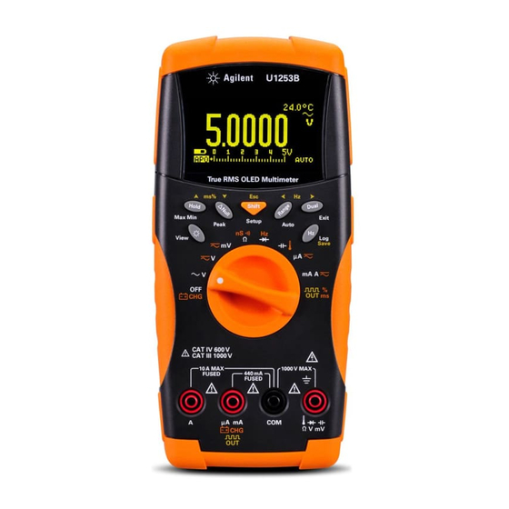
Agilent U1253B True
RMS OLED Multimeter
User’s and Service Guide
Agilent Technologies
Related Manuals for Agilent Technologies U1253B
Summary of Contents for Agilent Technologies U1253B
-
Page 1
Agilent U1253B True RMS OLED Multimeter User’s and Service Guide Agilent Technologies… -
Page 2: Trademark Acknowledgements
Notices Warranty Safety Notices ® Agilent Technologies, Inc. , 2009-2010 No part of this manual may be reproduced in The material contained in this docu- any form or by any means (including elec- ment is provided “as is,” and is sub-…
-
Page 3: Safety Symbols
In position of a bi-stable push control CAT III Equipotentiality Category III 1000 V overvoltage protection 1000 V Equipment protected throughout by CAT IV double insulation or reinforced Category IV 600 V overvoltage protection 600 V insulation U1253B User’s and Service Guide…
-
Page 4: General Safety Information
Agilent Technologies assumes no liability for the customer’s failure to comply with these requirements. U1253B User’s and Service Guide…
-
Page 5
Remove power and do not use the product until safe operation can be verified by service-trained personnel. If necessary, return the product to the nearest Agilent Technologies Sales and Service office for service and repair to ensure the safety features are maintained. -
Page 6
• Never measure voltage when current measurement is selected. • Use only the recommended rechargeable battery. Ensure proper insertion of battery in the multimeter, and follow the correct polarity. • Disconnect test leads from all the terminals during battery charging. U1253B User’s and Service Guide… -
Page 7: Environmental Conditions
Altitude Up to 2000 m Pollution degree Pollution Degree 2 The U1253B True RMS OLED Multimeter complies with the following C A U T I O N safety and EMC requirements. • IEC 61010-1:2001/EN61010-1:2001 (2nd Edition) • Canada: CAN/CSA-C22.2 No. 61010-1-04 •…
-
Page 8
Cet appareil ISM est confomre a la this electrical/electronic product in norme NMB-001 du Canada. domestic household waste. The CSA mark is a registered trademark of the Canadian Standards Association. VIII U1253B User’s and Service Guide… -
Page 9
Technologies, or visit: www.agilent.com/environment/product for more information. Agilent Technologies, through Rechargeable Battery Recycling Corporation (RBRC), offers free and convenient battery recycling options in the U.S. and Canada. Contact RBRC at 877-2-RECYCLE (877.273.2925) or online at: http://www.call2recycle.org/ for the nearest recycling location. -
Page 10: In This Guide
In This Guide… Getting Started Tutorial This chapter contains a brief description of the U1253B true RMS OLED multimeter front panel, rotary switch, keypad, display, terminals, and rear panel. Making Measurements This chapter contains detailed information on how to take measurements using the U1253B true RMS OLED multimeter.
-
Page 11
The Declaration of Conformity (DoC) for this instrument is available on the Web site. You can search the DoC by its product model or description. http://regulations.corporate.agilent.com/DoC/search.htm If you are unable to search for the respective DoC, please contact your N O T E local Agilent representative. U1253B User’s and Service Guide… -
Page 12
U1253B User’s and Service Guide… -
Page 13: Table Of Contents
Contents Getting Started Tutorial Introducing the Agilent U1253B True RMS OLED Multimeter Adjusting the tilt-stand The front panel at a glance The rotary switch at a glance The keypad at a glance The display at a glance Selecting display with the Shift button…
-
Page 14
Default Factory Settings and Available Setting Options Setting Data Hold/Refresh Hold mode Setting data logging mode Setting dB measurement Setting reference impedance for dBm measurement Setting thermocouple types Setting temperature unit Setting percentage scale readout U1253B User’s and Service Guide… -
Page 15
Smooth refresh rate Returning to default factory settings Setting the battery type Setting the DC filter Maintenance Introduction General maintenance Battery replacement Charging battery Fuse checking procedure Fuse replacement Troubleshooting Performance Tests and Calibration Calibration Overview U1253B User’s and Service Guide… -
Page 16
Resetting the security code to factory default Adjustment Considerations Valid adjustment reference input values Calibration from Front Panel Calibration process Calibration procedures Calibration count Calibration error codes Specifications DC Specifications AC Specifications AC+DC Specifications Temperature and Capacitance Specifications U1253B User’s and Service Guide… -
Page 17
Frequency sensitivity during voltage measurement Frequency sensitivity during current measurement Duty cycle and pulse width Frequency counter specifications Peak hold (capturing changes) Square wave output Operating Specifications General Specifications Measurement Category Measurement category definition U1253B User’s and Service Guide XVII… -
Page 18
XVIII U1253B User’s and Service Guide… -
Page 19
Manual (hand) logging mode operation Figure 3-9 Full log Figure 3-10 Interval (time) logging mode operation Figure 3-11 Log review mode operation Figure 3-12 Frequency adjustment for square wave output Figure 3-13 Duty cycle adjustment for square wave output U1253B User’s and Service Guide… -
Page 20
Refresh rate for primary display readings Figure 4-30 Resetting to default factory settings Figure 4-31 Battery type selection Figure 4-32 DC filter Figure 5-1 Rear panel of the Agilent U1253B True RMS OLED Multimeter Figure 5-2 Self-testing time display U1253B User’s and Service Guide… -
Page 21
Current terminal error message Figure 6-3 Charge terminal error message Figure 6-4 Unsecuring the instrument for calibration Figure 6-5 Changing the calibration security code Figure 6-6 Resetting security code to factory default Figure 6-7 Typical calibration process flow U1253B User’s and Service Guide… -
Page 22
XXII U1253B User’s and Service Guide… -
Page 23
Table 5-1 Battery voltage and corresponding percentage of charg- es in standby and charging modes Table 5-2 Error messages Table 5-3 U1253B measurement readings for fuse checking Table 5-4 Fuse specifications Table 5-5 Basic troubleshooting procedures Table 6-1 Recommended test equipment… -
Page 24
Accuracy for pulse width Table 7-13 Frequency counter (divide 1) specifications Table 7-14 Frequency counter (divide 100) specifications Table 7-15 Peak hold specification Table 7-16 Square wave output specifications Table 7-17 Measurement rate Table 7-18 Input Impedance XXIV U1253B User’s and Service Guide… -
Page 25
Selecting display with the Hz button The terminals at a glance The rear panel at a glance This chapter contains a brief description of the U1253B true RMS OLED multimeter front panel, rotary switch, keypad, display, terminals, and rear panel. -
Page 26: Getting Started Tutorial
Getting Started Tutorial Introducing the Agilent U1253B True RMS OLED Multimeter The key features of the true RMS OLED multimeter are: • DC, AC, and AC+DC voltage and current measurements. • True RMS measurement for both AC voltage and current.
-
Page 27: Adjusting The Tilt-Stand
Adjusting the tilt-stand To adjust the multimeter to a 60° standing position, pull the tilt- stand outward to its maximum reach. IR-USB cable To PC (host) ° Tilt-stand at 60 Figure 1-1 Tilt-stand at 60° U1253B User’s and Service Guide…
-
Page 28
Then flip the stand over so that its inner surface is facing the rear. Now, press the stand down into its hinge. Follow the step- by- step pictorial instructions below. U1253B User’s and Service Guide… -
Page 29: Figure 1-3 Tilt-Stand At Hanging Position
Getting Started Tutorial Figure 1-3 Tilt-stand at hanging position U1253B User’s and Service Guide…
-
Page 30: The Front Panel At A Glance
Getting Started Tutorial The front panel at a glance Display Keypad Rotary switch Terminals U1253B User’s and Service Guide…
-
Page 31: The Rotary Switch At A Glance
Frequency counter or diode Capacitance or temperature DC μA, AC μA, or AC+DC μA DC mA, DC A, AC mA, AC A, AC+DC mA, or AC+DC A Square wave output, duty cycle, or pulse width output U1253B User’s and Service Guide…
-
Page 32: The Keypad At A Glance
Pressing a key displays a related symbol and emits a sound on the beeper. Turning the rotary switch to another position resets the current operation of the key. Figure 1- 4 shows the keypad of the U1253B. Figure 1-4 U1253B keypad U1253B User’s and Service Guide…
-
Page 33: Table 1-2 Keypad Descriptions And Functions
• Press for more than 1 second to exit this mode. scrolls through the available enters the Auto Range mode. measurement ranges (except when the rotary switch is at the position) U1253B User’s and Service Guide…
-
Page 34
For pulse width and duty cycle measurements, press to switch between positive and negative edge trigger. When the multimeter is in Peak or Dynamic Recording mode, press to restart the 1 ms Peak Hold or Dynamic Recording mode. U1253B User’s and Service Guide… -
Page 35: The Display At A Glance
• Capacitor is charging (during capacitance measurement) • Negative slope for pulse width (ms) and duty cycle (%) measurements • Capacitor is discharging (during capacitance measurement) Low battery indication (alternating between these two symbols) Auto Power-Off enabled Refresh (auto) Hold U1253B User’s and Service Guide…
-
Page 36: Table 1-4 Primary Display Annunciators
Hazardous Voltage annunciator for measuring voltage ≥ 30 V or Overload The primary display annunciators are described below. Table 1-4 Primary display annunciators OLED Annunciator Description Auto range AC+DC Polarity, digits, and decimal points for primary display U1253B User’s and Service Guide…
-
Page 37
Capacitance units: nF, μF, mF Celsius temperature unit Fahrenheit temperature unit Duty cycle measurement Pulse width unit Percentage scale readout based on DC 0 mA to 20 mA Percentage scale readout based on DC 4 mA to 20 mA U1253B User’s and Service Guide… -
Page 38: Table 1-5 Secondary Display Annunciators
Decibel unit relative to 1 mW Decibel unit relative to 1 V Frequency units: Hz, kHz, MHz Resistance units: Ω, kΩ, MΩ Voltage units: mV, V Current units: μA, mA, A Conductance unit: nS Capacitance units: nF, μF, mF U1253B User’s and Service Guide…
-
Page 39
• Another example is when 4 mA to 20 mA % scale ( ) or 0 mA to 20 mA % scale ( ) is displayed on the primary display, the bar graph represents the current value and not the percentage value. U1253B User’s and Service Guide… -
Page 40: Table 1-6 Analog Bar Range And Counts
2000 or 400 counts depending on the range indicated on the peak bar graph. See the following table. Table 1-6 Analog bar range and counts Range Counts/segments Used for the function V, A, Ω, nS, Diode 2000 V, A, Capacitance U1253B User’s and Service Guide…
-
Page 41: Selecting Display With The Shift Button
(AC+DC voltage) AC+DC V DC mV AC mV (AC+DC voltage) AC+DC mV DC mV AC mV (AC+DC voltage) AC+DC mV Ω Ω (Audible) AC+DC mV Diode Capacitance Temperature DC μA AC μA (AC+DC current) AC+DC μA U1253B User’s and Service Guide…
-
Page 42
(With the positive probe inserted into the A terminal) AC+DC A Duty cycle (%) Pulse width (ms) Depends on the relevant setting in the Setup mode. Press for more than 1 second to return to AC V measurement only. U1253B User’s and Service Guide… -
Page 43: Selecting Display With The Dual Button
Hz (DC coupling) dBm or dBV DC mV (Default is DC voltage) DC mV AC mV AC mV Hz (AC coupling) dBm or dBV AC mV (Press to select AC voltage) AC mV DC mV U1253B User’s and Service Guide…
-
Page 44
AC current) AC+DC mA Hz (AC coupling) AC+DC mA AC mA (Press twice to select AC+DC current) AC+DC mA DC mA DC A Hz (DC coupling) DC A AC A DC current) Default is U1253B User’s and Service Guide… -
Page 45
ºC (ºF) selected in the Setup, there will be no secondary display. Ambient temperature in ºC or ºF is displayed in upper-right corner. Select 0 ºC compensation by pressing Depends the relevant setting in Setup mode. U1253B User’s and Service Guide… -
Page 46: Selecting Display With The Hz Button
(Default is DC voltage) Duty cycle (%) Frequency (Hz) Pulse width (ms) AC+DC V (Press twice to select AC+DC voltage) Duty cycle (%) Frequency (Hz) Pulse width (ms) DC mV (Default is DC voltage) Duty cycle (%) U1253B User’s and Service Guide…
-
Page 47
Duty cycle (%) Frequency (Hz) Pulse width (ms) AC mA or A (Press to select AC current) Duty cycle (%) Frequency (Hz) Pulse width (ms) AC+DC mA (Press twice to select AC+DC current) Duty cycle (%) U1253B User’s and Service Guide… -
Page 48
Table 1-9 Selecting display with the Hz button (continued) Rotary switch position (Function) Primary display Secondary display Frequency (Hz) Pulse width (ms) Hz (Frequency counter) Pulse width (ms) Frequency (Hz) (Only applicable for Divide-1 input) Duty cycle (%) U1253B User’s and Service Guide… -
Page 49: The Terminals At A Glance
Getting Started Tutorial The terminals at a glance To avoid damaging this device, do not exceed the rated input limit. C A U T I O N Figure 1-5 Connector terminals U1253B User’s and Service Guide…
-
Page 50: Table 1-10 Terminal Connections For Different Measurement
Table 1-10 Terminal connections for different measurement functions Rotary switch position Input terminals Overload protection 1000 Vrms 1000 Vrms for short circuit <0.3 A 440 mA/1000 V, 30 kA μA.mA fast-acting fuse 11 A/1000V, 30kA fast-acting fuse 440 mA/1000 V fast-acting fuse U1253B User’s and Service Guide…
-
Page 51: The Rear Panel At A Glance
Getting Started Tutorial The rear panel at a glance IR communication port Test probe holders Battery access cover Figure 1-6 Rear panel of U1253B U1253B User’s and Service Guide…
-
Page 52
Getting Started Tutorial U1253B User’s and Service Guide… -
Page 53: Making Measurements
Measuring Resistance, Conductance, and Testing Continuity Testing Diodes Measuring Capacitance Measuring Temperature Alerts and Warning During Measurement Voltage alert Input warning Charge terminal alert This chapter contains detailed information on how to take measurements using the U1253B true RMS OLED multimeter. Agilent Technologies…
-
Page 54: Measuring Voltage
Making Measurements Measuring Voltage The U1253B true RMS OLED multimeter returns an accurate RMS reading not only for sine waves, but also other AC signals such as square, triangle, and staircase waves. For AC with DC offset, use AC+DC measurement by selecting with the rotary switch.
-
Page 55: Figure 2-1 Measuring Ac Voltage
Making Measurements Figure 2-1 Measuring AC voltage U1253B User’s and Service Guide…
-
Page 56: Measuring Dc Voltage
See “Selecting display with the Dual button” on page 19 for a list of dual measurements available. Press and hold more than 1 second to exit dual display mode. Figure 2-2 Measuring DC voltage U1253B User’s and Service Guide…
-
Page 57: Measuring Current
• for mA measurement, set the rotary switch to , and connect the positive test lead to μA.mA. • for A (ampere) measurement, set the rotary switch to and connect the positive test lead to A. U1253B User’s and Service Guide…
-
Page 58: Figure 2-3 Measuring Μa And Ma Current
Making Measurements Figure 2-3 Measuring μA and mA current U1253B User’s and Service Guide…
-
Page 59: Percentage Scale Of 4 Ma To 20 Ma
The percentage scale for 4 mA to 20 mA or 0 mA to 20 mA is calculated using its corresponding DC mA measurement. The U1253B will automatically optimize the best resolution according to the table below. 4 Press to change the measurement range.
-
Page 60: Figure 2-4 Measurement Scale Of 4 Ma To 20 Ma
Making Measurements Figure 2-4 Measurement scale of 4 mA to 20 mA U1253B User’s and Service Guide…
-
Page 61: A (Ampere) Measurement
A (red) and COM (black) respectively (see Figure 2- 5). When the red test lead is plugged into the A (red) terminal, the multimeter is automatically set to measurement. Figure 2-5 A (ampere) current measurement U1253B User’s and Service Guide…
-
Page 62: Frequency Counter
This accommodates a higher frequency range of up to 20 MHz. 6 The signal is out of the U1253B frequency measurement range of 20 MHz if the reading is still unstable after Step Press…
-
Page 63: Figure 2-6 Measuring Frequency
Making Measurements Press Range Figure 2-6 Measuring frequency U1253B User’s and Service Guide…
-
Page 64: Measuring Resistance, Conductance, And Testing Continuity
The Smart Ω is applicable for 500 Ω, 5 kΩ, 50 kΩ, and 500 kΩ resistance range only. The maximum correctable offset/bias voltage is ±1.9 V for 500 Ω range and ±0.35 V for 5 kΩ, 50 kΩ, and 500 kΩ range. U1253B User’s and Service Guide…
-
Page 65: Figure 2-7 Type Of Display When Smart
Smart Ω • Press feature. The measurement time increases when Smart Ω is enabled. N O T E Bias Display Press Press Leak Display Figure 2-7 Type of display when Smart Ω is enabled U1253B User’s and Service Guide…
-
Page 66: Figure 2-8 Measuring Resistance
Making Measurements Figure 2-8 Measuring resistance U1253B User’s and Service Guide…
-
Page 67: Figure 2-9 Resistance, Audible Continuity, And Conductance
Making Measurements Resistance Press Shift Audible continuity Press Shift Press Shift Conductance Figure 2-9 Resistance, audible continuity, and conductance tests U1253B User’s and Service Guide…
-
Page 68: Table 2-2 Audible Continuity Measurement Range
< 10 MΩ When testing continuity, you can choose to test either short continuity or N O T E open continuity. • By default, the multimeter is set to short continuity. • Press to select open continuity. U1253B User’s and Service Guide…
-
Page 69: Figure 2-10 Short Continuity And Open Continuity Test
100 GΩ (refer to Figure 2- 11 on page 46 for probe connection). As high- resistance readings are susceptible to noise, you can capture average readings using the Dynamic Recording mode. Figure 3- 1 on page 77. U1253B User’s and Service Guide…
-
Page 70: Figure 2-11 Conductance Measurement
Making Measurements Figure 2-11 Conductance measurement U1253B User’s and Service Guide…
-
Page 71: Testing Diodes
• A diode is considered shorted if the multimeter displays approximately 0 V in both forward and reverse bias modes, and the multimeter beeps continuously. • A diode is considered open if the multimeter displays “OL” in both forward and reverse bias modes. U1253B User’s and Service Guide…
-
Page 72: Figure 2-12 Measuring The Forward Bias Of A Diode
Making Measurements Figure 2-12 Measuring the forward bias of a diode U1253B User’s and Service Guide…
-
Page 73: Figure 2-13 Measuring The Reverse Bias Of A Diode
Making Measurements Figure 2-13 Measuring the reverse bias of a diode U1253B User’s and Service Guide…
-
Page 74: Measuring Capacitance
To confirm that a capacitor has fully discharged, use the DC voltage function. The U1253B true RMS OLED multimeter calculates capacitance by charging a capacitor with a known current for a period of time, and then measuring the voltage Measuring tips: •…
-
Page 75: Measuring Temperature
• For quick measurement, use the 0 °C compensation to view the temperature variation of the thermocouple sensor. The 0 °C compensation assists you in measuring relative temperature immediately. U1253B User’s and Service Guide…
-
Page 76
3 After a constant reading is obtained, press to set the reading as the relative reference temperature. 4 Touch the surface to be measured with the thermocouple probe. 5 Read the display for the relative temperature. U1253B User’s and Service Guide… -
Page 77: Figure 2-14 Surface Temperature Measurement
Making Measurements Press Dual Figure 2-14 Surface temperature measurement U1253B User’s and Service Guide…
-
Page 78: Alerts And Warning During Measurement
30 V in all three DC V, AC V and AC+DC V measurement modes. For a manually selected measurement range, when the measured value is outside the range, the display will indicate OL. U1253B User’s and Service Guide…
-
Page 79: Input Warning
A warning message Error ON A INPUT will be displayed until the test lead is removed from the A input terminal. See Figure 2- Figure 2-15 Input terminal warning U1253B User’s and Service Guide…
-
Page 80: Charge Terminal Alert
A warning message Error ON mA INPUT will be displayed until the lead is removed from the input terminal. See Figure 2- Figure 2-16 Charge terminal alert U1253B User’s and Service Guide…
-
Page 81
Null (Relative) Decibel Display 1 ms Peak Hold Data Logging Manual logging Interval logging Reviewing logged data Square wave Output Remote Communication This chapter contains detailed information on functions and features available in the U1253B true RMS OLED multimeter. Agilent Technologies… -
Page 82: Functions And Features
• The average value is the true average of all measured values taken in the Dynamic recording mode. If an overload is recorded, the averaging function will stop and the average value becomes “OL” (overload). Auto Power Off is disabled in Dynamic Recording mode. U1253B User’s and Service Guide…
-
Page 83: Figure 3-1 Dynamic Recording Mode Operation
Max Min Press Max Min for > 1 sec. Press Max Min Press Max Min for > 1 sec. Press Max Min Press Max Min for > 1 sec. Figure 3-1 Dynamic recording mode operation U1253B User’s and Service Guide…
-
Page 84: Data Hold (Trigger Hold)
3 While in the Data Hold mode, you may press switch between DC, AC, and AC+DC measurements. 4 Press and hold for more than 1 second to quit this mode. U1253B User’s and Service Guide…
-
Page 85: Figure 3-2 Data Hold Mode Operation
Functions and Features Press Hold Press Shift Press Press Reading Reading Hold Hold (“T” flashes) (“T” flashes) Updated Updated Figure 3-2 Data hold mode operation U1253B User’s and Service Guide…
-
Page 86: Refresh Hold
4 While in the Refresh Hold mode, you may press switch between DC, AC, and AC+DC measurements. 5 Press again to disable this function. You may also press for more than 1 second to quit this function. U1253B User’s and Service Guide…
-
Page 87: Figure 3-3 Refresh Hold Mode Operation
• For resistance and diode measurements, the held value will not be updated if the reading is “OL” (open state). • For all types of measurement, the held value will not be updated until the reading has reached a stable state. U1253B User’s and Service Guide…
-
Page 88: Null (Relative)
Use the Null function to zero-adjust the display. • In DC voltage measurement mode, thermal effects will influence the accuracy. Short the test leads and press once the displayed value is stable to zero-adjust the display. U1253B User’s and Service Guide…
-
Page 89: Figure 3-4 Null (Relative) Mode Operation
Functions and Features Press Null Press Null while O’BASE is being displayed to exit this mode (or press Dual for more than Auto-return Press 1 second) after 3 seconds Null Figure 3-4 Null (relative) mode operation U1253B User’s and Service Guide…
-
Page 90: Decibel Display
The voltage measurement is indicated on the secondary display. 2 Press for more than 1 second to exit this mode. Depends on configuration in Setup mode. U1253B User’s and Service Guide…
-
Page 91: Figure 3-5 Dbm Display Mode Operation
Functions and Features Press Dual Press Dual for > 1 sec. Press Press Dual Dual Figure 3-5 dBm display mode operation U1253B User’s and Service Guide…
-
Page 92: Figure 3-6 Dbv Display Mode Operation
Functions and Features Press Dual Press Dual for > 1 sec. Press Press Dual Dual Figure 3-6 dBV display mode operation U1253B User’s and Service Guide…
-
Page 93: Ms Peak Hold
• If you need to restart peak recording without changing the range, press 3 Press for more than 1 second to exit this mode. 4 In the measurement example shown in Figure 3- 7 page 70, the crest factor will be 2.2669/1.6032 = 1.414. U1253B User’s and Service Guide…
-
Page 94: Figure 3-7 1 Ms Peak Hold Mode Operation
Start to capture Start to capture to reset Press Max Min Press Press Range Range (Note: pressing Range when in Negative P-HOLD– will change the display into Positive P-HOLD+.) Figure 3-7 1 ms peak hold mode operation U1253B User’s and Service Guide…
-
Page 95: Data Logging
3 seconds. 2 Press and hold again for the next value that you would like to save into the memory. U1253B User’s and Service Guide…
-
Page 96: Figure 3-8 Manual (Hand) Logging Mode Operation
N O T E the 100 entries are all occupied, the logging index will indicate “Full”, as shown in Figure 3-9. Press Log for > 1 sec. Auto-return after 3 seconds Figure 3-9 Full log U1253B User’s and Service Guide…
-
Page 97: Interval Logging
When interval (time) logging is running, all keypad operations are disabled, N O T E except for Log, which, when pressed for longer than 1 second, will exit this mode. Furthermore, Auto Power Off is disabled during interval logging. U1253B User’s and Service Guide…
-
Page 98: Figure 3-10 Interval (Time) Logging Mode Operation
Press Log for > 1 sec. After first interval Press Log for > 1 sec. Press Log for > 1 sec. Stop logging After last interval Last interval Figure 3-10 Interval (time) logging mode operation U1253B User’s and Service Guide…
-
Page 99: Reviewing Logged Data
4 Press for more than 1 second at the respective Log Review mode to clear logged data. 5 Press for more than 1 second to stop logging and exit this mode. U1253B User’s and Service Guide…
-
Page 100: Figure 3-11 Log Review Mode Operation
Press Press Press Press Press Press Press Press Log for > 1 sec. Press Log for > 1 sec. to clear all manual logs to clear all interval logs Figure 3-11 Log review mode operation U1253B User’s and Service Guide…
-
Page 101: Square Wave Output
Functions and Features Square wave Output The U1253B true RMS OLED multimeter’s square wave output can be used to generate a PWM (pulse width modulation) output or provide a synchronous clock source (baud rate generator). You can also use this function to check and calibrate flow- meter…
-
Page 102: Figure 3-12 Frequency Adjustment For Square Wave Output
Functions and Features Press Press Press Press Figure 3-12 Frequency adjustment for square wave output U1253B User’s and Service Guide…
-
Page 103: Figure 3-13 Duty Cycle Adjustment For Square Wave Output
256 steps, with each step equivalent to 0.390625%. The best resolution the display can offer is 0.001%. Press Press Press Press Press Press Figure 3-13 Duty cycle adjustment for square wave output U1253B User’s and Service Guide…
-
Page 104: Figure 3-14 Pulse Width Adjustment For Square Wave Output
1/(256 × frequency). The displayed pulse width will be automatically adjusted to 5 digits (ranging from 9.9999 to 9999.9 ms). Press Press Press Press Press Press Figure 3-14 Pulse width adjustment for square wave output U1253B User’s and Service Guide…
-
Page 105: Remote Communication
Agilent Web site. For details on performing PC- multimeter remote communication, click on Help after launching the Agilent GUI Data Logger software. Connect to PC Figure 3-15 Cable connection for remote communication U1253B User’s and Service Guide…
-
Page 106
Functions and Features U1253B User’s and Service Guide… -
Page 107
Smooth refresh rate Returning to default factory settings Setting the battery type Setting the DC filter This chapter describes how to change the default factory settings of the U1253B true RMS OLED multimeter and other available setting options. Agilent Technologies… -
Page 108: Changing The Default Settings
Press to exit EDIT mode without saving the changes. iv Press to save the changes you have made and exit the EDIT mode. 4 Press for more than 1 second to exit Setup mode. U1253B User’s and Service Guide…
-
Page 109: Default Factory Settings And Available Setting Options
• Available options: dBm, dBV, or OFF. • Select OFF to disable this function for normal operation. 50 Ω dBm-R Reference impedance value for dBm measurement. Select a value within the range of 1 Ω to 9999 Ω. U1253B User’s and Service Guide…
-
Page 110
• To disable this function, set all digits to zero (“OFF” will be indicated). BACKLIT HIGH Default power-on backlight brightness level. Available options: HIGH, MEDIUM, or LOW. MELODY FACTORY Power-on melody. Available options: FACTORY, USER or OFF. GREETING FACTORY Power-on greeting. Available options: FACTORY, USER or OFF. U1253B User’s and Service Guide… -
Page 111
BATTERY 7.2 V Battery type used for the multimeter. Available options: 7.2 V or 8.4 V. DC FILTER Filter for DC voltage or DC current measurement. Available options: OFF or U1253B User’s and Service Guide… -
Page 112: Figure 4-1 Setup Menu Screens
Changing the Default Settings Press Press Press Press Press Press Press Press Press Press Press Press Press Press Press Press Press Press Press Press Figure 4-1 Setup menu screens U1253B User’s and Service Guide…
-
Page 113: Setting Data Hold/Refresh Hold Mode
RHOLD to “OFF” (enable Data Hold) Press to edit the value you want to edit Press Hz to save and exit or press Esc to exit without saving Figure 4-2 Data Hold/Refresh Hold setup U1253B User’s and Service Guide…
-
Page 114: Setting Data Logging Mode
Esc to exit without saving Figure 4-3 Data logging setup 2 For interval (time) data logging, set the LOG TIME within the range of 0001 second to 9999 seconds to specify the data logging interval. U1253B User’s and Service Guide…
-
Page 115: Figure 4-4 Log Time Setup For Interval (Time) Logging
Press to go to the digit you want to edit Press Hz to save and exit or press Esc to exit without saving Figure 4-4 Log time setup for interval (time) logging U1253B User’s and Service Guide…
-
Page 116: Setting Db Measurement
“dBm- R” menu item. Press Hz to edit Press to switch between dBm and dBV Press Hz to save and exit or press Esc to exit without saving Figure 4-5 Decibel measurement setup U1253B User’s and Service Guide…
-
Page 117: Setting Reference Impedance For Dbm Measurement
Press to go to the digit you want to edit Press Hz to save and exit or press Esc to exit without saving Figure 4-6 Setting up the reference impedance for dBm unit U1253B User’s and Service Guide…
-
Page 118: Setting Thermocouple Types
1 Celsius only: °C single display. 2 Celsius/Fahrenheit: °C/°F dual display; °C on primary, and °F on secondary. 3 Fahrenheit only: °F single display. 4 Fahrenheit/Celsius: °F/°C dual display; °F on primary, and °C on secondary. U1253B User’s and Service Guide…
-
Page 119: Figure 4-8 Temperature Unit Setup
Press unlock Press Hz to edit Press to change the unit Press to change the unit Press Hz to save and exit or press Esc to exit without saving Figure 4-8 Temperature unit setup U1253B User’s and Service Guide…
-
Page 120: Setting Percentage Scale Readout
To disable this function, set this to “OFF”. Press Hz to edit Press to configure Press Hz to save and exit or press Esc to exit without saving Figure 4-9 Setting up percentage scale readout U1253B User’s and Service Guide…
-
Page 121: Sound Setting For Continuity Test
Press Hz to edit Press to configure Press Hz to save and exit or press Esc to exit without saving Figure 4-10 Choosing the sound used in continuity test U1253B User’s and Service Guide…
-
Page 122: Setting Minimum Measurable Frequency
1 Hz. Press Hz to edit Press to choose the value Press to choose the value Press Hz to save and exit or press Esc to exit without saving Figure 4-11 Minimum frequency setup U1253B User’s and Service Guide…
-
Page 123: Setting Beep Frequency
Press to choose the value Press to choose the value Press to choose the value Press Hz to save and exit or press Esc to exit without saving Figure 4-12 Beep frequency setup U1253B User’s and Service Guide…
-
Page 124: Setting Auto Power Off Mode
• To disable APO, select OFF. When APO is disable, the annunciator will be turned off. The multimeter will remain on until you manually turn the rotary switch to the OFF position. U1253B User’s and Service Guide…
-
Page 125: Figure 4-13 Automatic Power Saving Setup
Set all digits to ZERO to set APO to “OFF” Press to go to the digit you want to edit Press Hz to save and exit or press Esc to exit without saving Figure 4-13 Automatic power saving setup U1253B User’s and Service Guide…
-
Page 126: Setting Power-On Backlight Brightness Level
Press Hz to save and exit or press Esc to exit without saving Figure 4-14 Power-on backlight setup While using the multimeter, you may adjust the brightness at any time by pressing the button. U1253B User’s and Service Guide…
-
Page 127: Setting The Power-On Melody
The melody that is played when the multimeter turns on can be set to FACTORY, USER or turned OFF. Press Hz to edit Press to configure Press Hz to save and exit or press Esc to exit without saving Figure 4-15 Power-on melody setup U1253B User’s and Service Guide…
-
Page 128: Setting The Power-On Greeting Screen
FACTORY, USER or turned OFF. Press Hz to edit Press to configure Press Hz to save and exit or press Esc to exit without saving Figure 4-16 Power-on greeting setup U1253B User’s and Service Guide…
-
Page 129: Setting Baud Rate
Press Hz to edit Press to choose the value Press to choose the value Press Hz to save and exit or press Esc to exit without saving Figure 4-17 Baud rate setup for remote control U1253B User’s and Service Guide…
-
Page 130: Setting Parity Check
NONE, ODD, or EVEN. Press Hz to edit Press to configure Press Hz to save and exit or press Esc to exit without saving Figure 4-18 Parity check setup for remote control U1253B User’s and Service Guide…
-
Page 131: Setting Data Bits
The number of stop bit is always 1, and this cannot be changed. Press Hz to edit Press to switch between 7 and 8 Press Hz to save and exit or press Esc to exit without saving Figure 4-19 Data bits setup for remote control U1253B User’s and Service Guide…
-
Page 132: Setting Echo Mode
Press Hz to edit Press to switch between OFF and ON Press Hz to save and exit or press Esc to exit without saving Figure 4-20 Echo mode setup for remote control U1253B User’s and Service Guide…
-
Page 133: Setting Print Mode
Press Hz to edit Press to switch between OFF and ON Press Hz to save and exit or press Esc to exit without saving Figure 4-21 Print mode setup for remote control U1253B User’s and Service Guide…
-
Page 134: Revision
Changing the Default Settings Revision The revision number of the firmware will be indicated. Figure 4-22 Revision number Serial number The last 8 digits of the serial number will be indicated. Figure 4-23 Serial number U1253B User’s and Service Guide…
-
Page 135: Voltage Alert
Press to edit the value Press to go to the digit you want to edit Press Hz to save and exit or press Esc to exit without saving Figure 4-24 Voltage alert setup U1253B User’s and Service Guide…
-
Page 136: M-Initial
As example, when you turn the rotary switch to the position, the initial measurement function is diode measurement, according to the default factory setting. In order to choose the frequency counter function, you have to press the button. U1253B User’s and Service Guide…
-
Page 137: Figure 4-25 Setting Initial Measurement Functions
In the INIT pages, you may define your preferred initial measurement functions. Please refer to Figure 4- Press to navigate between the two INIT pages. Press to choose which initial function you want to change. U1253B User’s and Service Guide…
-
Page 138: Figure 4-26 Navigating Between The Initial Functions Pages
Edit F1 initial range and F5 initial function Figure 4-27 Editing initial measurement function/range As another example, Figure 4- 28 below illustrates that: • The F6 default function is changed from capacitance measurement to temperature measurement; U1253B User’s and Service Guide…
-
Page 139: Figure 4-28 Editing Initial Measurement Function/Range And Initial Output Values
EDIT mode. changes. Press If you reset the multimeter to its default factory settings (see “Returning to default factory settings” on page 117), your settings for M- INITIAL will also revert to the factory defaults. U1253B User’s and Service Guide…
-
Page 140: Smooth Refresh Rate
(including duty cycle and pulse width measurements). The default is NORMAL. Press Hz to edit Press to configure Press Hz to save and exit or press Esc to exit without saving Figure 4-29 Refresh rate for primary display readings U1253B User’s and Service Guide…
-
Page 141: Returning To Default Factory Settings
1 second to reset to default factory settings (all except the temperature setting). • The Reset menu item automatically reverts to menu page m1 after a reset has taken place. Figure 4-30 Resetting to default factory settings U1253B User’s and Service Guide…
-
Page 142: Setting The Battery Type
7.2 V or 8.4 V. Press Hz to edit Press to switch between 7.2 V and 8.4 V Press Hz to save and exit or press Esc to exit without saving Figure 4-31 Battery type selection U1253B User’s and Service Guide…
-
Page 143: Setting The Dc Filter
• When DC filter is enabled, the measurement speed may decrease N O T E during DC voltage measurement. • During AC or Hz measurement (on primary or secondary display), DC filter will be automatically disabled. U1253B User’s and Service Guide…
-
Page 144
Changing the Default Settings U1253B User’s and Service Guide… -
Page 145: Maintenance
Agilent U1253B True RMS OLED Multimeter User’s and Service Guide Maintenance Introduction General maintenance Battery replacement Charging battery Fuse checking procedure Fuse replacement Troubleshooting This chapter will help you troubleshoot a malfunctioning U1253B true RMS OLED multimeter. Agilent Technologies…
-
Page 146: Introduction
3 Wipe the case with a damp cloth and mild detergent — do not use abrasives or solvents. Wipe the contacts in each terminal with a clean cotton swab moistened with alcohol. U1253B User’s and Service Guide…
-
Page 147: Battery Replacement
Alternatively you may also use a 9 V Alkaline battery (ANSI/NEDA 1604A or IEC 6LR61) or a 9 V Carbon- zinc battery (ANSI/NEDA 1604D or IEC6F22) to power the U1253B. To ensure that the multimeter performs as specified, it is recommended that you replace the battery as soon as the low- battery indicator is displayed flashing.
-
Page 148: Figure 5-1 Rear Panel Of The Agilent U1253B True Rms Oled
1 On the rear panel, turn the screw on the battery cover counterclockwise from the LOCK position to OPEN. Figure 5-1 Rear panel of the Agilent U1253B True RMS OLED Multime- 2 Slide the battery cover down. 3 Lift the battery cover up.
-
Page 149: Charging Battery
DC voltage of 24 V is applied to the charging terminals. Follow the procedures below to charge the battery: 1 Remove the test leads from the multimeter. 2 Turn the rotary switch to 3 Plug the DC adapter into a power outlet. U1253B User’s and Service Guide…
-
Page 150: Figure 5-2 Self-Testing Time Display
Table 5-1 Battery voltage and corresponding percentage of charges in standby and charging modes Condition Battery voltage Proportional percentage Trickle 6.0 V to 8.2 V 0% to 100% Being charged up 7.2 V to 10.0 V 0% to 100% U1253B User’s and Service Guide…
-
Page 151: Figure 5-3 Performing Self-Test
This self- test will take 3 minutes. Avoid pressing any of the push- buttons during the self- test. If there is any error, the multimeter will display error messages as shown in Table 5- 2 on page 128. Figure 5-3 Performing self-test U1253B User’s and Service Guide…
-
Page 152: Table 5-2 Error Messages
After replacing any wrong battery with the correct specified type of rechargeable battery, press to redo the self-test. Replace with a new battery if the CHARGE ERROR message is again displayed. U1253B User’s and Service Guide…
-
Page 153: Figure 5-4 Charging Mode
To avoid overcharging the battery, the charging may be stopped with an error message during the charging process. Figure 5-5 Fully charged and in the trickle state U1253B User’s and Service Guide…
-
Page 154
9 Remove the DC adapter when the battery has been fully charged. Do not turn the rotary switch before removing the adapter from the C A U T I O N terminals. U1253B User’s and Service Guide… -
Page 155: Figure 5-6 Battery Charging Procedures
Maintenance Press Shift or after time up to start charging Over limit level ERROR Charge error Battery can be charged Fully charged or time out Figure 5-6 Battery charging procedures U1253B User’s and Service Guide…
-
Page 156: Fuse Checking Procedure
Refer to Figure 5- 8 the respective positions of Fuse 1 and Fuse 2. 1 Set the rotary switch to 2 Connect the red test lead to the input terminal Figure 5-7 Fuse checking procedures U1253B User’s and Service Guide…
-
Page 157: Table 5-3 U1253B Measurement Readings For Fuse Checking
5 Observe the reading on the instrument’s display. Refer to Table 1 below for the possible readings that could appear). 6 Replace the fuse when OL is displayed. Table 5-3 U1253B measurement readings for fuse checking Fuse OK Replace fuse…
-
Page 158: Fuse Replacement
Table 5-4 Fuse specifications Fuse Agilent part number Rating Size Type 2110-1400 440 mA/1000 V 10 mm × 35 mm Fast blow fuse 2110-1402 11 A/1000 V 10 mm × 38 mm U1253B User’s and Service Guide…
-
Page 159: Figure 5-8 Fuse Replacement
Maintenance Fuse 2 Fuse 1 Figure 5-8 Fuse replacement U1253B User’s and Service Guide…
-
Page 160: Troubleshooting
• Check the baud rate, parity, data bit, and stop bit (default is 9600, None, 8, and 1) in the Setup mode. • Ensure that the required driver for IR-USB has been installed. U1253B User’s and Service Guide…
-
Page 161: Performance Tests And Calibration
Calibration from Front Panel This chapter contains the performance test and adjustment procedures. The performance test procedure verifies that the U1253B true RMS OLED multimeter is operating within its published specifications. The adjustment procedure ensures that the multimeter remains within its specifications until the next calibration.
-
Page 162: Calibration Overview
N O T E calibrating the instrument. Closed-case electronic calibration The U1253B true RMS OLED multimeter features closed- case electronic calibration. In other words, no internal electro- mechanical adjustment is required. This instrument calculates correction factors based on the input reference signals you feed into it during the calibration process.
-
Page 163: Other Recommendations For Calibration
Agilent recommends that readjustment should be performed during the calibration process for best performance. This will ensure that the U1253B true RMS OLED multimeter remains within its specifications. This calibration criterion provides the best long- term stability.
-
Page 164: Recommended Test Equipment
Table 6-1 Recommended test equipment Recommended Recommended accuracy Application equipment requirements DC voltage Fluke 5520A < 20% of U1253B accuracy spec DC current Fluke 5520A < 20% of U1253B accuracy spec Resistance Fluke 5520A < 20% of U1253B accuracy spec AC voltage Fluke 5520A <…
-
Page 165: Basic Operating Tests
Testing the display Press and hold the button while turning on the multimeter to view all the OLED pixels. Check for dead pixels. Figure 6-1 Displaying all OLED pixels U1253B User’s and Service Guide…
-
Page 166: Current Terminals Test
A terminal. Before conducting this test, make sure the beep function is not disabled in N O T E Setup. Figure 6-2 Current terminal error message U1253B User’s and Service Guide…
-
Page 167: Charge Terminals Alert Test
Figure 6-3 Charge terminal error message Before conducting this test, make sure the beep function is not disabled in N O T E Setup. U1253B User’s and Service Guide…
-
Page 168: Test Considerations
For DC voltage, DC current, and resistance gain verification measurements, you should ensure that the calibrator’s “0” output is correct. You will need to set the offset for each range of the measurement function being verified. U1253B User’s and Service Guide…
-
Page 169: Input Connections
Shielded twisted- pair Teflon interconnect cables of minimum length are recommended between the calibrator and the multimeter. Cable shields should be grounded to earth. This configuration is recommended for optimal noise and settling time performance during calibration. U1253B User’s and Service Guide…
-
Page 170: Performance Verification Tests
“Reference signals/values” column (one setting at a time, if more than one setting is listed). 3 Turn the rotary switch of the U1253B true RMS OLED multimeter to the function being tested, and choose the correct range, as specified in the table.
-
Page 171: Table 6-2 Performance Verification Tests
Turn the rotary switch to the position ± 1.75 mV Press to select DC V measurement 50 V 50 V ± 17.5 mV 500 V 500 V ± 200 mV 1000 V 1000 V ± 800 mV U1253B User’s and Service Guide…
-
Page 172
50 mV 50 mV Press to select DC mV measurement ± 175 μV 500 mV 500 mV ± 175 μV –500 mV 1000 mV 1000 mV ± 0.75 mV –1000 mV ± 0.75 mV U1253B User’s and Service Guide… -
Page 173
50 MΩ ± 505 kΩ 500 MΩ 450 MΩ ± 36.1 MΩ Press to select conductance (nS) 500 nS 50 nS ± 0.6 nS measurement Turn the rotary switch to the position Diode ± 1 mV U1253B User’s and Service Guide… -
Page 174
5000 μA, 1 kHz ± 37 μA 5000 μA, 20 kHz ± 39.5 μA ± 80 μA Turn the rotary switch to the 50 mA 50 mA position 440 mA 400 mA ± 0.65 mA U1253B User’s and Service Guide… -
Page 175
The additional error to be added for frequency > 20 kHz and signal input < 10% of range: 300 counts of LSD per kHz. An accuracy of 0.05% + 10 can be achieved by using the relative function to zero the thermal effect (short test leads) before measuring the signal. U1253B User’s and Service Guide… -
Page 176
[12] For signal frequencies greater than 1 kHz, an additional 0.1% error per kHz needs to be added to the accuracy. U1253B User’s and Service Guide… -
Page 177: Calibration Security
Performance Tests and Calibration Calibration Security A calibration security code is in place to prevent accidental or unauthorized adjustments to the U1253B true RMS OLED multimeter. When you first receive your instrument, it is secured. Before you can adjust the instrument, you must “unsecure”…
-
Page 178
3 seconds, after which the Calibration Security Code entry mode will appear again. Please refer to Figure 6- 4 on page 153. To secure the instrument again (exit the unsecured mode), press simultaneously. U1253B User’s and Service Guide… -
Page 179: Figure 6-4 Unsecuring The Instrument For Calibration
Press Save when done Incorrect security code Security code is correct The word “PASS” appears for 3 seconds, then proceeds to the first calibration item Figure 6-4 Unsecuring the instrument for calibration U1253B User’s and Service Guide…
-
Page 180: Changing Calibration Security Code
(Save) to save the new security code. 5 If the new calibration security code has been successfully stored, the upper left corner of the secondary display will momentarily show the word “PASS”. Please refer to Figure 6- 5 on page 155. U1253B User’s and Service Guide…
-
Page 181: Figure 6-5 Changing The Calibration Security Code
Press to edit selected digit Press Save when done New security code is not acceptable New security code is acceptable The word “PASS” appears for 3 seconds Figure 6-5 Changing the calibration security code U1253B User’s and Service Guide…
-
Page 182: Resetting The Security Code To Factory Default
1234. If you wish to change the security code, refer to “Changing Calibration Security Code” on page 154. Make sure you record the new security code. Please refer to Figure 6- 6 on page 157. U1253B User’s and Service Guide…
-
Page 183: Figure 6-6 Resetting Security Code To Factory Default
Press Save when done Last 4 digit of serial number is incorrect Last 4 digit of serial number is correct The word “PASS” appears for 3 seconds Figure 6-6 Resetting security code to factory default U1253B User’s and Service Guide…
-
Page 184: Adjustment Considerations
K- type thermocouple connected between the instrument and the calibration source. Never turn off the instrument during calibration. This may delete the C A U T I O N calibration memory for the present function. U1253B User’s and Service Guide…
-
Page 185: Valid Adjustment Reference Input Values
0.9 to 1.1 × reference input value 50 V 30.000 V 0.9 to 1.1 × reference input value 500 V 300.00 V 0.9 to 1.1 × reference input value 1000 V 1000.0 V 0.9 to 1.1 × reference input value U1253B User’s and Service Guide…
-
Page 186
0.9 to 1.1 × reference input value 500 mA 300.00 mA 0.9 to 1.1 × reference input value 3.000 A 0.9 to 1.1 × reference input value 10 A 10.000 A 0.9 to 1.1 × reference input value U1253B User’s and Service Guide… -
Page 187
0.9 to 1.1 × reference input value 100 μF 100.00 μF 0.9 to 1.1 × reference input value 1000 μF 1000.0 μF 0.9 to 1.1 × reference input value 10 mF 10.000 mF 0.9 to 1.1 × reference input value U1253B User’s and Service Guide… -
Page 188
The minimum AC current output Fluke 5520A calibrator is 29.00 μA only. Be sure to set at least 30.00 μA for the calibration source of AC μA. Both AC V positions must be calibrated individually. Be sure to recalibrate the “Short” using the dual banana plug with copper wire after performing calibration for resistance. U1253B User’s and Service Guide… -
Page 189: Calibration From Front Panel
5 Take note of the new security code (if it has been changed) and the calibration count in the instrument maintenance records. Make sure to quit the adjustment mode before switching off the N O T E instrument. U1253B User’s and Service Guide…
-
Page 190: Calibration Procedures
Calibration procedures 1 Turn the rotary switch to the function you wish to calibrate. 2 Unsecure the U1253B true RMS OLED multimeter (refer “Unsecuring the instrument for calibration” page 151). 3 After verifying that the security code you entered is…
-
Page 191
9 After calibrating all the functions, press simultaneously to exit calibration mode. 10 Switch off the instrument and then switch it on again. The instrument will be back to normal measurement mode. Refer to Figure 6- 7 on page 166. U1253B User’s and Service Guide… -
Page 192: Figure 6-7 Typical Calibration Process Flow
Press Save when ready to start calibration Reading out of acceptable range Reading is within acceptable range The word “PASS” appears for 3 seconds, then proceeds to the next calibration item Figure 6-7 Typical calibration process flow U1253B User’s and Service Guide…
-
Page 193: Table 6-4 List Of Calibration Items
1000.0 V 1000 V (done) DC mV Short SHORT Dual banana shorting plug with copper wire 50 mV 30.000 mV 30 mV 500 mV 300.00 mV 300 mV 1000 mV 1000.0 mV 1000 mV (done) U1253B User’s and Service Guide…
-
Page 194
300.00 kΩ 300 kΩ 50 kΩ 30.000 kΩ 30 kΩ 5 kΩ 3.0000 kΩ 3 kΩ 500 Ω 300.00 Ω 300 Ω (done) Diode Short SHORT Dual banana shorting plug with copper wire 2.0000 V (done) U1253B User’s and Service Guide… -
Page 195
30.00 μA (1 kHz) 30 μA, 1 kHz 300.00 μA (1 kHz) 300 μA, 1 kHz 5000 μA 300.0 μA (1 kHz) 300 μA, 1 kHz 3000.0 μA (1 kHz) 3000 μA, 1 kHz (done) U1253B User’s and Service Guide… -
Page 196
The minimum AC current output of the Fluke 5520A calibrator is 29.0 μA, therefore, an output of at least 30.0 μA must be set for the calibrator. Be sure to recalibrate the “Short” using the dual banana plug with copper wire after performing calibration for resistance. U1253B User’s and Service Guide… -
Page 197: Calibration Count
Your U1253B true RMS OLED multimeter had been calibrated before leaving the factory. When you receive your multimeter, make sure to read the calibration count and record it for maintenance purpose.
-
Page 198: Calibration Error Codes
Calibration error: Serial number invalid. ER004 Calibration error: Calibration aborted. ER005 Calibration error: Value out of range. ER006 Calibration error: Signal measurement out of range. ER007 Calibration error: Frequency out of range. ER008 EEPROM write failure. U1253B User’s and Service Guide…
-
Page 199: Specifications
Frequency sensitivity during voltage measurement Frequency sensitivity during current measurement Frequency counter specifications Peak hold (capturing changes) Square wave output Operating Specifications General Specifications Measurement Category Measurement category definition This chapter details the specifications of the U1253B true RMS OLED multimeter. Agilent Technologies…
-
Page 200: Dc Specifications
0.15+5 50.000 MΩ 0.001 MΩ 187 nA || 10 MΩ 1.00+5 500.00 MΩ 0.01 MΩ 187 nA || 10 MΩ 3.00+5, < 200 M 8.00+5, > 200 M 500.00 nS 0.01 nS 187 nA 1+10 U1253B User’s and Service Guide…
-
Page 201
10 A to 20 A for 30 seconds maximum. After measuring a current of > 10 A, leave the meter to cool down (in switched OFF state) for twice the measurement time used, before using it again to make low-current measurement. U1253B User’s and Service Guide… -
Page 202
[13] These specifications are defined for the conditions that the test leads are open, and Math Null function is used. [14] For total measurement accuracy, add temperature probe error. [15] Maximum open voltage: <+4.2 V U1253B User’s and Service Guide… -
Page 203: Ac Specifications
0.001 A 1.5+20 0.7+20 < 3 A / 5 kHz No spec. Additional error to be added for frequency > 15 kHz and signal input < 10% of range: 3 counts of LSD per kHz. U1253B User’s and Service Guide…
-
Page 204
Crest factor ≤ 3.0 at full scale, 5.0 at half scale except the 1000 mV and 1000 V ranges where it is 1.5 at full scale, 3.0 at half scale. For non-sinusoidal waveform, add 0.1% of reading ± 0.3% of range. [10] Verified by design and type tests. U1253B User’s and Service Guide… -
Page 205: Ac+Dc Specifications
10.000 A 0.001 A 1.8+30 0.9+25 3.3+70, < 3A / 5 kHz Additional error to be added for frequency > 15 kHz and signal input < 10% of range: 3 counts of LSD per kHz. U1253B User’s and Service Guide…
-
Page 206
2% over-range on all ranges except AC 1000 V. These specifications are defined for signal input > 5% of range. For 5 A and 10 A ranges, the frequency is verified for less than 5 kHz. U1253B User’s and Service Guide… -
Page 207: Temperature And Capacitance Specifications
If both calibrator and meter are set with internal reference (with internal ambient compensation), there may be a deviation between the readings of the calibrator and the meter, due to differences in ambient compensation between the two devices. U1253B User’s and Service Guide…
-
Page 208: Capacitance Specifications
0.001 mF 0.1 time/second 100.00 mF 0.01 mF 3%+10 0.01 time/second Overload protection: 1000 Vrms for circuits with < 0.3 A short circuit. With film capacitor or better, use Null function to zero out residual. U1253B User’s and Service Guide…
-
Page 209: Frequency Specifications
10 mV 25 mV 500 mV 70 mV 150 mV 70 mV 150 mV 1000 mV 120 mV 300 mV 120 mV 300 mV 0.3 V 1.2 V 0.6 V 1.5 V 50 V 15 V U1253B User’s and Service Guide…
-
Page 210: Frequency Sensitivity During Current Measurement
The accuracy for duty cycle and pulse width is based on a 5 V square wave input to the DC 5 V range. For AC coupling, the duty cycle range can be measured within the range of 5% to 95% for signal frequency > 20 Hz. U1253B User’s and Service Guide…
-
Page 211: Duty Cycle [1] And Pulse Width [2]
5% to 95% for signal frequency > 20 Hz. Positive or negative pulse width must be greater than 10 μs and the range of duty cycle should be considered. The range of pulse width is determined by the frequency of the signal. U1253B User’s and Service Guide…
-
Page 212: Frequency Counter Specifications
Shielding inputs from picking up external noise is critical for minimizing measurement errors. For non-square wave signals, an additional 5 counts need to be added. The minimum measurement frequency of low frequency is set by power-on option to speed up the measurement rate. U1253B User’s and Service Guide…
-
Page 213: Peak Hold (Capturing Changes)
For signal frequency greater than 1 kHz, an additional 0.1% per kHz is added to the accuracy. The accuracy for duty cycle and pulse width is based on a 5 V square wave input without dividing signal. U1253B User’s and Service Guide…
-
Page 214: Operating Specifications
DC A (μA, mA, or A) AC A (μA, mA, or A) AC+DC A (μA, mA, or A) Temperature Frequency 1 (> 10 Hz) Duty cycle 0.5 (> 10 Hz) Pulse width 0.5 (> 10 Hz) U1253B User’s and Service Guide…
-
Page 215: Table 7-18 Input Impedance
1000.0 V 10.001 MΩ || 10MΩ For 5 V to 1000 V range, the specified input impedance in parallel with 10 MΩ at dual display. The specified input impedance (nominal) in parallel with < 100 pF. U1253B User’s and Service Guide…
-
Page 216: General Specifications
From –40 °C to 70 °C, with battery removed. Measurement category Category III 1000 V/ Category IV, 600 V Overvoltage Protection, Pollution Degree 2 Common Mode Rejection Ratio (CMRR) More than 100 dB at DC, 50/60 Hz ± 0.1% (1 kΩ unbalanced). U1253B User’s and Service Guide…
-
Page 217
Charging time Less than 220 minutes, in an environment of 10 °C to 30 °C. If the battery has been deep- discharged, a prolonged charging time is required to bring the battery back to full capacity. U1253B User’s and Service Guide… -
Page 218
• 3 months for standard accessories unless otherwise specified. For the main unit, Agilent’s warranty also does not cover: • Damage from contamination • Normal wear and tear of mechanical components • Manuals, fuses, or batteries U1253B User’s and Service Guide… -
Page 219: Measurement Category
Specifications Measurement Category The Agilent U1253B True RMS OLED Multimeter has a safety rating of CAT III 1000 V/ CAT IV, 600 V. Measurement category definition Measurement CAT I is for measurements performed on circuits not directly connected to the AC mains.. Examples are measurements on circuits not derived from the AC mains and specially protected (internal) mains- derived circuits.
-
Page 220
Specifications U1253B User’s and Service Guide… -
Page 221
Or visit Agilent World Wide Web at: www.agilent.com/find/assist Product specifications and descriptions in this document are subject to change without notice. Always refer to Agilent Web site for the latest revision. © Agilent Technologies, Inc. , 2009-2010 Fourth Edition, November 8, 2010 U1253-90035 Agilent Technologies…
![]()
Keysight U1253B Правда
OLED-мультиметр RMS
Быстрое начало
Гид
Связь с Keysight
(контактная информация по ремонту и обслуживанию по всему миру)
Информация по технике безопасности
Этот счетчик соответствует требованиям безопасности и электромагнитной совместимости.
Этот счетчик также соответствует требованиям CAT III 1000 В/категории IV 600 В, степени загрязнения II. Используйте со стандартными или совместимыми тестовыми щупами.
Уведомления о безопасности
ВНИМАНИЕ!
ПРЕДОСТЕРЕЖЕНИЕ указывает на опасность. Он обращает внимание на рабочую процедуру, практику и т. п., неправильное выполнение или соблюдение которых может привести к повреждению продукта или потере важных данных. Не продолжайте дальше предупреждения, пока не будете полностью поняты и соблюдены указанные условия.
ПРЕДУПРЕЖДЕНИЕ
ПРЕДУПРЕЖДЕНИЕ указывает на опасность. Он привлекает внимание к рабочей процедуре, практике или тому подобному, неправильное выполнение или несоблюдение которых может привести к травмам или смерти. Не переходите дальше ПРЕДУПРЕЖДЕНИЯ, пока указанные условия не будут полностью поняты и выполнены.
Символы безопасности
Дополнительные сведения о безопасности см.
Keysight U1253B Мультиметр True RMS OLED: руководство пользователя и руководство по обслуживанию. Keysight U1253B Краткое руководство пользователя
Следующие элементы входят в комплект поставки мультиметр:
✔ Тестовые лиды![]()
✔ Тестовые щупы![]()
✔ Зажимы типа «крокодил»![]()
✔ Аккумуляторная батарея 8.4 В
✔ Шнур питания и адаптер переменного тока
✔ Сертификат калибровки
Если что-либо отсутствует или повреждено, обратитесь в ближайшее торговое представительство Keysight.
Для получения более подробной информации см. Руководство по эксплуатации и обслуживанию OLED-мультиметра Keysight U1253B True RMS на веб-сайте Keysight. webсайт (www.keysight.com/find/handheld-tools).
ПРЕДУПРЕЖДЕНИЕ
Перед началом любого измерения убедитесь, что клеммные соединения соответствуют выбранному конкретному измерению. Во избежание повреждения устройства не превышайте лимит ввода.
Зарядка аккумулятора

Настоятельно рекомендуется использовать указанный 24-вольтовый адаптер постоянного тока, входящий в комплект поставки, для зарядки аккумуляторной батареи.
- Отсоедините измерительные провода от мультиметра и поверните поворотный переключатель в положение
 .
. - Вставьте адаптер постоянного тока в розетку.
- Вставьте красный (+) и черный (–) штекеры типа «банан» (штекер 4 мм) адаптера постоянного тока в
 терминалы соответственно. Убедитесь, что полярность подключения правильная.
 - На дисплее появится 10-секундный таймер обратного отсчета, после которого начнется самопроверка. Мультиметр будет издавать короткие однотональные звуки, чтобы напомнить вам о необходимости зарядить аккумулятор. Нажмите
 чтобы начать зарядку аккумулятора, или мультиметр автоматически начнет зарядку через 10 секунд. Не рекомендуется заряжать аккумулятор, если аккумулятор
емкость более 90%.
ЗАМЕТКА
Для зарядного устройства основной источник питанияtagколебания не должны превышать ±10%.
 ВНИМАНИЕ!
– Не поворачивайте поворотный переключатель из ![]() положение при зарядке аккумулятора.
положение при зарядке аккумулятора.
– Выполняйте зарядку аккумулятора только с помощью NiMH-аккумулятора 7.2 В или 8.4 В, размер 9 В.
– Отсоединяйте измерительные провода от всех клемм при зарядке аккумулятора.
– Убедитесь, что батарея правильно вставлена в мультиметр, и соблюдайте правильную полярность.
– Новая перезаряжаемая батарея поставляется в разряженном состоянии, и перед использованием ее необходимо зарядить (инструкции по зарядке см. в Руководстве по эксплуатации и обслуживанию U1253B).
– При первом использовании (или после длительного периода хранения) аккумуляторной батарее может потребоваться от трех до четырех циклов зарядки/разрядки, прежде чем она достигнет максимальной емкости. Для разрядки просто запустите мультиметр при питании от аккумуляторной батареи, пока он не выключится или не появится предупреждение о низком заряде батареи.
– Мультиметр может показать, что зарядка завершена через десять минут при зарядке новой аккумуляторной батареи. Это нормальное явление для перезаряжаемых аккумуляторов.
Извлеките аккумулятор из устройства, вставьте его снова и повторите процедуру зарядки.
Функции и функции

ЗАМЕТКА
Ваш мультиметр поддерживает удаленную регистрацию данных. Для использования этой функции вам потребуется кабель IR-USB (U1173A, приобретается отдельно) и программное обеспечение Keysight GUI Data Logger (которое можно загрузить с www.keysight.com/find/hhTechLib).
Входные клеммы и защита от перегрузки
| Функции измерения | Входной разъем | Защита от перегрузки | |
| Voltage |  |
COM | 1000 Vrms |
| Диод | 1000 Vrms < 0.3 А короткое замыкание текущий |
||
| Сопротивление | |||
| емкость | |||
| Температура | |||
| Ток (мА и мА) | мкА.мА | COM | 440 мА / 1000 В 30 кА/быстродействующий предохранитель |
| Ток (А) | A | COM | 11 А / 1000 В 30 кА/быстродействующий предохранитель |
Выполнение томtage Измерения

Измерение переменного токаtage
- Установите поворотный переключатель в положение
 v. Для
 и
и  режим, нажмите
 для обеспечения
 отображается на дисплее.
 - Подсоедините красный и черный щупы к входным клеммам. В. мВ (красный) и расширение COM (черный) соответственно.
- Проверьте контрольные точки и прочтите показания дисплея.
- Нажмите
 для отображения двойных измерений. Параметр можно переключать последовательно. Измерение постоянного токаtage
ЗАМЕТКА
Для измерения постоянного токаtage от смешанного сигнала в режиме измерения постоянного тока убедитесь, что фильтр включен.
- Установите поворотный переключатель в положение
 or
or . Убедитесь, что это отображается на дисплее.
 - Подсоедините красный и черный щупы к входным клеммам. В. мВ (красный) и COM (черный) соответственно.
- Проверьте контрольные точки и прочтите показания дисплея.
- Нажмите
 для отображения двойных измерений. Параметр можно переключать последовательно.
 Использование фильтра
- Нажмите и удерживайте
 более 1 секунды, чтобы войти в меню настройки мультиметра.
 - Нажмите
 прокрутите до меню 6.
 - Нажмите
 перейдите к опции DC Filter.
 - Нажмите
 введите Редактировать Режим.
 - Нажмите или включите фильтр постоянного тока.
- Нажмите и удерживайте более 1 секунды, чтобы сохранить изменения и выйти из Редактировать Режим.
- Нажмите и удерживайте
 пока счетчик не перезапустится и не вернется в нормальный рабочий режим.
 пока счетчик не перезапустится и не вернется в нормальный рабочий режим.
ВНИМАНИЕ!
Чтобы избежать возможного поражения электрическим током или травм, включите фильтр для проверки наличия опасных источников постоянного тока.tagэ. Отображаемый объем постоянного токаtagНа показания могут влиять высокочастотные компоненты переменного тока, и они должны быть отфильтрованы для обеспечения точных показаний.
Выполнение текущих измерений
Для выполнения текущих измерений настройте мультиметр, как показано на рисунке ниже. Для измерения постоянного тока из смешанного сигнала в режиме измерения постоянного тока убедитесь, что фильтр включен.
Измерение переменного тока
- Установите поворотный переключатель в положение
 или. Нажмите для обеспечения
  отображается на дисплее.
 - Подсоедините красный и черный измерительные провода к входным клеммам мкА.мА (красный) и COM (черный) или A (красный) и COM (черный) соответственно.
- Проверьте контрольные точки последовательно с цепью и прочтите показания дисплея.
Измерение постоянного тока
- Установите поворотный переключатель в положение или
 . Обеспечить, что
  отображается на дисплее.
 - Подсоедините красный и черный измерительные провода к входным клеммам мкА.мА (красный) и COM (черный) или A (красный) и COM (черный) соответственно.
- Проверьте контрольные точки последовательно с цепью и прочтите показания дисплея.
ВНИМАНИЕ!
– Если ток ≤440 мА, подключите красный и черный щупы к входным клеммам мкА.мА (красный) и COM (черный).
– Если ток > 440 мА, подсоедините красный и черный щупы к входным клеммам A (красный) и COM (черный).
Выполнение измерений сопротивления, проводимости и целостности цепи

- Установите поворотный переключатель в положение
 .
. - Подсоедините красный и черный щупы к входным клеммам. Ом (красный) и расширение COM (черный) соответственно.
- Проверьте контрольные точки (путем шунтирования резистора) и прочтите показания дисплея.
- Нажмите для прокрутки звуковой непрерывности ( ), проводимость (
 ), и тесты на сопротивление
  как показано.
Выполнение измерений емкости и температуры

емкость
- Установите поворотный переключатель в положение
 .
. - Подсоедините красный и черный щупы к входным клеммам.
 (Красный) и COM (черный) соответственно.
 - Подключение красный тестовый провод к положительной клемме конденсатора, а черный тестовый провод к отрицательной клемме.
- Прочитайте дисплей.
Температура
- Установите поворотный переключатель в положение, нажмите
 для выбора измерения температуры.
 - Подсоедините красный и черный щупы к входным клеммам. (Красный) и COM (черный) соответственно.
- Вставьте адаптер термопары (с подключенным к нему датчиком термопары) во входные клеммы.
 (красный) и COM (черный).
 - Коснитесь измерительной поверхности зондом термопары.
- Прочитайте дисплей.
Измерения частоты и частотомера

Измерение частоты
Во время AC/DC vol.tage или измерения переменного/постоянного тока, вы можете измерить частоту сигнала, нажав![]() в любое время.
в любое время.
Измерение частотомера
- Установите поворотный переключатель в положение
 .
. - Нажмите
 выбрать счетчик частоты (
 ) функция. Частота входного сигнала по умолчанию делится на 1. Это позволяет измерять сигналы с максимальной частотой 985 кГц.
 - Подсоедините красный и черный щупы к входным клеммам V (красный) и COM (черный) соответственно.
- Проверьте контрольные точки и прочтите показания дисплея.
- Если показания нестабильны или равны нулю, нажмите
 для выбора деления частоты входного сигнала на 100 (
  будет отображаться на дисплее). Это соответствует более высокому частотному диапазону
до 20 МГц. - Сигнал выходит за пределы диапазона измерения частоты U1253B 20 МГц, если показания все еще нестабильны после шага 5.
ПРЕДУПРЕЖДЕНИЕ
— Используйте счетчик частоты для низкой громкостиtagе приложения. Никогда не используйте счетчик частоты в сетях переменного тока.
– Для входного напряжения более 30 Вpp необходимо использовать режим измерения частоты, доступный при токе или громкости.tagэлектронное измерение вместо частотомера.
Выход прямоугольной волны

- Установите поворотный переключатель в
 .
. - Нажмите
 для выбора рабочего цикла (%) на основном дисплее.
 - Частота прямоугольных импульсов по умолчанию составляет 600 Гц, как показано на дополнительном дисплее, с рабочим циклом 50%, как показано на основном дисплее.
- Нажмите
 пролистайте доступные частоты (есть 28 частот на выбор).
 - Нажмите настроить рабочий цикл. Рабочий цикл может быть установлен от 0.390625% до 99.609375% с шагом 0.390625%. Отображаемый рабочий цикл имеет разрешение 0.001%.
![]()
Эта информация может быть изменена
без предупреждения. Всегда обращайтесь к
Keysight webсайт последней редакции.
© Keysight Technologies, 2009–2021 гг.
Документы / Ресурсы
-
Contents
-
Table of Contents
-
Bookmarks
-
ENGLISH, page 1
-
FRANÇAIS, page 13
-
ESPAÑOL, página 49
-
DEUTSCH, seite 25
-
ITALIANO, pagina 37
-
PORTUGUÊS, página 109
-
汉语, 第 73 页
-
日本語, 85ページ
-
조선말/한국어, 97페이지
-
漢語, 第 61 页
Quick Links
The following items are included with your multimeter:
✔
Silicone test leads
✔
4 mm probes
✔
Alligator clips
✔
Printed Quick Start Guide
If anything is missing or damaged, please contact the nearest Agilent Sales
Office.
For more detailed information, please refer to the Agilent U1253B True RMS
OLED Multimeter User’s and Service Guide on Agilent Web site
(www.agilent.com/find/handheld-tools).
Ensure the terminal connections are correct for that
WA RN ING
particular measurement selection before starting any
measurement. To avoid damage to the device, do not
exceed the input limit.
Agilent U1253B True RMS
OLED Multimeter
Quick Start Guide
✔
Rechargeable 8.4 V battery
✔
Power cord and AC adapter
✔
Certificate of Calibration
Agilent Technologies
Summary of Contents for Agilent Technologies U1253B
Agilent Technologies U1253B: Available Instructions
Note for Owners:
Guidesimo.com webproject is not a service center of Agilent Technologies trademark and does not carries out works for diagnosis and repair of faulty Agilent Technologies U1253B equipment. For quality services, please contact an official service center of Agilent Technologies company. On our website you can read and download documentation for your Agilent Technologies U1253B device for free and familiarize yourself with the technical specifications of device.
-
Elenco Electronics M-1740
OPERATING INSTRUCTIONSELENCO M-1740DIGITAL MULTIMETEROPERATIONBefore taking any measurements, read the Safety InformationSection. Always examine the instrument for damage,contamination (excessive dirt, grease, etc.) and defects.Examine the test leads for cracked or frayed insulation. If anyabnormal conditions exist, do not attempt to make anymeasurements.Voltage Measurements1. Connect the red te …
M-1740 Multimeter, 1
-
Benning CM 9
D Bedienungsanleitung Operating manualF Notice d‘emploiE Instrucciones de servicio Návod k obsluze ΟδηγίεςχρήσεωςH Kezelési utasításI Istruzioni d’uso Gebruiksaanwijzing Instrukcjaobsługi Инструкцияпоэксплуатациииндикаторанапряжения Kullanma TalimatiBENNING CM 9 …
CM 9 Multimeter, 80
-
Velleman DVM92
D MMMMMCUGNMBIN DVM9MultifunMultifunMultimètMultímetMultifunyfrowyUSER MANGEBRUIKENOTICE DMANUAL DBEDIENUNNSTRUKC92/Dctionalctioneletre numtro digiktional multimNUAL ERSHAND’EMPLOI DEL USUANGSANLEICJA UYTKDVM Digitale Digitamériqueital mues Digimetr unLEIDINGARIO ITUNG KOWNIKA 93 l Multimale Mule multifltifuncitalmultniwersa A. meter timetefonctioón timeteralny 11233r ns r 3074 …
DVM92 Multimeter, 49
-
PCE Health and Fitness MX 23
X03486B00 — Ed. 02 — 06/10 MX 23, 5 000/50 000 pts MX 24, 5 000/50 000 pts MX 24B, 5 000/50 000 pts MULTIMETRES NUMERIQUES PORTABLES PORTABLE DIGITAL MULTIMETERS TRAGBARE DIGITAL-MULTIMETER MULTIMETRI DIGITALI MULTIMETROS DIGITALES Notice de fonctionnement page 1 Chapitre User’s manual page 16 Chapter Bedienungsanleitung Seite 32 Kapitel Libretto d’istruzioni …
MX 23 Multimeter, 83
Popular Multimeter User Guides:
4 docs – User Manuals, Help Guides and Specs – for the Agilent Technologies U1253B product are present in our data base.
Tips for Finding Manuals:
This web-page provides a list of 4 accessible operating manuals and information books describing Agilent Technologies U1253B.
All manuals and instructions for Agilent Technologies U1253B are introduced in an easy-to-use PDF format and may be gratuitously downloaded or looked through directly from the site.
The page offers the following types of manuals: Multimeter.
Helpful hints: While selecting a necessary guide for Agilent Technologies U1253B one should pay special attention to the type of the document.
We try to supply you with the fullest possible set of papers we or our users are able to find. These may be overviews and specifications of the device, mounting and installing instructions, the unit operating rules and maintenance regulations and much more.
Haven’t found a required manual for your Agilent Technologies U1253B?
Check in a while. We update our guides collection and add new documents on a daily basis for you to be always able to find the very paper you need on our web-site. In case you own a directory or an instruction for Agilent Technologies U1253B, which is absent on our site, and you’d like to share it with the public, please send it to us as a scanned copy or a PDF file, and we’ll definitely place it on our page while providing your name as a supplier of the doc. Lots of our users will be grateful for your assistance!