26 Октября 2015

Многофункциональные калибраторы технологических процессов Актаком AM-7111 предназначены для выдачи сигналов высокоточного значения при проверке и калибровке различного оборудования (датчики, измерители, преобразователи, контроллеры и т.п.) во время проведения ремонтных или пуско-наладочных работ. Это компактные портативные приборы, необходимые в работе инженеров, наладчиков и специалистов ремонтных служб, позволяющие сэкономить время и решить широкий круг задач в полевых условиях.
Многофункциональные калибраторы технологических процессов AM-7111 предназначены для выдачи сигналов высокоточного значения при проверке и калибровке различного оборудования (датчики, измерители, преобразователи, контроллеры и т.п.) во время проведения ремонтных или пуско-наладочных работ. Это компактные портативные приборы, необходимые в работе инженеров, наладчиков и специалистов ремонтных служб, позволяющие сэкономить время и решить широкий круг задач в полевых условиях.
Ручная установка шага в режиме воспроизведения силы постоянного тока 4…20 мA калибратора процессов АМ-7111
Вы можете задать шаг приращения/уменьшения выходного тока: 4 мА или 16 мА.
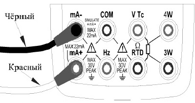
- Подключите чёрный измерительный кабель к выводу mA-, а красный – к mA+.
- Подключите другие концы измерительных кабелей к тестируемому устройству, соблюдая полярность.
- С помощью кнопки mA выберите режим выдачи тока. В основной области экрана будет отображаться значение по умолчанию и единицы измерения по умолчанию.

- Нажмите кнопку 25%100%, после чего внизу экрана отобразится: 25%SET. Повторное нажатие кнопки приводит к отображению индикатора 100%SET. Одновременно будет показано значение по умолчанию.
- Используя кнопки ▲ / ▼, задайте величину выходного сигнала тока.
— При значении «25%» вы можете задавать сигнал с приращением/уменьшением на 4 мА (4/8/12/16/20 мА).
— При значении «100%» вы можете задать сигнал с приращением/уменьшением 16 мА (4 мА/20 мА).
Нажатие кнопки ZERO сбрасывает величину сигнала на значение по умолчанию 4 мА (4,000 mA). - Нажатие кнопки ON приводит к изменению индикатора SOURCE на экране от OFF к ON. Калибратор на-чинает выдавать заданный ток в подключенную цепь.
- Для отключения выдачи сигнала тока снова нажмите кнопку ON. На экране появится индикатор OFF, а сигнал на выходных разъёмах пропадёт.
Воспроизведение силы постоянного тока при работе с калибратором АМ-7111
- Подключите чёрный измерительный кабель к выводу mA-, а красный – к mA+.
- Подключите другие концы измерительных кабелей к тестируемому устройству, соблюдая полярность.
- С помощью кнопки mA выберите режим выдачи тока. В основной области экрана будет отображаться значение по умолчанию и единицы измерения по умолчанию.
- Задайте значение каждого разряда величины на выходе (0…20,000 мА), используя кнопки (▲ / ▼).
- Нажатие кнопки ON приводит к изменению индикатора SOURCE на экране от OFF к ON. Калибратор начинает выдавать заданный постоянный ток между выводными разъёмами.
- Для выключения вывода снова нажмите кнопку ON. На экране появится индикатор OFF, а сигнал между выходными разъёмами пропадёт.
Функция автоматического изменения тока с заданным шагом калибратора АМ-7111
Вы можете задать диапазон (в пределах 4…20 мA), в котором ток будет изменяться с заданным шагом, или выбрать режим свипирования (качание). Для прохождения полного цикла в диапазоне 4…20 мA в режиме свипирования необходимо 80 секунд, а в режиме перебора с заданным шагом – 20 с.
- Подключите чёрный измерительный кабель к выводу mA-, а красный – к mA+.
- Подключите другие концы измерительных кабелей к тестируемому устройству, соблюдая полярность.
- С помощью кнопки mA выберите режим выдачи тока. В основной области экрана будет отображаться значение по умолчанию и единицы измерения по умолчанию.
- Нажмите кнопку

 (в нижней части экрана появится индикатор изменения с заданным шагом – ). Повторное нажатие этой кнопки вызовет индикатор качания значения . Одновременно будет показана величина сигнала по умолчанию (4,000 mA).
 - Нажатие кнопки ON приводит к изменению индикатора SOURCE на экране: от OFF к ON. Калибратор начинает выдавать сигнал тока (по умолчанию 4 мА).
- Нажатие кнопки START запускает режим свипирования значения или изменения с заданным шагом. В нижней части экрана будет показываться индикатор RUN.
- Повторное нажатие кнопки START останавливает свипирование значения или изменения с заданным шагом (символ RUN пропадёт). Текущее значение выдаваемой на терминалах величины сигнала зафиксируется на экране. Для возобновления автоматического изменения параметра после остановки процесса нажмите кнопку START снова. В нижней части экрана снова будет показан индикатор RUN.
- Для выключения вывода снова нажмите кнопку ON. На экране появится индикатор OFF, а сигнал на выходных терминалах пропадёт.
Примечание: Кнопка START позволяет запустить автоматическое изменение значений тока, только когда режим выдачи сигнала находится в состоянии «SOURCE ON».
Воспроизведение напряжения постоянного тока при работе с калибратором процессов АМ-7111
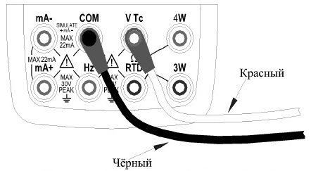
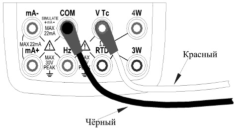
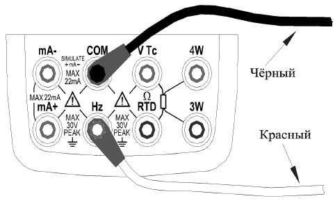
- Подключите чёрный измерительный кабель к выводу COM, а красный – к VTc.
- Подключите другие концы измерительных кабелей к тестируемому устройству, соблюдая полярность.
- С помощью кнопки V выберите функцию выдачи постоянного напряжения (выбрана по умолчанию при включении при-бора), выберите диапазон 100 мВ, 1000 мВ или 10 В с помощью кнопки RANGE. В основной области экрана будет отображаться значение и единицы измерения по умолчанию.
- Задайте значение каждого разряда величины на выходе, используя кнопки ▲ / ▼.
- Нажатие кнопки ON приводит к изменению индикатора SOURCE на экране от OFF к ON. Калибратор начинает выдавать заданное постоянное напряжение между выводными разъёмами.
- Для выключения выдачи сигнала снова нажмите кнопку ON. На экране появится индикатор OFF, а сигнал между выходными разъёмами пропадёт.
Отображение тока в процентах (mA%)
В любом режиме выдачи тока заданное значение отображается в главной области экрана, а значение в процентах (mA%) – в области вторичного параметра. Данное значение рассчитывается по формуле:
мA % = 100% *(текущее выходное значение в мA – 4 мA) / 16 мA
Примечание: Нажатие кнопки T.DISP выводит в области вторичного параметра значение комнатной температуры.
Имитация трансмиттера в диапазоне 4…20 мA
![]()
Подключите калибратор и источник питания токовой петли к тестируемому датчику или контроллеру и действуйте аналогично пункту «Воспроизведение силы постоянного тока».
Воспроизведение электрического сопротивления постоянному току
Калибратор имитирует сопротивление резистора, измеряя тестовый ток от калибруемого устройства (например, от омметра), а затем создавая между выводами напряжение U, пропорциональное заданному сопротивлению R. Таким образом, эквивалентное сопротивление R = U / I. Калибратор выдаёт корректное сопротивление только для устройств, которые поддерживают такой метод.
Допустимый диапазон тестового тока от тестируемого устройства составляет 0,1…3 мА. Для обеспечения хорошей точности, ток должен находиться строго внутри этого диапазона.
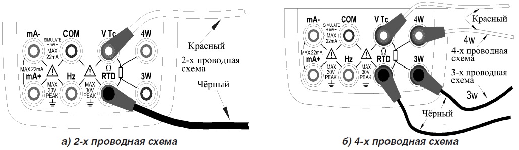
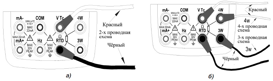
Любое эмулируемое сопротивление не учитывает сопротивления измерительных кабелей. Общее сопротивление, измеряемое на концах кабелей, вычисляется добавлением сопротивления измерительных кабелей (примерно 0,1 Ом на каждый кабель) к эмулируемому значению. Для выдачи точных сопротивлений используйте 3-х или 4-х проводную схемы подключения (см. Рис. Б).
Если ёмкость между вводами калибруемого устройства превышает 0,1 мкФ, калибратор может эмулировать сопротивление некорректно.
- Подключите чёрный измерительный кабель к выводу ΩRTD, а красный – к выводу VTc.
- Подключите другие концы измерительных кабелей к тестируемому устройству, соблюдая полярность.
- С помощью кнопки OHM выберите функцию имитации сопротивления. Кнопкой RANGE выберите нужный диапазон (выбранная функция, значение по умолчанию и единицы измерения отобразятся на экране).
- Установите желаемое значение сопротивления разряд за разрядом, используя кнопки ▲ / ▼.
- Нажатие кнопки ON приводит к изменению экранного индикатора SOURCE из положения OFF в положение ON. Калибратор начинает эмулировать заданное значение сопротивления между выводами.
- Для выключения выдачи сигнала нажмите кнопку ON снова (на экране появится индикатор OFF).
Воспроизведение статических характеристик термопар (Tc) при работе с АМ-7111
Калибратор АМ-7111 оснащён встроенным температурным датчиком. Для калибровки какого-либо прибора со встроенной компенсацией температуры свободного спая (Reference Junction) с помощью выдачи калибратором термо-ЭДС без использования дополнительных средств компенсации свободного спая используйте функцию дат-чика RJ.
- С помощью кнопки Tc выберите функцию имитации термопар (Tс), при этом датчик RJ включается автоматически (на экране появится индикатор RJ-ON). C помощью кнопки RANGE выберите необходимый тип термопары: K, E, J, T, B, N, R, S, L, U. Выбранная функция, тип термопары и единицы измерения будут отображаться в основной ча-сти экрана. Температура измеряется по умолчанию в °C, при необходимости можно выбрать °F.
- Установите выдаваемое значение разряд за разрядом, используя кнопки ▲ / ▼.
- Нажатие кнопки ON приводит к изменению экранного индикатора SOURCE из OFF в ON. Между выходными разъёмами появится термо-ЭДС, рассчитанная с учётом температуры, полученной датчиком RJ.
- Для выключения имитации сигнала снова нажмите кнопку ON (на экране появится индикатор OFF).
Примечание: Если необходимости в функции компенсации свободного спая (RJ) больше нет, для её отключения нажмите кнопку RJ-ON. Калибратор станет использовать внешнюю компенсацию свободного спая, а символ «RJ-ON» исчезнет. Для повторного запуска этой функции нажмите кнопку RJ-ON снова.
Функция мониторинга температуры калибратора процессов АМ-7111
В режиме имитации термопар калибратор АМ-7111 по умолчанию показывает в области дополнительного параметра величину напряжения на выходах прибора (изменяется в зависимости от изменения компенсации свободного спая). Калибратор имеет функцию мониторинга температуры окружающей среды (кнопка T.DISP). При повторном нажатии T.DISP на экране снова отобразится текущее напряжение на выходах прибора.
Воспроизведение статических характеристик термопреобразователей сопротивления (RTD)
Калибратор АМ-7111 эмулирует сопротивление термопреобразователей сопротивления, измеряя тестовый ток от калибруемого устройства (например, от омметра), а затем создавая между выводами напряжение V, пропорциональное заданному сопротивлению R. Таким образом, эквивалентное сопротивление R = V/I. Калибратор выдаёт правильное сопротивление только для устройств, которые поддерживают такой метод.
Допустимый диапазон измерения тестового тока I, получаемого от тестируемого устройства, номинально составляет от 0,1 до 3 мА для термопреобразователей сопротивления типа PT100, Cu10, Cu50; и от 0,05 до 0,3 мА для типа PT200, PT500, PT1000. Для обеспечения хорошей точности, ток должен находиться строго внутри этого диапазона.
Любое эмулируемое сопротивление не учитывает сопротивления измерительных кабелей. Общее сопротивление, измеряемое на концах кабелей, вычисляется добавлением сопротивления измерительных кабелей (примерно 0,1 Ом на каждый кабель) к эмулируемому значению. Для выдачи точных сопротивлений используйте трёхпроводную или четырёхпроводную схемы подключения (см. Рис. Б).
- С помощью кнопки RTD выберите функцию имитации термопреобразователей сопротивления (RTD). С помощью кнопки RANGE выберите нужный тип RTD: PT100, PT200, PT500, PT1000, Cu10, Cu50 (выбранная функция, тип RTD и его сопротивление, соответствующее заданной температуре, а так же диапазон имитации по умолчанию и единицы измерения температуры отобразятся на экране).
- Установите требуемое значение разряд за разрядом, используя кнопки ▲ / ▼.
- Нажатие кнопки ON приводит к изменению экранного индикатора SOURCE из OFF в ON. Калибратор начинает эмулировать заданную величину сопротивления на выходных разъёмах.
- Для выключения вывода снова нажмите кнопку ON (на экране появится индикатор OFF).
Воспроизведение частоты следования и амплитуды прямоугольных импульсов
Калибратор АМ-7111 может выдавать постоянный импульсный сигнал с заданными частотой и амплитудой.
- Подключите чёрный измерительный кабель к выводу COM, а красный – к выводу Hz.
- Подключите другие концы измерительных кабелей к тестируемому устройству, соблюдая полярность.

- С помощью кнопки

 выберите функцию имитации частоты (на экране отобразится индикатор FREQ и частота по умолчанию 10 Гц (10 Hz).
 - С помощью кнопки RANGE выберите нужный частотный диапазон: 100 Гц, 1кГц, 10 кГц, 100 кГц (выбранная функция, диапазон выдачи по умолчанию и единицы измерения будут отображаться в основной части экрана). Диапазон частоты можно изменить нажатием кнопки RANGE только в режиме задания частоты.
- Установите требуемое значение разряд за разрядом, используя кнопки ▲ / ▼.
- Нажатие кнопки Vpeak включает режим задания амплитуды (на экране отображается значение 1V).
- Установите требуемое значение разряд за разрядом, используя кнопки ▲ / ▼.
- Для повторного входа в режим задания частоты нажмите кнопку FREQ.
- Нажатие кнопки ON приводит к изменению экранного индикатора SOURCE из OFF в ON. Калибратор создаёт на выходных разъёмах постоянный импульсный сигнал с заданной частотой и амплитудой.
- Для выключения вывода снова нажмите кнопку ON (на экране появится индикатор OFF).
Примечание: Величина частоты может меняться в любом из положений функции выдачи частоты: ON или OFF. Нажатие кнопки RANGE отключает выходной сигнал.
Воспроизведение числа прямоугольных импульсов при работе с калибратором АМ-7111
Калибратор процессов АМ-7111 может выдавать набор импульсов заданной частоты и амплитуды.
- Подключите чёрный измерительный кабель к выводу COM, а красный – к выводу Hz.
- Подключите другие концы измерительных кабелей к тестируемому устройству, соблюдая полярность.
- С помощью кнопки выберите функцию выдачи импульсов (на экране отобразится частота по умолчанию 10 Hz и индикатор PULSE).
- С помощью кнопки RANGE выберите нужный частотный диапазон: 100 Гц, 1кГц, 10 кГц, 100 кГц (выбранная функция, диапазон выдачи по умолчанию и единицы измерения будут отображаться в основной части экрана). Диапазон частоты можно изменить нажатием кнопки RANGE только в режиме задания частоты.
- Установите требуемое значение разряд за разрядом, используя кнопки ▲ / ▼.
- Нажатие кнопки Vpeak включает режим задания амплитуды (на экране отображается значение 1V).
- Установите требуемое значение разряд за разрядом, используя кнопки ▲ / ▼.
- Нажатие кнопки CYC включает режим задания количества импульсов (по умолчанию: 1 CYC).
- Установите требуемое значение разряд за разрядом, используя кнопки ▲ / ▼.
- Для повторного входа в режим задания частоты нажмите кнопку FREQ.
- Нажатие кнопки Vpeak включает режим задания амплитуды (на экране отображается значение 1V).
- Установите требуемое значение разряд за разрядом, используя кнопки ▲ / ▼.
- Нажатие кнопки ON приводит к изменению экранного индикатора SOURCE из OFF в ON. Калибратор создаёт на выходных разъёмах низкоуровневый сигнал.
- Нажатие кнопки START запускает выдачу калибратором заданного количества импульсов с заданными частотой и амплитудой (на экране отображается индикатор RUN).
- После выдачи набора импульсов вывод автоматически отключается (индикатор RUN исчезает).
- Для выключения вывода снова нажмите кнопку ON (на экране появится индикатор OFF).
Примечание: Когда символ RUN не отображается на экране, вы можете изменить частоту, амплитуду и количество импульсов в любом из положений функции выдачи: ON или OFF. Во время выдачи импульсов нажатие кнопки START останавливает вывод и убирает символ RUN с экрана. Повторное нажатие кнопки START запускает функцию выдачи заново.
Имитация коммутаций при работе с АМ-7111
Вы можете включать или выключать выходные разъёмы, используя функцию имитации коммутаций (в качестве контактного выключателя используется полевой транзистор).
- Подключите чёрный измерительный кабель к выводу COM, а красный – к выводу Hz.
- Подключите другие концы измерительных кабелей к тестируемому устройству, соблюдая полярность.
- С помощью кнопки выберите функцию имитации коммутаций (экран покажет значение по умолчанию 10Hz и символ ).
- С помощью кнопки RANGE выберите нужный частотный диапазон: 100 Гц, 1кГц, 10 кГц, 100 кГц (выбранное значение по умолчанию и единицы измерения будут отображаться на экране).
- Установите требуемое значение разряд за разрядом, используя кнопки ▲ / ▼.
- Нажатие кнопки ON приводит к изменению экранного индикатора SOURCE из положения OFF в положение ON, калибратор начинает выдавать эмулированные коммутации в соответствии с заданной частотой.
- Для выключения вывода нажмите кнопку ON снова (появится индикатор OFF).
Примечание:
- Вы не можете задавать амплитуду и число импульсов в режиме выдачи контакта.
- Контактный сигнал имеет полярность. Обычно подключают положительный полюс к разъёму Hz калибра-тора, а отрицательный полюс – к разъёму COM калибратора.
- Максимально допустимый ток при выдаче контакта составляет 50 мA.
Функция обнуления (ZERO) у калибратора АМ-7111
В любом диапазоне генерации постоянного напряжения, постоянного тока, сопротивления, термопар и термопреобразователей сопротивления, нажатие кнопки ZERO инициирует функцию сброса, которая возвращает заданное выходное значение к настройкам по умолчанию.
Примечание: Для функций выдачи частоты, импульсов и коммутаций функция ZERO недоступна.
Портативный прибор используется для генерации сигналов высокой точности при проверке и калибровке различной аппаратуры (датчики, измерительное оборудование, преобразователи, контроллеры и т.п.) во время проведения работ по ремонту и пуско-наладке.
Применяется инженерами, наладчиками и специалистами ремонтных служб с целью решения обширного диапазона рабочих задач.
Устройство характеризуется высокими показателями точности и быстродействия. Предусмотрена вибрационная защита. Доступны функции обнуления результатов и ручного выбора измерительных пределов.
Питание модели осуществляется от четырёх батареек типоразмера ААА. В целях экономии электроэнергии изделие автоматически отключается через некоторое время бездействия пользователя.
[code1]
Особенности АКТАКОМ АМ-7111:

Защитный прорезиненный хольстер для дополнительной безопасности корпуса.

Удобная панель управления расположена на лицевой стороне.

Информативный жидкокристаллический дисплей с отключаемой подсветкой.
Преимущества АКТАКОМ АМ-7111:
- два комплектных предохранителя;
- скромные габаритные размеры и малый вес;
- зарядка по USB в случае использования аккумуляторов;
- простота и надёжность эксплуатации.
AKTAKOM AM-7111 multifunctional process calibrators are designed to generate high-precision signals when testing and calibrating different types of equipment (probes, measurers, converters, controllers etc.) during repair or adjustment work. These compact handheld devices are necessary for service engineers, they save time and solve a wide range of tasks in field conditions.
Specifications
| Function | Range | Resolution | Accuracy | |
|---|---|---|---|---|
| DC Voltage | 100mV 1000mV 10V |
-10.000…110.000mV -100.00…1100.00mV -1.0000…11.0000V |
1μV 10μV 0.1mV |
±(0.02%+11) |
| DC Current | 20mA | 0.000mA…22.000mA | 1μA | ±(0.02%+0.02) |
| Resistance | 400Ω 4kΩ 40kΩ |
0.00Ω…400.00Ω 0.0000kΩ…4.0000kΩ 0.000kΩ…40.000kΩ |
0.01Ω 0.1Ω 1Ω |
±(0.02%+8) ±(0.02%+10) ±(0.02%+40) |
| Frequency | 100Hz / 1kHz 10kHz / 100kHz |
1.00…110.0 Hz 0.100…1.100 kHz 1.0…11.0 kHz 10…110 kHz |
0.01Hz/ 1Hz 0.1kHz/ 2kHz |
±2 |
| Pulse | 100Hz/ 1kHz 10kHz |
1…100000 | 1 | ±2 |
| Switch | 100Hz / 1kHz 10kHz / 100kHz |
1.00…110.0 Hz 0.100…1.100 kHz 1.0…11.0 kHz 10…110 kHz |
0.01Hz / 1Hz 0.1kHz / 2kHz |
±2 / ±2 ±2 / ±5 |
| Thermocouple | R, S | 0…100…1767°C | 1 °C | 1.5°C / 1.2°C |
| B | 600…800…1820°C | 1.5°C / 1.1°C | ||
| E | -200.0…-100.0…600.0…1000.0°C | 0.1 °C | 0.6°C / 0.5°C / 0.4°C | |
| K | -200.0…-100.0…400.0…1200.0…1372.0°C | 0.6°C / 0.5°C / 0.7°C / 0.9°C | ||
| J | -200.0…-100.0…800.0…1200.0°C | 0.6°C / 0.5°C / 0.7°C | ||
| T | -250.0 °C…400.0°C | 0.6°C | ||
| N | -200.0…-100.0…900.0…1300.0°C | 1.0°C / 0.7°C / 0.8°C | ||
| L | -200.0…0.0…900.0°C | 0.7°C / 0.5°C | ||
| U | -200.0…0.0…600.0°C | 0.7°C / 0.5°C | ||
| Thermistor | Pt100 | -200.0…0.0…400.0°C | 0.1 °C | 0.3°C / 0.5°C |
| Pt200 | -200.0…100.0…300.0…630.0°C | 0.8°C / 0.9°C / 1.0°C | ||
| Pt500 | -200.0…100.0…300.0…630.0°C | 0.4°C / 0.5°C / 0.7°C | ||
| Pt1000 | -200.0…100.0…300.0…630.0°C | 0.2°C / 0.5°C / 0.7°C | ||
| Cu10 | -100.0…260.0°C | 1.8°C | ||
| Cu50 | -50.0…150.0°C | 0.6°C |
- Double 5 digit LCD (50000 counts)
- The basic error: 0.02%
- Power: 4 x 1.5V (AAA)
- Auto power off function which can be disabled
- Dimensions: 205x95x42mm / 8.07×3.7×1.7in
- Weight: 500g / 17.6oz
Standard accessories:
- AM-7111 process calibrator
- Test leads (red and black) — 2 pcs
- Test probes (red and black) — 2 pcs
- Alligator clips (red and black) — 2 pcs
- Fuse: 50 mA/250 V
- Fuse: 63 mA/250 V
- Triple-A batteries: 1.5 V — 2 pcs
Sourcing DC Voltage
Step 1: Using V key to select DC voltage source function, select the desired range from 100mV, 1000mV, and 10V by pressing the RANG key. The default value and unit of the selected source function and range shall be displayed in the main districts part of the LCD.
Step 2: Set the output value digit by digit using ▲ / ▼ keys. Each pair of ▲ / ▼ keys corresponds to each digit of the LCD reading. Each press of ▲ / ▼ key increases or decreases the digit. Increasing the digit from 9 or decreasing it from 0 causes the digit to overflow or underflow, allowing you to set the output value without interruption. Holding down the ▲ / ▼ keys continuously changes the digit in question. And the value won’t change if it is increased or decreased to the Maxim or Minimum value. Pressing ZERO key initializes the output set point to the default value (0).
Step 4: To turn off the output, press the ON key once again. OFF appears on the LCD and no signals sourced between the terminals.
Sourcing DC Current
Step 1: Using mA key to select the desired source function 0-22mA .The default value and unit of the selected source function shall be displayed in the main districts part of the LCD.
Step 2: Set the output value digit by digit using ▲ / ▼ keys.
Each pair of ▲ / ▼ keys corresponds to each digit of the LCD reading. Each press of the ▲ / ▼ key increases or decreases the digit. Increasing the digit from 9 or decreasing it from 0 causes the digit to overflow or underflow, allowing you to set the output value without interruption. Holding down ▲ / ▼ key continuously changes the digit in question. And the value won’t change if it is increased or decreased to the Maxim or Minimum value. Pressing the ZERO key initializes the output set point to the default value (0).
Step 3: Pressing ON key causes the indicator on the LCD to change from OFF to ON. The calibrator sources the preset DC current between the output terminals.
Step 4: To turn off the output, press ON key once again. OFF appears on the LCD and no signals sourced between the terminals.
Sourcing Resistance
- Firstly, the calibrator sources a resistance signal by receiving the resistance-measuring current I supplied from the device being calibrated (such as a resistance meter) and then delivering the voltage V proportional to the preset resistance R between the output terminals, and thus producing the equivalent resistance R =V/I. Consequently, the calibrator sources the signal correctly only for such devices that employ this method of measurement.
- The allowable range of the resistance measuring current I that the calibrator receives from a resistance measuring device under calibration is rated as 0.1 mA to 3 mA. To ensure accuracy, the resistance measuring current I from the device under calibration shall be strictly confined within the range. For further details, see Chapter 14, “Specification”.
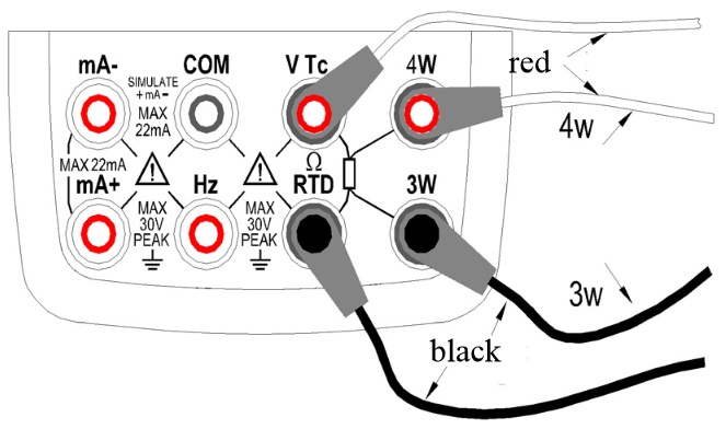
- Any resistance signal being sourced does not include the resistance component of the lead cables for source. The whole resistance, when measured at the ends of the lead cables for source, is given by adding the resistance of the lead cables (approximately 0.1Ω on a round-trip basis) to the sourced resistance signal. For source of precise resistance signals, use three-wire or four-wire connection.(See figure 10)
- If capacitance between the terminals of a device under calibration is greater than 0.1ųF, the calibrator may fail to source correct resistance signals.
Step 1: Using the OHM key, select Ohm function. Using the RANGE key, select the desired range. The selected function and the default range source value and unit shall be shown in the main districts part of the LCD.
Step 2: Set the output value digit by digit using each pair of ▲ / ▼ keys.
Each pair of ▲ / ▼ keys corresponds to each digit of the LCD reading. Each press of the ▲ / ▼ key increases or decreases the digit. Increasing the digit from 9 or decreasing it from 0 causes the digit to overflow or underflow, allowing you to set the output value without interruption. Holding down the ▲ / ▼ key continuously changes the digit in question. And the value won’t change if it is increased or decreased to the Maxim or Minimum value. Pressing the ZERO key initializes the output set point to the default value (0).
Step 3: Pressing the ON key causes the SOURCE indicator on the LCD to change from OFF to ON. The calibrator sources the preset resistance value between the output terminals.
Step 4: To turn off the output, press the ON key once again. The OFF appears on the LCD and no signals sourced between the terminals.
The connection method based on three-wire and four-wire is shown in the below picture:
Simulate Sourcing TC
The calibrator is designed with an internal temperature sensor. To calibrate a device with built-in reference junction temperature compensation by sourcing a thermoelectromotive force with the calibrator without using non-external 0C reference junction compensation means, use the RJ sensor function. Select simulate TC source function, in which RJ senor goes on work automatically. The “RJ-ON” mark displays on the middle part of the screen.
Step 1: Using the Tc key, select simulate TC source function. Using the RANGE key, select the desired range from K, E, J, T, B, N, R, S, L, U. The selected function and the default range source value and unit shall be shown in the main districts part of the LCD.
Step 2: Set the output value digit by digit using each pair of ▲ / ▼ keys.
Each press of ▲ / ▼ key increases or decreases the digit. Increasing the digit from 9 or decreasing it from 0 causes the digit to overflow or underflow, allowing you to set the output value without interruption. Holding down ▲ / ▼ key continuously changes the digit in question. And the value won’t change if it is increased or decreased to the Max. or Min. value. Pressing the ZERO key initializes the output set point to the default value (the default value of a typical B type is 600°C).
Step 3: Pressing ON key causes the SOURCE indicator on the LCD to change from OFF to ON. A thermoelectromotive force based on the temperature detected by the RJ sensor develops between the output terminals.
Step 4: To turn off the output press ON key once again. OFF appears on the LCD and no signals sourced between the terminals.
Note: If you don’t need the reference junction compensation, press the RJ-ON key to shut off. The calibrator source a value with using external 0°C reference junction compensation means, and the RJ-ON mark vanishes. Press the RJ-ON key once more to start the reference junction compensation and the RJ-ON mark displays in the middle of the screen.
Simulate Sourcing RTD
- Firstly, the calibrator sources a resistance signal by receiving the resistance-measuring current I supplied from the device being calibrated (such as a resistance meter) and then delivering the voltage V proportional to the preset resistance R between the output terminals, and thus producing the equivalent resistance R =V/I. Consequently, the calibrator sources the signal correctly only for such devices that employ this method of measurement.
- The allowable range of the resistance measuring current I that the calibrator receives from a resistance measuring device under calibration is rated as 0.1 to 3mA at PT100,Cu10,Cu50, 0.05 to 0.3mA at PT200,PT500,PT1000. To ensure accuracy, the resistance measuring current I from the device under calibration shall be strictly confined within the range. For further details, see Chapter 24, “Specification”.
- Any resistance signal being sourced does not include the resistance component of the lead cables for source. The whole resistance, when measured at the ends of the lead cables for source, is given by adding the resistance of the lead cables (approximately 0.1Ω on a round-trip basis) to the sourced resistance signal. For source of precise resistance signals, use three-wire or four-wire connection.
Step 1: Using the RTD key, select RTD function. Using the RANGE key, select a desired RTD range from PT100, PT200, PT500, PT1000, Cu10, Cu50. The selected function and the default range source value and unit shall be shown in the main districts part of the LCD. Types of RTD shall be shown in the middle part of the LCD.
Step 2: Set the output value digit by digit using each pair of ▲ / ▼ keys.
Each press of ▲ / ▼ key increases or decreases the digit. Increasing the digit from 9 or decreasing it from 0 causes the digit to overflow or underflow, allowing you to set the output value without interruption. Holding down the ▲ / ▼ key continuously changes the digit in question. And the value won’t change if it is increased or decreased to the Maxim or Minimum value. Pressing the ZERO key initializes the output set point to the default value (0).
Step 3: Pressing ON key causes SOURCE indicator on the LCD to change from OFF to ON. The calibrator sources the preset resistance value between the output terminals.
Step 4: To turn off the output, press ON key once again. The OFF appears on the LCD and no signals sourced between the terminals.
Sourcing Frequency
The calibrator can source a constant pulse signal responding to the preset frequency and amplitude.
Step 1: Using ![]()
![]() key, select frequency source function. The LCD shows the default frequency value10 Hz.
key, select frequency source function. The LCD shows the default frequency value10 Hz.
Step 2: Using�RANG key, select a desired frequency range from 100Hz, 1KHz,10kHz,100KHz. The selected function and the default range source value and unit shall be shown in the LCD.
Step 3: Set the output value digit by digit using each pair of ▲ / ▼ output setting keys.
Each pair of ▲ / ▼ keys corresponds to each digit of the LCD reading. Each press of ▲ / ▼ key increases or decreases the digit. Increasing the digit from 9 or decreasing it from 0 causes the digit to overflow or underflow, allowing you to set the output value without interruption. Holding down ▲ / ▼ key continuously changes the digit. And the value won’t change if it is increased or decreased to the Maxim or Minimum value.
Step 4: Pressing the Vpeak key once switches to amplitude setting mode. The LCD provides a reading of 1V.
Step 5: Set the output value digit by digit using each pair of ▲ / ▼ output setting keys.
Each pair of ▲ / ▼ keys corresponds to each digit of the LCD reading. Each press of ▲ / ▼ key increases or decreases the digit. Increasing the digit from 9 or decreasing it from 0 causes the digit to overflow or underflow, allowing you to set the output value without interruption. Holding down ▲ / ▼ key continuously changes the digit. And the value won’t change if it is increased or decreased to the Max. or Min. value.
Step 6: To re-enter into the frequency set mode, press the FREQ key to set the frequency.
Step 7: Pressing�ON key causes the SOURCE indicator on the LCD to change from OFF to ON. The calibrator sources constant pulse signals responding to the preset frequency and amplitude between the output terminals.
Step 8: To turn off the output, press ON key once again. The OFF appears on the LCD and no signals sourced between the terminals.
Sourcing Number of Pulses
The calibrator can source a preset number of pulse signal responding to the preset frequency and amplitude.
Step 1: Using ![]()
![]() key, select pulse source function. The LCD shows the default value10 Hz.
key, select pulse source function. The LCD shows the default value10 Hz.
Step 2: Using the RANGE key, select a desired frequency range from 100Hz, 1KHz, 10kHz. The selected function and the default range source value and unit shall be shown in the LCD.
Step 3: Set the output value digit by digit using each pair of ▲ / ▼ output setting keys.
Each pair of ▲ / ▼ keys corresponds to each digit of the LCD reading. Each press of ▲ / ▼ key increases or decreases the digit. Increasing the digit from 9 or decreasing it from 0 causes the digit to overflow or underflow, allowing you to set the output value without interruption. Holding down ▲ / ▼ key continuously changes the digit . And the value won’t change if it is increased or decreased to the Maxim or Minimum value.
Step 4: Pressing the Vpeak key once switches to amplitude setting mode. The LCD provides a reading of 1V.
Step 5: Set the output value digit by digit using each pair of ▲ / ▼ output setting keys.
Each pair of ▲ / ▼ keys corresponds to each digit of the LCD reading. Each press of ▲ / ▼ key increases or decreases the digit. Increasing the digit from 9 or decreasing it from 0 causes the digit to overflow or underflow, allowing you to set the output value without interruption. Holding down ▲ / ▼ key continuously changes the digit. And the value won’t change if it is increased or decreased to the Max. or Min. value.
Step 6: Pressing CYC key ,enter into the pulse number set mode, and the LCD shows the default number of 1 CYC.
Step 7: Set the output value digit by digit using each pair of ▲ / ▼ output setting keys.
Each pair of ▲ / ▼ keys corresponds to each digit of the LCD reading. Each press of ▲ / ▼ key increases or decreases the digit. Increasing the digit from 9 or decreasing it from 0 causes the digit to overflow or underflow, allowing you to set the output value without interruption. Holding down ▲ / ▼ key continuously changes the digit. And the value won’t change if it is increased or decreased to the Max. or Min. value.
Step 8: To re-enter into the frequency set mode, press FREQ key to set the frequency.
Step 9: Pressing ON key causes the SOURCE indicator on the LCD to change from OFF to ON, and the calibrator sources low level between the output terminals.
Step 10: Pressing START key the calibrator sources the set number of pulse responding to the preset frequency and amplitude, LCD shows the symbol RUN.
Step 11: When source is complete, the calibrator automatically turns off the output and ceases operation. RUN symbol disappears from the LCD.
Step 12: To turn off the output, press ON key once again. OFF appears on the LCD and no signals sourced between the terminals.
Sourcing Switch
You can turn on or off the output terminals by using the contact output function. An FET is used as the contact-switching device.
Step 1: Using ![]()
![]() key, select the contact output source function. The LCD shows the default value 10Hz,and
key, select the contact output source function. The LCD shows the default value 10Hz,and ![]() symbol.
symbol.
Step 2: Using RANGE key select the desired frequency from 100Hz, 1KHz, 10 KHz and 100KHz. The LCD shows the default value and unit.
Step 3: Set the output value digit by digit using each pair of ▲ / ▼ output setting keys.
Each pair of ▲ / ▼ keys corresponds to each digit of the LCD reading. Each press of ▲ / ▼ key increases or decreases the digit. Increasing the digit from 9 or decreasing it from 0 causes the digit to overflow or underflow, allowing you to set the output value without interruption. Holding down ▲ / ▼ key continuously changes the digit. And the value won’t change if it is increased or decreased to the Max. or Min. value.
Step 4: Pressing ON key causes the SOURCE indicator on the LCD to change from OFF to ON and the calibrator sources contact signals responding to the present frequency.
Step 5: To turn off the output, press ON key once again. The OFF appears on the LCD and no signals sourced between the terminals.
Zero-off function
In any range of DC voltage, DC current, ohm, TC and RTD functions, pressing ZERO key selects clearing off function which initializes the preset source value for the convenience of user to reset source value.
In frequency, pulse, contact output functions ZERO key is unavailable.
Frequently Asked Questions
| Can I set auto power-off time when operating AM-7111 calibrator? |
|---|
Tips: Zero default value (0) represents no automatic power-off function. Up |
| How can I set the backlight time of AM-7111 calibrator? |
|---|
Tips: When the default value is 0, the backlight won’t be off automatically except that you turn it off manually. Up |
| Can I change the temperature unit when working with AM-7111? |
|---|
Up |
| Does AKTAKOM AM-7111 process calibrator have auto power off function? |
|---|
|
Yes, it does. There is Auto Power Off function in AM-7111 and it�s off on default. Up |
-
Contents
-
Table of Contents
-
Bookmarks
Quick Links
Related Manuals for Aktakom AM-1171
Summary of Contents for Aktakom AM-1171
-
Page 2: Table Of Contents
www.tmatlantic.com Contents Ⅰ. General………………………………. — 1 — Ⅱ. Open-package Inspection…………………………- 1 — Ⅲ. Safety Note…………………………….- 2 — Ⅳ. Description of Safety Symbols……………………….- 3 — Ⅴ. Description of Instrument Panel and Pushbutton Functions ……………….. — 3 — Ⅵ. Other Functions…………………………..- 4 — Ⅶ.
-
Page 3: Ⅲ. Safety Note
www.tmatlantic.com Ⅲ. Safety Note In accordance with IEC1010 clause (the safety standard issued by International Electrotechnical Commission), IT is designed and produced according to the safety requirements of pollution level Ⅱ. Warning: In order to avoid endangering the operator’s safety, prior to the operation of the instrument, please read the instruction manual carefully, and conform to the safety warning information and operation instruction strictly to use the instrument.
-
Page 4: Ⅳ. Description Of Safety Symbols
www.tmatlantic.com Ⅳ. Description of Safety Symbols Warning! Battery Undervoltage High Voltage! Danger! AC/DC In accordance with the instructions of European Ground Trade Union Double Insulation Fuse Ⅴ. Description of Instrument Panel and Pushbutton Functions 1. Instrument model. 2. LCD display area. 3.
-
Page 5: Ⅵ. Other Functions
www.tmatlantic.com Input Port: Measure the positive input terminal of voltage, frequency, resistance, capacitance, diode as well as on-and-off test, and insert red meter pen. 7. 10A current input jack: Measure the positive input terminal of 10A shift AC/DC current, and insert red meter pen. 8.
-
Page 6: Ac Voltage (Acv)
www.tmatlantic.com polarity of the red meter pen wire and the tested voltage value are spontaneously displayed on the display. Caution: a)Voltages over DC1000V or AC750V cannot be tested. b) When measuring high voltages, special precautions must be taken to avoid electrical shock.When measurement is completed, immediately disconnect the meter pen and the measured circuit.
-
Page 7: Dc Current (Dca)
www.tmatlantic.com X. DC Current (DCA) 1. Press the “ “ button or “ “ button. Plug the black meter pen into the terminal of “COM” and the red meter pen nto the terminal of “mA” or “10A”. See the picture below. 2.
-
Page 8: Resistance
www.tmatlantic.com Overload protection: 0.6A/250V fuse; 10A/250V fuse. Frequency response: 40-400Hz. Duty Cycle Display: (0.1%-99.9%). XII. Resistance 1. Press “ “ button, and respectively plug the red and black meter pens into the holes of “ ”and “COM”. switch 2.Circularly press “ “…
-
Page 9: Capacity (C)
www.tmatlantic.com Measurement Range Display value condition Forward DC current Diode forward is about 1.0mA, and voltage drop backward voltage is about 3.0V. diode If Buzzer emits a switch buzzer long sound and the switch Open circuit voltage resistance of the is about 1.2V points measured as 30Ω…
-
Page 10: Xvi.temperature Measurement
www.tmatlantic.com Range Accuracy Resolution 10Hz 0.001Hz 100Hz 0.01Hz 1000Hz ±(0.3%+2d) 10kHz 10Hz 100kHz 100Hz 1MHz 1kHz 20MHz 10kHz Input sensitivity: 1.5V effective value. Overload protection: 250VDC or alternating peak XVI.Temperature Measurement 1. Press » » button over 2 seconds, select temperature mode for celsius measurement. Meanwhile, the temperature symbol will be displayed.
-
Page 11: Xviii.instrument Maintenance
www.tmatlantic.com 2. Connect the instrument to computer by USB cable. See the picture on the right: 3. Press “RS232/REL” over 2 seconds and the “RS232/REL” symbol will be displayed on screen. 4. Once the testing data is transmitted to computer,you could start recording, analyzing, processing and printing the data. For more details, please kindly refer to instructions in the software.