Ультразвуковой аппарат ALOKA ProSound 6 и ALPHA 6 (Premier)
Не производится
Цена по запросу
- Дисплей: Цветной
- Расположение: Стационарный
- Класс: Высокий
- Монитор: 12”/17″ ЖК LCD
- Режимы: В, В/В, В/М, М
- Есть аналоги
- Динамический контроль апертуры
- Режим брахитерапии
- Кинопетля на 1300 кадра
По вопросу приобретения запчастей и датчиков к данному УЗИ-аппарату свяжитесь с нами по телефону +7 (495) 215-28-56 или электронной почте info@aloka.su
➠ Аналог — PROSOUND F37
➠ Аналог — ARIETTA 50
ALOKA ProSound 6 и ALPHA 6 (Premier) – ультразвуковые сканеры с жидкокристаллическим LCD-дисплеем, широким ассортиментом датчиков, с тканевой гармоникой и поддержкой работы в сетях по протоколу DICOM 3.0 (опционально). Несмотря на компактность и малогабаритность конструкции, даные аппараты отвечают всем стандартам качества.
- Монитор ЖК LCD 12” (LCD 17″)
- Компактная настроенная флеш-память
- Датчики, созданные по широкополосной технологии с высокой плотностью элементов Wideband Super High Density (W-SHD) – такие же, как в моделях более высоких классов.
- Динамическая фокусировка изображения
- Динамический контроль апертуры
- Динамический контроль частоты датчика в зависимости от глубины исследования
- Режим брахитерапии.
Отличие моделей. Технические характеристики у данных УЗИ-аппаратов во многом совпадают. Однако имеются некоторые отличия: увеличенная кинопамять, встроенная алфавитно-цифровая клавиатура, шумоподавление AIP, компаундинг SCI, встроенный блок ускорения для дополнительных функций.
|
Дисплей УЗИ-сканера |
Диагональ 12” (или 17 на выбор): ЖК безбликовый, подвижный, с фильтром, 256 градаций серого цвета. |
|
Режимы визуализации |
В-режим, В/В, В/М, М-режим, с максимальной частотой кадров 238. |
|
Кинопетля |
на 1300 кадра |
|
Возможность дополнительного соединения с СD ROM, видеопринтером, дисплеем физиосигналов (ЭКГ синхронизированных с В режимом) |
есть |
|
Поддержка работы более 24 разнообразных датчиков |
|
|
17 встроенных изменяемых программ настроек визуализации |
для разных видов исследований |
|
Видео входы/выходы |
есть |
|
Тканевая гармоника |
Позволяет значительно снизить помехи, которые обычно связаны с переотражением и боковыми лепестками. |
|
Количество коннекторов для датчиков |
2 шт. |
|
Управление данными изображений в цифровом формате |
|
|
Память |
999 изображений на встроенной флеш карте |
Комплектация ультразвуковых аппаратов
- УЗИ-аппарат
- Пакет урологических вычислений, пакет акушерских и гинекологических вычислений, кардиовычисления. Имеет режим брахитерапии.
- Датчики многочастотные (до 4 несущих частот), поддержкой второй тканевой гармоники (до 4 частот).
- Поддержка работы в сетях по протоколу DICOM 3.0 (опция)
- 2 коннектора для датчиков.
- С акушерско-гинекологическими, урологическими и кардиологическими отчетами.
- Видео входы/выходы.
- Инструкция на русском языке.
- UST-9123 Конвексный датчик с частотой 2,5/3,8/5,0/6,0 МГц, радиусом 60 мм, углом обзора 60 град. для абдоминальных исследований, акушерства/гинекологии, урологии с поддержкой функции тканевой гармоники (2,1P/2,1S/2,1R/2,1H)
Датчики УЗИ-сканера ALOKA ProSound 6
Конвексные датчики:
- UST-9123 Датчик конвексный абдоминальный супервысокой проницаемости для брюшной полости, акушерства/гинекологии, В:2.8/3.8/5.0/6.0, 60гр., 60mmR, поддержкой гармонического эхо,возможностью пункционного адаптера MP-2473
- UST-9127 Датчик конвексный абдоминальный супервысокой проницаемости для брюшной полости, акушерства/гинекологии, В:2.5/3,8/5.0/6.0, 60гр., 60mmR поддержкой гармонического эхо1,9/2,1/2,5/2,5 Мгц
- UST-9102-3.5-U Датчик конвексный абдоминальный супервысокой проницаемости (интеркостальный доступ), В:3.0/3.75/5.0/6.0, 90гр., 20mmR, возможностью пункционного адаптера MP-2414C
- UST-9124 Датчик конвексный эндополостной, трансвагинальный супервысокой проницаемости, В:3.8/5.0/6.0/7.5, 180гр., 9mmR,возможностью пункционного адаптера
- UST-995-7.5 Датчик конвексный интраоперационный супервысокой проницаемости, В:5.0/6.0/7.5/10.0, 65гр., 20mmR
- UST- MC11-8731 Датчик интраоперационный пальчиковый 5,0/6,0/7,5/10,0 Мгц, углом обзора 65градусов радиусом 20мм.
- UST-987-7.5 Датчик конвексный для исследования малых органов, нейросонографии у детей супервысокой проницаемости, В:5.0/6.0/7.5/10.0, 65гр., 20mmR
- UST-676P Датчик конвексный трансректальный (end fire), В:3.8/5.0/6.0/7.5,180гр., 9mmR, пункционный с стандартной насадкой в комплекте
- UST-9133 Датчик микроконвексный секторный интеркостальный с возможностью биопсии, диаметром 20 мм,поддержкой второй гармоники,В:3,0/3,8/5,0/6,0 THE 2,1 CF 2,!/2,5/3,0/3,8, шириной 13мм , биопсийная насадка MP-2781-опция.
Линейные датчики:
- UST-5045Р-3.5 Датчик линейный пункционный/биопсийный с центральным расположением пункционного канала, супервысокой проницаемости, В:3.0/3.75/5.0/6.0, 80mm
- UST-5710-7.5 Датчик линейный для исследования малых органов супервысокой проницаемости, В:5.0/6.0/7.5/10.0, 60mm, возможностью биопсийной насадки MP-2456
- UST- 5413 Датчик линейный для исследования малых органов и сосудов поверхностно расположенных с управляемым УЗ лучем супервысокой проницаемости,поддержкой тканевой гармоники. В:5.0/6.0/7.5/10.0, 38mm
- UST-5542 Датчик электронный линейный для поверхностных тканей (мускулы, сухожилия),сосудов с управляемым УЗ лучом В/М:7.5/10.0/13.0, 29mm
Биплановый секторно/линейный датчик
- UST-672-5.0/7.5 Датчик конвексный/линейный трансректальный супервысокой проницаемости, Конвексный:120deg./9mmR, В:3.75/5.0/6.0/7.5, Линейный:60mm, В:5.0/6.0/7.5/10.0
В наличии документация на медицинское оборудование фирмы Aloka (в т.ч. на русском языке):
Сервисная инструкция (Service manual) на ProSound 2 [Aloka] Диагностика-УЗИ
![Сервисная инструкция Service manual на ProSound 2 [Aloka]](https://medtechnic.net.ua/img_d/6587.jpg "Сервисная инструкция Service manual на ProSound 2 [Aloka]")
Сервисная инструкция (Service manual) на ProSound 6 [Aloka] Диагностика-УЗИ
![Сервисная инструкция Service manual на ProSound 6 [Aloka]](https://medtechnic.net.ua/img_d/6585.jpg "Сервисная инструкция Service manual на ProSound 6 [Aloka]")
Инструкция по эксплуатации (Operation (Instruction) manual) на Prosound Alpha-10 [Aloka] Диагностика-УЗИ
![Инструкция по эксплуатации Operation (Instruction) manual на Prosound Alpha-10 [Aloka]](https://medtechnic.net.ua/img_d/6618.jpg "Инструкция по эксплуатации Operation (Instruction) manual на Prosound Alpha-10 [Aloka]")
Руководство пользователя (Users guide) на Prosound Alpha-6 [Aloka] Диагностика-УЗИ
![Руководство пользователя Users guide на Prosound Alpha-6 [Aloka]](https://medtechnic.net.ua/img_d/8555.jpg "Руководство пользователя Users guide на Prosound Alpha-6 [Aloka]")
Инструкция по эксплуатации (Operation (Instruction) manual) на Prosound Alpha-7 [Aloka] Диагностика-УЗИ
![Инструкция по эксплуатации Operation (Instruction) manual на Prosound Alpha-7 [Aloka]](https://medtechnic.net.ua/img_d/8556.jpg "Инструкция по эксплуатации Operation (Instruction) manual на Prosound Alpha-7 [Aloka]")
Сервисная инструкция (Service manual) на Prosound Alpha-7 [Aloka] Диагностика-УЗИ
![Сервисная инструкция Service manual на Prosound Alpha-7 [Aloka]](https://medtechnic.net.ua/img_d/5686.jpg "Сервисная инструкция Service manual на Prosound Alpha-7 [Aloka]")
Сервисная инструкция (Service manual) на SSD-1000 (Rev. 0) [Aloka] Диагностика-УЗИ
![Сервисная инструкция Service manual на SSD-1000 (Rev. 0) [Aloka]](https://medtechnic.net.ua/img_d/5903.jpg "Сервисная инструкция Service manual на SSD-1000 (Rev. 0) [Aloka]")
Сервисная инструкция (Service manual) на SSD-1000 (Rev. 2) [Aloka] Диагностика-УЗИ
![Сервисная инструкция Service manual на SSD-1000 (Rev. 2) [Aloka]](https://medtechnic.net.ua/img_d/5711.jpg "Сервисная инструкция Service manual на SSD-1000 (Rev. 2) [Aloka]")
Сервисная инструкция (Service manual) на SSD-1100 [Aloka] Диагностика-УЗИ
![Сервисная инструкция Service manual на SSD-1100 [Aloka]](https://medtechnic.net.ua/img_d/4083.jpg "Сервисная инструкция Service manual на SSD-1100 [Aloka]")
Сервисная инструкция (Service manual) на SSD-1400 [Aloka] Диагностика-УЗИ
![Сервисная инструкция Service manual на SSD-1400 [Aloka]](https://medtechnic.net.ua/img_d/5688.jpg "Сервисная инструкция Service manual на SSD-1400 [Aloka]")
Сервисная инструкция (Service manual) на SSD-1700 [Aloka] Диагностика-УЗИ
![Сервисная инструкция Service manual на SSD-1700 [Aloka]](https://medtechnic.net.ua/img_d/5685.jpg "Сервисная инструкция Service manual на SSD-1700 [Aloka]")
Сервисная инструкция (Service manual) на SSD-210DX II [Aloka] Диагностика-УЗИ
![Сервисная инструкция Service manual на SSD-210DX II [Aloka]](https://medtechnic.net.ua/img_d/5710.jpg "Сервисная инструкция Service manual на SSD-210DX II [Aloka]")
Сервисная инструкция (Service manual) на SSD-3500 [Aloka] Диагностика-УЗИ
![Сервисная инструкция Service manual на SSD-3500 [Aloka]](https://medtechnic.net.ua/img_d/5722.jpg "Сервисная инструкция Service manual на SSD-3500 [Aloka]")
Инструкция по эксплуатации (Operation (Instruction) manual) на SSD-3500 (MN1-5099 версия 0) [Aloka] Диагностика-УЗИ
![Инструкция по эксплуатации Operation (Instruction) manual на SSD-3500 (MN1-5099 версия 0) [Aloka]](https://medtechnic.net.ua/img_d/3680.jpg "Инструкция по эксплуатации Operation (Instruction) manual на SSD-3500 (MN1-5099 версия 0) [Aloka]")
Инструкция по монтажу (Installation instructions) на SSD-3500/3500V [Aloka] Диагностика-УЗИ
![Инструкция по монтажу Installation instructions на SSD-3500/3500V [Aloka]](https://medtechnic.net.ua/img_d/1684.jpg "Инструкция по монтажу Installation instructions на SSD-3500/3500V [Aloka]")
Сервисная инструкция (Service manual) на SSD-4000 [Aloka] Диагностика-УЗИ
![Сервисная инструкция Service manual на SSD-4000 [Aloka]](https://medtechnic.net.ua/img_d/5487.jpg "Сервисная инструкция Service manual на SSD-4000 [Aloka]")
Руководство оператора (Operators Guide) на SSD-500 [Aloka] Диагностика-УЗИ
![Руководство оператора Operators Guide на SSD-500 [Aloka]](https://medtechnic.net.ua/img_d/3441.jpg "Руководство оператора Operators Guide на SSD-500 [Aloka]")
Сервисная инструкция (Service manual) на SSD-500 (Rev.12) [Aloka] Диагностика-УЗИ
![Сервисная инструкция Service manual на SSD-500 (Rev.12) [Aloka]](https://medtechnic.net.ua/img_d/9144.jpg "Сервисная инструкция Service manual на SSD-500 (Rev.12) [Aloka]")
Сервисная инструкция (Service manual) на SSD-500 (Rev.2) [Aloka] Диагностика-УЗИ
![Сервисная инструкция Service manual на SSD-500 (Rev.2) [Aloka]](https://medtechnic.net.ua/img_d/3440.jpg "Сервисная инструкция Service manual на SSD-500 (Rev.2) [Aloka]")
Сервисная инструкция (Service manual) на SSD-5500 [Aloka] Диагностика-УЗИ
![Сервисная инструкция Service manual на SSD-5500 [Aloka]](https://medtechnic.net.ua/img_d/5692.jpg "Сервисная инструкция Service manual на SSD-5500 [Aloka]")
Инструкция по монтажу и эксплуатации (Installation and operation) на SSD-5500 [Aloka] Диагностика-УЗИ
![Инструкция по монтажу и эксплуатации Installation and operation на SSD-5500 [Aloka]](https://medtechnic.net.ua/img_d/4810.jpg "Инструкция по монтажу и эксплуатации Installation and operation на SSD-5500 [Aloka]")
Сервисная инструкция (Service manual) на SSD-630 Version 6 [Aloka] Диагностика-УЗИ
![Сервисная инструкция Service manual на SSD-630 Version 6 [Aloka]](https://medtechnic.net.ua/img_d/5717.jpg "Сервисная инструкция Service manual на SSD-630 Version 6 [Aloka]")
Сервисная инструкция (Service manual) на SSD-680EX /SSD-680STD [Aloka] Диагностика-УЗИ
![Сервисная инструкция Service manual на SSD-680EX /SSD-680STD [Aloka]](https://medtechnic.net.ua/img_d/5661.jpg "Сервисная инструкция Service manual на SSD-680EX /SSD-680STD [Aloka]")
Сервисная инструкция (Service manual) на SSD-900 [Aloka] Диагностика-УЗИ
![Сервисная инструкция Service manual на SSD-900 [Aloka]](https://medtechnic.net.ua/img_d/4108.jpg "Сервисная инструкция Service manual на SSD-900 [Aloka]")
")

Компания Hitachi Aloka Medical (Япония) известна в медицинском мире как производитель надежного и качественного диагностического медоборудования.
Подробнее о товаре
В стоимость входит:
|
Кат. № |
Наименование |
К-во |
|
Аппарат ультразвуковой диагностический с принадлежностями ALOKA ProSound Alpha 6 Premier. Универсальная, полностью цифровая цветовая ультразвуковая диагностическая система экспертного класса, обеспечивающая непревзойденного качества изображения, расширенные возможности обработки данных и высокий уровень эргономики. Формы представления изображения: В,М,D (PW-импульсно-волновой допплер, HPRF PW, CW-постоянно-волновой допплер); M(Flow), M(Power Flow) Dual B, Quad B; B (Flow) и M(Flow) B и M, B и D; B (Flow) и D B,M и D; B и B (Flow) D(Flow), B(Power); B и B (Power Flow) Dual B(Flow), Quad B(Flow) B (Flow), M(Flow), и D eFlow и направленного eFlow – новая высокочувствительная технология исследования кровотока Dual B(Power Flow),Quad B(Power Flow) TDI –тканевой допплер Режим панорамного сканирования Режим 3D методом свободной руки Анатомический М-режим Режим 4D(3D в режиме реального времени)-опция Режим контрастной гармоники- опция |
1 |
|
|
Интерфейс пользователя: 17 дюймовый высокоразрешающий безбликовый цветной подвижный ЖК монитор Бесчересстрочная развертка изображения Регулируемая по высоте и перемещающаяся в горизонтальной и вертикальной плоскостях консоль управления Управление аппаратом через 10 дюймовую Touch панель Виртуальная клавиатура Отдельная выдвижная клавиатура –в базе Совместимость с форматом DICOM Инструкция к эксплуатации на русском языке. Вес сканера -70 кг. |
||
|
UST-9123 |
Датчик конвексный абдоминальный супервысокой проницаемости для брюшной полости, акушерства/гинекологии, В:3.08/4.0/5.0/5.71 МГц, PW/F2.11/2.5/3.0/3.64 МГц, 60 град., 60mmR, с поддержкой гармонического эхо в частотах 1,82/2,0/2,11/2,5 МГц. Поддерживает функцию панорамного изображения, компаундного эхо, тканевого допплера, объемного изображения методом «свободной руки». |
1 |
|
UST-5413 |
Датчик для исследования периферических сосудов и малых органов с управляемым лучом, с частотами 6,67/8,0/10,0/13,3 МГц, в допплеровском режиме — 5,0/6,0/8,0 МГц, с апертурой 36 мм, с поддержкой гармонического эхо в частотах 5,0/5,7/7,2/8,0 МГц, трапециевидного изображения, панорамного изображения, компаундного эхо, функции eTracking. |
1 |
|
UST-9124 |
Датчик конвексный эндополостной, ректовагинальный супервысокой проницаемости, В:3.64/5.0/6.67/8,0 МГц, PW/F:3.64/4,00/5.0/5,71 МГц, 180 град., 9mmR, возможность пункционного адаптера. |
1 |
|
UST-5299 |
Датчик электронный для исследования сердца взрослого, транскраниального допплера, с фазированной решеткой, В/М: 2.1/2.5/3.0/3.64 МГц, PW/F: 2.0/2.5/3.0/3.64 МГц, СW: 4,0 МГц, поддержкой тканевого допплера 1,82 МГц, углом 90 град. |
1 |
|
UCW-ALPHA6 |
Блок непрерывно-волнового допплера |
1 |
|
SOP-ALPHA6-1 |
Программа панорамного изображения |
|
|
SOP-ALPHA6-3 |
Программа обведения и расчета кривой допплеровского спектра в режиме реального времени |
1 |
|
SOP-ALPHA6-5 |
Анатомический (свободный) М-режим |
1 |
|
SOP-ALPHA6-37 |
Программа создания объемного (3D) изображения методом «свободной руки» (объемная реконструкция) |
1 |
|
UP-X898MD |
Устройство для печати монохромных медицинских изображений |
1 |
|
Ippon Smart Winner 1500 |
Источник бесперебойного питания |
1 |
По данным Всемирной организации здравоохранения смертность от сердечно-сосудистых заболеваний является самой распространённой в мире. Атеросклероз на сегодня является очень распространённым и неприятным заболеванием. Зачастую он развивается параллельно с ишемической болезнью сердца. Последствиями атеросклероза могут быть как инфаркты, так и инсульты, вследствие закупорки сосудов.
В последнее время появился ряд методик, позволяющий предсказать развитие атеросклероза у конкретного человека до появления основных клинических признаков — атеросклеротических бляшек. Для этого рассчитываются специальные параметры-предикторы, которые служат метками при диагностике атеросклероза. Затем по таблицам, полученным в результате статистических исследований, определяется, насколько эти параметры близки к норме. В этой статье мы рассмотрим некоторые из этих параметров и медицинское оборудование, которое позволяет их получать.
1. Толщина комплекса интима-медиа (КИМ)
Сосуд состоит из трёх оболочек и просвета:
— Интима (intima) — внутренняя
— Медиа (media) — средняя
— Адвентициа (adventitia) — наружная.
— Просвет сосуда (lumen)

Основные поражения, возникающие при атеросклерозе сосредоточены в интиме, именно в ней формируются атеросклеротические бляшки. Толщина комплекса интима-медиа (КИМ, или IMT — intima-media thickness) является предиктором (раннем маркером) атеросклероза и ишемической болезни сердца (ИБС). КИМ можно измерить с помощью ультразвукового исследования. Измерение проводится в В-режиме ультразвуковым линейным датчиком с апертурой 30-45 мм на высоких частотах (10-15 МГц). В качестве сосудов исследования выбирают обычно общую сонную (CCA) и общую бедренную (CFA) артерии, т.к. эти сосуды проще всего вывести в нужную проекцию для измерения комплекса интима-медиа.
В большинстве старых ультразвуковых сканерах измерение КИМ проводится вручную. Врач выводит проекцию сосуда на монитор и на глаз устанавливает маркеры — края измерения. Методика предполагает измерение на участке артерии протяжённостью 1 см, поэтому врач проводит измерение в нескольких участках.
 Рис. Измерение комплекса интима-медиа вручную.
В современных ультразвуковых сканерах появилась функция автоматического измерения комплекса интима-медиа. Врачу необходимо только вывести проекцию сосуда и установить рамку на стенку сосуда. Прибор автоматически произведёт оконтуривание интимы, медии и вычислит максимальное, минимальное и среднее значения толщины КИМ.

Рис. Автоматическое измерение комплекса интима-медиа (УЗ-сканер ALOKA Alpha 7)
Как выглядит автоматическое измерение толщины комплекса интима-медиа Вы можете посмотреть на видеоролике ниже (снято на ультразвуковом сканере с функцией AutoIMT):
Технически автоматическое оконтуривание может проводиться разными способами. В большинстве случаев применяется анализ амплитуд в В-режиме разными математическими моделями (градиентный анализ, поиск граней, метод деформируемых моделей, метод Discrete Dynamic Contour). Расчёт идет сразу по сотням точек, что невозможно сделать вручную. В данном случае важен не столько метод, сколько то, что анализ проводится по тому же самому изображению, по которому проводится и ручной анализ.
Насколько точнее автоматическое измерение по сравнению с ручным? Медики провели стастистические исследования и обнаружился интересный факт: вариабильность (разброс) значений измеренных вручную больше, чем при автоматическом измерении, однако расчет среднего значения КИМ (Mean IMT) в обоих случаях даёт практически одинаковый результат.
Поэтому мы не говорим здесь о разрешающей способности и точности измерения, т.к. как мы отметили выше данные в обоих случаях используются из одного и того же изображения. Точность такого исследования не больше 0,01 мм (10 мкм). Исключением являются специальные технологии радиочастотного измерения, когда при автоматическом поиске контуров стенок сосуда используется не данные ультразвука, а данные, полученные на радиочастоте. Такие методики разработаны у компании ALOKA (Япония) и Esaote (Италия). Их точность достигает 1 мкм. Однако для статичного измерения КИМ преимущество данных методик не высокое. Оно оправдано при исследовании эластичности стенок сосуда, речь о котором пойдёт ниже.

Рис. Автоматическое измерение КИМ радиочастотным методом
на УЗ-сканере фирмы Esaote, точность 1 мкм (0,001 мм).
Тут стоит перейти к клиническому значению этих параметров. Среднее значение толщины интима-медиа может быть проанализировано с помощью таблиц, сформированных в ходе Мангеймского соглашения (Mannheim Carotid IMT Consensus 2004-2006). Данное соглашение между врачами показывает, как правильно измерять комплекс интима-медиа и интерпретировать полученные данные. Текст соглашения можно прочитать внизу статьи по ссылкам в списке литературы.
Среди прочего, в соглашении имеется таблица риска развития сердечно-сосудистых заболеваний. Данные получены в ходе массового сбора статистики при обследовании пациентов. Во многие ультразвуковые сканеры эта таблица встроенна в программу исследования сосудов. На изображении ниже приведена эта таблица из УЗ-сканера фирмы MEDISON.
 Рис. Риск развития сердечно-сосудистых заболеваний согласно Мангеймскому консенсусу.
По левой оси расположено среднее значение КИМ, по нижней оси расположены возрастные группы пациентов. Цветными прямоугольниками показан разброс значений средней толщины КИМ при заданном количестве факторов риска (от 0 до 3 и более). Количество факторов риска подсчитывается исходя из осмотра и общения с пациентом — к ним относятся такие факторы, как курение, ожирение, гипертония и т.д. Если КИМ пациента попадает в пределы прямоугольника для заданного количеста факторов риска, то вероятность развития сердечно-сосудистых заболеваний оценивается как средняя, если выше прямоугольника — то высокая.
Максимальное значение КИМ (Max IMT) позволяет говорить о том, есть ли у пациента атеросклеротические бляшки или нет. Согласно тому же Мангеймскому соглашению бляшка есть, если Max IMT = 1.5 мм и более. Наличие атеросклеротических бляшек говорит о переходе атеросклероза на другую стадию.
Итоговая таблица по методам измерения толщины комплекса интима-медиа (IMT) приведена ниже:
| Оборудование | Точность измерения | Точность при расчёте среднего значения Mean IMT и максимального Max IMT | Вариабильность (разброс значений при измерении КИМ) | Скорость измрения | |
| Ручное измерение | Практически любой УЗИ сканер с высокочастотным линейным датчиком | 0,1 мм | статистически допустимая | высокая | низкая |
| Автоматическое измерение (B-режим) |
Современный УЗИ сканер с опцией AutoIMT и высокочастотным линейным датчиком | 0,01 мм | статистически допустимая | низкая | высокая |
| Автоматическое измерение (радиочастотный метод) |
УЗИ сканер Esaote с функцией RF-QIMT и специальным высокочастотным линейным датчиком | 0,001 мм | статистически допустимая | очень низкая | высокая |
Итак, при измерении толщины КИМ мы рекомендуем использовать метод автоматического измерения без использования радиочастоты. Этот метод наиболее доступен, экономит время врача при проведении исследования и автоматически подсчитывает все необходимые параметры для занесения в протокол.
2. Эластичность стенок сосуда и скорость распространения пульсовой волны (PWV)
Ещё одним предиктором атеросклероза является эластичность стенок сосуда и скорость распространения пульсовой волны (Pulse Wave Velocity — PWV). Пульсовая волна — это колебание стенок сосуда в результате сердечного выброса. Отметим, что это не колебания крови. Контур волны формируется от левого желудочка сердца и передаётся по большому кругу кровообращения. Эластичность (жёсткость, ригидность) стенок сосуда пропорциональна скорости распространения пульсовой волны. Чем больше жёсткость, тем выше скорость пульсовой волны. Также имеется прямопропорциональная связь между артериальным давлением и жёсткостью.
Ниже показана форма артериальной пульсовой волны.

Исследуя её форму и количественные характеристики можно рассчитать ряд коэффициентов. Заметим, что получить форму пульсовой волны можно самыми разными способами, начиная от пальцевой плетизмографии, редкой реоэнцефалографии и заканчивая такими специфическими методами, как ультразвуковое допплеровское или радиочастотное отслеживание колебания стенок сосудов.
Из-за специфики каждого конкретного оборудования производители пытаются измерять различные индексы. Некоторые из них хорошо кореллируют друг с другом, другие плохо. Это приводит к большой путанице и невозможности собрать единую статистическую базу данных
Рассмотрим наиболее часто используемые индексы:
| Индекс | Формула | Пояснение | Где используется |
|
PWVcf — скорость распространения пульсовой волны между сонной и бедренной артериями. (carotid-femoral pulse wave velocity) |
Отношение расстояния между точками измерения на сонной и бедренной артериях к времени задержки PWVcf = ΔL / Δt Общепринятый стандарт |
 |
Приборы: — MicroMedical Pulse Trace PWV (допплеровские методы или аппланационная тонометрия) |
|
PWVba — плече-лодыжечная скорость распространения пульсовой волны (brachial-ankle pulse wave velocity) |
Отношение расстояния между точками измерения на плечевой и задней лодыжечной артериях к времени задержки PWVba = ΔL / Δt |
Применение данного индекса является сомнительным, т.к. он напрямую не отражает эластические свойства аорты и плохо коррелирует с PWVcf |
Приборы: — Fukuda Denshi VASERA (плетизмография) |
|
ß (beta) — параметр эластичности (жёсткости, ригидности) стенки сосуда (stiffness parameter) |
ß = Ln(Ps/Pd) · D/ΔD ΔD = Ds-Dd Общепринятый стандарт, чем больше ß, тем больше жёсткость стенки |
|
Приборы — ALOKA ProSound Alpha 6 / 7 / 10 / F75 (ультразвуковое сканирование, радиочастотный метод eTracking) |
| PWVß — скорость распространения пульсовой волны в одной точке |  |
«Non-invasive one-point measurement of local pulse wave velocity» Попытка измерить локальную скорость пульсовой волны, в отличие от предыдущих индексов, где расчёт вёлся между двумя точками, что значительно усложняло процедуру измерения. |
Приборы — ALOKA ProSound Alpha 6 / 7 / 10 / F75 (ультразвуковое сканирование, радиочастотный метод eTracking) |
|
AI, AIx — индекс аугментации (augmentation index) |
AIx = AI = ΔP / PP Общепринятый стандарт |
|
Приборы — ALOKA ProSound Alpha 6 / 7 / 10 / F75 |
|
CAVI — сердечно-лодыжечный сосудистый индекс (Cardio-Ankle Vascular Index) |
PWV — скорость пульсовой волны между сердцем и задней лодыжечной артерией |
Индекс отражает жёсткость аорты, бедренной и больше-берцовой артерии в целом. |
Приборы: — Fukuda Denshi VASERA (сфигмометр) |
|
SI — индекс ригидности (stiffness index) RI — индекс отражения (refractive index) |
SI — отношение роста человека ко времени между пиками прямой (систолической) и отражённой (диастолической) пульсовой волны SI = h / PPT RI — отношение амплитуд отражённой и систолической пульсовой волны |
 |
Приборы: — MicroMedical Pulse Trace PCA 2 (плетизмограмма) |


eTracking от ALOKA
Измерение индексов ригидности (ß) и скоростей пульсовой волны (PWV) являются достаточно сложными методиками, требующими времени и навыков у врача. Рассмотрим измерение этих параметров на ультразвуковых сканерах японской фирмы ALOKA методом eTracking.
Для исследования понадобятся:
— ультразвуковой сканер ALOKA Prosound Alpha 6 / 7 / 10 или новая модель ProSound F75
— установленная в сканере функция eTracking
— установленный в сканере блок регистрации
ЭКГ
— высокочастотный линейный датчик с апертурой 36 мм, поддерживающий режим eTracking.
— тонометр (любой ручной, либо автоматический с передачей данных о давлении на УЗ-сканер через USB-порт)
Технология eTracking предполагает высокоточное отслеживание движение стенок магистральных артерий (в ультразвуковом сканере есть предустановки для разных сосудов) радиочастотным методом. Разрешающая способность радиочастотного метода достигает 1-10 мкм. В сравнение: у обычного ультразвукового/допплеровского отслеживания точность меньше и ограничена частотой ультразвука.
Врач проводит несколько последовательных измерений артериального давления (САД и ДАД), все значения которого вводятся в ультразвуковой сканер (вручную или автоматически при возможности тонометром передачи данных по USB). На конечности пациента подключаются три клипсовых электрода ЭКГ, которые передают информацию напрямую в ультразвуковой сканер. Затем врач с помощью высокочастотного (10-14 МГц) линейного датчика выводит нужный сосуд. Обычно смотрят крупные магистральные артерии (общую сонную, плечевую, общую бедренную). Проекция может быть как продольная, так и поперечная. Врач устанавливает вручную на глаз контуры сосуда и нажимает кнопку запуска программы eTracking. Исследование занимает 10 секунд. В это время врач должен стараться держать датчик неподвижно.
![]()
Выводятся результаты исследования: врач видит сохранённую пульсовую волну на протяжении всего 10-секундного исследования. Для анализа достаточно лишь несколько пульсовых волн, данные которых усредняются. Т.к. точно держать датчик не всегда удаётся (это требует сноровки, а в методе FMD, речь о котором пойдёт ниже даже используются специальные держатели), не все из полученных пульсовых волн будут хорошего качества, поэтому врач может отселектировать брак..
![]()
После выбора пульсовых волн, по которым будет проведён анализ, прибор автоматически выводит полученные результаты на экран. Среди полученных параметров имеются индекс ригидности (ß), локальная скорость пульсовой волны в точке (PWVß), индекс аугментации (AI), а также два дополнительных параметра: Ep — модуль упругой деформации стенки сосуда под давлением и AC — податливость артерии.
ß = Ln(Ps/Pd) · D/ΔD
Ep = Ps/Pd · D/ΔD
AC = ΔD / 4(Ps-Pd) ,
где ΔD = Ds-Dd
P — давление в сосуде, D — диаметр просвета соответственно в систоле (s) и диастоле (d)
Клиническое значение данных показателей может быть получено из соответсвтующих статистических таблиц распределения нормальных значений по возрастным группам (в исследовании принимало участие 4800 человек):
Подробные данные по статистическому распределению параметров для метода eTracking можно получить Здесь (4800 человек) и Здесь (60 человек).
Подобные статистические критерии существуют для всех вышеприведённых индексов. На сегодня существуют хорошие статистические базы данных также для критериев PVWcf и CAVI.
3. Функция эндотелия сосуда
Эндотелиальная дисфункция также важный предиктор атеросклероза и его ранний маркер. Это обусловлено повышенной проницаемостью эндотелия, агрегацией тромбоцитов и адгезией лейкоцитов к сосудистой стенке, а также выработкой цитокинов. Снижение активности или выработки оксида азота (NO) как основного вазодилататора сосудистой стенки является одним из самых ранних маркеров атеросклероза.
Для исследования функции эндотелия на сегодня существует методика от японской компании ALOKA. Неинвазивный метод FMD — Flow Mediated Vasodilatation (потоко-опосредованная вазодилатация, или дилатация, вызванная потоком) предполагает нагрузочный тест сосуда (аналог стресс-теста). С помощью манжеты сосуд пережимают, вызывая окклюзию (сжатие). Во время сжатия объём крови в сосуде увеличивается. В это время в эндотелии начинается активная выработка оксида азота (NO). Воздух из манжеты стравливается, в результате чего ток крови восстанавливается. В это время нарастает вазодилатация (расширение сосуда), вызванная накоплением оксида азота (NO). Через несколько минут вазодилатация достигает своего пика и сосуд максимально расширяется. Все данные о диаметре просвета сосуда с помощью ультразвукового радиочастотного метода eTracking (см.выше) непрерывно сохраняются в ультразвуковом сканере.
Основным параметром, рассчитываемым по этой методике является %FMD — отношение разницы между пиковым и исходным диаметром просвета сосуда к базовому диаметру. Таким образом, данный параметр показывает, насколько расширяется сосуд в процессе вазодилатации, а следовательно насколько активна выработка оксида азота (NO) в эндотелии.
Рассмотрим пример проведения исследования по методике FMD.
Для исследования понадобятся:
— ультразвуковой сканер ALOKA Prosound Alpha 6 / 7 / 10 или новая модель ProSound F75
— установленная в сканере функция FMD или FMD+eTracking
— установленный в сканере блок регистрации
ЭКГ
— высокочастотный линейный датчик с апертурой 36 мм, поддерживающий режим eTracking.
— тонометр (любой ручной, либо автоматический с передачей данных о давлении на УЗ-сканер через USB-порт)
— стол для фиксации руки пациента
— подушки для рук
— высоточный презиционный держатель датчика на магнитной основе.
В отличие от 10-секундного исследования eTracking для получения данных об эластичности сосуда, метод FMD предполагает значительно более длительную процедуру (до 15 минут), что требует особо точного механического закрепления датчика.
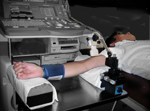
Рис. Стол и кронштейн датчика для проведения процедуры FMD от ALOKA
Пациент размещается на кушетке лёжа. Датчик фиксируется над плечевой или локтевой артериях. Манжету надевают на запястье или предплечье. После размещения пациента и фиксации датчика с выводом нужного сосуда на экране начинается сбор данных. Измеряется диаметр просвета сосуда в покое до начала исследования. Затем в манжету нагнетается воздух по давлением 200-300 мм.рт.ст. В течение 4-5 минут проиходит сжатие сосудов (окклюзия). Далее воздух из манжеты стравливается и начинается вазодилатация (расширение) сосуда. Через минуту после начала стравливания воздуха из манжеты происходит пик вазодилатации (макисмальный просвет).
Результаты исследования: базовый и пиковый диаметр просвета сосуда, %FMD.
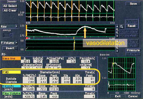
Рис. Результаты проведения FMD исследования на УЗ сканере ALOKA.
Клинические статистические данные показывают, что у людей с повышенным риском развития сердечно-сосудистых заболеваний степень вазодилатации (%FMD) ниже, чем у здоровых засчёт нарушения функции эндотелия и выработки оксида азота (NO).
Рис. CVR=0 (здоровые пациенты), CVR>0 (пациенты с риском развития сердечно-сосудистых заболеваний). Средний диаметр артерии у второй группы значительно больше, чем у первой (здоровых): 4,4±0,1 мм по сравнению с 3.8±0,1 мм у здоровых, а значение FMD меньше:
(6.36±0.47% по сравнению с 9.26±0.96% у здоровых).
Дисфункция эндотелия — первый шаг к атеросклерозу. Обнаружение на этом этапе может помочь предотвращению развития атеросклероза. Метод FMD может использоваться в качестве показателя улучшения функции эндотелия после избавления от факторов риска с помощью физических упражнений, диеты и лечения. Некоторые исследователи полагают, что показатель %FMD можно улучшить, используя лекарства от гипертензии и гиперлипидемии, эстрогены, витамин Е и витамин С.
Выводы
Все вышеобозначенные методики позволяют диагностировать атеросклероз и ишемическую болезнь сердца на ранних этапах. Однако достоверная диагностика невозможна без получения больших баз данных по пациентам и статистики для выработки оптимальных критериев. Мы призываем врачей активнее пользоваться новыми технологиями в диагностике и помогать проводить сбор статистических данных в России.
История знает замечательный пример, когда тщательный сбор статистики привёл к поразительным результатам. В 1948 году в США стартовал Фрамингемский эксперимент, в рамках которого всех жителей небольшого городка Фремингем каждый год обследовали на предмет сердечно-сосудистых заболеваний. Эксперимент продлился несколько десятков лет. Были получены ценнейшие статистические данные. В результате с 50-х годов смертность от сердечно-сосудистых заболеваний в США снизилась почти в 3 раза. Имеющаяся статистика показывает, что такой результат стал возможен в основном благодаря своевременной диагностики и правильному лечению заболеваний, нежели устранению факторов риска. В остальном же мире показатель смертности от сердечно-сосудистых заболеваний только растёт.
Список литературы и полезные материалы:
1. Мангеймское соглашение об измерении комплекса интима-медиа. Mannheim Carotid IMT Consensus 2004-2006. Статистические данные. Скачать PDF.
2. Статистические данные: что точнее — ручное или автоматическое измерение комплекса-интима медиа. Статья.
3. Техническая информация. Методы автоматического оконтуривания комплекса интима-медиа по амплитудному В-изображению. Презентация.
4. Критерии оценки метода eTracking и его индексов от ALOKA, применение в клинической практике и статистические данные. Исследовано 4800 человек (Китай). Скачать PDF.
5. Критерии оценки метода eTracking и его индексов от ALOKA, применение в клинической практике и статистические данные. Исследовано 60 человек (Италия). Скачать PDF.
6. Критерии оценки индекса CAVI от Fukuda Denshi. Исследовано 6800 человек. Сайт.
7. Сборник статей по артериальной ригидности. Индексы SI, RI, PWVcf. Скачать PDF.
8. Метод потоко-опосредованной дилатации FMD (Flow-Mediated Dilatation) от ALOKA. Критерии оценки метода, применение в клинической практике и статистические данные. Исследовано 36 человек. Скачать PDF.
9. Метод оценки интенсивности волн крови в сосудистом русле WI (Wave Intensity) от ALOKA. Критерии оценки метода, применение в клинической практике и статистические данные. Скачать PDF.
Спасибо за внимание. Купить аппараты FUJIFILM (HITACHI) с поддержкой рассматриваемых опций или дооснастить уже имеющиеся аппараты FUJIFILM (HITACHI) можно у нас в компании ООО «Рус-эксп», обратившись по телефонам (495) 972-24-18, 972-92-14 или отправив запрос на электронную почту info@rus-exp.com. Наши специалисты проведут монтаж и полноценное обучение врачей и медицинского персонала. Данное оборудование FUJIFILM (HITACHI) уже используется в крупных медицинских центрах для сбора статистики и высокоточной диагностики сосудов.
*Примечание: рассматриваемые режимы является опциями — требуется дополнительное программное обеспечение и/или блоки.
**Примечание: производитель вправе изменить технические характеристики и возможности рассматриваемых опции без уведомления.
![]()
- Главная
- Медицинская техника
- Оборудование для УЗИ

-
314401
- 0
-
Диагональ 12” (или 17 на выбор): ЖК безбликовый, подвижный, с фильтром, 256 градаций серого цвета.
-
Регистрационное удостоверение:
Да
- Показать все характеристики

Самовывоз
Самовывоз продукции осуществляется по адресу: Москва, ул. Халтуринская 6А (м. Преображенская площадь)
- Описание
- Характеристики
- Доставка и самовывоз
ALOKA ProSound 6 и ALPHA 6 (Premier) – ультразвуковые сканеры с жидкокристаллическим LCD-дисплеем, широким ассортиментом датчиков, с тканевой гармоникой и поддержкой работы в сетях по протоколу DICOM 3.0 (опционально). Несмотря на компактность и малогабаритность конструкции, даные аппараты отвечают всем стандартам качества.
- Монитор ЖК LCD 12” (LCD 17″)
- Компактная настроенная флеш-память
- Датчики, созданные по широкополосной технологии с высокой плотностью элементов Wideband Super High Density (W-SHD) – такие же, как в моделях более высоких классов.
- Динамическая фокусировка изображения
- Динамический контроль апертуры
- Динамический контроль частоты датчика в зависимости от глубины исследования
- Режим брахитерапии.
Отличие моделей. Технические характеристики у данных УЗИ-аппаратов во многом совпадают. Однако имеются некоторые отличия: увеличенная кинопамять, встроенная алфавитно-цифровая клавиатура, шумоподавление AIP, компаундинг SCI, встроенный блок ускорения для дополнительных функций.
Технические характеристики АLОКА ProSound 6 и ALPHA 6 (Premier)
| Дисплей УЗИ-сканера | Диагональ 12” (или 17 на выбор): ЖК безбликовый, подвижный, с фильтром, 256 градаций серого цвета. |
| Режимы визуализации | В-режим, В/В, В/М, М-режим, с максимальной частотой кадров 238. |
| Кинопетля | на 1300 кадра |
| Возможность дополнительного соединения с СD ROM, видеопринтером, дисплеем физиосигналов (ЭКГ синхронизированных с В режимом) | есть |
| Поддержка работы более 24 разнообразных датчиков |
|
| 17 встроенных изменяемых программ настроек визуализации | для разных видов исследований |
| Видео входы/выходы | есть |
| Тканевая гармоника | Позволяет значительно снизить помехи, которые обычно связаны с переотражением и боковыми лепестками. |
| Количество коннекторов для датчиков | 2 шт. |
| Управление данными изображений в цифровом формате |
|
| Память | 999 изображений на встроенной флеш карте |
Комплектация ультразвуковых аппаратов
- УЗИ-аппарат
- Пакет урологических вычислений, пакет акушерских и гинекологических вычислений, кардиовычисления. Имеет режим брахитерапии.
- Датчики многочастотные (до 4 несущих частот), поддержкой второй тканевой гармоники (до 4 частот).
- Поддержка работы в сетях по протоколу DICOM 3.0 (опция)
- 2 коннектора для датчиков.
- С акушерско-гинекологическими, урологическими и кардиологическими отчетами.
- Видео входы/выходы.
- Инструкция на русском языке.
- UST-9123 Конвексный датчик с частотой 2,5/3,8/5,0/6,0 МГц, радиусом 60 мм, углом обзора 60 град. для абдоминальных исследований, акушерства/гинекологии, урологии с поддержкой функции тканевой гармоники (2,1P/2,1S/2,1R/2,1H)
Датчики УЗИ-сканера ALOKA ProSound 6
Конвексные датчики:
- UST-9123 Датчик конвексный абдоминальный супервысокой проницаемости для брюшной полости, акушерства/гинекологии, В:2.8/3.8/5.0/6.0, 60гр., 60mmR, поддержкой гармонического эхо,возможностью пункционного адаптера MP-2473
- UST-9127 Датчик конвексный абдоминальный супервысокой проницаемости для брюшной полости, акушерства/гинекологии, В:2.5/3,8/5.0/6.0, 60гр., 60mmR поддержкой гармонического эхо1,9/2,1/2,5/2,5 Мгц
- UST-9102-3.5-U Датчик конвексный абдоминальный супервысокой проницаемости (интеркостальный доступ), В:3.0/3.75/5.0/6.0, 90гр., 20mmR, возможностью пункционного адаптера MP-2414C
- UST-9124 Датчик конвексный эндополостной, трансвагинальный супервысокой проницаемости, В:3.8/5.0/6.0/7.5, 180гр., 9mmR,возможностью пункционного адаптера
- UST-995-7.5 Датчик конвексный интраоперационный супервысокой проницаемости, В:5.0/6.0/7.5/10.0, 65гр., 20mmR
- UST- MC11-8731 Датчик интраоперационный пальчиковый 5,0/6,0/7,5/10,0 Мгц, углом обзора 65градусов радиусом 20мм.
- UST-987-7.5 Датчик конвексный для исследования малых органов, нейросонографии у детей супервысокой проницаемости, В:5.0/6.0/7.5/10.0, 65гр., 20mmR
- UST-676P Датчик конвексный трансректальный (end fire), В:3.8/5.0/6.0/7.5,180гр., 9mmR, пункционный с стандартной насадкой в комплекте
- UST-9133 Датчик микроконвексный секторный интеркостальный с возможностью биопсии, диаметром 20 мм,поддержкой второй гармоники,В:3,0/3,8/5,0/6,0 THE 2,1 CF 2,!/2,5/3,0/3,8, шириной 13мм , биопсийная насадка MP-2781-опция.
Линейные датчики:
- UST-5045Р-3.5 Датчик линейный пункционный/биопсийный с центральным расположением пункционного канала, супервысокой проницаемости, В:3.0/3.75/5.0/6.0, 80mm
- UST-5710-7.5 Датчик линейный для исследования малых органов супервысокой проницаемости, В:5.0/6.0/7.5/10.0, 60mm, возможностью биопсийной насадки MP-2456
- UST- 5413 Датчик линейный для исследования малых органов и сосудов поверхностно расположенных с управляемым УЗ лучем супервысокой проницаемости,поддержкой тканевой гармоники. В:5.0/6.0/7.5/10.0, 38mm
- UST-5542 Датчик электронный линейный для поверхностных тканей (мускулы, сухожилия),сосудов с управляемым УЗ лучом В/М:7.5/10.0/13.0, 29mm
Биплановый секторно/линейный датчик
- UST-672-5.0/7.5 Датчик конвексный/линейный трансректальный супервысокой проницаемости, Конвексный:120deg./9mmR, В:3.75/5.0/6.0/7.5, Линейный:60mm, В:5.0/6.0/7.5/10.0
| Характеристики | |
| Дисплей | Диагональ 12” (или 17 на выбор): ЖК безбликовый, подвижный, с фильтром, 256 градаций серого цвета. |
| Регистрационное удостоверение | Да |
ПОХОЖИЕ ТОВАРЫ
- Manuals
- Brands
- Aloka Manuals
- Medical Equipment
- ProSound Alpha 10
- Service manual
-
Contents
-
Table of Contents
-
Bookmarks
Quick Links
SERVICE MANUAL
SSD — ALPHA10
1 / 2
English Edition
Document Number : MN2-2008
Document Revision : 2
©
Copyright
FILE 1
Related Manuals for Aloka ProSound Alpha 10
Summary of Contents for Aloka ProSound Alpha 10
-
Page 1
SERVICE MANUAL SSD — ALPHA10 1 / 2 English Edition Document Number : MN2-2008 Document Revision : 2 © Copyright FILE 1… -
Page 2
MN2-2008, Rev.2 SSD-ALPHA10 SERVICE MANUAL Contents of SSD-ALPHA10 SERVICE MANUAL 1/2 PAGE Section 1 How to use this service manual page 1-1~1-4 (4 pages) Service Manual···················································································· Contents of this Service Manual ·························································· Construction of This Service Manual··················································· Contents of Each Section····································································· Section 2 PRECAUTIONS (read without fail) page 2-1~2-6 (6 pages) -
Page 3
MN2-2008, Rev.2 SSD-ALPHA10 SERVICE MANUAL Section 5 SCHEMATICS page 5-1~5-208 (208 pages) Main Body SSD-ALPHA10 CABLE CONNECTION ·········································· CABLE 001, 010, 011, 012, 013, 020, 030, 031, 032, 033 ·················· CABLE 101, 110, 111 ········································································· 5 — 18 CABLE 201 ························································································ 5 — 19 CABLE 301 ························································································… -
Page 4
IPC-1710(C) VIDEO CIRCUIT ·························································· 5 — 156 Viewing Color TV monitor IPF-1901 The schematics of IPF-1901 is not available because of NDA — non-disclosure agreement between manufacturer and ALOKA. Operation Panel L-KEY-84* Panel Control PCB EP513200C* (for L-KEY-84B*) ···················· 5 — 157 EP513200E* (for L-KEY-84C~G) ·················… -
Page 5
MN2-2008, Rev.2 SSD-ALPHA10 SERVICE MANUAL EP513300EF (for L-KEY-84G~)···················· 5 — 187 Panel Menu PCB EP513400C* (for L-KEY-84C~G) ················· 5 — 193 EP513400D* (for L-KEY-84H)······················ 5 — 197 Physio Signal display unit PEU-ALPHA10* PEU-ALPHA10* CABLE CONNECTION ········································ 5 — 201 CABLE 601, 610, 611, 612 ································································· 5 — 202 Independent probe connection unit EU-9110 CABLE 900 ························································································… -
Page 6: Mn2-2008,
MN2-2008, Rev.2 SSD-ALPHA10 SERVICE MANUAL Contents of SSD-ALPHA10 SERVICE MANUAL 2/2 Section 6 TROUBLE SHOOTING Section 7 ADJUSTMENT PROCEDURE Section 8 PERFORMANCE CHECK Section 9 DISASSEMBLING PROCEDURE Section 10 PARTS LIST Section 11 SERVICE INFORMATION Appendix SSD-ALPHA10 SERVICE MANUAL Appendix 5 / 6…
-
Page 7
MN2-2008, Rev.2 SSD-ALPHA10 SERVICE MANUAL (Blank page) 6 / 6… -
Page 8
SECTION 1 How to use this service manual SECTION 1… -
Page 9
MN2-2008 SECTION 1 How to use this service manual Service Manual This service manual has been prepared for persons in charge of repair at the field. This service manual is compiled according to the following basic principle. ”For service, pick out a faulty PCB and replace it with a new PCB.”… -
Page 10
MN2-2008 SECTION 1 How to use this service manual Contents of Each Section SECTION 1 How to use this service manual Describes the purpose of the Service Manual. SECTION 2 PRECAUTIONS Describes general precautions and preparations for maintenance service. Be sure to follow working procedures if mentioned. -
Page 11
MN2-2008 SECTION 1 How to use this service manual SECTION 11 SERVICE INFORMATION Provides available information about maintenance service. APPENDIX SERVICE MANUAL Appendix Manual change information, the revision list of this manual, is filed in this section. 1 — 3… -
Page 12
MN2-2008 SECTION 1 How to use this service manual (Blank page) 1 — 4… -
Page 13
SECTION 2 PRECAUTIONS SECTION 2… -
Page 14
MN2-2008 SECTION 2 PRECAUTIONS 2-1 Precautions Against Electrical Hazards to Serviceman When disassembling the equipment after checking it for a trouble symptom, give care to the following: Be sure to unplug the equipment before disassembly. Be sure to turn off the main switch on the equipment when removing electrical parts such as PCBs, probe, and cable. -
Page 15
MN2-2008 SECTION 2 PRECAUTIONS 2-4 Precautions for Keeping Electrical Safety Be sure to ground the equipment securely. Perfectness in grounding, screw tightening, and cover installation is essential. Negligence of it could cause a possibility of leakage current from outer fitting which may lead to serious damage to a patient being diagnosed. -
Page 16
MN2-2008 SECTION 2 PRECAUTIONS 2-8 Care to be Taken in the Field Check for trouble symptoms. Check for connection to optional devices and other peripheral devices. Record the contents of the battery backup memory. After working, restore the equipment according to the above mentioned contents of memory if necessary. -
Page 17
Handling of S.M.D. PCBs 2-10 It is an Aloka’s policy that neither repair nor modification of PCBs used for S.M.D. is made in the field as a rule because of the following reasons: [REMARKS] PCB does not need repairing or modifying in the field as a rule. -
Page 18
MN2-2008, Rev.2 SECTION 2 PRECAUTIONS System Symbols 2-11 Symbols used by Aloka are described below, together with reference to IEC publication(s). Symbol Position Meaning Danger Carefully read the pertinent items in the operation manual, and handle the equipment with grate care. -
Page 19
MN2-2008, Rev.2 SECTION 2 PRECAUTIONS Symbol Position Meaning Potential equalization terminal Rear panel IEC60417-5021 Protected against the effects of continuance immersion Foot switch in water MP-2345B MP-2614B IEC60529 Electrostatic discharge (ESD) symbol A symbol warning of no touching to the pins cropping Various places out. -
Page 20
SECTION 3 Before Repairing SECTION 3… -
Page 21
MN2-2008 SECTION 3 Before Repairing Repair work on the description of Service Manual The typical processes for the repair work are shown as the Flow Chart on the next page. Do the repair work according to this procedure. In the case of modification of the Technical Bulletin, Technical Notes or Upgrade Kit, see the next item 3-2. -
Page 22
MN2-2008 SECTION 3 Before Repairing Demand of repair (START) Reception and Technical Bulletin, Technical Notes Investigation Section 4~6, 11 Section 6, 10 Selection and order of Required part(s) History Preparation Section 3 At your site At Customer side Confirmation Repair and Section 2, 6, 9 adjustment Operation check… -
Page 23
MN2-2008 SECTION 3 Before Repairing Procedure 1 Reception of repair and investigation Accept the repair request from the customer or distributor. At this time, the following points have to be confirmed and checked, Model name/number, and serial number Name of customer (Hospital), address, phone number, and name of person in charge Configuration of the connection of peripheral devices Software version or the like shown on the Maintenance display (if possible) Detail of phenomenon appeared on the function of equipment… -
Page 24
MN2-2008 SECTION 3 Before Repairing Procedure 3 Preparation of visiting the customer Check the required tools, measuring devices and parts to be replaced before the visiting the customer. Then check the special information for the equipment reference with the following section, Section 3 BEFORE REPAIRING… -
Page 25
MN2-2008 SECTION 3 Before Repairing Procedure 7 Judgment of the operation quality If the result of “Procedure 6” is passed to the all standards, do the next “Procedure 8”. On the other side, if not, make a judgment of “Procedure 10”. Procedure 8 Confirm by customer, make repair report and approve Reconfirm the solution of trouble phenomenon with the customer. -
Page 26
MN2-2008 SECTION 3 Before Repairing Upgrade work on the description of Service Manual The typical processes for the upgrade work are shown as the Flow Chart on the next page. Do the upgrade work according to this procedure. In the case of repair work, see the previous item 3-1. Each procedures of flow chart are numbered to refer its detail shown from page 3-8. -
Page 27
MN2-2008 SECTION 3 Before Repairing Demand of upgrade (START) Technical Bulletin Selection and order of Consultation with Technical Notes requires parts/kits Technical Support Installation Procedure Section 3 Preparation At your site At customer site Section 8 Operation check Work as normal? Do the repair work, according to item 3-1 Upgrade… -
Page 28
MN2-2008 SECTION 3 Before Repairing Procedure 1 Selection of required parts / kits and order Accept the upgrade request from the customer, distributor or person in charge of sales. At this time, the following points have to be confirmed and checked to decide the parts and kits, Document name that announced the upgrade or kit requested Model name/number, and serial number Name of customer (Hospital), address, phone number, and name of person in charge… -
Page 29
MN2-2008 SECTION 3 Before Repairing Procedure 3 Operation check before upgrade On the basis of work, the upgrade to the defective equipment is prohibited. Because, before upgrade work, check the behavior of equipment whether normal or not according to following section and document, Section 8 PERFORMANCE CHECK… -
Page 30
MN2-2008 SECTION 3 Before Repairing Procedure 8 Confirmation by customer Reconfirm any functions of equipment with the customer. Then, if need, introduce and explain about the new functions and specification added by this upgrade. Furthermore, if need, make a report to be approved by the customer. The report shows not only the treatment but also the method of operation check. -
Page 31
MN2-2008 SECTION 3 Before Repairing Procedure 12 Indication of the prohibition to use As the result of judgment on “Procedure 11”, if you judge that it is impossible to recover at this time, indicate that the equipment is the out of order, and also show the prohibition to use, on the equipment. -
Page 32
MN2-2008 SECTION 3 Before Repairing (Blank page) 3 — 12… -
Page 33
SECTION 4 PRINCIPLE OF SYSTEM OPERATION SECTION 4… -
Page 34
MN2-2008, Rev.2 SECTION 4 Principle of System Operation System Specification Notes about expression: The comments like “Ver.2~” in this document generally means the level of system in combination of software and hardware. Therefore, some of specification below may not be applied if only the software is compatible. -
Page 35
MN2-2008, Rev.2 SECTION 4 Principle of System Operation Display modes Electronic 3D Phased Mechanical Mechanical Electronic 3D Convex Independent Linear/ Array Sector Radial Sector Sector Convex Sector B, B-Zoom, 2B B (F), B (PF), B(F)-Zoom, B(PF)-Zoom 2B(F), 2B(PF) 4B(F), 4B(PF) 4B, B/M (*1) B(F)/M(F) -
Page 36
MN2-2008, Rev.2 SECTION 4 Principle of System Operation Transmission Method Electronic Probes Compound Pulse Wave transmission (Maximum number of burst wave is 8 waves) Transmission Apodalization Real-time transmission voltage control Ver.4.1~ Active CW transmission crystal is changed alternatively time by time (specific probe only) Mechanical Probes Ver.4.0~ Single transmission… -
Page 37
MN2-2008, Rev.2 SECTION 4 Principle of System Operation Image Quality Adjustment B Gain ~Ver.5 30~90dB (60/256 dB Step) Ver.6.0~ 10~90dB (40/256 dB Step) Possible on both real time and frozen image. M Gain ±30dB (60/256 dB Step) from B Gain Settings Possible on both real time and frozen image. -
Page 38
MN2-2008, Rev.2 SECTION 4 Principle of System Operation Spectral Doppler Applicable probe PW: Electrical linear/convex/sector CW: Electrical sector Frequency Analysis System FFT system Display Power spectrum Frequencies PW Doppler ..1.88, 2.14, 2.5, 3, 3.75, 5, 6, 7.5 MHz CW Doppler..1.88, 2.14, 3.75 MHz Analysis rate (Velocity Range) There are limits depending on the probe frequency PW Doppler:… -
Page 39
MN2-2008, Rev.2 SECTION 4 Principle of System Operation Color Flow Frequency Estimation System Auto-correlation method Display Velocity Variance Velocity/Variance Power Flow Directional Power Flow Ver.2.1~ eFlow (For Lite version, the SOP-ALPHA10-4 is required) Ver.2.1~ Tissue Doppler Image Ver.3.0~ BETA(TDI Power) Ver.4.0~ Directional eFlow (For Lite version, the SOP-ALPHA10-4 is required) -
Page 40
MN2-2008, Rev.2 SECTION 4 Principle of System Operation Image Gradation B/W: 8bit, 256 steps Velocity: 8bit, ±127 steps Variance: 4bit, 16 steps Power Flow: 7bit, 128 steps Displayable Scanning Lines Max 1024 lines Display Memory B/W: 1024 × 512 × 8 bit × 2 planes Velocity/Power: 1024 ×… -
Page 41
Multi-image output format (the SOP-ALPHA10-2 is required) Video Clip DICOM JPEG Ver.4~ Real-time video clip acquiring Ver.6~ Non-interlaced multi frame image Ver.7~ Re-capturing with single frame MS-MPEG4 Codec Motion JPEG Codec (Ver.7~) Line ALOKA private Ver.5~ Re-capturing specified loop 4 — 8… -
Page 42
MN2-2008, Rev.2 SECTION 4 Principle of System Operation Ver.5~ Re-capturing with Video clip format Ver.5~ Re-capturing single frame with measurement result Ver.5~ Convert Line data to DICOM multi-frame Ver.7~ Possible to adjust image parameter at playback the data Backup Media DICOM Server/Printer (the SOP-ALPHA10-10 is required) ~M01530 HDD, MO, CD-R, FD… -
Page 43
MN2-2008, Rev.2 SECTION 4 Principle of System Operation Display information Language English Auto Display date, time, Imaging frequency (Ver.7~: Reception frequency for harmonic), Image Direction mark, diagnostic distance, Gain, Contrast, Frame Rate, Transmission voltage (% display), Focus Mark, Velocity Range, Heart Rate (Ver.7~: Stabile heart rate display), R-Delay, BSA/GW/PSA, Maximum Velocity, Velocity Scale, Doppler Angle correction, Preset Name, Acoustic Power MI, TI , Timer display, Study time display… -
Page 44
MN2-2008, Rev.2 SECTION 4 Principle of System Operation transcribe function) Ver.3~: Flow Volume (VTI) B(Flow) mode Basic Measurement Blood flow measurement (Flow Profile) (the SOP-ALPHA10-7 is required) Obstetrical Measurements B mode GA measurement (gestational week, Ver.4~: Automatic calculation of AC, HC, FTA, AD and AXT), FW measurement (Fetus Weight), Fetus Ratio measurement, Amniotic Fluid Index, Cardio Thoracic Area Ratio, Cervix… -
Page 45
MN2-2008, Rev.2 SECTION 4 Principle of System Operation measurement, Pulmonary vein flow measurement Ver.2.1~: Coronary measurement Ver.6~: CRT(Asynchrony) measurement B(f)/D mode PISA measurement Ver.3~ Power mode BETA measurement TDI M mode M TDI measurement Ver.3~: midwall FS measurement, M TDI WT(LVPW), (IVS) measurement TDI PW mode TDI PW measurement Abdominal Measurements B mode… -
Page 46
MN2-2008, Rev.2 SECTION 4 Principle of System Operation Addition of function to avoid R-wave (Ver.7~) Addition of R-wave polarity reversal function (Ver.7~) Addition of wave form of primary derivation (Ver.7~) Addition of setup method for manual AI value (Ver.7~) Addition of raw data output (Ver.7~) Ver.3~ BETA(Backscattered Energy Temoral Analysis) Ver.4~… -
Page 47
MN2-2008, Rev.2 SECTION 4 Principle of System Operation Input-Output Signal Digital data Input-Output USB2.0 × 6ch RS-232C For ALK-3 communication 1 System IEEE1394 For DV video output 1 System (Option: M00951~, the PM-A10-H006 and PM-A10-H007 are required) Analog video Input-Output Composite output for B/W video printer 1 System Control signal (PRINT/BUSY) -
Page 48
MN2-2008, Rev.2 SECTION 4 Principle of System Operation Dimensions 580mm (W), 1095 ~ 1190mm(D), CRT model: 1440 ~ 1570mm(H) LCD model: 1460 ~ 1650mm(H) Weight Approx. 210kg (Standard Configuration) Approx. 203kg (Ver.5~ Standard Configuration) Classification for the protection against surges Class 1 Device Classification for the degree of protection against surges BF type… -
Page 49
MN2-2008, Rev.2 SECTION 4 Principle of System Operation Major Options Photographic Equipment B/W Video Printer (Analog) UP-895MD / UP-895CE / UP-895MD/SYN UP-897MD / UP-897CE / UP-897MD/SYN P93 / P93W / P93E B/W Video Printer (Digital) Ver.3~ UP-D897 Ver.6~ P93D / P93DW Color Video Printer (Analog) UP-21MD / UP-21MD(CED) CP900 / CP900UM / CP900E… -
Page 50: Storage Drive Unit
MN2-2008, Rev.2 SECTION 4 Principle of System Operation System Configuration This ultrasound diagnostic machine (SSD-ALPHA10) consists of those units below Main body PSC-138* USM-28* Tx/Rx part Digital Beam Former part Flow/Doppler part DIU part Operation Panel L-KEY-84* Viewing monitor IPC-1710* (CRT type, ~M01590) IPF-1901 (LCD type, M01591~) Power supply unit PSU-ALPHA10…
-
Page 51
PM-A10-H006, PM-A10-H007 and R RS-232C straight cable 9pin (Female, inch-scale-screw) – 25pin (Female, mm-scale-screw) are required ALOKA DV-800 ~M00950: PM-A10-H001 or PM-A10-H001B is required * Both DV-800 and LCD monitor are not available simultaneously. M00951~: PM-A10-H006 and PM-A10-H009 or PM-A10-H009B are required DV-800(B), Ver.6~… -
Page 52
MN2-2008, Rev.2 SECTION 4 Principle of System Operation Software option package Extended Filed of View SOP-ALPHA10-1 * For Lite version, the EU-9102 is required Motion JPEG SOP-ALPHA10-2 * For Lite version, the EU-9102 is required Real Time Doppler Auto Trace SOP-ALPHA10-3 Real Time 3D SOP-ALPHA10-4… -
Page 53
MN2-2008, Rev.2 SECTION 4 Principle of System Operation Flow 3D SOP-ALPHA10-35 (Ver.7.0~) * the SOP-ALPHA10-4 is required. * For Lite version, the EU-9102 isrequired. * For S/N M01870 and before, the PM-A10-H013 is required. System Block Diagram There are the lists of all PCB (Except Power supply unit and external peripherals) and the system block diagram mentioned from the next page. -
Page 54
MN2-2008, Rev.2 SECTION 4 Principle of System Operation 4 — 21… -
Page 55
MN2-2008, Rev.2 SECTION 4 Principle of System Operation 4 — 22… -
Page 56
MN2-2008, Rev.2 SECTION 4 Principle of System Operation 4 — 23… -
Page 57
MN2-2008, Rev.2 SECTION 4 Principle of System Operation (Blank page) 4 — 24… -
Page 58
MN2-2008, Rev.2 SECTION 4 Principle of System Operation CD-RW MODrive Foot SW (Option) USB/ATA Foot SW Converter EU-9098 RS232C IEEE1284 USI-153 Sector or Linear or PSC-138 Convex Probe WAVE GEN.1-3 F.E. Cont CPU I/O Tx wave PROBE SEL STC Seq. Main Panel Assembly Local Mecha… -
Page 59
MN2-2008, Rev.2 SECTION 4 Principle of System Operation (Blank Page) 4 — 26… -
Page 60
MN2-2008, Rev.2 SECTION 4 Principle of System Operation 4 — 27… -
Page 61
MN2-2008, Rev.2 SECTION 4 Principle of System Operation 4 — 28… -
Page 62
MN2-2008, Rev.2 SECTION 4 Principle of System Operation 4 — 29… -
Page 63
MN2-2008, Rev.2 SECTION 4 Principle of System Operation (Blank page) 4 — 30… -
Page 64
MN2-2008, Rev.2 SECTION 4 Principle of System Operation Digital CD-RW MODrive Printer(Option) Foot SW (Option) USB/ATA Foot SW Converter EU-9098 Sector or Linear or Convex Probe USI-153 PSC-138 IEEE1284 RS232C WAVE GEN.1-3 F.E. Cont Tx wave CPU I/O PROBE SEL STC Seq. -
Page 65
MN2-2008, Rev.2 SECTION 4 Principle of System Operation (Blank Page) 4 — 32… -
Page 66
MN2-2008, Rev.2 SECTION 4 Principle of System Operation 4 — 33… -
Page 67
MN2-2008, Rev.2 SECTION 4 Principle of System Operation 4 — 34… -
Page 68
MN2-2008, Rev.2 SECTION 4 Principle of System Operation 4 — 35… -
Page 69
MN2-2008, Rev.2 SECTION 4 Principle of System Operation (Blank page) 4 — 36… -
Page 70
MN2-2008, Rev.2 SECTION 4 Principle of System Operation Digital CD-RW MODrive Printer(Option) Fo o t SW (O p t io n ) USB/ATA Foot SW Converter EU-9098 Sector or Linear or Convex Probe USI-153 PSC-138 IE EE1284 RS232C LA N WAVE GEN.1-3 F.E. -
Page 71
MN2-2008, Rev.2 SECTION 4 Principle of System Operation (Blank Page) 4 — 38… -
Page 72
MN2-2008, Rev.2 SECTION 4 Principle of System Operation 4 — 39… -
Page 73
MN2-2008, Rev.2 SECTION 4 Principle of System Operation 4 — 40… -
Page 74
MN2-2008, Rev.2 SECTION 4 Principle of System Operation 4 — 41… -
Page 75
MN2-2008, Rev.2 SECTION 4 Principle of System Operation (Blank page) 4 — 42… -
Page 76
MN2-2008, Rev.2 SECTION 4 Principle of System Operation Digital CD-RW MODrive Printer(Option) Fo o t SW (O p t io n ) USB/ATA Foot SW Converter EU-9098* Sector or Linear or JB-284(Option) Convex Probe USI-153 PSC-138 I EEE1284 RS232C LA N M ain P an el Assem bly L-KEY-84* WAVE GEN.1-3… -
Page 77
MN2-2008, Rev.2 SECTION 4 Principle of System Operation (Blank Page) 4 — 44… -
Page 78
MN2-2008, Rev.2 SECTION 4 Principle of System Operation 4 — 45… -
Page 79
MN2-2008, Rev.2 SECTION 4 Principle of System Operation 4 — 46… -
Page 80
MN2-2008, Rev.2 SECTION 4 Principle of System Operation 4 — 47… -
Page 81
MN2-2008, Rev.2 SECTION 4 Principle of System Operation (Blank page) 4 — 48… -
Page 82
MN2-2008, Rev.2 SECTION 4 Principle of System Operation Digital CD-RW MODrive Printer(Option) Fo o t SW (O p t io n ) USB/ATA Foot SW Converter EU-9098* Sector or Linear or JB-284(Option) Convex Probe USI-153 PSC-138 IE EE1284 RS232C LA N M ain P an el A ssem bly L-KEY-84* WAVE GEN.1-3… -
Page 83
MN2-2008, Rev.2 SECTION 4 Principle of System Operation (Blank Page) 4 — 50… -
Page 84
MN2-2008, Rev.2 SECTION 4 Principle of System Operation 4 — 51… -
Page 85
MN2-2008, Rev.2 SECTION 4 Principle of System Operation 4 — 52… -
Page 86
MN2-2008, Rev.2 SECTION 4 Principle of System Operation 4 — 53… -
Page 87
MN2-2008, Rev.2 SECTION 4 Principle of System Operation (Blank page) 4 — 54… -
Page 88
MN2-2008, Rev.2 SECTION 4 Principle of System Operation Digital CD-RW MODrive Printer(Option) Fo o t SW (O p t io n ) USB/ATA Foot SW Converter EU-9098* Sector or Linear or JB-284(Option) Convex Probe USI-153 PSC-138 I EE E1284 RS232C LA N M ain P an el A ssem bly L-KEY-84*… -
Page 89
MN2-2008, Rev.2 SECTION 4 Principle of System Operation (Blank Page) 4 — 56… -
Page 90
MN2-2008, Rev.2 SECTION 4 Principle of System Operation 4 — 57… -
Page 91
MN2-2008, Rev.2 SECTION 4 Principle of System Operation 4 — 58… -
Page 92
MN2-2008, Rev.2 SECTION 4 Principle of System Operation 4 — 59… -
Page 93
MN2-2008, Rev.2 SECTION 4 Principle of System Operation (Blank page) 4 — 60… -
Page 94
MN2-2008, Rev.2 SECTION 4 Principle of System Operation Digital DVD-RAM Printer(Option) Fo o t SW (O p t io n ) ATA-USB Converter Foot SW -HUB EU-9098* Sector or Linear or JB-284(Option) Convex Probe USI-153 PSC-138 I EE E1284 RS232C LA N M ain P an el A ssem bly L-KEY-84*… -
Page 95
MN2-2008, Rev.2 SECTION 4 Principle of System Operation (Blank Page) 4 — 62… -
Page 96
MN2-2008, Rev.2 SECTION 4 Principle of System Operation 4 — 63… -
Page 97
MN2-2008, Rev.2 SECTION 4 Principle of System Operation 4 — 64… -
Page 98
MN2-2008, Rev.2 SECTION 4 Principle of System Operation 4 — 65… -
Page 99
MN2-2008, Rev.2 SECTION 4 Principle of System Operation (Blank page) 4 — 66… -
Page 100
MN2-2008, Rev.2 SECTION 4 Principle of System Operation Digital DVD-RAM Printer(Option) Fo o t SW (O p t io n ) ATA-USB Converter Foot SW -HUB EU-9098* Sector or Linear or JB-284(Option) Convex Probe USI-153 PSC-138 I EE E1284 RS232C LA N M ain P an el A ssem bly L-KEY-84*… -
Page 101
MN2-2008, Rev.2 (DRAFT) SECTION 4 Principle of System Operation (Blank Page) 4 — 68… -
Page 102
MN2-2008, Rev.2 SECTION 4 Principle of System Operation 4 — 69… -
Page 103
MN2-2008, Rev.2 SECTION 4 Principle of System Operation 4 — 70… -
Page 104
MN2-2008, Rev.2 SECTION 4 Principle of System Operation 4 — 71… -
Page 105
MN2-2008, Rev.2 SECTION 4 Principle of System Operation (Blank page) 4 — 72… -
Page 106
MN2-2008, Rev.2 SECTION 4 Principle of System Operation Digital DVD-RAM Printer(Option) Fo o t SW (Op t io n ) ATA-USB Converter Foot SW -HUB EU-9098* Sector or Linear or JB-284(Option) Convex Probe USI-153 PSC-138 I EEE 1284 RS232C LA N M ain P an el Assem bly L-KEY-84* WAVE GEN.1-3… -
Page 107
MN2-2008, Rev.2 SECTION 4 Principle of System Operation (Blank Page) 4 — 74… -
Page 108
MN2-2008, Rev.2 SECTION 4 Principle of System Operation Principle of System Operation System Control 4-4-1 CPU board This CPU board controls entire operation of the system. This is generic computer and it controls the HDD, the disk drives and the display of LCD. It also communicates with PC boards in the machine via PCI BUS and the Operation Panel via USB. -
Page 109
MN2-2008, Rev.2 SECTION 4 Principle of System Operation Main Panel: L-KEY-84* (Operation Panel) Main Panel reads the status of switches, potentiometers, full keyboard and trackball then communicates with the CPU via USB. Main Panel includes the 8.4 inches SVGA colour LCD with touch screen as well. The video is displayed directly from the CPU and the status of LCD panel (Touch screen and encoders) is transferred to the CPU with other panel information by serial communication. -
Page 110
MN2-2008, Rev.2 SECTION 4 Principle of System Operation 4 — 77… -
Page 111
MN2-2008, Rev.2 SECTION 4 Principle of System Operation 4 — 78… -
Page 112
MN2-2008, Rev.2 SECTION 4 Principle of System Operation 4 — 79… -
Page 113
MN2-2008, Rev.2 SECTION 4 Principle of System Operation (Blank Page) 4 — 80… -
Page 114
MN2-2008, Rev.2 SECTION 4 Principle of System Operation Tx/Rx unit 4-4-2 Tx/Rx unit consists of; Probe Connector part Tx/Rx part Digital Beam Former part Beam Processor part In addition, the following module/unit are installed in Tx/Rx unit. Independent probe connection unit: EU-9110 (Option, Ver.3.0.0. -
Page 115
MN2-2008, Rev.2 SECTION 4 Principle of System Operation Digital Beam Former part The reception signal (analog) passed from TGC Amp. is converted to digital signal. Then the signal for each channel is delayed in accordance with the Rx focus data and added into an ultrasound beam. -
Page 116
MN2-2008, Rev.2 SECTION 4 Principle of System Operation Beam Processor part Beam Processor part contains Beam Processor 1 and Beam Processor 2. Beam Processor 1 is for processing of B/W echo, analyzing PW/CW Doppler signal, processing of eTracking (Ver.3~) and the interface of physiological signal. Beam Processor 2 is for color flow calculation. -
Page 117
MN2-2008, Rev.2 SECTION 4 Principle of System Operation (Blank Page) 4 — 84… -
Page 118
MN2-2008, Rev.2 SECTION 4 Principle of System Operation SSD-ALPHA10 Ver.2~Ver.3 (~M00300) 4 — 85… -
Page 119
MN2-2008, Rev.2 SECTION 4 Principle of System Operation SSD-ALPHA10 Ver.3~Ver.5 (M00301~M01050) 4 — 86… -
Page 120
MN2-2008, Rev.2 SECTION 4 Principle of System Operation SSD-ALPHA10 Ver.5~ (M01051~M01240) 4 — 87… -
Page 121
MN2-2008, Rev.2 SECTION 4 Principle of System Operation SSD-ALPHA10 Ver.6 (M01241~M01705) 4 — 88… -
Page 122
MN2-2008, Rev.2 SECTION 4 Principle of System Operation SSD-ALPHA10 Ver.6~Ver.7 (M01706~) 4 — 89… -
Page 123
MN2-2008, Rev.2 SECTION 4 Principle of System Operation (Blank Page) 4 — 90… -
Page 124
MN2-2008, Rev.2 SECTION 4 Principle of System Operation Digital Imaging Unit 4-4-3 Digital Imaging Unit consists of the following parts; CPU part which controls whole ultrasound diagnostic equipment Mass memory part which stores Ultrasound information Scan converter part which converts Ultrasound information into SVGA signal in order to display Viewing monitor Interface circuit with the peripheral equipment And this parts has the following features;… -
Page 125
MN2-2008, Rev.2 SECTION 4 Principle of System Operation Mass Memory part Mass memory has the capacity of 65,536 (524,288 on Ver.3 and later) records (lines) for B/W, Velocity, Variance and Property respectively and 458,752 (1,835,008 on Ver.3 and later) records (lines) for Graphic data such as physiological data. In the case of Stress scan, Mass memory has the capacity of 1,048,576 records (lines) by using mass memory for both B/W and color. -
Page 126
MN2-2008, Rev.2 SECTION 4 Principle of System Operation On following display mode, the parameter of 2 dimensional interpolation changes to 16 points from 4 points. — eFlow (ver.2.1~), Power CHE (Ver.4.0~), B/W (Ver.4.1~) 2 Dimensional Interpolation (with 16 points) Data from Video Memory is read out in TV scan direction, then sent to Post Process part. Post Process part (Video Process part) The signal passes through the addition of Gray scale bar / Color bar / VCR counter display / heart mark, and decision of display priority, B/W enhancement and Color coding from… -
Page 127
MN2-2008, Rev.2 SECTION 4 Principle of System Operation (Blank Page) 4 — 94… -
Page 128
MN2-2008, Rev.2 SECTION 4 Principle of System Operation SSD-ALPHA10 Ver.2 (~M00200) 4 — 95… -
Page 129
MN2-2008, Rev.2 SECTION 4 Principle of System Operation SSD-ALPHA10 Ver.2~Ver.5 (M00201~M00950) 4 — 96… -
Page 130
MN2-2008, Rev.2 SECTION 4 Principle of System Operation SSD-ALPHA10 Ver.5~Ver.6 (M00951~M01590) 4 — 97… -
Page 131
MN2-2008, Rev.2 SECTION 4 Principle of System Operation SSD-ALPHA10 Ver.6~ (M01591~) 4 — 98… -
Page 132
MN2-2008, Rev.2 SECTION 4 Principle of System Operation Physiological Signal Display unit PEU-ALPHA10* 4-4-4 Physio. Signal display unit consists of Amplifier part for physiological signal and A/D convert part (Physio. Amp board) Each physiological signal amplifies and converts from analog signal to digital signal on the Physio amp board. -
Page 133
MN2-2008, Rev.2 SECTION 4 Principle of System Operation Power Supply unit PSU-ALPHA10 4-4-5 The power supply unit is consists of Main-power supply unit (EU-6030*) to generated low-voltage, Sub-Power supply unit (EU-6031*) to generated high-voltage and provides various kinds of voltage that are required by main unit. It also provides the isolated power to the peripherals (Recorders). -
Page 134
MN2-2008, Rev.2 SECTION 4 Principle of System Operation For the fuse location, refer to the circuit diagram. Power Supply unit PSU-ALPHA10 Block diagram (M00951 and after) In addition, the power on/off sequence is controlled by MPU on the Power I/O board follows; Power On sequence 1) When you turn on only the breaker switch, +5VSB and Ac output for DVD are outputted. -
Page 135
MN2-2008, Rev.2 SECTION 4 Principle of System Operation 3) After the MPU detect shutdown completion information, the MPU send the power-off signal to the power supply unit. Then turn SSD-ALPHA10’s power off except +5VSB and AC output for DVD. In addition, MPU has the function to send the power-off signal to the power supply unit after defined time, even if the CPU (Operation System) does not shutdown fro whatever reason. -
Page 136
MN2-2008, Rev.2 SSD-ALPHA10 SERVICE MANUAL Contents of SSD-ALPHA10 SERVICE MANUAL 2/2 PAGE Section 6 TROUBLE SHOOTING page 6-1~6-2 (2 pages) Introduction ························································································· Section 7 ADJUSTMENT PROCEDURE page 7-1~7-2 (2 pages) Introduction ························································································· Section 8 PERFORMANCE CHECK page 8-1~8-20 (20 pages) Introduction ·························································································… -
Page 137
MN2-2008, Rev.2 SSD-ALPHA10 SERVICE MANUAL Contents of SSD-ALPHA10 SERVICE MANUAL 1/2 Section 1 How to use this service manual Section 2 PRECAUTIONS Section 3 BEFORE REPAIRING Section 4 PRINCIPLE OF SYTSTEM OPERATION Section 5 SCHEMATICS 2 / 2… -
Page 138: Troubleshooting
SECTION 6 TROUBLESHOOTING SECTION 6…
-
Page 139
MN2-2008 SECTION 6 Troubleshooting Introduction In this revision of the service manual, there is no description on this section. 6 — 1… -
Page 140
MN2-2008 SECTION 6 Troubleshooting (Blank page) 6 — 2… -
Page 141
SECTION 7 ADJUSTMENT PROCEDURE SECTION 7… -
Page 142
MN2-2008 SECTION 7 Adjustment Procedure Introduction SSD-ALPHA10 is fully digitized machine, so there is no part requires to be adjusted at the field. 7 — 1… -
Page 143
MN2-2008 SECTION 7 Adjustment Procedure (Blank page) 7 — 2… -
Page 144
SECTION 8 PERFORMANCE CHECK SECTION 8… -
Page 145
MN2-2008 Rev.1 SECTION 8 Performance Check Introduction Performance Check” describes the items to be confirmed for the maintenance of an equipment quality and safety under the circumstances referred to below. Once a repair work has been done, Once an improvement, for a problem or the like, has been made, Once a change as to upgrade the functions and/or specifications has been made, When a periodic inspection is made. -
Page 146
MN2-2008 Rev.1 SECTION 8 Performance Check Performance Check Those items which are covered by a performance check vary, in principle, with what is done for the operation requiring the check. In accordance with the chart given below, identify an item or items required (those marked with in the chart). -
Page 147
MN2-2008 Rev.1 SECTION 8 Performance Check 8-4-1 Functional check Using the operation panel of the equipment, you can check the operative condition of the function corresponding to each panel switch. 1) Checking the panel switch operation When any PCB around the panel or any switch on the panel is replaced, particularly check the condition of the key top (cap). -
Page 148
MN2-2008 Rev.1 SECTION 8 Performance Check ZOOM When you select the ZOOM switch in B mode and turn the rotary encoder, the image must be reduced or magnified (CW: Magnify, CCW: Reduce). The position must be moved (vertically, horizontally) with the trackball. CURSOR/B.L.S The cursor must be displayed when you select the CURSOR/B.L.S. -
Page 149
MN2-2008 Rev.1 SECTION 8 Performance Check 3) Image adjusting function The following functions must operate normally. B-GAIN In B/M mode, both gains must be adjusted by turning the GAIN control knob (CW: Increase, CCW: Decrease). The GAIN display must change from 30 to 90. * The gain display for M-mode is depend on preset setting of GAIN(M). -
Page 150
MN2-2008 Rev.1 SECTION 8 Performance Check FLOW FILTER (Freeze OFF) In the B/Flow mode, the flow filter for the flow image must be adjusted by Filter(Flow) on the LCD touch panel. FRAME RATE ACCELERATOR (Freeze OFF) In the B/Flow mode, the link between frames of Flow image must change by setting Frame Rate Acceleration to ON. -
Page 151
MN2-2008 Rev.1 SECTION 8 Performance Check 4) FUNCTION The following functions must operate normally. PROBE The kinds, model names or probe connector number of all the probes connected must be displayed correctly on the LCD touch panel. The image selected probe is displayed correctly without missing echo and unnecessary noise. -
Page 152
MN2-2008 Rev.1 SECTION 8 Performance Check CD-R drive Any images must be copied to CD-R from Review screen. And copied images must be displayed on review screen. USB flash memory (OPTION: With the JB-284 connected) The preset data must be copied to USB flash memory from Preset Control Screen. And the preset data must be restored from USB flash memory. -
Page 153
MN2-2008 Rev.1 SECTION 8 Performance Check image missing. The image printed by the color printer must be free of tint and color misalignment. 10) VCR (OPTION: With the SVO-9500MD(P)2 or HV-MD3000*(2) connected) Before performing the following checks, check that the VCR is connected properly. External input An external input image from the VCR must be output to the monitor with the EXT switch. -
Page 154
MN2-2008 Rev.1 SECTION 8 Performance Check 13) Physiological signal display unit (OPTION: With the PEU-ALPHA10* connected) Connect the ECG cable with a human body or simulator, then connect to the physiological signal display unit. Connect the PCG cable and Pulse cable, then perform the following check operations. -
Page 155
MN2-2008 Rev.1 SECTION 8 Performance Check 15) Independent probe connection unit (OPTION: With the EU-9110 connected) Before making the following checks, check that the Independent probe connection unit is installed and Independent probe is connected properly. PROBE After selecting the PROBE 6 on the LCD touch panel, CW mode image must be displayed normally. -
Page 156
MN2-2008 Rev.1 SECTION 8 Performance Check 8-4-2 Image Quality Check To ensure the quality of ultrasound images, check should be made by using a test piece or a similar object. 1) Image Quality TOTAL IMAGE QUALITY Condition: B mode, GAIN set to proper level, STC at center, CONTRAST 4 A proper image must be shown with the probe placed on the abdominal and cardiac region. -
Page 157
MN2-2008 Rev.1 SECTION 8 Performance Check COIN CHECK (Only for UST-5411) Confirm that the focus points change smoothly for elevation direction on UST-5411. Apply a thin film of jelly to the probe, put a thin piece of metal on the center of the probe surface (See “Fig. -
Page 158
MN2-2008 Rev.1 SECTION 8 Performance Check 2) Total Performance test Condition: Probe UST-9130 or UST-52101 Total Sensitivity Use a test phantom, RMI MODEL 403GS or an equivalent, confirm the following items on B mode. A reflection echo of the seventh vertical Nylon pin can be shown. Actual Echo of deeper than 11 cm can be seen. -
Page 159
MN2-2008 Rev.1 SECTION 8 Performance Check Distance accuracy Use a test phantom, RMI MODEL 403GS or an equivalent, confirm the following items on B mode. An error of distance accuracy must be less than +/- 5 %, when you measure the distance between two of vertical pin targets by using the caliper. -
Page 160
MN2-2008 Rev.1 SECTION 8 Performance Check 8-4-3 Safety Check When you do the Safety Check, refer to the Electrical Safety Manual, MN2-0205. In this section, the descriptions are specific explanation for SSD-ALPHA10. IMPORTANT The Safety Check is the test in order to check the electrical safety perfomance of the equipment. -
Page 161
MN2-2008 Rev.1 SECTION 8 Performance Check Leakage current 8-4-3-4 IMPORTANT As SSD-ALPHA10 has hard disk drive inside, when you measur ethe leakage current by using the leakage current tester that has automatic measurement function such as “HIOKI 3156 LEAK CURRENT HiTESTER”, do not use this automatic function. -
Page 162
MN2-2008 Rev.1 SECTION 8 Performance Check SSD-ALPHA10 CHECK SHEET Checked by Check item Check item Remarks 8-4-1 Functional Check 1) Panel Switch Panel LED KEY BOARD New Patient End Patient MODE VEL RANGE SELECT USER1, USER2, USER3 Print(L), Print(R) 2) Image display function DEPTH/RANGE IMAGE DIRECTION(UL)/INVERT IMAGE ROTATION… -
Page 163
MN2-2008 Rev.1 SECTION 8 Performance Check SSD-ALPHA10 CHECK SHEET Checked by Check item Check item Remarks 4) FUNCTION PROBE PRESET MENU TISSUE HARMONIC ECHO FREE ANGULAR M-MODE (OPTION) ECHO TRACKING (OPTION) Stress Echo (OPTION) STCW Doppler 5) MEASUREMENT functions DISTANCE 6) Disk drive Floppy disk drive MO disk drive… -
Page 164
MN2-2008 Rev.1 SECTION 8 Performance Check SSD-ALPHA10 CHECK SHEET Checked by Check item Check item Remarks 15) Independent probe connection unit PROBE OPTION ACOUSTIC POWER OPTION 16) Mechanical probe connection unit PROBE OPTION ACOUSTIC POWER OPTION 17) KI/A-SMA, CQ, WT unit KI-SYNC OPTION A-SMA… -
Page 165
SECTION 9 DISASSEMBLING PROCEDURE SECTION 9… -
Page 166
MN2-2008, Rev.2 SECTION 9 Disassembling Procedure SSD-ALPHA10 Disassembling Procedure 1. Parts Identification 2. Layout of Individual Unit 3. Dismounting Flow chart 4. Covers 5. Operation Panel [L-KEY-84*] and surrounding parts 6. Power Supply unit [EU-6030*, EU-6031*] and JB-273*/-274* 7. Probe Selector, CPU, HDD and other daughter boards 8. -
Page 167
MN2-2008, Rev.2 SECTION 9 Disassembling Procedure 1. Name of parts LCD Monitor CRT Monitor IPF-1901 IPC-1710* Cable Hanger L-KI-630V Operation Panel L-KEY-84* 9 — 2… -
Page 168
MN2-2008, Rev.1 SECTION 9 Disassembling Procedure 2. Location of units Peripheral I/O PC unit USM-28* Physiological Signal Display unit PEU-ALPHA10* AC Outlet JB-273*/274* Storage-Drive unit EU-9098* Sub-Power Supply unit EU-6031* Main-Power supply unit EU-6030* 9 — 3… -
Page 169
MN2-2008, Rev.2 SECTION 9 Disassembling Procedure 3. Flow chart This procedure is described based on the flow chart below. Please proceed disassembling in accordance with this chart. The number of each item corresponds to the number of descriptions. * Only for EP4960 * EU-6030* ~ EU-6030E* * EU-6030F ~ * EU-6030C* ~… -
Page 170
MN2-2008, Rev.2 SECTION 9 Disassembling Procedure * L-KEY-84C* ~ 9 — 5… -
Page 171
MN2-2008, Rev.1 SECTION 9 Disassembling Procedure 4. Removing of Covers Cap, 2 4-1 Removing of Top cover Top cover Connected probe must removed beforehand. Remove 2 caps and unfasten 2 screws then take off the top cover. BNK3×8Fe, Ni, 2 4-2 Removing of Left side cover BNK3×8 Fe, Ni, 1 Unfasten 1 screw then remove the left… -
Page 172
MN2-2008, Rev.1 SECTION 9 Disassembling Procedure 4-4 Removing of Front cover BNK3×8 Fe, Ni, 4 Remove 2 caps and unfasten 4 screws then take off the front cover. Front cover Cap, 2 4-5 Removing of Rear cover BNK3×8 Fe, Ni, 4 Unfasten 4 screws then remove the rear cover. -
Page 173
MN2-2008, Rev.1 SECTION 9 Disassembling Procedure 4-6 Removing of Probe holders Pull the lock-pin then remove the probe holder as described in the figure. Lock-pin Probe holder 4-7 Removing of Probe holder rails Remove 6 caps and unfasten 6 screws (Three for each side) then take off both right and left rails. -
Page 174
MN2-2008, Rev.1 SECTION 9 Disassembling Procedure 4-8 Removing of Front base cover Unfasten 4 screws then remove the front base cover. BNK5×20Fe, Ni, 4 Front base cover 4-9 Removing of Pedal cover (Front) Unfasten 8 screws (Hexagonal cap) then remove the pedal cover. : M00101 ~ M00850 HB6×12SUS, 8 SW6, 8… -
Page 175
MN2-2008, Rev.1 SECTION 9 Disassembling Procedure 4-10 Removing of Rear base cover Unfasten 4 screws (Two screws for each left and right side) then remove the rear base cover. BNK5×20 Fe, Ni, 4 Rear base cover (Left) Rear base cover (Right) 4-11 Removing of Pedal cover (Rear) Unfasten 8 screws (Hexagonal cap) then remove the pedal cover. -
Page 176
MN2-2008, Rev.1 SECTION 9 Disassembling Procedure 4-12 Removing of Front handle HB6×25 SUS, 2 Unfasten 4 screws (Hexagonal cap) then remove the front handle. Front handle 4-13 Removing of Rear handle Rear handle Unfasten 2 screws (Hexagonal cap) then remove the front handle. HB6×30 SUS_EC, 2 9 — 11… -
Page 177
MN2-2008, Rev.1 SECTION 9 Disassembling Procedure (Blank page) 9 — 12… -
Page 178
MN2-2008, Rev.1 SECTION 9 Disassembling Procedure 5. Removing of Operation panel [L-KEY-84*] and surrounding parts 5-1 Removing of Operation panel This work is for the following serial numbers. S/N: M00101 ~ M00300 Unfasten screws open operation panel. BNK4×10 Fe, Ni, 2 5-1 Removing of Operation panel This work is for the following serial numbers. -
Page 179
MN2-2008, Rev.1 SECTION 9 Disassembling Procedure P503 P501 P500 P502 Disconnect the all cables connected to the operation panel. Connectors to unplug [P500, P501, P502, P503] Disconnect the cable connected to the Audio amp. P741 Flat tip screwdriver Connector to unplug [P741] Lift the operation panel off. -
Page 180
MN2-2008, Rev.1 SECTION 9 Disassembling Procedure 5-2 Removing of Brightness volume for LCD Cable Fastening plate(2) CNK2.6×6 Bs, Ni, 2 Unfasten 3 screws and remove the cable fastening plate. And then unplug the connector. Connector to unplug [P22] CNK2.6×8 Bs, Ni, 1 Brightness Volume for LCD Unfasten 2 screws and remove the brightness volume for LCD. -
Page 181
MN2-2008, Rev.1 SECTION 9 Disassembling Procedure 5-4 Removing of MENU STC board [EP513400**] STC board knob, 8 Remove 8 STC knobs and 3 operation panel knobs. Operation Panel Knob, 3 Shield plate (1) CNK3×6 Bs, Ni, 4 Unfasten 4 screws and remove the cable shield plate (1). -
Page 182
MN2-2008, Rev.1 SECTION 9 Disassembling Procedure CNK3x6 Bs, Ni, 2 Posts, 4 Unfasten 4 posts and 2 screws, then lift up the MENU STC board. Unplug the connector, then remove the MENU STC board. Connector to unplug [P3] MENU STC board EP513400** 9 — 17… -
Page 183
MN2-2008, Rev.1 SECTION 9 Disassembling Procedure 5-5 Removing of Rotary Encoder P101 Unplug the connectors connected from the encoder. Connectors to unplug [J101, J102, J103] P102 P103 Unfasten 1 nut and remove the encoder. Nut, 1 Encoder 9 — 18… -
Page 184
MN2-2008, Rev.1 SECTION 9 Disassembling Procedure 5-6 Removing of Shield plate (5) CNK3x6 Bs, Ni, 4 S2.6×6 Bs, Ni, 4 Unfasten 4 screws and remove the cable shield plate (1). Unfasten 4 screws and remove the cable shield plate (2). Cable Shield plate (1) Cable Shield plate (2) Cable fastening… -
Page 185
MN2-2008, Rev.1 SECTION 9 Disassembling Procedure Cable fastening fixture (2) Unfasten 3 screws and remove the cable fastening fixture (2) with cable. Connector to unplug [J22] S2.6×8, 1 S2.6×6, 2 CNK3x8, 10 S2.6×4, 2 Unfasten 16 screws and remove the shield plate (5) while avoiding reset switch. -
Page 186
MN2-2008, Rev.1 SECTION 9 Disassembling Procedure 5-7 Removing of Panel control board [EP513200**] Unplug the connectors Connectors to unplug [J3, J20] Unfasten 4 screws and remove the plate. CNK3x8 Bs, Ni, 4 Plate Unfasten 7 screws and remove the Panel Control Board. -
Page 187
MN2-2008, Rev.1 SECTION 9 Disassembling Procedure 5-8 removing of SW board [EP513300**] Operation Panel Knob, 9 Remove 3 operation panel knobs. Loosen 2 screws with hexagonal wrench, Knob then remove the knob of the Jog dial unit. Hexagonal wrench M1.5 9 — 22… -
Page 188
MN2-2008, Rev.1 SECTION 9 Disassembling Procedure N3, SW, 4 Unfasten 6 screws and remove the shield plate (2). Shield plate (2) CNK3x6, 2 N3, SW, 2 CNK3x6 Bs, Ni, 1 Unfasten 3 screws and remove the shield plate (4). Shield plate (4) Unfasten 4 screws and 7 posts. -
Page 189
MN2-2008, Rev.1 SECTION 9 Disassembling Procedure 5-9 Removing of Key top Key top (1) Remove the key top (1) with using flat tip screwdriver. Flat tip screwdriver Unfasten the tapping screw. Remove the key top (2). Tapping screw 3x8Bs, Ni Key top (2) 9 — 24… -
Page 190
MN2-2008, Rev.1 SECTION 9 Disassembling Procedure 5-10 Removing of track ball Unplug the connector. Connector to unplug [J100] Track ball Unfasten 4 posts and lift up the trackball. Post, 4 J100 Disconnect the cable connected to the trackball (track ball side), then remove the track ball. -
Page 191
MN2-2008, Rev.1 SECTION 9 Disassembling Procedure 5-11 Removing of JOG unit Knob This work is for the L-KEY-84 or L-KEY-84B* Loosen 2 screws with hexagonal wrench, then remove the knob of the JOG dial unit. Hexagonal wrench H=1.5 Unfasten 4 screws and open the board. JOG unit CNK3x6, 4 JOG unit… -
Page 192
MN2-2008, Rev.1 SECTION 9 Disassembling Procedure 5-11 Removing of JOG unit Knob This work is for the L-KEY-84C* and after. Loosen 2 screws with hexagonal wrench, then remove the knob of the JOG dial unit. Hexagonal wrench H=1.5 Unfasten 4 screws and open the micro speaker assy. -
Page 193
MN2-2008, Rev.1 SECTION 9 Disassembling Procedure 5-12 Removing of Audio Amp P740 Disconnect the all cables connected to P743 the Audio amp. Connectors to unplug P742 [P740,P742,P743] Unfasten 2 screws and remove the Audio Amp Audio Amp. BNK4×10 Fe, Ni, 2 5-13 Removing of Audio Amp board BNK3×6 Fe, Ni, 4 [EP498300**]… -
Page 194
MN2-2008, Rev.1 SECTION 9 Disassembling Procedure BNK3×6 Fe, Ni, 4 Unfasten 4 screws and remove the right cover of Audio Amp. Unfasten 2 posts and remove the Left cover of Audio Amp. Post, 2 BNK3×6 Fe, Ni, 5 Unfasten 5 screws and remove the Audio Amp board [EP498300**]. -
Page 195
MN2-2008, Rev.1 SECTION 9 Disassembling Procedure 5-14 Removing of Panel shield plate BNK3×6Fe, Ni, 4 Unfasten 4 screws and remove the Panel shield plate. Panel shield plate 5-15 Removing of Full-keyboard Loosen screw BNK3×12 Fe, Ni, 1 BNK3×6 Fe, Ni, 1 Unfasten 1 screw and remove the cable clamp. -
Page 196
MN2-2008, Rev.1 SECTION 9 Disassembling Procedure BNK3×6 Fe, Ni, 6 Unfasten 6 screws on the panel bottom case. Panel bottom case Remove the full-keyboard unit to avoid the mechanical parts. Full-keyboard unit 9 — 31… -
Page 197
MN2-2008, Rev.1 SECTION 9 Disassembling Procedure Cover Unfasten 4 screws and remove the cover. BNK3×6 Fe, Ni, 4 Unfasten 4 screws and remove the chassis. Chassis BNK3×6 Fe, Ni, 4 9 — 32… -
Page 198
MN2-2008, Rev.1 SECTION 9 Disassembling Procedure Unfasten 2 screws and remove the PC board PC board CNK2×6 Bs, Ni, 2 Unfasten 1 post. Post Disconnect the all cables connected to the PC board. Connectors to unplug [CN1,CN2] Remove the Full-keyboard. Full-keyboard 9 — 33… -
Page 199
MN2-2008, Rev.1 SECTION 9 Disassembling Procedure 5-16 Removing of Speaker unit BNK3×8 Fe, Ni, 12 Unplug the connector [P742]. Speaker unit, 2 Unfasten 2 screws and remove 2 cable clamps. Unfasten 12 screws and remove 2 speaker units. P742 Cable clamp BNK3×6 Fe, Ni, 2 BNK3×8 Fe, Ni, 4 Unfasten 4 screws and remove the… -
Page 200
MN2-2008, Rev.1 SECTION 9 Disassembling Procedure 5-17 Removing of Lamp unit [L-LAMP-5*] Sensor Unplug 2 connectors. Connectors to unplug [P743, Sensor] P743 Unfasten 2 screws and remove the lamp BNK3×8 Fe, Ni, 2 unit. Lamp unit L-LAMP-5* 9 — 35… -
Page 201
MN2-2008, Rev.1 SECTION 9 Disassembling Procedure 5-18 Removing of Micro speaker assy This work is for the L-KEY-84C* and after. Knob Loosen 2 screws with hexagonal wrench, then remove the knob of the JOG dial unit. Hexagonal wrench H=1.5 Unfasten 4 screws and open the micro speaker assy. -
Page 202
MN2-2008, Rev.1 SECTION 9 Disassembling Procedure 6. Removing of Power supply unit [EU-6030*, EU-6031*] and JB-273*/-274* 6-1 Removing of Main-Power supply unit [EU-6030*] Unplug the power cable before starting this procedure. Unfasten 2 screws and remove the connector panel cover. BNK4×10 Fe, Ni, 2 Connector panel cover of the Power supply… -
Page 203
MN2-2008, Rev.1 SECTION 9 Disassembling Procedure BNK3×8 Fe, Ni, 1 <Left side> Unfasten 1 screw and remove the left cover of the power supply unit. Left cover of Power supply unit BNK3×8 Fe, Ni, 1 <Right side> Unfasten 1 screw and remove the right cover of the power supply unit. -
Page 204
MN2-2008, Rev.1 SECTION 9 Disassembling Procedure <Right side> Unfasten screws. : M00101 ~ M00950 BNK4×8 Fe, Ni, 4 : M00951 ~ BNK4×8 Fe, Ni, 3 Pull out the Main-power supply unit [EU-6030*], then remove the unit with holding it in order to prevent it falls down. Be careful enough of treatment when you remove it because the unit is heavy. -
Page 205
MN2-2008, Rev.1 SECTION 9 Disassembling Procedure 6-2 Removing of Top cover Top cover (small) of Main-power supply unit Unfasten screws and remove the top cover (large). Unfasten 4 screws and remove the top cover (small). : M00101 ~ M00950 CNK3×6 Fe, Ni, 10 : M00951 ~ BNK3×6 Fe, Ni, 6 : M00101 ~ M00950… -
Page 206
MN2-2008, Rev.1 SECTION 9 Disassembling Procedure Front cover Unfasten 11 screws and remove the front cover. CNK4×8 Fe, Ni, 2 S3×6 Fe, Ni, 9 Disconnect the connector [P21] connected to the PC Board [EP510400**]. PC Board EP510400** 9 — 41… -
Page 207
MN2-2008, Rev.1 SECTION 9 Disassembling Procedure Earth cable Unfasten 1 screw and disconnect the earth CNK3×6 Fe, Ni, 1 cable connected board [EP510600**]. Disconnect the all cables connected to the motherboard [EP511000**]. Connector to unplug [P81, P82, P83] Motherboard EP511000** Unfasten 1 screw and remove the motherboard [EP511000**]. -
Page 208
MN2-2008, Rev.1 SECTION 9 Disassembling Procedure 6-3 Removing of Motherboard [EP511000**] Side plate (left) of Main-power supply unit This work is for the EU-6030C* ~ EU-6030E*. Unfasten 8 screws and remove the side plate (left). S3×6 Fe, Ni, 7 BNK3×8Fe, Ni, 1 Side plate (right) Unfasten 4 screws, and remove the fastening plate for the power supply right… -
Page 209
MN2-2008, Rev.1 SECTION 9 Disassembling Procedure Disconnect the connector [P21] connected to the PC Board [EP510400**]. EP510400** Earth cable Unfasten 1 screw and disconnect the earth CNK3×6 Fe, Ni, 1 cable connected board [EP510600**]. Disconnect the all cables connected to the motherboard [EP511000**]. -
Page 210
MN2-2008, Rev.1 SECTION 9 Disassembling Procedure 6-4 Removing of PC board [EP510500**] This work is for the EU-6030 ~ EU-6030E*. Disconnect the all cables connected to the PC board [EP510500**]. Connectors to unplug [P30A, P30B] P30A P30B PC board EP510500** Unfasten 6 screws and remove the PC board [EP510500**]. -
Page 211
MN2-2008, Rev.1 SECTION 9 Disassembling Procedure 6-5 Removing of PC board [EP510400**] This work is for the EU-6030 ~ EU-6030E*. Unfasten 2 screws and 3 posts, then remove the shield plate. CNK3×6 Fe, Ni, 2 Shield plate Post, 9mm, 3 SB5.5-9 Disconnect the connector [P20]. -
Page 212
MN2-2008, Rev.1 SECTION 9 Disassembling Procedure 6-6 Removing of PC board [EP510600**] This work is for the EU-6030 ~ EU-6030E*. Disconnect the all cables to connected to the PC baord [EP510600**]. Connectors to unplug [P40, P42, P43] PC board EP510600** Unfasten 7 screws and remove the PC board [EP510600**]. -
Page 213
MN2-2008, Rev.1 SECTION 9 Disassembling Procedure 6-7 Removing of PC board [EP510700**] This work is for the EU-6030 ~ EU-6030E*. Unfasten 7 posts and remove the shield plate. Shield plate Post 8mm, 7 SB5.5-8 Disconnect the connector [P50]. Unfasten 7 posts and remove the PC board [EP510700**]. -
Page 214
MN2-2008, Rev.1 SECTION 9 Disassembling Procedure 6-8 Removing of PC board [EP510800**] PC board EP510800** This work is for the EU-6030 ~ EU-6030E*. Disconnect the all cables connected to the PC board [EP510800**]. Connectors to unplug [P62] PC board Unfasten 6 screws and remove the PC EP510800** board [EP510800**]. -
Page 215
MN2-2008, Rev.1 SECTION 9 Disassembling Procedure 6-9 Removing of PC board [EP510900**] This work is for the EU-6030 ~ EU-6030E*. Unfasten 6 posts and remove the shield plate. Shield plate Post 8mm, 6 SB5.5-8 Unfasten 6 posts and remove the PC board [EP510900**]. -
Page 216
MN2-2008, Rev.1 SECTION 9 Disassembling Procedure 6-4 Removing of PC board [EP537200**] This work is for the EU-6030F and after. Disconnect the all cables connected to the PC board [EP537200**]. Connectors to unplug [P40, P41, P42, P43, P46] Unfasten 8 screws and remove the PC board [EP537200**]. -
Page 217
MN2-2008, Rev.1 SECTION 9 Disassembling Procedure 6-5 Removing of PC board [EP537300**] EP537300** This work is for the EU-6030F and after. CNK3×6 Fe, Ni, 3 Disconnect the connector [P50]. Unfasten 3 screws and 8 posts, then remove the PC board [EP537300**]. Post 60mm, 8 BSB-360 9 — 52… -
Page 218
MN2-2008, Rev.1 SECTION 9 Disassembling Procedure 6-6 Removing of PC board [EP510500**] Line Filter Fixing plate This work is for the EU-6030F and after. Unfasten 2 screws and side the Line Filter fixing plate with connecting the cables. S3×6 Fe, Ni, 2 Disconnect the all cables to connected to EP510500** the PC baord [EP510500**]. -
Page 219
MN2-2008, Rev.1 SECTION 9 Disassembling Procedure 6-7 Removing of PC board [EP510400**] CNK3×6 Fe, Ni, 2 This work is for the EU-6030F and after. Unfasten 2 screws and 3 posts, then remove the shield plate. Shield plate Post 9mm, 3 SB5.5-9 CNK3×6 Fe, Ni, 2 Disconnect the all cables connected to the… -
Page 220
MN2-2008, Rev.1 SECTION 9 Disassembling Procedure 6-10 Removing of Fan PC board of Main-power supply unit EP510600** In the case of Right fan This work is for the EU-6030 ~ EU-6030E*. Disconnect the all cables connected to the PC board [EP510600**]. Connector to unplug [P42] Unfasten 7 screws and remove the fan… -
Page 221
MN2-2008, Rev.1 SECTION 9 Disassembling Procedure 6-10 Removing of Fan of Main-power supply unit In the case of Right fan This work is for the EU-6030F and after. Disconnect the all cables connected to the PC board [EP537200**]. Connector to unplug [P42] EP537200** Unfasten 6 screws and remove the fan… -
Page 222
MN2-2008, Rev.1 SECTION 9 Disassembling Procedure In the case of Left fan PC board EP510600** This work is for the EU-6030 ~ EU-6030E*. Disconnect the all cables connected to the PC board [EP510600**]. Connectors to unplug [P43] Unfasten 7 screws and remove the Fan cover (Left). -
Page 223
MN2-2008, Rev.1 SECTION 9 Disassembling Procedure In the case of Left fan This work is for the EU-6030F and after. Disconnect the all cables connected to the PC board [EP537200**]. Connectors to unplug [P43] EP537200** Unfasten 6 screws and remove the Fan cover (Left). -
Page 224
MN2-2008, Rev.1 SECTION 9 Disassembling Procedure 6-11 Removing of Sub-Power Supply Unit <Left side> [EU-6031*] Disconnect all cables connected to the Power supply unit. <Right side> Connectors to unplug <Left side> [P818, P819, P826, P827] <Right side> [P813, P823, P824, P825] <Rear side>… -
Page 225
MN2-2008, Rev.1 SECTION 9 Disassembling Procedure 6-12 Removing of top cover of Sub-Power supply unit Top cover Unfasten 6 screws and remove the top cover. CNK3×6 Fe, Ni, 6 6-13 Removing of JB-273*/-274* This work is for the JB-273B / JB-274B. Unfasten 2 screws. -
Page 226
MN2-2008, Rev.1 SECTION 9 Disassembling Procedure 6-13 Removing of JB-273*/-274* This work is for the JB-273C~ / JB-274C~. Unfasten 4 screws. BNK3×8 Fe, Ni, 2 CNK3×8 Fe, Ni, 2 Unfasten 4 screws and remove the JB-273*/-274* JB-273*/-274* CNK3×6 Fe, Ni, 4 9 — 61… -
Page 227
MN2-2008, Rev.1 SECTION 9 Disassembling Procedure 6-14 Removing of PC board [EP525000**] This work is for the JB-273B / JB-274B. Connectors BNK3×10 Fe, Ni, 4 Unfasten 4 screws of connectors [J826, J827] on the JB-273*/-274*. JB-273*/-274* Unplug the cables connected to the PC Rear side of PC board JB-273*/-274*… -
Page 228
MN2-2008, Rev.1 SECTION 9 Disassembling Procedure 6-14 Removing of PC board [EP525000**] This work is for the JB-273C~ / JB-274C~. Connectors BNK3×10 Fe, Ni, 4 Unfasten 4 screws of connectors [J826, J827] on the JB-273*/-274*. JB-273*/-274* Unplug the cables connected to the PC Rear side of PC board JB-273*/-274*… -
Page 229
MN2-2008, Rev.1 SECTION 9 Disassembling Procedure 6-15 Removing of PC board [EP512700**] Cable fastening fixture This work is for the EU-6031B. Unfasten 4 screws of cable fastening fixture. CNK3×6 Fe, Ni, 4 Connector panel Unfasten 6 screws on the connector panel. CNK3×6 Fe, Ni, 6 Connector panel Side both the connector panel and the… -
Page 230
MN2-2008, Rev.1 SECTION 9 Disassembling Procedure Unfasten 3 screws and remove the front cover. Front cover CNK4×8 Fe, Ni, 3 Unfasten 3 screws and remove the rear cover. S4×8 Fe, Ni, 2 CNK4×8 Fe, Ni, 1 Rear cover 9 — 65… -
Page 231
MN2-2008, Rev.1 SECTION 9 Disassembling Procedure PC board EP512700** Disconnect the all cables connected to the CNK3×6 PC board [EP512700**] Fe, Ni, 4 Connector to unplug [P100, P101, P102] Unfasten 4 screws and remove the PC board [EP512700**]. P100 P101 P102 9 — 66… -
Page 232
MN2-2008, Rev.1 SECTION 9 Disassembling Procedure 6-15 Removing of PC board [EP512700**] Cable fastening fixture This work is for the EU-6031C and after. Unfasten 2 screws of cable fastening fixture. CNK3×6 Fe, Ni, 2 Connector panel Unfasten 6 screws on the connector panel. CNK3×6 Fe, Ni, 6 Connector panel… -
Page 233
MN2-2008, Rev.1 SECTION 9 Disassembling Procedure Unfasten 3 screws and remove the front cover. Front cover CNK4×8 Fe, Ni, 3 Unfasten 3 screws and remove the rear cover. CNK4×8 Fe, Ni, 3 Rear cover 9 — 68… -
Page 234
MN2-2008, Rev.1 SECTION 9 Disassembling Procedure PC board EP512700** Disconnect the all cables connected to the CNK3×6 PC board [EP512700**] Fe, Ni, 4 Connector to unplug [P100, P101, P102] Unfasten 4 screws and remove the PC board [EP512700**]. P100 P101 P102 9 — 69… -
Page 235
MN2-2008, Rev.1 SECTION 9 Disassembling Procedure 6-16 Removing of the PC board CNK3×6 Fe, Ni, 4 [EP511100**] P100 Disconnect the all cables connected to the PC Board [EP512700**]. Connectors to unplug [P100, P101, P102] EP512700** Unfasten 4 screws and remove the shield P102 plate. -
Page 236
MN2-2008, Rev.1 SECTION 9 Disassembling Procedure 6-17 Removing the fan of Sub-power supply Cable fastening fixture unit This work is for the EU-6031B. Unfasten 4 screws of the cable fastening fixture. CNK3×6 Fe, Ni, 4 Connector panel Unfasten 6 screws on the connector panel. CNK3×6 Fe, Ni, 6 Connector panel Slide both the connector panel and the… -
Page 237
MN2-2008, Rev.1 SECTION 9 Disassembling Procedure Unfasten 3 screws and remove the front cover. Front cover CNK4×8 Fe, Ni, 3 Unplug the connector [P90]. Remove 4 screws, then remove the fan and the finger guard. Tapping screw 5×10, ZMC4, 4 9 — 72… -
Page 238
MN2-2008, Rev.1 SECTION 9 Disassembling Procedure 6-17 Removing the fan of Sub-power supply Cable fastening fixture unit This work is for the EU-6031C and after. Unfasten 2 screws of the cable fastening fixture. CNK3×6 Fe, Ni, 2 Connector panel Unfasten 6 screws on the connector panel. CNK3×6 Fe, Ni, 6 Connector panel… -
Page 239
MN2-2008, Rev.1 SECTION 9 Disassembling Procedure Unfasten 3 screws and remove the front cover. Front cover CNK4×8 Fe, Ni, 3 Unplug the connector [P90]. Remove 4 screws, then remove the fan and the finger guard. Tapping screw 5×10, ZMC4, 4 9 — 74… -
Page 240
MN2-2008, Rev.1 SECTION 9 Disassembling Procedure 6-18 Removing of Line filter Cable clamp Shield plate This work is for the EU-6030C* and after. Unfasten 1 screw and remove the cable clamp. Unfasten 3 screws and remove the shield plate. CNK3×8 Fe, Ni, 3 CNK3×8 Fe, Ni, 1 Rear cover Unfasten 3 screws and pull the rear cover. -
Page 241
MN2-2008, Rev.1 SECTION 9 Disassembling Procedure CNK3×8 Fe, Ni, 2 Unfasten 2 screws and 2 nuts, then remove the shield plate. SFLN3, 2 Shield plate Unplug 4 connectors. Connector, 4 Line filter Unfasten 2 nuts and remove the line filter. N4, 2 SW4, 2 9 — 76… -
Page 242
MN2-2008, Rev.1 SECTION 9 Disassembling Procedure Removing of Probe Selector, CPU and other daughter boards 7-1 Removing of Top Shield Cover Caps, 2 BNK3×8 Fe, Ni, 2 Remove 2 caps and unfasten 2 screws, then remove the top cover. Top cover Unfasten 1 screw, and remove the right BNK3×8 Fe, Ni, 1 side cover. -
Page 243
MN2-2008, Rev.1 SECTION 9 Disassembling Procedure BNK5×12 Fe, Ni, 2 Fixture Loosen 2 screws on the monitor arm, and slide the fixture toward the right. Squeeze right lever under operation panel, and move the operation panel to the highest position. After that, return the lever to the original position. -
Page 244
MN2-2008, Rev.1 SECTION 9 Disassembling Procedure BNK3×8 Fe, Ni, 10 Unfasten 10 screws and remove the top shield cover. Top shield cover 9 — 79… -
Page 245
MN2-2008, Rev.1 SECTION 9 Disassembling Procedure 7-2 Removing of Jumper board Lock pin, 5 DBF Jumper [EP497300** / EP497400**] EP497400** This work is for the following serial numbers. S/N: M00101 ~ M00300 Release 5 lock pins and remove both jumper board [EP497300**, EP497400**] at same time. -
Page 246
MN2-2008, Rev.1 SECTION 9 Disassembling Procedure 7-2 Removing of Jumper board [EP532500**] Jumper board EP532500** This work is for the following serial numbers. S/N: M01051 ~ Release 3 lock pins and remove the jumper board. Lock Pin 7-3 Removing of Front stiffening plate Unfasten 11 screws and remove the front stiffening plate. -
Page 247
MN2-2008, Rev.1 SECTION 9 Disassembling Procedure 7-4 Removing of Probe Selector board [EP494800**] Unfasten screws BNK3×8 Fe, Ni, 10 Unfasten 10 screws. Loosen 5 screws. When the independent probe connection unit or the mechanical probe connection unit are installed, remove these with the reverse way of the installation procedures. -
Page 248
MN2-2008, Rev.1 SECTION 9 Disassembling Procedure 7-5 Removing of Daughter board Remove the Daughter board with card puller. 7-6 Removing of Peripheral I/O board [EP491500**/EP533500**] Loosen 3 screws and unfasten 10 screws, then remove the peripheral I/O board with the card puller. Peripheral I/O EP491500**/EP533500** Loosen screws… -
Page 249
MN2-2008, Rev.1 SECTION 9 Disassembling Procedure 7-7 Removing of CPU board [EP496000**] Disconnect all cables connected to the Video processor board. Then remove the CPU board. Connectors to unplug [P260] P260 EP496000** Disconnect all cables connected to the CPU board while pulling out the CPU board. -
Page 250
MN2-2008, Rev.1 SECTION 9 Disassembling Procedure 7-8 Removing of CPU I/O board [EP514100**] Unfasten 8 screws and remove the CPU I/O board [EP514100**]. BNK3x8 Fe, Ni, 8 CPU I/O EP514100** 9 — 85… -
Page 251
MN2-2008, Rev.1 SECTION 9 Disassembling Procedure 7-9 Removing of Hard disk drive This work is for the following serial numbers. S/N: M00101 ~ M00300 Disconnect all cables connected to the Hard Disk Drive. Connectors to unplug [PHDD, PHD2] PHD2 BNK4x8 Fe, Ni, 2 Unfasten 2 screws and remove the hard disk drive. -
Page 252
MN2-2008, Rev.1 SECTION 9 Disassembling Procedure 7-9 Removing of Hard disk drive This work is for the following serial numbers. S/N: M00301 ~ Disconnect all cables connected to the Hard Disk Drive. Connectors to unplug [PHDD, PHD2] PHDD PHD2 BNK4x8 Fe, Ni, 2 Unfasten 2 screws and remove the hard disk drive. -
Page 253
MN2-2008, Rev.2 SECTION 9 Disassembling Procedure 7-10 Removing of CPU Cooler This work is only for CPU board EP4960. Unplug the connector of Fan for CPU Cooler. Connector Clip lever Open the right side of clip lever on the clip frame. -
Page 254
MN2-2008, Rev.2 SECTION 9 Disassembling Procedure Wait for a minute until right side of CPU Make sure the space cooler will be risen up as shown in left figure. Please make sure to wait until one side of CPU cooler will be risen up. The CPU cooler is in close contact with CPU. -
Page 255
MN2-2008, Rev.2 SECTION 9 Disassembling Procedure Grease As there will be some old grease on both CPU cooler and processor(CPU), Clean all the remains of grease on the surface of these with using cotton swap. CPU Cooler 9 — 88 — 2… -
Page 256
MN2-2008, Rev.2 SECTION 9 Disassembling Procedure Installing the CPU Cooler Grease This work is only for CPU board EP4960. Put a small amount of grease on the center of processor(CPU) as shown in left figures. Extend the area that applied grease to about 15 mm square by using a cotton swab. -
Page 257
MN2-2008, Rev.2 SECTION 9 Disassembling Procedure Place CPU cooler on the processor(CPU) and press the center of CPU cooler to uniform the applied grease. CPU Cooler Clip lever Close the both side of clip levers, and verify that the clip levels are properly engaged with the retention mechanism hooks. -
Page 258
MN2-2008, Rev.2 SECTION 9 Disassembling Procedure Cable tie Cable Connect the FAN cable to the connector. Dress and secure meddle of FAN cable with the cable tie as shown in left figure. Connector 9 — 88- 5… -
Page 259
MN2-2008, Rev.2 SECTION 9 Disassembling Procedure (Blank page) 9 — 88 — 6… -
Page 260
MN2-2008, Rev.1 SECTION 9 Disassembling Procedure 8. Removing of PC unit [USM-28*] 8-1 Removing of Duct Loosen screws BNK3×8 Fe, Ni, 3 Loosen 3 screws and remove the duct. Duct 9 — 89… -
Page 261
MN2-2008, Rev.1 SECTION 9 Disassembling Procedure 8-2 Removing of USM-28 <Rear Side> Loosen 5 screws and remove the cable support. BNK4×10 Fe, Ni, 2 BNK3×8 Fe, Ni, 3 Cable support Step are only for the serial BNK3×8 Fe, Ni, 6 Shield plate, 2 number M00301 and after. -
Page 262
MN2-2008, Rev.1 SECTION 9 Disassembling Procedure Unfasten a screw and disconnect all cables from the connector panel. Connectors to unplug [P261, P325, P326, P327, P328 P340, P341, P342, P343, P344, J345 cables connected to the recording device P370, P373, P372, P371, P374] BNK3×8 Fe, Ni, 1 Unfasten 16 screws and remove the fastening fixture (1). -
Page 263
MN2-2008, Rev.1 SECTION 9 Disassembling Procedure Unfasten 4 screws. BNK3×8 Fe, Ni, 2 BNK4×10 Fe, Ni, 2 Remove the PC unit [USM-28*]. PC unit USM-28* 9 — 92… -
Page 264
MN2-2008, Rev.1 SECTION 9 Disassembling Procedure 9. Removing of Backplane, Power I/O board and 3.3V power supply unit 9-1 Removing of Fan unit CNK3x8 Fe, Ni, 2 This work is for the following serial numbers. S/N: M00101 ~ M01100, M01151 ~ M01184, M01275 ~ M01300 Disconnect the connector. -
Page 265
MN2-2008, Rev.1 SECTION 9 Disassembling Procedure 9-2 Removing of Power I/O board and 3.3 V power supply unit This work is for the following serial numbers. S/N: M00101 ~ M00950 Remove all PCB in the PC unit[USM-28*] referring to section 7, then remove the PC unit[USM-28*] referring to section 8-2. -
Page 266
MN2-2008, Rev.1 SECTION 9 Disassembling Procedure Unfasten 18 screws and remove the 3.3V power supply unit. 3.3 V power supply unit EP497100** CNK3×6 Fe, Ni, 18 BNK3×8 Fe, Ni, 2 Disconnect all cables connected to the power I/O board [EP491200**]. Connectors to unplug [P380, P381, P382, P383, P385] Unfasten 18 screws and remove the… -
Page 267
MN2-2008, Rev.1 SECTION 9 Disassembling Procedure 9-2 Removing of Power I/O board and 3.3 V power supply unit This work is for the following serial numbers. S/N: M00951 ~ Remove all PCB in the PC unit[USM-28*] referring to section 7, then remove the PC unit[USM-28*] referring to section 8-2. -
Page 268
MN2-2008, Rev.1 SECTION 9 Disassembling Procedure Disconnect all cables connected to the Power I/O P157 P156 EP528100** Power I/O board [EP528100**]. Connectors to unplug [P385] Unfasten 22 screws, and remove the Power I/O while removing the connector of the back side. Connectors to unplug [P156, P157] P385… -
Page 269
MN2-2008, Rev.1 SECTION 9 Disassembling Procedure 9-3 Removing of Backplane This work is for the following serial numbers. S/N: M00101 ~ M00950 Unfasten 2 screws and remove the fan. S3×8 Fe, Ni, 2 9 — 98… -
Page 270
MN2-2008, Rev.1 SECTION 9 Disassembling Procedure Unfasten 45 screws and remove the backplane [EP491100**]. BNK4x10 Fe, Ni, 2 BNK3x8 Fe, Ni, 6 BNK3x8 Fe, Ni, 30 Backplane EP491100** BNK4x10 Fe, Ni, 2 BNK3x8 Fe, Ni, 5 9 — 99… -
Page 271
MN2-2008, Rev.1 SECTION 9 Disassembling Procedure 9-3 Removing of Backplane This work is for the following serial numbers. S/N: M00951 ~ Unfasten 2 screws and remove the fan. S3×8 Fe, Ni, 2 9 — 100… -
Page 272: Ep5280···························································
MN2-2008, Rev.1 SECTION 9 Disassembling Procedure Unfasten 45 screws and remove the backplane [EP528000**]. BNK4x10 Fe, Ni, 2 BNK3x8 Fe, Ni, 6 BNK3x8 Fe, Ni, 30 Backplane EP528000** BNK4x10 Fe, Ni, 2 BNK3x8 Fe, Ni, 5 9 — 101…
-
Page 273
MN2-2008, Rev.1 SECTION 9 Disassembling Procedure (Blank page) 9 — 102… -
Page 274
MN2-2008, Rev.1 SECTION 9 Disassembling Procedure 10. Removing of Storage-Drive unit [EU-9098*] 10-1 Removing of Storage-Drive unit <Right side> Remove the cable connected to the right side of the storage-drive unit. Connectors to unplug [P720, P721, P722] P722 P720 P721 P345 <Rear side>… -
Page 275
MN2-2008, Rev.2 SECTION 9 Disassembling Procedure Storage drive unit BNK3x6 Fe, Ni, 4 Unfasten 4 screws and remove the storage drive unit. 9 — 104… -
Page 276
MN2-2008, Rev.2 SECTION 9 Disassembling Procedure 10-2 Removing of Top cover of Storage-drive unit S2.6×6 Fe, Ni, 18 Top cover of This work is for the following serial numbers. storage-drive unit S/N: M00101 ~ M01530 Unfasten 18 screws and remove the top cover of storage-drive unit. -
Page 277
MN2-2008, Rev.2 SECTION 9 Disassembling Procedure 10-3 Removing of CD-RW drive/DVD multi-drive CD-RW drive/DVD multi-drive Unfasten 2 screws on the front. Slide CD-RW drive or DVD multi-drive to the front. S2.6×6 Fe, Ni, 2 CD-RW drive/DVD multi-drive Remove all cables connected to the drive. Connectors to unplug [PCD1, PCD2]] Remove… -
Page 278
MN2-2008, Rev.2 SECTION 9 Disassembling Procedure 10-4 Removing of MO drive BNK3x6 Fe, Ni, 2 PMO1 PMO2 This work is for the following serial numbers. S/N: M00101 ~ M01530 Unfasten 2 screws. Disconnect the connectors. Connecters to unplug [PMO1, PMO2] Remove the MO drive. -
Page 279
MN2-2008, Rev.2 SECTION 9 Disassembling Procedure Removing of USB cable This work is for the following serial numbers. Blind plate S/N: M01531 ~ BNK2.6×6 Fe, Ni, 4 Unfasten 4 screws and remove the USB port plate and blind plate. USB port plate USB cable Unfasten 6 screws and remove USB cable. -
Page 280
MN2-2008, Rev.2 SECTION 9 Disassembling Procedure Instillation of USB cable This work is for the following serial numbers. S/N: M01531 ~ Place each USB cable on metal plate as shown in left figure. Removing USB memory guard bar This work is for the following serial numbers. Cover plate Nylon clamp S/N: M01531 ~… -
Page 281
MN2-2008, Rev.2 SECTION 9 Disassembling Procedure BNK3x6 Fe, Ni, 4 Unfasten 6 screws and remove USB memory guard bar. USB memory guard bar CNK3x8 Fe, Ni, 2 9 — 108 — 2… -
Page 282
MN2-2008, Rev.2 SECTION 9 Disassembling Procedure 10-5 Removing of Floppy Disk drive Unfasten 4 screws. S2.6×6 Fe, Ni, 2 Disconnect the connectors. BNK3x6 Fe, Ni, 2 PFD1 Connector to unplug [PFD1] Remove the Floppy Disk drive. Floppy Disk drive 9 — 108 — 3… -
Page 283
MN2-2008, Rev.2 SECTION 9 Disassembling Procedure 10-6 Removing of PC board[EP517800**] This work is for the following serial numbers. Fixture BNK3x6 Fe, Ni, 2 S/N: M00101 ~ M01530 Unfasten 2 screws. Disconnect the connector. Connector to unplug [P725] P725 Remove the fixture. PC board EP517800** Posts… -
Page 284
MN2-2008, Rev.2 SECTION 9 Disassembling Procedure 10-6 Removing of PC board[EP550300**] This work is for the following serial numbers. S/N: M01531 ~ Fixture BNK3x6 Fe, Ni, 2 Unfasten 2 screws. Disconnect the connector. Connector to unplug [P725] P725 Remove the fixture. PC board EP550300** Disconnect all cables connected to the PC… -
Page 285
MN2-2008, Rev.2 SECTION 9 Disassembling Procedure 10-7 Removing of Foot Switch BNK2.6×6 Fe, Ni, 3 Cover Unfasten 3 screws and remove the cover. Remove the fixing ring with special tool. Special tool PC board EP473203** Earth cable Remove screw earth cable. -
Page 286
MN2-2008, Rev.1 SECTION 9 Disassembling Procedure 11. Removing of B/W printer [UP-895* / UP-897* / P93* / UP-D897], Color printer [UP-21* / CP-900* / UP-D23MD / CP-900D], VCR [SVO-9500MD / HV-MD3000] and DVD-recorder 11-1 Removing of Recording device Remove all the cables connected to the each recording device with wiring cart given below. Analog Recorder SSD-ALPHA10 J349… -
Page 287
MN2-2008, Rev.1 SECTION 9 Disassembling Procedure Digital Recorder SSD-ALPHA10 IN PUT J330(USB) Connector Panel UP-D23MD J818 ~ AC IN AC outlet [JB-273*/274*] COLOR PRINTER IN PUT J330(USB) Connector Panel CP-900D J818 AC LINE AC outlet [JB-273*/274*] COLOR PRINTER J329(USB) Connector Panel UP-D897* Sub Power Supply unit ~ AC IN… -
Page 288
MN2-2008, Rev.1 SECTION 9 Disassembling Procedure Removing of Color printer UP-21* / UP-D23MD In the case of UP-21* / UP-D23MD Unfasten 2 screws and remove the recording device. BNK3×8 Fe, Ni, 2 In the case of CP-900* / CP-900D CP-900* / CP-900D Unfasten 2 screws and remove the recording device. -
Page 289
MN2-2008, Rev.1 SECTION 9 Disassembling Procedure Removing of VCR / DVD-recorder VCR / DVD-recorder Unfasten 2 screws and remove the VCR / DVD-recorder. BNK3×8 Fe, Ni, 2 9 — 112… -
Page 290
MN2-2008, Rev.1 SECTION 9 Disassembling Procedure 11-2 Removing of B/W printer UP-895* In the case of UP-895* Unfasten 2 screws. Disconnect the cable from the printer and remove the recording device. BNK3×12 Fe, Ni, 2 In the case of P93* / UP-897* / UP-D897* P93* / UP-897* / UP-D897* Unfasten 3 screws and remove the recording device. -
Page 291
MN2-2008, Rev.1 SECTION 9 Disassembling Procedure (Blank page) 9 — 114… -
Page 292
MN2-2008, Rev.2 SECTION 9 Disassembling Procedure 12. Removing of Monitor [IPC-1710*] Applied to S/N: M00101 ~ M01590 12-1 Removing of Monitor BNK3×10Fe, Ni, 1 This work is for the following serial numbers. S/N: M00101 ~ M01590 Unfasten a screw, then remove the cover (small). -
Page 293
MN2-2008, Rev.1 SECTION 9 Disassembling Procedure 12-2 Removing of Monitor Rear cover Unfasten 2 screws, then remove the rear cover of monitor. Rear cover BNK3×10 Fe, Ni 2 9 — 116… -
Page 294
MN2-2008, Rev.1 SECTION 9 Disassembling Procedure 12-3 Removing of Escutcheon Escutcheon Loosen screws remove escutcheon. BNK4×10 Fe, Ni 4 Unfasten 3 screws and remove the panel board. Escutcheon Panel board P tight 3×8 Fe, ZMC4, 3 PW3, 3 9 — 117… -
Page 295
MN2-2008, Rev.1 SECTION 9 Disassembling Procedure 12-4 Removing of Stiffening plate and Shield Tight screws, 6 plate Stiffening plate Unfasten 6 screws and remove the stiffening plate. Tight screws, 4 Stiffening plate Unfasten 4 screws and remove the stiffening plate. Unfasten 12 screws and remove the shield case. -
Page 296
MN2-2008, Rev.1 SECTION 9 Disassembling Procedure 12-5 Removing of the panel board Disconnect the connector. Connector to unplug [W606] W606 Unfasten a screw and remove the earth clamp. Disconnect the cable and remove the knob board [4143000202]. Earth clamp Knob board 4143000202 9 — 119… -
Page 297
MN2-2008, Rev.1 SECTION 9 Disassembling Procedure 12-6 Removing of Backside plate Disconnect 4 connectors. Connectors to unplug [W303, GND-4, P901, J411] W303 Unfasten a screw and remove the earth Tight screw, 1 cable. GND-4 J411 P901 Tight screws, 7 Backside plate Unfasten 7 screws and remove the backside plate. -
Page 298
MN2-2008, Rev.1 SECTION 9 Disassembling Procedure 12-7 Removing of Monitor Main board Disconnect all connectors to connect the PCB. Connectors to unplug [W302, P903, P902, W301, W606, W101] W302 P902 P903 W301 W606 W101 9 — 121… -
Page 299
MN2-2008, Rev.1 SECTION 9 Disassembling Procedure Fixture Unfasten 4 screws. Slide the fixture and remove it. Tight screw, 4 9 — 122… -
Page 300
MN2-2008, Rev.1 SECTION 9 Disassembling Procedure 12-8 Removing of Monitor fan Fan cable Open the ferrite core and remove it, then remove the fan cable. Ferrite Core Fan shield Unfasten 4 screws and remove the fan. Tight screws, 4 9 — 123… -
Page 301
MN2-2008, Rev.1 SECTION 9 Disassembling Procedure 12-9 Removing of Monitor fuse Remove the fuse. Fuse 5266400052 9 — 124… -
Page 302
MN2-2008, Rev.2 SECTION 9 Disassembling Procedure 12. Removing of Monitor [IPF-1901] Applied to S/N: M01591 ~ 12-1 Removing of LCD monitor [IPF-1901] This work is for the following serial numbers. S/N: M01591 ~ Unfasten a screw, then remove the nylon clamp that fixed power cable. -
Page 303
MN2-2008, Rev.2 SECTION 9 Disassembling Procedure Loosen screws BNK4×10Fe,Ni , EC ,2 Loosen 2 screws on upper side. Unfasten 2 screws on lower side, then remove the monitor. Unfasten screws BNK4×10Fe,Ni, EC ,2 Monitor Operation check after installation of LCD LCD Monitor monitor ±90°… -
Page 304
MN2-2008, Rev.2 SECTION 9 Disassembling Procedure 12-2 Removing of cable fixing plate Unfasten 2 screws and remove the cable fixing plate. BNK3×6 Fe-Ni 2 Cable fixing plate 12-3 Removing of LCD rear cover Rear cover Please do this work in dustless workspace. Otherwise dust particles may get in between the filter and LCD screen. -
Page 305
MN2-2008, Rev.2 SECTION 9 Disassembling Procedure Hook, 8 Release 8 hooks, then make a space between both covers. To release the hooks, stick a flathead screwdriver between both covers as shown in the left picture. Rear cover Rear cover Unplug the connector on PC board, then remove the rear cover. -
Page 306
MN2-2008, Rev.2 SECTION 9 Disassembling Procedure 12-4 Removing of LCD front cover and LCD assembly Optical filter Please do this work in dustless workspace. Otherwise dust particles may get in between the filter and LCD screen. Unfasten 6 screws, then remove the LCD assembly. -
Page 307
MN2-2008, Rev.2 SECTION 9 Disassembling Procedure (Blank page) 9 — 124 -6… -
Page 308
MN2-2008, Rev.2 SECTION 9 Disassembling Procedure 13. Removing of Tilt Table/Monitor Arm 13-1 Removing of Tilt table Plastic Cable Clamp, 3 This work is for the following serial numbers. S/N: M00101 ~ M01590 Cut 3 plastic cable clamps. Then remove these. -
Page 309
MN2-2008, Rev.1 SECTION 9 Disassembling Procedure Unfasten 6 screws with rotating the tilt table. Be careful about rotating the tilt table too much. Tilt table HB6×30, 6 Tilt table Remove the tilt table with putting the cables through. Tilt base Remove the tilt base. -
Page 310
MN2-2008, Rev.2 SECTION 9 Disassembling Procedure 13 Removing of Monitor Arm This work is for the following serial numbers. S/N: M01591 ~ Top Cover CNK3×8 Fe,Ni, 1 Tilt Cover: Upper Back Cover: Upper CNK3×8 Fe,Ni, 2 BNK3×8 Fe,Ni, 4 Monitor Stopper Pin BNK3×6 Fe,Ni, 1 Back Cover: Lower BNK3×8 Fe,Ni, 2… -
Page 311
MN2-2008, Rev.2 SECTION 9 Disassembling Procedure 13-1 Removing of Tilt Assembly Unfasten 4 screws from bottom, then HB4x6 SUS-EC, 4 remove the tilt assembly. Tilt Assembly 13-2 Removing of Back cover Unfasten 2 screws on Tilt assembly, then remove the back cover(Lower). When assembling, Insert… -
Page 312
MN2-2008, Rev.2 SECTION 9 Disassembling Procedure Back cover: Upper BNK3x8 Fe, Ni, 4 Unfasten 4 screws, and then remove the Back cover(Upper). 13-3 Removing of Arm cover(Upper) BNK3x8 Fe, Ni, 1 Arm Cover: Upper Unfasten 1 screw, and then remove the Arm cover(Upper). -
Page 313
MN2-2008, Rev.2 SECTION 9 Disassembling Procedure 13-4 Removing of Arm cover(Lower) Arm Cover: Lower Unfasten 1 screw, and then remove the Arm cover(Lower). BNK3x8 Fe, Ni, 1 13-5 Removing of Arm base cover Flathead screwdriver Stick a flathead screwdriver between the Arm base cover and the Rotation arm, then remove the Arm base cover. -
Page 314
MN2-2008, Rev.2 SECTION 9 Disassembling Procedure 13-6 Removing of Arm assembly Earth clamp Unfasten 2 screws from bottom of arm, and then remove 2 earth clamps and 1 earth cable. Earth cable BNK4x8 Fe, Ni, 1 Earth clamp BNK3x8 Fe, Ni, 1 BNK4x8 Fe, Ni, 1 Earth cable Unfasten 1 screw from top of arm, and… -
Page 315
MN2-2008, Rev.2 SECTION 9 Disassembling Procedure Cables Unfasten 2 screws to remove a cable holding plate. Then remove cables passing though the opening of arm as shown in the left figure. Cable holding plate HB3x6 Fe, Ni, 2 Unfasten 6 screws, and then remove the arm assembly. -
Page 316
MN2-2008, Rev.2 SECTION 9 Disassembling Procedure Installing of arm assembly DVI cable Earth cable Power cable View A Power cable Earth cable View B DVI cable Operation check after installation of arm LCD Monitor ±90° assembly ±90° Comfirm that five moving parts of the ±70°… -
Page 317
MN2-2008, Rev.2 SECTION 9 Disassembling Procedure (Blank page) 9 — 126 — 8… -
Page 318
MN2-2008, Rev.1 SECTION 9 Disassembling Procedure 14. Removing of Panel Bottom Case/Rotation Arm/Level Arm/Panel Arm 14-1 Removing of Panel bottom case Rear cover Loosen screws, 2 Unfasten 2 screws and loosen 2 screws. Slide the rear cover to the front, and then remove it. -
Page 319
MN2-2008, Rev.1 SECTION 9 Disassembling Procedure 14-2 Removing of Rotation Arm Rotation Arm Remove 4 caps. Unfasten 6 bolts. Cap, 4 HB6×30, 6 Cable clamp, 2 BNK4×10 Fe, Ni, 2 Lift up the rotation arm, and then remove 2 screws and 2 cable clamps. Remove the rotation arm. -
Page 320
MN2-2008, Rev.1 SECTION 9 Disassembling Procedure 14-3 Removing of Level Arm Unfasten 2 screws B/W printer fixation base BNK4×10 Fe, Ni, 2 Loosen a screw, and then remove the B/W printer fixation base. Loosen screw Unfasten 2 screws. BNK3×8, Fe, Ni, 2 Loosen 2 screws, then remove the rear cover with sliding it. -
Page 321
MN2-2008, Rev.1 SECTION 9 Disassembling Procedure BNK4×10, Fe, Ni, 2 Cable clamp, 2 Pull all cable back on the upper surface of the level arm. Level Arm Unfasten 2 screws, then remove 2 cable clamps. Unfasten a screw, and then remove a cable clamp. -
Page 322
MN2-2008, Rev.1 SECTION 9 Disassembling Procedure Cover Pull up the cover to remove. Level arm assembly HB6×45 SUS, 2 SW6, 2 Unfasten 6 bolts, then remove the level arm assembly. HB6×25 SUS, 4 SW6, 4 9 — 131… -
Page 323
MN2-2008, Rev.1 SECTION 9 Disassembling Procedure Level arm Unfasten 6 bolts, then remove the level arm. HB6×20 SUS, 6 SW6, 6 14-4 Removing of Slide rail Slide rail Remove the slide rail. 9 — 132… -
Page 324
MN2-2008, Rev.1 SECTION 9 Disassembling Procedure 14-5 Removing of Panel arm Pull all cables out from panel arm. Unfasten 6 screws, then remove the panel arm. HB6x12 SUS, 6 SW6, 6 9 — 133… -
Page 325
MN2-2008, Rev.1 SECTION 9 Disassembling Procedure (Blank page) 9 — 134… -
Page 326
MN2-2008, Rev.1 SECTION 9 Disassembling Procedure Removing of Slide/Swivel Mechanism and Up/Down Mechanism 15-1 Removing of lever for BNK3×6, Fe, Ni, 2 Slide/Swivel mechanism Cable Clamp, 2 Unfasten 2 screws and remove 2 cable clamps. BNK3×6, Fe, Ni, 2 Unfasten 2 screws, then remove the lever for slide/swivel mechanism. -
Page 327
MN2-2008, Rev.1 SECTION 9 Disassembling Procedure 15-3 Removing of wire on each lever Fastening Fixture (1) Unfasten 2 screws, then remove the fastening fixture(1). BNK3×6, Fe, Ni, 2 Loosen Nut Loosen nut, then remove the wire. Wire AC-1025-YB-1000 9 — 136… -
Page 328
MN2-2008, Rev.1 SECTION 9 Disassembling Procedure 15-4 Removing of wire for Slide/Swivel mechanism Unfasten 2 screws, then remove the fastening fixture(1). BNK3×6, Fe, Ni, 2 Fastening Fixture (1) Remove the fixture(1), then take out the wire. Wire Fixture (1) 9 — 137… -
Page 329
MN2-2008, Rev.1 SECTION 9 Disassembling Procedure 15-5 Removing of wire for Up/Down mechanism BNK3×8, Fe, Ni, 2 Unfasten 2 screws Loosen 2 screws, then remove the rear cover. Rear cover Loosen screw BNK3×6, Fe, Ni, 2 Unfasten 2 screws Slide the fastening fixture in the direction of an arrow. -
Page 330
MN2-2008, Rev.1 SECTION 9 Disassembling Procedure Loosen Nut Take out the wire from the fixture while sliding the fixture in the direction of an arrow. Loosen a nut, then take out the wire. Fixture Wire AC-1025-YB-1000 9 — 139… -
Page 331
MN2-2008, Rev.1 SECTION 9 Disassembling Procedure (Blank page) 9 — 140… -
Page 332
MN2-2008, Rev.1 SECTION 9 Disassembling Procedure 16. Removing of Caster lock, Caster and Caster cover 16-1 Removing of Caster lock (Front) Release the lock of caster. Unfasten 4 screws and remove the front base cover. BNK5×20Fe, Ni, 4 Front base cover Remove 8 bolts and washers, and remove the pedal cover. -
Page 333
MN2-2008, Rev.1 SECTION 9 Disassembling Procedure Loosen 4 screws on the boss. Use the M4 wrench (Size 3mm) Screw, 4 Boss (M4 wrench) Slide the boss to the outside. HB5×12-EC SUS, 4 Unfasten 4 bolts and remove the caster lock. Caster lock 9 — 142… -
Page 334
MN2-2008, Rev.1 SECTION 9 Disassembling Procedure HB5×12-EC SUS, 4 Installation of caster lock Pressing the caster lock to the unit, then Install the caster lock with 4 bolts. Caster lock Align the boss with groove. Lock the caster. Screw, 4 Boss Groove (M4 wrench) -
Page 335
MN2-2008, Rev.1 SECTION 9 Disassembling Procedure 16-2 Removing of Caster lock (Rear) Unfasten 8 screws and remove the pedal cover. : M00101 ~ M00850 HB6×12SUS, 8 SW6, 8 Pedal cover (Rear) : M00851 ~ HB6×12SUS, 6 SW6, 6 Loosen 4 screws on the boss. Use the M4 wrench (Size 3mm) Slide the boss to the outside. -
Page 336
MN2-2008, Rev.1 SECTION 9 Disassembling Procedure Unfasten screw and remove the clamp of the power supply cable. Power supply cable BNK4×10 Fe, Ni HB5×12-EC SUS, 4 Unfasten 4 bolts and remove the caster lock. Caster lock (Rear) 9 — 145… -
Page 337
MN2-2008, Rev.1 SECTION 9 Disassembling Procedure 16-3 Removing of caster (Front) Make sure that the monitor is lowest position before staring this procedure. Do not remove 2 casters at the same time. Release the lock of caster. Loosen 4 screws on the boss. Use the M4 wrench (Size 3mm) Screw, 2 (M4 wrench) -
Page 338
MN2-2008, Rev.1 SECTION 9 Disassembling Procedure HB8×15 SUS_EC P3 type, 4 Unfasten 4 bolts. Caster Twist the caster off the front base. 9 — 147… -
Page 339
MN2-2008, Rev.1 SECTION 9 Disassembling Procedure Installation of caster Make sure that both wheel-clock and swivel-lock are released. Swivel Sticker Turn the white sticker on the caster toward the front of equipment, then temporarily fix 4 bolts. HB8×15 SUS_EC P3 type, 4 (Temporarily fix) Caster Make sure that whether the boss slide… -
Page 340
MN2-2008, Rev.1 SECTION 9 Disassembling Procedure Fasten 4 bolts Lower the jack after fix the caster. HB8×15 SUS_EC Caster P3 type, 4 Lock the caster. Lock pedal Fasten 2 screws on the boss. Use the M4 wrench(Size 3mm), and make sure all the way seated. -
Page 341
MN2-2008, Rev.1 SECTION 9 Disassembling Procedure 16-4 Removing of caster (Rear) Make sure that the monitor is lowest position before starting this procedure. Do not remove 2 casters at the same time. Release the lock of caster. Loosen 2 screws on the boss. Use the M4 wrench (Size 3mm) Slide the boss to the inside. -
Page 342
MN2-2008, Rev.1 SECTION 9 Disassembling Procedure 16-5 Removing of Caster cover Screwdriver Insert the flat tip screwdriver betwenn the caster and the caster cover, then make a few space between caster and caster cover. Caster cover Use force to remove the caster cover. 9 — 151… -
Page 343
MN2-2008, Rev.1 SECTION 9 Disassembling Procedure Installation of the Caster cover Make sure the hook of each caster cover, then install new caster cover. 9 — 152… -
Page 344
MN2-2008, Rev.1 SECTION 9 Disassembling Procedure 17. Removing of Physiological Signal display unit 17-1 Removing of Physio. Unit P600 Disconnect the connector. Connector to unplug [P600] BNK4×8 Fe, Ni, 3 BNK3×8 Fe, Ni, 3 Unfasten 6 screws. 9 — 153… -
Page 345
MN2-2008, Rev.1 SECTION 9 Disassembling Procedure Physiological signal display unit Remove the physio unit. 9 — 154… -
Page 346
MN2-2008, Rev.1 SECTION 9 Disassembling Procedure 17-2 Removing of Physio Amp [EP499700**] BNK3×8 Fe, Ni, 13 Unfasten 13 screws and remove the plate. Plate Post, 2 Remove 5 screws and 2 posts, then remove the fastening fixture. Fastening Fixture S2.6×4 Fe, Ni, 5 9 — 155… -
Page 347
MN2-2008, Rev.1 SECTION 9 Disassembling Procedure P610 P611 Disconnect 3 connectors. Connectors to unplug [P610, P611, P612] Unfasten 3 screws, and remove the Physio Amp [EP499700**]. P612 Physio Amp EP499700** S2.6×4 Fe, Ni, 3 9 — 156… -
Page 348
SECTION 10 PARTS LIST SECTION 10… -
Page 349
MN2-2008, Rev.2 SECTION 10 Parts List Contents of Parts List 10-1 Parts are separately shown as each portion of equipment. When you find the part, firstly choose the portion the part belonged, then open the page suggested with “INDEX”. MONITOR SEE INDEX 09 CABLE HANGER SEE INDEX 03… -
Page 350
MN2-2008, Rev.2 SECTION 10 Parts List Appliance of Parts List 10-2 This Parts List consists of the parts for technical service and maintenance. Therefore, the parts model name (PARTS No.) is only valid to the technical support. When you order the parts shown in the List, please apply to our technical support section. -
Page 351
MN2-2008, Rev.2 SECTION 10 Parts List Explanation of Parts List 10-4 This Parts List is divided by some blocks (INDEX), and each block consists of the illustration and list. Index number linked to drawing Range of serial numbers to apply Model name of Index Description of Index INDEX… -
Page 352
MN2-2008, Rev.2 SECTION 10 Parts List Attention 10-5 Prohibition to use both previous and current format of Parts List. In the current one, the model names of some parts are deferent from previous. Reference with “History” for the order of PCBs. This Parts List does not show the PCB version (or not follow the each revision). -
Page 353
MN2-2008, Rev.2 SECTION 10 Parts List Parts List 10-6 The parts List is shown from next page. It consists of “INDEX”. For the portion of equipment suggested with “INDEX”, refer to the figure described in page 10-1. 10 — 5… -
Page 354
MN2-2008, Rev.2 SECTION 10 Parts List MAIN BODY USI-153* Option: Ver.5~ ×2 48, 49 Excluding Item 48 and 49 Excluding Item 15 10 — 6… -
Page 355
MN2-2008, Rev.2 SECTION 10 Parts List MAIN BODY USI-153* 10 — 7… -
Page 356
MN2-2008, Rev.2 SECTION 10 Parts List MAIN BODY USI-153* Excluding Item 14 10 — 8… -
Page 357
MN2-2008, Rev.2 SECTION 10 Parts List MAIN BODY USI-153* 10 — 9… -
Page 358
MN2-2008, Rev.2 SECTION 10 Parts List MAIN BODY USI-153* ×2 ×2 ×2 ×2 ×7 ×6 10 — 10… -
Page 359
MN2-2008, Rev.2 SECTION 10 Parts List INDEX DESCRIPTION UNIT MAIN BODY USI-153* Item Code Part number Description Serial number Specification A120323 SAP-ALPHA10-01-01 COVER : POWER SUP. FRONT M00101 ~ M00950 A120376 SAP-ALPHA10-01-01B COVER : POWER SUP. FRONT M00951 ~ A120324 SAP-ALPHA10-01-02 COVER : POWER SUP. -
Page 360
MN2-2008, Rev.2 SECTION 10 Parts List INDEX DESCRIPTION UNIT MAIN BODY USI-153* Item Code Part number Description Serial number Specification A110283 SAP-ALPHA10-01-13 PANEL BOTTOM CASE A110284 PSC-138-2#35 FRONT HANDLE A110285 PSC-138-2#33 COVER : TILT A110286 SAP-ALPHA10-01-14 HANGER STAND A110287 SAP-ALPHA10-01-15 B/W PRINTER FIXING PLATE M00101 ~ M00850 A110308 SAP-ALPHA10-01-15B… -
Page 361
MN2-2008, Rev.2 SECTION 10 Parts List INDEX DESCRIPTION UNIT MAIN BODY USI-153* Item Code Part number Description Serial number Specification A110290 MP-PH1-FX1 HOLDER FXTURE1 A110291 MP-PH1-FX2 HOLDER FXTURE2 A110292 SAP-ALPHA10-01-46 HOLDER RAIL (right) A110293 SAP-ALPHA10-01-47 HOLDER RAIL (left) A100486 SAP-ALPHA10-01-48 BLIND PLATE (left) A100487 SAP-ALPHA10-01-49 BLIND PLATE (right) -
Page 362
MN2-2008, Rev.2 SECTION 10 Parts List OPERATION PANEL L-KEY-84* Label Label (Ver.4~), Operation Panel < > ×4 ×8 <Side View> Note) Excluding Knobs and labels ×2 Label Label ×2 10 — 14… -
Page 363
MN2-2008, Rev.2 SECTION 10 Parts List OPERATION PANEL L-KEY-84* CTRL PCB ×8 SW PCB STC PCB ×3 10 — 15… -
Page 364
MN2-2008, Rev.2 SECTION 10 Parts List OPERATION PANEL L-KEY-84* CTRL PCB 10 — 16… -
Page 365
MN2-2008, Rev.2 SECTION 10 Parts List OPERATION PANEL L-KEY-84~L-KEY-84B* SW PCB JOG ASSY Item 13 Note) Excluding Item 13(Key top). ×2 ×2 10 — 17… -
Page 366
MN2-2008, Rev.2 SECTION 10 Parts List OPERATION PANEL L-KEY-84C*~ JOG ASSY Item 13 SW PCB Note) Excluding Item 13(Key top). ×2 ×2 10 — 18… -
Page 367
MN2-2008, Rev.2 SECTION 10 Parts List OPERATION PANEL L-KEY-84* 42 ~ 50 KEY TOP 32 ~ 41 KEY TOP 51 ~ KEY TOP KEY TOP KEY TOP Holder KEY TOP Holder Switch Switch 56 KEY TOP KEY TOP 64 KEY TOP Holder 65 KEY TOP Holder Switch 16 Switch… -
Page 368
MN2-2008, Rev.2 SECTION 10 Parts List INDEX DESCRIPTION UNIT OPERATION PANEL L-KEY-84* Item Code Part number Description Serial number Specification A201695 L-KEY-84* MAIN PANEL OPERATION PANEL A510057 SP-4128 KNOB(S) M00101 ~ M00500 L-KEY-84 ~ L-KEY-84D A510067 MP-CV-ALPHA10-1#36 KNOB(S) M00501 ~ For L-KEY-84E~ A510058 SP-4129 STC KNOB… -
Page 369
MN2-2008, Rev.2 SECTION 10 Parts List INDEX DESCRIPTION UNIT OPERATION PANEL L-KEY-84* Item Code Part number Description Serial number Specification A618029 L-RE-6D ASSY ROTARY ENCODER (with click) A618027 EC16B24204 ROTARY ENCODER A618033 L-TB-12C TRACK BALL A201699 L-KEY-84* FULL-KEY FULL KEY BOARD ASSY A201700 HMB634-J01 FULL KEY BOARD A802834 YU501K-0017G002… -
Page 370
MN2-2008, Rev.2 SECTION 10 Parts List INDEX DESCRIPTION UNIT OPERATION PANEL L-KEY-84* Item Code Part number Description Serial number Specification A201717 KEY-C-84T : USER 2 KEY TOP : USER 2 A201718 KEY-C-84T : M KEY TOP : M A201719 KEY-C-84T : B/B KEY TOP : B/B A201720 KEY-C-84T : B KEY TOP : B… -
Page 371
MN2-2008, Rev.2 SECTION 10 Parts List (Blank page) 10 — 23… -
Page 372
MN2-2008, Rev.2 SECTION 10 Parts List CABLE HANGER L-KI-630V 10 — 24… -
Page 373
MN2-2008, Rev.2 SECTION 10 Parts List INDEX DESCRIPTION UNIT CABLE HANGER L-KI-630V Item Code Part number Description Serial number Specification A150181 L-Ki-630V CABLE HANGER 10 — 25… -
Page 374
MN2-2008, Rev.2 SECTION 10 Parts List POWER SUPPLY UNIT EU-6030B~EU-6030E 12 13 10 — 26… -
Page 375
MN2-2008, Rev.2 SECTION 10 Parts List POWER SUPPLY UNIT EU-6030F~ 12 13 10 — 27… -
Page 376: Low Voltage
MN2-2008, Rev.2 SECTION 10 Parts List INDEX DESCRIPTION UNIT POWER SUPPLY UNIT EU-6030* Item Code Part number Description Serial number Specification A030107 EU-6030* MAIN POWER SUPPLY UNIT A802836 EP510400** AC LINE FILTER UNIT A802837 EP510500** AC/DC CONVERTER UNIT A802838 EP510600** DC/DC CONVERTER UNIT(1) M00101 ~ M00950 EU-6030B~EU-6030E…
-
Page 377
MN2-2008, Rev.2 SECTION 10 Parts List POWER SUPPLY UNIT EU-6031B AC outlet JB-273*/274*(Index 05) Note) Excluding AC outlet JB-273*/274*(INDEX 05). 21 23 10 — 29… -
Page 378
MN2-2008, Rev.2 SECTION 10 Parts List POWER SUPPLY UNIT EU-6031C~ AC outlet JB-273*/274*(Index 05) Note) Excluding AC outlet JB-273*/274*(INDEX 05). 21 23 10 — 30… -
Page 379: High Voltage
MN2-2008, Rev.2 SECTION 10 Parts List INDEX DESCRIPTION UNIT POWER SUPPLY UNIT EU-6031* Item Code Part number Description Serial number Specification A030108 EU-6031* SUB POWER SUPPLY UNIT A802846 EP511100** HIGH VOLTAGE CIRCUIT(1) A898004 EP512700** HIGH VOLTAGE CIRCUIT(2) A625058 109P0812H6D01 A621090 313007 FUSE For 100-120V A621097 3455LS1-020…
-
Page 380
MN2-2008, Rev.2 SECTION 10 Parts List JUNCTION BOX JB-273*/JB-274* 10 — 32… -
Page 381
MN2-2008, Rev.2 SECTION 10 Parts List INDEX DESCRIPTION UNIT JUNCTION BOX JB-273*/JB-274* Item Code Part number Description Serial number Specification A201742 JB-273* AC OUTLET ASSY (200V) For 200-240V A802907 EP525000** PC UNIT : AC OUT For 200-240V A030070 418902 AC OUTLET For 200-240V A201743 JB-274* AC OUTLET ASSY (100V) -
Page 382
MN2-2008, Rev.2 SECTION 10 Parts List S/N: USM-28 UNIT USM-28* M00101~M00300 Option: PM-A10-H001* Option: EU-9100 11 12 13 14 15 16 RIGHT SIDE VIEW 10 — 34… -
Page 383
MN2-2008, Rev.2 SECTION 10 Parts List S/N: USM-28 UNIT USM-28* M00301~M00950 Option: Lite Ver. Option: PM-A10-H001* EU-9102 Option: EU-9100 11 12 13 15 16 RIGHT SIDE VIEW 10 — 35… -
Page 384
MN2-2008, Rev.2 SECTION 10 Parts List S/N: USM-28 UNIT USM-28* M00951~M01050 Option: Lite Ver. Option: Option: PM-A10-H006 EU-9102 PM-A10-H007 Option: EU-9100 11 12 RIGHT SIDE VIEW 10 — 36… -
Page 385
MN2-2008, Rev.2 SECTION 10 Parts List S/N: USM-28 UNIT USM-28* M01051~ Option: Lite Ver. Option: Option: PM-A10-H006 EU-9102 PM-A10-H007 Option: EU-9100 11 12 RIGHT SIDE VIEW 10 — 37… -
Page 386
MN2-2008, Rev.2 SECTION 10 Parts List USM-28 UNIT USM-28* PCB: Wave Generator PCB: Tx Generator Note) Excluding “PCB: Tx Generator” PCB: Tx Generator × 4 PCB: Probe Selector EP494800BD~ EP494800AA, BB, BC Note) Including the metal palate on Note) Excluding the metal palate on “PCB: Probe Selector”. -
Page 387
MN2-2008, Rev.2 SECTION 10 Parts List USM-28 UNIT USM-28* PCB: CPU I/O Note) Including cables and plates Metal plate for USB cable × 3 USB cable DVI cable PCB: CPU EP496000** CPU cooler Note) Including Cable and Heat sink 10 — 39… -
Page 388
MN2-2008, Rev.2 SECTION 10 Parts List S/N: M00101~M01100, USM-28 UNIT USM-28* M01151~M01184, M01275~M01300 10 — 40… -
Page 389
MN2-2008, Rev.2 SECTION 10 Parts List S/N: M01101~M01150, USM-28 UNIT USM-28* M01185~M01274, M01301~ S/N: M00101 ~ 10 — 41… -
Page 390
MN2-2008, Rev.2 SECTION 10 Parts List INDEX DESCRIPTION UNIT USM-28 UNIT USM-28* Item Code Part number Description Serial number Specification A040563 USM-28* USM-28 UNIT A802908 EP497300** PCB : TD JUMPER M00101 ~ M00300 A802909 EP497400** PCB : DBF JUMPER M00101 ~ M00300 A802910 EP494800** PCB : PROBE SELECTOR A802911 EP494901**… -
Page 391: Ep5325···························································
MN2-2008, Rev.2 SECTION 10 Parts List INDEX DESCRIPTION UNIT USM-28 UNIT USM-28* Item Code Part number Description Serial number Specification A803045 EP536000** PCB : VIDEO PROCESSOR M00851 ~ For NTSC A802924 EP495901** PCB : VIDEO PROCESSOR M00101 ~ M00850 For PAL A803046 EP536001** PCB : VIDEO PROCESSOR M00851 ~…
-
Page 392
MN2-2008, Rev.2 SECTION 10 Parts List S/N: STORAGE DRIVE UNIT EU-9098* M00101~M01530 10 — 44… -
Page 393
MN2-2008, Rev.2 SECTION 10 Parts List S/N: STORAGE DRIVE UNIT EU-9098* M01531~ Excluding Cable 10 — 45… -
Page 394
MN2-2008, Rev.2 SECTION 10 Parts List INDEX DESCRIPTION UNIT STORAGE DRIVE UNIT EU-9098* Item Code Part number Description Serial number Specification A201744 EU-9098* STORAGE DRIVE UNIT (2) A897025 PX-W5232TA/NE CD-RW DRIVE M00101 ~ M01530 A897033 Premium2/T0NK CD-RW DRIVE M00101 ~ M01530 A897035 SW-9576-CHJ DVD MULTI DRIVE M01531 ~… -
Page 395
MN2-2008, Rev.2 SECTION 10 Parts List (Blank page) 10 — 47… -
Page 396
MN2-2008, Rev.2 SECTION 10 Parts List PHYSIOLOGOCAL SIGNAL UNIT PEU-ALPHA10 10 — 48… -
Page 397
MN2-2008, Rev.2 SECTION 10 Parts List INDEX DESCRIPTION UNIT PHYSIOLOGOCAL SIGNAL UNIT PEU-ALPHA10 Item Code Part number Description Serial number Specification A010012 PEU-ALPHA10 M00101 ~ M00309 Physio Signal unit M00313~M00315, A010014 PEU-ALPHA10(B) M00310 ~ M00312 Physio Signal unit M00316, M00350~ A802939 EP499700** PCB : Physio. -
Page 398
MN2-2008, Rev.2 SECTION 10 Parts List S/N: MONITOR IPC-1710 M00101~M01590 10 — 50… -
Page 399
MN2-2008, Rev.2 SECTION 10 Parts List S/N: MONITOR IPC-1710 M00101~M01590 BARE CHASSIS PCB( PCB: Panel with cable assy. AC INLET AC INLET with cable assy. 15PIN D-SUB 15PIN D-SUB Connector with cable assy. FUSE 10 — 51… -
Page 400
MN2-2008, Rev.2 SECTION 10 Parts List INDEX DESCRIPTION UNIT MONITOR IPC-1710 Item Code Part number Description Serial number Specification A201745 SAP-ALPHA10-09-01 ESCUTCHEON M00101 ~ M01590 For IPC-1710* A201746 MP-CV1710-1#2 COVER : REAR M00101 ~ M01590 For IPC-1710* A201747 MP-CV1710-1#3 COVER : SMALL REAR M00101 ~ M01590 For IPC-1710* A201748 MP-CV1710-1#4… -
Page 401
MN2-2008, Rev.2 SECTION 10 Parts List S/N: MONITOR IPF-1901 M01591~ FRONT COVER REAR COVER OPTICAL FILTER 10 — 53… -
Page 402
MN2-2008, Rev.2 SECTION 10 Parts List S/N: MONITOR IPF-1901 M01591~ AC Adaptor Power Jig DC Power Cable AC Power Cable 10 — 54… -
Page 403
MN2-2008, Rev.2 SECTION 10 Parts List INDEX DESCRIPTION UNIT MONITOR IPF-1901 Item Code Part number Description Serial number Specification A603050 IPF-1901 LCD MONITOR M01591 ~ For IPF-1901 A201892 CASS-19A-FRONT COVER : FRONT (19inch LCD MONITOR) M01591 ~ For IPF-1901 A201893 CASS-19A-REAR COVER : REAR (19inch LCD MONITOR) M01591 ~ For IPF-1901… -
Page 404
MN2-2008, Rev.2 SECTION 10 Parts List MONITOR ARM PSC-138-2B-1 TILT ASSY ARM ASSY 10 — 56… -
Page 405
MN2-2008, Rev.2 SECTION 10 Parts List INDEX DESCRIPTION UNIT MONITOR ARM PSC-138-2B-1 Item Code Part number Description Serial number Specification A201894 SAP-ALPHA10-11-01 MONITOR ARM ASSY For IPF-1901 A201895 SAP-ALPHA10-11-02 TILT ASSY For IPF-1901 A201896 SAP-ALPHA10-11-03 ARM ASSY For IPF-1901 A201855 PSC-142-3(2) COVER : LOWER For IPF-1901 A201856 PSC-142-3(4)