-
Contents
-
Table of Contents
-
Troubleshooting
-
Bookmarks
Quick Links
FUJI SERVO SYSTEM
ALPHA5 Smart
USER’S MANUAL
24C7-E-0016c
Related Manuals for Fuji Electric ALPHA5 Smart
Summary of Contents for Fuji Electric ALPHA5 Smart
-
Page 1
FUJI SERVO SYSTEM ALPHA5 Smart USER’S MANUAL 24C7-E-0016c… -
Page 3
This manual is «User’s Manual for Fuji AC Servo System ALPHA5 Smart Series». The user’s manual is in one volume and covers all handling methods of the product. The following documents are included in the package of each device. Device Document name Doc. -
Page 5
CHAPTER 0 INTRODUCTION CHAPTER 1 INSTALLATION CHAPTER 2 WIRING CHAPTER 3 OPERATION CHAPTER 4 PARAMETER CHAPTER 5 SERVO ADJUSTMENT CHAPTER 6 KEYPAD CHAPTER 7 MAINTENANCE AND INSPECTION CHAPTER 8 SPECIFICATIONS CHAPTER 9 CHARACTERISTICS CHAPTER 10 PERIPHERAL EQUIPMENT CHAPTER 11 ABSOLUTE POSITION SYSTEM CHAPTER 12 POSITIONING DATA CHAPTER 13 RS-485 COMMUNICATIONS CHAPTER 14 PC LOADER… -
Page 6: Table Of Contents
Contents CHAPTER 0 INTRODUCTION 0.1 Safety Precautions···································································0-2 ■ Precautions on use··················································································· 0-3 ■ Precautions on storage ············································································· 0-4 ■ Precautions on transportation ····································································· 0-4 ■ Precautions on installation ········································································· 0-5 ■ Precautions on wiring················································································ 0-6 ■ Precautions on operation ··········································································· 0-7 ■…
-
Page 7
1.2.3 Installing the Servo Amplifier···················································1-9 1.2.4 Depth of Control Panel ························································ 1-11 CHAPTER 2 WIRING 2.1 Configuration ··········································································2-2 2.1.1 Part Name ··········································································2-2 2.1.2 Configuration·······································································2-5 2.1.3 Sequence I/O ···································································· 2-10 2.1.3.1 Pulse Input (PPI, CA, *CA, CB, *CA)················································ 2-12 2.1.3.2 Pulse Output (FFA, *FFA, FFB, *FFB, FFZ, *FFZ) ······························ 2-13 2.1.3.3 Z-Phase Output (FZ, M5) ······························································… -
Page 8
Torque limit 1: Sequence input signal (Reference value 20) ····························· 2-34 Immediate value continuation: Sequence input signal (Reference value 22) ········ 2-36 Immediate value change: Sequence input signal (Reference value 23)··············· 2-38 Electronic gear numerator selection 0: Sequence input signal (Reference value 24) 2-39 Electronic gear numerator selection 1: Sequence input signal (Reference value 25) 2-39 Command Pulse inhibit: Sequence input signal (Reference value 26)·················… -
Page 9
Over write completion: Sequence output signal (Reference value 13)················· 2-63 Brake timing: Sequence output signal (Reference value 14)····························· 2-63 Alarm detection (normally open contact): Sequence output signal (Reference value 16) 2-66 Alarm detection (normally closed contact): Sequence output signal (Reference value 76) · 2-66 Point detection, area 1: Sequence output signal (Reference value 17)················… -
Page 10
Immediate value continuation completion: Sequence output signal (Reference value 80) · 2-83 Immediate value change completion: Sequence output signal (Reference value 81)··· 2-83 Command positioning completion: Sequence output signal (Reference value 82) · 2-84 Range 1 of position: Sequence output signal (Reference value 83)···················· 2-85 Range 2 of position: Sequence output signal (Reference value 84)····················… -
Page 11
PA1_01 Control mode selection································································· 4-4 PA1_02 INC/ABS system selection ···························································· 4-7 PA1_03 Command pulse input method and form selection ······························ 4-8 PA1_04 Rotation direction selection ························································· 4-11 PA1_05 Number of command input pulses per revolution······························ 4-12 PA1_06 Numerator 0 of electronic gear, PA1_07 Denominator of electronic gear ··· 4-12 PA1_08 Number of output pulses per revolution··········································… -
Page 12
PA1_90 Load torque observer································································· 4-35 PA1_91 P/PI automatic change selection ·················································· 4-36 PA1_92 and 93 Friction compensation settings ··········································· 4-36 PA1_94 Torque filter setting mode ··························································· 4-37 PA1_95 Model torque calculation and speed observer selection ····················· 4-38 PA1_96 Speed limit gain for torque control ················································ 4-38 4.4 Automatic Operation Setting Parameter····································… -
Page 13
PA2_51 to 53 Electronic gear ratio numerator 1, 2, 3···································· 4-81 PA2_54 and 55 Command pulse ratio 1, 2 ··················································· 4-81 PA2_56 Speed limit selection at torque control ··········································· 4-82 PA2_57 to 60 Torque limit settings ··························································· 4-82 PA2_61 to 63 Action sequence settings ···················································· 4-85 PA2_64 Torque keeping time to holding brake ············································… -
Page 14
PA3_51 to 53 OUT 1 to 3 signal assignment (turned on/off by hardware OUT signal) ·4-102 PA3_81 to 87 Monitor output scale and offset settings·································4-104 PA3_88 Command pulse frequency sampling time for monitor ······················4-106 PA3_89 Feedback speed sampling time for monitor····································4-107 PA3_92 Range1 of position: Setting1·······················································4-107 PA3_93… -
Page 15
5.8.2 Parameters Used for Short cycle time Operation Mode··············· 5-23 5.8.3 Adjustment Procedure in Short cycle time Operation Mode ········· 5-24 5.9 Profile Operation ··································································· 5-25 5.9.1 What is Profile Operation?···················································· 5-25 5.9.2 Description of Operation ······················································ 5-26 5.10 Special Adjustment (Vibration Suppression) ··························· 5-28 5.10.1 What is Vibration Suppression ? ··········································… -
Page 16
CHAPTER 8 SPECIFICATIONS 8.1 Specifications of Servomotor ····················································8-2 8.1.1 GYB Motor··········································································8-2 8.1.2 GYH Motor··········································································8-4 8.1.3 GYG Motor ·········································································8-6 8.1.4 GYC Motor··········································································8-8 8.1.5 GYS Motor········································································ 8-10 8.2 Specifications of Servo Amplifier············································· 8-12 8.2.1 Common Specifications ······················································· 8-12 8.2.2 Interface Specifications························································ 8-13 8.3 Dimensions of Servomotor ·····················································… -
Page 17
CHAPTER 10 PERIPHERAL EQUIPMENT 10.1 Overall Configuration of Peripheral Equipment ························ 10-2 10.2 Cable Size ··········································································· 10-3 10.2.1 Main Circuit Section Cable Size ··········································· 10-4 10.2.2 Encoder Cable ································································· 10-6 10.2.3 How to Calculate the Servo Amplifier Input Current ·················· 10-7 10.2.4 Conditions for Selecting Peripheral Equipment of Servo Amplifier 10-8 10.3 MCCB/ELCB (Molded Case Circuit Breaker/Earth Leakage Breaker) 10-9 10.4 Electromagnetic Contactor··················································… -
Page 18
Motor power connector kit (Motor side : With brake) ······································10-35 Brake connector kit (Motor side)································································10-36 Battery (CN5)························································································10-36 Battery + Battery case ············································································10-36 Monitor (CN4) ·······················································································10-37 External regenerative resistor (1) ······························································10-37 External regenerative resistor (2) ······························································10-38 External regenerative resistor (3) ······························································10-39 External regenerative resistor (4) ······························································10-40 CHAPTER 11 ABSOLUTE POSITION SYSTEM 11.1 Specifications······································································… -
Page 19
13.1.2 Communication Specifications ············································· 13-4 13.1.3 Transmission Protocol ······················································· 13-5 13.1.4 Sample Wiring with Host Controller····································· 13-32 13.1.5 Communications Procedures ············································ 13-33 13.2 PC Loader Communications················································ 13-39 13.2.1 Station Number ······························································ 13-39 13.2.2 Communication Specifications ··········································· 13-39 13.2.3 Transmission Protocol ····················································· 13-40 13.2.4 Description of Transmission Data ·······································… -
Page 20
CHAPTER 15 APPENDIXES 15.1 Status Indication Block Diagram ············································ 15-2 15.2 Main Circuit Block Diagram ··················································· 15-3 15.3 Control Block Diagram ························································· 15-5 15.4 Parameter List ····································································· 15-6 15.5 Capacity Selection Calculation ············································ 15-14 15.5.1 Type of Mechanical System ·············································· 15-14 15.5.2 Capacity Selection Calculation ··········································… -
Page 21
CHAPTER 0 INTRODUCTION 0.1 Safety Precautions ············································································ 0-2 0.2 Outline of System ············································································· 0-11 0.2.1 Servomotor ················································································ 0-11 0.2.2 Servo Amplifier ··········································································· 0-12 0.3 Model Nomenclature ········································································· 0-13 0.3.1 Servomotor ················································································ 0-13 0.3.2 Servo Amplifier ··········································································· 0-14 0.4 Combination between Servomotor and Servo Amplifier ························· 0-15 0.4.1 VV Type ····················································································… -
Page 22: Safety Precautions
CHAPTER 0 INTRODUCTION 0.1 Safety Precautions (1) Types and meanings of warning signs Before starting installation, wiring work, maintenance or inspection, read through this manual and other attached documents. Be familiar with the device, safety information and precautions before using. In this manual, safety precautions are described in two categories: «WARNING»…
-
Page 23: Precautions On Use
CHAPTER 0 INTRODUCTION ■ Precautions on use WARNING Do not touch the inside of the servo amplifier. There is a risk of electric shock. Make sure to ground the grounding terminal of the servo amplifier and servomotor. There is a risk of electric shock. …
-
Page 24: Precautions On Storage
CHAPTER 0 INTRODUCTION ■ Precautions on storage CAUTION Do not store at places susceptible to rain or water splashes or toxic gases or liquid. It might cause failure. Store at places without direct sunshine within the predetermined temperature and humidity range (between -20°C and +60°C, between 10% and 90% RH, without condensation).
-
Page 25: Precautions On Installation
CHAPTER 0 INTRODUCTION ■ Precautions on installation CAUTION Do not ride on the servomotor or place a heavy matter on it. It might cause failure, breakage, electric shock and injuries. Do not block the exhaust port or do not allow foreign substance to enter. It might cause fire and electric shock.
-
Page 26: Precautions On Wiring
CHAPTER 0 INTRODUCTION ■ Precautions on wiring CAUTION Never apply the commercial power supply to the U, V and W terminals of the servomotor. It might cause fire and failure. Do not connect the grounding (E) cable to the U, V and W terminals of the servomotor. Do not connect the U, V and W terminals in inappropriate order.
-
Page 27: Precautions On Operation
CHAPTER 0 INTRODUCTION ■ Precautions on operation CAUTION In order to avoid unstable motions, never change adjustment radically. It might cause injuries. To perform test operation, fix the servomotor and leave it disconnected from the mechanical system. After checking the motion, connect to the machine. Otherwise, it might cause injuries.
-
Page 28: General Precautions
CHAPTER 0 INTRODUCTION ■ General precautions CAUTION Drawings in this manual may show the state without covers or shields for safety to explain in details. Restore the covers and shields in the original state when operating the product. In case of disposal of the product, comply with the following two laws and act in accordance with each regulation.
-
Page 29: Compliance With Eu Directives
CHAPTER 0 INTRODUCTION ■ Compliance with EU directives EU directives aim at integration of regulations among the EU member countries to promote distribution of safety assured products. It is required to satisfy basic safety requirements including machine directive (enacted in January 1995), EMC directive (enacted in January 1996), and low voltage directive (enacted in January 1997) and affix a CE mark (CE marking) on the product sold in EU member countries.
-
Page 30: Ec Directive And Ul/Csa Standard
CHAPTER 0 INTRODUCTION ■ EC Directive and UL/CSA Standard UL (North American Standards for Safety) UL standard Servo amplifier UL508C Servomotor UL1004 EC Directive EMC Directive Low Voltage Directive EN55011 Servo amplifier EN61800-5-1 EN61800-3 Class A group 1 EN60034-1 EN55011 Servomotor…
-
Page 31: Outline Of System
CHAPTER 0 INTRODUCTION 0.2 Outline of System ALPHA5 Smart Series is an AC servo system that supports various host interfaces and realizes the best motion control for the target machine. 0.2.1 Servomotor The variation of the servomotor includes five types: Middle inertia type (GYB), (GYH), (GYG), low inertia type (GYC), Ultra-low Inertia type (GYS).
-
Page 32: Servo Amplifier
CHAPTER 0 INTRODUCTION 0.2.2 Servo Amplifier The servo amplifier of general-purpose interface type (VV) is prepared. 0-12 Outline of System…
-
Page 33: Model Nomenclature
CHAPTER 0 INTRODUCTION 0.3 Model Nomenclature When unpacking Check the following items. Check if the delivered item is what you have ordered. Check if the product is not damaged during transportation. Check if the instruction manual is included. If you have any uncertainties, contact the seller.
-
Page 34: Servo Amplifier
CHAPTER 0 INTRODUCTION 0.3.2 Servo Amplifier The model name and serial number are also marked on the front panel of the servo amplifier body. 0-14 Model Nomenclature…
-
Page 35: Combination Between Servomotor And Servo Amplifier
CHAPTER 0 INTRODUCTION 0.4 Combination between Servomotor and Servo Amplifier Use the servomotor and servo amplifier in one of the following sets. Do not use them of other combinations. 0.4.1 VV Type 0-15 Combination between Servomotor and Servo Amplifier…
-
Page 36
CHAPTER 0 INTRODUCTION 0-16 Combination between Servomotor and Servo Amplifier… -
Page 37: Chapter 1 Installation
CHAPTER 1 INSTALLATION 1.1 Servomotor ······················································································ 1-2 1.1.1 Storage Environment ···································································· 1-2 1.1.2 Operating Environment ·································································· 1-2 1.1.3 Installing the Servomotor ······························································· 1-3 1.1.4 Water Proof and Oil Proof Properties ················································ 1-3 1.1.5 Servomotor Handling Precautions ···················································· 1-4 1.1.6 Notes on Stress Given to Cable ······················································· 1-4 1.1.7 Assembling Accuracy ····································································…
-
Page 38: Servomotor
CHAPTER 1 INSTALLATION 1.1 Servomotor 1.1.1 Storage Environment Select the following environment when storing the servomotor, or when resting the machine under the state without power distribution. Item Environmental condition Ambient temperature -20 to +60°C (no freezing allowed) Ambient humidity 10 to 90% RH (no condensation allowed) 1.1.2 Operating Environment Operate the servomotor in the following environment.
-
Page 39: Installing The Servomotor
CHAPTER 1 INSTALLATION 1.1.3 Installing the Servomotor The servomotor can be installed horizontally or vertically with the shaft facing up or down. The same rule applies to the brake-incorporated servomotor and gear head. The symbol in the figure is the installation method symbol specified by JEM. Description in parentheses ( ) indicates the earlier JEM symbol.
-
Page 40: Servomotor Handling Precautions
CHAPTER 1 INSTALLATION 1.1.5 Servomotor Handling Precautions Do not hammer Do not give a strong impact on the output shaft of the servomotor. Otherwise the encoder inside the motor will be broken. Align the center when connecting with the machine system. Use a flexible coupling. Use rigid one designed exclusively for servomotors whenever possible.
-
Page 41: Assembling Accuracy
CHAPTER 1 INSTALLATION 1.1.7 Assembling Accuracy The assembling accuracy of the servomotor is shown below. Unit: [mm] Runout at shaft Misalignment Perpendicularity of Servomotor model (flange) flange face GYBD5 GYG5 Within 0.02 Within 0.06 Within 0.08 GYCD5 GYSD5 GYHC6 Within 0.03 Within 0.08 Within 0.10 Perpendicularity of…
-
Page 42: Allowable Load
Fr[N] Fs[N] LR[mm] GYB201D5-□□2 Radial load (Fr) GYB401D5-□□2 GYB751D5-□□2 GYH102C6-□□2 Thrust AC SERVO MOTOR GYH152C6-□□2 load Fuji Electric FA JAPAN YM539189 — 1 (Fs) GYH202C6-□□2 GYH302C6-□□2 Servomotor at the GYH402C6-□□2 shaft end (LR) GYH552C6-□□2 GYH702C6-□□2 1176 GYG501C5-□□2 GYG751C5-□□2…
-
Page 43: Cautionary Items On Servomotor Equipped With A Brake
CHAPTER 1 INSTALLATION 1.1.9 Cautionary Items on Servomotor Equipped with a Brake Brake noise The brake lining may issue chattering noise during operation of the motor equipped with a brake. As it is caused by brake structure and is not abnormal, the noise will not effect functional operation. …
-
Page 44: Servo Amplifier
CHAPTER 1 INSTALLATION 1.2 Servo Amplifier 1.2.1 Storage Environment Select the following environment when storing the servo amplifier, or when resting the machine under the state without power distribution. Item Environmental condition Ambient temperature -20 to +80°C (no freezing allowed) Ambient humidity 10 to 90% RH (no condensation allowed) Indoors at altitude ≤…
-
Page 45: Installing The Servo Amplifier
CHAPTER 1 INSTALLATION 1.2.3 Installing the Servo Amplifier (1) Install the servo amplifier vertically to the ground so that the «ALPHA5» characters (see the arrow in the figure on the right) on the front panel of the servo amplifier is horizontal. Use M4 screws with length between 12 and 20 mm for the mounting to the control panel.
-
Page 46
CHAPTER 1 INSTALLATION (4) Keep the clearances shown below between a servo amplifier and a peripheral equipment respectively to avoid rise in temperature of the servo amplifier. mm or more mm or more mm or more more more mm or more 1-10 Servo Amplifier… -
Page 47: Depth Of Control Panel
CHAPTER 1 INSTALLATION 1.2.4 Depth of Control Panel Reserve 80 mm or a wider space in front of the servo amplifier which is connected with the sequence I/O cable and encoder cable. Servo amplifier (frame 1) Sequence I/O cable Encoder cable Power supply and…
-
Page 48
CHAPTER 1 INSTALLATION Servo amplifier (frame 3) Sequence I/O cable Encoder cable Amplifier depth Unit : [mm] Servo amplifier (frame 4) Sequence I/O cable Encoder cable Amplifier depth Unit : [mm] 1-12 Servo Amplifier… -
Page 49: Chapter 2 Wiring
CHAPTER 2 WIRING 2.1 Configuration···················································································· 2-2 2.1.1 Part Name ·················································································· 2-2 2.1.2 Configuration ··············································································· 2-5 2.1.3 Sequence I/O ············································································· 2-10 2.1.3.1 Pulse Input (PPI, CA, *CA, CB, *CA) ······································· 2-12 2.1.3.2 Pulse Output (FFA, *FFA, FFB, *FFB, FFZ, *FFZ) ······················ 2-13 2.1.3.3 Z-Phase Output (FZ, M5) ······················································…
-
Page 50: Configuration
All wirings of the servo amplifier and servomotor of 3 kW or less are connected via connectors. Servomotor GYB/GYC/GYS type 0.4 kW or AC SERVO MOTOR less Fuji Electric FA YM539189-1 JAPAN Encoder cable Motor power cable (Lead length 300 mm) (Lead length 300 mm) …
-
Page 51
Servomotor Lead extraction type Connector type GYB/GYC/GYS type 0.75 kW GYB/GYC/GYS type 1 kW or more and GYG type AC SERVO MOTOR Fuji Electric FA YM539189-1 JAPAN Motor power wiring Encoder wiring (Lead length 300 mm) (Lead length 300 mm) -
Page 52
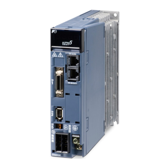
CHAPTER 2 WIRING Servo amplifier (frame3) Analog monitor (CN4) Keypad The analog waveform is monitored. 4-digit 7-segment LED, 4 buttons and monitor terminals are installed. Charge LED RS-485 (CN3A (IN), CN3B (OUT)) Upper side: CN3A, lower side: CN3B Power supply (TB1) — Main power Sequence I/O (CN1) -
Page 53: Configuration
CHAPTER 2 WIRING 2.1.2 Configuration The figure on page 2-7 shows the general configuration of devices. There is no need to connect all devices. The size on each device in the figure is not drawn at the uniform scale (same as other chapters). …
-
Page 54
CHAPTER 2 WIRING Connecting to peripheral devices (Servo amplifier frame 1) For lead wire type motors, connect cables as shown below. MCCB/ELCB AC reactor Surge absorber Servo operator (optional) Used for copying parameters and editing operations. Power filter Electromagnetic contactor Servo amplifier RS-485 communications… -
Page 55
CHAPTER 2 WIRING Sample Connection Diagram (Servo amplifier frame 1) External braking External regenerative resistor resistor PN junction No built-in braking resistor No built-in regenerative resistor Connect the external braking resistor Connect the external regenerative across RB1 and RB2. resistor across RB1 and RB2. N(-) P(+) In case of the single-phase 200 V input… -
Page 56
CHAPTER 2 WIRING Connecting to peripheral devices (Servo amplifier frames 2, 3 and 4) For the motors with the Cannon connector, connect cables as shown below. MCCB/ELCB Servo Operator (optional) AC reactor Using this, parameter Surge copying and editing can be absorber performed. -
Page 57
CHAPTER 2 WIRING Sample Connection Diagram (Servo amplifier frames 2, 3 and 4) External regenerative External braking resistor resistor Jumper wire PN junction regenerative Built-in resistor provided. Built-in braking resistor provided. Connect the external regenerative resistor Connect the external braking resistor across RB1 and RB2 across RB1 and RB2 Open Collector Connection… -
Page 58: Sequence I/O
CHAPTER 2 WIRING 2.1.3 Sequence I/O CN1 of RYHF5-VV2 type. The wiring connectors are not included with the servo amplifier. Connector kit type: WSK-D26P *FFB *FFZ *FFA VREF CONT5 TREF CONT4 OUT3 CONT3 OUT2 CONT2 OUT1 CONT1 COMOUT COMIN Terminal Function symbol Pull-up voltage input at open collector input…
-
Page 59
CHAPTER 2 WIRING Terminal Function symbol CONT1 Sequence input (sink/source supported) CONT2 Supply command signals to the servo amplifier through these terminals. CONT3 12 to 24 VDC/8 mA (per point). Photocoupler isolation. The COMIN is the reference potential terminal. CONT4 (Soft filter 0.5 ms, agreement of two scans, except for interrupt input) CONT5 The delay of hardware filter detection is 0.1 ms with interrupted input. -
Page 60: Pulse Input (Ppi, Ca, *Ca, Cb, *Ca)
CHAPTER 2 WIRING 2.1.3.1 Pulse Input (PPI, CA, *CA, CB, *CA) Pulse input terminal Format: Command pulse/direction, forward/reverse pulse, A/B phase pulse (parameter switch) Max. input frequency: 1 MHz (differential input), 200 kHz (open collector input) (A/B phase pulse: 250 kHz (differential input), 50 kHz (open collector input) (1) Differential input The PPI terminal is not used.
-
Page 61: Pulse Output (Ffa, *Ffa, Ffb, *Ffb, Ffz, *Ffz)
CHAPTER 2 WIRING 2.1.3.2 Pulse Output (FFA, *FFA, FFB, *FFB, FFZ, *FFZ) The pulses proportional to the motor revolutions are output as A/B phase pulse. The number of output pulses per motor revolution can be specified in the parameter (PA1_08). …
-
Page 62: Sequence Input (Cont1, Cont2, Cont3
CHAPTER 2 WIRING 2.1.3.5 Sequence Input (CONT1, CONT2, CONT3, … COMIN) This is the input terminal for sequence control. The terminal allows sink input/source input. Use the terminal within the range from 12 VDC to 24 VDC. A current of approx.
-
Page 63: Analog Monitor Output (Cn4: Mon1, Mon2, And M5)
CHAPTER 2 WIRING 2.1.5 Analog Monitor Output (CN4: MON1, MON2, and M5) This is the analog voltage output terminal from the servo amplifier, Set the details to be output using the parameter. Max. ±10 V/0.5 mA Resolution: 14 bits/±full scale MON1 MON2 Servo amplifier…
-
Page 64: P-N Junction
CHAPTER 2 WIRING 2.2 P-N Junction Directly connect the DC link circuit of two servo amplifiers to exchange power. In a system having a powering (driving) shaft and regenerating (back tension) shaft such as the winder/unwinder unit, the power consumption of the entire system can be reduced. Do not supply main power to the servo amplifier on the other side of the P-N junction.
-
Page 65: Servomotor
CHAPTER 2 WIRING 2.3 Servomotor There are wiring of the following three units: the main body of the servomotor, brake (servomotor equipped with a brake) and encoder. CAUTION Keep consistency in the phase order between the servomotor and servo amplifier. …
-
Page 66: Encoder
CHAPTER 2 WIRING 2.4 Encoder 2.4.1 Encoder Cable Use shielded cables for wiring of the servomotor encoder. The optional cable for the servomotor is a cable having bend resistance, which is also UL standard compliant. Use a regular twisted pair batch shield cable if the servomotor and cable do not work. …
-
Page 67: Encoder Cable
CHAPTER 2 WIRING 2.4.2 Encoder Cable To fabricate the encoder cable by yourself, take care of the following. Do not install a relaying terminal block between the servo amplifier and motor. Use a shielded cable. Connect the shielded cable with the designated connector pin, connector shell or cable clamp on both sides.
-
Page 68
CHAPTER 2 WIRING Wiring length within 10 m Servo amplifier Servomotor P5 1 7(H)[B] P5 M5 2 8(G)[I] M5 BAT+ 3 1(T) BAT+ BAT- 4 2(S) BAT- SIG+ 5 5(C)[D] SIG+ SIG- 6 4(D)[H] SIG- Shell 3 [F] FG Connector no. on motor side Lead wire Connector no. -
Page 69: Description Of I/O Signals
CHAPTER 2 WIRING 2.5 Description of I/O Signals List of input signals The signal assigned to the sequence input terminal can be specified with a parameter. Default Name Setting range Change value PA03_01 CONT1 signal assignment PA03_02 CONT2 signal assignment 1 to 78 Power PA03_03 CONT3 signal assignment…
-
Page 70: List Of Output Signals
CHAPTER 2 WIRING List of output signals Specify the signals assigned to sequence output terminals, using parameters. Name Setting range Default value Change PA03_51 OUT1 signal assignment Power 1 to 95 PA03_52 OUT2 signal assignment PA03_53 OUT3 signal assignment Sequence output signal Function Function Ready for servo-on [RDY]…
-
Page 71: Input Signal
CHAPTER 2 WIRING Input signal Servo-on [S-ON]: Sequence input signal (Reference value 1) The signal makes the servomotor ready to rotate. Function The servomotor is ready to rotate while the servo-on [S-ON] signal remains turned on. When the servo-on signal is turned off, the gate for IGBT is turned off and the servomotor does not rotate.
-
Page 72
CHAPTER 2 WIRING Rotation speed Speed command (VREF terminal) voltage PA1_41: Manual feed speed 1 PA1_42: Manual feed speed 2 PA1_43: Manual feed speed 3 PA1_44: Manual feed speed 4 PA1_45: Manual feed speed 5 PA1_46: Manual feed speed 6 PA1_47: Manual feed speed 7 (2) Position control In the position control mode, only pulse inputs are accepted. -
Page 73: Start Positioning [Start]: Sequence Input Signal (Reference Value 4)
CHAPTER 2 WIRING Start positioning [START]: Sequence input signal (Reference value 4) Positioning motion is executed according to positioning data or immediate value data sent via RS-485 communications. This function is enabled only if parameter PA1_01 is “7” (positioning operation). …
-
Page 74: Homing [Org]: Sequence Input Signal (Reference Value 5)
CHAPTER 2 WIRING Homing [ORG]: Sequence input signal (Reference value 5) Homing position LS [LS]: Sequence input signal (Reference value 6) A homing motion is executed and the home position is determined. These functions are enabled only if the extension mode (parameter PA1 _ 01= 6) and the positioning operation (parameter PA1_01=7) are selected.
-
Page 75
CHAPTER 2 WIRING To perform homing, use up positive over-travel [+OT] and negative over-travel [-OT] signals to assure safety. Homing direction Detection of over-travel signal If homing is started from position A in the figure above, the home position LS is detected and stoppage is caused. -
Page 76: Over-Travel In Positive Direction [+Ot]: Sequence Input Signal (Reference Value 7)
CHAPTER 2 WIRING Home position LS signal edge selection (PA2_13) After the trailing edge of the LS is detected, the Z-phase signal after the home position LS is detected. Deceleration operation for creep speed (PA2_15) Controlled stop is caused during homing upon detection of the home position LS (or reference signal for shift operation), followed by reverse rotation until the point before the home position LS is reached, and then homing is performed again at the creep speed.
-
Page 77
CHAPTER 2 WIRING Parameter setting To assign the +OT signal to a sequence input terminal, specify the corresponding value («7») to the input terminal function setting parameter. For the -OT signal, specify («8»). Relevant description (1) Direction of detection The +OT signal is detected during a travel of the servomotor in the positive direction. -
Page 78: Forced Stop [Emg]: Sequence Input Signal (Reference Value 10)
CHAPTER 2 WIRING Forced stop [EMG]: Sequence input signal (Reference value 10) This signal is used to forcibly stop the servomotor. Function The servomotor is forcibly stopped while the forced stop [EMG] signal remains turned on (switch:open). This signal is enabled in all control modes and it is given the highest priority. Because the safety and detection speed are significant, the forced stop signal is generally connected to the servo amplifier directly.
-
Page 79: Alarm Reset [Rst]: Sequence Input Signal (Reference Value 11)
CHAPTER 2 WIRING Alarm reset [RST]: Sequence input signal (Reference value 11) The alarm reset signal resets alarm detection of the servo amplifier. Function The sequence input signal resets alarm detection of the servo amplifier. The rising edge of the alarm reset [RST] signal resets alarm detection. By starting the test operation mode at the keypad, operating the PC Loader or turning the power on again, the alarm can be reset.
-
Page 80: Acc0: Sequence Input Signal (Reference Value 14)
CHAPTER 2 WIRING ACC0: Sequence input signal (Reference value 14) ACC0 switches the acceleration/deceleration time. Function (1) Acceleration/deceleration time switch The acceleration time and deceleration time of the servomotor follow the setting of PA1_37 to 40 (acceleration time, deceleration time). The acceleration time and deceleration time can be set separately.
-
Page 81: Position Preset: Sequence Input Signal (Reference Value 16)
CHAPTER 2 WIRING Position preset: Sequence input signal (Reference value 16) The command position and feedback position are preset (overwritten). Function The command position and the feedback position are made the reference value of PA2_19 (preset position) at the rising edge. However, the deviation is subtracted from the feedback position.
-
Page 82: Gain Swtich: Sequence Input Signal (Reference Value 17)
CHAPTER 2 WIRING Gain swtich: Sequence input signal (Reference value 17) To switch the gain (response capability) of the servo system. Function When PA1_61 (gain changing factor) is set at «3» (external switch: CONT signal), the CONT signal assigned to this function switches the gain of the servo system. The control gain parameters that are enabled with the gain switch are listed in the table below.
-
Page 83
CHAPTER 2 WIRING Torque limit under speed control and position control The following settings can be specified as a limitation set on the torque. [1] TREF terminal voltage (10 V/300%) [2] Forward rotation torque limit (PA1_27), reverse rotation torque limit (PA1_28) [3] Second torque limit (PA2_58) [4] Third torque limit (PA2_60) If «0»… -
Page 84: Immediate Value Continuation: Sequence Input Signal (Reference Value 22)
CHAPTER 2 WIRING Parameter setting If the torque limit signal is assigned to a sequence input terminal, specify the corresponding value («19» or «20») to the input terminal function setting parameter. If the torque limit signal is not assigned to the sequence input terminal, the settings of PA1_27 (forward rotation torque limit) and PA1_28 (reverse rotation torque limit) are always enabled.
-
Page 85
CHAPTER 2 WIRING Parameter setting To assign the immediate value continuation command to a sequence input terminal, enter the corresponding value (“22”) in the input terminal function setting parameter. Relevant signal reference values include following. Allocated signal Immediate value continuation: sequence input signal Immediate value continuation completion: sequence output signal… -
Page 86: Immediate Value Change: Sequence Input Signal (Reference Value 23)
CHAPTER 2 WIRING Immediate value change: Sequence input signal (Reference value 23) The target position and target speed of immediate value start can be changed at an arbitrary timing. This function is enabled only if “7” (positioning operation) is selected for parameter PA1_01. …
-
Page 87: Electronic Gear Numerator Selection 0: Sequence Input Signal (Reference Value 24)
CHAPTER 2 WIRING (2) Command position / command speed / ABS/INC Each piece of data can be changed arbitrarily. The data at the timing of rising edge of the immediate value continuation command is enabled. However, the ABS/INC signal retains the state enabled at the rising edge of the start positioning signal.
-
Page 88: Command Pulse Ratio 1: Sequence Input Signal (Reference Value 27)
CHAPTER 2 WIRING Parameter setting To assign pulse command inhibit to a sequence input terminal, specify the corresponding value («26») to the input terminal function setting parameter. Command pulse ratio 1: Sequence input signal (Reference value 27) Command pulse ratio 2: Sequence input signal (Reference value 28) Use the parameters to change the multiplication of the command input pulse under position control in the extension mode.
-
Page 89: Proportional Control: Sequence Input Signal (Reference Value 29)
CHAPTER 2 WIRING Proportional control: Sequence input signal (Reference value 29) Proportional band control is adopted as a servo amplifier control method. Function With S-ON signal turned on, the signal will be turned on while the servomotor shaft is mechanically locked.
-
Page 90: Positioning Cancel: Sequence Input Signal (Reference Value 32)
CHAPTER 2 WIRING (2) ABS/INC (positioning data) After the pause (“31”) signal is turned off, the remaining motion continues without relations to the absolute (ABS) or incremental (INC) mode of positioning data. This signal is irrelevant to the setting of the INC/ABS system selection parameter (PA1_02). (3) Brake timing The brake is not applied in a pause.
-
Page 91: Teaching: Sequence Input Signal (Reference Value 35)
CHAPTER 2 WIRING Teaching: Sequence input signal (Reference value 35) The current position of the servomotor is written to the position data in the positioning data. This function is enabled only if “7” (positioning operation) is selected for parameter PA1_01. …
-
Page 92: Position Control: Sequence Input Signal (Reference Value 37)
CHAPTER 2 WIRING Control mode The enabled control mode includes the following. Control mode selection PA1_1: Control mode selection Position control Speed control Position control Torque control Speed control Torque control For details, refer to «CHAPTER 4 PARAMETER.» Parameter setting To assign control mode selection to a sequence input terminal, specify the corresponding value («36») to the input terminal function setting parameter.
-
Page 93
CHAPTER 2 WIRING Parameter setting To assign position control to a sequence input terminal, specify the corresponding value («37») to the input terminal function setting parameter. For command pulse ratio 1, specify («27»), while specify («28») for command pulse ratio 2. [Example] To conduct operation with a command pulse input Operation with a command pulse input is enabled while command pulse ratio 1 or… -
Page 94
CHAPTER 2 WIRING The conditions for enabling position control with the command pulse input are shown below. Servo-on [S-ON] = ON Forced stop [EMG] = ON (Control output ready for servo-on [RDY] = ON) Position control (37) = ON The command pulse is enabled while command pulse ratio 1 (27) or command pulse ratio 2 (28) remains turned on. -
Page 95: Torque Control: Sequence Input Signal (Reference Value 38)
CHAPTER 2 WIRING Torque control: Sequence input signal (Reference value 38) Use to conduct torque control in the extension mode. This function is enabled only if «6» (extension mode) is selected for parameter PA1 _ 01. Function Turn on to conduct torque control in the extension mode (mode compatible with that of conventional α…
-
Page 96: Override Enable: Sequence Input Signal (Reference Value 43)
CHAPTER 2 WIRING (4) Output torque The output torque of the servomotor has individual differences (variation) of about 0 to +5% under torque control. Continuous operation can be made if the output torque is within the rated torque. (5) Torque limit For details, refer to «Torque limit 0,1.»…
-
Page 97
CHAPTER 2 WIRING Relevant description Override ratio Traveling Override Override Override Override speed (1) Override multiplication The multiplication applicable while the override enable signal remains turned on is shown in the table on the right. If override enable is turned off, the original speed (100% traveling speed) becomes effective. -
Page 98: Interrupt Input Enable: Sequence Input Signal (Reference Value 48)
CHAPTER 2 WIRING Interrupt input enable: Sequence input signal (Reference value 48) Interrupt input: Sequence input signal (Reference value 49) Use to realize the interrupt positioning function. These functions are enabled only if «6» (extension mode) or «7» (positioning operation) is selected for parameter PA1_01.
-
Page 99
CHAPTER 2 WIRING (Example: Automatic operation) PA2_20 Speed (interrupt traveling unit amount) Time Start positioning AD 3~ AD0 Interrupt input enable Disabled Interrupt input In-position (level) Interrupt position detection (2) Positioning accuracy The traveling amount for interrupt positioning is the value corresponding to the feedback position. The interrupt input signal is subject to the delay in detection of the hardware filter (0.05 ms) The positioning accuracy at a mechanical system traveling speed of 1000 mm/s (60 m/min) is: 1000 x 0.00005 = 0.05 mm. -
Page 100: Deviation Clear: Sequence Input Signal (Reference Value 50)
CHAPTER 2 WIRING Deviation clear: Sequence input signal (Reference value 50) The difference (deviation) between the command position and feedback position is zeroed. Function The difference (deviation) between the command position and the feedback position is zeroed while the deviation clear signal remains turned on. The command position changes to the feedback position.
-
Page 101: Free-Run [Bx]: Sequence Input Signal (Reference Value 54)
CHAPTER 2 WIRING PA1_44 Manual feed speed 4 PA1_45 Manual feed speed 5 PA1_46 Manual feed speed 6 PA1_47 Manual feed speed 7 (2) Under torque control The rotation speed of the servomotor is limited with the speed selected with multi-step speed [X1], [X2] and [X3].
-
Page 102: Edit Permission: Sequence Input Signal (Reference Value 55)
CHAPTER 2 WIRING Edit permission: Sequence input signal (Reference value 55) Editing operation for parameters and so on is limited with an external sequence input signal. Function The edit permission assigned to a CONT input signal controls editing operation and test operation made at the keypad or PC Loader.
-
Page 103
CHAPTER 2 WIRING Parameter setting To assign the edit permission to a sequence input terminal, specify the corresponding value («55») to the input terminal function setting parameter. Relevant description (1) Parameter write protection Specify «1» (write protection) to PA2_74 (parameter write protection) to disable key operation at the keypad and parameter editing at the PC Loader. -
Page 104: Anti Resonance Frequency Selection 0: Sequence Input Signal (Reference Value 57)
CHAPTER 2 WIRING Anti resonance frequency selection 0: Sequence input signal (Reference value 57) Anti resonance frequency selection 1: Sequence input signal (Reference value 58) Select the anti resonance frequency, which is a vibration suppressing control function. Function In a spring characteristic structure such as the robot arm and transfer machine, vibration is caused at the end of the workpiece upon sudden acceleration or deceleration of the motor.
-
Page 105: Ad0: Sequence Input Signal (Reference Value 60)
CHAPTER 2 WIRING AD0: Sequence input signal (Reference value 60) AD1: Sequence input signal (Reference value 61) AD2: Sequence input signal (Reference value 62) AD3: Sequence input signal (Reference value 63) Enter the address of positioning data to be followed, among AD0 to AD3. Refer to the table below when entering.
-
Page 106: Positioning Data Selection: Sequence Input Signal (Reference Value 77)
CHAPTER 2 WIRING Positioning data selection: Sequence input signal (Reference value 77) Positioning data operation and immediate value operation are switched over. Function The positioning data can be switched at an arbitrary timing between the following: positioning within 15 points with internal positioning data and positioning with immediate value data for frequent positioning data change.
-
Page 107
CHAPTER 2 WIRING <Logic of broadcast cancel signals> Broadcast cancel Broadcast Uni-cast No allocation Enabled Enabled Enabled Disabled Cancels the queries of broadcast, without responding. Relevant descriptions <Signal switching timing> 1) When switching the broadcast cancellation status between ON and OFF using the CONT signals (CONT9 to 24) via communications, see «2. -
Page 108: Ready For Servo-On [Rdy]: Sequence Output Signal (Reference Value 1)
CHAPTER 2 WIRING Output signal Ready for servo-on [RDY]: Sequence output signal (Reference value 1) This signal is turned on if the servomotor is ready to operate. Function The ready for servo-on signal is turned on if the conditions shown in the table below are satisfied. Signal Function Signal name…
-
Page 109: In-Position [Inp]: Sequence Output Signal (Reference Value 2)
CHAPTER 2 WIRING In-position [INP]: Sequence output signal (Reference value 2) This signal is turned on after a positioning motion is finished. Function (1) Status of in-position signal The state under position control is shown in the table below. Factor Sequence status Status of in-position signal…
-
Page 110
CHAPTER 2 WIRING Rotation speed PA1_32: Zero deviation range/In-position range Time Zero speed Zero deviation In-position (level) PA1_35: In-position judgment time In-position (single shot) ON PA1_34: In-position minimum OFF time / Single shot ON time (3) Interrupt positioning Level: The signal is turned on if conditions (A) and (B) below are satisfied. (A) The rpm of the servomotor is within the setting of PA1_30 (zero speed range). -
Page 111: Speed Limit Detection: Sequence Output Signal (Reference Value 11)
CHAPTER 2 WIRING Speed limit detection: Sequence output signal (Reference value 11) The signal is turned on if the rotation speed of the servomotor reaches the preset speed limit. Function The signal is output to an external device if the rpm of the servomotor reaches the preset speed limit.
-
Page 112
CHAPTER 2 WIRING Parameter setting To assign the brake timing output to a sequence output terminal, specify the corresponding value («14») to the output terminal function setting parameter. The brake attached to the brake-attached servomotor is «for retention.» Do not use it for regenerative. -
Page 113
CHAPTER 2 WIRING (3) Upon main power supply OFF Main power suppy Base signal Ready for servo-on [RDY] Brake timing output 2-65 Description of I/O Signals… -
Page 114: Alarm Detection (Normally Open Contact): Sequence Output Signal (Reference Value 16)
CHAPTER 2 WIRING Alarm detection (normally open contact): Sequence output signal (Reference value 16) Alarm detection (normally closed contact): Sequence output signal (Reference value 76) Normally open contact: Signal is turned on (switch: closed) if servo amplifier detects an alarm. Normally closed contact: Signal is turned on (switch: open) if servo amplifier detects an alarm.
-
Page 115: Point Detection, Area 1: Sequence Output Signal (Reference Value 17)
CHAPTER 2 WIRING Point detection, area 1: Sequence output signal (Reference value 17) Point detection, area 2: Sequence output signal (Reference value 18) The current position of the servomotor is detected and output in these signals. This function is enabled after homing or position preset. …
-
Page 116: Limiter Detection: Sequence Output Signal (Reference Value 19)
CHAPTER 2 WIRING Limiter detection: Sequence output signal (Reference value 19) With this signal, the limiter function availability can be checked. This function becomes enabled after homing or position preset. Function The limiter function is enabled in the position control mode, and not enabled in the interrupt positioning operation.
-
Page 117: Ot Detection: Sequence Output Signal (Reference Value 20)
CHAPTER 2 WIRING OT detection: Sequence output signal (Reference value 20) This signal is output if the over-travel (OT) signal is turned off. Function The OT detection («20») sequence output is issued while the +OT (7) or -OT (8) sequence input signal terminal remains turned off.
-
Page 118: Cycle End Detection: Sequence Output Signal (Reference Value 21)
CHAPTER 2 WIRING Cycle end detection: Sequence output signal (Reference value 21) This signal is turned on after the cycle end position is reached if the cycle end is assigned to the positioning data. PA2_41 (sequential start selection) must be set at “1” (enable). Change PA2_40 (internal positioning data selection) to “1”…
-
Page 119: Homing Completion: Sequence Output Signal (Reference Value 22)
CHAPTER 2 WIRING Neither positioning cancel nor pause gives effects on cycle end detection. When positioning data number 15 is reached during sequential operation, the cycle end process is executed. If data continuation designation is included in positioning data, operation starts at the next data having no data continuation designation.
-
Page 120: Zero Speed [Nzero]: Sequence Output Signal (Reference Value 24)
CHAPTER 2 WIRING Parameter setting To assign zero deviation to a sequence output terminal, specify the corresponding value («23») to the output terminal function setting parameter. Zero speed [NZERO]: Sequence output signal (Reference value 24) The signal is turned on if the servomotor rotation speed is nearly zero. …
-
Page 121: Torque Limit Detection: Sequence Output Signal (Reference Value 26)
CHAPTER 2 WIRING Relevant description PA1_25 (max. rotation speed (for position and speed)) Specify the upper limit of the servomotor rotation speed which is specified with a parameter. If the maximum rotation speed is exceeded due to an override or similar, the servomotor rotates at the specified value.
-
Page 122
CHAPTER 2 WIRING Standard series Overload warning time (at 3000 r/min) Overload warning value=100% Overload warning value=80% Overload warning value=60% Overload warning value=40% Overload warning value=20% Load factor [%] Overload warning time (at 6000 r/min) Overload warning value=100% Overload warning value=80% Overload warning value=60% Overload warning value=40% Overload warning value=20%… -
Page 123: Servo Control Ready [S-Rdy]: Sequence Output Signal (Reference Value 28)
CHAPTER 2 WIRING Servo control ready [S-RDY]: Sequence output signal (Reference value 28) Use the signal to check that the servo amplifier and servomotor operate correctly. Function The servo control ready signal remains turned on while the conditions listed in the table below are satisfied.
-
Page 124: Data Error: Sequence Output Signal (Reference Value 30)
CHAPTER 2 WIRING Relevant description For details, refer to «Edit permission.» Data error: Sequence output signal (Reference value 30) The signal is turned on if the data reading or writing process does not proceed correctly. Function The signal is turned on if the address and data are incorrect (drifting beyond the specification limit) when performing teaching.
-
Page 125
CHAPTER 2 WIRING List of alarm detail and code Alarm detail ALM4 ALM3 ALM2 ALM1 ALM0 Code Indication Order No alarm (normal operation) nonE Overload 1 Overload 2 — (Unused) Amplifier Overheat Internal Breaking Resistor Overheat External Breaking Resistor Overheat Breaking Transistor Error Inrush Current Suppression… -
Page 126: Ot Detection: Sequence Output Signal (Reference Value 38)
CHAPTER 2 WIRING Type Nature of alarm ALM4 ALM3 ALM2 ALM1 ALM0 Code Battery warning Maintenance function Life warning BCD error Address error Out-of-range error Command rejection BCD error Data error Out-of-range error, 0 data write Negative sign designation If two or more alarms occur simultaneously, alarms are output in the priority specified in the table above.
-
Page 127: Home Position Ls Detection: Sequence Output Signal (Reference Value 40)
CHAPTER 2 WIRING Home position LS detection: Sequence output signal (Reference value 40) The signal is output while the home position LS signal (input signal) remains turned on. Function The sequence output corresponding to home position LS detection is turned on while the home position LS sequence input signal remains turned on.
-
Page 128: Life Warning: Sequence Output Signal (Reference Value 46)
CHAPTER 2 WIRING Life warning: Sequence output signal (Reference value 46) The life of internal main circuit capacitors of the servo amplifier and that of the cooling fan are calculated and output its signal. Function The life of internal main circuit capacitors of the servo amplifier and that of the cooling fan are calculated and, if either exceeds the rated time, a life warning is turned on.
-
Page 129
CHAPTER 2 WIRING Relevant description (1) M code setting range Enter the M code in a binary between 00h and FFh. (2) Output at start (output in start) / output at completion (output after completion) You can select the M code output timing between during execution of positioning data (output at start) and after execution of positioning data (output at completion). -
Page 130: Position Preset Completion: Sequence Output Signal (Reference Value 75)
CHAPTER 2 WIRING Output at completion (after-process output) The signal is output at positioning completion and is hold. Output after M code issuing Rotation M code 20 speed Time Timer (positioning data) Ready for servo-on Start positioning AD3 to AD0 In-position (level) M code…
-
Page 131: Immediate Value Continuation Completion: Sequence Output Signal (Reference Value 80)
CHAPTER 2 WIRING Parameter setting Enter the corresponding value (“79”) to the output terminal function setting parameter. Relevant signal reference values are shown below. Signal Immediate value continuation: sequence input signal Immediate value continuation permission: sequence output signal Immediate value continuation completion: sequence output signal Immediate value continuation completion: Sequence output signal (Reference value 80) The signal is turned on after continuation of immediate value operation is processed according to an…
-
Page 132: Command Positioning Completion: Sequence Output Signal (Reference Value 82)
CHAPTER 2 WIRING Parameter setting Enter the corresponding value (“81”) to the output terminal function setting parameter. The relevant signal reference values are shown below. Allocated signal Immediate value change Immediate value change completion Command positioning completion: Sequence output signal (Reference value 82) The signal is turned on after the command value inside the servo amplifier is completed.
-
Page 133: Range 1 Of Position: Sequence Output Signal (Reference Value 83)
CHAPTER 2 WIRING If the command positioning completion signal is allocated to an output signal, the condition for the next start signal is activation of the command positioning completion signal. Refer to the timing chart below. (Example: Automatic operation continuation) Speed Motor speed…
-
Page 134
CHAPTER 2 WIRING 1) Setting value of PA3_92 < Setting value of PA3_93 Range1 of position: Setting2 (PA3_93) Range1 of position: Setting1 (PA3_92) 1000.00 3000.00 Motor current position Range1 of position 2) Setting value of PA3_92 > Setting value of PA3_93 Range1 of position: Setting2 (PA3_93) Range1 of position: Setting1 (PA3_92) 1000.00… -
Page 135
CHAPTER 2 WIRING Interrupt positioning detection: Sequence output signal (Reference value 85) This signal outputs the interrupt positioning motion mode status. Function The signal turns on during interrupt positioning motion, and turns off with any of the following conditions. (1) When the interrupt input enabling signal is turned off after the positioning motion completion. -
Page 136
CHAPTER 2 WIRING Parameter setting Enter the corresponding value (“85”) to the output terminal function setting parameter. Relevant description If the temporary stop is turned on during interrupt positioning motion, the mode is regarded as the interrupt positioning mode. (The interrupt positioning detection signal remains on.) 2-88 Description of I/O Signals… -
Page 137: Cont Through: Sequence Output Signal (Setting Value 91 To 95)
CHAPTER 2 WIRING CONT Through: Sequence Output Signal (Setting value 91 to 95) This function allows communications input signals to be output via OUT signals of the hardware. Function The signals set to CONT 20 to 24 can be output through OUT signals 1 to 3 of the hardware. When a CONT□…
-
Page 138: Connection Example To Host Controller
CHAPTER 2 WIRING 2.6 Connection Example to Host Controller For products not described in this manual, be sure to refer to the manual attached to the corresponding product. Refer to the connection diagram described here. The servomotor specified in the connection diagram is equipped with a brake. If the servomotor is equipped with no brake, the Br terminal is not provided.
-
Page 139: Connection Example (Positioning Terminal: Np1Sf-Hp4Dt)
CHAPTER 2 WIRING 2.6.1 Connection Example (Positioning terminal: NP1SF-HP4DT) A connection example with MICREX-SX Series four-axis pulse output positioning terminal is shown below. The maximum output frequency is 250 kHz. This terminal needs no FB. For details, refer to the manual prepared for the positioning terminal. 2-91 Connection Example to Host Controller…
-
Page 140: Connection Example (Positioning Module: Np1F-Mp2)
CHAPTER 2 WIRING 2.6.2 Connection Example (Positioning module: NP1F-MP2) A connection example with MICREX-SX Series pulse two-axis positioning module is shown below. The maximum output frequency is 200 kHz. For details, refer to the manual prepared for the positioning module. 2-92 Connection Example to Host Controller…
-
Page 141: Connection Example (Positioning Module: F3Yp14-0N/ F3Yp18-0N)
CHAPTER 2 WIRING 2.6.3 Connection Example (Positioning module: F3YP14-0N/ F3YP18-0N) A connection example with the F3YP14-0N type positioning module made by Yokogawa Electric is shown below. For the PLC, refer to the corresponding manual. 2-93 Connection Example to Host Controller…
-
Page 142: Connection Example (Positioning Unit: Qd75 Type)
CHAPTER 2 WIRING 2.6.4 Connection Example (Positioning unit: QD75 type) A connection example with the QD75 type positioning unit made by Mitsubishi Electric is shown below. Connection between the QD75 type positioning unit and servo amplifier is shown. For the PLC, refer to the corresponding manual. 2-94 Connection Example to Host Controller…
-
Page 143: Chapter 3 Operation
CHAPTER 3 OPERATION 3.1 Signal Description (Priority among Input Signals) ·································· 3-2 3.2 Selection of Operation Procedure ························································ 3-3 3.3 Operation Check ··············································································· 3-4 3.3.1 Power On ··················································································· 3-4 3.3.2 Power-On/Servo Control-Ready [S-RDY] ··········································· 3-5 3.3.3 Servo-On [S-ON]/Ready for Servo-On [RDY] ······································ 3-5 3.3.4 If the Servomotor Fails to Start ························································…
-
Page 144: Signal Description (Priority Among Input Signals)
CHAPTER 3 OPERATION 3.1 Signal Description (Priority among Input Signals) Input signals of the servo amplifier for stopping the motor shaft are received first in view of safety. Applicable signal Description (Function No.) Free-run command (54) 01 Operation signal always given highest priority …
-
Page 145: Selection Of Operation Procedure
CHAPTER 3 OPERATION 3.2 Selection of Operation Procedure The VV type servo amplifier is capable of speed control and torque control with analog voltages, position control with pulse, positioning data operation with Di/Do signals or RS-485 communications, and immediate value data operation with RS-485 communications. Follow the flow chart below to select the desired operation and enter parameters, etc.
-
Page 146: Operation Check
CHAPTER 3 OPERATION 3.3 Operation Check 3.3.1 Power On Connect the commercial power supply and the servomotor to the servo amplifier. For the wiring method, refer to «CHAPTER 2 WIRING.» Supplying commercial power Operate MCCB/ELCB to supply power. If necessary, insert an electromagnetic contactor in the upstream of the main power input so that the power can be shut off at any time.
-
Page 147: Power-On/Servo Control-Ready [S-Rdy]
CHAPTER 3 OPERATION If the error code on the display blinks If the keypad display blinks, an alarm is detected. 3.3.2 Power-On/Servo Control-Ready [S-RDY] The servo control ready [S-RDY] signal is issued about 2.0 seconds after the main power is supplied. The CPU inside the servo amplifier diagnoses itself and, if the result is correct, the signal is issued and remains turned on until the power is shut down.
-
Page 148: If The Servomotor Fails To Start
CHAPTER 3 OPERATION 3.3.4 If the Servomotor Fails to Start If the servomotor fails to start or unexpected indication is given, it is recommended to undergo the procedure described in “14.6.8 Diagnosis to be Made If the Servomotor Fails to Start” on page 14-34, using PC Loader.
-
Page 149: Operation
CHAPTER 3 OPERATION 3.4 Operation 3.4.1 Test Operation at Keypad Using the test operation mode of the keypad, check the motor rotation. In case of a servomotor equipped with a brake, supply 24 VDC to release the brake. The motor rotates even without a sequence I/O signal. The relevant parameter settings and default values are shown below.
-
Page 150: Position Control (Pulse)
CHAPTER 3 OPERATION 3.4.2 Position Control (Pulse) The shaft rotation position is controlled under position control according to the pulse input of the servo amplifier. The pulse operation procedure is shown below. (2) Position control setting (3) Position control check (4) Pulse amount check (1) Pulse setting (1) Pulse setting…
-
Page 151: Position Control (Pulse)
CHAPTER 3 OPERATION (2) Position control setting The factory shipment settings of the VV type servo amplifier are as follows. Assignment of input terminal (CONT input signal) CONT1: Servo-on [S-ON] (Function No. 1) CONT2: Alarm reset [RST] (Function No. 11) CONT3 to CONT24: (No designation) …
-
Page 152: Speed Control
CHAPTER 3 OPERATION 3.4.3 Speed Control The shaft rotation speed is controlled in the speed control mode according to the speed command voltage input [VREF] of the servo amplifier or parameter setting. If parameter PA1_01 is set at «1,» the speed control mode starts after the RDY signal is turned on. While the manual forward command [FWD] or manual reverse command [REV] signal is turned on, the motor accelerates and turns at a constant speed, and deceleration starts when the signal is turned off.
-
Page 153: Torque Control
CHAPTER 3 OPERATION 3.4.4 Torque Control The shaft output torque is controlled under the torque control according to torque command voltage input [TREF] of the servo amplifier or a parameter setting. If parameter PA1_01 is set at «2,» the torque control mode starts after the RDY signal is turned on. The torque is output while the manual forward command [FWD] or manual reverse command [REV] signal is turned on, while the torque is reduced to zero after the signal is turned off.
-
Page 154: Mode Selection
CHAPTER 3 OPERATION 3.4.5 Mode Selection The operation control mode can be changed with parameter settings shown below and control mode switching signal. Control mode (function No.36) PA1_01:Control mode selection Control mode selection=OFF Control mode selection=ON Position control Speed control Position control Torque control Speed control…
-
Page 155: Extension Mode
CHAPTER 3 OPERATION 3.4.6 Extension Mode Compatible mode with standard type of FALDIC- Series If parameter PA1_01 is “6,” operation is made with control signal inputs similar to those of the Series. If the pulse operation is performed, pulses are active while «position control» and «pulse ratio 1 (2)» are turned on.
-
Page 156
CHAPTER 3 OPERATION Speed Zero deviation Zero speed In-position (level) In-position (single shot) PA1_34 The single-shot output is forcibly turned off if the zero deviation signal is turned off. Deviation clear The difference between the command position (pulse input) and feedback position (present motor position) is the deviation. -
Page 157: Homing
CHAPTER 3 OPERATION 3.4.7 Homing When in-position [INP] is turned on, activation of the homing command [ORG] starts a homing motion. Enter parameters PA2_06 through 18 and 24 to configure the homing pattern. Homing speed Speed Homing creeping speed Shift amount for homing Time [RDY]…
-
Page 158: Interrupt Positioning
CHAPTER 3 OPERATION 3.4.8 Interrupt Positioning Turn interrupt input enable signal on during operation with a forward [FWD] or reverse [REV] command to start to move by an interrupt traveling unit amount, which is specified at parameter PA2_20, at the activating edge (OFF-to-ON transition) of the interrupt input.
-
Page 159
CHAPTER 3 OPERATION (1) After the interrupt input enable signal is turned on, the activating edge (OFF-to-ON transition) of the first interrupt input is enabled. (2) Allocate the interrupt input to the CN1 terminal of CONT1 to 5. Generally, the sequence input and output signals are recognized in about 1 to 2 ms by the software, however, the interrupt input detects the signals by the hardware. -
Page 160: Torque Limit
CHAPTER 3 OPERATION 3.4.9 Torque Limit Torque limit is always enabled in the position control, speed control and torque control mode. If the torque is limited under position or speed control, the designated position or designated speed may not be achieved. This function is enabled during positioning data operation.
-
Page 161: Positioning Data Operation
CHAPTER 3 OPERATION 3.4.10 Positioning Data Operation Enter “1” to parameter PA2_40 (internal positioning data selection) to perform positioning data operation. PTP (point-to-point) positioning operation is made according to Di/Do signals or commands sent via RS-485 communications. When in-position [INP] is active, enter the desired positioning address (AD0 to AD3) and turn start positioning [START] on (activating edge) to execute positioning.
-
Page 162: Immediate Value Data Operation
CHAPTER 3 OPERATION 3.4.11 Immediate Value Data Operation To enable operation with immediate value data, enter “0” to parameter PA2_40 (internal positioning data selection), or enter «1» to that parameter and «3» (immediate value data operation) to parameter PA2_41 (sequential start selection). Point-to-point (PTP) positioning operation is made according to commands sent via RS-485 communications.
-
Page 163: Interrupting/Stopping Operation
CHAPTER 3 OPERATION 3.4.12 Interrupting/Stopping Operation The following input signals interrupt or stop each operation. ・Servo-on [S-ON] ・+OT/-OT ・Forced stop [EMG] ・Pause ・Positioning cancel ・Deviation clear ・Free-run (1) Servo-on [S-ON] If servo-on [S-ON] is turned off during motor rotation, operation is stopped and the motor is stopped according to the setting of parameter PA2_61 (action sequence at servo-on OFF).
-
Page 164
CHAPTER 3 OPERATION (2) +OT/-OT / positive software OT / negative software OT If +OT or -OT is detected during motor rotation (inactive due to normally closed contacts) or positive software OT or negative software OT is detected, operation is stopped and immediate controlled stop is caused according to the torque specified in parameter PA2_60 (third torque limit). -
Page 165
CHAPTER 3 OPERATION (3) Forced stop [EMG] If forced stop [EMG] is detected during motor rotation, operation is stopped and immediate controlled stop is caused according to the torque specified in parameter PA2_60 (third torque limit). While forced stop [EMG] is detected, the motor is stopped at the zero speed and the current position is not retained. -
Page 166
CHAPTER 3 OPERATION (4) Pause If the pause signal is turned on during homing, interrupt positioning, positioning data operation or immediate value data operation, operation is interrupted and the motor is stopped while the signal remains turned on. After the signal is turned off, the operation continues. In-position [INP] is not turned on in a pause. -
Page 167
CHAPTER 3 OPERATION (6) Deviation clear If the deviation clear signal is detected during motor rotation, operation is stopped and immediate controlled stop is caused according to the selected torque limit. (The maximum torque is assumed if parameter setting is selected with the default setting). If “1” (level signal) is selected for parameter PA3_36 (deviation clear input form), the motor is stopped at the zero speed and the current position is not retained while the deviation reset signal remains active. -
Page 168
CHAPTER 3 OPERATION (8) Positive limiter detection / negative limiter detection If the target position is set with overshooting positive/negative limiter detection value, operation is canceled before reaching to the target positon and stopped at positive/negative limiter detection position. Limiter detection signals are turned on after the stopping. Speed Positioning setting parameter Positive limit detection position (PA2_28) -
Page 169: Chapter 4 Parameter
CHAPTER 4 PARAMETER 4.1 Parameter Division ············································································ 4-2 4.2 Basic Parameters ·············································································· 4-2 4.2.1 List (PA1_) ············································································ 4-2 4.2.2 Description of Each Parameter ························································ 4-4 4.3 Control Gain and Filter Setting Parameter ··········································· 4-27 4.3.1 List (PA1_) ··········································································· 4-27 4.3.2 Description of Each Parameter ······················································· 4-28 4.4 Automatic Operation Setting Parameter ··············································…
-
Page 170: Parameter Division
CAUTION Never add an extreme change to parameters. Otherwise machine motion will become unstable. Risk of injuries Parameters of the ALPHA5 smart servo amplifiers are divided into the following setting items according to the function. Ref. Parameter setting item…
-
Page 171
CHAPTER 4 PARAMETER Record of Control mode Name Default value Power reference PA1_ Position Speed Torque value Denominator of electric gear for output pulses Output pulse phase selection at CCW rotation Z-phase position offset … -
Page 172: Description Of Each Parameter
CHAPTER 4 PARAMETER 4.2.2 Description of Each Parameter PA1_01 Control mode selection Default Name Setting range Change value 0: Position 1: Speed 2: Torque 3: Position speed 4: Position torque Control mode Power selection 5: Speed torque 6: Extension mode 7: Positioning operation Specify the desired control mode in the parameter with a value.
-
Page 173
CHAPTER 4 PARAMETER [Example] The operation pattern of control mode selection 3 (position speed) is shown in the figure below. Speed Manual operation Manual operation Operation mode Pulse (analog speed) (Multi-step speed) Servo-on [S-ON] Control mode selection Manual forward rotation [FWD] or manual reverse rotation [REV] Multi-step speed… -
Page 174
CHAPTER 4 PARAMETER (3) If PA1_01 (positioning operation mode selection) is “7” Positioning (positioning data operation, immediate value data operation and homing) can be made. The position control mode is selected immediately after the power is turned on (see the figure below). -
Page 175: Pa1_02 Inc/Abs System Selection
CHAPTER 4 PARAMETER PA1_02 INC/ABS system selection Default Name Setting range Change value INC/ABS selection 0: Incremental system 1: Absolute system 2: Non-overflow absolute system (not detect the Power multi-turn overflow) Select either the relative position (incremental) system or absolute position system. Reference Function Description…
-
Page 176: Pa1_03 Command Pulse Input Method And Form Selection
CHAPTER 4 PARAMETER <Notes regarding operations> 1) The positioning command range when the absolute system position command format is selected is; 34 bits 34 bits electronic gear* × × electronic gear* 2) The positioning command range when the incremental system position command format is selected is;…
-
Page 177
CHAPTER 4 PARAMETER Differential input, command pulse/direction (reference value of parameter 03: 0) The command pulse indicates the rotation amount (CA, *CA), while the command sign (CB, *CB) indicates the direction of rotation. If (CB) is at the low level and (*CB) is at the high level, a forward direction command is issued. Forward rotation command Reverse rotation command 正転指令… -
Page 178
CHAPTER 4 PARAMETER Open collector input, forward/reverse pulse (reference value of parameter 03: 11) The forward rotation pulse (CA, *CA) indicates the rotation amount in the forward direction, while the reverse rotation pulse (CB, *CB) indicates that in the reverse direction. Forward rotation command Reverse rotation command 正転指令… -
Page 179: Pa1_04 Rotation Direction Selection
CHAPTER 4 PARAMETER PA1_04 Rotation direction selection Default Name Setting range Change value Rotation direction 0: CCW rotation at forward command Power selection 1: CW rotation at forward command This parameter keeps consistency between the direction of rotation of the servomotor and the traveling direction of the machine.
-
Page 180: Pa1_05 Number Of Command Input Pulses Per Revolution
CHAPTER 4 PARAMETER Forward/Reverse rotation Forward rotation The servomotor rotates forward if it rotates counterclockwise (CCW: figure on the right) when the output shaft is viewed from the front. Clockwise rotation is reverse rotation. PA1_05 Number of command input pulses per revolution Default Name Setting range…
-
Page 181: Pa1_08
CHAPTER 4 PARAMETER Entering from PC Loader Use the «Mechanical settings calculation(T)» button provided at the lower part of the parameter editing screen (PA1: Basic setting) of PC Loader to specify the electronic gear simply. Enter the specifications of the machine to automatically calculate the settings.
-
Page 182: Number Of Output Pulses Per Revolution
CHAPTER 4 PARAMETER PA1_08 Number of output pulses per revolution Default Name Setting range Change value Number of output 0: Electronic gear (PA1_06/07) is enabled. pulses per 16 to 262144 [pulses]: Number of output pulses per 2048 Power revolution revolution is enabled. Enter the number of pulses output per motor rotation from pulse output terminal (A-phase or B-phase).
-
Page 183: Z-Phase Position Offset
CHAPTER 4 PARAMETER PA1_12 Z-phase position offset Default Name Setting range Change value Z-phase position 20-bit PG:0 to 1048575 [pulses] Power offset 18-bit PG:0 to 262143 [pulses] The Z-phase output position shifts. The Z-phase output position shifts in the CCW direction by the specified pulse amount.
-
Page 184: Pa1_14
CHAPTER 4 PARAMETER The gain is automatically adjusted to the best one in relation to the setting of PA1_15 (auto tuning gain 1), PA1_16 (auto tuning gain 2), and PA1_14 (load inertia ratio). Manual tuning Use this mode if auto tuning and semi-auto tuning modes do not function satisfactorily. Manually enter the ratio of moment of inertia of the load and various gains.
-
Page 185
CHAPTER 4 PARAMETER Parameters that must be entered in each tuning mode and automatically adjusted parameters are shown below. Tuning mode selection Name PA1_ Shorter Auto Semi-auto Manual Interpolation Trace cycle time Load inertia ratio Auto tuning gain 1 … -
Page 186: Auto Tuning Gain 2
Calculate the moment of inertia of load converted to the motor shaft and enter the ratio to the moment of inertia of the motor. For the moment of inertia calculation method, refer to «CHAPTER 14 APPENDICES.» The value is automatically calculated with the capacity selection software (visit Fuji Electric’s home page to download). PA1_15…
-
Page 187: Pa1_16 Auto Tuning Gain 2 ·····································································
CHAPTER 4 PARAMETER Setting method (1) Parameter entry with PC Loader and keypad (parameter setting mode) After the parameter is established, the setting is updated. (2) Entry using «auto tuning gain setting (Fn11)» of keypad (test operation mode) After the value is switched, the setting is updated at real time. Approximate reference value Mechanical configuration Auto tuning gain 1…
-
Page 188: Pa1_20 To 23 Easy Tuning Settings
CHAPTER 4 PARAMETER What is positioning and settling time Time from completion of issuance of command frequency to issuance of in-position signal The time varies according to various conditions such as the frequency matching the traveling distance, acceleration/deceleration rate, and stopping accuracy. Adjustment of the entire system including the host and servo to optimum conditions is necessary to reduce the positioning and settling time.
-
Page 189: Pa1_27 Forward Rotation Torque Limit, Pa1_28 Reverse Rotation Torque Limit
CHAPTER 4 PARAMETER PA1_27 Forward rotation torque limit, PA1_28 Reverse rotation torque limit Name Setting range Default value Change Forward rotation torque limit 0 to 300 [%] Always Reverse rotation torque limit Enter the limit to be set on the output torque of the servomotor. If the input signal (CONT signal: torque limit 0, 1, etc.) is turned off, this limit is enabled.
-
Page 190: Zero Speed Range
CHAPTER 4 PARAMETER PA1_30 Zero speed range Default Name Setting range Change value Zero speed range 10 to max. rotation speed [r/min] Always Enter the activation level of the «zero speed» output signal. The signal is turned on at servomotor rotation speeds within the reference value. PA1_31 Deviation unit selection Default Name…
-
Page 191
CHAPTER 4 PARAMETER Enter the output format, minimum OFF time / Single shot ON time and judgment time of the in-position [INP] signal. In-position output format: Select the format of the output signal (refer to the timing chart shown below). In-position minimum OFF time / Single shot ON time: For the single shot output format, enter the time for which the output signal is turned on. -
Page 192: Pa1_36 To 40 Acceleration Time And Deceleration Time Settings
CHAPTER 4 PARAMETER PA1_36 to 40 Acceleration time and deceleration time settings Default Name Setting range Change value Acceleration / deceleration 0: Disable Always selection at speed control 1: Enable Acceleration time 1 100.0 Deceleration time 1 100.0 0.0 to 99999.9 [ms] Always Acceleration time 2 500.0…
-
Page 193: Pa1_41 To 47 Manual Feed Speed/Speed Limit For Torque Control
CHAPTER 4 PARAMETER Timing chart 2000 r/min Rotation speed Time Forward command [FWD] PA1_37: Acceleration time 1 PA1_40: Deceleration time 2 ACC0 PA1_41 to 47 Manual feed speed/speed limit for torque control Default Name Setting range Change value Manual feed speed 1 for position and speed control/ 100.00 Always…
-
Page 194
CHAPTER 4 PARAMETER Multi-step speed Enabled parameter selection Under speed/position Under torque control control *1 VREF terminal voltage VREF terminal voltage (analog speed command) (analog speed limit) 41: Manual feed speed 1 41: Speed limit 1 for torque control 1 OFF 42: Manual feed speed 2 42: Speed limit 1 for torque control 2 43: Manual feed speed 3… -
Page 195: Control Gain And Filter Setting Parameter
CHAPTER 4 PARAMETER 4.3 Control Gain and Filter Setting Parameter Parameters marked «» in the «Power» field is enabled after the power is turned off then turned on again. (Check that the display (7-segment display) on the servo amplifier is unlit when the power is turned off.) 4.3.1 List (PA1_) Default value: *** Determined in auto tuning.
-
Page 196: Description Of Each Parameter
CHAPTER 4 PARAMETER Control mode Default Record of Name Power PA1_ value reference value Position Speed Torque 300.0 Vibration suppressing anti resonance frequency 3 Vibration suppressing workpiece inertia ratio (vibration suppressing resonance frequency) 3 0.0000 Vibration suppressing damping coefficient …
-
Page 197: Position Command Response Time Constant
CHAPTER 4 PARAMETER Function configuration block Command pulse Moving Low-pass filter Control smoothing average (for s-curve) Command section function S-curve time time constant For details of tuning, refer to «CHAPTER 5 SERVO ADJUSTMENT.» PA1_54 Position command response time constant Default Name Setting range…
-
Page 198: Torque Filter Time Constant For Position And Speed Control
CHAPTER 4 PARAMETER PA1_59 Torque filter time constant for position and speed control PA1_60 Torque filter time constant for torque control Default Name Setting range Change value Torque filter time constant for position and speed 0.00 to 20.00 [ms] Always control Torque filter time constant 0.00 to 20.00 [ms]…
-
Page 199: Acceleration Compensation Gain For Position Control
CHAPTER 4 PARAMETER The timing chart of each signal is shown below. Feedback speed Gain changing level (PA1_62) Time Position loop gain Position loop gain 1 (PA1_55) Position loop gain 2 (PA1_64) Speed loop gain Speed loop gain 1 (PA1_56) Speed loop gain 2 (PA1_65) Speed loop Speed loop integration time constant 1 (PA1_57)
-
Page 200
CHAPTER 4 PARAMETER Specify to suppress resonance of the mechanical system. Up to two resonance points can be suppressed. Select 1 (enable) for automatic notch filter selection to adjust the notch filter automatically to the best value and suppress resonance. Parameters automatically adjusted in this case include PA1_71 to _76. -
Page 201: Pa1_77 To 86 Vibration Suppressing Settings
CHAPTER 4 PARAMETER Setting the notch filter Relation between automatic notch filter and manual notch filter PA1_70 (automatic notch filter selection) Notch filter 1 Notch filter 2 Manual Manual Auto Auto Auto Manual Notch filter setting at parameter change Notch filter setting value PA1_70 (automatic notch filter selection) Notch filter 1…
-
Page 202
CHAPTER 4 PARAMETER Set PA1_77 (automatic vibration suppressing selection) at 1 (enable) to repeat starting and stopping the motor multiple times while automatically detecting the anti resonance frequency of the machine and adjusting PA1_78 (vibration suppressing anti resonance frequency 0) to the best value. To use this function, always reserve 1.5 s or longer stopping time. -
Page 203: Model Torque Filter Time Constant
CHAPTER 4 PARAMETER PA1_87 Model torque filter time constant Default Name Setting range Change value Model torque filter time constant 0.00 to 20.00 [ms] Always Specify the feed forward control filter time constant of the torque for a model of inertia moment. Automatic adjustment is made inside the amplifier in other than the manual tuning mode.
-
Page 204: P/Pi Automatic Change Selection
CHAPTER 4 PARAMETER PA1_91 P/PI automatic change selection Default Name Setting range Change value P/PI automatic change selection 0: Disable 1: Enable Always The speed adjuster switches to P (proportional) or PI (proportional + integral) control. Set at 1 (enable) to automatically switch according to the setting of PA1_61 (gain changing factor). The switching level follows the reference value of PA1_62 (gain changing level).
-
Page 205: Torque Filter Setting Mode
CHAPTER 4 PARAMETER PA1_94 Torque filter setting mode Default Name Setting range Change value Setting PA1_59 PA1_87 value Do not set automatically. automatically. Torque filter setting mode Always automatically. automatically. Do not set Do not set automatically. automatically. Do not set automatically.
-
Page 206: Model Torque Calculation And Speed Observer Selection
CHAPTER 4 PARAMETER PA1_95 Model torque calculation and speed observer selection Default Name Setting range Change value Setting Model torque Speed observer calculation Model torque Disable Disable calculation and speed Always Enable Disable observer selection Disable Enable Enable Enable This parameter is enabled under position and speed control. Select whether model torque calculation and speed observer are enabled or disabled.
-
Page 207: Automatic Operation Setting Parameter
CHAPTER 4 PARAMETER 4.4 Automatic Operation Setting Parameter Parameters marked «» in the «Power» field are enabled after the power is turned off then turned on again. (Check that the display (7-segment display) on the servo amplifier is unlit when the power is turned off.) 4.4.1 List (PA2_) Record of Control mode…
-
Page 208: Description Of Each Parameter
CHAPTER 4 PARAMETER Record of Control mode Name Default value Power reference PA2_ Position Speed Torque value Override 1 Override 2 Override 4 Override 8 Internal positioning data selection ○ ○ Sequential start selection ○ ○ Decimal point position of stand still ○…
-
Page 209: Starting Direction For Homing
1: Stop and cancel the homing *: Compulsory setting item ALPHA5 smart can combine parameter settings to create the desired homing profile. The homing profile is configured with combination of the following parameters. (1) Starting direction for homing Specify the starting direction (forward/reverse rotation) of homing. The direction opposite to the homing direction after reference signal detection can be specified.
-
Page 210
CHAPTER 4 PARAMETER (1) Homing profile setting procedure The basic procedure for specifying the homing profile (homing parameter) is described. Homing pattern setting procedure Home position shift unit amount Z-phase/home Enter the standard signal for position LS determining the home position Enter the reference signal for +OT/-OT homing.(PA2_11)… -
Page 211: Pa2_06 Homing Speed··········································································
CHAPTER 4 PARAMETER PA2_06 Homing speed Default Name Setting range Change value Homing speed 0.01 to Max. rotation speed [r/min] 500.00 Always Specify the homing speed. Homing speed (PA2_06) Homing creep speed (PA2_07) Speed Time Homing [ORG] Reference signal for homing PA2_07 Creep speed for homing Default…
-
Page 212: Pa2_09
CHAPTER 4 PARAMETER PA2_09 Reverse traveling unit amount for homing Default Name Setting range Change value Reverse traveling unit 0 to 2000000000 [units] Always amount for homing Not a compulsory item Specify the reverse traveling amount taken in the direction opposite to the starting direction for homing at the start of homing motion.
-
Page 213: Homing Direction After Reference Signal Detection
CHAPTER 4 PARAMETER PA2_10 Homing direction after reference signal detection Default Name Setting range Change value Homing direction after 0: Forward rotation Power reference signal detection 1: Reverse rotation Specify the direction of the zero position when viewed from the reference signal for shift operation. The reference signal for shift operation is passed during home position shift unit amount travel in this direction.
-
Page 214: Reference Signal For Shift Operation
CHAPTER 4 PARAMETER PA2_12 Reference signal for homing Default Name Setting range Change value 0: Home position LS 1:+OT 2:-OT Reference signal for homing Power 3: Encoder Z-Phase If the encoder Z-phase is selected as a reference signal for shift operation, specify the timing signal for deceleration to the creep speed for homing.
-
Page 215: Deceleration Operation For Creep Speed
CHAPTER 4 PARAMETER PA2_15 Deceleration operation for creep speed Default Name Setting range Change value Deceleration operation for 0: Reverse rotation is disabled Power creep speed 1: Reverse rotation is enabled Not a compulsory item Specify 1 (reverse rotation is enabled) to return upon detection of the reference signal for shift operation during movement at the homing speed in the homing direction after reference signal detection temporarily to the point ahead of the reference signal for shift operation and move at the creep speed for homing again in the homing direction after reference signal detection to the position…
-
Page 216: Home Position Detection Range
CHAPTER 4 PARAMETER PA2_17 Home position detection range Default Name Setting range Change value Home position detection 0: Always ON after homing completion Always range 1 to 2000000000 [units] Not a compulsory item Specify the range in which the homing completion signal is turned on. If the current position is between the positive home position detection range and negative home position detection range around the home position, homing completion is turned on.
-
Page 217: Pa2_22 Detection Time For Contact-Stopper ················································
CHAPTER 4 PARAMETER PA2_22 Detection time for contact-stopper PA2_23 Torque limit for contact-stopper Default Name Setting range Change value Detection time for 0 to 10000 [ms] Always contact-stopper Torque limit for 0 to 100 [%] Always contact-stopper These parameters are enabled if “5” (stopper) is selected for PA2_11 (home position shift amount reference signal).
-
Page 218
CHAPTER 4 PARAMETER PA1_37 to 40 (acceleration times, deceleration times) Default Name Setting range Change value Acceleration time 1 100.0 Deceleration time 1 100.0 0.0 to 99999.9 [ms] Always Acceleration time 2 500.0 Deceleration time 2 500.0 Specify acceleration and deceleration in the homing motion. The acceleration/deceleration time is the time from 0 to 2000 r/min. -
Page 219
CHAPTER 4 PARAMETER Typical homing profiles (1) Basic homing profile (equivalent to homing profile 1 of FALDIC-α Series) Described here is the homing profile of the most basic motion, in which homing is started, the reference signal for homing (deceleration starting signal) is detected and deceleration to the creep speed for homing occurs, and the reference signal for shift operation is detected and movement by the home position shift unit amount is caused until the motion is stopped. -
Page 220
CHAPTER 4 PARAMETER The motion proceeds in the following procedure. (1) The motion starts upon homing [ORG] (OFF → ON) in the starting direction for homing (PA2_08) at homing speed (PA2_06). (2) When the home position LS (PA2_12, PA2_13) is detected, the motion changes in the homing direction after reference signal detection (PA2_10) at the creep speed for homing (PA2_07). -
Page 221
CHAPTER 4 PARAMETER (2) OT reference homing profile (equivalent to homing profile 2 of FALDIC-α Series) If the OT located in the starting direction for homing is detected after homing is started before the reference signal for homing (deceleration starting signal) is detected, the motion reverses automatically and a travel occurs in the opposite direction for a reference signal for shift operation in this homing profile. -
Page 222
CHAPTER 4 PARAMETER (4) Upon detection of the first encoder Z-phase (PA2_11) after detection of the home position LS (PA2_12) during travel in the homing direction after reference signal detection (PA2_10), a travel continues by the home position shift unit amount (PA2_14), followed by stoppage. The stopping point changes to the home position and homing completion is turned on and the homing process is finished. -
Page 223
CHAPTER 4 PARAMETER (3) At-start reverse rotation homing profile1 (equivalent to homing profile 3 of FALDIC-α Series) After homing is started, a travel occurs in the direction opposite to the starting direction for homing by the specified reverse traveling unit amount for homing while the reference signal for homing (deceleration starting signal) is searched for. -
Page 224
CHAPTER 4 PARAMETER The motion proceeds in the following procedure. (1) The motion starts at the rising edge (OFF → ON) of homing [ORG] in the direction opposite to the starting direction for homing (PA2_08) at the homing speed (PA2_06). (2) If the home position LS (PA2_12) is detected during travel by the reverse traveling unit amount for homing (PA2_09), the motion changes in the homing direction after reference signal detection (PA2_10) at the creep speed for homing (PA2_07). -
Page 225
CHAPTER 4 PARAMETER If the home position LS (PA2_12) is not found during travel from the homing starting position in the reverse traveling unit amount for homing (PA2_09), the motion continues in the starting direction for homing to search for the home position LS (PA2_12). (1) The motion starts at the rising edge (OFF →… -
Page 226
CHAPTER 4 PARAMETER At the rotation direction selection point with zero speed, zero speed and in-position [INP] are momentarily turned on. The signal change may fail to be sensed according to some scanning periods of the host controller. If the home position LS (PA2_12) is not found during travel from the homing starting position in the reverse traveling unit amount for homing (PA2_09), the motion changes in the starting direction for homing and the home position LS (PA2_12) is searched for. -
Page 227
CHAPTER 4 PARAMETER Home position shift unit amount Encoder Z-phase Home Home Starting direction for homing position position LS Homing direction after reference signal detection Home position shift unit Reverse traveling Homing creep speed [PA2_07] amount [PA2_14] unit amount for homing [PA2_09] Speed Homing speed… -
Page 228
CHAPTER 4 PARAMETER (4) Reference signal for shift operation homing profile (equivalent to homing profile 4 of FALDIC-α Series) Upon detection of a reference signal for shift operation after the start of homing, the motion reverses to the point ahead of the reference signal for shift operation, and then the motion continues at the creep speed for homing to detect the reference signal for shift operation and determine the home position. -
Page 229
CHAPTER 4 PARAMETER The motion proceeds in the following procedure. (1) The motion starts at the rising edge (OFF → ON) of homing [ORG] in the starting direction for homing (PA2_08) at the homing speed (PA2_06). (2) Upon detection of the home position LS (PA2_12, PA2_13), the motion reverses in the direction opposite to the homing direction after reference signal detection (PA2_10) to the point ahead of the home position LS (PA2_12). -
Page 230
CHAPTER 4 PARAMETER (5) At-start reverse rotation homing profile2 The motion occurs in the direction opposite to the homing direction after reference signal detection (direction of home position when viewed from the reference signal for homing) to detect the reference signal for homing (deceleration starting signal) and reference signal for shift operation. This profile is used if the machine stopping position is larger than the reference signal for homing or reference signal for homing. -
Page 231
CHAPTER 4 PARAMETER The motion proceeds in the following procedure. (1) The motion starts at the rising edge (OFF → ON) of homing [ORG] in the starting direction for homing (PA2_08; direction opposite to homing direction after reference signal detection in this case) at the homing speed (PA2_06). -
Page 232
CHAPTER 4 PARAMETER (6) Homing profile without using OT Below is an example of the setting for returning to the home position with the home position LS signal without the OT signal. Use this profile for mechanical configurations where one of directions of the moving part of the mechanical system is turned on with the home position LS signal as shown in the figure below. -
Page 233
CHAPTER 4 PARAMETER If PA2_08 = “2” and neither of the above conditions is satisfied, the starting direction for homing follows the setting of PA2_10 (homing direction after reference signal detection). If PA2_08 is set at “2,” PA2_09 (reverse traveling unit amount for homing) is internally handled as zero forcibly. Operation proceeds in the following order. -
Page 234
CHAPTER 4 PARAMETER Zero speed and in-position [INP] are temporarily turned on when the speed is reduced to zero at changeover of the direction of rotation. Signal transition may not be detected according to some scanning frequencies of the host controller. … -
Page 235
CHAPTER 4 PARAMETER Operation example at parameter setting change Operation examples after a parameter change necessitated due to the position, etc. of the home position LS (see Table a for the setting example) are shown in Figs. a to c. Table a Setting example of Setting example of… -
Page 236
CHAPTER 4 PARAMETER [Fig. b] Reverse rotation LS ON edge Forward rotation LS (ON active) Z-phase PA2_06:Homing speed Start from the inside of LS → Position PA2_07:Creep speed for homing PA2_14:Home position shift unit amount Start from outside of LS →… -
Page 237
CHAPTER 4 PARAMETER (7) Homing pattern using the encoder Z-phase as a referenece signal for homing When it is a machine which cannot install sensors, such as LS, PA2_12: Reference signal for homing set as «Encoder Z-Phase». [Parameter setting example] PA1_ Default Name… -
Page 238: Detection Time For Contact-Stopper
CHAPTER 4 PARAMETER (8) Homing pattern using the stopper [Parameter setting example] PA1_ Default Name Setting Change value 7: Positioning Control mode selection Power operation PA2_ Default Name Setting Change value Homing speed 500.00 [r/min] 500.00 Always Creep speed for homing 50.00 [r/min] 50.00 Always…
-
Page 239
CHAPTER 4 PARAMETER Timing chart Speed Homing speed [PA2_06] Time Home position shift unit amount [PA2_14] Creep speed for Stopper homing [PA2_07] Homing Torque limit detection Homing completion PA2_22: Detection time for contact-stopper PA2_23: Torque limit for contact-stopper Torque limit value PA1_27: Forward rotation torque limit PA1_28: Reverse rotation torque limit (1) The rising edge of the homing signal starts operation at the homing speed (PA2_06) in… -
Page 240: Pa2_19 Preset Position
CHAPTER 4 PARAMETER PA2_19 Preset position Default Name Setting range Change value Preset position -2000000000 to 2000000000 [units] Always Specify the new position to be substituted with the current position upon an input signal («position preset (16)» assigned to a CONT signal). After position preset is turned on, the current position changes to the reference value of this parameter.
-
Page 241: Pa2_28 To 29 Limiter Detection Position
CHAPTER 4 PARAMETER 1: Positioning Repetitive rotation in the same direction can be made. start with The position is preset at the start, and all position data is handled as an zero position incremental value. The OT function, software OT and hardware OT functions preset: allocated to input signals are disabled.
-
Page 242: Pa2_31 To 34 Point Detection, Area Settings ···············································
CHAPTER 4 PARAMETER PA2_31 to 34 Point detection, area settings Default Name Setting range Change value Point detection, area 0: Point detection detection 1: ON for positive side Always 2: ON for negative side Point detection, area -2000000000 to 2000000000 units Always detection position 1 Point detection, area…
-
Page 243
CHAPTER 4 PARAMETER (2) Area OFF → ON (If PA2_31 (point detection, area detection) is 1) The signal is turned on if the current position is exactly or larger than the setting of the standard parameter. It is turned off if the position is less than the setting. Point detection, area detection position 1 (PA2_32) Point detection, area detection position 2… -
Page 244: Pa2_40 Internal Positioning Data Selection
CHAPTER 4 PARAMETER PA2_36 to 39 Override settings Default Name Setting range Change value Override 1 Always Override 2 Always 0 to 150 [%] Override 4 Always Override 8 Always These parameters are enabled under speed and position control. To use these signals, be sure to turn on «override enable.» With this setting, the speed can be changed during operation.
-
Page 245: Pa2_41 Sequential Start Selection
CHAPTER 4 PARAMETER PA2_41 Sequential start selection Default Name Setting range Change value 0: Disable 1: Enable 2: Homing Sequential start selection Power 3: Immediate value data operation Select whether to enable the sequential start or not, and select the motion when AD0 through AD3 are inactive.
-
Page 246
CHAPTER 4 PARAMETER Setting value: 0 (Internal command completion.) After the command in-position of each motion, next operation will be carried out continuously (in continuous operation) as shown in the chart below. The current feedback position while continuous operation is carried out may not reach the target position due to delay of following behavior. -
Page 247
CHAPTER 4 PARAMETER Setting value: 1 (Internal feedback completion.) The operation will shift to the next motion continuously after each motion enters in-position conditions (*) as shown in the chart below. The current feedback position while continuous operation is carried out will start the following motion to the target position after positioning is complete normally. -
Page 248: Extended Function Setting Parameter
CHAPTER 4 PARAMETER 4.5 Extended Function Setting Parameter Parameters marked «» in the «Power» field are enabled after the power is turned off then turned on again. (Check that the display (7-segment display) on the servo amplifier is unlit when the power is turned off.) 4.5.1 List (PA2_) Control mode Record of…
-
Page 249: Description Of Each Parameter
CHAPTER 4 PARAMETER Control mode Record of Name Default value Power reference PA2_ Position Speed Torque value Sequence test mode: encoder selection ○ ○ ○ ○ Parity/stop bit selection (for Modbus) ○ ○ - - Response time (for Modbus) 0.00 -…
-
Page 250: Pa2_56 Speed Limit Selection At Torque Control
CHAPTER 4 PARAMETER PA2_56 Speed limit selection at torque control Default Name Setting range Change value 0: Parameter (PA1_26) Speed limit selection at 1: As per multi-step speed selection Power torque control inc. VREF terminal voltage Select the method of setting limitation on the speed under torque control. If the setting is 0, the reference value of PA1_26 (maximum rotation speed) is the speed limit.
-
Page 251
CHAPTER 4 PARAMETER The enabled torque limit is described below. (1) In case of position control and speed control (If PA2_57 is 0) CONT signal * State of each limit Enabled torque limit Torque Torque CCW: Powering, CW: Powering, TL: TREF (analog torque limit) CW: Regeneration CCW: Regeneration limit 1… -
Page 252
CHAPTER 4 PARAMETER (4) Third torque limit This parameter is enabled under position or speed control. The reference value of this parameter becomes the torque limit under the following conditions. Sudden controlled stop caused by servo-on (sequence input signal) turned off … -
Page 253: Pa2_61 To 63 Action Sequence Settings
CHAPTER 4 PARAMETER [Reference example] Example: Timing chart To hold deviation at TL (TREF) (Torque limit 1 = OFF, Torque limit 0 = ON) Forward rotation torque limit Reverse rotation torque limit Torque limit 150% 200% Time Forward rotation torque limit Reverse rotation torque limit Deviation is held if the torque is limited.
-
Page 254: Pa2_64 Torque Keeping Time To Holding Brake
CHAPTER 4 PARAMETER (*1) Free-run causes deceleration upon major failure alarm. Specify the deceleration and stopping states for each condition as shown in the previous table. PA2_64 Torque keeping time to holding brake Default Name Setting range Change value Torque keeping time to 0.00 to 9.99 [s] 0.00 Always…
-
Page 255: Pa2_67 Alarm Detection At Undervoltage
CHAPTER 4 PARAMETER PA2_67 Alarm detection at undervoltage Default Name Setting range Change value Alarm detection at 0: No detection Power undervoltage 1: Detection Select whether or not to detect alarms when undervoltage is detected. The detected alarms include main power undervoltage. PA2_69 Deviation detection overflow value Default Name…
-
Page 256: Pa2_72 Station Number
CHAPTER 4 PARAMETER PA2_72 Station number Name Setting range Default value Change Station number Station No.: 1 to 31 Power Specify the station number of the amplifier. RS-485 type: Specify the station number of each station. PA2_73 Communication baud rate (RS-485) Name Setting range Default value…
-
Page 257: Pa2_77 Initial Display Of The Keypad
CHAPTER 4 PARAMETER PA2_77 Initial display of the keypad Default Name Setting range Change value 0: Sequence mode. 1: Feedback speed. 2: Command speed. 3: Command torque. 4: Motor current. 5: Peak torque. 6: Effective torque. 7: Feedback position. 8: Command position. 9: Position deviation. 10: Command pulse frequency.
-
Page 258: Pa2_80 To 85 Parameter In Ram 1 To 6
CHAPTER 4 PARAMETER PA2_80 to 85 Parameter in RAM 1 to 6 Default Name Setting range Change value Parameter in RAM 1 Parameter in RAM 2 0: No setting Parameter in RAM 3 1 to 99: PA1_1 to 99 Power 101 to 199: PA2_1 to 99 Parameter in RAM 4 201 to 299: PA3_1 to 99…
-
Page 259: Pa2_89 To 90 Sequence Test Mode: Mode Selection And Encoder Selection
CHAPTER 4 PARAMETER PA2_89 to 90 Sequence test mode: Mode selection and encoder selection Default Name Setting range Change value Sequence test mode: 0: Normal mode Power Mode selection 1: Sequence test mode Sequence test mode: 0: 20 bits 1: 18 bits 2: 17 bits Power Encoder selection PA2_89 (sequence test mode):…
-
Page 260: Pa2_94
CHAPTER 4 PARAMETER PA2_94 Response time (for Modbus) PA2_95 Communications time over time (for Modbus) Default Name Setting range Change value Response time 0.00 to 1.00 [s] (*) 0.00 Always 0.00 [s]…No detection Communication time over 0.00 Always 0.01 to 9.99 [s] * The actual response time is the setting of PA2_94 or the sum of {time of 3 characters + amplifier’s processing time}, whichever is longer.
-
Page 261: Encoder Selection
CHAPTER 4 PARAMETER PA2_99 Encoder selection Default Name Setting range Change value 0: Automatic recognition(17~20bit) Encoder selection Power 1: 17bit (FALDIC-W) Set the encoder type of the connected motor. 4-93 Extended Function Setting Parameter…
-
Page 262: Input Terminal Function Setting Parameter
CHAPTER 4 PARAMETER 4.6 Input Terminal Function Setting Parameter Parameters marked «» in the «Power» field are enabled after the power is turned off then turned on again. (Check that the display (7-segment display) on the servo amplifier is unlit when the power is turned off.) 4.6.1 List (PA3_) Record of…
-
Page 263: Description Of Each Parameter
CHAPTER 4 PARAMETER Record of Control mode Name Default value Power reference PA3_ value Position Speed Torque CONT always ON 5 Speed command scale Speed command offset Shipment setting Torque command scale …
-
Page 264
CHAPTER 4 PARAMETER (1) Input terminal (CONT input signal) list Select the input terminal function assigned to the CONT signal in the table below. The number and the function have one-on-one relationship. To specify a desired function, assign the corresponding number to the CONT input signal (CONT 1 to 5). Communication data setting is enabled from CONT9 through CONT24. -
Page 265: Pa3_26 To 30 Cont Always Effective 1 To 5
CHAPTER 4 PARAMETER The logic of the following signals differs between those assigned to hardware CONT signals (CONT1 to 5) and those to communications CONT signals (CONT9 to 24). In “Chapter 2 Wiring” the signal logic is described with the case assigned to hardware CONT signals (CONT1 to 5).
-
Page 266: Pa3_31 To 34 Speed And Torque Command Scale And Offset Settings
CHAPTER 4 PARAMETER Functions that may not be specified with a normally closed signal include forced stop and external regenerative resistor overheat. (Functions that can be specified with a normally closed signal are +OT and -OT.) For example, to turn forward command [FWD] always on, specify «2,» which corresponds to the forward command, to one of CONT always ON signals 1 to 5.
-
Page 267: Speed Command Fine Adjustment Gain
CHAPTER 4 PARAMETER PA3_39 Speed command fine adjustment gain Name Setting range Default value Change Speed command fine adjustment gain 0.8000 to 1.2000 1.0000 Always The gain is finely adjusted in relation to the speed command. In an X-Y table or similar where two or more servomotor axes are interpolated with analog speed commands, you can make the D/A scale of the host unit match the A/D scale of the servo amplifier.
-
Page 268
CHAPTER 4 PARAMETER Parameter assignment corresponding address configuration and assignment No. details are as follows. Please note that the default value of 00000000 indicates the feedback speed. Corresponding addresses: Setting range 設定範囲 設定範囲 Setting range PA3_41 PA3_43 Corresponding Corresponding 対応アドレス… -
Page 269: Output Terminal Function Setting Parameter
CHAPTER 4 PARAMETER 4.7 Output Terminal Function Setting Parameter Parameters marked «» in the «Power» field are enabled after the power is turned off then turned on again. (Check that the display (7-segment display) on the servo amplifier is unlit when the power is turned off.) 4.7.1 List (PA3_) Record of Control mode…
-
Page 270: Description Of Each Parameter
CHAPTER 4 PARAMETER Record of Control mode Default Name Power reference PA3_ value Position Speed Torque value Range1 of position: Setting2 ○ Range2 of position: Setting1 ○ Range2 of position: Setting2 ○ Paremeters marked «○» in the table are enabled in the corresponding control mode. 4.7.2 Description of Each Parameter PA3_51 to 53 OUT 1 to 3 signal assignment (turned on/off by hardware OUT signal) Name…
-
Page 271
CHAPTER 4 PARAMETER (1) Output terminal (OUT output signal) list Select the input terminal function assigned to the OUT signal in the table below. The number and the function have one-on-one relationship. To specify a desired function, assign the corresponding number to the OUT output signal (OUT 1 to 3). Communication data setting is enabled from OUT6 through OUT21. -
Page 272: Pa3_81 To 87 Monitor Output Scale And Offset Settings
CHAPTER 4 PARAMETER (2) Connector pin layout The pin layout of each signal is shown in the figure below. Assign desired function to signals OUT1 through OUT3. *FFB *FFZ *FFA VREF CONT5 TREF CONT4 OUT3 CONT3 OUT2 CONT2 OUT1 CONT1 COMOUT COMIN PA3_81 to 87 Monitor output scale and offset settings…
-
Page 273
CHAPTER 4 PARAMETER Monitor 1/2 signal assignment Specify the data to be output at the monitor 1 [MON1] and monitor 2 [MON2] terminals. Monitoring item Description Specifications 1: Command speed Speed command given to servomotor Output voltage corresponding to maximum rotation speed 2: Feedback speed Actual rotation speed given to servomotor… -
Page 274: Command Pulse Frequency Sampling Time For Monitor
CHAPTER 4 PARAMETER Monitor 1/2 offset The offset voltage between the monitor 1 [MON1] and monitor 2 [MON2] terminals can be adjusted. The setting range is from -50 to 50 in increments of 1. The reference value has no unit. Every increment corresponds to about 6.1 mV.
-
Page 275: Feedback Speed Sampling Time For Monitor
CHAPTER 4 PARAMETER PA3_89 Feedback speed sampling time for monitor Default Name Setting range Change value Feedback speed 0: 62.5 [µs] 1: 125 [µs] 2: 250 [µs], sampling time for 3: 500 [µs] 4: 1 [ms] 5: 2 [ms], Always monitor 6: 4 [ms] 7: 8 [ms]…
-
Page 276
CHAPTER 4 PARAMETER 4-108 Output Terminal Function Setting Parameter… -
Page 277: Chapter 5 Servo Adjustment
CHAPTER 5 SERVO ADJUSTMENT 5.1 Adjustment Procedure ······································································· 5-2 5.2 Easy Tuning ····················································································· 5-3 5.2.1 What is Easy Tuning? ··································································· 5-3 5.2.2 Easy Tuning Operation Profile ························································· 5-3 5.2.3 Description of Operation ································································ 5-5 5.3 Auto Tuning ····················································································· 5-9 5.3.1 Conditions for Auto Tuning ····························································· 5-9 5.3.2 Parameters Used for Auto Tuning ····················································…
-
Page 278: Adjustment Procedure
CHAPTER 5 SERVO ADJUSTMENT 5.1 Adjustment Procedure Adjustment (tuning) of the servo amplifier is necessary so that the servomotor operates according to commands sent from the host control unit. Proceed servo amplifier tuning as in the following chart. Using the tuning procedure and mode selection START Synchronous Adjust in the interpolation…
-
Page 279: Easy Tuning
CHAPTER 5 SERVO ADJUSTMENT 5.2 Easy Tuning 5.2.1 What is Easy Tuning? Disconnect the servo amplifier from the host control Servo amplifier Reciprocal motion, unit and operate only the servo amplifier and etc. servomotor to automatically tune internal parameters of the amplifier. With this function, even if the host control unit program is incomplete, the servomotor can be operated in advance which can lead to the…
-
Page 280
CHAPTER 5 SERVO ADJUSTMENT [2] Easy tuning Select «easy tuning» on the aforementioned screen . Enter the «stroke,» «speed» and other particulars and press the «START/STOP» button. Up to 25 reciprocal motions occur while parameters are automatically tuned. «Slow run» for rotation direction and stroke «Easy tuning»… -
Page 281: Description Of Operation
CHAPTER 5 SERVO ADJUSTMENT 5.2.3 Description of Operation Two operation patterns of easy tuning are described. Slow running Starting conditions Conditions for starting slow running are indicated «» in the table below. Slow running does not start if the conditions shown below are not satisfied («NG1» is indicated). If none of conditions are satisfied during operation, operation is stopped («NG2″…
-
Page 282
CHAPTER 5 SERVO ADJUSTMENT Details of tuning No tuning is performed in slow running. However, the auto tuning gain is automatically decreased if resonance is observed in the machine. In this case, the automatic notch filter function is activated. Details of completion of action The action completion method includes three patterns: normal completion, interruption by user, and faulty termination. -
Page 283
CHAPTER 5 SERVO ADJUSTMENT Operation profile (in case of reciprocal motion) The operation profile is shown below. «P□□» in the table indicates the number of the basic setting parameter (PA1_□□). Rotation speed Automat- Automat- 24 more times ically ically calculated calculated Time [s] Automat-… -
Page 284
CHAPTER 5 SERVO ADJUSTMENT Results of easy tuning After easy tuning is normally finished, the gain and load inertia ratio automatically adjusted in tuning are reflected on parameters (the table below). < The parameters set with easy-tuning > No.: PA1_ Name Load inertia ratio Moving average S-curve time… -
Page 285: Auto Tuning
CHAPTER 5 SERVO ADJUSTMENT 5.3 Auto Tuning If satisfactory results are not obtained after easy tuning, perform «auto tuning.» In this mode, the load inertia ratio of the machine is always estimated. The gain is adjusted to the optimal value by adjusting the parameters PA1_15 (auto tuning gain 1) and PA1_16 (auto tuning gain 2) manually.
-
Page 286
CHAPTER 5 SERVO ADJUSTMENT 5.3.3 Approximate Reference Value of Auto Tuning Gain 1 By increasing auto tuning gain, response will be improved while possibly causing vibration or other ill effects. Change the value at intervals of about 2 points. If resonance with the mechanical system or abnormal noises are not caused, auto tuning gain 1 can be increased and the settling time can be decreased. -
Page 287: Auto Tuning Adjustment Procedure
CHAPTER 5 SERVO ADJUSTMENT 5.3.4 Auto Tuning Adjustment Procedure START Repeat acceleration/deceleration operation. Is the estimated Change to semi-auto tuning and enter the load inertia ratio stable? ratio of moment of inertia of load. Adjust auto tuning gain 1. Satisfactory motion? Adjust auto tuning gain 2.
-
Page 288: Auto Tuning Application
CHAPTER 5 SERVO ADJUSTMENT 5.4 Auto Tuning Application If the results of «auto tuning» are not satisfactory, perform adjustment according to «auto tuning application.» In this mode, manually enter the second gain, notch filter and other particulars. Conditions for adjustment are the same as those of auto tuning. 5.4.1 Parameters Used for Auto Tuning Application Parameters used for auto tuning application adjustment are shown in the table below.
-
Page 289: Notch Filter Setting Method
CHAPTER 5 SERVO ADJUSTMENT 5.4.2 Notch Filter Setting Method [1] Set PA1_70 (automatic notch filter selection) at 0 (disable). [2] Using the servo analyze function of the PC Loader, determine the mechanical resonance point. Resonance point Gain (2) Depth [dB] (3) Width Frequency [Hz] (1) Resonance frequency…
-
Page 290
CHAPTER 5 SERVO ADJUSTMENT [4] Specify the width of the notch filter. The width of the notch filter can be specified in four levels. A large setting covers a wide frequency range. A reference value of 2 is recommended in general. Width of notch filter Narrow: setting 0 Gain [dB]… -
Page 291: Adjustment Procedure With Auto Tuning Application
CHAPTER 5 SERVO ADJUSTMENT 5.4.3 Adjustment Procedure with Auto Tuning Application START Re-read out of the parameters obtained in auto tuning adjustment. Adjust the second gain. (PA1_64 to 66) Enter 0 to PA1_94 and adjust the torque filter time constant Satisfactory motion? for position and speed control.
-
Page 292: Manual Tuning
CHAPTER 5 SERVO ADJUSTMENT 5.5 Manual Tuning If the result of «auto tuning application» is not satisfactory or if faster response is intended, perform manual adjustment of all gains. 5.5.1 Conditions for Manual Tuning Check the following conditions when adjusting. …
-
Page 293: Manual Tuning Adjustment Procedure
CHAPTER 5 SERVO ADJUSTMENT Approximate values specified in the table on the previous page are reference values for a general mechanical configuration of the transfer system. The approximate gain reference value varies according to the configuration of the mechanical system, load inertia ratio, etc. Refer to the adjustment procedure below.
-
Page 294: Individual Adjustment
CHAPTER 5 SERVO ADJUSTMENT 5.5.5 Individual Adjustment The adjustment method for the individual case is described (for position control). The method varies according to the configuration of the mechanical system and other particulars. Use the procedure as a basic adjustment procedure. Before making adjustment, use historical trace of the PC Loader to measure the action time and output timing of in-position signal.
-
Page 295: Interpolation Operation Mode
CHAPTER 5 SERVO ADJUSTMENT 5.6 Interpolation Operation Mode Use the «interpolation operation mode» to adjust command responses of a system with two or more servomotor axes such as the X-Y table when performing synchronous operation or interpolation operation. 5.6.1 Conditions for Interpolation Operation Mode Check the following conditions to perform adjustment.
-
Page 296: Adjustment Procedure In Interpolation Operation Mode
CHAPTER 5 SERVO ADJUSTMENT 5.6.3 Adjustment Procedure in Interpolation Operation Mode START Set the mode to semi-auto tuning. Set the load inertia ratio. Adjust the auto tuning gain 1. Perform these Is vibration or procedure for noise generated? respective axes. Return the gain to the value when operated normally.
-
Page 297: Trace Operation Mode
CHAPTER 5 SERVO ADJUSTMENT 5.7 Trace Operation Mode Use the trace operation mode to perform the process operation by following the commands, or to make the servomotor having two or more axes including X-Y tables operate so as to follow the command trace.
-
Page 298: Adjustment Procedure In Trace Operation Mode
CHAPTER 5 SERVO ADJUSTMENT 5.7.3 Adjustment Procedure in Trace Operation Mode START Set the mode to trace operation. Set the load inertia ratio. Adjust the auto tuning gain 1. Is vibration or noise generated? Return the gain to the value when operated normally.
-
Page 299: Short Cycle Time Operation Mode
CHAPTER 5 SERVO ADJUSTMENT 5.8 Short cycle time Operation Mode Use the short cycle time operation mode to perform high-tact operation with the ball screw drive, and when the semi-auto tuning adjustment has been executed with the ALPHA 5 series. 5.8.1 Conditions for Short cycle time Operation Mode Check the following conditions to perform adjustment.
-
Page 300: Adjustment Procedure In Short Cycle Time Operation Mode
CHAPTER 5 SERVO ADJUSTMENT 5.8.3 Adjustment Procedure in Short cycle time Operation Mode START Set the mode to short cycle time operation. Set the load inertia ratio. Perform reciprocating operation. Adjust the auto tuning gain 1. Is vibration or noise generated? ●…
-
Page 301: Profile Operation
CHAPTER 5 SERVO ADJUSTMENT 5.9 Profile Operation 5.9.1 What is Profile Operation? Even if the host control unit is not connected, automatic operation can be executed according to the specified operation pattern. The motion continues until the user stops it. Use this feature to check the load condition of the mechanical system, effective torque, etc.
-
Page 302: Description Of Operation
CHAPTER 5 SERVO ADJUSTMENT In case of operation at keypad With this method, profile operation is performed at the keypad. For the detailed explanation of keypad, refer to «CHAPTER6 KEYPAD.» SET (1 sec. or over) SET (1 sec. or over) SET (1 sec.
-
Page 303
CHAPTER 5 SERVO ADJUSTMENT Rotation direction Moving Operation Acceleration Deceleration Rotation Timer distance frequency time time speed Return Go stroke stroke Continuous How to stop profile operation Profile operation is stopped by the user or upon an error*. * The error includes the following events. ±OT, EMG or external regenerative resistor overheat is detected in the middle. -
Page 304: Special Adjustment (Vibration Suppression)
CHAPTER 5 SERVO ADJUSTMENT 5.10 Special Adjustment (Vibration Suppression) 5.10.1 What is Vibration Suppression ? Purpose of vibration suppression The end of the workpiece held in a structure having a spring characteristic such as the robot arm and transfer machine vibrates during quick acceleration or deceleration of the motor. The vibration suppression function aims at suppression of the workpiece and realization of positioning in a shorter cycle time in such a system.
-
Page 305
CHAPTER 5 SERVO ADJUSTMENT Principles of vibration suppression A machine model is contained inside, and the control works inside the model to eliminate vibration of the position of the assumed workpiece held in the model. The control amount is added as an offset to the position and speed control of the motor, thereby suppressing vibration of the actual workpiece position. -
Page 306: Automatic Vibration Suppression
CHAPTER 5 SERVO ADJUSTMENT 5.10.2 Automatic Vibration Suppression Automatic vibration suppression is a function for automatically adjusting the vibration suppressing anti resonance frequency to the optimum value. Follow the procedure below. Automatic vibration suppression setting procedure [1] Set PA1_77 (automatic vibration suppression selection) at 1 (enable). [2] Perform profile operation or issue position commands from the host unit to start and stop the servomotor nine times.
-
Page 307: Manual Adjustment Of Vibration Suppression
CHAPTER 5 SERVO ADJUSTMENT 5.10.3 Manual Adjustment of Vibration Suppression Adjustment flow chart Adjust the servo gain. Check the vibration suppressing anti resonance frequency. Enter the vibration suppressing anti resonance frequency (parameters PA1_78, 80, 82 and 84). Enter the S-curve * May not be entered in case of (parameters PA1_51, 52).
-
Page 308
CHAPTER 5 SERVO ADJUSTMENT (2) Checking the vibration suppressing anti resonance frequency Using the PC Loader Use the servo analyze function to check the vibration suppressing anti resonance point. Resonance Gain point (Note 2) [dB] Vibration suppressing anti resonance point (Note 1) Frequency [Hz] Note 1… -
Page 309
CHAPTER 5 SERVO ADJUSTMENT Not using the PC Loader There are two checking methods. If measurement of the vibration frequency can be made with a laser displacement gauge or similar, adopt method 1). In other cases, adopt method 2). 1) Measure the vibration of the arm tip with a laser displacement gauge or similar. Frequency of vibration (Ts) Vibration Time… -
Page 310
CHAPTER 5 SERVO ADJUSTMENT (3) Entering the vibration suppressing anti resonance frequency Enter the vibration suppressing anti resonance frequency obtained in step (2) to one of parameters PA1_78, 80, 82 and 84*. Name Setting range Default value Change PA1_78 Vibration suppressing anti resonance frequency 0 1.0 to 300.0 [Hz] 300.0 Always… -
Page 311
CHAPTER 5 SERVO ADJUSTMENT α/β α/β ≤ 50 (PG=18 bit) 50 < 250 (PG=18 bit) ≤ PA1_78/80/82/84 α/β α/β ≤ ≤ 200 (PG=20 bit) 200 < 1000 (PG=20 bit) (Vibration suppressing anti PA1_51 PA1_52 PA1_51 PA1_52 resonance frequency) (Moving average S- (Low-pass filter for S- (Moving average S- (Low-pass filter for S-… -
Page 312
CHAPTER 5 SERVO ADJUSTMENT (7) Entering the vibration suppressing workpiece inertia ratio Ratio of the inertia of the vibrating point such as the arm specifies the portion of the total load inertia. By setting the vibration suppressing workpiece inertia ratio which is equivalent to amount to be applied when receiving reaction force from mechanical system (workpiece), the vibration can be further suppressed. -
Page 313: Chapter 6 Keypad
CHAPTER 6 KEYPAD 6.1 Display ···························································································· 6-2 6.1.1 Mode ························································································· 6-2 6.1.2 Key ··························································································· 6-3 6.1.3 Blinking Display ··········································································· 6-3 6.1.4 Displaying Upper/middle/lower Data ················································· 6-3 6.1.5 Mode Selection ············································································ 6-4 6.2 Function List ···················································································· 6-5 6.3 Sequence Mode ················································································ 6-9 6.4 Monitor Mode···················································································…
-
Page 314: Display
CHAPTER 6 KEYPAD 6.1 Display The servo amplifier is equipped with a keypad (see the figure on the right). The keypad is fixed. The keypad is equipped with four-digit seven-segment LEDs (1), four keys (2) (lift the front cover). Numbers and letters are displayed on the four-digit seven-segment LEDs.
-
Page 315: Key
CHAPTER 6 KEYPAD 6.1.2 Key [SET/SHIFT] [MODE/ESC] The cursor digit shifts to the right The mode is switched (MODE). (SHIFT). The mode is deselected (ESC). The mode or value settles (SET). Press and hold for at least one second to settle.
-
Page 316: Mode Selection
CHAPTER 6 KEYPAD 6.1.5 Mode Selection Use the [MODE/ESC] key to select each mode. Mode selection Sub mode selection Indication example The power is turned on. Sequence mode Sn01 ~PoF [MODE/ESC] Monitor mode on01 6000 [MODE/ESC] Station number mode An01 _001 [MODE/ESC] Maintenance mode…
-
Page 317: Function List
CHAPTER 6 KEYPAD 6.2 Function List In the parameter edit mode and the positioning data edit mode reference values can be checked and changed. Mode Sub mode Sub mode selection Indication and entry example Sn01 ~PoF Sequence mode Sequence mode Sn02 Amplifier setting Sn03…
-
Page 318
CHAPTER 6 KEYPAD Mode Sub mode Sub mode selection Indication and entry example on16 Monitor mode DC link voltage (min.) on17 10. 0 0 VREF input voltage on18 10. 0 0 TREF input voltage on19 Input signals on20 Output signals on21 OL thermal value Regenerative resistor… -
Page 319
CHAPTER 6 KEYPAD Mode Sub mode Sub mode selection Indication and entry example Total time-main power En04 Maintenance mode supply Total time — control power En05 supply En06 05. 0 9 Motor running time PA01 P1. 0 1 Parameter edit mode Parameter page 1 PA02 P2. -
Page 320
CHAPTER 6 KEYPAD Mode Sub mode Sub mode selection Indication and entry example Fn01 Test operation mode Manual operation Fn02 PrSt Position preset Fn03 Homing Fn04 Automatic operation Fn05 AL. r t Alarm reset Fn06 AL. i n Alarm history initialization Fn07 PA. -
Page 321: Sequence Mode
CHAPTER 6 KEYPAD 6.3 Sequence Mode In the sequence mode, the state of the servo amplifier and amplifier setting are displayed. Press the [MODE/ESC] key until [ ] is displayed, and press and hold the [SET/SHIFT] key for at Sn01 least one second to show data.
-
Page 322
CHAPTER 6 KEYPAD Control Display Name Description mode The motor is not turned on. ~PoF Servo off The servomotor has no driving force. Servo on The servomotor is ready to rotate. -PJG Manual operation Manual feed rotation state Pulse operation During pulse input operation _PPi Automatic… -
Page 323
CHAPTER 6 KEYPAD When the servo amplifier power is turned on, «sequence mode operation mode» is shown. The indication contents at power-on can be changed with parameter PA2_77. Reference Reference Initial display Initial display value value Sn01 Sequence mode Input signals on19 on01 Feedback speed… -
Page 324
CHAPTER 6 KEYPAD / (2) Amplifier setting The servo amplifier control function, interface format and capacity are displayed. Sn02 SET (1 sec. or over) —- Blinks three times. Indication Control Indication Interface DI/DO Speed control 2nd digit 1st digit standard SHIFT —- Indication… -
Page 325: Monitor Mode
CHAPTER 6 KEYPAD 6.4 Monitor Mode In the monitor mode, the servomotor rotation speed, cumulative input pulse and so on are displayed. Press the [MODE/ESC] key until [ ] is displayed, and press and hold the [SET/SHIFT] key for at on01 least one second to display data.
-
Page 326
CHAPTER 6 KEYPAD (2) Command speed (displayed digits: signed four digits) Current speed command issued to the servomotor. The on02 command speed is given in a speed command voltage, multi-step speed, pulse or similar. The speed is displayed in r/min and a negative sign is attached for reverse rotation (1 sec. -
Page 327
CHAPTER 6 KEYPAD (6) Effective torque (displayed digits: signed three digits) The load ratio of the servomotor; displayed in percent to on06 the rated torque. The range from 0% to the maximum torque is displayed in (1 sec. or over) increments of 1. -
Page 328
CHAPTER 6 KEYPAD / (8) Command position (displayed digits: signed 10 digits) The position of the servomotor controlled by the servo on08 amplifier is displayed in the unit amount after correction with an electronic gear. If the operation command is turned (1 sec. -
Page 329
CHAPTER 6 KEYPAD / (9) Position deviation (displayed digits: signed 10 digits) The difference between the command position and on09 feedback position is displayed. The unit of deviation amount follows the deviation unit selected in PA1_31. (1 sec. or over) —- Blinks three times. -
Page 330
CHAPTER 6 KEYPAD / (10) Command pulse frequency (displayed digits: signed five digits) The pulse frequency supplied to the pulse input terminal is on10 displayed. The value is displayed in 0.1 kHz. The displaying range is from -1000.0 to 1000.0 kHz. (1 sec. -
Page 331
CHAPTER 6 KEYPAD (11) Feedback cumulative pulse (displayed digits: signed 10 digits) / The cumulative pulses of servomotor rotation amount are on11 displayed in encoder pulses (1048576 pulses per revolution with 20-bit serial encoder). Reverse rotation (1 sec. or over) decreases the cumulative value. -
Page 332
CHAPTER 6 KEYPAD / (12) Command cumulative pulse (displayed digits: signed 10 digits) The number of pulses supplied to the pulse input terminal on12 is displayed. The cumulative value increases upon forward direction pulses, while it decreases upon reverse direction (1 sec. -
Page 333
CHAPTER 6 KEYPAD / (13) LS-Z pulse (displayed digits: unsigned seven digits) The number of pulses in a homing counted since the home on13 position LS signal is turned off until the Z-phase of the encoder of the servomotor is detected is displayed. The (1 sec. -
Page 334
CHAPTER 6 KEYPAD (16) DC link voltage (min.) (displayed digits: unsigned three digits) The DC link voltage (min.) of the servo amplifier at every on16 two seconds is displayed. The displaying range is from 0 to 500 V. (1 sec. or over) «LV»… -
Page 335
CHAPTER 6 KEYPAD / (19) Input signals The ON/OFF status of sequence input signals supplied to on19 the servo amplifier is displayed. The corresponding LED lights up when the input signal is (1 sec. or over) turned on. —- While all the input signals are off, the display shows “… -
Page 336
CHAPTER 6 KEYPAD (21) OL thermal value (displayed digits: unsigned three digits) The load ratio to the load alarm level is displayed in on21 percent. An overload alarm is caused if this value reaches 100. The minimum increment is 1. The displaying range is (1 sec. -
Page 337
CHAPTER 6 KEYPAD / (25) Overshoot unit amount (displayed digits: signed 10 digits) on25 The overshoot unit amount under position control is displayed. The unit follows the deviation unit selected in PA1_31. (1 sec. or over) —- Blinks three times. With a negative data — 00 SHIFT… -
Page 338
CHAPTER 6 KEYPAD / (26) Settling time (displayed digits: unsigned five digits) on26 The settling time under position control is displayed. The displaying range is from 0 to 1000.0 ms. If the settling time exceeds 1000.0 ms, «1000.0 is displayed. (1 sec. -
Page 339: Station Number Mode
CHAPTER 6 KEYPAD 6.5 Station Number Mode In the station number mode, the station number of the servo amplifier is displayed and a new station number can be entered. Press the [MODE/ESC] key until [ An01 ] is displayed, and press and hold the [SET/SHIFT] key for at least one second to display data.
-
Page 340: Maintenance Mode
CHAPTER 6 KEYPAD 6.6 Maintenance Mode In the maintenance mode, detected alarms, total time — main power supply and so on are displayed. Press the [MODE/ESC] key until [ En01 ] is displayed and press and hold the [SET/SHIFT] key for at least one second to display data.
-
Page 341
CHAPTER 6 KEYPAD Alarm display Order display Name Order display Name Overcurrent 1 Overload 2 Inrush Current Overcurrent 2 Suppression Circuit Trouble Main Power Overspeed Undervoltage Internal Breaking 4 Overvoltage Resistor Overheat External Breaking Encoder Trouble 1 Resistor Overheat Breaking Transistor Encoder Trouble 2 Error… -
Page 342
CHAPTER 6 KEYPAD (2) Alarm history Up to 20 past alarms can be displayed. Press the [] or [] key to scroll in the history. En02 SET (1 sec. or over) no. 0 1 Detection history no. (1 is latest, 20 is oldest.) ∧/∨… -
Page 343
CHAPTER 6 KEYPAD (3) Warning at present Warnings in the ABS battery, main circuit capacitors and En03 cooling fan are displayed. «0» indicates no warning, and «1» indicates a warning. (1 sec. or over) 0111 0111 Cooling fan life warning Battery warning Main circuit capacitor life /… -
Page 344
CHAPTER 6 KEYPAD (6) Motor running time / The cumulative time of turning the servomotor on is displayed. The displaying range is from 0 to 32767 h. Within one hour Over one hour En06 (1 sec. or over) (1 sec. or over) —- 05. -
Page 345: Parameter Edit Mode
CHAPTER 6 KEYPAD 6.7 Parameter Edit Mode Parameters can be edited in the parameter edit mode. Press the [MODE/ESC] key until [ PA01 ] is displayed and press and hold the [SET/SHIFT] key for at least one second to select parameter editing. After selecting parameter editing, press the [] or [] key to select the number of the desired parameter to be edited.
-
Page 346
CHAPTER 6 KEYPAD (3) Parameter page 3 On parameter page 3, parameters related to system setting PA03 such as sequence I/O terminals are registered. Changes in parameters become enabled after the power is turned off (1 sec. or over) then on again. P3. -
Page 347
CHAPTER 6 KEYPAD Value editing When a parameter is loaded, the uppermost (leftmost) digit blinks. (If the parameter has the upper/middle/lower-digit display, the uppermost detail is displayed.) The blinking digit can be edited (the digit blinks at about 1-second intervals). Press the [] or [] key to change the value. Even if «9»… -
Page 348: Parameter Edit Mode
CHAPTER 6 KEYPAD Settling the value Press and hold the [SET/SHIFT] key for at least one second to settle the value. All digits blink simultaneously. The settled value remains. (The value blinks at about 0.5-second intervals when it is settled.) Press the [MODE/ESC] key to return to the parameter number selection screen.
-
Page 349
CHAPTER 6 KEYPAD An example of editing operation Change parameter PA1_7 (denominator of electronic gear) to100000. Key operation Remarks ~PoF An example of indication in sequence mode [MODE] Sn01 Return to mode selection. [MODE] PA01 Select the parameter editing mode. P1. -
Page 350
CHAPTER 6 KEYPAD Key operation Remarks Change the value to «0.» [] 0000 Blink 0000 Settle the new value. [SET] (1 sec. or over) 0000 After being settled, the value remains. 6-38 Parameter Edit Mode… -
Page 351
CHAPTER 6 KEYPAD 6.8 Positioning Data Edit Mode In the positioning edit mode, you can edit positioning status, target position, rotation speed, stand still timer, M code, and acceleration and deceleration time. Pd_5 Pd_1 : Positioning status : M code Pd_2 : Target position : Acceleration time… -
Page 352: Positioning Data Edit Mode
CHAPTER 6 KEYPAD (2) Target position / Set the target position of the motor. The setting value Pd_2 range is from -2000000000 to 2000000000 in increments of 1. (1 sec. or over) Set the target position of the servomotor for ABS command method, and set the incremental value for INC.
-
Page 353: Positioning Data Edit Mode
CHAPTER 6 KEYPAD (3) Rotation speed / Set the travel speed to the motor target position. Use the motor shaft rotation speed for the setting value. The setting Pd_3 value range is from 0.01 to 6000.00 r/min in increments of 0.01.
-
Page 354
CHAPTER 6 KEYPAD (5) M code The M code output by executing positioning data can be Pd_5 edited. The setting range is from 00 to FF in hexadecimal. The minimum increment is 1. (1 sec. or over) The default value is FF. ∧/∨… -
Page 355: Test Operation Mode
CHAPTER 6 KEYPAD 6.9 Test Operation Mode In the test operation mode, you can operate keypad keys to rotate the servo amplifier or reset various data. Press the [MODE/SET] key until [ Fn01 ] is displayed, and press and hold the [SET/SHIFT] key for at least one second to execute test operation.
-
Page 356
CHAPTER 6 KEYPAD (1) Manual operation The servomotor rotates while the keypad key [] or [] is held down. Fn01 The rotation speed of the servomotor depends on the setting of parameter PA1_41. (1 sec. or over) (1 sec. or over) * For the cause of NG display, refer (1 sec. -
Page 357
CHAPTER 6 KEYPAD (3) Homing Operate the keypad keys to perform homing. The homing profile follows the settings of parameters PA2_6 through PA2_18. Fn03 (1 sec. or over) (1 sec. or over) [Cause of NG2 indication] A control mode other than the positioning control (1 sec. -
Page 358
CHAPTER 6 KEYPAD (4) Automatic operation Operate the keypad keys to perform automatic operation. Positioning is executed according to the registered positioning data 1 to 15. Fn04 (1 sec. or over) (1 sec. or over) [Cause of NG2 indication] An address error (The initial address is set to «00.»… -
Page 359
CHAPTER 6 KEYPAD (5) Alarm reset The alarm currently detected in the servo amplifier is reset. Fn05 (1 sec. or over) (1 sec. or over) AL. r t * For the cause of NG display, refer to «NG display (common)» on page (1 sec. -
Page 360
CHAPTER 6 KEYPAD (6) Alarm history initialization The history of detected alarms recorded in the servo amplifier is deleted. The alarm detection history (alarm history) can be monitored with [ En02 ] in the maintenance Fn06 mode. (1 sec. or over) (1 sec. -
Page 361
CHAPTER 6 KEYPAD (8) Positioning data initialization The positioning data are initialized. Fn08 After initializing, turn the power off then on again. (1 sec. or over) (1 sec. or over) Po. i n * For the cause of NG display, refer (1 sec. -
Page 362
CHAPTER 6 KEYPAD Follow the procedure below to adjust the offset voltage. [1] Supply 0 V to the [VREF] and [TREF] terminals. The operation command can be given or not given. [2] Select [ Fn09 ] at the keypad and press the [SET/SHIFT] key to automatically adjust the offset. [3] Turn the operation command [S-ON] signal on and check that the output shaft of the servomotor does not rotate. -
Page 363
CHAPTER 6 KEYPAD (11) Auto tuning gain Parameter PA1_15 (auto tuning gain 1) is updated at real time. The data is reflected at real time merely through increase/decrease of data, different from regular parameter entry (parameter PA1_15 is not updated if no operation is Fn11 made;… -
Page 364
CHAPTER 6 KEYPAD Fn12 (1 sec. or over) Select the desired operation by pressing the [] and [] keys. ∧/∨ ・・・ Slow run Easy tuning (1 sec. or over) Returns by pressing ESC. _ESY Operation confirmed _StP Operation stop (1 sec. or over) completion 8ESY During easy tuning… -
Page 365
CHAPTER 6 KEYPAD (13) Profile operation Operate the servomotor continuously. Once started, reciprocal operation (depending on parameter PA1_23) continues until operation is stopped. Continuous operation is possible even if cables to the host control unit are not connected. Use this mode to check the effective torque or for other purposes. -
Page 366
CHAPTER 6 KEYPAD (14) Sequence test mode You can issue sequence output signals and show statuses without connecting the servomotor as if the servomotor actually operates in response to sequence input signals. Use this mode to check the program (sequence) of the host controller or similar. Fn14 (1 sec. -
Page 367
CHAPTER 6 KEYPAD Fn15 (1 sec. or over) tEcH [Cause of NG indication] (1) The teaching position is out of positioning data stop position range [-2000000000 to 2000000000]. (1 sec. or over) (2) Refer to «NG display (common)» on page 6-43. Po. -
Page 368
CHAPTER 6 KEYPAD 6-56 Test Operation Mode… -
Page 369: Chapter 7 Maintenance And Inspection
CHAPTER 7 MAINTENANCE AND INSPECTION 7.1 Inspection ······················································································ 7-2 7.2 Status Display ················································································ 7-3 7.2.1 Initial State ················································································ 7-3 7.2.2 State at Alarm ··········································································· 7-3 7.2.3 Alarm Display List ······································································ 7-4 7.3 Troubleshooting Method ·································································· 7-6 7.4 Items to be Inquired upon Trouble ···················································· 7-16 7.5 Maintenance and Discarding ····························································…
-
Page 370: Inspection
CHAPTER 7 MAINTENANCE AND INSPECTION 7.1 Inspection The servo amplifier and servomotor are maintenance free and no special daily inspection is necessary. However, to avoid accidents and operate the devices for a long term at a stable reliability, perform periodical inspection. WARNING There is a risk of electric shock.
-
Page 371: Status Display
CHAPTER 7 MAINTENANCE AND INSPECTION 7.2 Status Display 7.2.1 Initial State When the main circuit power (L1, L2 and L3) is supplied to the servo amplifier, the seven-segment LED of the keypad and the charge LED light up. If nothing is displayed even though the power is supplied, contact us. …
-
Page 372: Alarm Display List
CHAPTER 7 MAINTENANCE AND INSPECTION 7.2.3 Alarm Display List When an alarm is detected, the display on the amplifier will show an alarm code as per the following table. Order of display Name Type description Overcurrent 1 Overcurrent 2 Overspeed Overvoltage Encoder Trouble 1 Encoder Trouble 2…
-
Page 373
CHAPTER 7 MAINTENANCE AND INSPECTION Alarm reset Some alarms cannot be cleared through alarm resetting. To remove the alarm that is not cleared through alarm resetting, remove the cause of the alarm following the method described in «7.3 Troubleshooting Method» after (or before) the power is turned off, and then reset the status by turning the power again. -
Page 374: Troubleshooting Method
CHAPTER 7 MAINTENANCE AND INSPECTION 7.3 Troubleshooting Method 1. Overcurrent [Display] [Description of detected alarm] The output current of the servo amplifier exceeds the rated value. OC1: Direct detection by internal transistor of servo amplifier OC2: Indirect detection with software of servo amplifier [Cause and remedy] Cause Remedy…
-
Page 375
CHAPTER 7 MAINTENANCE AND INSPECTION 3. Overvoltage [Display] [Description of detected alarm] The DC voltage inside the servo amplifier exceeds the upper limit. [Cause and remedy] Cause Remedy Check if the source voltage is within the specification limits. The source voltage is too high (immediately after power-on). -
Page 376
CHAPTER 7 MAINTENANCE AND INSPECTION 6. Memory Error [Display] [Description of detected alarm] The parameter data stored in the servo amplifier is damaged. [Cause and remedy] Cause Remedy Using the PC Loader, read parameters and enter those indicated in red. Failure of stored data … -
Page 377
CHAPTER 7 MAINTENANCE AND INSPECTION 9. Regenerative Resistor Overheat [Display] [Description of detected alarm] The regeneration handling transistor built in the servo amplifier is overheated. [Cause and remedy] Cause Remedy Check if the source voltage is within the specification limits. High source voltage … -
Page 378
CHAPTER 7 MAINTENANCE AND INSPECTION 12. Overload [Display] [Description of detected alarm] OL1: Alarm that detects failures such as a locked shaft instantaneously. (3 s/300%) OL2: The effective torque exceeds the allowable limit of the servomotor. (Detection at electronic thermal relay built in servo amplifier) [Cause and remedy] Cause… -
Page 379
CHAPTER 7 MAINTENANCE AND INSPECTION 14. Internal Regenerative Resistor Overheat [Display] [Description of detected alarm] The power consumption of the regenerative resistor built in the servo amplifier exceeds the upper limit. (Detection is made at the internal electronic thermal relay of the servo amplifier.) [Cause and remedy] Cause Remedy… -
Page 380
CHAPTER 7 MAINTENANCE AND INSPECTION 16. Regenerative Transistor Error [Display] [Description of detected alarm] The regeneration handling transistor built in the servo amplifier is damaged. [Cause and remedy] Cause Remedy The regenerative transistor is Turn the power off then on again. If the alarm persists, replace short circuited or damaged. -
Page 381
CHAPTER 7 MAINTENANCE AND INSPECTION 18. Deviation Overflow [Display] [Description of detected alarm] A position deviation amount equivalent to servomotor revolutions specified in PA2_69 (deviation detection overflow value) is accumulated inside the servo amplifier. [Cause and remedy] Cause Remedy Wrong connection of power cables Check and correct the wiring of power cables (U, V (The alarm is alerted immediately when and W). -
Page 382
CHAPTER 7 MAINTENANCE AND INSPECTION 20. Encoder Overheat [Display] [Description of detected alarm] The encoder inside the servomotor is overheated exceeding the allowable temperature. [Cause and remedy] Cause Remedy Reduce the ambient temperature of the servomotor to 40°C or lower. Excessive ambient temperature … -
Page 383
CHAPTER 7 MAINTENANCE AND INSPECTION 22. Multi-turn Data Over Flow [Display] [Description of detected alarm] Rotation of the output shaft of the servomotor exceeds the range between -32766 and 32765. [Cause and remedy] Cause Remedy Check the servomotor revolutions. Excessive servomotor revolutions Use the PC Loader or take similar measures to check the current position. -
Page 384: Items To Be Inquired Upon Trouble
CHAPTER 7 MAINTENANCE AND INSPECTION 7.4 Items to be Inquired upon Trouble If an alarm is alerted due to any cause, take corrective actions according to description given in «7.3 Troubleshooting Method.» If the servo amplifier is reset to continue operation though the cause is unknown, damage may be caused to the servomotor and/or servo amplifier.
-
Page 385: Maintenance And Discarding
CHAPTER 7 MAINTENANCE AND INSPECTION 7.5 Maintenance and Discarding 7.5.1 Operating Environment Use in the operating environment specified in «CHAPTER 1 INSTALLATION.» (1) Power-on Power can be supplied continuously to the servo amplifier. WARNING Do not touch the servomotor, servo amplifier or cables in the power-on state. There is a risk of electric shock.
-
Page 386: Life
CHAPTER 7 MAINTENANCE AND INSPECTION 7.5.2 Life The servomotor and servo amplifier have service lives. Contact our service division for parts replacement. Never disassemble or repair by yourself. (1) Bearing of servomotor The service life of the servomotor varies according to the operating conditions. Replacement is necessary if abnormal noise or excessive vibration is found during inspection.
-
Page 387: Approximate Replacement Timing
CHAPTER 7 MAINTENANCE AND INSPECTION 7.6 Approximate Replacement Timing The approximate replacement timings of parts for the following operating conditions are shown below. However, note that the timing varies according to the operation method, environmental conditions and so on. For the replacement method, contact us. [Operating conditions] Ambient temperature: Annual average 30°C…
-
Page 388: Troubleshooting
CHAPTER 7 MAINTENANCE AND INSPECTION 7.7 Troubleshooting The servomotor does not operate. * Before checking the connections of cables and connectors, make sure to turn off Check the connections and contact statuses of the the power. cables or connectors for power supply and others. * This is necessary because if deceleration feature has been applied or the motor is Check On01 (feedback speed).
-
Page 389
CHAPTER 7 MAINTENANCE AND INSPECTION The servo motor has operated briefly and stopped. An alarm is raised. Check if an alarm is raised or not. Check the cause by referring to section 7.3. No alarm is raised. The brake is not released. (1) Check the brake power. -
Page 390
CHAPTER 7 MAINTENANCE AND INSPECTION The position shifts from an intended one in pulse operation. PLC output pulse≠command integration pulse (1) Check the wiring for pulses. Check the pulses of PLC output and amplifier (2) Check noise occurrence. command integration. (3) Check PA1_03 (command pulse form selection). -
Page 391
CHAPTER 7 MAINTENANCE AND INSPECTION Overshoot or undershoot occurs. Initial value Perform easy-tuning to adjust data Check the adjustment settings. appropriately. Adjusted 300% or more Max. 300% torque is required. Extend the acceleration/deceleration time. Check the acceleration/deceleration torque. (Reference: The acceleration/deceleration torque becomes 250% or less.) Not abnormal Abnormal… -
Page 392
CHAPTER 7 MAINTENANCE AND INSPECTION 7-24 Troubleshooting… -
Page 393
CHAPTER 8 SPECIFICATIONS 8.1 Specifications of Servomotor ······························································ 8-2 8.1.1 GYB Motor ·················································································· 8-2 8.1.2 GYH Motor ················································································· 8-4 8.1.3 GYG Motor ················································································· 8-6 8.1.4 GYC Motor ················································································· 8-8 8.1.5 GYS Motor ················································································· 8-10 8.2 Specifications of Servo Amplifier ······················································· 8-12 8.2.1 Common Specifications ································································… -
Page 394: Specifications Of Servomotor
CHAPTER 8 SPECIFICATIONS 8.1 Specifications of Servomotor 8.1.1 GYB Motor 200 V series Standard specifications Brake specification (motor equipped with a brake) Specifications of Servomotor…
-
Page 395
CHAPTER 8 SPECIFICATIONS Torque characteristics diagram (at 3-phase 200 [V] or single-phase 230 [V] source voltage) GYB201D5-□□2 (0.2 kW) GYB401D5-□□2 (0.4 kW) GYB751D5-□□2 (0.75 kW) These characteristics indicate typical values of each servomotor combined with the corresponding servo amplifier RYH series. The rated torque indicates the value obtained when the servo amplifier is installed to the following aluminum heat sink. -
Page 396: Gyh Motor
CHAPTER 8 SPECIFICATIONS 8.1.2 GYH Motor Standard specifications Brake specification (motor equipped with a brake) Specifications of Servomotor…
-
Page 397
CHAPTER 8 SPECIFICATIONS Torque characteristics diagrams (at 3-phase 200 [V] source voltage) GYH102C6-T□2 (1.0kW) GYH152C6-T□2 (1.5kW) GYH202C6-T□2 (2.0kW) GYH302C6-T□2 (3.0kW) GYH402C6-T□2 (4.0kW) GYH552C6-T□2 (5.5kW) GYH702C6-T□2 (7.0kW) These characteristics indicate typical values of each servomotor combined with the corresponding servo amplifier RYH series. -
Page 398: Gyg Motor
CHAPTER 8 SPECIFICATIONS 8.1.3 GYG Motor Standard specifications Brake specification (motor equipped with a brake) Specifications of Servomotor…
-
Page 399
CHAPTER 8 SPECIFICATIONS Torque characteristics diagram (at 3-phase 200 V amplifier source voltage) GYG501C5-□□2 (0.5 kW) GYG751C5-□□2 (0.75 kW) GYG102C5-□□2 (1.0 kW) GYG152C5-□□2 (1.5 kW) GYG501B5-□□2 (0.5 kW) GYG851B5-□□2 (0.85 kW) GYG132B5-□□2 (1.3 kW) These characteristics indicate typical values of each servomotor combined with the corresponding servo amplifier. -
Page 400: Gyc Motor
CHAPTER 8 SPECIFICATIONS 8.1.4 GYC Motor Standard specifications Brake specification (motor equipped with a brake) Specifications of Servomotor…
-
Page 401
CHAPTER 8 SPECIFICATIONS Torque characteristics diagram (at 3-phase 200 V or single-phase 230 V amplifier source voltage) GYC101D5-□□2 (0.1 kW) GYC201D5-□□2 (0.2 kW) GYC401D5-□□2 (0.4 kW) GYC751D5-□□2 (0.75 kW) GYC102D5-□□2 (1.0 kW) GYC152D5-□□2 (1.5 kW) GYC202D5-□□2 (2.0 kW) These characteristics indicate typical values of each servomotor combined with the corresponding servo amplifier. -
Page 402: Gys Motor
CHAPTER 8 SPECIFICATIONS 8.1.5 GYS Motor 200 V series Standard specifications Brake specification (motor equipped with a brake) 8-10 Specifications of Servomotor…
-
Page 403
CHAPTER 8 SPECIFICATIONS Torque characteristics diagram (at 3-phase 200 V or single-phase 230 V amplifier source voltage) GYS500D5-□□2 (0.05 kW) GYS101D5-□□2 (0.1 kW) GYS201D5-□□2 (0.2 kW) GYS401D5-□□2 (0.4 kW) GYS751D5-□□2 (0.75 kW) GYS102D5-□□2 (1.0 kW) GYS152D5-□□2 (1.5 kW) GYS202D5-□□2 (2.0 kW) GYS302D5-□□2 (3.0 kW) These characteristics indicate typical values of each servomotor combined with the corresponding servo… -
Page 404: Specifications Of Servo Amplifier
CHAPTER 8 SPECIFICATIONS 8.2 Specifications of Servo Amplifier 8.2.1 Common Specifications 8-12 Specifications of Servo Amplifier…
-
Page 405: Interface Specifications
CHAPTER 8 SPECIFICATIONS 8.2.2 Interface Specifications 8-13 Specifications of Servo Amplifier…
-
Page 406: Dimensions Of Servomotor
CHAPTER 8 SPECIFICATIONS 8.3 Dimensions of Servomotor 8.3.1 GYB Motor Rated speed Rated output Flange dimensions MASS Model codes [r/min] [kW] [Kg] GYB201D5-□B2 3000 GYB401D5-□B2 0.75 GYB751D5-□B2 * See page 8-20 for the shaft extension specification of the motor with a key 8.3.2 GYB Motor (With a Brake) Rated speed Rated output…
-
Page 407: Gyh Motor
CHAPTER 8 SPECIFICATIONS 8.3.3 GYH Motor Rated Rated Flange dimensions MASS Model codes speed output [Kg] [r/min] [kW] GYH102C6-TC2 221.8 163.8 M6 depth:15 GYH152C6-TC2 241.8 183.8 M6 depth:15 GYH202C6-TC2 271.8 213.8 M6 depth:15 10.2 2000 GYH302C6-TC2 321.8 263.8 M6 depth:15 13.9 GYH402C6-TC2 332.8 253.4…
-
Page 408: Gyg Motor
CHAPTER 8 SPECIFICATIONS 8.3.5 GYG Motor Flange dimensions Rated speed Rated output MASS Model codes [r/min] [kW] [Kg] GYG501C5- □B2 47.5 0.75 GYG751C5- □B2 187.5 132.5 2000 GYG102C5- □B2 72.5 GYG152C5- □B2 97.5 GYG202C5- □B2 122.5 GYG501B5- □B2 190.5 132.5 1500 0.85 GYG851B5- □B2…
-
Page 409: Gyc Motor
CHAPTER 8 SPECIFICATIONS 8.3.7 GYC Motor Fig.A Fig.B (Unit : mm) Power Signal Supply line line Motor Signal connector connector Rated speed Rated output Flange dimensions MASS Model codes [r/min] [kW] [Kg] KL1 LC GYC101D5- □B2 0.75 GYC201D5- □B2 3000 GYC401D5- □B2 0.75 GYC751D5- □B2…
-
Page 410: Gys Motor
CHAPTER 8 SPECIFICATIONS 8.3.9 GYS Motor Fig.A Fig.B (Unit : mm) Power Signal Supply Power cable cable Supply connector Signal connector Rated Rated Flange dimensions MASS speed output Model codes [Kg] KL2 LC [r/min] [kW] 0.05 GYS500D5-□B2 0.45 GYS101D5-□B2 0.55 3000 GYS201D5-□B2 107.5…
-
Page 411: Dimensions Of Servo Amplifier
CHAPTER 8 SPECIFICATIONS 8.4 Dimensions of Servo Amplifier 8-19 Dimensions of Servo Amplifier…
-
Page 412: Optional Specification Of Shaft Extension [With A Key, Tapped]
CHAPTER 8 SPECIFICATIONS 8.5 Optional Specification of Shaft Extension [With a Key, Tapped] *1 The shaft extension of the GYC and GYS motors of 0.1 kW or less is not tapped. 8-20 Optional Specification of Shaft Extension [With a Key, Tapped]…
-
Page 413
CHAPTER 9 CHARACTERISTICS 9.1 Timing Chart ····················································································· 9-2 9.1.1 Power-On Timing ········································································· 9-2 9.1.2 Each Signal Timing ······································································· 9-3 9.1.3 Control Mode Selection Timing ························································ 9-4 9.1.4 Alarm Reset Timing ······································································ 9-4 9.2 Overload Characteristic ····································································· 9-5 9.2.1 GYB/GYC/GYS Motor ··································································· 9-5 9.2.2 GYH Motor ·················································································… -
Page 414: Timing Chart
CHAPTER 9 CHARACTERISTICS 9.1 Timing Chart 9.1.1 Power-On Timing When the power is turned on (1) After power-on, it takes about 2.0 seconds until initialization of the servo amplifier is finished. (2) Completion of initialization is indicated by activation of servo control ready [S-RDY]. (3) After (2) is verified, the servo-on [S-ON] signal is turned on.
-
Page 415: Each Signal Timing
CHAPTER 9 CHARACTERISTICS 9.1.2 Each Signal Timing Sequence input signal response time The response time from sequence signal activation to signal recognition inside the servo amplifier is 2 ms. Leave the sequence input signal turned on for at 1 ms or more. CONT signal (sequence input signal) 2 ms…
-
Page 416: Control Mode Selection Timing
CHAPTER 9 CHARACTERISTICS 9.1.3 Control Mode Selection Timing Transition time for each control mode is 2 ms. After issuing a selection signal, wait for 2 ms or more before issuing next commands. [Example] Switching from position control to speed control PA01_01 (control mode selection) 2 ms Position…
-
Page 417: Overload Characteristic
CHAPTER 9 CHARACTERISTICS 9.2 Overload Characteristic The detection time and load factor characteristics until an overload alarm (OL1/OL2) occurs are indicated by rotation speed. 9.2.1 GYB/GYC/GYS Motor (1) In case of operation at rated rotation speed (3000 r/min) Target capacity: all capacities* *Other than 0.4 kW 1000 OL1アラーム…
-
Page 418
CHAPTER 9 CHARACTERISTICS (3) In case of operation at max. rotation speed (5000 r/min) Target capacity: 1.0 kW or more 1000 OL1 alarm OL1アラーム OL2アラーム OL2 alarm Load factor [%] 負荷率 [%] * Overload characteristics of 0.4 kW 1000 ・When operated with rated speed (3000 [r/min]) OL1 alarm OL1アラーム… -
Page 419: Gyh Motor
CHAPTER 9 CHARACTERISTICS 9.2.2 GYH Motor (1) In case of operation at rated rotation speed (2000 r/min) Target capacity: 1.0 kW to 3.0 kW 1000 OL1アラーム OL1 alarm OL2 alarm OL2アラーム 負荷率[%] Load factor [%] (2) In case of operation at max. rotation speed (2500 r/min) Target capacity: 1.0 kW to 3.0 kW 1000 OL1アラーム…
-
Page 420
CHAPTER 9 CHARACTERISTICS (3) In case of operation at rated rotation speed (2000 r/min) Target capacity: 4.0 kW to 7.0 kW 1000 OL1アラーム OL1 alarm OL2アラーム OL2 alarm Load factor [%] 負荷率[%] (4) In case of operation at max. rotation speed (2500 r/min) Target capacity: 4.0 kW to 7.0 kW 1000 OL1アラーム… -
Page 421: Gyg Motor
CHAPTER 9 CHARACTERISTICS 9.2.3 GYG Motor (1) In case of operation at rated rotation speed (1500/2000 r/min) 1000 OL1アラーム OL1 alarm OL2アラーム OL2 alarm 負荷率 [%] Load factor [%] (2) In case of operation at max. rotation speed (3000 r/min) 1000 OL1 alarm OL1アラーム…
-
Page 422
CHAPTER 9 CHARACTERISTICS 9.3 Power Supply Capacity and Generated Loss Loss in amplifier (Qamp) Loss in motor (Qmot) Power consumption (P) Power supply capacity [kVA] Power Rated Power Loss in Loss in Servo amplifier Capacity supply rotation Servomotor model consumption amplifier motor model… -
Page 423: Inrush Current
CHAPTER 9 CHARACTERISTICS 9.4 Inrush Current The allowable inrush current of the servo amplifier is specified below. Servo amplifier model Inrush current [A] RYH201F5-VV2 RYH401F5-VV2 RYH751F5-VV2 RYH152F5-VV2 RYH202F5-VV2 23.5 RYH302F5-VV2 RYH402F5-VV2 34.4 RYH502F5-VV2 The inrush current indicates the maximum peak current. 9-11 Inrush Current…
-
Page 424: Bending Strength Of Cable
CHAPTER 9 CHARACTERISTICS 9.5 Bending Strength of Cable The bending life of the cable used at a bending radius larger than the recommended bending radius R of 60 mm is 5,000,000 cycles or over when tested under the following conditions. <Testing conditions>…
-
Page 425
CHAPTER 10 PERIPHERAL EQUIPMENT 10.1 Overall Configuration of Peripheral Equipment ································· 10-2 10.2 Cable Size ··················································································· 10-3 10.2.1 Main Circuit Section Cable Size ·················································· 10-4 10.2.2 Encoder Cable ········································································ 10-6 10.2.3 How to Calculate the Servo Amplifier Input Current ························· 10-7 10.2.4 Conditions for Selecting Peripheral Equipment of Servo Amplifier ·······… -
Page 426: Overall Configuration Of Peripheral Equipment
CHAPTER 10 PERIPHERAL EQUIPMENT 10.1 Overall Configuration of Peripheral Equipment MCCB/ELCB Install in the primary circuit (power supply circuit) of the servo amplifier to protect the servo amplifier against damage caused by power switching or short circuiting current. Insert the electromagnetic contactor between MCCB/ELCB and AC reactor if one is to be used.
-
Page 427: Cable Size
CHAPTER 10 PERIPHERAL EQUIPMENT 10.2 Cable Size Main circuit section 600 V class 2 vinyl cable, or 600 V polyethylene insulated cable (HIV cable) When compared with the IV cable, the cable size is smaller and the cable is superior in flexibility and the maximum allowable temperature as an insulated cable is as high as 75°C.
-
Page 428: Main Circuit Section Cable Size
CHAPTER 10 PERIPHERAL EQUIPMENT 10.2.1 Main Circuit Section Cable Size The following cable sizes are recommended for parts (1), (2), (3) and (4) specified on page 10-2. Single-phase 200 V Recommended cable size [mm Rated (1) Power supply (L1,L2,L3) (2) Regenerative resistor rotation Capacity…
-
Page 429
CHAPTER 10 PERIPHERAL EQUIPMENT 3-phase 200 V Recommended cable size [mm Rated (1) Power supply (L1,L2,L3) (2) Regenerative resistor rotaion Capacity (3) Motor power (U,V,W) (RB1, RB2, RB3) speed [kW] (4) Earthing (E) [r/min] 75 [℃] 90 [℃] 75 [℃] 90 [℃] (HIV) (CV) -
Page 430: Encoder Cable
CHAPTER 10 PERIPHERAL EQUIPMENT 10.2.2 Encoder Cable Use the specified shield cable for encoder wiring of the servomotor. The optional cable for the servomotor is a UL-rated cable having bend resistance. Use a regular twisted pair batch shield cable if the servomotor and cable do not move. …
-
Page 431: How To Calculate The Servo Amplifier Input Current
CHAPTER 10 PERIPHERAL EQUIPMENT 10.2.3 How to Calculate the Servo Amplifier Input Current Calculate the servo amplifier input current in the following equation to select peripheral equipment. Formula Input current (single-phase 200 V): Iin = (Po + Pi) / (Vac × 1.35 × ηamp × ηmot) × 1.27 × √3 Input current (3-phase 200 V): Iin = (Po + Pi) / (Vac ×…
-
Page 432: Conditions For Selecting Peripheral Equipment Of Servo Amplifier
CHAPTER 10 PERIPHERAL EQUIPMENT 3-phase 200 V Input current for Internal power Input voltage Rated rotation Capacity Input current selection of peripheral consumption speed (Vac) (Po) (Iin) equipment (Pi) [r/min] [kW] × (Iin 1.5) [A] 0.05 0.75 3000 14.7 13.0 19.5 19.5…
-
Page 433: Mccb/Elcb (Molded Case Circuit Breaker/Earth Leakage Breaker)
(Sensed current: 30 mA) 0.05 BW32AAG-2P/3 EW32AAG-2P/3 BW32AAG-2P/5 EW32AAG-2P/5 3000 BW32AAG-2P/10 EW32AAG-2P/10 BW32AAG-2P/15 EW32AAG-2P/15 0.75 BW32AAG-2P/10 EW32AAG-2P/10 2000 BW32AAG-2P/15 EW32AAG-2P/15 0.75 BW32AAG-2P/10 EW32AAG-2P/10 1500 Made by Fuji Electric FA Components & Systems 10-9 MCCB/ELCB (Molded Case Circuit Breaker/Earth Leakage Breaker)
-
Page 434: Mccb/Elcb (Molded Case Circuit Breaker/Earth Leakage Breaker)
BW32AAG-3P/10 EW32AAG-3P/10 0.75 BW32AAG-3P/15 EW32AAG-3P/15 BW32AAG-3P/20 EW32AAG-3P/20 2000 BW32AAG-3P/30 EW32AAG-3P/30 BW50AAG-3P/40 EW50AAG-3P/40 BW50AAG-3P/50 EW50AAG-3P/50 BW100AAG-3P/60 EW100AAG-3P/60 BW100AAG-3P/75 EW100AAG-3P/75 BW32AAG-3P/10 EW32AAG-3P/10 1500 0.85 BW32AAG-3P/15 EW32AAG-3P/15 Made by Fuji Electric FA Components & Systems 10-10 MCCB/ELCB (Molded Case Circuit Breaker/Earth Leakage Breaker)
-
Page 435: Electromagnetic Contactor
SC-03 0.75 0.75 SC-0 3000 SC-03 2000 0.75 SC-0 SC-4-1 1500 SC-03 SC-N1 Made by Fuji Electric FA Components & Systems SC-N2 0.75 SC-03 SC-4-1 2000 SC-N1 SC-N2 SC-N2S SC-03 1500 0.85 SC-0 Made by Fuji Electric FA Components & Systems…
-
Page 436: Surge Absorber
CHAPTER 10 PERIPHERAL EQUIPMENT 10.5 Surge Absorber For protection from lightning surge Install a surge absorber to protect servo system from the surge approaching from the power line (induced lightning surge). Serge absorber absorbs lightning surge, preventing malfunction or damage of a servo system.
-
Page 437
CHAPTER 10 PERIPHERAL EQUIPMENT Control relay, etc. Model: S1-B-0 (made by OKAYA ELECTRIC INDUSTRIES) 40±1 20±1 27.5 [mm] Electromagnetic contactor, etc. Model: S2-A-0 (made by OKAYA ELECTRIC INDUSTRIES) 40±1 30±1 37.5 [mm] Applicable to 250 VAC or less voltages A non-inductive capacitor and a non-inductive resistor are connected in series and filled in epoxy resin. -
Page 438: Power Filter
CHAPTER 10 PERIPHERAL EQUIPMENT 10.6 Power Filter The servo amplifier performs high frequency switching under PWM control similarly to general-purpose inverters. Therefore radiant noise, conductive noise and so on may give effect on peripheral equipment. The following method is effective as a countermeasure. Radio Radiant noise Power transformer…
-
Page 439
RNFTC10-20 2000 0.75 RNFTC20-20 RNFTC20-20 1500 RNFTC10-20 RNFTC30-20 Made by Fuji Electric Technica RNFTC50-20 The purpose of the power filter is suppression RNFTC06-20 of high frequency voltage fluctuation caused by 0.75 the servo amplifier in the commercial power RNFTC10-20 supply. -
Page 440: Ac Reactor
CHAPTER 10 PERIPHERAL EQUIPMENT 10.7 AC Reactor Connect an AC reactor in following cases. (1) Large power supply capacity With power supply capacities exceeding 500 kVA, the power-on input current fed to the servo amplifier may become too large and cause damage to the internal rectifying diode. (The power supply capacity depends on the 20 m wiring length and the designated cable size.) (2) Imbalance in source voltage If there is imbalance in the source voltage, the current gathers to the phase of a higher voltage.
-
Page 441
CHAPTER 10 PERIPHERAL EQUIPMENT Model of AC reactor ■ ■ Single-phase 200 V 3-phase 200 V Capacity Capacity Rated rotation Rated rotation AC reactor AC reactor speed [r/min] [kW] speed [r/min] [kW] 0.05 0.05 ACR2-0.4 A ACR2-0.4 A 3000 ACR2-0.75 A ACR2-0.75 A ACR2-1.5 A 0.75… -
Page 442
CHAPTER 10 PERIPHERAL EQUIPMENT Harmonics suppression measures 1. All servo amplifier models are applicable to the «guideline of harmonics suppression measures for high voltage or extra high voltage consumers» if they are used at a specific consumer. If you are a consumer to whom the guideline is applicable, calculate the equivalent capacity and harmonics outflow current and, if the harmonics current exceeds the limit predetermined for the contract wattage, take adequate countermeasures. -
Page 443: External Regenerative Resistor
CHAPTER 10 PERIPHERAL EQUIPMENT 10.8 External Regenerative Resistor The external regenerative resistor consumes regenerative power generated by the servomotor. Use an external regenerative resistor if the elevating load is large and the operation frequency is high. Built-in External Applicable Servo amplifier model Regenerative Regenerative resistance [Ω]…
-
Page 444
CHAPTER 10 PERIPHERAL EQUIPMENT Block diagram of main circuit section (frame 2 or higher) Always disconnect the jumper wire across RB2 to RB3 when connecting the external regenerative resistor. RB2 Servo amplifier RB3 Built-in braking External regenerative resistor resistor RB1 External braking External regenerative resistor… -
Page 445
CHAPTER 10 PERIPHERAL EQUIPMENT To connect the optional external regenerative resistor Perform the wiring and set the parameters shown below so that the servo system is shut off upon activation (the contact was open) of the thermistor built in the external regenerative resistor. … -
Page 446: Optional Equipment
■Length ■Terminal layout L[mm] Model +200 WSC-D26P02 2000 +300 WSC-D26P03 3000 * Contact Fuji Electric if the cable of lengths other than above is necessary. — The manufacturer of the connector is subject to change without notice. 10-22 Optional Equipment…
-
Page 447: Sequence I/O Cable (Pulse Form: Open Collector)
Black Black Black ■Terminal layout ■Length L[mm] Model +200 WSC-D26P02-F 2000 * Contact Fuji Electric if the cable of lengths other than above is necessary. — The manufacturer of the connector is subject to change without notice. 10-23 Optional Equipment…
-
Page 448: Sequence I/O Cable (Pulse Form: Open Collector)
Black Black Black ■Length ■Terminal layout L[mm] Model +200 WSC-D26P02 2000 * Contact Fuji Electric if the cable of lengths other than above is necessary. — The manufacturer of the connector is subject to change without notice. 10-24 Optional Equipment…
-
Page 449: Encoder Cable (1)
CHAPTER 10 PERIPHERAL EQUIPMENT Encoder cable (1) Model: WSC-P06P02-E to WSC-P06P20-E Applicable range: GYB/GYC/GYS model … 0.75 kW or less (for CN2) Servo amplifier connector Servomotor connector 42.5 ■ Model and manufacturer Servomotor connector Servo amplifier connector 1-172161-9 54180-0619 Main body of plug housing Cap housing 316455-1 Plug shell cover…
-
Page 450: Encoder Cable (2)
CHAPTER 10 PERIPHERAL EQUIPMENT Encoder cable (2) Model: WSC-P06P05-C to WSC-P06P20-C Applicable range: GYG model … 0.5 to 2.0 kW (for CN2) GYC model … 1.0 to 2.0 kW (for CN2) GYS model … 1.0 to 5.0 kW (for CN2) Model indication Connector on servo Connector on servomotor side…
-
Page 451: Motor Power Cable
CHAPTER 10 PERIPHERAL EQUIPMENT Motor power cable Model: WSC-M04P02-E to WSC-M04P20-E Applicable range: GYB/GYC/GYS model … 0.75 kW or less (for CN2) Servo amplifier side Servomotor connector Cable size: AWG#19×4 23.7 ■ Model and manufacturer Servomotor connector Cap housing 172159-9 Socket 170362-1 Made by Tyco Electronics Amp K.K.
-
Page 452: Brake Cable
CHAPTER 10 PERIPHERAL EQUIPMENT Brake cable Model: WSC-M02P02-E to WSC-M02P20-E Applicable range: GYB/GYC/GYS model … 0.75 kW or less (with brake) Control device side Servomotor connector Cable size: AWG#19×2 23.7 ■ Model and manufacturer Servomotor connector Cap housing 172157-9 Socket 170362-1 Made by Tyco Electronics Amp K.K.
-
Page 453: Sequence I/O Connector Kit
CHAPTER 10 PERIPHERAL EQUIPMENT Sequence I/O connector kit Model: WSK-D26P Applicable range: All models ■ External Dimension ■ Model and manufacturer Unit: [mm] Soldered plug 10126-3000VE Shell kit 10326-52A0-008 Made by Sumitomo 3M 25.8 ■ Terminal layout 37.2 12.7 The model of the connector kit is different from that of the optional cable. …
-
Page 454: Encoder Connector Kit (Motor Side)
CHAPTER 10 PERIPHERAL EQUIPMENT Encoder connector kit (Motor side) Model: WSK-P09P-D Applicable range: GYB/GYC/GYS model … 0.75 kW or less ■ External Dimension ■ Model and manufacturer Unit: [mm] 1-172161-9 Cap cover 316455-1 Socket 170365-1(bulk) (SIG+,SIG-,BAT+,BAT-,FG) 170361-1(chain) Socket 170366-1(bulk) (P5,M5) 170637-1(chain) Screw(×2)…
-
Page 455: Power Supply And Motor Power Conncetor (Amplifier Side)
CHAPTER 10 PERIPHERAL EQUIPMENT Power supply and motor power conncetor (Amplifier side) Model: WSK-S06P-F Applicable range: GYB/GYC/GYS model・・・・0.4 [kW]or less ■ ■ External Dimension Model and manufacturer Connector 06JFAT-SAXYGG-F-KK Open tool J-FAT-OT J.S.T. Mfg. Co., Ltd. ■ Terminal layout Symbol Terminal Symbol Terminal…
-
Page 456: Dc Circuit Connector (Amplifier Side)
CHAPTER 10 PERIPHERAL EQUIPMENT DC circuit connector (Amplifier side) Model: WSK-R04P-F Applicable range: GYB/GYC/GYS model・・・・0.4 [kW]or less ■ ■ External Dimension Model and manufacturer Connector 04JFAT-SBXGF-I Open tool J-FAT-OT J.S.T. Mfg. Co., Ltd. ■ Terminal layout Pin no. Name P(+) N(-) DC circuit connector (Amplifier side) *Provided with amplifier.
-
Page 457: Motor Power Connector (Amplifier Side)
CHAPTER 10 PERIPHERAL EQUIPMENT Motor power connector (Amplifier side) Model: WSK-M03P-F Applicable range: GYB model・・・・0.75 kW GYG model・・・・0.5 to 2.0 kW GYC model・・・・0.75 to 2.0 kW GYS model・・・・0.75 to 3.0 kW ■ ■ External Dimension Model and manufacturer Connector 03JFAT-SAYGSA-L Open tool J-FAT-OT J.S.T.
-
Page 458: Recommended Connector Kit (Motor Side) For Gyh Type Motor Power Wiring
CHAPTER 10 PERIPHERAL EQUIPMENT Motor power connector kit (Motor side) Model: WSK-M04P-CA Applicable range: GYG model・・・・0.5 to 2.0 kW GYS model・・・・1.0 to 2.0 kW ■ ■ ■ External Dimension ■ Model and manufacturer Groove position Unit: [mm] Connector MS3108B18-10S Cable clamp MS3057-10A Made by Daiichi Denshi Kogyo 34.2…
-
Page 459: Recommended Connector Kit (Motor Side) For Gyh Type Brake Wiring
CHAPTER 10 PERIPHERAL EQUIPMENT Recommended connector kit (motor side) for GYH type brake wiring Applicable range:GYH model・・・・4.0 to 7.0 kW ■ Model and manufacturer Straight clamp MS3106A10SL-3S Cable clamp MS3057-4A Made by Daiichi Denshi Kogyo Motor power connector kit (Motor side) Model: WSK-M04P-CB Applicable range: GYC model・・・・0.5 to 2.0 kW GYS model・・・・3.0 kW…
-
Page 460: Brake Connector Kit (Motor Side)
CHAPTER 10 PERIPHERAL EQUIPMENT Brake connector kit (Motor side) Model: WSK-M02P-E Applicable range: GYB/GYC/GYS model・・・0.75 kW or less (with brake) ■ Model and manufacturer ■ External Dimension Unit: [mm] Cap housing 172157-9 23.7 Socket 170362-1 Made by Tyco Electronics Amp K.K. ■…
-
Page 461: Monitor (Cn4)
CHAPTER 10 PERIPHERAL EQUIPMENT Monitor (CN4) A measuring instrument or similar is connected to the connector 4 (CN4) of the servo amplifier. The signal of this connector is analog output voltage for measuring instrument and is not necessary for servo amplifier operation. This connector is not prepared as option.
-
Page 462: External Regenerative Resistor (2)
CHAPTER 10 PERIPHERAL EQUIPMENT External regenerative resistor (2) Model: WSR-152 Applicable range: servo amplifier model: RYH751F5-VV2、RYH152F5-VV2 345±1.5 60 25 50 φ15 +0.3 -0 10 M3.5 10 M4 6 332 (7) +0 -1.0 210±1 Item Specifications Model WSR-152 15 Ω Resistance Resistor 50 W(cont.)…
-
Page 463: External Regenerative Resistor (3)
CHAPTER 10 PERIPHERAL EQUIPMENT External regenerative resistor (3) Model: DB11-2 Applicable range: servo amplifier model: RYH202F5-VV2、RYH302F5-VV2 R3.5 φ15 M3.5 R3.5 Item Specifications Model WSR-152 DB11-2 Resistance 15 Ω 10Ω Resistor 50 W(cont.) 260 W ( cont. ) Allowable power ± Open at 150 10°C Operating temperature…
-
Page 464: External Regenerative Resistor (4)
CHAPTER 10 PERIPHERAL EQUIPMENT External regenerative resistor (4) Model: DB22-2 Applicable range: servo amplifier model: RYH402F5-VV2,RYH502F5-VV2 R3.5 φ15 M3.5 R3.5 Item Specifications Model DB22-2 5.8 Ω Resistance Resistor 300 W(cont.) Allowable power ± Open at 150 10°C Operating temperature For 1 minutes at 2.5 kV AC Thermistor Dielectric strength 120 V AC /30 V DC 0.1 A…
-
Page 465: Chapter 11 Absolute Position System
CHAPTER 11 ABSOLUTE POSITION SYSTEM 11.1 Specifications ················································································11-2 11.1.1 Specification List ·······································································11-2 11.1.2 Precautions ··············································································11-2 11.2 Battery Installation and Replacement Procedures ·······························11-3 11.2.1 Battery Installation Procedure [Frame 1] ·········································11-3 11.2.2 Battery Installation Procedure [Frame 2, 3 and 4] ·····························11-4 11.2.3 Battery Replacement Procedure ···················································11-4 11.3 Starting Up Procedure·····································································11-5 11.4 Battery Warning ·············································································11-6 11.5 Calculation of Battery Life ·······························································11-7…
-
Page 466: Specifications
Fig.1 Label to be attached to the package outer surface Size : 120 ×110 mm For details contact us or Fuji Electric Systems representative. Conditions blocking establishment of absolute position system The absolute position system is not established under the following conditions.
-
Page 467: Battery Installation And Replacement Procedures
CHAPTER 11 ABSOLUTE POSITION SYSTEM 11.2 Battery Installation and Replacement Procedures 11.2.1 Battery Installation Procedure [Frame 1] Install the battery with the following procedure. Appearance with the battery mounted Put the battery in the battery case first. ① Connect the lead wire connector of the battery to CN5 on the front panel of the servo amplifier.
-
Page 468: Battery Installation Procedure [Frame 2, 3 And 4]
CHAPTER 11 ABSOLUTE POSITION SYSTEM 11.2.2 Battery Installation Procedure [Frame 2, 3 and 4] Appearance with the battery mounted Put the battery in the battery case first. ① Connect the lead wire connector of the battery to CN5 on the front panel of the servo amplifier. Fit the four tabs of the battery case into the ②…
-
Page 469: Starting Up Procedure
CHAPTER 11 ABSOLUTE POSITION SYSTEM 11.3 Starting Up Procedure Follow the procedure below to start up the absolute position system. Follow the description of section Install the battery. 11.2 to install the battery correctly. Set PA1_02 (INC/ABS system) at 1 (ABS) or 2 Enter PA1_02.
-
Page 470: Battery Warning
CHAPTER 11 ABSOLUTE POSITION SYSTEM 11.4 Battery Warning A battery warning is issued if the battery voltage is lower than the value preset in the servo amplifier. If this warning* is issued, replace the battery immediately. * The battery warning is detected when the control power is turned on. If the battery is kept installed and the system is left shut off for a long time, the battery life limit may be reached before the battery warning is issued.
-
Page 471: Calculation Of Battery Life
CHAPTER 11 ABSOLUTE POSITION SYSTEM 11.5 Calculation of Battery Life The battery life elapses if the control power of the servo amplifier is left turned off for 35,000 hours. During actual operation, the power-on and shutoff cycles are repeated. An example of calculation of the service life in this case is shown as a reference.
-
Page 472
CHAPTER 11 ABSOLUTE POSITION SYSTEM 11-8 Calculation of Battery Life… -
Page 473: Chapter 12 Positioning Data
CHAPTER 12 POSITIONING DATA 12.1 Operation Modes ············································································ 12-2 12.1.1 Operation Method ······································································ 12-2 12.1.2 Operation Mode Selection ··························································· 12-4 12.2 Settings ························································································· 12-6 12.2.1 Positioning Data Specifications ····················································· 12-6 12.2.1.1 Position data (stop position) ················································ 12-7 12.2.1.2 Speed data (motor axis rotation speed) ·································· 12-7 12.2.1.3 Stand still timer (stop time) ··················································…
-
Page 474: Operation Modes
CHAPTER 12 POSITIONING DATA 12.1 Operation Modes 12.1.1 Operation Method Positioning operation based on positioning data and immediate value data can be conducted with this servo amplifier. (1) Positioning data operation Set data items to positioning data inside the servo amplifier in advance and designate the address (data number) of the desired operation data among AD0 to AD3 at the host controller, etc.
-
Page 475
CHAPTER 12 POSITIONING DATA (2) Immediate value data operation Designate position data, speed data and so on at the host controller directly to execute positioning operation. Interface: RS-485 communications (Modbus-RTU) Amplifier (slave) Host controller (master) Immediate value data, start positioning (START) Immediate value data — Position data — Speed data… -
Page 476: Operation Mode Selection
CHAPTER 12 POSITIONING DATA 12.1.2 Operation Mode Selection Positioning operation based on positioning data and immediate value data can be conducted with this servo amplifier. To change the operation mode, enter parameters shown in the table below and supply an input signal. The setting in operation mode (1) is enabled if “77”…
-
Page 477
CHAPTER 12 POSITIONING DATA If “77” (positioning data selection) is specified with the CONT signal, the setting in operation mode (2) is enabled. <Operation mode (2)> Internal positioning Control mode Sequential data selection: start selection: Operation selection: PA1_01 PA2_41 CONT signal: 77 7: Positioning 0: Disable… -
Page 478: Settings
CHAPTER 12 POSITIONING DATA 12.2 Settings 12.2.1 Positioning Data Specifications By providing a start positioning signal as assigned from an external address (AD3-AD0), positioning operation is started according to the settings. The content of the internal positioning data is as follows: Default Item Setting range…
-
Page 479: Position Data (Stop Position)
CHAPTER 12 POSITIONING DATA 12.2.1.1 Position data (stop position) Specify a position at which the servo motor stops when the status is ABS. Specify an increment when the status is INC. To travel the mechanical system for the same amount (20.00 mm) as the setting of positioning data (ex.
-
Page 480: Stand Still Timer (Stop Time)
CHAPTER 12 POSITIONING DATA 12.2.1.3 Stand still timer (stop time) After the motor has reached a specified position of the positioning data, when the set time of the stand still timer has passed, the in position [INP] signal is output outside. (It is impossible to set the stand still timer on immediate value data.) This timer can be set from 0.00 to 655.35 s in increments of 0.01 s.
-
Page 481: Status (Command System, Step Mode)
CHAPTER 12 POSITIONING DATA 12.2.1.5 Status (command system, step mode) To set status, ABS/INC, CO, CEND, and M code enable/disable are usable. It is also allowed not to specify CO or CEND. Use CO when operate data continuously. Use CEND when starting up the motor in series. …
-
Page 482
CHAPTER 12 POSITIONING DATA Data continuation (CO) When the motor is started up by positioning data with data continuation specified, positioning is completed by the data, and then the motor moves according to the setting of the next positioning data. -
Page 483
CHAPTER 12 POSITIONING DATA Cycle end (CEND) After the motor has been moved completely by positioning data with cycle end specified, the cycle end signal assigned to OUT is output. It is not allowed to specify data continuation and cycle end on a set of positioning data simultaneously. -
Page 484: Immediate Value Data Specifications
CHAPTER 12 POSITIONING DATA 12.2.2 Immediate Value Data Specifications After immediate value data are set by the RS-485 communications, when the start positioning signal is set, positioning is started according to the setting. The content of immediate value data is as follows: Item Setting range Default value…
-
Page 485: Startup
CHAPTER 12 POSITIONING DATA 12.3 Startup Operation with positioning data It is able to register 15 sets of positioning data in the servo amplifier. Register the positioning data described in section 12.2.1 from the PC Loader or keypad, and set address numbers according to the table below: Positioning is started at the ON edge of the start positioning [START] signal.
-
Page 486
CHAPTER 12 POSITIONING DATA Operation with immediate value data When immediate value data are directly set by the RS-485 communications, if the start positioning signal is set, positioning is started according to the setting. This operation differs from the operation with positioning data in the continuation function and setup of the stand still timer. -
Page 487: Setting Change
CHAPTER 12 POSITIONING DATA 12.4 Setting Change The setting of positioning data can be edited by the following method. Edit on the keypad of the servo amplifier Edit using the PC loader Edit using the Servo Operator …
-
Page 488
CHAPTER 12 POSITIONING DATA 12-16 Response Time… -
Page 489: Chapter 13 Rs-485 Communications
CHAPTER 13 RS-485 COMMUNICATIONS 13.1 Modbus RTU Communications ························································· 13-2 13.1.1 Settings for Servo Amplifier ·························································· 13-2 13.1.2 Communication Specifications ······················································ 13-4 13.1.3 Transmission Protocol ································································ 13-5 13.1.4 Sample Wiring with Host Controller·············································· 13-32 13.1.5 Communications Procedures ····················································· 13-33 13.2 PC Loader Communications ·························································· 13-39 13.2.1 Station Number ·······································································…
-
Page 490: Modbus Rtu Communications
CHAPTER 13 RS-485 COMMUNICATIONS 13.1 Modbus RTU Communications 13.1.1 Settings for Servo Amplifier Set up the parameters of the servo amplifier (hereinafter called amplifier) to perform the Modbus communications. (1) Protocol selection Parameter name Setting range Default value Change PA2_97 Communication 0: PC Loader protocol Power…
-
Page 491
CHAPTER 13 RS-485 COMMUNICATIONS Set existence and logic of a parity and a stop bit length. Characters are organized for each setting as follows: PA2_93 0, 1 Start Data (8 bits) Parity Stop Start Data (8 bits) Stop 3, 4 Start Data (8 bits) Parity Stop (2 bits) -
Page 492: Communication Specifications
CHAPTER 13 RS-485 COMMUNICATIONS 13.1.2 Communication Specifications Item Specifications Remarks (PA is a parameter No.) Electric I/F RS-485 Set by parameter PA2_73 Communication 38400/19200/9600/115200 bps speed Synchronization Asynchronous (UART) method Communication Semi-duplex communication method Master-slave (servo amplifier) = 1:N Max. 31 units connected Transmission format (1 …
-
Page 493: Transmission Protocol
CHAPTER 13 RS-485 COMMUNICATIONS 13.1.3 Transmission Protocol 1. Message types Communications are configured as the single master and multiple slaves method. The amplifier operates as a slave. The messages sent/received between the master and amplifier are classified into the two types below: …
-
Page 494
CHAPTER 13 RS-485 COMMUNICATIONS 3. Function codes (FC) The six types of FC below are supported: Category Function Broadcasting 03h (3) Read out various data Disabled Data manipulation 10h (16) Write in various data Enabled 17h (23) Read out/write in various data Enabled* 01h (1) Read out coil data… -
Page 495
CHAPTER 13 RS-485 COMMUNICATIONS (3) Message examples Monitor data: shows a message example to read out a feedback position. <Query example> Station No. 1 byte ・・・ When the amplifier station no. is «1». 1 byte Specify 1006h as the address of a ・・・… -
Page 496
CHAPTER 13 RS-485 COMMUNICATIONS (2) Response message from the amplifier Station No. 1 byte 1 byte ・・・ 10h (H) ・・・ Specified address Address 2 bytes Information (H) ・・・ Number of sets of actually written data, m × 2 No. of 2 bytes * The positioning data are m ×… -
Page 497
CHAPTER 13 RS-485 COMMUNICATIONS FC 01h (Read out coil data) (1) Query from the master Station No. 1 byte 1 byte ・・・ Specify the coil address. ・・・ 2 bytes Address * For the addresses, refer to the table 13-4. Information Specify the number of coils n. -
Page 498
CHAPTER 13 RS-485 COMMUNICATIONS OUT13 OUT12 OUT11 OUT10 OUT9 OUT8 OUT7 OUT6 Data1 (=A5h) 1 (ON) 0 (OFF) 1 (ON) 0 (OFF) 0 (OFF) 1 (ON) 0 (OFF) 1 (ON) OUT15 OUT14 Data2 (=02h) 1 (ON) 0 (OFF) FC 05h (Write in single coil data) (1) Query from the master Station No. -
Page 499
CHAPTER 13 RS-485 COMMUNICATIONS <Response message example> Station No. 1 byte 1 byte Address 2 bytes Information 2 bytes No. of coil data 16 bits CRC check (2 bytes) FC 0Fh (Write in coil data) (1) Query from the master Station No. -
Page 500
CHAPTER 13 RS-485 COMMUNICATIONS (3) Message examples Shows a message example to write in three pieces of coil data from CONT22 signal. <Query example> When the amplifier station no. is «1». Station No. 1 byte ・・・ 1 byte ・・・ Specify 0215h as the CONT22 signal address. ・・・… -
Page 501
CHAPTER 13 RS-485 COMMUNICATIONS FC 17h (Read out/write in various data) Only addresses 6000H to 600FH are applicable. An exception response (exception code: 02H) is returned if an address outside this range is specified. (1) Query from the master Station No. -
Page 502
CHAPTER 13 RS-485 COMMUNICATIONS (3) Message examples Shows a message example to write in immediate speed, immediate acceleration time and communication CONT signal, and read out feedback speed, effective torque, and motor current. The write in start address is 6000H, and the read out start address is 6008H. First, set parameter Nos. -
Page 503
CHAPTER 13 RS-485 COMMUNICATIONS <Response message example> Station No. 1byte 1byte No. of data bytes 1byte ・・・ Feedback speed: 1000 [r/min] (3E8h) Data 1 4byte ・・・ Effective torque: 80 [%] (50h) Information Data 2 4byte ・・・ Motor current: 80 [%] (50h) Data 3 4byte 16 bits… -
Page 504
CHAPTER 13 RS-485 COMMUNICATIONS 4. Addresses The addresses of various data are as follows: Data addresses [Table 13-1] Fixed data address list Applicable Address Format Setting range Data type Data name (hex.) (with a sign) (default value) 03h 10h Communic- Communication 0000… -
Page 505
CHAPTER 13 RS-485 COMMUNICATIONS Applicable Address Format Setting range Data type Data name (hex.) (with a sign) (default value) Regenerative resistor 1013 1h=1% - (No) thermal value 1014 1h=1% - Power (W) (Yes) 1015 1h=1°C -… -
Page 506
CHAPTER 13 RS-485 COMMUNICATIONS Applicable Address Format Setting range Data type Data name (hex.) (with a sign) (default value) Positioning Positioning status 5200 status: Refer to M code: 0-FFh (FFh) (No) + M code [Table 5-5]. Stop timer 5201 … -
Page 507
CHAPTER 13 RS-485 COMMUNICATIONS [Table 13-3] Assigned parameter list ○ Supported X: Not supported Assigned FC:17H FC:03H FC:10H Data type parameter Name Read Write (Read) (Write) Communication Communication CONT ○ ○ ○ ○ CONT/OUT signal signals Communication OUT ○ × ○… -
Page 508
CHAPTER 13 RS-485 COMMUNICATIONS Assigned FC:17H FC:03H FC:10H Data type parameter Name Read Write (Read) (Write) Monitor Resonance frequency 2 ○ × ○ × Hardware CONT Sequence ○ × ○ × monitor signal Hardware OUT ○ × ○ × signal Control mode ○… -
Page 509
CHAPTER 13 RS-485 COMMUNICATIONS Coil addresses [Table 13-4] Coil address list Address Applicable FC Coil type Coil name (hex.) CONT9 signal 0208 CONT10 signal 0209 CONT11 signal 020A CONT12 signal 020B CONT13 signal 020C CONT14 signal 020D CONT15 signal 020E Communication CONT CONT16 signal 020F… -
Page 510
CHAPTER 13 RS-485 COMMUNICATIONS Communication CONT/OUT signal The CONT/OUT signal is divided into two types: the hardware signal (sequence I/O terminal) and the communications signal (Modbus communications) depending on the I/O form as shown in the table below. For the hardware CONT/OUT signals, refer to the page of the sequence monitor. Communications Hardware signal signal… -
Page 511
CHAPTER 13 RS-485 COMMUNICATIONS a) Hardware CONT signal (CONT1 — 5) 4bytes Data CONT5 CONT4 CONT3 CONT2 CONT1 b) Hardware OUT signal (OUT1 — 3) 4bytes Data OUT3 OUT2 OUT1 (2) Control mode, Sequence mode, Alarm at present, Alarm history Each piece of data in the control mode, sequence mode, alarm at present, and alarm history is the code data of 1 byte. -
Page 512
CHAPTER 13 RS-485 COMMUNICATIONS Symbol Code Symbol (*) Code Alarm Alarm None oc 1 L v P Overcurrent 1 Main Power Undervoltage Internal Breaking oc 2 r H 1 Overcurrent 2 Resistor Overheat External Breaking r H 2 Overspeed Resistor Overheat r H 3 -… -
Page 513
CHAPTER 13 RS-485 COMMUNICATIONS Immediate value data The immediate value status of immediate data is configured as follows: Configuration Format (default value) Immediate value status 1 byte Refer to [Table 13-5]. Data 4 bytes Immediate value M code 1 byte 0-FFh (FFh) Not used 2 bytes… -
Page 514
CHAPTER 13 RS-485 COMMUNICATIONS Positioning data (divided) Positioning data are 4 bytes long for each set. The positioning status, M code, and the stop timer are configured as follows. All other items are configured in the same way as positioning data (batch). -
Page 515
CHAPTER 13 RS-485 COMMUNICATIONS (2) Exceptional code field Exceptional responses from slaves are returned as exceptional response which indicates exceptional content with the query. Exceptional Description and sample queries code Incorrect FC (An incorrect FC is specified.) ・An FC other than 01h, 03h, 05h, 08h, 0Fh, and 10h, which are supported, is specified. Incorrect address (An incorrect address is specified) When FC 03h or 10h is specified ・An address not listed in [Table 13-1] data addresses list is specified. -
Page 516
CHAPTER 13 RS-485 COMMUNICATIONS 6. CRC-16 (1) Outline of CRC CRC (Cyclic Redundancy Check) is a system to check if communications data are correct. In the CRC calculation, data expressed as a polynomial are divided by a generating polynomial, and the residue is used as CRC data. Modbus RTU uses the CRC-16 which performs calculation using X + 1 as the generating polynomial. -
Page 517
CHAPTER 13 RS-485 COMMUNICATIONS (3) CRC-16 calculation example The [Table 13-7] is the result obtained from CRC-16 calculated according to its algorithm using the query to read parameters PA1_41 to 47 (7 pcs). The last data No.52: C651h will be added to the end of the frame in order of digits from lower to upper. -
Page 518
CHAPTER 13 RS-485 COMMUNICATIONS Calculations Shift carry 15 14 13 12 11 10 9 8 7 6 5 4 3 2 1 0 DT[5] (No. of registers (L)) 0 0 0 0 0 0 0 0 0 0 0 0 1 1 1 0 CRC = No.40 XOR No.41 0 1 0 1 0 0 0 0 0 0 0 0 1 0 0 0 43 Shift CRC by 4 bits to the right 0 0 0 0 0 1 0 1 0 0 0 0 0 0 0 0… -
Page 519
CHAPTER 13 RS-485 COMMUNICATIONS 7. Communitacation methods <Unicast method> Messages are sent in the following order in this method: (1) (2) (3) (4) (5) (6). Host controller (master) (1) Transmission message (6) Response message (4) Response (3) Transmission message message… -
Page 520: Sample Wiring With Host Controller
CHAPTER 13 RS-485 COMMUNICATIONS 13.1.4 Sample Wiring with Host Controller Operation display (host controller) No terminal resistor is needed. In case of using Fuji’s MONITOUCH MONITOUCH (MJ1/MJ2) Smart (CN3A) Signal name Pin.NO Pin.NO Signal name -RD/-SD +RD/+SD M5 (0 V) *TXD Shell *RXD…
-
Page 521: Communications Procedures
CHAPTER 13 RS-485 COMMUNICATIONS 13.1.5 Communications Procedures 1. Start of communications The amplifier cannot perform communications after the power supply is turned on until the internal initialization has been complete. When turning on the amplifier, perform the procedure below, and then start normal communications.
-
Page 522
CHAPTER 13 RS-485 COMMUNICATIONS (4) Definition of amplifier’s timings Timings on the amplifier side are defined as follows: Recommended Information field timeout setting Other 115200 bps:1.7 ms than 38400 bps: 5 ms 100 ms 19200 bps: 10 ms 115200 bps:1.7 ms 9600 bps:… -
Page 523
CHAPTER 13 RS-485 COMMUNICATIONS (1) Amplifier’s operation when an error is detected An amplifier operates as follows when it has detected one of various errors while receiving a query from the master: If an error of type (a) or (b) is detected: The amplifier discards the data which have been received up to that time, and returns to the reception waiting state. -
Page 524
CHAPTER 13 RS-485 COMMUNICATIONS 5. Communications example 5-1. Immediate value data operation A Communications example for conducting positioning operation with immediate value data is described. Preparation Select the positioning operation control mode. ・・・ PA1_01: Control mode selection =7: Positioning operation … -
Page 525
CHAPTER 13 RS-485 COMMUNICATIONS (3) Write “0” (OFF) to [START]. (This is to generate a rising edge in the next start.) Query: 01 10 0000 0002 04 00000000 F3AF (13 bytes) Response: 01 10 0000 0002 41C8 (8 bytes) (4) Write immediate value data setting 2, which is for the next operation, as immediate value data. The immediate value data operation follows the immediate value data read at the start (rising edge of [START]). -
Page 526
CHAPTER 13 RS-485 COMMUNICATIONS 5-2. Monitoring cycle A communications cycle example for writing the CONT signal to read monitored data is shown as a communication method for starting operation and monitoring the state. The example assumes a communications baud rate of 38400 bps and 11-bit characters. Master Amplifier Communication CONT signal write… -
Page 527: Pc Loader Communications
CHAPTER 13 RS-485 COMMUNICATIONS 13.2 PC Loader Communications The transmission and reception commands of the RYHF5-VV2 type servo amplifier are described in details in this section. The RYHF5-VV2 type servo amplifier is capable of reading data and writing parameters via serial communications.
-
Page 528: Transmission Protocol
CHAPTER 13 RS-485 COMMUNICATIONS 13.2.3 Transmission Protocol Transmission format Description Transmission command Reception command Order (Hexadecimal value) (From host to amplifier) (From amplifier to host) Start code Count of No. of pieces of data No. of pieces of data No. of pieces of data Fixed value used by system Process status Connection method…
-
Page 529: Description Of Transmission Data
CHAPTER 13 RS-485 COMMUNICATIONS 13.2.4 Description of Transmission Data Transmission code Item Description (hex.) Function Start code 5Ah (Fixed) Start code Count of No. of pieces of Byte counter XXh (Variable) data Enter the number of bytes from the process status to BCC. 00h (Fixed) Fixed value used by Enter the value specified in the transmission format table.
-
Page 530: Command List
CHAPTER 13 RS-485 COMMUNICATIONS 13.2.6 Command List Command list Data section Function CMND メモリ種別 Address (L) Address (M) Address (H) Memory type Monitor relations Data read with multiple monitors Sequence monitor relations Sequence mode read System status read Alarm at present read Alarm history read Sequence I/O signal read Parameter editing relations…
-
Page 531: Communications Starting Procedure
CHAPTER 13 RS-485 COMMUNICATIONS 13.2.8 Communications Starting Procedure The amplifier does not respond to the host until power is turned on and the internal initialization process is finished. Conduct the following procedure at power-on, and then start regular communications. (1) After the amplifier is turned on, wait for about 1.5 s. (2) The host issues any command and checks if the amplifier responds.
-
Page 532: Protocol Level Error
CHAPTER 13 RS-485 COMMUNICATIONS 13.2.10 Protocol Level Error If an error (data error) is found in the protocol, the amplifier does not process the transmission message but it sends error data in «status data (STR1)» of the response message. For the description of STR1, refer to «13.2.5 Status Data.» It is recommended to check error data during development of host application software.
-
Page 533: Wiring (Cn3)
CHAPTER 13 RS-485 COMMUNICATIONS 13.2.11 Wiring (CN3) Connect to the host controller with marketed LAN cable. Connect between the host (master) and servo amplifier (slave) so that the output of the host controller becomes the input of the servo amplifier. Connect between a servo amplifier (slave) and another servo amplifier (slave) with a straight cable.
-
Page 534
CHAPTER 13 RS-485 COMMUNICATIONS Standard connection diagram Frame 1 External regenerative External braking Resistor resistor PN junction Connect the external braking resistor Connect the external regenerative resistor across RB1 and RB2. (Remove the across RB1 and RB2. (Remove the jumper wire from RB2 and RB3.) jumper wire from RB2 and RB3.) N(-) -
Page 535: Communications
CHAPTER 13 RS-485 COMMUNICATIONS 13.2.12 Communications Reading multi-monitor data The designated multi-monitor data is read in hexadecimals. The number of monitor data read at a time is four. CMND Sent from host controller Sent from servo amplifier DATA Memory type Memory type Address (L) Address (L)
-
Page 536
CHAPTER 13 RS-485 COMMUNICATIONS Details of monitor data Data Monitor data Max. value (32-bit long binary) Feedback speed ±3000 r/min/±3000h ± Max. rotation speed Command speed × 1.1 Command torque ±300%/±1FFFh ±300% Peak torque Motor current Effective torque Feedback position ±1 [unit amount] / ±1h Command position Position deviation… -
Page 537
CHAPTER 13 RS-485 COMMUNICATIONS Sequence mode read CMND Sent from host controller Sent from servo amplifier DATA Memory type Memory type Address (L) Address (L) Address (M) Address (M) Address (H) Address (H) Number of loaded Number of loaded bytes bytes Dummy… -
Page 538
CHAPTER 13 RS-485 COMMUNICATIONS System status read CMND Sent from host controller Sent from servo amplifier DATA Memory type Memory type Address (L) Address (L) Address (M) Address (M) Address (H) Address (H) Number of loaded Number of loaded bytes bytes Dummy Dummy… -
Page 539
CHAPTER 13 RS-485 COMMUNICATIONS Alarm at present read CMND Sent from host controller Sent from servo amplifier DATA Memory type Memory type Address (L) Address (L) Address (M) Address (M) Address (H) Address (H) Number of loaded Number of readed bytes bytes Dummy… -
Page 540
CHAPTER 13 RS-485 COMMUNICATIONS Alarm history read CMND Sent from host controller Sent from servo amplifier DATA Memory type Memory type Address (L) Address (L) Quantity (01 to 02h) Quantity (01 to 10h) Address (M) Address (M) Starting No. (01 to 20h) No. -
Page 541
CHAPTER 13 RS-485 COMMUNICATIONS Sequence I/O signal read CMND Sent from host controller Sent from servo amplifier DATA Memory type Memory type Address (L) Address (L) Address (M) Address (M) Address (H) Address (H) Number of loaded Number of loaded bytes bytes Dummy… -
Page 542
CHAPTER 13 RS-485 COMMUNICATIONS Parameter read CMND Sent from host controller DATA Memory type See the table below. Address (L) Quantity (01h to 15h) Address (M) No.(01h to 99h) Address (H) Sent from servo amplifier Number of readed (Designated No. x 6) + 2 ×… -
Page 543
CHAPTER 13 RS-485 COMMUNICATIONS Parameter write CMND Sent from servo amplifier Sent from host controller DATA Memory type Memory type See the table below. See the table below. Address (L) Address (L) Quantity (01h to 15h) Quantity (01h to 15h) Address (M) Address (M) No.(01h to 99h) -
Page 544
CHAPTER 13 RS-485 COMMUNICATIONS Alarm reset CMND Sent from servo amplifier Sent from host controller DATA Memory type Memory type Address (L) Address (L) Address (M) Address (M) Address (H) Address (H) No. of written No. of written bytes bytes Dummy Dummy… -
Page 545: Chapter 14 Pc Loader
CHAPTER 14 PC LOADER 14.1 Operating Environment ··································································· 14-2 14.2 Installation Method ········································································· 14-2 14.3 Communications Setting ································································· 14-6 14.4 Function List ················································································ 14-17 14.5 Use Method at Setting Up ······························································ 14-18 14.6 Detail Description of Function ························································ 14-19 14.6.1 Real-Time Trace ····································································· 14-19 14.6.2 Historical Trace ·······································································…
-
Page 546: Operating Environment
CHAPTER 14 PC LOADER 14.1 Operating Environment To run PC Loader, a PC having the following environment is necessary. Operating system Windows 2000 Professional (Service Pack 4 or later) Windows XP Professional (Service Pack 1 or later) Windows XP Home Edition (Service Pack 1 or later) Windows Vista (Service Pack 1 or later) Windows 7 …
-
Page 547
CHAPTER 14 PC LOADER [3] The ALPHA5 Series PC Loader software license agreement is displayed. Carefully read the license agreement. To accept, click «I accept the terms in the license agreement » then «Next .» [4] Enter user information. Enter the user name and the division you belong to. Designate the user of the PC Loader. -
Page 548
(1) Parameter file conversion tool [FALDIC-α → ALPHA5] (2) Positioning data file conversion tool [FALDIC-α → ALPHA5] (3) Parameter file conversion tool [FALDIC-W → ALPHA5 Smart] 英文画像のご支給をお願いします。 The description is given mainly for the PC Loader for ALFHA5 Smart from the next page. -
Page 549
Keep MM running during operation of the ALPHA5 Series PC Loader. If the PC Loader for the following Fuji Electric FA’s products is used, the MM controlling the communications function of the PC is launched in addition to the loader software of the corresponding device. -
Page 550: Communications Setting
CHAPTER 14 PC LOADER 14.3 Communications Setting Two methods are available to connect the servo amplifier to a PC. The communications setting detail varies depending on the connection method. See the following description and set the communications appropriately. 1) When using the RS-232C/485 converter (NW0H-CNV) …
-
Page 551
CHAPTER 14 PC LOADER 2) When using the servo operator Wiring outline CAT5 cable USB cable (commercial item) (commercial item: B type or MiniB type) PC Loader Setting method (1) Select «Comm. Setup» from Wizard Menu. (2) Select «It communicates by way of servo operator(USB).»… -
Page 552
Click the “Browse” button. [3] Select the folder containing the driver file. The USB driver is copied in the folder* where PC Loader is installed. * Example of ALPHA5 Smart PC Loader C: Program FilesALPHA5 SeriesDriver Select the folder and clock “OK.” 14-8… -
Page 553
CHAPTER 14 PC LOADER [4] The folder is designated. Click “Next”. [5] Install the driver. The driver installation is started by clicking “Install this driver software anyway. “ [6] The file is copied and the completion screen is displayed. Click the “Close” button to exit from the driver installation. -
Page 554
CHAPTER 14 PC LOADER For Windows Vista [1] Using a USB cable, Connect the PC with the servo operator. Install the USB driver. Select «Install by searching the driver software (recommended) (L).» [2] Select «Continue.» [3] Select «Browse my computer for driver software(advanced)(R).»… -
Page 555
CHAPTER 14 PC LOADER [4] Select the USB driver file. Click the «Browse» button. [5] Select the folder containing the driver file. The USB driver is copied in the folder* where PC Loader is installed. * Example of ALPHA5 Series PC Loader. C:Program FilesALPHA5 Series Driver Select the folder and click «OK.»… -
Page 556
CHAPTER 14 PC LOADER [7] Install the driver. The driver installation is started by clicking «Install this driver software anyway.» [8] The file is copied and the completion screen is displayed. Click the «Close» button to exit from the driver installation. 14-12 Communications Setting… -
Page 557
CHAPTER 14 PC LOADER Procedure of USB hardware search wizard For Windows XP [1] Using a USB cable, connect the PC with the servo operator. Install the USB driver. Select «Install from a list or specific location (Advanced)» and click «Next.» [2] Select the USB driver file. -
Page 558
CHAPTER 14 PC LOADER [4] The folder is designated. Click «Next» to start to install the driver. [5] Select the SxUsb.sys file. Click the «Browse » button to open the browse screen. The SxUsb.sys file is found in the following folder in the default state. -
Page 559
CHAPTER 14 PC LOADER For Windows 2000 [1] Using a USB cable, connect the PC with the servo operator. Install the USB driver. [2] Select «Search for a suitable driver for my device (recommended) » and click «Next .» [3] Designate the location of the driver file. Select «Specify a location «… -
Page 560
CHAPTER 14 PC LOADER [4] Select the driver file. Click the «Browse » button to open the file selection screen. The USB driver is copied in the folder* where the PC Loader is installed. Example of ALPHA5 Series Loader C: Program FilesALPHA5 SeriesDriver [5] Select the SxUsb.inf file and click «OK.»… -
Page 561: Function List
CHAPTER 14 PC LOADER 14.4 Function List After the PC Loader is launched, the wizard Menu [General] shown below is displayed. Real time trace The speed, torque waveform and so on can be obtained easily with a single click. …
-
Page 562: Use Method At Setting Up
CHAPTER 14 PC LOADER 14.5 Use Method at Setting Up When setting up the equipment, follow the procedure below for smoother work. Description Items to be confirmed Operation of PC Loader Step Operate the Perform manual operation Select Test Operation → Manual Operation. discrete motor [JOG] to check if the motor to check if the…
-
Page 563: Detail Description Of Function
CHAPTER 14 PC LOADER 14.6 Detail Description of Function 14.6.1 Real-Time Trace Servomotor motion waveforms are drawn. Data of Relationship between sampling time and tracing time about 60,000 points can be acquired continuously. Sampling time [ms] Tracing time [s] The trace is automatically terminated when the limit of 60,000 points is exceeded.
-
Page 564
CHAPTER 14 PC LOADER Tracing procedure [1] Select the desired waveform. [2] Select the sampling time. [3] Press the «START/STOP» button to start to trace. [4] Press the «START/STOP» button to stop tracing. Waveform that can be acquired Up to eight channels* of analog or digital signals can be acquired. -
Page 565: Historical Trace
CHAPTER 14 PC LOADER 14.6.2 Historical Trace The motion waveform of the servomotor is drawn. Relationship between sampling time and tracing time Data of 500 points is acquired. Sampling time [ms] Tracing time [s] Enter trigger settings to acquire the local waveform 0.125 0.0625 0.250…
-
Page 566
CHAPTER 14 PC LOADER Tracing procedure [1] Select the desired waveform. [2] Enter trigger conditions. [3] Select the sampling time. [4] Enter the trace number starting at the trigger position. [5] Press the «START/STOP» button to start to trace. If trigger conditions are satisfied, the waveform is acquired and the procedure is automatically stopped. -
Page 567
CHAPTER 14 PC LOADER Example of setting method for measurement of waveform in stoppage (1) 3 analog waveforms (command speed, position deviation and command torque) 1 digital waveform (in-position (INP)) (2) Select «Use at ↑ edge» as a digital trigger signal of the digital waveform (in-position (INP)). (3) Set the sampling time at «1ms.»… -
Page 568: Monitor
CHAPTER 14 PC LOADER 14.6.3 Monitor The state of the servo amplifier and servomotor is monitored. Item Description Screen example Check the ON/OFF status of I/O monitor the digital I/O signal. Monitor various pieces of data* during operation (the data is not saved).
-
Page 569: Parameter Editing
CHAPTER 14 PC LOADER 14.6.4 Parameter Editing Servo amplifier parameters are edited. The following functions can be used on this screen. (1) Reload Parameters are read out from the connected servo amplifier. (2) Send changes Changed parameters are sent to the connected servo amplifier. (3) Send all All parameters are sent to the connected servo amplifier.
-
Page 570
CHAPTER 14 PC LOADER Automatic calculation of electronic gear Press the «Mechanical settings calulation» button at [PA1: Basic setting] to open a special window. Enter specifications of each mechanical system to automatically calculate the electronic gear. Automatic calculation of workpiece inertia ratio Press the «Enter vibration suppressing resonance frequency»… -
Page 571: Positioning Data Editing
CHAPTER 14 PC LOADER 14.6.5 Positioning Data Editing Positioning data are registered to the servo amplifier. Launch the screen by selecting [Menu] →[Edit Positioning Data]. The following functions can be used on this screen. (1) Reload Positioning data are read out from the connected servo amplifier. (2) Send changes Changed positioning data are sent to the connected servo amplifier.
-
Page 572: Test Running
CHAPTER 14 PC LOADER 14.6.6 Test Running Disconnect the servo amplifier from the host to perform test running of the servomotor from the main body of the servo amplifier. Use this function if the servomotor does not operate correctly according to host commands, if the motor fails to start or to check the direction of rotation.
-
Page 573
CHAPTER 14 PC LOADER Each test operation screen (1) Manual feed Select the speed (parameters PA1_41 through _47). The motor rotates forward while the button is clicked on. The motor reverses while the button is clicked on. (2) Homing Press the «Homing»… -
Page 574
CHAPTER 14 PC LOADER (6) Feedback cumulative pulse clear Press the «Clear» button to reset the cumulative feedback pulse to «zero.» (7) Command cumulative pulse clear Press the «Clear» button to reset the command cumulative pulse to «zero.» (8) Easy tuning Press the «START/STOP»… -
Page 575
CHAPTER 14 PC LOADER (9) Profile operation Press the «START/STOP» button to start profile operation. Press the «START/STOP» button during the motion to stop after the current cycle. Profile operation fault screen (10) Positioning start Launch the positioning start by selecting [Test running] → [Positioning start]. The following window appears with launching. -
Page 576
CHAPTER 14 PC LOADER Select the positioning data to be launched. Pressing this button starts automatic operation with selected positioning data. Positioning operation is canceled and stops if this button is pressed during operation. Currently executed positioning data address and feedback current position are monitored. -
Page 577
CHAPTER 14 PC LOADER (12) Forced OUT signal output Select the OUT signal output at (a) and select ON or OFF at (b). To exit from this mode, turn the power off. (13) Forced pulse output Select the pulse signal to be output, at (a). A,B-phase Enter the frequency and press the «Forced pulse output»… -
Page 578
CHAPTER 14 PC LOADER (14) Sequence test mode Even if the servomotor is not connected, you can simulate servomotor connection state. Use this function to efficiently debug host programs. Notes Operation conditions and I/O signal functions are the same as those of motor connection state. … -
Page 579: Servo Analyze
CHAPTER 14 PC LOADER 14.6.7 Servo Analyze Servo analyze is a tool for measuring frequency characteristics of the mechanical equipment. Execute the servo analyze function to visually show the resonance point and anti resonance point of the mechanical equipment, providing you with approximate measures of these parameter settings (anti resonance frequency and notch filter relations).
-
Page 580: Diagnosis To Be Made If The Servomotor Fails To Start
CHAPTER 14 PC LOADER 14.6.8 Diagnosis to be Made if the Servomotor Fails to Start If the servomotor fails to start or unexpected message is shown, launch «Immobility diagnosis» to analyze probable causes at real time. Starting method Select [Diagnosis] → [Diagnosis Menu] from the menu or click the icon to start.
-
Page 581: Language Selection
CHAPTER 14 PC LOADER 14.6.9 Language Selection The PC Loader supports following languages: Japanese, English, Chinese (both simplified and traditional), and Korean. ■ Selecting procedure Select the desired language by selecting [Setup] →[Languages] in the menu bar. Exit the PC Loader after the following window is shown. The language will be updated when the PC Loader is restarted.
-
Page 582: Servo Operator
CHAPTER 14 PC LOADER 14.7 Servo Operator 14.7.1 Wiring Use a USB cable (B type or MiniB type) for the connection between the PC and the servo operator. USB cable USB (B type) USB (MiniB type) (B type or MiniB type) RJ-45 (for the connection to servo amplifiers) PC Loader…
-
Page 583: Wizard Menu
CHAPTER 14 PC LOADER 14.7.3 Wizard Menu The Wizard Menu screen shown below appears when the PC loader for the ALPHA5 series is started. Monitor The alarm history stored in the servo operator memory can be monitored. Edit parameters Four parameters stored in the servo operator memory can be checked and edited.
-
Page 584: Parameter Conversion Tool
The parameter file conversion tools [FALDIC-α→ALPHA5] and [FALDIC-W → ALPHA5 Smart] convert the parameter files of FALDIC-α and W series to those of ALPHA5 and ALPHA5 Smart series respectively. By setting the conversion conditions after loading the parameter file for FALDIC-α and W series, the files can be converted into and saved as the parameter file for ALPHA5 and ALPHA5 Smart series.
-
Page 585
CHAPTER 14 PC LOADER Operation method Loading the parameter file [1] Click “File Load” on the parameter file screen to display the window below. Select the file to be converted and click “Open”. [2] The file path name of the loaded parameter file is displayed. In addition, the information regarding the file appears in the Detailed information part including [Model type before conversion]. -
Page 586
CHAPTER 14 PC LOADER Setting the conversion condition [3] Model setting before conversion – Motor When the parameter file with which the motor type information can be obtained is loaded, the motor model before conversion is automatically set. If the parameter file with which the motor type information is not clear is loaded, set the motor model before conversion manually. -
Page 587
CHAPTER 14 PC LOADER ■ When “Yes” is selected with gain system parameter conversion, the motor models before conversion and after conversion are dealt as the same in gain system parameter conversion. Therefore, the data of motor model after conversion is set same as the motor model before conversion. -
Page 588
CHAPTER 14 PC LOADER ■ When “Use the motor different from that before conversion” is selected. When “Yes” is selected at gain system parameter conversion, the motor model after conversion cannot be selected. When “None” is selected at gain system parameter conversion, the motor model after conversion can be selected. -
Page 589
CHAPTER 14 PC LOADER Conversion execution [7] After the parameter file is loaded and the conversion condition setting is complete, click the “conversion execution”. ■ When an error message appears. If the conversion conditions are insufficient, an error message appears. Error item: Selection is not made in motor model before conversion. -
Page 590
Input the file name and click “Save”. ・Make sure to check all the conversion results in the ALPHA5 Smart parameter file of conversion result and adjust accordingly before writing the data into the amplifier. -
Page 591
CHAPTER 14 PC LOADER ■ Conversion result CSV output - Save Save the conversion result in CSV format. The window below appears when “Save” is clicked with conversion result CSV output. Input the file name and click “Save”. Contents of the conversion result CSV output file The data of the following contents are stored into the CSV file. -
Page 592
CHAPTER 14 PC LOADER 14-48 Parameter Conversion Tool… -
Page 593: Chapter 15 Appendixes
CHAPTER 15 APPENDIXES 15.1 Status Indication Block Diagram ······················································· 15-2 15.2 Main Circuit Block Diagram ······························································ 15-3 15.3 Control Block Diagram ···································································· 15-5 15.4 Parameter List ················································································ 15-6 15.5 Capacity Selection Calculation ······················································· 15-14 15.5.1 Type of Mechanical System ······················································· 15-14 15.5.2 Capacity Selection Calculation ···················································…
-
Page 594: Status Indication Block Diagram
CHAPTER 15 APPENDIXES 15.1 Status Indication Block Diagram 15-2 Status Indication Block Diagram…
-
Page 595: Main Circuit Block Diagram
CHAPTER 15 APPENDIXES 15.2 Main Circuit Block Diagram Applicable model Frame1 15-3 Main Circuit Block Diagram…
-
Page 596
CHAPTER 15 APPENDIXES Applicable model Frame2, Frame3, Frame4 15-4 Main Circuit Block Diagram… -
Page 597: Control Block Diagram
CHAPTER 15 APPENDIXES 15.3 Control Block Diagram 15-5 Control Block Diagram…
-
Page 598: Parameter List
CHAPTER 15 APPENDIXES 15.4 Parameter List PA1_: Basic setting parameters Control mode Record of reference Name Power value Position Speed Torque Control mode selection INC/ABS system selection Command pulse input method and form …
-
Page 599
CHAPTER 15 APPENDIXES Control mode Record of reference Name Power value Position Speed Torque Acceleration / deceleration selection at speed control Acceleration time 1 Deceleration time 1 Acceleration time 2 … -
Page 600
CHAPTER 15 APPENDIXES Control mode Record of reference Name Power value Position Speed Torque Position loop gain 2 Speed loop gain 2 Speed loop integration time constant 2 Feed forward gain 2 Acceleration compensation gain for … -
Page 601
CHAPTER 15 APPENDIXES Control mode Record of reference Name Power value Position Speed Torque Speed limit gain for torque control PA2_: Automatic operation setting parameters Control mode Record of reference Name Power value Position Speed Torque … -
Page 602
CHAPTER 15 APPENDIXES Control mode Record of reference Name Power value Position Speed Torque Override 8 Internal positioning data selection Sequential start selection - Decimal point position of stand still timer - … -
Page 603
CHAPTER 15 APPENDIXES Control mode Record of reference Name Power value Position Speed Torque Parameter in RAM 3 Parameter in RAM 4 Parameter in RAM 5 Parameter in RAM 6 - - Positioning data in RAM 1 … -
Page 604
CHAPTER 15 APPENDIXES Control mode Record of reference Name Power value Position Speed Torque CONT20 signal assignment CONT21 signal assignment CONT22 signal assignment CONT23 signal assignment CONT24 signal assignment CONT always ON 1 CONT always ON 2 CONT always ON 3 CONT always ON 4 CONT always ON 5… -
Page 605
CHAPTER 15 APPENDIXES PA3_: Output terminal function setting parameters Control mode Record of reference Name Power value Position Speed Torque OUT1 signal assignment OUT2 signal assignment OUT3 signal assignment OUT6 signal assignment OUT7 signal assignment OUT8 signal assignment OUT9 signal assignment OUT10 signal assignment OUT11 signal assignment … -
Page 606: Capacity Selection Calculation
CHAPTER 15 APPENDIXES 15.5 Capacity Selection Calculation 15.5.1 Type of Mechanical System The mechanical system driven by a variable speed motor includes the following types. Mechanism Features Ball screw (direct coupling) Used for a relatively short distance and accurate positioning. The motor is connected with the ball screw via a coupling and no play is included.
-
Page 607
CHAPTER 15 APPENDIXES Mechanism Features Chain drive Mainly used for the transfer line. Countermeasures against elongation of the chain itself are necessary. Used mainly for relatively large reduction ratios; the traveling speed of the mechanical system is small. Feed roll The material on a plate (band) is sandwiched between rolls and fed. -
Page 608: Capacity Selection Calculation
CHAPTER 15 APPENDIXES Approximate mechanical efficiency η Mechanism Mechanical efficiency Trapezoidal screw thread 0.5 to 0.8 Ball screw Rack & Pinion Gear reducer 0.8 to 0.95 Worm reducer 0.5 to 0.7 (starting) Worm reducer 0.6 to 0.8 (during operation) Belt transmission 0.95 Chain transmission Module…
-
Page 609
CHAPTER 15 APPENDIXES Follow the procedure below to perform capacity selection calculation. Capacity selection flow chart (1) Calculate the motor speed according to the configuration of the machine and the line Start speed. (2) Calculate the load inertia according to the Calculate the motor speed. -
Page 610
CHAPTER 15 APPENDIXES Calculation of inertia Shape D W Jz= 8 10 πρ L D = 32 10 10 W D W L Jx= Jy= + 16 10 12 10 W : [kg] D : [mm] πρ L D L :… -
Page 611
CHAPTER 15 APPENDIXES Conversion Ball screw 1 BP J = W × × GL π 2 10 W: Total mass of moving parts [kg] BP: Thread lead [mm] GL: Reduction ratio (no unit) Rack & Pinion, conveyor and chain drive W D… -
Page 612
CHAPTER 15 APPENDIXES Calculation of load torque (T Ball screw Traveling speed Mass of moving parts (μW+F)×9.81 BP × GL T = L 2πη 10 Reduction ratio µ: Friction coefficient BP: Screw lead [mm] Screw lead W, W : Mass of moving parts [kg] Rotation speed of : Mass of counterweight [kg] motor shaft… -
Page 613
CHAPTER 15 APPENDIXES (1) Calculating the motor speed (N) Calculate the motor shaft speed according to the configuration of the machine and the line speed. (2) Calculating the load inertia (J Calculate the inertia (GD ) of the load of the mechanical system converted to the motor shaft. Calculate the inertia of the parts rotating (moving) along with motor rotation, and obtain the sum of all. -
Page 614
CHAPTER 15 APPENDIXES (6) Creating the torque pattern Create the pattern of the output torque according to the operation pattern. ・Operation pattern Travel speed Time ・Torque pattern Output : Acceleration torque torque : Load torque Time : Deceleration torque (7) Calculating the effective torque (T Calculate the effective torque of each cycle of the operation pattern. -
Page 615
CHAPTER 15 APPENDIXES (9) Calculating the regenerative power Regenerative operation is caused while the torque value is negative, in general as indicated below. Horizontal feed: During deceleration Vertical feed: During constant speed feed in the lowering cycle and during deceleration Regenerative energy during deceleration (E [J] = (2π/60) ×… -
Page 616: Capacity Selection Calculation Example
CHAPTER 15 APPENDIXES 15.5.3 Capacity Selection Calculation Example Mechanical configuration Servomotor (15) Transfer weight [W] : 20 kg (11) Friction factor [μ] : 0.1 N (16) Deceleration ratio [GL] : 1/1 (12) Screw lead [BP] : 10 mm (17) Mechanical efficiency [η] : 0.9 (13) Screw length [L] : 500 mm (18) Load thrust [F] : 0 kg (14) Screw dia.
-
Page 617
CHAPTER 15 APPENDIXES (1) Max. traveling speed (v) If the reduction ratio is 1/1 and the rotation speed of the motor shaft is 3000 r/min v = (3000/60) × 10×(1/1) = 500 mm/s (2) Load inertia converted to motor axis (J … -
Page 618
CHAPTER 15 APPENDIXES (4) Temporary selection : Load inertia torque converted to motor shaft [kgm [Capacity selection condition] : Motor inertia [kgm ≤ ①T × 0.9 : Acceleration torque [Nm] = 0.03 Nm *P.15-26 (3) : Deceleration torque [Nm] ≤ ×… -
Page 619
CHAPTER 15 APPENDIXES (6) Operation profile 500 mm/s Speed Travel [mm/s] distance 50 mm Time 0.05 s 0.05 s 0.05 s 0.5 s /cycle Toque 0.81 Nm [Nm] 0.03 Nm Time -0.75 Nm This profile is based on calculation selection. The operation cycle time supposes 0.5 s. (7) Effective torque (T Time-average output torque ×… -
Page 620
CHAPTER 15 APPENDIXES (9) Regenerative power Regenerative power is caused during deceleration. [J] = (2π/60) × T [Nm] × N [r/min] × t × (1/2) = (2π/60) × -0.75 × 3000 × 0.05 × (1/2) ≒ -5.9 J Accumulated energy on main circuit capacitor (E [J] = (1/2) ×… -
Page 621
CHAPTER 15 APPENDIXES Constants ■200 V series Capacity Inertia Capacity of capacitor Series [kW] [kg·m [μF] 0.24 0.42 0.75 1.43 1360 6.26 1360 8.88 12.14 17.92 1800 39.99 2400 51.44 4000 63.52 7.96 0.75 11.55 1360 15.14 2000 r/min 22.33 29.51 1800… -
Page 622: Replacement (From Faldic-W)
850 W,1.3 kW 15.6.2 Combination with FALDIC-W Motor The combinations between the FALDIC-W servo motor and the ALPHA5 Smart servo amplifier are as follows. Wiring fabrication is required when replacing the amplifier. Combinations between the FALDIC-W motor and the ALPHA5 Smart amplifier…
-
Page 623
CHAPTER 15 APPENDIXES Motor power cable and brake cable Optional cable / connector kit type Brake Fabrication by the user Connector on the Connector on the Cable motor side amplifier side Shared with the None WSC-M04P□□-B power supply Provided WSC-M06P□□-B connector. -
Page 624: Wiring Between Motor And Amplifier
Connection with a GYS motor (50 W to 400 W) (4) Encoder cable Purchase an encoder cable for ALPHA5 Smart. Or, exchange the amplifier-side connector of the existing encoder cable. (Exchange connector type: WSK-P06P-M) (5) DC circuit connector This connector is used to connect the external regenerative resistor. Connect this to the 2-3 terminal (RB1-RB2 terminal).
-
Page 625
If the wiring of pulse is used with an open collector, be sure to cut the no. 7 pin (CA) and no.20 pin (CB) on the amplifier-side connector. (4) Encoder cable Purchase an encoder cable for ALPHA5 Smart. Or, exchange the amplifier-side connector of the existing encoder cable. (Exchange connector type: WSK-P06P-M) (5) DC circuit connector If an external regenerative resistor is used, disconnect the short-circuit wire at 3-4 terminal (RB2-RB3 terminal) and connect it to the 2-3 terminal (RB1-RB2 terminal). -
Page 626
(1) Motor power cable Cut the amplifier-side connector part or the crimping terminal of the motor power cable, and then connect it to the motor power connector for ALPHA5 Smart. (2) Power supply cable Cut the connector part of the power supply cable for FALDIC-W, and then connect it to the power supply connector for ALPHA5 Smart. -
Page 627: I/O Terminal (Cn1)
The following tables show comparison of the CN1 terminal between the FALDIC-W amplifier and the ALPHA5 Smart amplifier. The terminal symbol differs only at the pin no. 18. Thus wiring must be changed there. If the amplifier is used without changing the wiring, the amplifier may be broken. Wiring change is not necessary with other pins.
-
Page 628: Parameter Setting
CHAPTER 15 APPENDIXES 15.6.5 Parameter Setting The parameters are not divided into classification with FALDIC-W, but are divided with ALPHA5 Smart into classification of 1 to 3. If you are using the parameter files, use the parameter file conversion tool (ALPHA5 Series Loader Ver3.2 or later).
-
Page 629
The maximum speed is 5000 r/min and 6000 r/min with the GYS motor for FALDIC-W series and the GYS motor (750 W or less) for ALPHA5 Smart series respectively. When using a W motor, the maximum speed that can be set is 5000 r/min. Although the initial value at PA1_25: maximum speed (for position and speed control) and PA1_26: maximum speed (for torque control) is 6000 r/min, the maximum speed is limited with the amplifier to the one corresponding to the motor. -
Page 630: Precautions On Functions
CHAPTER 15 APPENDIXES 15.7 Precautions on Functions Monitor display of motor temperature When combined with a W motor, the motor temperature is always output and displayed as 0 C° (for the following three items). Monitor 1 and 2 (Motor temperature output on analog monitors MON1 and MON2) …
-
Page 631: Dimension Comparison Of Servo Amplifier
CHAPTER 15 APPENDIXES 15.7.1 Dimension Comparison of Servo Amplifier FALDIC-W ALPHA5 Smart Applicable Capacity External dimension External dimension motor [kW] [mm] [mm] Rated speed 0.05 3000 [r/min] 0.75 0.75 2000 [r/min] 0.85 1500 [r/min] 15-39 Precautions on Functions…
-
Page 632: Revision History
CHAPTER 15 APPENDIXES 15.8 Revision History Date of printing Index Description of revision June, 2010 None First version July, 2011 The command pulse connection method detail. The dimensions of the frame-2 servo amplifier. The company name. October, 2011 Capacity expanded (up to 3 kW) September, 2012 24C7-E-0016 Cover Design…
-
Page 633: Product Warranty
CHAPTER 15 APPENDIXES 15.9 Product Warranty 15-41 Product Warranty…
-
Page 634: Service Network
CHAPTER 15 APPENDIXES 15.10 Service Network 15-42 Service Network…
-
Page 636
SAFETY PRECAUTIONS 1. This catalog is intended for use in selecting required servo systems. Before actually using these products, carefully read their instruction manuals and understand their correct usage. 2. Products described in this catalog are neither designed nor manufactured for combined use with a system or equipment that will affect human lives.
- Privacy policy
- Terms of Services
- Cookie Settings
- Social Media
Social Media
© Fuji Electric Co., Ltd.
-
Contents
-
Table of Contents
-
Troubleshooting
-
Bookmarks
CHAPTER 0
CHAPTER 1
CHAPTER 2
CHAPTER 3
CHAPTER 4
CHAPTER 5
CHAPTER 6
CHAPTER 7
CHAPTER 8
CHAPTER 9
CHAPTER 10 PERIPHERAL EQUIPMENT
CHAPTER 11 ABSOLUTE POSITION SYSTEM
CHAPTER 12 POSITIONING DATA
CHAPTER 13 RS-485 COMMUNICATIONS
CHAPTER 14 PC LOADER
CHAPTER 15 APPENDIXES
INSTALLATION
WIRING
OPERATION
PARAMETER
SERVO ADJUSTMENT
MAINTENANCE AND INSPECTION
SPECIFICATIONS
CHARACTERISTICS
0
1
2
3
4
5
6
7
8
9
10
11
12
13
14
15
iii
Related Manuals for Fuji Electric ALPHA5 Smart
In order to download documents whose titles are in grey characters, you will have to first register as a member (free of charge) and then login.
![]()
![]()
- Catalog
- Users Manual
- Loader Software
- CE standards
- Outline drawing CAD data
![]()
Using PDF Data
The latest release of Adobe Reader is needed to view the PDF files.
You can download and install it by clicking the link on the right.
Your PC environment may not allow you to view PDF file inside the browser.
In that case, please follow below steps:
- Download and install Adobe® Reader®.
- Update the browser to the latest release.
- If the PDF files displayed in Download Documents cannot be viewed in the browser, download them to your PC and view them in Adobe® Reader®.
![]()
Note for Owners:
Guidesimo.com webproject is not a service center of Fuji Electric trademark and does not carries out works for diagnosis and repair of faulty Fuji Electric ALPHA5 Smart equipment. For quality services, please contact an official service center of Fuji Electric company. On our website you can read and download documentation for your Fuji Electric ALPHA5 Smart device for free and familiarize yourself with the technical specifications of device.
-
Mitsubishi MELDAS HS Series
Visit us on the web:www.servo-repair.com www.servorepair.cawww.ferrocontrol.com www.sandvikrepair.comwww.accuelectric.comFor 24/7 repair services : USA: 1 (888) 932 — 9183 Canada: 1 (905) 829 -2505 Emergency After hours: 1 (416) 624 0386 Servicing USA and CanadaScroll down to view your document!Over 100 years cumulative experience 24 hour rush turnaround / technical support service Established in …
MELDAS HS Series Servo Drives, 133
-
INGENIA Jupiter JUP-20/80
INGENIA MOTION CONTROL Confidential and proprietary information.Unauthorized Copies Prohibited.Page of 1 307Installation GuideURL:Date:Space:Type:Author: INGENIA MOTION CONTROLReporti033-01-Jupiter Servo Drive09-Sep-2015 17:31http://doc.ingeniamc.com/display/JUP/Installation+Guide …
Jupiter JUP-20/80 Servo Drives, 307
-
Kollmorgen AKD EtherCAT
AKD™EtherCAT CommunicationEdition December 2009Valid for Hardware Revision AOriginal DocumentationKeep all manuals as a product componentduring the life span of the product.Pass all manuals to future users / ownersof the product. …
AKD EtherCAT Servo Drives, 42
-
Mitsubishi Electric MELSERVO-J2-Super Series
SH (NA) 030026-F (0712) MEE Printed in Japan Specifications subject to change without notice.This Instruction Manual uses recycled paper.MODELMODELCODEMODELMR-J2S- A4/B4SERVO AMPLIFIERSUPPLEMENTARY INSTRUCTION MANUAL400VAC CompatibleJ2-Super SeriesGeneral-Purpose AC ServoManual NameManual No.MR-J2S- A Servo Amplifier Instruction ManualServo Motor Instruction ManualSH(NA)030006SH(NA)3181MR-J2S …
MELSERVO-J2-Super Series Amplifier, 148
-
YASKAWA SGD7S series
Model: SGD7S-00A-7S SERVOPACK with Analog Voltage/Pulse Train References-7-Series AC Servo DriveProduct ManualMANUAL NO. SIEP S800001 26HSelecting a SERVOPACKSERVOPACK InstallationApplication FunctionsTuningMonitoringFully-Closed Loop ControlSafety FunctionsMaintenance Parameter ListsAppendicesBasic Functions That Require Setting before OperationWiring and …
SGD7S series Controller, 621
-
BLUM AVENTOS HF
AVENTOS HFDie Planungsmaße für SERVO-DRIVE für AVENTOS entnehmen Sie bitte den speziellen Planungsangaben. / Please see special installation instructions for installation dimensions for SERVO-DRIVE for AVENTOS. / Pour obtenir les mesures de planification pour SERVO-DRIVE pour AVENTOS, veuillez consulter les données de planifica-tion spéciales. / Per le misure di progettazione relative a SERVO …
AVENTOS HF Lifting Systems, 8
-
Sinee BR100
User Manual BR100 Braking Unit 1 Preface Thank you for purchasing BR100 Braking Unit. Document No.: 31010009 Version No.: 102 Issue Date: 01/2015 BR100 Features: 1. Performance: Stable and reliable 2. Protections: Over-heating and braking resistor short-circuit 3. Real-time detection on DC bus voltage 4. Absorb the motor regenerative energy through braking resistors. 5. Compatible wit …
BR100 Servo Drives, 18
-
Lenze L-force EYP Series
UVPEWUVWKTYUVWKTYMontageanleitungMounting InstructionsInstructions de montageInstrucciones para el montajeIstruzioni per il montaggioEDKYPVXM0X-P0X.>DôÄ.>DôäEYPEYPxxxxVxxxxM0xP0xSystemleitung für MotoranschlussSystem cable for motor connectionCâble système pour raccordement moteurCable de sistema para conexión de motorCavo del sistema per collegamento motoreL-force Drives …
L-force EYP Series Servo Drives, 8
-
Rockwell Automation Allen-Bradley Kinetix 5300
Installation InstructionsOriginal InstructionsKinetix 5300 Single-axis EtherNet/IP Servo DrivesCatalog Numbers 2198-C1004-ERS, 2198-C1007-ERS, 2198-C1015-ERS, 2198-C1020-ERS, 2198-C2030-ERS, 2198-C2055-ERS, 2198-C2075-ERS, 2198-C4004-ERS, 2198-C4007-ERS, 2198-C4015-ERS, 2198-C4020-ERS, 2198-C4030-ERS, 2198-C4055-ERS, 2198-C4075-ERSAbout the Kinetix 5300 DrivesKinetix 5300 servo drives provide an I …
Allen-Bradley Kinetix 5300 Servo Drives, 12
-
Ormec SMLC
9/13/2005 Programming the SMLC 1Programming the SMLC• ServoWire Pro– Creating a project setup file– SwMonitor– SwTune– SwUpgrade– SMLC Utilities• CoDeSys– Creating the application program– Going online with the SMLC– Importing function blocks– Creating a visualization– I/O configuration– HMI configuration– Diagnostic tools– Useful CoDeSys settings …
SMLC Servo Drives, 121
Popular Servo Drives User Guides:
Download Operation & user’s manual of Fuji Electric ALPHA5 Smart Servo Drives for Free or View it Online on All-Guides.com.

1

2

3

4

5

6

7

8

9

10

11

12

13

14

15

16

17

18

19

20

21

22

23

24

25

26

27

28

29

30

31

32

33

34

35

36

37

38

39

40

41

42

43

44

45

46

47

48

49

50

51

52

53

54

55

56

57

58

59

60

61

62

63

64

65

66

67

68

69

70

71

72

73

74

75

76

77

78

79

80

81

82

83

84

85

86

87

88

89

90

91

92

93

94

95

96

97

98

99

100

101

102

103

104

105

106

107

108

109

110

111

112

113

114

115

116

117

118

119

120

121

122

123

124

125

126

127

128

129

130

131

132

133

134

135

136

137

138

139

140

141

142

143

144

145

146

147

148

149

150

151

152

153

154

155

156

157

158

159

160

161

162

163

164

165

166

167

168

169

170

171

172

173

174

175

176

177

178

179

180

181

182

183

184

185

186

187

188

189

190

191

192

193

194

195

196

197

198

199

200

201

202

203

204

205

206

207

208

209

210

211

212

213

214

215

216

217

218

219

220

221

222

223

224

225

226

227

228

229

230

231

232

233

234

235

236

237

238

239

240

241

242

243

244

245

246

247

248

249

250

251

252

253

254

255

256

257

258

259

260

261

262

263

264

265

266

267

268

269

270

271

272

273

274

275

276

277

278

279

280

281

282

283

284

285

286

287

288

289

290

291

292

293

294

295

296

297

298

299

300

301

302

303

304

305

306

307

308

309

310

311

312

313

314

315

316

317

318

319

320

321

322

323

324

325

326

327

328

329

330

331

332

333

334

335

336

337

338

339

340

341

342

343

344

345

346

347

348

349

350

351

352

353

354

355

356

357

358

359

360

361

362

363

364

365

366

367

368

369

370

371

372

373

374

375

376

377

378

379

380

381

382

383

384

385

386

387

388

389

390

391

392

393

394

395

396

397

398

399

400

401

402

403

404

405

406

407

408

409

410

411

412

413

414

415

416

417

418

419

420

421

422

423

424

425

426

427

428

429

430

431

432

433

434

435

436

437

438

439

440

441

442

443

444

445

446

447

448

449

450

451

452

453

454

455

456

457

458

459

460

461

462

463

464

465

466

467

468

469

470

471

472

473

474

475

476

477

478

479

480

481

482

483

484

485

486

487

488

489

490

491

492

493

494

495

496

497

498

499

500

501

502

503

504

505

506

507

508

509

510

511

512

513

514

515

516

517

518

519

520

521

522

523

524

525

526

527

528

529

530

531

532

533

534

535

536

537

538

539

540

541

542

543

544

545

546

547

548

549

550

551

552

553

554

555

556

557

558

559

560

561

562

563

564

565

566

567

568

569

570

571

572

573

574

575

576

577

578

579

580

581

582

583

584

585

586

587

588

589

590

591

592

593

594

595

596

597

598

599

600

601

602

603

604

605

606

607

608

609

610

611

612

613

614

615

616

617

618

619

620

621

622

623

624

625

626

627

628

629

630

631

632

633

634

635

636

24C7-E-0016c
FUJI SERVO SYSTEM
ALPHA5 Smart
USER’S MANUAL
#1
![]()
OFFLINE
Elnurko
- Пол:Мужчина
- Город:Баку
- Интересы:Чпу , IT, Архитектура, Астрофизика.
- Из:Азербайджанская Республика
Отправлено 19 Февраль 2015 — 23:44
Доброго времени суток!
Проблема вот в чем …..
есть драйвер о сервы ….. на 1.5 квт новый
старый погорел так как небыло дуракоустойчивости!
так вот…. привезли новый драйвер….сказали подключи и все будет работать…..
тут мы поняли что с последним нас накололи….
при включении на дисплее горит Pof
Как запустить это чудо Японской техники!!!
как вывести его из этого режима и перевести в рабочий….
юзер мануал перелистал раз 20 ,но безтолку!!!
вот ссылка на мануал….
http://www.fujielect…PHA5Smart_E.pdf
Спасибо всем!
-
0
Все сложное -просто!!!

- Наверх
#2
![]()
OFFLINE
T-Rex
T-Rex
- Пол:Мужчина
- Из:Йошкар-Ола
Отправлено 20 Февраль 2015 — 01:08
при включении на дисплее горит Pof
То есть питание подано, самотестирование прошло, но сервоконтроллер показывает, что он в неактивном режиме (нет сигнала «Servo-On»). Смотрите назначение функций входов CONT1..CONT5, передирайте их настройки с другого (рабочего) сервоконтролера в станке. А если погоревшая серва сгорела не «дотла» (то есть можно включить и просмотреть настройки), то лучше всего все настройки с нее передрать.
Ну и, конечно же, убедитесь, что все необходимые сигналы до них доходят. Вдруг провод неудачно в клемму зажали, или общий провод для всех входных сигналов не подключили, или еще что-то в этом роде…
Сообщение отредактировал T-Rex: 20 Февраль 2015 — 01:10
-
0
- Наверх
#3
![]()
OFFLINE
Elnurko
Elnurko
- Пол:Мужчина
- Город:Баку
- Интересы:Чпу , IT, Архитектура, Астрофизика.
- Из:Азербайджанская Республика
Отправлено 20 Февраль 2015 — 13:47
Спасибооооооо!!!!
в эти выходные попробую….
Увожаемый T-REX есть ли у вас скайп….
если что добовляйтесь мой скайп elnurkh
-
0
Все сложное -просто!!!
- Наверх
#4
![]()
OFFLINE
courage
courage
- Пол:Мужчина
- Город:Новосибирск, Россия
- Из:Новосибирск
Отправлено 20 Февраль 2015 — 20:47
А если от другого CN1 разъем отключить — тоже будет Pof гореть?
Если он остается в рабочем режиме, значит выставлен сигнал Servo On в параметрах на постоянку.
Не увидел под них программы )
Невесело будет все параметры с соседнего сначала выписывать, а потом в этом проставлять.
В любом случае сверять надо будет с чем то.
Можно и с нуля настроить, но тогда надо знать какие провода от системы управления у вас реально подключены и кучу подробностей.
-
0
Опыт прямопропорционален количеству испорченного оборудования.
Сертифицированный инженер по обслуживанию источников механизированной резки и система автоматизации Hypertherm.
Представитель и инженер сервисной и техподдержки компании Weihong (Ncstudio, NK105, NK260, NK300) на территории России.
- Наверх
#5
![]()
OFFLINE
T-Rex
T-Rex
- Пол:Мужчина
- Из:Йошкар-Ола
Отправлено 20 Февраль 2015 — 22:06
Невесело будет все параметры с соседнего сначала выписывать, а потом в этом проставлять.
Там у Фуджи где-то софтина есть, которая позволяет всю настройку через компьютер делать (потребуется только коммуникационный шнурок). Возможно, даже бесплатная.
-
0
- Наверх