
- Manuals
- Brands
- Amazone Manuals
- Touch terminals
- AMATRON 3
- Operating manual
In-cab
-
Contents
-
Table of Contents
-
Bookmarks
Quick Links
Operating Manual
az
AMATRON 3
In-cab terminal
Please read this operating
manual before first
MG4128
commissioning.
BAG0094.6 02.15
Printed in Germany
Keep it in a safe place for
future use.
en
Related Manuals for Amazone AMATRON 3
Summary of Contents for Amazone AMATRON 3
-
Page 1
Operating Manual AMATRON 3 In-cab terminal Please read this operating manual before first MG4128 commissioning. BAG0094.6 02.15 Printed in Germany Keep it in a safe place for future use. -
Page 2
Only in this way could you be satisfied both with the machine and with yourself. This goal is the purpose of this instruction manual. Leipzig-Plagwitz 1872. AMATRON 3 BAG0094.6 02.15… -
Page 3
+ 49 5405 501-0 E-mail: amazone@amazone.de Spare part orders Spare parts lists are freely accessible in the spare parts portal at www.amazone.de. Please send orders to your AMAZONE dealer. Formalities of the operating manual Document number: MG4128 Compilation date: 10.14 … -
Page 4
We update our operating manuals regularly. Your suggestions for improvement help us to create ever more user-friendly manuals. Send us your suggestions by fax. AMAZONEN-WERKE H. DREYER GmbH & Co. KG Postfach 51 D-49202 Hasbergen Tel.: + 49 5405 501-0 E-mail: amazone@amazone.de AMATRON 3 BAG0094.6 02.15… -
Page 5: Table Of Contents
GPS-Maps importing application maps (optional) …………..15 Software version ……………………16 USB interface ……………………. 16 Rating plate and CE marking ………………..16 Operation of the AMATRON 3 terminal ………… 17 5.1.1 Selection of the AMATRON 3 application …………….17 Keys and function fields ………………….18 5.2.1…
-
Page 6
GPS Track im Arbeitsmenü ………………..86 12.3 Use of the GPS track………………….87 12.4 Creating lead tracks ………………….88 12.4.1 Lead tracks via AB guide pattern or identical ……………. 88 12.4.2 Lead tracks via A+ guide pattern………………. 88 AMATRON 3 BAG0094.6 02.15… -
Page 7
Guide pattern ……………………. 89 12.5.2 Travel beds ……………………..90 12.6 Light bar ……………………..91 Fault ………………….92 Maintenance ………………..96 14.1 USB stick data management ………………..96 14.2 Carrying out a software update ………………..97 14.3 Storage ……………………… 97 AMATRON 3 BAG0094.6 02.15… -
Page 8: User Information
Lists Lists without an essential order are shown as a list with bullets. Example: • Point 1 • Point 2 Number items in diagrams Numbers in round brackets refer to the item numbers in the diagrams. AMATRON 3 BAG0094.6 02.15…
-
Page 9: General Safety Instructions
Non-compliance with these instructions can cause faults on the machine or in the environment. NOTE Indicates handling tips and particularly useful information. These instructions will help you to use all the functions of your machine to the optimum. AMATRON 3 BAG0094.6 02.15…
-
Page 10: Safety Precautions For The Gps Application
Safety precautions for the GPS application WARNING In automatic mode, the spread fan of the fertiliser spreader pos- es a danger to persons in the working area. The danger may arise through the automatic opening of the shutter. AMATRON 3 BAG0094.6 02.15…
-
Page 11: Installation Instructions
The software is configured to have the GPS antenna mounted on the tractor; see page 77. • The AMATRON 3 can be connected with the tractor basic equipment or with the ISOBUS wiring. • The tractor’s basic equipment (console with distributor) must be…
-
Page 12: Isobus / Isobus Light
Installation instructions ISOBUS / ISOBUS Light Fig. 1 For machines that are connected to an ISOBUS tractor using the ISOBUS light cabling: • the ISOBUS function of the tractor terminal must be deactivated. Connecting the second terminal AMATRON 3 BAG0094.6 02.15…
-
Page 13: Cabling Of External Light Bars And Simulated Tractor Ecu
Installation instructions Cabling of external light bars and simulated tractor ECU Lightbar Simulierte Traktor ECU Lightbar und simulierte Traktor ECU AMATRON 3 BAG0094.6 02.15…
-
Page 14: Product Description
Product description Product description The AMATRON 3 can be applied in two operating modes, depending on the machine equipment: • As AMAZONE terminal for AMAZONE machines (AMABUS). • As ISOBUS terminal for all machines with ISOBUS equipment (ISOBUS certification according to AEF 2013).
-
Page 15: Gps Application
Fields for which the application maps are imported, are processed according to the stored set values. The set values can be edited after import. The application is integrated into the GPS switch, see page 86. A 50 hour test version has been released. AMATRON 3 BAG0094.6 02.15…
-
Page 16: Software Version
The GPS-Switch has a USB interface for data exchange with a USB memory stick. Rating plate and CE marking The following diagrams show the positions of the rating plate and the CE marking. The rating plate shows: (1) Machine ID no.: (2) Type AMATRON 3 BAG0094.6 02.15…
-
Page 17: Operation Of The Amatron 3 Terminal
Operation of the AMATRON 3 terminal Operation of the AMATRON 3 terminal The AMATRON 3 always starts in the operation mode which was started last. Alternatively • the operating mode can be selected after switching the machine ο ISO-VT (ISOBUS) ο…
-
Page 18: Keys And Function Fields
Operation of the AMATRON 3 terminal Keys and function fields The functions indicated at the right display edge by a function field are controlled via the two rows of keys to the right of the display. AMABUS • Quadratic function field (A) →…
-
Page 19
Operation of the AMATRON 3 terminal On / Off (Always switch off the AMATRON 3 when driving on public roads). Switching between the applications • Return to last menu • Switch between work menu — main menu • Cancel entry •… -
Page 20: Shift Key
Operation of the AMATRON 3 terminal 5.2.1 Shift key The Shift key is required in the Work menu of the implement control. Active in work menu and lot data menu. • The shift key is located on the back of the unit (1).
-
Page 21: Entries On The Terminal
Operation of the AMATRON 3 terminal Entries on the terminal For operation of the terminal, the func- tion fields appear in this operating manual in order to make clear that the key for the respective function field must be pressed.
-
Page 22: Entering Numbers
Operation of the AMATRON 3 terminal 5.3.2 Entering numbers • Increment the number • Decrement the number Selection of the decimal place • • Adjust the selected dec- imal place The limit values for the entry are displayed on the right of the input value: To enter negative values (e.g.
-
Page 23: Toggle Function
Operation of the AMATRON 3 terminal 5.3.4 Toggle function Switching functions on/off: • Press function key (2) once → Function on (1). • Again press function key → Function off. 5.3.5 Entry for ISOBUS, terminal setup and TaskController (1) Entry by selecting a function line.
-
Page 24: Implement Control
Implement control Switch to the implement control control menu Operating mode as ISO-VT terminal The AMATRON 3 can be used as an ISOBUS terminal, if the ma- chines meet the corresponding requirements. Please also observe the operating instruction of the corresponding ISOBUS software for the implement control.
-
Page 25: Terminal Setup
(see page 34) • Configure the start application terminal (see page 34) • Configure the parallel operation terminal (see page 35) • Terminal program manager (see page 35) Return to the terminal setup from the sub-menu AMATRON 3 BAG0094.6 02.15…
-
Page 26: Terminal Settings
• Set the decimal separator (only ISOBUS) • Set the date format • ASD-Baud rate • ISOBUS- UT number (only ISOBUS) → When using multiple terminals, assign a number to the AMATRON 3 for identifica- tion. AMATRON 3 BAG0094.6 02.15…
-
Page 27: Tractor Ecu (Simulated)
A separate connecting cable is required for this purpose, see Page 13. Tractor ECU created and active — Tractor ECU created and not active — Display selectable tractors: Display tractor data: • create additional tractor • edit selected tractor • delete selected tractor AMATRON 3 BAG0094.6 02.15…
-
Page 28
ο before the axis – positive value ο after the axis — negative value • C: Position of the trailer coupling / lower link mounting points in relation to the rear axle in the longitudinal direction AMATRON 3 BAG0094.6 02.15… -
Page 29
100 m: 2. Drive straight ahead for exactly 100 m, stop. → The pulses determined are displayed. → Display current speed PTO shaft settings • Enter number of pulses per revolution. → Display current PTO shaft speed AMATRON 3 BAG0094.6 02.15… -
Page 30: Aux-N Assignment (Isobus)
Alternatively, select a key assign- ment in the menu confirm the selection. → The selected key is assigned to the select- ed function. • Delete all assignments • Delete an assignment • Back AMATRON 3 BAG0094.6 02.15…
-
Page 31
Terminal Setup WARNING Performing unintended functions due to incorrect operation with a freely configurable multi-function stick. After starting the AMATRON 3, the assignment of the connected mul- ti-function stick is displayed. 1. Carefully check the key assignment. Confirm the key assignment. -
Page 32: License Manager
Terminal Setup License manager • After new licenses have been purchased, select the application for activation and en- ter the code number provided. • The remaining time is displayed for all 50 hour test versions. AMATRON 3 BAG0094.6 02.15…
-
Page 33: Terminal Diagnosis
Reset the AMATRON 3 Terminal settings: all settings in the AMATRON 3 (language, etc) are reset. Factory settings: reset the GPS switch / track and AMATRON 3. the whole Amatron 3 with all of its applica- tion is reset. •…
-
Page 34: Toggle Button Settings
Terminal start application Start the terminal with the Boot menu • • Start the terminal in AMABUS mode • Start the terminal in ISOBUS mode AMATRON 3 BAG0094.6 02.15…
-
Page 35: Configure The Parallel Operation Terminal
GPS input on the Terminal and the GPS receiver, see page 13. • Select the GPS driver corresponding to the GPS receiver ο Deactivated ο GPS_A100/101 ο GPS_NovAtel ο GPS_SGR1 ο GPS_STD (standard) To configure the GPS receiver, see page 50. AMATRON 3 BAG0094.6 02.15…
-
Page 36: Taskcontroller Task Management
The USB stick must always be plugged in during operation. Display — USB stick not inserted / Task Data folder not created: The TaskController consists of the • Jobs • Master data AMATRON 3 BAG0094.6 02.15…
-
Page 37
USB-Stick, delete data. Set TaskController mode, see page 45 ο • Save data to USB stick. Save the data before removing the USB stick in all cases. Otherwise you may lose all of the task data. AMATRON 3 BAG0094.6 02.15… -
Page 38: Jobs
• copy job / split ended task • back Empty jobs cannot be changed: Open marked job. Edit job Starting a new or finished job: • Start the marked job before starting work • back AMATRON 3 BAG0094.6 02.15…
-
Page 39
• Entries in the started job ο Working phases ο Adjust the target quantity and allocate the implement ο Customer ο Farm ο Field ο Worker responsible ο Tractor ο Driver ο Type of work AMATRON 3 BAG0094.6 02.15… -
Page 40: Master Data
The sub-menus can be called up separately. Changes cannot be carried out here. • Open highlighted object • Search for object • Create new object • Delete object • Edit object • back (always back to the main page) AMATRON 3 BAG0094.6 02.15…
-
Page 41: Setpoints
Jobs can contain application maps Display: digit, unit, medium • Setpoints can be imported via GPS maps (shape file). Display: GPS maps • Setpoints can be provided through the ASD interface. Display: ASD Enter setpoints Value Unit Medium AMATRON 3 BAG0094.6 02.15…
-
Page 42: Enter Implements
Amazone eqpt. geometry settings • Implement active • Implement not active • Create new implement • Change settings for an existing im- plement • Delete highlighted implement • Back and confirm the activation of a new or changed implement AMATRON 3 BAG0094.6 02.15…
-
Page 43
Fertiliser spreader (AMABUS): To adjust the switch-off point of the fertiliser spreader, the GPS X1 value can be manipulated. Manipulate the switch-on point over the headland distance, see page AMATRON 3 BAG0094.6 02.15… -
Page 44
Cayena 8000 6001-C Citan 9000 12001 1107 1257 Condor 12000 15001 1107 1257 12001 RoteC RoteC+ 15001 1105 Especially for seed drills, the GPS X1 value should be entered / de- termined with the maximum accuracy. AMATRON 3 BAG0094.6 02.15… -
Page 45: Working With Or Without The Taskcontroller
Only the connected implement is displayed. ο Possible to work without a USB stick. This is how to change the mode of the TaskCon- troller application: • with job management using TaskController • without job management using TaskController (implement-internal job management) AMATRON 3 BAG0094.6 02.15…
-
Page 46: Implements With Amabus Software And Taskcontroller (Iso)
• settings, see page 42 8.3.2 Implements without TaskController Instead of the TaskController, the screen to enter the implement geome- try appears. Current implement • AMAZONE implement geometry settings, see page 42 • Switch TaskController on/off AMATRON 3 BAG0094.6 02.15…
-
Page 47: Overview Gps Application
Coupling data of the tractor: (automatic with ISOBUS or TECU entry simulat- The main menu is divided into submenus into which the required data must be entered before beginning work. • Lot data menu • Application information • GPS-Switch menu AMATRON 3 BAG0094.6 02.15…
-
Page 48: Work Menu
GPS switch Work menu Working data from Implement control Work menu • Display depends on the software version • Work data is only shown when Section Con- trol and the implement control are running on one terminal. AMATRON 3 BAG0094.6 02.15…
-
Page 49
Display of partially treated field in the work menu. (2D mode) Display of treated headlands with parallel driving support systems GPS track in the Work menu. (3D mode) Display in 3D, Application maps loaded in the Work menu. AMATRON 3 BAG0094.6 02.15… -
Page 50: Gps Diagnosis Menu
The light bar must be deactivated in the Terminal Program Man- ager sub-menu in the Setup Terminal, see page 35. • Connect the GPS receiver directly to the AMATRON 3 (remove the light bar). GPS receiver A100 / A101, NovAtel, standard •…
-
Page 51
Output rate of 5 Hz is standard → Output rate 10 Hz • Confirm output rate • GPS data display The GPS diagnosis shows current data about the GPS signal and the raw data for troubleshooting. AMATRON 3 BAG0094.6 02.15… -
Page 52: Hierarchy Of The Gps-Switch Menu
Compass Overlap tolerance of field Import 2D <-> 3D border Export Set/calibrate Machine modelling reference point Zoom Detect lots Setup GPS Free memory Acoustic field border switch Memory reor- warning (Adjustment ganisation GPS track) Preview time AMATRON 3 BAG0094.6 02.15…
-
Page 53: Definition Of The Gps Parameters
Thus the worked area is also not marked, which means that neither automatic mode nor creating a field border is possible. Poor GPS or malfunctions always cause the GPS-Switch to switch over to manual mode! Switching to manual mode always causes the machine to switch off. AMATRON 3 BAG0094.6 02.15…
-
Page 54: Commissioning The Gps Application
GPS-Switch to receive DGPS signals. 10.1.1 Connection to a third-party GPS system If using a third-party GPS system instead of the AMAZONE GPS receiver, the following entries must be made on the GPS system: • Serial interface must be present, Connection via 9-pin sub-D RS232 connector ο…
-
Page 55: Setup Gps Switch Menu
Switch preview time for width sections on in advance, only for field sprayers and seed drills, see page 60. • Switch preview time for width sections on with delay, only for field sprayers and seed drills, see page 60. AMATRON 3 BAG0094.6 02.15…
-
Page 56
Page three • Field sprayer, AMABUS: Automatic boom lowering within the field boundary. Enter the time in milliseconds. Time before switching on the sprayer in which the booms are lowered. Default: 0 ms Maximum: 5000 ms AMATRON 3 BAG0094.6 02.15… -
Page 57: Degree Of Overlap
For field sprayer and fertiliser spreaders: At the border, work is always carried out with a degree of overlap of 0%. Only for seed drills: Degree of overlap of 100 % is recommended. AMATRON 3 BAG0094.6 02.15…
-
Page 58: Overlap Tolerance
Setting range: 0 to 50 cm. Example 1: Degree of overlap: 0 % Overlap tolerance: 50 cm Example 2: Degree of overlap: 100 % Overlap tolerance: 50 cm AMATRON 3 BAG0094.6 02.15…
-
Page 59: Overlap Tolerance At Field Border
In order to adjust the switch-on and switch-off points of the fertiliser spreader, the value GPS X1 and headland distance can be manipu- lated. Set the switch-on point by entering the headland distance only when the switch-off point (GPS X1) is correct. AMATRON 3 BAG0094.6 02.15…
-
Page 60: Preview On / Off
Switching on – Moving off a worked area: ο Sprayer: decrease lead in/delay off ο Sprayer: decrease lead in/delay off time. time. ο Seed drill: increase lead in/delay off ο Seed drill: decrease lead in/delay off time. time. AMATRON 3 BAG0094.6 02.15…
-
Page 61
Switching on – Moving off a worked area: ο Sprayer: increase lead in/delay off ο Sprayer: increase lead in/delay off time. time. ο Seed drill: decrease lead in/delay off ο Seed drill: increase lead in/delay off time. time. AMATRON 3 BAG0094.6 02.15… -
Page 62
EDX: Section Control switches complete singling units or individual rows. 1200 Switch on singling unit Switch off 1160 Switch on EDX single row control Switch off The stated values are recommendations, they should be checked in every case. AMATRON 3 BAG0094.6 02.15… -
Page 63
For precise switching on the headland – particularly in the case of seed drills – the following points are essential: • RTK precision of the GPS receiver (update rate min. 5 Hz) • Even speed when driving onto and leaving the headland AMATRON 3 BAG0094.6 02.15… -
Page 64: Lot Data Menu
USB stick. • Optimise the memory of the USB stick if the available memory is not suffi- cient. After 50 save procedures, the memory is optimised automatically. → Confirm message on the display. AMATRON 3 BAG0094.6 02.15…
-
Page 65: Loading/Deleting Lot Data
Call up load submenu. Save the current area. ο Only fields in the set radius are displayed — see page 55. ο Display all fields. Select desired field ο search for field after entering a text passage. Confirm selection. AMATRON 3 BAG0094.6 02.15…
-
Page 66
→ → Grey field attributes cannot be selected. Load field attribute. → Selected field appears on the display. Back to main menu. • Delete a field on the USB stick Select desired field. 2. Press AMATRON 3 BAG0094.6 02.15… -
Page 67: Gps-Maps — Importing Shape Files
Confirm selection. Select the directory where the Shape file is located. Change directory → Highest directory level .. One directory level higher xxx Change to this directory Shape file was saved to the current field. AMATRON 3 BAG0094.6 02.15…
-
Page 68: Info Menu
Main menu: The available applications are displayed in the Info menu. The following is displayed along with the applica- tions: • the remaining running time for test versions • the activation for full versions AMATRON 3 BAG0094.6 02.15…
-
Page 69: Use Of The Gps Switch Application
(12) «Machine at field border» warning (5) Working width (13) Prompt to calibrate (6) GPS signal strength (14) up to three overlaps (only for field sprayer) (7) Degree of overlap (15) Inserted obstacle (8) Automatic mode or manual mode AMATRON 3 BAG0094.6 02.15…
-
Page 70
(1) Working length (2,3) Switch-on / off point, depending on the ma- chine setting AMAZONE field sprayer: see ISOBUS operating manual, configure part width section. AMATRON 3 BAG0094.6 02.15… -
Page 71: Function Fields In Work Menu Gps-Switch
• Delete field border. • GPS track: Create GPS track guide- lines • GPS track: Delete guidelines • Increase field view • Decrease field view • Display entire field • Centre location AMATRON 3 BAG0094.6 02.15…
-
Page 72
→ Before a new trace of a field. • Calibrate the field. → When working an already traced field. • Switch to Setup menu, machine re- mains in automatic mode, see page 55 and page 89. AMATRON 3 BAG0094.6 02.15… -
Page 73: Configurable Headland / Gps Headland
2. Till the inside of the field. Activate headland → grey headland – headland tillable. 4. Till headland. • Delete headland. • Switch to till the inside of the field AMATRON 3 BAG0094.6 02.15…
-
Page 74: Automatic Mode And Manual Mode
6. ISOBUS: if necessary, set Section Control to automatic in the implement control. 7. If necessary, switch on the implement 8. Start up and begin work. → Part width sections are switched automatically. → Worked area is shown in the GPS switch work menu. AMATRON 3 BAG0094.6 02.15…
-
Page 75
Seed coulters must be in working position. ο Spreader: the spreading discs must be switched on. • The GPS signal must have sufficient quality: ο GPS with HDOP </= 6 ο DGPS with HDOP </= 8 AMATRON 3 BAG0094.6 02.15… -
Page 76
The GPS-Switch functions properly in the direction of travel only. Therefore, for safety reasons, switch the GPS-Switch to manual mode for shunting, particularly in combination with reversing. Alternatively on the implement control: • Field sprayer — switch off sprayers • Fertiliser spreader — close shutters, AMATRON 3 BAG0094.6 02.15… -
Page 77: The Reference Point
In this case, calibration is not sufficient. 11.4.1 Incorrect calibration Incorrectly calibrated data cannot be used. Should you have inadvertently carried out a calibration at a wrong location, it is possible to drive to the correct location and repeat the calibration. AMATRON 3 BAG0094.6 02.15…
-
Page 78: Assign New Reference Point
RTK signal fails. • Processing the GPS data when setting or calibrating the reference point takes approx- imately 15 seconds and is indicated on the display. • Confirm the reference point. AMATRON 3 BAG0094.6 02.15…
-
Page 79: Marking Of Obstacles
The position of the obstacle in relation to → the GPS antenna is displayed. Confirm position Delete the obstacles within a circum- ference of 30 metres. Before reaching the obstacles, an acoustic and visual warning is re- leased. AMATRON 3 BAG0094.6 02.15…
-
Page 80: Procedure For New Trace Of The Field
Automatic mode when manoeuvring and reversing. Before new trace: Display without field/field border. Switch on the AMATRON 3. → After approximately 30 seconds, the AMATRON 3 receives DGPS signals. Select GPS application. Select the Lot data menu. New trace of a field.
-
Page 81
Switch between the GPS and implement control applica- tions were necessary. After use: 1. Implement control: Switch off machine. 2. If necessary: Save lot data to USB stick (see page 65). Switch off the AMATRON 3. AMATRON 3 BAG0094.6 02.15… -
Page 82: Procedure For Loading A Field Border / A Field
Automatic mode when manoeuvring and reversing. Stored/loaded field border Switch on the AMATRON 3. → After approximately 30 seconds, the AMATRON 3 receives DGPS signals. Select GPS application. 3. Load field border / field via Lot data menu (see page 65).
-
Page 83: Interrupting The Work
• Saving the field to a USB stick is necessary if tilling another field after the interruption and before resuming work. Field loaded after interrupting the work. AMATRON 3 BAG0094.6 02.15…
-
Page 84: During The Work
Before reaching the field boundary, an acoustic and visual warning is released. If a reference point has been set: Carry out a new calibration as soon as possible if the last calibration was four hours ago and the GPS-Switch prompts you to do so. AMATRON 3 BAG0094.6 02.15…
-
Page 85: Rec For Manual Device Geometry
Once the field borders have been recorded by driving around the perimeter, the field borders can be created and saved in the terminal, and used for machines with automatic part width section control. AMATRON 3 BAG0094.6 02.15…
-
Page 86: Gps Track Application
(3) Following lead track (4) Light bar for finding the lead track (5) Distance from the lead track in cm (A) Starting point for creating the lead tracks (B) Terminal point for creating the lead tracks AMATRON 3 BAG0094.6 02.15…
-
Page 87: Use Of The Gps Track
When the lead track is reached, it is marked in blue. 4. Drive down the lead track. → Observe the light bar in the process. 5. When travelling the first time, register the obstacles present, see page 79. AMATRON 3 BAG0094.6 02.15…
-
Page 88: Creating Lead Tracks
Lead tracks via A+ guide pattern Establish starting point A to create the lead tracks. Enter the angle for the course of the lead tracks. → The lead tracks are calculated and displayed on the terminal. AMATRON 3 BAG0094.6 02.15…
-
Page 89: Setup Gps Switch (Gps Track)
AB → The lead tracks are straight, parallel lines to connect the set points A and B. • A+ → The lead tracks are straight, parallel lines established by points A and B. and an angle in which the lead tracks should run. AMATRON 3 BAG0094.6 02.15…
-
Page 90: Travel Beds
When travelling the beds, one lead track is not travelled after the other, but one or more lead tracks are left out and worked later. Thus, the adjacent lead track can be avoided when manoeuvring. The lead track interval is to be entered. AMATRON 3 BAG0094.6 02.15…
-
Page 91: Light Bar
The light bar is set to a baud rate of 19,200 as standard. The AMATRON 3 and the GPS receiver must be set to the same baud rate as the light bar. The baud rate of the light bar can be adjusted in the Configuration menu.
-
Page 92: Fault
• Check GPS quality. Is the GPS signal too poor? See list of signal requirements. AMATRON 3 cannot be switched on AMATRON 3 switched on and off too fast. • Wait a few seconds and switch on again. • Pull out 9-pin connector of basic equipment and reconnect.
-
Page 93
Check whether the number of part width One or more part width sections in the sections in the GPS switch corresponds to AMATRON 3 do not respond to the GPS those in the AMATRON 3. switch, or vice versa. •… -
Page 94
→ The GPS-Switch switches from automatic to manual mode. A switch to automatic mode is possible only with defined field border. → Define the field border in manual mode. → Load field border. AMATRON 3 BAG0094.6 02.15… -
Page 95
GPS signal is marked in yellow. → The safety zone is increased. No GPS signal present. → Display of the field is not possible. Machine not prepared: • Spreader disc drive not switched on? • Sprayer boom not unlocked? AMATRON 3 BAG0094.6 02.15… -
Page 96: Maintenance
The USB stick contains two folders for storing the data: • Data Three files with all stored fields and field borders. → «Data» folder for storage on computer, if memory of the USB stick is full. • GPS-Switch Export Shape data for GIS program. AMATRON 3 BAG0094.6 02.15…
-
Page 97: Carrying Out A Software Update
AMAZONE logo appears. 9. Remove the stick and delete the five files from the computer. Switch off the AMATRON 3. Switch the AMATRON 3 back on. 14.3 Storage Store the on-board computer in a dry place when you remove it from the tractor cab.
-
Page 98
H. DREYER GmbH & Co. KG Postfach 51 Phone: +49 5405 501-0 D-49202 Hasbergen-Gaste e-mail: amazone@amazone.de Germany http:// www.amazone.de Plants: D-27794 Hude • D-04249 Leipzig • F-57602 Forbach Branches in England and France Manufacturers of mineral fertiliser spreaders, field sprayers, seed drills, soil cultivation machines,…
-
Contents
-
Table of Contents
-
Bookmarks
Quick Links
Operating instructions
MG5560-EN-II | E.1 | 21.04.2020
Control terminal
AMATRON 3
This operating manual is valid from software version: 01.09.00
Original operating instructions
Related Manuals for Amazone AMATRON 3
Summary of Contents for Amazone AMATRON 3
-
Page 1
Operating instructions MG5560-EN-II | E.1 | 21.04.2020 Control terminal AMATRON 3 This operating manual is valid from software version: 01.09.00 Original operating instructions… -
Page 3: Table Of Contents
TABLE OF CONTENTS TABLE OF CONTENTS 1 About this operating manual 7 AMATRON 3 configuration Other applicable documents Entering the basic settings 7.1.1 Enabling or disabling job Validity management Diagrams 7.1.2 Enabling or disabling ignition switching 1.3.1 Notes 7.1.3 Adjusting the volume 1.3.2…
-
Page 4
TABLE OF CONTENTS 7.11.4 Performing a reset 10.3.11 Editing the product data 8 Configuring implements 11 Using the GPS switch Managing implements 11.1 GPS switch overview 11.1.1 GPS switch interface Editing the implement data 11.1.2 GPS switch functions Editing the implement geometry 11.1.3 GPS quality requirements data… -
Page 5
TABLE OF CONTENTS 11.11.3 Deleting the headland 11.12 Using track lines 11.12.1 Selecting the track line pattern 11.12.2 Defining the track line spacing 11.12.3 Creating beds 11.12.4 Defining the light bar sensitivity 11.12.5 Creating track lines 11.13 Using part-width section control 11.13.1 Using manual part-width section control… -
Page 7: About This Operating Manual
1 | About this operating manual About this operating manual CMS-T-006637-B.1 Other applicable documents CMS-T-00000217-A.1 Operating manual for the GPS receiver Operating manual for the implement software Validity CMS-T-006632-A.1 These operating instructions are valid for software version 01.09.00 For information on the software version: «Setup» > «Diagnosis»…
-
Page 8: Instructions
1 | About this operating manual Diagrams 1.3.2 Instructions CMS-T-00000473-B.1 Numbered instructions CMS-T-005217-B.1 Actions that have to be performed in a specific sequence are represented as numbered instructions. The specified sequence of the actions must be observed. Example: 1. Instruction 1 2.
-
Page 9: Lists
1 | About this operating manual Diagrams Example: Instruction Instructions without sequence CMS-T-005214-C.1 Instructions that do not require a specific sequence are shown as a list with arrows. Example: Instruction Instruction Instruction 1.3.3 Lists CMS-T-001852-A.1 Lists are used, for example, to show different selection options.
-
Page 10: Orientation Paths
1 | About this operating manual Diagrams Item 1 Item 2 Item 3 1.3.5 Orientation paths CMS-T-00000021-A.1 Orientation paths located at the beginning of text sections with instructions for action help with rapid orientation, especially for selective reading relating to problems Example: «Setup»…
-
Page 11: Installation Instructions
1. Mount the GPS receiver on the tractor, please refer to the operating manual for the GPS receiver. The AMATRON 3 control terminal can be connected to the tractor basic equipment or with the ISOBUS wiring. The tractor basic equipment (console with…
-
Page 12: Mounting For Isobus Mode
2 | Installation instructions Mounting for ISOBUS mode Mounting for ISOBUS mode CMS-T-006370-A.1 CMS-I-001583 For implements that are connected to an ISOBUS tractor using the ISOBUS light cabling: Disable the ISOBUS function of the tractor terminal. MG5560-EN-II | E.1 | 21.04.2020…
-
Page 13: Mounting For Amabus Mode
2 | Installation instructions Mounting for AMABUS mode Mounting for AMABUS mode CMS-T-006473-B.1 CMS-I-001582 MG5560-EN-II | E.1 | 21.04.2020…
-
Page 14: Mounting For Parallel Operation
2 | Installation instructions Mounting for parallel operation Mounting for parallel operation CMS-T-006476-B.1 CMS-I-002303 MG5560-EN-II | E.1 | 21.04.2020…
-
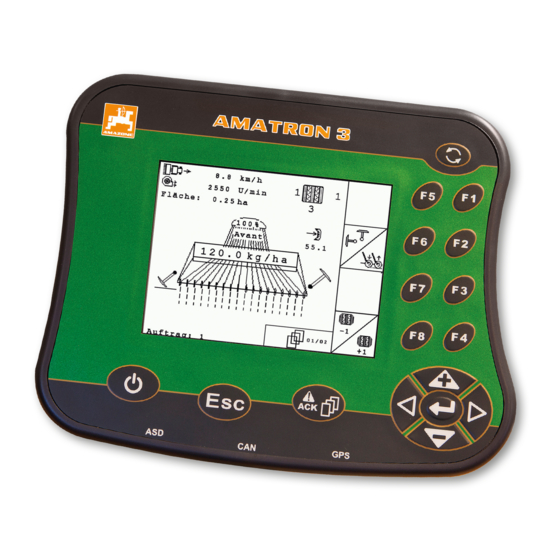
Page 15: Amatron 3 Overview
2 F keys: Press the buttons on the display 5 Escape: Back, cancel 3 Directional pad: Change the selection on the 6 On/Off button: Switching the AMATRON 3 on and display, change numerical values, confirm selections MG5560-EN-II | E.1 | 21.04.2020…
-
Page 16: Rear Side
3 | AMATRON 3 overview Rear side Rear side CMS-T-00004670-A.1 Shift key CMS-T-005609-A.1 1 Shift key for the work menu of the implement controls CMS-I-001943 Rating plate and CE mark CMS-T-005605-A.1 The following information is listed on the rating plate: 1 Implement ID no.
-
Page 17: Basic Operation
4 | Basic operation Basic operation CMS-T-005654-C.1 Using the toggle button CMS-T-001877-B.1 The toggle button 1 can be used to switch among the selected menus. To switch among the selected menus consecutively, press briefly. To switch to the main menu, press and hold.
-
Page 18: Using The F Keys
4 | Basic operation Using the F keys Using the F keys CMS-T-001882-B.1 The arrangement of the keys «F1» to «F8» corresponds to the arrangement of the buttons on the display. When explaining the procedures, this operating manual uses the symbols on the buttons. To execute the procedures, the corresponding F key must be pressed.
-
Page 19: Entering Numerical Values
4 | Basic operation Entering numerical values Text menu overview : Move the curser left and right : Deletes the character in front of the curser : Switch between upper and lower case letters : Shows letters with accents : Clears the input field 1.
-
Page 20: Using The Shift Key
When the shift key is active, it is shown on the display. Press on the rear side of the AMATRON 3. Other function field will be shown, which changes the assignment of the function keys. MG5560-EN-II | E.1 | 21.04.2020…
-
Page 21: After Switching On
5 | After switching on After switching on CMS-T-00004671-A.1 Selecting the BUS mode CMS-T-003915-A.1 After starting the AMATRON 3, it is possible to select between 2 BUS modes. The selection of the BUS mode depends on the connected implement. BUS modes: AMABUS…
-
Page 22: Checking The Aux-N Assignments
The set BUS mode is shown in the main menu CMS-I-002124 Checking the AUX-N assignments CMS-T-003920-A.1 Each time the AMATRON 3 is restarted, the assignment of the external input devices must be checked and confirmed for safety reasons. The AMATRON 3 only recognises external input devices in ISOBUS mode.
-
Page 23: Changing The Aux-N Assignments
5 | After switching on Changing the AUX-N assignments A list of all available functions is opened. The list contains the functions of the AMATRON 3 and the functions of the devices connected. 1. Scroll through the assignment list with…
-
Page 24: Main Menu Overview
6 | Main menu overview Main menu overview CMS-T-003525-A.1 Time and date Selected implement Selected tractor Started job Activated GPS applications with remaining time in hours : Opens the GPS switch. Using the GPS switch, see page 74 : Opens the implement controls. The symbol varies depending on the connected implement.
-
Page 25: Amatron 3 Configuration
1. Select «Setup» > «Settings» > «Basic settings». 2. Enable or disable job management 3. Restart the AMATRON 3. CMS-I-001209 7.1.2 Enabling or disabling ignition switching CMS-T-004834-A.1 This setting defines whether the AMATRON 3 is coupled with the vehicle ignition. MG5560-EN-II | E.1 | 21.04.2020…
-
Page 26: Adjusting The Volume
1. Select «Setup» > «Settings» > «Basic settings». Possible settings: : When the vehicle ignition is switched on or off, the AMATRON 3 is switched on or off. : The AMATRON 3 must be switched on and off manually. CMS-I-002050 2. Enable or disable ignition switching 7.1.3 Adjusting the volume…
-
Page 27: Setting The Brightness
7 | AMATRON 3 configuration Entering the basic settings 7.1.4 Setting the brightness CMS-T-001958-A.1 Select «Setup» > «Settings» > «Basic settings» > «Brightness». CMS-I-001695 Possible settings: : Percent value for the display brightness during the day : Percent value for the display brightness at night : Sets the display brightness to the value entered under «Brightness for operation at night».
-
Page 28: Setting The Date And Time
7 | AMATRON 3 configuration Entering the basic settings 7.1.5 Setting the date and time CMS-T-001969-A.1 Select «Setup» > «Settings» > «Basic settings» > «Date and time». CMS-I-001700 Possible settings: : Day, month and year for the current date : Hours and minutes for the current time…
-
Page 29: Setting The Region And Language
7 | AMATRON 3 configuration Entering the basic settings 7.1.6 Setting the region and language CMS-T-001974-A.1 Select «Setup» > «Settings» > «Basic settings» > «Region and language». CMS-I-002381 Possible settings: : Language for the user interface : Point or comma as a separator for decimal numbers (0.1 or 0,1)
-
Page 30: Configuring Isobus
AMATRON 3, the Task Controller ID must match with the Task Controller ID of the implement. If the AMATRON 3 is the only connected terminal, the implement automatically adopts the Task Controller ID of the AMATRON 3.
-
Page 31: Gps Configuration
7 | AMATRON 3 configuration GPS configuration If an implement is connected to the ASD interface, the TC-ID ASD/GPS maps defines where the incoming data should be sent. To be able to use the ASD interface and GPS maps, the TC-ID ASD/GPS maps must match with the Task Controller ID 5.
-
Page 32
7 | AMATRON 3 configuration GPS configuration NOTE With the SBAS correction signal, a signal with higher accuracy is available as long as the SBAS correction signal is received. SBAS includes the correction services EGNOS, WAAS and MSAS. For more information on this topic, please consult the operating manual for the satellite receiver. -
Page 33: Setting Up The Smart6 Receiver
7 | AMATRON 3 configuration GPS configuration 1. Select «GPS driver» > «AG-STAR/SMART6». 2. Under «Correction signal», select the desired correction signal. 7.3.3 Setting up the SMART6 receiver CMS-T-00000274-A.1 The SMART6 can receive the TerraStar correction signal and therefore offers higher accuracy.
-
Page 34: Setting Up Other Gps Receivers
7 | AMATRON 3 configuration Setting up the ASD interface 7.3.4 Setting up other GPS receivers CMS-T-005821-B.1 1. Select «GPS driver» > «Other». 2. Under «Baud rate», enter the baud rate for the GPS receiver. NOTE More information on the baud rate can be found in the GPS receiver operating manual.
-
Page 35: Adjusting The Light Bar
7 | AMATRON 3 configuration Adjusting the light bar Adjusting the light bar CMS-T-004993-A.1 The light bar 1 shows the deviation of the tractor from the guide track and thereby enables precise following of the guide tracks. 1. Select «Setup» > «Settings» > «Interfaces» > «Light bar».
-
Page 36: Defining The Start Mode
2. Select the menus that should be reached using the toggle button. Defining the start mode CMS-T-001948-A.1 The AMATRON 3 can be started in 3 different modes. Select «Setup» > «Settings» > «Start mode». Possible settings: : The BUS mode can be selected when the AMATRON 3 is started.
-
Page 37: Using Aux-N Input Devices
AMATRON 3 for the GPS functions. Select «Setup» > «Settings» > «Parallel operation». Possible settings: : The AMATRON 3 can be used to access the implement controls and the GPS functions are available. : The AMATRON 3 can only be used to access the implement controls.
-
Page 38
7 | AMATRON 3 configuration Using AUX-N input devices Possible settings: Define the AUX-N assignment using the functions list, see page 32 Define the AUX-N assignment using the input list, see page 33 7.9.1.1 Defining the AUX-N assignment using the functions list CMS-T-002245-A.1… -
Page 39
7 | AMATRON 3 configuration Using AUX-N input devices 7.9.1.2 Defining the AUX-N assignment using the input list CMS-T-002235-A.1 For the AUX-N assignment using the input list, all of the available buttons are listed on the left side. These buttons can be assigned to functions. -
Page 40: Defining The Aux-N Assignment Using The Functions List
7 | AMATRON 3 configuration Using AUX-N input devices 3. Confirm with «Yes». The assignment will be deleted. 7.9.1.4 Deleting all AUX-N assignments CMS-T-002240-A.1 1. Select 2. Confirm with «Yes». The assignment will be deleted. 7.9.2 Defining the AUX-N assignment using the functions list CMS-T-002245-A.1…
-
Page 41: Defining The Aux-N Assignment Using The Input List
7 | AMATRON 3 configuration Using AUX-N input devices If the functions are not listed on the left side: select 2. Select a function from the list. The list of available buttons will be opened. CMS-I-001178 3. Select a button from the list.
-
Page 42: Deleting The Selected Aux-N Assignment
7 | AMATRON 3 configuration Using AUX-N input devices 3. Select a function from the list. The button is assigned to the selected function. CMS-I-001180 7.9.4 Deleting the selected AUX-N assignment CMS-T-005136-A.1 1. Select the desired assignment from the list.
-
Page 43: Deleting All Aux-N Assignments
50 hours. To be able to use the applications without restrictions, the license key must be purchased from AMAZONE. Licence management can be used to activate the 3 applications on the AMATRON 3, to be able to use these applications permanently. MG5560-EN-II | E.1 | 21.04.2020…
-
Page 44
7 | AMATRON 3 configuration Using the licence management The following table shows an overview of the functions that are activated with the licences. Functions GPS switch GPS track GPS maps No licence Setting reference points and calibrating the GPS… -
Page 45: Using The Diagnostics
7 | AMATRON 3 configuration Using the diagnostics 3. Press 4. Enter the license key and confirm. The application is activated. NOTE If the licence keys were accidentally deleted, press to restore them. 7.11 Using the diagnostics CMS-T-00004674-A.1 7.11.1 Using USB management CMS-T-00004700-A.1…
-
Page 46: Using The Pool Management
7 | AMATRON 3 configuration Using the diagnostics REQUIREMENTS Job management enabled; see page 19 select The job data will be saved to the USB flash drive. 7.11.2 Using the pool management CMS-T-001990-A.1 «Pool» refers to a file that describes the representation of the implement software on the terminal.
-
Page 47: Performing A Reset
AMATRON 3 setting can be reset. 1. Select «Setup» > «Setting» > «Diagnosis» > «Reset». To reset the GPS switch settings, Select «Reset GPS switch/track». To reset the AMATRON 3 settings and delete the data, Select «Factory settings». 4. Confirm the reset. CMS-I-002209…
-
Page 48: Configuring Implements
To be able to use the GPS switch functions, the following implements must be configured: AMABUS implements Implements that cannot communicate with the terminal Using the entered implement data, the AMATRON 3 can control the connected implement. The following implement data must be entered: Implement name Implement type…
-
Page 49: Editing The Implement Data
8 | Configuring implements Editing the implement data Select Main menu > «Implements». CMS-I-002180 Implement menu overview Existing implements Information on the selected implement : Opens the main menu : Adds an implement : Deletes the selected implement CMS-I-002213 : Opens the implement data for the selected implement, see page 43 Editing the implement data CMS-T-002023-B.1…
-
Page 50: Editing The Implement Geometry Data
«Implement type». NOTE The implement type can only be selected if the AMATRON 3 was started in AMABUS mode, see page 15. 5. Under «Number of part-width sections», enter the CMS-I-002221 number of part-width sections for the implement.
-
Page 51: Selecting The Implement
8 | Configuring implements Selecting the implement section control, track guidance and variable rate control depend on the correct geometry. 1. Select «Implement data» > «Geometry data». CMS-I-002225 2. Under «X1», enter the distance between the coupling point and the application point. NOTE Application points: Field sprayers: Spray nozzles…
-
Page 52
8 | Configuring implements Selecting the implement AMABUS implement Implements that cannot communicate with the terminal ISOBUS implements sign in to the BUS automatically and do not require configuration. REQUIREMENTS Edit implement data, see page 43 Selectable implements have a check box: Mark the desired implement. -
Page 53: Configuring Tractors
9 | Configuring tractors Configuring tractors CMS-T-00004676-A.1 Managing tractors CMS-T-001903-B.1 For the AMATRON 3 to be able to control the connected implement properly, the data for the utilised tractor must be transmitted to the AMATRON The following tractor data is required: Geometry data…
-
Page 54: Editing The Tractor Data
9 | Configuring tractors Editing the tractor data Select Main menu> «Tractors». CMS-I-002171 Tractor menu overview Available tractors Information on the selected tractor : Opens the main menu : Adds a tractor, see page 48 : Deletes the selected tractor CMS-I-001576 : Opens the tractor data for the selected tractor for editing.see page 48…
-
Page 55: Editing The Tractor Geometry Data
9 | Configuring tractors Editing the tractor geometry data 2. Enter a name for the tractor under «Name». CMS-I-001277 Editing the tractor geometry data CMS-T-002589-B.1 The implement geometry data is required for the GPS switch to function properly. The part-width section control, track guidance and variable rate control depend on the correct geometry.
-
Page 56
9 | Configuring tractors Editing the tractor geometry data If the receiver is installed to the right of the centre of the axle, enter a positive value for the distance between the GPS receiver and the centre of the axle under «A»… -
Page 57: Configuring The Tractor Sensors
The tractor sensor must only be configured if the tractor does not have any speed sensors and therefore does not send speed data. In the case, the speed data can be transmitted to the AMATRON 3 by external sensors, e.g. wheel sensors or GPS sensors. REQUIREMENTS…
-
Page 58: Selecting The Tractor
9 | Configuring tractors Selecting the tractor Selecting the tractor CMS-T-004819-A.1 To use the GPS switch, a tractor must be selected. REQUIREMENTS Tractor data edited, see page 43 Mark the desired tractor. The tractor is selected. CMS-I-001273 MG5560-EN-II | E.1 | 21.04.2020…
-
Page 59: Using The Job Management
GPS switch map. The stored setpoints are transmitted to the implement and processed. When a job has been started on the AMATRON 3, the field boundaries and the application map are displayed on the GPS switch map and the job data is recorded.
-
Page 60
10 | Using the job management Managing jobs REQUIREMENTS Job management is enabled, see page 19 USB flash drive is inserted Main menu > «Jobs». CMS-I-002175 Job menu overview Existing jobs Information on the selected job : Opens the main menu : Opens the master data menu, see page : Adds a job, see page 55 CMS-I-002241… -
Page 61: Editing Jobs
Editing jobs CMS-T-00004679-B.1 10.2.1 Creating a new job CMS-T-002036-B.1 With the AMATRON 3, jobs can be created in ISO- XML format and edited. The created jobs can be exported and further processed with a Farm Management Information System (FMIS). The following additional data can be added to the…
-
Page 62
10 | Using the job management Editing jobs The setpoints for the application/spread rates can come from the following sources: Setpoints created on the AMATRON 3 From an imported application map in shape format From an external device using the ASD interface REQUIREMENTS… -
Page 63
10 | Using the job management Editing jobs 2. Select «Setpoints». The «Setpoints» menu will be opened. The controllable implement elements will be shown. CMS-I-002565 MG5560-EN-II | E.1 | 21.04.2020… -
Page 64: Adding A Worker To A Job
The menu for selecting the setpoint will be opened. The setpoints created in the master data will be shown. NOTE If no setpoints are available, the AMATRON 3 automatically opens the menu for creating a setpoint. In this case, see page 68. CMS-I-001739 4.
-
Page 65
10 | Using the job management Editing jobs REQUIREMENTS Worker is created in the master data, see page 67 Job is started, see page 64 1. Select «Jobs» > Started job. CMS-I-002248 2. select CMS-I-001494 The «Assign worker» menu will be opened. The already assigned workers will be shown. -
Page 66: Adding Implements And Tractors To A Job
10 | Using the job management Editing jobs To add a worker: select 4. Select the desired worker from the list. The selected worker will be added to the job. CMS-I-001747 To start the working time recording for a worker: select To stop the working time recording for a worker:…
-
Page 67
10 | Using the job management Editing jobs REQUIREMENTS Implement is configured, see page 42 Tractor is configured, see page 47 Job is started, see page 64 1. Select «Jobs» > Started job. CMS-I-002082 2. select CMS-I-002324 The «Implement assignment» menu will be opened. -
Page 68: Checking The Map Type
CMS-T-006643-B.1 If a job with an application map in ISO-XML format was imported from the Farm Management Information System to the AMATRON 3, the map type is shown here. Map type 1: The application map is displayed in GPS switch and the setpoints are processed.
-
Page 69: Searching For Jobs
10 | Using the job management Editing jobs 10.2.6 Searching for jobs CMS-T-002043-A.1 1. Select Jobs > 2. Enter the search term. 3. Confirm the entry. The found jobs are displayed. CMS-I-001979 10.2.7 Copying jobs CMS-T-002051-A.1 To process jobs with the same data several times, the jobs can be copied.
-
Page 70: Starting A Job
10 | Using the job management Editing jobs 1. «Jobs» > Select a job. 2. select 3. Confirm the copying. CMS-I-002248 The job will be copied and marked with a «*». CMS-I-001983 10.2.8 Starting a job CMS-T-001583-A.1 When a job is started, the job data is recorded. The field data stored in the job are shown on the map in GPS switch.
-
Page 71: Stopping A Job
10 | Using the job management Editing jobs REQUIREMENTS Job is imported or created: Importing jobs, see page Creating jobs, see page 55 1. «Jobs» > Select a job. 2. select The selected job will be started. CMS-I-001979 10.2.9 Stopping a job CMS-T-001589-A.1 When a job is stopped, the job data is no longer recorded.
-
Page 72: Using Master Data Management
10.3.1 Managing master data CMS-T-00004699-A.1 Master data is additional information that can be created and saved on the AMATRON 3. The created master data can be added to jobs. Master data from a Farm Management Information System (FMIS) cannot be edited.
-
Page 73: Managing Setpoints
10 | Using the job management Using master data management Select «Jobs» > CMS-I-002248 The «Master data» menu will be opened. Possible settings: : Manage the «Setpoints», see page 67 : Manage the «Fields», see page 69 : Manage the «Customers», see page 70 : Manage the «Workers», see page 71 : Manage the «Products», see page 72 CMS-I-001240…
-
Page 74: Editing The Setpoints
10 | Using the job management Using master data management Select «Jobs» > > «Setpoints». Setpoint menu overview : Opens the master data menu : Adds a setpoint : Deletes the selected setpoint CMS-I-001461 10.3.3 Editing the setpoints CMS-T-003930-A.1 Setpoints can consist of several products to document which product was used for the job.
-
Page 75: Managing Fields
10 | Using the job management Using master data management : Line for the total application/spread rate : Line for one product. CMS-I-001465 2. Enter the setpoints for the product in the first column. 3. In the second column, enter the units for the setpoints.
-
Page 76: Editing The Field Data
10 | Using the job management Using master data management Select «Jobs» > > «Fields». : Opens the master data menu : Adds a field : Deletes the selected field : Opens the search function; see page 63 CMS-I-002257 10.3.5 Editing the field data CMS-T-002252-A.1 1.
-
Page 77: Editing The Customer Data
10 | Using the job management Using master data management Select «Jobs» > > «Customers». Customer menu overview Existing customers Information on the selected customer : Opens the master data menu : Adds a customer : Deletes the selected customer CMS-I-002024 : Opens the search function 10.3.7 Editing the customer data…
-
Page 78: Editing Worker Data
10 | Using the job management Using master data management Select «Jobs» > > «Worker». Worker menu overview : Opens the master data menu : Adds a worker : Deletes the selected worker : Opens the search function CMS-I-001500 10.3.9 Editing worker data CMS-T-003415-A.1 1.
-
Page 79: Editing The Product Data
10 | Using the job management Using master data management Select «Jobs» > > «Products». Product menu overview : Opens the master data menu : Adds a product : Deletes the selected product : Opens the search function CMS-I-001305 10.3.11 Editing the product data CMS-T-003475-A.1 1.
-
Page 80: Using The Gps Switch
11 | Using the GPS switch Using the GPS switch CMS-T-006135-D.1 11.1 GPS switch overview CMS-T-00004684-B.1 11.1.1 GPS switch interface CMS-T-00004685-B.1 11.1.1.1 Symbols on the map CMS-T-005238-A.1 CMS-I-002037 MG5560-EN-II | E.1 | 21.04.2020…
-
Page 81
11 | Using the GPS switch GPS switch overview Field boundary warning «GPS» speed Compass Worked area and remaining area Worked area in light green, double-worked areas Obstacle in dark green 10 «Virtual» headlands in grey Tractor symbol and implement symbol 11 Track line with track line number Field boundary in red 12 Mode for the part-width section control… -
Page 82
11 | Using the GPS switch GPS switch overview 11.1.1.3 GPS switch menu CMS-T-005248-B.1 Page 1 : Opens the main menu : Changes between Page 1 and Page 2 starts and stops the recording for a manual implement starts and stops the recording for an ISOBUS or AMABUS implement : Opens the «Field data»… -
Page 83: Gps Switch Functions
When the part-width sections of the connected implement are switched on, the worked area is marked in green on the map of the AMATRON 3. To achieve optimal coverage, the AMATRON 3 can automatically switch the part-width sections of the connected implement on and off.
-
Page 84
11.1.2.2 Track guidance with GPS track CMS-T-004867-A.1 Track lines can be created on the AMATRON 3 to support the driver in working the field seamlessly. After the track lines have been created, they are shown on the map. -
Page 85: Gps Quality Requirements
11 | Using the GPS switch Entering the basic settings for GPS switch 11.1.3 GPS quality requirements CMS-T-006650-A.1 GPS quality 0 to 6 (nominal state) Good DGPS HDOP 6 to 8 Medium HDOP greater than 8 Poor HDOP 0 to 6 Medium HDOP 6 to 8 Poor…
-
Page 86: Select The Source For The Driving Direction Detection
«Turn around direction» function is not available. 11.2.3 Enabling the acoustic field boundary warning CMS-T-003430-A.1 When the vehicle approaches the field boundary, the AMATRON 3 can issue a warning tone. Select «GPS switch» > > «Acoustic field boundary warning». CMS-I-001655…
-
Page 87: Defining The Map Display
11 | Using the GPS switch Entering the basic settings for GPS switch 11.2.4 Defining the map display CMS-T-003405-A.1 The map in GPS switch can be displayed in two or three dimensions. 1. Select «GPS switch» > > «Map display». 2.
-
Page 88: Entering The Gps Switch Settings For Spreaders
This function defines whether a safety zone is automatically created inside a field boundary. REQUIREMENTS For AMABUS spreaders: Spreader is connected The AMATRON 3 is started in AMABUS mode, see page 15 Spreader is selected in the implement menu, see page 45 For ISOBUS spreaders:…
-
Page 89
1 from reaching into the headlands. CMS-I-002104 REQUIREMENTS For AMABUS spreaders: Spreader is connected The AMATRON 3 is started in AMABUS mode, see page 15 Spreader is selected in the implement menu, see page 45 The geometry values for the spreader were… -
Page 90: Entering The Gps Switch Settings For Sprayers
11 | Using the GPS switch Entering the basic settings for GPS switch 11.2.7 Entering the GPS switch settings for sprayers CMS-T-00004682-A.1 11.2.7.1 Setting the automatic boom lowering CMS-T-006124-A.1 The automatic boom lowering automatically lowers the boom when the sprayer moves onto an unworked area.
-
Page 91: Entering The Gps Switch Settings For Seed Drills
Entering the basic settings for GPS switch REQUIREMENTS For AMABUS sprayers: The sprayer is connected The AMATRON 3 is started in AMABUS mode, see page 15 Sprayer is selected in the implement menu, see page 45 Field boundary has been created, see…
-
Page 92
124. REQUIREMENTS For AMABUS seed drills: Seed drill is connected The AMATRON 3 is started in AMABUS mode, see page 15 Seed drill is selected in the implement menu, see page 45 For ISOBUS seed drills:… -
Page 93: Setting The On/Off Point Delays
11 | Using the GPS switch Entering the basic settings for GPS switch 11.2.9 Setting the on/off point delays CMS-T-005059-A.1 When the part-width sections are switched on 1 , it takes a few hundred milliseconds until the application/ spreading actually starts 2 . The switch-on delay 3 can cause underlaps in working the field.
-
Page 94
11 | Using the GPS switch Entering the basic settings for GPS switch On/off point delay for switching off On/off point delay for switching on CMS-I-001618 CMS-I-001810 (A) Length of the overlap Switching off: Entering a worked area Switching on: Moving off a worked area Sprayer: Reduce the on/off point delay Sprayer: Reduce the on/off point delay Seed drill: Increase the on/off point delay… -
Page 95
11 | Using the GPS switch Entering the basic settings for GPS switch REQUIREMENTS AMABUS implement is connected The AMATRON 3 is started in AMABUS mode, see page 15 AMABUS implement is selected in the implement menu, see page 45 1. -
Page 96: Determining The Correction Times For On/Off Point Delays
11 | Using the GPS switch Entering the basic settings for GPS switch 11.2.10 Determining the correction times for on/off point delays CMS-T-006363-C.1 Length of the overlap (A) / Length of the unworked area (B) 0.5 m 1.0 m 1.5 m 2.0 m 2.5 m 3.0 m…
-
Page 97: Checking The Switch-On And -Off Times
REQUIREMENTS ISOBUS implement is connected The AMATRON 3 is started in ISOBUS mode, see page 15 1. In the GPS switch settings, check the values for the «Switch-on time» and for the «Switch-off time».
-
Page 98: Starting The Gps Switch
11 | Using the GPS switch Starting the GPS switch 11.3 Starting the GPS switch CMS-T-00004702-A.1 11.3.1 Starting GPS switch with job management CMS-T-005147-A.1 When job management is enabled, jobs in ISO-XML format can be imported and processed. REQUIREMENTS If GPS switch should be started with job management, the following requirements must be met: GPS is configured;…
-
Page 99
11 | Using the GPS switch Starting the GPS switch TROUBLESHOOTING Are the contents not being displayed on the GPS switch map? The requirements for starting GPS switch have not been met. Error symbols are flashing on the GPS switch map. CMS-I-001543 1. -
Page 100: Starting Gps Switch Without Job Management
11 | Using the GPS switch Starting the GPS switch 11.3.2 Starting GPS switch without job management CMS-T-005152-A.1 REQUIREMENTS If GPS switch should be started without job management, the following requirements must be met: GPS is configured; see page For ISOBUS implements and AMABUS implements: Implement is connected For ISOBUS implements: ISOBUS is configured, see page 24…
-
Page 101: Zooming The Map
11 | Using the GPS switch Zooming the map TROUBLESHOOTING Are the contents not being displayed on the GPS switch map? The requirements for starting GPS switch have not been met. Error symbols are flashing on the GPS switch map. CMS-I-001543 1.
-
Page 102: Panning The Map
11 | Using the GPS switch Panning the map To zoom the map in larger increments, press To zoom the map back to the standard dimensions and to focus on the vehicle symbol, Press 11.5 Panning the map CMS-T-001615-A.1 The map is zoomed and panned with the directional pad.
-
Page 103: Marking Obstacles
11 | Using the GPS switch Marking obstacles When the tractor is driving in reverse, but the tractor symbol is oriented to the front: Select If the tractor is driving forwards, but the tractor symbol is oriented to the rear: Select 11.7 Marking obstacles…
-
Page 104: Deleting An Obstacle Marking
CMS-T-001595-B.1 The AMATRON 3 can create a field boundary from the worked area. Using the field boundary, the AMATRON 3 can calculate the size of the field. The worked area and the remaining area result from the field size. MG5560-EN-II | E.1 | 21.04.2020…
-
Page 105: Deleting The Field Boundary
11 | Using the GPS switch Deleting the field boundary REQUIREMENTS Completely work the field edge «GPS switch» > The field boundary is laid around the worked area. 11.10 Deleting the field boundary CMS-T-004872-A.1 1. «GPS switch» > 2. Confirm deleting. MG5560-EN-II | E.1 | 21.04.2020…
-
Page 106: Managing Virtual Headlands
11 | Using the GPS switch Managing virtual headlands 11.11 Managing virtual headlands CMS-T-00004687-A.1 11.11.1 Creating virtual headlands CMS-T-003520-B.1 REQUIREMENTS Field boundary has been created, see page 98 1. «GPS switch» > 2. Enter and confirm the headland width. A query regarding the headland track line will be shown.
-
Page 107
11 | Using the GPS switch Managing virtual headlands NOTE When the first headland track line is not laid on the field boundary, the first headland track line lies half of the working width away from the field boundary inside the field. If the first headland track line should be laid on the field boundary, Select «Yes»… -
Page 108: Locking Or Unlocking The Headlands
11 | Using the GPS switch Managing virtual headlands 11.11.1.2 Deleting the headland CMS-T-003540-A.1 1. «GPS switch» > 2. Confirm deleting. The headland has been deleted. 11.11.2 Locking or unlocking the headlands CMS-T-003550-B.1 The headlands can be locked or unlocked for application/spreading.
-
Page 109: Using Track Lines
To allow the driver to follow the track lines more easily, the light bar is shown above the map on the AMATRON 3. The light bar shows the length of the track deviation. The light bar can be configured in the GPS switch settings.
-
Page 110
11 | Using the GPS switch Using track lines Available track line Explanation Figure patterns Straight track line that is laid between two points. CMS-I-001478 Straight track line that is laid at a given angle. The specified angle of the track line is relative to the north-south axis. -
Page 111: Defining The Track Line Spacing
11 | Using the GPS switch Using track lines REQUIREMENTS GPS track is activated, see page 37 1. Select «GPS switch» > > «Track line pattern». 2. Select the desired track line pattern and confirm. CMS-I-001987 11.12.2 Defining the track line spacing CMS-T-003465-A.1 The track line spacing is automatically defined as one working width.
-
Page 112: Defining The Light Bar Sensitivity
11 | Using the GPS switch Using track lines worked area must be travelled to create a bed of the desired size. The entered number indicates the rhythm in which the track lines must be followed. If e.g. a 2 is entered, every second track line must be followed.
-
Page 113: Creating Track Lines
11 | Using the GPS switch Using track lines 1. Select «GPS switch» > > «Light bar sensitivity». 2. Enter the length of the required track line deviation and confirm. CMS-I-002086 11.12.5 Creating track lines CMS-T-00004689-A.1 11.12.5.1 Creating an A-B line CMS-T-005582-A.1 REQUIREMENTS «A-B»…
-
Page 114
11 | Using the GPS switch Using track lines 3. Drive to the end of the row. 4. select The end point of the track line is set on the vehicle position. Other track line are added. CMS-I-002054 11.12.5.2 Creating contour lines CMS-T-005572-A.1 REQUIREMENTS «Contour»… -
Page 115: Using Part-Width Section Control
11 | Using the GPS switch Using part-width section control 11.12.5.3 Creating A+ lines CMS-T-005577-A.1 REQUIREMENTS «A+» track line pattern is selected; see page 103 1. Drive to the beginning of the row. 2. select The number area for entering the track line angle will be opened.
-
Page 116
11 | Using the GPS switch Using part-width section control REQUIREMENTS For AMABUS implements and manual implements: The AMABUS implement or manual implement is configured, see page 42 For ISOBUS implements: The ISOBUS implement is connected AMABUS and ISOBUS implements CMS-T-005666-A.1 The recording of the worked areas starts when the part-width sections are manually switched on, and… -
Page 117: Using Automatic Part-Width Section Control
11 | Using the GPS switch Using part-width section control 11.13.2 Using automatic part-width section control CMS-T-00004693-A.1 11.13.2.1 Activating automatic part-width section control CMS-T-006234-B.1 GPS switch can be operated in manual mode and in automatic mode. In automatic mode, the automatic part-width section control is enabled.
-
Page 118
11 | Using the GPS switch Using part-width section control 11.13.2.2 Defining the degree of overlap CMS-T-003425-A.1 The degree of overlap defines the percent by which a part-width section can protrude over a boundary before it is switched off. The set degree of overlap 1 is shown beside the symbol for automatic mode. -
Page 119
11 | Using the GPS switch Using part-width section control Possible settings: Explanation Figure The part-width sections are switched off before any overlap occurs. CMS-I-002003 The part-width sections are switched off when 50 % they half protrude over a boundary. CMS-I-002002 The part-width sections are switched when they… -
Page 120
11 | Using the GPS switch Using part-width section control 1. Select «GPS switch» > «Degree of overlap». 2. Select the percent value and confirm. CMS-I-002265 11.13.2.3 Defining the overlap tolerance CMS-T-003410-A.1 The overlap tolerance defines how far the outer part- width sections can protrude over a worked area before they are switched off. -
Page 121
11 | Using the GPS switch Using part-width section control 11.13.2.4 Defining the overlap tolerance at the field boundary CMS-T-003440-A.1 The overlap tolerance at the field boundary defines how far the outer part-width sections can protrude over the field boundary before they are switched off. Overlap tolerance at the field boundary prevents the outer part-width sections from being constantly switched on and off when driving along and touching… -
Page 122
11 | Using the GPS switch Using part-width section control 11.13.2.5 Defining the overlap in the direction of travel CMS-T-003435-A.1 The overlap in the direction of travel indicates how far the part-width sections can protrude over a boundary in the direction of travel before they are switched off. Overlap in the direction of travel prevents gaps from occurring between the headlands and the rows or between the worked areas. -
Page 123: Managing Field Data
Managing field data CMS-T-00004694-A.1 11.14.1 Saving recorded field data CMS-T-003499-A.1 Field data that was created with the AMATRON 3 can be saved as a recording to a USB flash drive. Saved recordings can be loaded at a later time and used again.
-
Page 124: Loading Field Data From Recordings
The field data will be deleted. 11.14.3 Loading field data from recordings CMS-T-003515-B.1 Recordings are field data files that were created with an AMATRON 3 and saved. The following field data can be loaded: Field boundaries Worked area Track lines…
-
Page 125
11 | Using the GPS switch Managing field data REQUIREMENTS Recordings are available on the USB flash drive 1. Select «GPS switch» > The field data menu will be opened. 2. In the field data menu, select 3. Select «Recording». The saved field data files will be displayed. -
Page 126
11 | Using the GPS switch Managing field data To delete a field data file: Select To search for field data files: Select To show all field data file for fields within a radius: Select NOTE The radius for which the existing field data files are shown depends on the corresponding GPS switch setting, see page 120. -
Page 127: Defining The Radius For Field Detection
11 | Using the GPS switch Managing field data 1. Select «GPS switch» > > «Detect fields (radius)». 2. Enter the radius for field detection and confirm. 11.14.4 Defining the radius for field detection CMS-T-003445-A.1 The field detection radius defines which field data files are shown when field data is imported.
-
Page 128: Loading Field Data From A Shape File
11 | Using the GPS switch Managing field data 11.14.5 Loading field data from a shape file CMS-T-003504-B.1 1. GPS switch > The field data menu will be opened. 2. In the field data menu, select 3. Select «GIS import». 4.
-
Page 129
11 | Using the GPS switch Managing field data 5. Select the shape file and confirm. The selected field data type will be imported. NOTE Imported application maps must be configured, see page 123. 11.14.5.1 Configuring the application map CMS-T-005142-A.1 If «Application maps»… -
Page 130: Configuring The Application Map
11 | Using the GPS switch Using the driver assistance system 11.14.6 Configuring the application map CMS-T-005142-A.1 If «Application maps» was selected when importing the field data, further settings must be entered. 1. Select the values for the application/spread rate. 2.
-
Page 131
At the configured distance from the headland, an additional symbol for the switch point of the implement will be shown. The AMATRON 3 issues two short, low tones. 2. Maintain constant speed. When the additional symbol has reached the headland boundary, the part-width sections are switched off. -
Page 132: Calibrating The Gps Switch
11 | Using the GPS switch Calibrating the GPS switch If the speed becomes irregular before the application/spreading stops, the additional symbol turns red and moves. The AMATRON 3 issues a long, high signal tone. There is overlap or underlap. 11.16 Calibrating the GPS switch CMS-T-00004696-B.1…
-
Page 133: Correcting The Gps Drift With A Reference Point
This point can be driven to at any time to compare the real vehicle position with the position of the virtual reference point on the AMATRON 3. In doing so, it is important to always drive to the reference point in the same way and from the same direction.
-
Page 134: Correcting The Gps Drift Manually
11 | Using the GPS switch Calibrating the GPS switch 11.16.2.2 Starting the calibration CMS-T-003535-A.1 REQUIREMENTS Reference point is set 1. Drive with the vehicle to the real reference point. 2. Mark the reference point in the list. 3. select The calibration is started.
-
Page 135: Using An External Light Bar
11 | Using the GPS switch Using an external light bar 2. Start the manual calibration with The GPS switch map will be shown. CMS-I-001552 3. Move the vehicle symbol using the directional pad. The vehicle symbol will be shifted by the set increment.
-
Page 136
CMS-I-001806 The light bar must have the same baud rate as the AMATRON 3 and the GPS receiver. The light bar is set to a baud rate of 19200 per default. The baud rate can be changed in the light bar configuration menu. -
Page 137: Using The Aux-N Menu
12 | Using the AUX-N menu Using the AUX-N menu CMS-T-003875-A.1 If an external input device is connected, the AUX-N menu can be used to access this input device. The functions within the menu depend on the connected external device. In this operating manual, the AUX-N menu is described based on the AmaPilot 1.
-
Page 138: Eliminating Faults
See the list of signal requirements. Wait for a few seconds and switch on again. AMATRON 3 is switched on and AMATRON 3 cannot be switched on Pull the 9-pin connector out of off too rapidly the basic equipment and plug it in again.
-
Page 139
The AMATRON 3 is not UT no. 1 Make the assignment on another Assignments must always be done and is not responsible for the device or allocate the AMATRON 3 on the terminal with UT no. -
Page 140
13 | Eliminating faults Message Cause Remedy The allocation for this function is Manual assignments to this function pre-defined by the device and it are not permitted. cannot be changed. Delete the pool for the corresponding device, see page 40. Error when loading the pool. -
Page 141: Take Screenshot
14 | Take screenshot Take screenshot CMS-T-00000566-B.1 With a screenshot, an image is made of the displayed software interface and saved as an image file to the USB flash drive. REQUIREMENTS USB flash drive is inserted Press and hold MG5560-EN-II | E.1 | 21.04.2020…
-
Page 142: Indexes
(Automated Field-related Documentation). With the DGPS ASD interface, ASD-compatible data can be imported Differential GPS: Differential global position on the AMATRON 3. This includes e.g. data from determination system. A correction system increases sensors. the precision to +/-0.5 m (0.02 m with RTK).
-
Page 143
Paid system for the correction of satellite data. Field boundary Virtual line on the map of the AMATRON 3. The field boundary marks an area that can be worked. When a field boundary has been created, the AMATRON 3… -
Page 144: Index
GPS maps enabling Customers GPS switch managing calibration enabling resetting Troubleshooting Dead time setting with job management for seed drills without job management Delay time setting GPS track for seed drills enabling Deleting data AMATRON 3 MG5560-EN-II | E.1 | 21.04.2020…
-
Page 145
15 | Indexes INDEX Headland distance Licence key entering Headlands restoring creating deleting 102, 102, 117 Licence management loading from a shape file using loading from recording Licences locking 101, 102 saving Light bar unlocking 101, 102 adjustment Implement controls, opening Main menu Implement controls restarting… -
Page 146
Reference point creation entering the coupling data entering the geometry data Reset Sensors configuration AMATRON 3 GPS switch Tractor symbol rotation Safety zone Universal Terminal troubleshooting Select implement type USB flash drive Self-propelled machine configuration… -
Page 148
AMAZONEN-WERKE H. DREYER GmbH und Co. KG Postfach 51 49202 Hasbergen-Gaste Germany +49 (0) 5405 501-0 amazone@amazone.de www.amazone.de…
Amazone AMATRON 3: Available Instructions
Note for Owners:
Guidesimo.com webproject is not a service center of Amazone trademark and does not carries out works for diagnosis and repair of faulty Amazone AMATRON 3 equipment. For quality services, please contact an official service center of Amazone company. On our website you can read and download documentation for your Amazone AMATRON 3 device for free and familiarize yourself with the technical specifications of device.
-
National Instruments NI CB-37F-HVD
INSTALLATION GUIDENI CB-37F-HVDHigh-Voltage DIN Rail Screw Terminal Block for Rack Mount UsersThis guide describes how to install and use the National Instruments CB-37F-HVD 37-pin D-SUB high-voltage (150 V) DIN rail terminal block. The CB-37F-HVD has screw terminals for connecting up to 37 I/O signals. Use 12–30 AWG wire to connect to the CB-37F-HVD screw terminals.Using the Terminal Block Safe …
NI CB-37F-HVD Touch terminals, 7
-
nvent ZONEX
Hex NutLock Washer, SplitExteriorInteriorO-RingBody GroundingHex NutLockWasher,SplitHG2X 11,02X 11,022-28 in-lbs2.5-3 N-MItems with «HE» at the end of model nameare with horizontal mounting brackets62512-079_DZI Rev.BUser ManualZONEXwww.nVent.com1/4 …
ZONEX Touch terminals, 4
-
Fortec Star MTX-HSPA-PH8-P+G
The information contained in this document has been carefully researched and is, to the best of our knowledge, accurate. However, we assume no liability for any product failures or damages, immediate or consequential, resulting from the use of the information provided herein. Our products are not intended for use in systems in which failures of product could result in per …
MTX-HSPA-PH8-P+G Touch terminals, 70
-
Omron NS —
Cat. No. scee714e2-1 Note: Specifications subject to change without notice.F3SH-A 4-Beam Safety SensorTECHNICAL MANUALCat. No. scee714e2-1Quick Start ManualProgrammable TerminalsNS7-SV00_, NS7-SV01_Cat. No. V081-E2-01Authorised Distributor:Printed in EuropeNS-SeriesNS12-TS00_, NS12-TS01_NS10-TV00_, NS10-TV01_ …
NS — Other, 38
-
Mindeo MS3690
MS3690 (BT) Quick Guide Notice 1) A standard packing includes a terminal, a USB cable and a CD (containing software and electronical manuals). Optional accessory includes a Bluetooth USB adapter BA2110 and an AC/DC adaptor for battery charge. 2) Effective communication range: The communication distance is 30 meters under the condition of temperature at 27 ℃, sunny day, and visibility of 5 kil …
MS3690 Touch terminals, 2
-
COBHAM EXPLORER 540
What’s in the box?To maintain the Ingress Protection of the EXPLORER 540 and to avoid cables accidentally being disconnected, all cable connections are made inside the small compartment at the back of the EXPLORER 540.• Use the provided Torx bit to open the small compartment at the back of the terminal. • Useaatbladescrewdriver(max.2mmwide)topress …
EXPLORER 540 Touch terminals, 2
-
Ingenico group EX8000
WWW.ingenico.com 28-32,Boulevard de Grenelle, 75015 PARIS — FRANCE/ (T)+33(0)1 58 01 80 00 / (F)+33 (0)1 58 01 91 35 Ingenico-SA au capital de 47 656 332 / 317 218 758 RCS Nanterre User Guide Model:AXIUM EX8000 …
EX8000 Touch terminals, 24
-
Intermec Trakker Antares 2420
P/N 064218-005TRAKKER Antares 2400 Series Belt Clip and BeltInstruction SheetThe belt and belt clip allows you to have the TRAKKER® Antares™ 2420 or2425 terminal hang at your side so you can have both hands free. The beltclip snaps around the belt and a Velcro strap holds the terminal to the beltclip. With the terminal at your side, it is easy to reach when you are ready toresume using it.To at …
Trakker Antares 2420 PDA, 2
Popular Touch terminals User Guides:
Терминал управления AmaTron 3

Универсальное применение
Управление всеми важными функциями на Avant может осуществляться через терминал управления AmaTron 3. Сюда относятся рабочие функции, а также функции настройки машины, например, калибровка.
Управление всеми важными функциями на Avant может осуществляться через терминал управления AmaTron 3. Сюда относятся рабочие функции, а также функции настройки машины, например, калибровка.
Сервопривод дозирования на Avant позволяет легко проводить калибровку и индивидуальные изменения нормы высева. Электрогидравлическое управление посредством AmaTron 3 позволяет контролировать режим работы Avant и осуществлять настройку машины.
Терминал управления дополнительно контролирует и регулирует ритмы технологической колеи. Сюда относится также возможность нахождения различных препятствий для маркёров. С помощью нового менеджера задач Task Controller возможна подготовка заданий за офисным компьютером и передача их через USB-накопитель на терминал с последующей обработкой. Посредством AmaTron 3 и Avant можно дифференцированно обрабатывать площади с помощью карт в формате Shape. Импульсы скорости поступают от радара.