-
Contents
-
Table of Contents
-
Troubleshooting
-
Bookmarks
Quick Links
Newport Medical Instruments, Inc.
Newport HT70 Series Ventilator
Service Manual
SERHT70-2 Rev. B
05/14
Newport Medical Instruments, Inc.
1620 Sunflower Ave.
Costa Mesa, CA 92626
0344
Email: venttechsupport@covidien.com
Summary of Contents for Newport Medical Instruments, Inc. HT70
-
Page 1
Newport Medical Instruments, Inc. Newport HT70 Series Ventilator Service Manual SERHT70-2 Rev. B 05/14 Newport Medical Instruments, Inc. 1620 Sunflower Ave. Costa Mesa, CA 92626 0344 Email: venttechsupport@covidien.com… -
Page 2
Page Left Intentionally Blank… -
Page 3
Contact Information Contact Information Telephone: 800-255-6774 option #4 & option #2 Operational Hours: Days: Monday through Friday Hours: 8:00 am to 5:00 pm Emergency After-hours: 24-Hour Clinical and Technical Support Email: venttechsupport@covidien.com Service Center Address: Covidien 2824 Airwest Blvd. Plainfield, IN 46168 Newport Medical Instruments 1620 Sunflower Avenue Costa Mesa, CA 92626, USA… -
Page 4: Table Of Contents
Table of Contents 1 Introduction Brief Device Description …………1-1 Intended Use …………….1-3 Ventilator Configurations …………1-4 Warnings, Cautions, Notes …………1-4 2 Specifications Front Panel Buttons — Symbols Version ……..2-1 Miscellaneous Reference Symbols ……… 2-2 Controls / Monitors …………..2-2 Monitor Data Selections …………
-
Page 5
Table of Contents Air Intake Filter …………….. 4-3 Proximal Inline Filter …………..4-4 Maintenance Guidelines …………4-4 Routine Maintenance …………4-4 6 Month Maintenance …………4-5 12 Month Maintenance …………4-5 24 Month Maintenance …………4-5 15,000 Hour Maintenance ……….4-6 General Warnings ………….. -
Page 6
Table of Contents 6 Performance Verification General Information …………..6-1 Test Equipment ……………. 6-1 Quick Check …………….6-1 Introduction …………… 6-1 Pre-test Inspection …………6-2 Setup and Circuit Check ……….. 6-2 Standard Test Settings …………6-4 Quick Check Procedure …………6-5 Calibration Procedures …………6-8 Introduction …………… -
Page 7
Diagram 8.1 — Pneumatics System ………. 8-1 Diagram 8.2 — Electronics System ……….. 8-2 Diagram 8.3 — HT70 Plus Exploded View …….. 8-3 Diagram 8.4 — Base Assembly ……….8-4 Diagram 8.5 — Case Assembly (1 of 7) ……..8-5 Diagram 8.5 — Case Assembly (2 of 7) ……..8-6… -
Page 8
Page Left Intentionally Blank… -
Page 9: Introduction
Section 1: ntroduction…
-
Page 11
Section 1: ntroduction Brief Device Description ……..1-1 Intended Use …………1-3 Ventilator Configurations ……..1-4 Warnings, Cautions, Notes ……..1-4 OPR360U A0509… -
Page 12
Page Left Intentionally Blank… -
Page 13: Brief Device Description
Sophisticated Clinical Capabilities In addition to its durability and ease of use, the HT70 ventilator offers the complete array of clinical capabilities needed for managing patients.
-
Page 14
Internal Dual Battery System which allows virtually continuous use from battery power through hot-swappable technology. The HT70’s micro-pistons use a fraction of the power that is consumed by turbines and blowers. This enables longer battery use time. Our patented system also uses considerably less supplemental oxygen than turbine or blower systems, again improving mobility for transport or homecare use. -
Page 15: Intended Use
(AC or DC). It can also be charged separately. The HT70 may be operated from a variety of AC (100-240 VAC @ 50 / 60 Hz) or DC (12-24 VDC) external power sources or from the Internal Dual Battery System.
-
Page 16: Ventilator Configurations
Ventilator Configurations Newport Medical offers five configurations for the 3 models in the HT70 family of ventilators. See Table 1. In addition, the front control panel labeling is available in various languages and regional power cords, i.e. North American, European, etc., can be specified. See your Newport Medical Representative for details.
-
Page 17
Do not place liquids on or near the ventilator. Damage can occur if the HT70 is exposed to extreme temperatures. Do not store the HT70 in areas where it may be exposed to temperatures below -40° C (-40° F) or above 65° C (149° F). -
Page 18
OPR360U A0509 When the optional Air/Oxygen Entrainment Mixer is secured in place, ensure that the oxygen supply is enabled prior to powering the HT70 on to avoid putting stress on the internal pump and compromising gas delivery to the patient. -
Page 19
Always plug the HT70 into an external power supply source whenever it is available, even when HT70 is not in use, to keep the Internal Dual Battery System fully charged and to ensure best battery performance. Check battery capacity on the front panel before detaching from external power. -
Page 20
Consult the manufacturer or field service technician for help. Copyright Information © Copyright 2012 Newport Medical Instruments, Inc. All rights reserved. Newport HT70 Ventilator is manufactured in accordance with Newport Medical Instrument, Inc. proprietary information and is protected under U.S. Patent # 7,654,802. -
Page 21: Specifications
Section 2: pecifications…
-
Page 23
Section 2: pecifications Front Panel Buttons — Symbols Version ..2-1 Miscellaneous Reference Symbols ….2-2 Controls / Monitors ……….. 2-2 Monitor Data Selections ……..2-3 Front Panel Membrane Buttons and Indicators ………… 2-4 Alarms …………..2-4 User Adjustable Alarms ……. 2-5 Automatic Alarms ……… -
Page 24
Page Left Intentionally Blank… -
Page 25: Front Panel Buttons — Symbols Version
Specifications Front Panel Buttons — Symbols Version Accept Cancel Alarm Silence Reset / LED Breath Delivery Indicator Brightness Device Alert LED External Power LED Manual Inflation Up/Down Arrow OPR360U A0509 SERHT70-2 B0514…
-
Page 26: Miscellaneous Reference Symbols
Specifications Miscellaneous Reference Symbols Manufacturer Name and Address Authorized Representative in the European community EC REP Main Power Off / On (momentary switch) Low (Paw or Min Vol) alarm High (Paw, Min Vol or RR) alarm Attention, see instructions for use Equipotentiality Applied Parts Type BF Type BF…
-
Page 27: Monitor Data Selections
Specifications Controls / Monitors Range / Selection Resolution I:E Ratio 1:99 to 3:1 0.1 for 9.9:1 to 1:99 and 1 for 99:1 to 1:99 Airway Pressure –10 to 100 cmH O / –10 to 98 mbar Gauge includes indicator bars to show low and high PAW alarm limits Sensor Enabled or Disabled…
-
Page 28: Front Panel Membrane Buttons And Indicators
Specifications Monitor Data Selections P Peak 0 to 100 cmH O /mbar 1 cmH O/mbar P Mean 0 to 100 cmH O /mbar 1 cmH O/mbar P Base (PEEP) 0 to 100 cmH O /mbar 1 cmH O/mbar (Peak) Flow 5 to 150 L/min 0.1 L/min Cylinder time…
-
Page 29: User Adjustable
Specifications User Adjustable alarms Alarm Range / Description Priority P (High Pressure) High 4 to 99 cmH O / 4 to 99 mbar P (Low Pressure) High NIV Off: 3 to 98 cmH O / 3 to 98 mbar (limited by PEEP + 3); 2 breath delay NIV On: 1 to 98 cmH O / 1 to 98 mbar (limited by PEEP + 1);…
-
Page 30
Specifications Automatic alarms Alarm Description Priority Shut Down Alert High Silence by pressing Alarm Silence/Reset button Motor Fault High Hardware detected fault in the motor drive circuit has occurred Internal Temperature Internal temperature is > 60° C Backup Battery Backup Battery temperature is > 60° C Temperature Power Pac Battery Power Pac Battery temperature is >… -
Page 31: Hardware Requirements
PEEP=Ø, max. airway pressure 30 O /mbar, Power Save On, Bias flow Off. NOTE: The Power Pac and Backup batteries are charged whenever the HT70 is connected to an external power source. Battery charge level is best maintained by keeping the HT70 continuously connected to external power.
-
Page 32: Environment
Operating Humidity 15 to 95% non-condensing Operating Altitude Sea level to 15,000 ft (0 to 4,572 m) There is no altitude limitation when HT70 is operated in a pressurized environment. Operating Pressure 600 to 1,100 mbar Storage and Shipping Temperature –40º…
-
Page 33: Factory Default Parameters
Specifications Factory Default Parameters Patient Settings: MODE A/CMV VT (Volume Control) 500 mL i time 1.0 sec 12 b/min Ptrig 2 cmH Paw Alarm 5 cmH Paw Alarm 40 cmH MV Alarm 9 L/min MV Alarm 3 L/min PEEP/CPAP Alarm Loudness Level 6 Miscellaneous Patient Circuit Reusable or disposable 22 mm I.D.
-
Page 34: Regulatory And Agency Standards
Specifications Regulatory and Agency Standards Testing and evaluation of the HT70 Ventilator has been conducted in compliance with the following voluntary standards: ASTM F 1246-91:2005 Standard Specifications for Electrically Powered Home Care Ventilators – Part 1: Positive-Pressure Ventilators and Ventilator…
-
Page 35
Section 3: heory of Operation… -
Page 37
Section 3: heory of Operation Device Description ……….3-1 Functional Subsystems Overview ….3-2 Pneumatics System ……..3-2 Electronics System ……..3-3 Ventilation Functions Overview ……3-7 Modes of Ventilation……..3-7 Breath Types ……….3-10 OPR360U A0509… -
Page 38
Page Left Intentionally Blank… -
Page 39: Theory Of Operation
The HT70 is built for hard work with a durable polymer exterior and robust overall design that stands up to the harsh environments found in the world of emergency response, transport and homecare ventilation.
-
Page 40: Functional Subsystems Overview
Gas delivery to the patient may be enriched with oxygen (.21-1.00) using either the optional Low Flow Oxygen Reservoir or high pressure entrainment mixer. The HT70 has been tested for and meets the requirements for use in a medical evacuation helicopter and fixed wing transport. Functional Subsystems Overview…
-
Page 41: Electronics System
The microprocessor-based design incorporates a Graphical User Interface (GUI), a Single Board Computer (SBC), and the electronics to control the motor/pump, power management, and safety functions of the HT70. Refer to section 8: Diagram 8.2 – Electronics System Diagram. Graphical User Interface (GUI) Subsystem…
-
Page 42
LCD display. The HT70 powers up into a standby condition, in which, there is no patient ventilation occurring. Upon completion of programming the patient settings while in the standby mode, the user can begin patient ventilation by pressing the ‘Start Ventilation’… -
Page 43
Figure 3-2 – Motor and Pump Electronics Electronics Safety Subsystem The HT70 can be brought to a safe state by the SBC microprocessor or independently by discrete hardware. The alarm system is comprised of two separate alarms for clinical alerts and hardware faults. -
Page 44
Figure 3-3 – Electronics Safety Subsystem Power Management Subsystem The HT70 draws power from three sources: external AC or DC power, Power Pac, and Backup Battery. External power to the HT70 is supplied through the Power Pac, The Power Pac electronics arbitrates the power source and sends the data to the Main Control board. -
Page 45: Ventilation Functions Overview
Theory of Operation Figure 3-4 – Power Management Subsystem Ventilation Functions Overview Modes of Ventilation A/CMV Mode (Assist/Control Mandatory Ventilation) In A/CMV mode, time activated (mandatory) breaths are delivered in accordance with the RR setting. Patients can trigger mandatory breaths in addition to, or in place of, time activated (mandatory) breaths if the effort they generate causes airway pressure to meet the Ptrig or Flow trigger setting.
-
Page 46
HT70 operating modes, Backup Ventilation is activated if the BUV linked alarm is violated. (Non Invasive Ventilation) The HT70 can be used for noninvasive ventilation in all modes. Press the NIV button on the left side of the touch screen to toggle ON noninvasive. -
Page 47
Theory of Operation Backup Ventilation Backup Ventilation activates when the currently linked alarm occurs. This function can be linked with the Low Minute Volume (MV ) alarm, the Apnea alarm, or both alarms. During Backup Ventilation the linked alarm(s) will sound and the message window will indicate that Backup Ventilation is in use. -
Page 48: Breath Types
HT70 resumes ventilation at the user-selected parameters. Breath Types (Pressure Control Ventilation) The HT70 targets and maintains patient airway pressure at the set pressure control level throughout inspiration. Breath termination occurs when (1) the set i time elapses, or (2) Paw exceeds the Pressure Control setting by 8 cmH O (mbar).
-
Page 49
Theory of Operation (Volume Control Ventilation) During Volume Control ventilation, tidal volume can be set for mandatory breaths. If a volume setting is changed while the ventilator is operating, the change takes place in increments over a series of breaths. When tidal volume is adjusted, inspiratory time remains constant and mandatory flow changes. -
Page 50
Page Left Intentionally Blank… -
Page 51
Section 4: leaning and Maintenance… -
Page 53
Section 4: leaning and Maintenance Cleaning and Disinfecting ………4-1 Ventilator …………4-1 Accessories …………4-2 Low Flow Oxygen Reservoir ……4-2 Air/Oxygen Entrainment Mixer …..4-2 Reusable Breathing Circuits ……4-3 Air Intake Filter ……….4-3 Proximal Inline Filter ……… 4-4 Maintenance Guidelines ……..4-4 Routine Maintenance …….. -
Page 54
Page Left Intentionally Blank… -
Page 55: Cleaning And Maintenance
Cleaning and Maintenance Cleaning and Disinfecting Use the information in this section in conjunction with hospital policy, physician prescription, Homecare Dealer or accessory manufacturer instructions. Definitions Cleaning: A process that uses a medical detergent or alcohol based cleaning solution to remove blood, tissue and other residue. Rinse thoroughly with sterile, distilled water and allow to air dry.
-
Page 56: Accessories
Disassembly from the HT70 ventilator: Remove the Oxygen Reservoir from the HT70 Fresh Gas Intake port. Disconnect the oxygen tubing. General Cleaning Instructions: Hold the Low Flow Oxygen Reservoir in both hands and twist the top counterclockwise to disassemble.
-
Page 57: Reusable Breathing Circuits
Cleaning and Maintenance Reusable Breathing Circuits and Exhalation Valves The HT70 ventilator may be used with a standard single limb or “J” style breathing circuit with a quality exhalation valve. Reusable breathing circuits and exhalation valves are generally provided in clean, but not sterile, condition. Follow the manufacturer’s instructions to clean and/or disinfect prior to use.
-
Page 58: Proximal Inline Filter
Cleaning and Maintenance WARNING NEVER operate the HT70 without a clean Air Intake Filter in place. NEVER reverse the Air Intake Filter when dirty. Proximal Inline Filter (p/n HT6004701 or equivalent) Check the Proximal (Prox) Inline Filter weekly and replace it at least every 3 months.
-
Page 59: Month Maintenance
1. Whenever possible, plug into external power source to charge the batteries. 2. Use the optional DC Auto Lighter Cable accessory to power the HT70 when traveling by automobile or to connect to an external battery. See Section 7 of the Operations Manual, Battery Operation for more information on the proper operation of the HT70 Internal Dual Battery System.
-
Page 60: 15,000 Hour Maintenance
3 Calibration and OVP performed by Authorized Service Provider 15,000 Hour Maintenance 3 A comprehensive maintenance should be performed after 15,000 hours of operation. Refer to the HT70 Service Manual, or contact the Newport Medical Technical Service Department for detailed information on the 15,000 Hour Maintenance.
-
Page 61: Factory Maintenance Or Repair
Cleaning and Maintenance Factory Maintenance or Repair An authorized Newport Medical Instruments factory-trained technician must do all service or repairs performed on the HT70. Caution: Always disconnect the external power supply prior to servicing. Scheduled maintenance or repair services are available from the Newport Technical Service Department.
-
Page 62
Page Left Intentionally Blank… -
Page 63
Section 5: ervice and Repair… -
Page 65
Section 5: ervice and Repair General Information ……….. 5-1 Tools Required ………… 5-1 Removal and Replacement of the Rear Panel Assembly ……….5-2 Rear Panel Assembly ……..5-2 Single Board Computer (SBC) Assembly ..5-4 Main Control Board (MCB) Assembly ..5-5 Power Switch Assembly …….5-6 Removal and Replacement of Top Case Assembly ………… -
Page 66
Speaker Assembly ……..5-17 Solenoid Valve Group Assembly ….5-18 On/Off Valve ……….5-20 Safety Valve ……….5-20 Pump Assembly ………..5-20 Manifold Assembly ……..5-22 OPR360U A0509… -
Page 67: Service And Repair
Unless otherwise instructed, reinstall the assemblies, subassemblies, and components by reversing the disassembly procedure. Prior to servicing the HT70, be sure to do the following: 1. Disconnect from external power. 2. Disconnect oxygen (O ), if applicable.
-
Page 68: Removal And Replacement Of The Rear Panel Assembly
Assembly Including associated assemblies Rear Panel Assembly 1. Disconnect the power cord PWR3204P from the HT70. 2. Press the release latch and remove the Power Pac BAT3271A. Figure 5.1 Power Pac Removal 3. Using a #1 Phillips screwdriver, remove the nine (9) outside screws on the rear panel.
-
Page 69
Service and Repair 4. Carefully slide the rear panel back to expose the cable harnesses and pneumatic tubes connected to the Main Control Board (MCB). 5. Disconnect the following cables from the MCB: J8, J16, J22, J26 J35 and J42. GR-CBL3214A Backup Battery GR-CBL3208A… -
Page 70: Single Board Computer (Sbc) Assembly
Service and Repair J800 SBC Figure 5.5 SBC and MCB Connections 8. Disconnect the remaining cables on the MCB: J28, J36, J38, and J39. 9. Lay the rear panel on the work surface. Single Board Computer (GR-PCB3207A) Assembly 1. Using a #1 Phillips screwdriver, remove the four (4) screws (SCR3274P) and washers (WSH1512P) securing the SBC EMI shield (PLT3270M).
-
Page 71: Main Control Board (Mcb) Assembly
1. Perform above steps for removal of Single Board Computer (SBC) assembly. 2. When ordering the SBC be sure to order GR-105795 for the Plus Units and GR-105796 for the HT70-2. 3. Disconnect the Power Pac Battery Connector Board cable (GR-PCB3203A) from J5 on the MCB.
-
Page 72: Power Switch Assembly
Service and Repair 6. Using a #1 Phillips screwdriver, remove the four (4) screws (SCR3210P) securing the MCB. SCREWS Figure 5.9 MCB Screws 7. Reverse the above steps to reinstall. Power Switch Assembly (SWI3204P) 1. With the rear panel removed, use a small flat screwdriver to carefully press the locking tabs against the sides of the power switch.
-
Page 73: Removal And Replacement Of Top Case Assembly
Service and Repair on the left side of the switch and the red wire is on the right side. The ON position faces to the right, looking from the rear of the HT70 3. Reverse the above steps to reinstall.
-
Page 74: Fan Filter And Guard
NMI part number ADH110P. Apply the adhesive to the rear surface of the gasket avoiding the slotted areas. Align the tab in the gasket with the slot on the HT70 and press firmly and allow curing overnight before returning to service.
-
Page 75: Top Case Assembly
6 – 8 in-lb Top Case Assembly (CVR3250A) 1. Refer to the Rear Panel Assembly section to remove the rear OPR360U A0509 panel. 2. Lay the HT70 on the left or right side to expose the screws on the bottom plate. SERHT70-2 B0514…
-
Page 76
(SCR3210P) securing the muffler located on the left side when OPR360U A0509 facing the rear of the HT70. Remove the muffler and gasket. 7. Carefully lift the rear portion of the top case Assembly. Ensure the fan clears the pump assembly. -
Page 77: Fan Assembly
9. Reverse the above steps to reinstall. Note: When reinstalling the muffler, ensure the gasket (GKT3206M) is between the muffler and the inside of the HT70. Fan Assembly (GR-CBL3208A) 1. Using a short #1 Phillips screwdriver, remove the four (4) screws…
-
Page 78: Display Board
Service and Repair Figure 5.19 – Backup Battery 2. Remove the backup battery. 3. Install the gasket (GKT4408P) on the bottom, opposite end from the wire harness, of the battery pack. If the gasket on the bracket has come off, replace with a new gasket.
-
Page 79: Chassis Assembly
Service and Repair LCD back light 2 wire connector on J7 — (Under J3) INV3201A from touch screen panel PNL3205P J5 — Inverter cable Figure 5.20 – Display Board Chassis Assembly (GR-BSE3251A) 1. Using a #1 Phillips screwdriver, remove the two (2) screws (SCR3215P) securing the ground strips for the left and right switch membranes and use a 3/16”…
-
Page 80: Buzzer Assembly
Service and Repair Figure 5.21 Buzzer Assembly (GR-CBL3210A) 1. Located on the front side of the chassis assembly, turn the securing mounting ring counter-clockwise to loosen and remove the buzzer cable assembly. 2. Be sure to take notice of the position of the silicon o-ring on the buzzer.
-
Page 81: Handle Assembly
Service and Repair Note: The LCD display and Touch Screen must be replaced as a whole assembly including the LCD gasket. (GKT3208M, PNL3205P and DSP2105P) Remove 4 screws (2 each side) securing display to chassis Figure 5.23 LCD Touch Screen Display 3.
-
Page 82: Membrane Switch Assemblies
Service and Repair Remove 4 screws (2 each side) securing the handle to cover assembly Figure 5.24 Handle Removal Membrane Switch Assemblies 1. Using a small flat screwdriver, carefully remove the Right (MEM3210M), Top (MEM3212M), or Left (MEM3211M) Membrane Switch assemblies. 2.
-
Page 83: Removal And Replacement Of The Base Assembly
Service and Repair Before installing a new membrane, clean the surface of the cover assembly to remove any adhesive. Figure 5.25 Membrane removal and replacement Removal and Replacement of the Base Assembly Including associated assemblies Refer to the Rear Panel Assembly and the Top Case Assembly sections for removal of the rear panel and top case.
-
Page 84: Solenoid Valve Group Assembly
Service and Repair Note: Under the speakers, there is a gasket (SEL3201M). Before replacing speaker assembly, ensure the gasket is installed. Note: Both speakers must be replaced when replacing either speaker. Solenoid Valve Group Assembly (GR-SOL3250A) 1. Refer to Figure 5.27 and 5.28 for the following steps. Solenoids P/N VLV3226M Solenoids P/N…
-
Page 85
3. Disconnect the Auto-zero Solenoid green tube from the ‘G’ port connection on the manifold. 4. From the bottom of the base assembly, remove the 4 screws p/n SCR3215P securing the solenoid plate p/n PLT3276M to the HT70 base. 5. Remove the plate. To replace any of the four solenoids… -
Page 86: On/Off Valve
Service and Repair On / Off Valve (VLV3225M) 1. Remove the clear tube from the top of the on/off valve. 2. From the bottom of the base assembly, remove the 2 screws (SCR3219P) securing the on/off valve. Install the new on/off valve and secure with the 2 screws removed.
-
Page 87
Service and Repair Remove Qty 2 Screws SCR3232P Remove Qty 4 Screws SCR3219P Figure 5.29 – Pump/Manifold Screws OPR360U A0509 Figure 5.30 Base Plate 5-21 SERHT70-2 B0514… -
Page 88: Manifold Assembly
Service and Repair Manifold Assembly (MNF3200A & GR106764) 1. Refer to the Solenoid Valve Removal section for regarding the disconnection of the pneumatic tubes. 2. Refer to Figure 5.29, Pump Assembly Removal, regarding the removal of the pump assembly from the base plate. 3.
-
Page 89
Service and Repair Note: When reinstalling the Proportional solenoid valve to the manifold and the manifold to the pump assembly, ensure the o-rings (ORG200P) are fully seated to avoid any possible damage to the o-rings. Note: The gasket (GKT3254M) is installed over the gas outlet and Prox and Exh fittings. -
Page 90
Page Left Intentionally Blank… -
Page 91
Section 6: erformance Verification… -
Page 93
Section 6: erformance Verification General Information ……….. 6-1 Test Equipment ……….. 6-1 Quick Check …………6-1 Introduction ………… 6-1 Pre-test Inspection ……..6-2 Setup and Circuit Check …….6-2 Standard Test Settings ………6-4 Quick Check Procedure ……..6-5 Calibration Procedures……..6-8 Introduction …………6-8 Equipment Setup ………..6-8 Pressure Transducer Calibration ….6-8 Motor Speed Calibration …… -
Page 94
AC Power Loss and Shutdown Buzzer Alarm Test ………… 6-14 Circuit Check ……….6-14 LED/Solenoid Check ……..6-15 Pressure Relief Valve Test ……6-17 Pressure Verification Test ……6-18 System Leak Test ……..6-18 Flow Measurement ……..6-19 Emergency Intake Valve Test ….. 6-19 Patient Effort Indicator Test ……. -
Page 95: Performance Verification
6 months. HOMECARE PROVIDERS: This procedure should be performed prior to delivery of the HT70 to a patient’s home and every 6 months. OPR360U A0509 NOTE: If Power Save is On, the screen will go to sleep (go blank) when not used for two minutes.
-
Page 96: Pre-Test Inspection
Performance Verification WARNING Do not use the HT70 if it fails the Quick Check Procedure. Pre-test Inspection 1. Inspect the Air Intake Filter through the filter cover on the right side of HT70. Replace the filter if it is dirty.
-
Page 97
Then touch the Circuit Check button to redo the test. WARNING Do not use the HT70 if the Circuit Check fails, inadequate ventilation may result. Use an alternate method of ventilation. Contact Newport Medical Technical Support. -
Page 98: Standard Test Settings
Performance Verification STANDARD TEST SETTINGS (STS) Parameter Patient Setting Advanced/ More Screen Flow Wave Square Pattern Slope/Rise PS Exp Thresh PS Max i-Time Alarm Screen 3 cmH O / mbar (Low Airway Pressure) 99 cmH O / mbar (High Airway Pressure) hMin Vol 50 L (maximum setting)
-
Page 99: Quick Check Procedure
1) No External Power Alarm Check a) Disconnect the A.C. power adapter. Verify that there is an audible alarm and the alarm LEDs in the HT70 handle turn on. Verify that the Ext. Power LED turns off, and the Message Area turns yellow and displays the No External Power alarm message.
-
Page 100
80%. If battery charge level is not sufficient, plug into external power to fully charge the Integrated Battery System. b) Remove the Power Pac battery pack. Verify that HT70 continues to ventilate, the alarm sounds, the alarm LEDs light and the message in the message area indicates that the Backup Battery is in use. -
Page 101
Performance Verification HT70 Ventilator Quick Check Record Pass / Fail Check-Off Sheet Preparation for Use Tests Test Results 1. No External Power Pass _____ Fail ______ Alarm Check 2. Alarm & Indicators Check High Paw Pass_____ Fail _____ Low Paw Pass _____ Fail ______ 3. -
Page 102: Calibration Procedures
Equipment Setup 1) Plug the HT70 into AC power and leave powered off for 30 minutes prior to testing to ensure the ventilator has sufficient power to complete the calibration testing.
-
Page 103
Performance Verification Figure 6.3 – Calibration Screen 3) Disconnect the luer-lock on the Yellow tubing connected to the Airway Pressure Transducer (XD2) mounted to the Main Control Board PCB. a) Select ‘Start Paw Cal’ to zero the reading. Note: The Message ‘Apply zero pressure to the Airway Pressure Transducer. -
Page 104
Performance Verification Connector Main Control Board Transducers (XD1 & XD2) Locking Pressure Syringe Refer to Figure 6.4 – Transducer Calibration 5) Adjust the syringe and monitor the analyzer until a pressure of 60±0.02 cmH O is achieved. When the reading is stable, press the “Pressure Ready”. -
Page 105: Motor Speed Calibration
“Cancel Cal”. 12) Reconnect the luer-lock to XD2 and XD22 transducer pressure tubes. 13) Power the HT70 off and Rreassemble the Rear Panel Assembly and reinstall the Power Pac removed in step 21. Renter calibration screen as performed in step 2.
-
Page 106: Fio 2 Sensor Calibration
Upon completion, the ventilator will state ‘O 100% Ready’. 3) Connect the HT70 Low Flow Oxygen Reservoir to the ventilator. 4) Connect the O gas source to your flow meter. (note: make sure the flow meter adjustment knob is in the off position.) 5) Turn on the oxygen source and turn the flow meter up to 10 L/min to flush the reservoir.
-
Page 107: Operational Verification Procedure (Ovp)
DC power from the AC/DC power supply. Equipment Setup OPR360U A0509 1) Plug the HT70 into AC and leave off for 30 minutes prior to testing to ensure the ventilator has sufficient power to complete the calibration and testing.
-
Page 108: Front Panel Test
Performance Verification 2) Connect a patient circuit and test lung to the HT70 as shown in Figure 6.2. Front Panel Test 1) Press the On/Off switch once. The ventilator performs a self-test. During the self-test, verify that no error messages are displayed.
-
Page 109: Led/Solenoid Check
1) Turn on the ventilator and hold “cancel” until the Service screen comes up – Figure 6.5. Figure 6.5 – Service Screen for the HT70 Classic OPR360U A0509 Figure 6.6 – Service Screen for HT70 Plus and HT70-2 Models 6-15 SERHT70-2 B0514…
-
Page 110
Performance Verification 2) Then select Digital Outputs/Monitors Figure 6.7 – Digital Inputs & Outputs for HT70 Plus and HT70-2 3) Then use the touch screen to activate and deactivate each item below to verify operation: • Red and Yellow LED – The red and yellow indicators activate •… -
Page 111: Pressure Relief Valve Test
Performance Verification Figure 6.8 – Motor Control Screen for HT70 Plus and HT70-2 6) Use the touch screen to activate and deactivate each item below to verify operation: • Exhalation Valve – Listen for the solenoid click • Relief Valve – Listen for the solenoid to click •…
-
Page 112: Pressure Verification Test
Performance Verification b) Verify all air leakage must be from the pressure relief valve. 6) Select the ‘Enable Motor’ to deactivate the motor. 7) Remove the blue cap. Pressure Verification Test 1) Continue in the Service screen for the Pressure Verification Test. 2) Attach the breathing circuit to the ventilator and connect the T-connector from a calibrated pressure analyzer to the patient connection.
-
Page 113: Flow Measurement
1) With the ventilator off, attach a test lung (LNG600P) to the Main Flow Outlet. Note: Test lung needs to be deflated and squeezed before connecting to the HT70. 2) Verify air can be pulled through the emergency intake valve by gently squeezing the test lung and creating a negative effort (vacuum) in the HT70.
-
Page 114: Pressure Control And Peep Test
Performance Verification 2) Touch the “Start Ventilation” on the touch screen. 3) Set RR to1 b/min and trigger breaths by squeezing the test lung hard enough to create a negative pressure equal to or greater than 1 cmH O/mbar. Note: Negative efforts are displayed by a yellow bar on the graph. 4) Verify the Patient Effort Indicator (on touch screen) blinks and the ventilator delivers a mandatory breath every successful squeeze of the test lung.
-
Page 115: Fio 2 Verification Test
Record the Displayed and Measured values on the Test Record a) Set flow meter to 3 LPM, Verify both the HT70 and Calibrated O2 analyzer are within 3% of each other. b) Set flow meter to 5 LPM, Verify both the HT70 and Calibrated O2 analyzer are within 3% of each other.
-
Page 116: Manual Inflation Test
550 mL. 4) Connect the expiratory flow sensor to the circuit and record the values on the Test Record (only for HT70 Plus Units) a) VT 200mL / Flow 30 / iTime 0.4s / RR 10 bpm. Spec: 180 –…
-
Page 117
Performance Verification a) Verify the Low Pressure alarm is activated. b) Verify the Red LED indicators are activated. c) Verify the message ‘Low Pressure’ is displayed. 4) Return the alarm settings to the STS. 5) Disconnect the individual limbs of the patient circuit and verify the appropriate alarm is activated. -
Page 118: Integrated Battery System Check
Verify the HT70 continues to ventilate. b) Verify the audible alarm and handle alarm indicators activate. c) Verify the HT70 displays ‘No Ext Power / Switching to Battery Power’. d) Verify the battery level indicator has changed to blue and the power level indicates at least 80%.
-
Page 119: Troubleshooting
Section 7: roubleshooting…
-
Page 121: Table 7.1 Troubleshooting Guide
Section 7: roubleshooting Table 7.1 Troubleshooting Guide …….7-1 OPR360U A0509…
-
Page 122
Page Left Intentionally Blank… -
Page 123
This troubleshooting guide is intended to assist a Newport Medical factory-trained and authorized technician to troubleshoot and repair the HT70 Ventilator. Although the table will be advantageous during the evaluation of the problem, all issues may not be addressed. The guide includes Mechanical, Pneumatic and Electronic troubleshooting. -
Page 124
Troubleshooting Problem Potential Cause Corrective Action Low proximal Pressure relief Perform the Pressure Relief Valve pressure (P valve leaking Check in the OVP section. If the with normal failure persists, contact Newport output flow Medical Technical Support for further assistance. cont. -
Page 125
Check patient for proper connection and compliance Note: If using a star lumen tubing, make sure the tubing is not connected directly to the HT70 Internal solenoid Check the internal tubes and verify all valve or valve are securely connected… -
Page 126
Troubleshooting Problem Potential Cause Corrective Action Proximal Kinked or Check and replace the inline proximal pressure has occluded filter if necessary slow return to proximal baseline pressure Heat Moisture Exchanger (HME) is line causing resistance during exhalation . Remove or change the HME Pump louder Large leak in the Check and replace patient circuit if… -
Page 127
Troubleshooting Problem Potential Cause Corrective Action Does not Power Pac Connect to AC and charge for at least operate on discharged 3 hours Power Pac Power Pac will Replace the Power Pac battery not charge Replace the Power Pac older than two (2) years Power Pac battery Main Control… -
Page 128
Troubleshooting Problem Potential Cause Corrective Action Touch Screen Loose Remove the rear panel and case unresponsive connection assemblies and inspect the cables for proper connections on the display board Damaged cables Replaced the LCD display assembly Main Control Replace the Main Control board board malfunction Single Board… -
Page 129
Troubleshooting Problem Potential Cause Corrective Action Device Alert Motor Fault error Refer to the displayed message LED on window or Event History log for Internal Pressure additional information (Pint) error System Error Motor Fault Pump assembly Replace Pump assembly malfunction Main Control Replace Main Control board board… -
Page 130
Page Left Intentionally Blank… -
Page 131
Section 8: iagrams and Assembly Part Lists… -
Page 133: Diagram 8.1 — Pneumatics System
Diagram 8.1 — Pneumatics System ….8-1 Diagram 8.2 — Electronics System ….8-2 Diagram 8.3 — HT70 Plus Exploded View ..8-3 Diagram 8.4 — Base Assembly ……8-4 Diagram 8.5 — Case Assembly (1 of 7) ….. 8-5 Diagram 8.5 — Case Assembly (2 of 7) …..
-
Page 134
Page Left Intentionally Blank… -
Page 135
XD3, DIFFERENTIAL PRESSURE CONTROL BOARD XD1, AIRWAY PRESSURE AIRWAY PRESSURE AIR FILTER XD2, VALVE SAFETY VALVE MOTOR DRIVE DRIVE PRESSURE AUTO ZERO VALVES INTERNAL PRESSURE VALVE PUMP AIRWAY FLOW SENSOR O2 MIXER AIR FILTER MUFFLER OUT IN HIGH PRESSURE RELIEF VALVE PROPORTIONAL VALVE EMERGENCY AIR… -
Page 136: Diagram 8.2 — Electronics System
COOLING OXYGEN EXT BAT INT BAT SENSOR GR-CBL3214A GR-CBL3200A GR-CBL3208A GR-CBL3403A SPKRS GR-PCB3212A HT70P ADD-ON TRANSDUCER BOARD FLOW SENSOR DISPLAY Oxygen EXT BAT INT BAT GR-PCB3403A GR-PCB3404A BYPASS BOARD FLOW SENSOR BOARD ..MEM_TOP DISPLAY ..SBC BOARD CONTROL BOARD ..
-
Page 137: Diagram 8.3 — Ht70 Plus Exploded View
GR-PCB321a waSHER, FlaT, .115 ID x .250 oD x .062 THk, nylon wSH1020P 11 2X CaBlE TIE HolDER, 3/4” l x 3/4” w x 3/16” H CTH100P 33 4X 30 4X Diagram 8.3 — HT70 Plus Exploded View SERHT70-2 B0514…
-
Page 138: Diagram 8.4 — Base Assembly
SolEnoID aSSEmBly, HT70 PluS Sol3250a PumP anD manIFolD aSSEmBly, nExT GEn GR-PmP3230a nylon CaBlE TIE TyR3201P CaBlE, aSSy ValVE, HT70 PluS GR-CBl3231a SCREw, 6-32 x 3/8” PH Pan Sq ConE SEm SS SCR3219P SCREw 2-56 x .250, Pan HEaD PHIl, SST SCP2025P…
-
Page 139
SCREw 4-40 x 5/16” PH Pan Sq ConE SEmS SS SCR3216P SCREw 4-40 x 1/4” PH Pan Sq ConE SEmS SS SCR3215P SCREw, 4-40 x 3/4” Pan HD, PaTH SCR3277P Diagram 8.5 — HT70 Plus Case Assembly (1 of 7) SERHT70-2 B0514… -
Page 140
TaPE, kaPTon, PolymIDE, 1/2” TaP077P waSHER, SPRInG loCk #4, S.S. wSH3207P nuT, HEx 4-40 THD, S.S. nuT2107P SCREw, 4-40 x .25”, 100 DEG FlaT HEaD PHIllIPS, 300 SS SCR3210P Diagram 8.5 — HT70 Plus Case Assembly (2 of 7) SERHT70-2 B0514… -
Page 141
SCREw 4-40 x 5/16” PH Pan Sq ConE SEmS SS SCR3216P SCREw 4-40 x 1/4” PH Pan Sq ConE SEmS SS SCR3215P aDHESIVE, ClEaR Two PaRT aDH111P GaSkET, HouSInG CEnTER BoTTom GkT3253m aDHESIVE, RTV SEalanT aDH108P Diagram 8.5 — HT70 Plus Case Assembly (3 of 7) SERHT70-2 B0514… -
Page 142
Item Qty. Description Part No. 4.5” GaSkET, EmI SHIElDInG GkT3214m SCREw 4-40 x 5/16’ PH Pan Sq ConE SEm SS SCR3216P 9 In TaPE, kaPTon PolymIDE, 1/2” TaP077P Diagram 8.5 — HT70 Plus Case Assembly (4 of 7) SERHT70-2 B0514… -
Page 143
ClEaR Two PaRT aDH111P 4X 39 SCREw 4-40 x 5/8”, PH Pan Sq ConE SEmS SS SCR3218P CoVER uSB CuTouT CVR3256m 3” GaSkET CoRD, .125 oD, SIlIConE SPonGE GkT3250P Diagram 8.5 — HT70 Plus Case Assembly (5 of 7) SERHT70-2 B0514… -
Page 144
BRaCkET, BaTTERy BkT3214m SCREw 4-40 x 5/16” PH Pan Sq ConE SS SCR3216P SCREw 4-40 x 1/4’ PH Pan Sq ConE SS SCR3215P aDHESIVE, ClEaR Two PaRT aDH111P Diagram 8.5 — HT70 Plus Case Assembly (6 of 7) 8-10 SERHT70-2 B0514… -
Page 145
HEx nuT, 4-40 THD, 3/16” w, 1/16” H, SST nuT3207P 6” GaSkET, 1/4 x 3/4 aDHESIVE BaCkED Foam GkT3209P 40 2X 30 2X 40 2X Diagram 8.5 — HT70 Plus Case Assembly (7 of 7) 30 2X 8-11 SERHT70-2 B0514… -
Page 146
Page left Intentionally Blank…

> Запросить цену! <
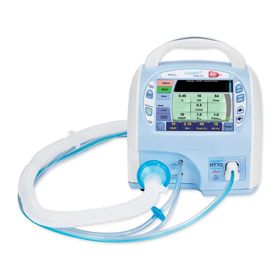
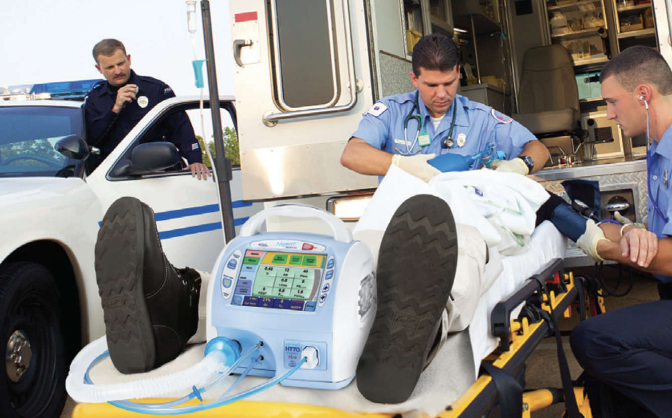
Портативный аппарат ИВЛ Newport HT70 Plus – сочетает прочность и легкость в использовании c исключительной мобильностью для пациентов от 5 кг. Прибор подходит как для домашнего применения, так и для транспортировки пациентов, вентиляции пациентов в больницах и долгосрочного ухода.
- Описание
- Производитель
- Отзывы (0)
- Доставка
- Файлы (3)
Описание
Описание ИВЛ HT70
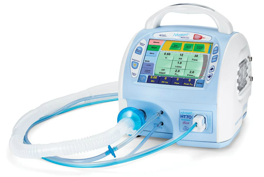
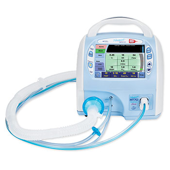
Цветной сенсорный экран аппарата ИВЛ Newport™ HT70 Plus обеспечивает простую и удобную настройку параметров мониторинга и вентиляции. Сигналы тревог имеют цветовую кодировку для быстрого распознавания.
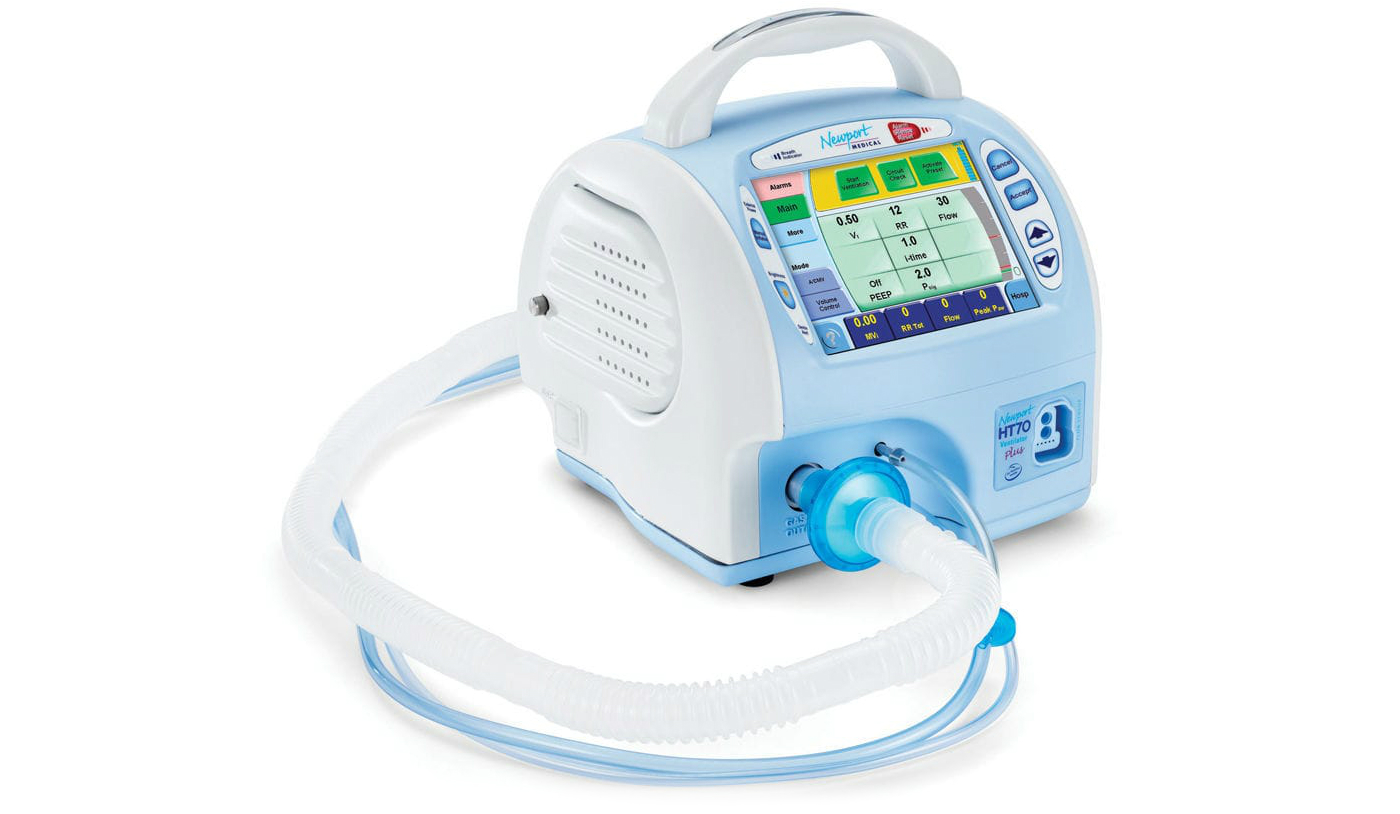
Расположенный в ручке аппарата световой индикатор виден со всех сторон.
Преимущества аппарата ИВЛ Newport HT70
При лечении хронических больных
- Удобен в настройке и использовании
- Мобильный, имеет небольшие размеры
- Совместим с системами центрального мониторинга и дистанционного оповещения
- Датчик концентрации кислорода, сигналы тревоги
- Использование кислорода высокого или низкого давления
 При использовании в лечебном учреждении
 При использовании в лечебном учреждении
- Графики кривых объема, потока и давления
- Датчик потока в дыхательных путях при инвазивной либо неинвазивной ИВЛ
- Пользовательские предустановки параметров пациента
- Журнал событий
При транспортировке
- Экономия электроэнергии и кислорода
- Расчет времени использования баллона O2
- Датчик концентрации кислорода с сигналом тревоги
- Оценка времени работы от аккумулятора
- Подходит для использования в санавиации и в салоне пассажирского самолета
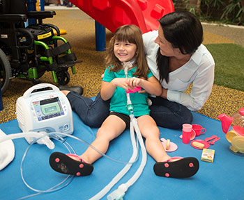
При медицинской помощи на дому
- Интуитивное управление, цветной сенсорный экран
- Отображение на экране справочной информации
- Возможность «горячей замены» аккумулятора без прерывания работы
При использовании в экстренных ситуациях
- Быстрая подготовка к работе благодаря наличию предустановок
- Прочная конструкция
- Быстрая настройка сигналов тревоги
- До 10 ч работы от встроенного полностью заряженного аккумулятора при стандартных настройках
Автономная работа
Аппарат ИВЛ Newport HT70 Plus не требует внешнего источника подачи сжатого газа. Нашими инженерами был разработан запатентованный микропоршневой компрессор, который работает тихо, не нагревается и экономит электроэнергию. Наши высокие производственные стандарты обеспечивают надежность и износоустойчивость на протяжении всего срока эксплуатации изделия.
Встроенная двойная аккумуляторная батарея аппарата ИВЛ Newport HT70 Plus изготовлена с использованием современной литий-ионной технологии и включает основной аккумулятор с возможностью «горячей замены», который обеспечивает до 10 ч работы,* а также резервный аккумулятор, который обеспечивает работу аппарата ИВЛ на протяжении как минимум 30 минут. Нужна более длительная работа? Просто замените аккумулятор Power Pac заряженным, не прерывая работу аппарата. Для замены не требуются какие-либо инструменты. Оба аккумулятора полностью заряжаются в течение трех часов.
При длительной транспортировке или прогулках, а также в случае прекращения подачи электроэнергии аппарат ИВЛ Newport HT70 Plus обеспечивает абсолютную безопасность пациента и душевное спокойствие ухаживающих за ним лиц.
Комплектация
| Транспортный аппарат ИВЛ в стандатной комплектации | 1 шт |
| Инструкция пользователя | 1 шт |
| Одноразовый контур пациента | 1 шт |
| Упаковка с принадлежностями | 1 шт |
| Cетевой кабель | 1 шт |
Технические характеристики
- Диапазон пациентов: дети более 5 кг, взрослые
- Режимы (давление или объем): А/CMV, SIMV, SPONT
- NIV (неинвазивная вентиляция): Вкл./выключение во всех режимах
- VT (дыхательный объем): от 50 до 2200 мл
- ЧД (частота дыхания) : от 1 до 99 уд/мин
- Время вдоха: от0,1 до 3,0 сек
- PEEP/CPAP: от 0 до 30 см Н2О
- PS (поддержка давлением): от 0 до 60 смН2О
- P тригер (чувствительность): -9,9 до 0 смН2О
- О2 (кислород): 21 до 100%
- Габариты: 24,74 см х 26,04 см х 27,94 см (ШхВхГ включая рукоятку)
- Вес: 6,9 кг
- Сенсорный экран: 13,2 х 9,9 см, диагональ 7 дюймов (17,78 см)
Получить КП, документацию, ДС/РУ и другую информацию вы можете отправив запрос на почту info@medpribor.pro
Производитель
Производитель
| Производитель / Бренд |
Covidien, Medtronic |
|---|---|
| Страна производства |
Ирландия |
| Гарантия |
24 месяца |
| Автономная работа |
Да |
| Тип ИВЛ |
Автономный ИВЛ, Детский ИВЛ, Инвазивный ИВЛ, Неинвазивный ИВЛ, Транспортный ИВЛ |
| Класс аппарата |
Средний, Профессиональный |
Отзывы (0)
Доставка
СПОСОБЫ ДОСТАВКИ:
- экспресс доставка в течении 5 часов собственным транспортом компании (Москва и область)
- курьерской службой или ТК по РФ и торговому союзу (до двери)
- до пунктов самовывоза
СПОСОБЫ ОПЛАТЫ: при получении или предоплата по счету
БЕСПЛАТНАЯ И ПЛАТНАЯ ДОСТАВКА:
- Бесплатная доставка медицинского оборудования при заказе от 10.000 рублей осуществляется по Москве и МО
- Бесплатная доставка медицинского оборудования при заказе от 60.000 рублей осуществляется по всей России
- Платная доставка заказов до 60.000 руб. осуществляется по всей России *
- Отправка заказов любой стоимостью в страны торгового союза осуществляется платно (в Казахстан, Беларусь и другие страны).
* Стоимость доставки до 60000 руб. рассчитывается в соответсвии с тарифами служб доставки (см. раздел доставки). Стоимость доставки зависит от габаритов товара и веса, подробный расчет вы можете получить у менеджеров интернет-магазина.
ДЛЯ КОНТРАКТНЫХ КЛИЕНТОВ: Мы осуществляем поставки медицинского оборудования оптом, в розницу и на тендерной основе. Для больниц, поликлиник, фондов и других организаций доставка, монтаж и обучение может быть включено в стоимость товара. (по желанию заказчика)
Файлы (3)
Возможно Вас также заинтересует…
Похожие товары
Компактный и легкий, аппарат ИВЛ HT70 предназначен для работы с большой нагрузкой, поскольку имеет износостойкую наружную поверхность из полимера и прочную общую конструкцию, способную обеспечить функционирование в жестких условиях.
Отличительное свойство аппарата ИВЛ HT70 — простота применения, все основные средства управления помещаются буквально на кончиках пальцев пользователя, поскольку управляется он простыми комбинациями нажатий мембранных кнопок и сенсорного экрана.
В аппарате нет трудных для восприятия меню или сложной последовательности действий, которым необходимо следовать, чтобы внести нужные корректировки в постоянно выполняемые операции.
Трехуровневая система профилей управления упрощает задачи персонала, ухаживающего за тяжелобольными, позволяя управлять всеми функциями устройства, одновременно обеспечивая быстрый доступ к наиболее значимым элементам в условиях транспортировки и существенно повышая безопасность и простоту при уходе за больными на дому.
Усовершенствованные клинические возможности
Помимо износостойкости и простоты применения, аппарат ИВЛ HT70 предоставляет полный комплект клинических возможностей, необходимых для оказания помощи тяжелобольным.
Способность двойного микропоршневого насоса подавать изменяющийся поток газа позволяет аппарату HT70 обеспечивать весь диапазон рабочих режимов и типов вентиляции, при которых ПДКВ контролируется сервоприводом с компенсированием утечек. Компенсация утечек помогает улучшить показатели срабатывания триггеров и избежать автозацикливания при утечке. Аппарат HT70 можно применять с эндотрахеальной трубкой, трахеальной трубкой, лицевой маской, назальной маской или канюлями, или с загубником.
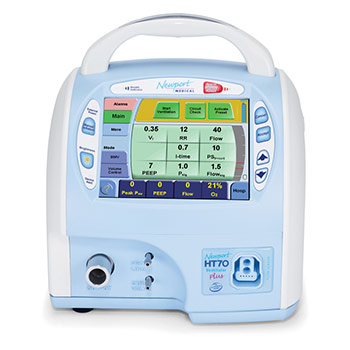
К аппаратам ИВЛ серии HT70 относятся три модели:
- HT70S HT70 Basic используется, когда поддержка по давлению не нужна.
- HT70 HT70 Classic, добавляется функция поддержки по давлению и связанные с ней параметры, а также окно «Тренды».
- HT70PM HT70 Plus, добавляется опция датчика потока воздуховода с выводом графиков, триггером потока и определением объемов выдоха.
Модели HT70 Basic и Classic обеспечивают контроль дыхательного объема вдоха (для каждого дыхательного цикла), минутного объема вдоха, общей частоты дыхания, пикового, среднего и базового (ПДКВ) давления. Давление в контуре пациента в реальном времени постоянно отображается на датчике давления воздуховода на передней панели. Комплексная система тревожного оповещения встроена в аппарат, чтобы предупреждать пользователя о нарушениях безопасных пределов, заданных пользователем или аппаратом ИВЛ. Дополнительный встроенный датчик кислорода позволяет контролировать O2 с установкой верхнего и нижнего пределов тревоги для O2.
В модели HT70 Plus добавляется датчик потока воздуховода с отображением экранных графиков, контроль/тревога по дыхательному и минутному объему выдоха и триггер потока. В этом руководстве описана модель HT70 Plus и указаны функции, не доступные в моделях HT70 и HT70S. Подаваемую пациенту дыхательную смесь можно обогатить кислородом (0,21–1,00) с помощью дополнительного воздушно-кислородного смесителя (50 psi) или дополнительного резервуара с низким потоком кислорода.
Исключительная мобильность
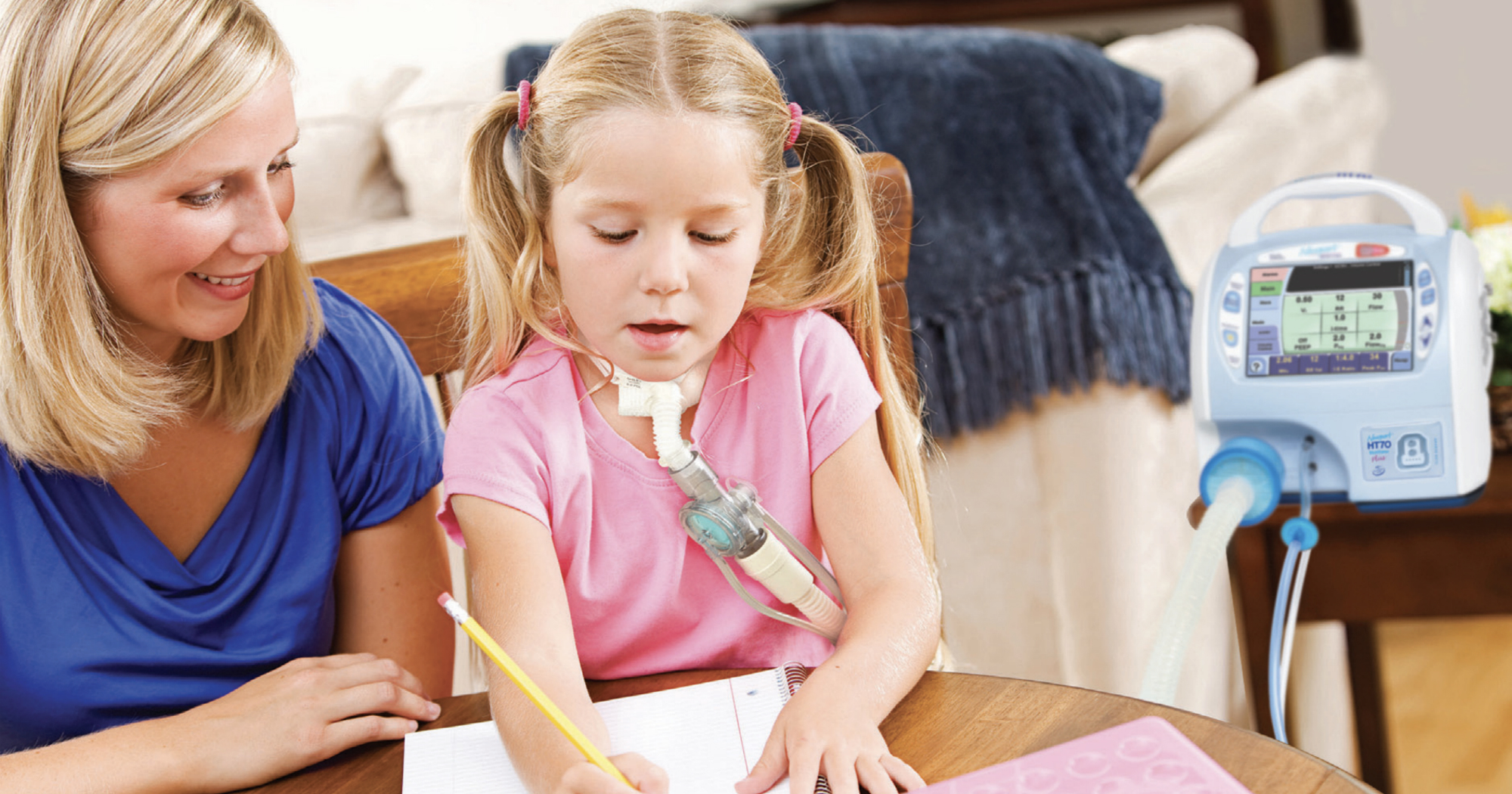
Уникальный дизайн аппарата ИВЛ обеспечивает его максимальную мобильность и безопасность для перевозки тяжелобольных на короткие и дальние расстояния, а также для пациентов, занимающихся обычными делами в своей повседневной жизни. Такая исключительная мобильность обеспечивается за счет двух источников: запатентованной компанией Newport энергосберегающей двойной микропоршневой технологии, которая устраняет необходимость наличия внешнего источника сжатой дыхательной смеси, и внутренней двойной системы батарей, которая обеспечивает практически непрерывную эксплуатацию аппарата на питании от батареи, основанную на технологии «горячей» замены.
Микропоршни аппарата HT70 используют лишь часть той мощности, которая потребляется турбинами и компрессорами. Это увеличивает время использования батареи. Кроме того, наша запатентованная система использует значительно меньше дополнительного кислорода, чем системы, оснащенные турбинами или компрессорами, что тоже повышает мобильность при перевозке или применении в уходе на дому.
Превосходство технологии нашей микропоршневой системы над системами, оснащенными турбинами или компрессорами, позволяет аппарату HT70 безопасно проводить вентиляцию при разнообразных внешних условиях и в широком диапазоне высот. Встроенный двойной микропоршневой насос аппарата HT70 состоит из механически подвижных деталей. Как и другие системы подачи дыхательной смеси с подвижными деталями, во время работы он может издавать небольшой шум. Это не является неисправностью и не влияет на работу аппарата ИВЛ.
Внутренняя двойная система батарей состоит из двух независимых друг от друга, но скоординированных в работе ионно-литиевых батарей: батареи Power Pac, которая расположена позади аппарата ИВЛ, и внутренней батареи, размещенной в самом аппарате. Внутренняя двойная система батарей, если она новая и полностью заряжена, способна обеспечить до 10 часов работы аппарата ИВЛ со стандартными настройками. Такая система гарантирует непрерывную поддержку при транспортировке, в повседневной деятельности и при нарушении энергоснабжения.
Съемная батарея Power Pac подходит для «горячей» замены. Это означает, что если требуется продлить питание от батареи, разряженную батарею Power Pac можно легко вынуть из аппарата HT70 и заменить заряженной батареей Power Pac, не прерывая вентиляции. Для этого не нужны инструменты. Дополнительная внутренняя батарея резервного питания поддерживает непрерывность работы во время замены батареи Power Pac и способна обеспечить не менее 30 минут работы при полной загрузке, когда все другие источники питания истощены. Вес батареи Power Pac составляет два фунта (0,9 кг); она заряжается при каждом подключении аппарата ИВЛ к внешнему источнику питания (переменного или постоянного тока).
Помимо этого ее можно заряжать отдельно. Аппарат HT70 может работать от внешних источников питания с различными параметрами переменного (100–240 В переменного тока при 50/60 Гц) или постоянного тока (12–24 В постоянного тока) или от внутренней двойной системы батарей. Дополнительный адаптер для питания от автомобильной розетки прикуривателя (постоянного тока) позволяет подключаться к автомобильной розетке постоянного тока. Обе батареи внутренней двойной системы батарей заряжаются при каждом подключении аппарата ИВЛ к внешнему источнику питания, независимо от того, используется аппарат в этот момент или нет.
- Диапазон пациентов: дети более 5 кг, взрослые
- Режимы (давление или объем): А/CMV, SIMV, SPONT
- NIV (неинвазивная вентиляция): Вкл./выключение во всех режимах
- VT (дыхательный объем): от 50 до 2200 мл
- ЧД (частота дыхания) : от 1 до 99 уд/мин
- Время вдоха: от0,1 до 3,0 сек
- PEEP/CPAP: от 0 до 30 см Н2О
- PS (поддержка давлением): от 0 до 60 смН2О
- P тригер (чувствительность): -9,9 до 0 смН2О
- О2 (кислород): 21 до 100%
Особенности модели
- Мобильный, легкий и прочный;
- Сенсорный, интуитивно понятный и цветной дисплей;
- Информативный графический мониторинг с графиками кривых;
- Датчик потока и датчик концентрации кислорода;
- Возможность включения пользовательских предустановок и настроек одной кнопкой;
- Гибкий и понятный в настройке под индивидуальные требования;
- Журнал событий;
- Цветные настраиваемые тревожные оповещения;
- Литий-ионный аккумулятор с возможностью замены без остановки работы аппарата;
- Полная зарядка аккумулятора за 3 часа;
- Калькулятор использования баллона;
- Оценка использования аккумулятора;
- Энергоёмкий износоустойчивый компрессор;
- Триггер по потоку и триггер по давлению;
- Справочная информация по одному нажатию;
- 3 готовых профиля и 11 режимов работы;
- Подходит не только для взрослых пользователей, но и для детей, весом более 5 кг.
Причины, по которым Newport HT70 Plus выгодно купить именно у нас:
- Мы предлагаем гарантийное, постгарантийное и сервисное обслуживание приобретенных у нас аппаратов.
- Каждый аппарат Newport HT70 Plus проходит проверку на работоспособность, что минимализирует вероятность брака.
- Осуществляем самую быструю и бесплатную доставку в любую точку России.
- Покупая аппарат у нашей компании, Вы избавляетесь от риска приобрести некачественный товар.
Назначение аппарата ИВЛ Newport HT 70 заключено в обеспечении непрерывной и периодической искусственной вентиляции легких с положительным давлением. Newport HT70 идеально подходит для ухода за лицами, нуждающимися в механической вентиляции посредством инвазивных или неинвазивных интерфейсов.
Данная модель подходит не только для взрослых пациентов, но и для младенцев и детей весом от 5 кг. NewPort HT 70 широко применяется для оказания медицинской помощи как на дому, так и для эксплуатации в больничных условиях, в том числе, для оказания помощи тяжело больным пациентам, требующим длительного ухода. Также аппарат незаменим при транспортировке пациентов и экстренной вентиляции.
NewPort HT 70 отличают легкость, высокая мобильность, прочность конструкции и надежность. Аппарат легко настраивается благодаря цветному и яркому сенсорному дисплею соответственно потребностям, как медперсоналом для пациента, так и самим пользователем в домашних условиях. Для этого у данной модели есть несколько профилей использования: «Дом», «Транспорт» и «Клиника». Именно профиль «Клиника» открывает полный доступ к настройкам и функционалу. Профиль для дома имеет упрощенный интерфейс, а профиль «Транспорт» дает доступ к необходимым параметрам тревожных оповещений и мониторинга состояния в поездках. Учтена возможность и тонкой настройки под конкретные требования ухода – готовые наборы предустановок, которые активируются всего одной кнопкой.

Вентилятор HT 70 также обладает функцией датчика потока воздуха в дыхательных путях с возможностью включения сигналов тревоги, что обеспечивает высокую чувствительность аппарата к состоянию пациента, расширяет возможности мониторинга и обеспечивает наибольшую эффективность лечения и ухода. Индикаторы оповещений имеют цветовые различия и легко распознаваемы.
Использование этого мобильного вентилятора максимально комфортно за счет точной синхронизации с пользователем в режиме реального времени при использовании поддержки давлением. Имеется и контроль утечек при применении безманжеточной эндотрахеальной трубки или неинвазивной вентиляции, а автоматическая компенсация утечек помогает устранить автозацикливание.

Калькулятор использования кислородного баллона и оценка заряда батареи делают NewPort HT 70 практичнее аналогов. Двойная аккумуляторная батарея обеспечивает до 10 часов непрерывной работы, а резервный аккумулятор до 30 дополнительных минут. Предусмотрена замена батареи на заряженную без инструментов и без прерывания работы, что незаменимо при длительной транспортировке пациента или сбоях в подаче электроэнергии.
Всю информацию о текущих настройках, мониторинге и режимах можно просмотреть в одно нажатие. Устройство не требует внешнего источника сжатого газа, так как в него встроен износостойкий компрессор, работающий почти бесшумно.
Основные преимущества:
- Мобильный, легкий и прочный;
- Сенсорный, интуитивно понятный цветной дисплей;
- Информативный графический мониторинг;
- Датчик потока и датчик концентрации кислорода;
- Возможность включения пользовательских настроек одной кнопкой;
- Гибкий и понятный в настройке под индивидуальные требования;
- Журнал событий;
- Настраиваемые тревожные оповещения;
- Литий-ионный аккумулятор с возможностью замены без остановки работы аппарата;
- Автономная работа до 10 часов, резервный аккумулятор на дополнительные 30 минут;
- Полная зарядка аккумулятора за 3 часа;
- Калькулятор использования баллона;
- Оценка остатка заряда аккумулятора;
- Энергоемкий износоустойчивый компрессор;
- Триггер по потоку и по давлению;
- Справочная информация в одно нажатие;
- 3 готовых профиля и 11 режимов работы;
- Походит не только для взрослых пользователей, но и для детей, весом более 5 кг.
Характеристики
|
Максимальная концентрация кислорода |
21 до 100% |
|
Режим работы |
А/CMV, SIMV, SPONT (NIV (неинвазивная вентиляция) вкл./выключение во всех режимах) |
|
Размеры |
24,74 см х 26,04 см х 27,94 см (включая рукоятку) |
|
Вес |
6,9 кг |
|
Дисплей |
цветной, сенсорный, 7” |
|
Категория пациентов |
дети более 5 кг, взрослые |
|
Автономная работа |
Работа аккумулятора: до 10 часов / Работа резервного аккумулятора: 30 минут |
|
Время вдоха |
от 0,1 до 3,0 сек |
|
Частота дыхания |
от 1 до 99 уд/мин |
|
Уровень PEEP/CPAP |
от 0 до 30 см Н2О |
|
Дыхательный объем |
от 50 до 2200 мл |
|
Давление |
от 0 до 60 см Н2О |
|
Чувствительность |
-9,9 до 0 см Н2О |
|
Страна производства |
США |
|
Тип |
аппарат ИВЛ |
|
Комплектация |
Транспортный аппарат ИВЛ Newport HT 70 – 1 шт., Инструкция пользователя – 1 шт., Одноразовый контур пациента – 1 шт., Упаковка с принадлежностями – 1 шт., Cетевой кабель – 1 шт. |