 Loading…
![]()
HD3
Service Manual
4535 612 34161 Rev A August 2005
CSIP Level 1
Copyright © 2005 Koninklijke Philips Electronics N.V. All rights reserved
About This Manual
Audience |
This document and the information contained in it is strictly reserved for current Philips Medical |
|
Systems (“Philips”) personnel, Philips licensed representatives, and Philips customers who have |
|
|
purchased a valid service agreement for use by the customer’s designated in-house service |
|
|
employee on equipment located at the customer’s designated site. Use of this document by |
|
|
unauthorized persons is strictly prohibited. This document must be returned to Philips when the |
|
|
user is no longer licensed and in any event upon Philips’ first written request. |
|
|
This manual supports the field service maintenance and repair of the HD3 Ultrasound System. |
|
|
The user of this document is a qualified ultrasound electronics technician who has completed |
|
|
training classes on the system and its peripherals. |
|
Manual Format |
This manual is in Portable Document Format (PDF), for viewing on a laptop computer with |
|
Acrobat Reader. A list of bookmarks functions as an additional table of contents. Those book- |
|
|
marks, the table of contents, and cross-references use hypertext links to provide access to the |
|
|
referenced information. |
Conventions
in This Manual
The following conventions are used in this manual:
•Hypertext links are blue.
•All procedures are numbered, and all subprocedures are lettered. You must complete steps in the sequence they are presented to ensure reliable results.
|
4535 612 34161 HD3 Service Manual |
Page 2 |
|
CSIP Level 1 |
About This Manual |
Service Manual Questions
or Comments
•Bulleted lists indicate general information about a function or procedure. They do not imply a sequential procedure.
•Control names and menu items or titles are spelled as they are on the system, and they appear in bold text.
•Symbols appear as they appear on the system.
•An English system is assumed.
If you have questions about the service manual, or you discover an error in the manual, contact Philips Ultrasound Technical Communications:
•bothell.techpubs@philips.com
•Technical Communications, MS 964, at the address below
|
Customer |
Various support locations around the world can provide customers technical assistance with the |
|
Assistance |
ultrasound system. Customers should contact the representative or sales office from which they |
|
purchased the system or the nearest Philips Ultrasound office. |
Philips Ultrasound
22100 Bothell-Everett Highway Bothell, WA 98021-8431
USA
425-487-7000 or 800-426-2670 www.medical.philips.com
|
4535 612 34161 HD3 Service Manual |
Page 3 |
|
CSIP Level 1 |
About This Manual |
“HD3”, “Chroma” and “Color Power Angio” are trademarks of Koninklijke Philips Electronics N.V.
Non-Philips product names may be trademarks or registered trademarks of their respective owners.
This document and the information contained in it is proprietary and confidential information of Philips Medical Systems (“Philips”) and may not be reproduced, copied in whole or in part, adapted, modified, disclosed to others, or disseminated without the prior written permission of the Philips Legal Department. Use of this document and the information contained in it is strictly reserved for current Philips personnel and Philips customers who have a current and valid license from Philips for use by the customer’s designated in-house service employee on equipment located at the customer’s designated site. Use of this document by unauthorized persons is strictly prohibited. Report violation of these requirements to the Philips Legal Department. This document must be returned to Philips when the user is no longer licensed and in any event upon Philips’ first written request.
Philips provides this document without warranty of any kind, implied or expressed, including, but not limited to, the implied warranties of merchantability and fitness for a particular purpose.
Philips has taken care to ensure the accuracy of this document. However, Philips assumes no liability for errors or omissions and reserves the right to make changes without further notice to any products herein to improve reliability, function, or design. Philips may make improvements or changes in the products or programs described in this document at any time.
|
4535 612 34161 HD3 Service Manual |
Page 4 |
|
CSIP Level 1 |
Contents |
Contents
About This Manual . . . . . . . . . . . . . . . . . . . . . . . . . . . . . . . . . . . . . . . . . . . . . . . . . . . . . . . . . . . . . . . . . . . . . . . .1
Audience . . . . . . . . . . . . . . . . . . . . . . . . . . . . . . . . . . . . . . . . . . . . . . . . . . . . . . . . . . . . . . . . . . . . . . . . . . . . . . . . . . . . . . . 1 Manual Format . . . . . . . . . . . . . . . . . . . . . . . . . . . . . . . . . . . . . . . . . . . . . . . . . . . . . . . . . . . . . . . . . . . . . . . . . . . . . . . . . . 1 Conventions in This Manual . . . . . . . . . . . . . . . . . . . . . . . . . . . . . . . . . . . . . . . . . . . . . . . . . . . . . . . . . . . . . . . . . . . . . . . . 1 Service Manual Questions or Comments . . . . . . . . . . . . . . . . . . . . . . . . . . . . . . . . . . . . . . . . . . . . . . . . . . . . . . . . . . . . . 2 Customer Assistance . . . . . . . . . . . . . . . . . . . . . . . . . . . . . . . . . . . . . . . . . . . . . . . . . . . . . . . . . . . . . . . . . . . . . . . . . . . . . 2
|
General Information . . . . . . . . . . . . . . . . . . . . . . . . . . . . . . . . . . . . . . . . . . . . . . . . . . . . . . . . . . . . . . . . . . . . . . |
25 |
|
Introduction . . . . . . . . . . . . . . . . . . . . . . . . . . . . . . . . . . . . . . . . . . . . . . . . . . . . . . . . . . . . . . . . . . . . . . . . . . . . . . . . . . . . . . |
25 |
|
More About This Manual . . . . . . . . . . . . . . . . . . . . . . . . . . . . . . . . . . . . . . . . . . . . . . . . . . . . . . . . . . . . . . . . . . . . . . . . . . . . |
25 |
|
System Overview . . . . . . . . . . . . . . . . . . . . . . . . . . . . . . . . . . . . . . . . . . . . . . . . . . . . . . . . . . . . . . . . . . . . . . . . . . . . . . . . . . |
27 |
|
Figure 1-1 HD3 Ultrasound System . . . . . . . . . . . . . . . . . . . . . . . . . . . . . . . . . . . . . . . . . . . . . . . . . . . . . . . . . . . . . . |
28 |
|
Applications . . . . . . . . . . . . . . . . . . . . . . . . . . . . . . . . . . . . . . . . . . . . . . . . . . . . . . . . . . . . . . . . . . . . . . . . . . . . . . . . . . . |
29 |
|
Modes . . . . . . . . . . . . . . . . . . . . . . . . . . . . . . . . . . . . . . . . . . . . . . . . . . . . . . . . . . . . . . . . . . . . . . . . . . . . . . . . . . . . . . . . |
29 |
|
Transducers . . . . . . . . . . . . . . . . . . . . . . . . . . . . . . . . . . . . . . . . . . . . . . . . . . . . . . . . . . . . . . . . . . . . . . . . . . . . . . . . . . . |
30 |
|
Languages . . . . . . . . . . . . . . . . . . . . . . . . . . . . . . . . . . . . . . . . . . . . . . . . . . . . . . . . . . . . . . . . . . . . . . . . . . . . . . . . . . . . . |
30 |
|
Options . . . . . . . . . . . . . . . . . . . . . . . . . . . . . . . . . . . . . . . . . . . . . . . . . . . . . . . . . . . . . . . . . . . . . . . . . . . . . . . . . . . . . . . |
31 |
|
Peripherals . . . . . . . . . . . . . . . . . . . . . . . . . . . . . . . . . . . . . . . . . . . . . . . . . . . . . . . . . . . . . . . . . . . . . . . . . . . . . . . . . . . . |
32 |
|
Figure 1-2 HD3 Ultrasound System Image Printers and VCR . . . . . . . . . . . . . . . . . . . . . . . . . . . . . . . . . . . . . . . . . |
33 |
|
Figure 1-3 HD3 Ultrasound System Data Media . . . . . . . . . . . . . . . . . . . . . . . . . . . . . . . . . . . . . . . . . . . . . . . . . . . . |
34 |

|
4535 612 34161 HD3 Service Manual |
Page 5 |
|
CSIP Level 1 |
Contents |
|
Figure 1-4 HD3 Ultrasound System Foot Switch . . . . . . . . . . . . . . . . . . . . . . . . . . . . . . . . . . . . . . . . . . . . . |
. . . . . . 35 |
|
Physical Description . . . . . . . . . . . . . . . . . . . . . . . . . . . . . . . . . . . . . . . . . . . . . . . . . . . . . . . . . . . . . . . . . . . . . . . . . . |
. . . . . . 36 |
|
Cart . . . . . . . . . . . . . . . . . . . . . . . . . . . . . . . . . . . . . . . . . . . . . . . . . . . . . . . . . . . . . . . . . . . . . . . . . . . . . . . . . . . . |
. . . . . . 36 |
|
System Control Panel . . . . . . . . . . . . . . . . . . . . . . . . . . . . . . . . . . . . . . . . . . . . . . . . . . . . . . . . . . . . . . . . . . . . . . |
. . . . . . 36 |
|
Figure 1-5 HD3 Ultrasound System Control Panel . . . . . . . . . . . . . . . . . . . . . . . . . . . . . . . . . . . . . . . . . . . . |
. . . . . . 37 |
|
System Monitor . . . . . . . . . . . . . . . . . . . . . . . . . . . . . . . . . . . . . . . . . . . . . . . . . . . . . . . . . . . . . . . . . . . . . . . . . . |
. . . . . . 37 |
|
Ultrasound Components . . . . . . . . . . . . . . . . . . . . . . . . . . . . . . . . . . . . . . . . . . . . . . . . . . . . . . . . . . . . . . . . . . . |
. . . . . . 37 |
|
System Power Components . . . . . . . . . . . . . . . . . . . . . . . . . . . . . . . . . . . . . . . . . . . . . . . . . . . . . . . . . . . . . . . . . |
. . . . . . 38 |
|
Software and Data Storage Components . . . . . . . . . . . . . . . . . . . . . . . . . . . . . . . . . . . . . . . . . . . . . . . . . . . . . . |
. . . . . . 38 |
|
I/O Panel . . . . . . . . . . . . . . . . . . . . . . . . . . . . . . . . . . . . . . . . . . . . . . . . . . . . . . . . . . . . . . . . . . . . . . . . . . . . . . . . |
. . . . . . 39 |
|
Cables . . . . . . . . . . . . . . . . . . . . . . . . . . . . . . . . . . . . . . . . . . . . . . . . . . . . . . . . . . . . . . . . . . . . . . . . . . . . . . . . . . |
. . . . . . 39 |
|
Device Safety Requirements and Regulatory Compliance . . . . . . . . . . . . . . . . . . . . . . . . . . . . . . . . . . . . . . . . . . . . |
. . . . . . 39 |
|
Supplies and Accessories . . . . . . . . . . . . . . . . . . . . . . . . . . . . . . . . . . . . . . . . . . . . . . . . . . . . . . . . . . . . . . . . . . . . . . |
. . . . . . 40 |
|
Open Source Software License . . . . . . . . . . . . . . . . . . . . . . . . . . . . . . . . . . . . . . . . . . . . . . . . . . . . . . . . . . . . . . . . . |
. . . . . . 40 |
|
System Specifications . . . . . . . . . . . . . . . . . . . . . . . . . . . . . . . . . . . . . . . . . . . . . . . . . . . . . . . . . . . . . . . |
. . . . . .41 |
|
Introduction . . . . . . . . . . . . . . . . . . . . . . . . . . . . . . . . . . . . . . . . . . . . . . . . . . . . . . . . . . . . . . . . . . . . . . . . . . . . . . . . |
. . . . . . 41 |
|
Physical Specifications . . . . . . . . . . . . . . . . . . . . . . . . . . . . . . . . . . . . . . . . . . . . . . . . . . . . . . . . . . . . . . . . . . . . . . . . . |
. . . . . . 41 |
|
Electrical Specifications . . . . . . . . . . . . . . . . . . . . . . . . . . . . . . . . . . . . . . . . . . . . . . . . . . . . . . . . . . . . . . . . . . . . . . . . |
. . . . . . 41 |
|
Environmental Specifications . . . . . . . . . . . . . . . . . . . . . . . . . . . . . . . . . . . . . . . . . . . . . . . . . . . . . . . . . . . . . . . . . . . |
. . . . . . 42 |
|
System PC Specifications . . . . . . . . . . . . . . . . . . . . . . . . . . . . . . . . . . . . . . . . . . . . . . . . . . . . . . . . . . . . . . . . . . . . . . |
. . . . . . 42 |
|
Table 2-1 Embedded PC Hardware Specifications . . . . . . . . . . . . . . . . . . . . . . . . . . . . . . . . . . . . . . . . . . . . |
. . . . . . 42 |

|
4535 612 34161 HD3 Service Manual |
Page 6 |
|
CSIP Level 1 |
Contents |
|
Monitor Specifications . . . . . . . . . . . . . . . . . . . . . . . . . . . . . . . . . . . . . . . . . . . . . . . . . . . . . . . . . . . . . . . . . . . . . . . . |
. . . . . . 43 |
|
Image Formats . . . . . . . . . . . . . . . . . . . . . . . . . . . . . . . . . . . . . . . . . . . . . . . . . . . . . . . . . . . . . . . . . . . . . . . . . . . . . . |
. . . . . . 44 |
|
Table 2-2 Supported Image Formats . . . . . . . . . . . . . . . . . . . . . . . . . . . . . . . . . . . . . . . . . . . . . . . . . . . . . . . |
. . . . . . 44 |
|
Safety . . . . . . . . . . . . . . . . . . . . . . . . . . . . . . . . . . . . . . . . . . . . . . . . . . . . . . . . . . . . . . . . . . . . . . . . . . . . |
. . . . . .45 |
|
Introduction . . . . . . . . . . . . . . . . . . . . . . . . . . . . . . . . . . . . . . . . . . . . . . . . . . . . . . . . . . . . . . . . . . . . . . . . . . . . . . . . |
. . . . . . 45 |
|
About Safety Information . . . . . . . . . . . . . . . . . . . . . . . . . . . . . . . . . . . . . . . . . . . . . . . . . . . . . . . . . . . . . . . . . . . . . . |
. . . . . . 45 |
|
General Operating Safety . . . . . . . . . . . . . . . . . . . . . . . . . . . . . . . . . . . . . . . . . . . . . . . . . . . . . . . . . . . . . . . . . . . . . . |
. . . . . . 45 |
|
Electrical Safety . . . . . . . . . . . . . . . . . . . . . . . . . . . . . . . . . . . . . . . . . . . . . . . . . . . . . . . . . . . . . . . . . . . . . . . . . . . . . . |
. . . . . . 46 |
|
Avoiding EMI and RF . . . . . . . . . . . . . . . . . . . . . . . . . . . . . . . . . . . . . . . . . . . . . . . . . . . . . . . . . . . . . . . . . . . . . . |
. . . . . . 48 |
|
Mechanical Safety . . . . . . . . . . . . . . . . . . . . . . . . . . . . . . . . . . . . . . . . . . . . . . . . . . . . . . . . . . . . . . . . . . . . . . . . . . . . |
. . . . . . 49 |
|
General Equipment Protection . . . . . . . . . . . . . . . . . . . . . . . . . . . . . . . . . . . . . . . . . . . . . . . . . . . . . . . . . . . . . . . . . |
. . . . . . 50 |
|
About Electrostatic Discharge . . . . . . . . . . . . . . . . . . . . . . . . . . . . . . . . . . . . . . . . . . . . . . . . . . . . . . . . . . . . . . . |
. . . . . . 51 |
|
Symbols . . . . . . . . . . . . . . . . . . . . . . . . . . . . . . . . . . . . . . . . . . . . . . . . . . . . . . . . . . . . . . . . . . . . . . . . . . . . . . . . . . . . |
. . . . . . 52 |
|
Theory of Operation . . . . . . . . . . . . . . . . . . . . . . . . . . . . . . . . . . . . . . . . . . . . . . . . . . . . . . . . . . . . . . . . |
. . . . . .58 |
|
Introduction . . . . . . . . . . . . . . . . . . . . . . . . . . . . . . . . . . . . . . . . . . . . . . . . . . . . . . . . . . . . . . . . . . . . . . . . . . . . . . . . |
. . . . . . 58 |
|
System Architecture . . . . . . . . . . . . . . . . . . . . . . . . . . . . . . . . . . . . . . . . . . . . . . . . . . . . . . . . . . . . . . . . . . . . . . . . . . |
. . . . . . 58 |
|
Operating System . . . . . . . . . . . . . . . . . . . . . . . . . . . . . . . . . . . . . . . . . . . . . . . . . . . . . . . . . . . . . . . . . . . . . . . . . . . . |
. . . . . . 58 |
|
Functional Description . . . . . . . . . . . . . . . . . . . . . . . . . . . . . . . . . . . . . . . . . . . . . . . . . . . . . . . . . . . . . . . . . . . . . . . . |
. . . . . . 59 |
|
Figure 4-1 HD3 System Functional Block Diagram . . . . . . . . . . . . . . . . . . . . . . . . . . . . . . . . . . . . . . . . . . . . |
. . . . . . 60 |
|
Physical Functions . . . . . . . . . . . . . . . . . . . . . . . . . . . . . . . . . . . . . . . . . . . . . . . . . . . . . . . . . . . . . . . . . . . . . . . . . |
. . . . . . 61 |
|
System Power . . . . . . . . . . . . . . . . . . . . . . . . . . . . . . . . . . . . . . . . . . . . . . . . . . . . . . . . . . . . . . . . . . . . . . . . . . . . |
. . . . . . 61 |

|
4535 612 34161 HD3 Service Manual |
Page 7 |
|
CSIP Level 1 |
Contents |
|
Transducer Connector Assembly (TCA) . . . . . . . . . . . . . . . . . . . . . . . . . . . . . . . . . . . . . . . . . . . . . . . . . . . . . . |
. . . . . . 63 |
|
Front End (FE) Board . . . . . . . . . . . . . . . . . . . . . . . . . . . . . . . . . . . . . . . . . . . . . . . . . . . . . . . . . . . . . . . . . . . . . . |
. . . . . . 63 |
|
Beamformer (BF) . . . . . . . . . . . . . . . . . . . . . . . . . . . . . . . . . . . . . . . . . . . . . . . . . . . . . . . . . . . . . . . . . . . . . . . . . |
. . . . . . 63 |
|
Digital Scan Converter (DSC) . . . . . . . . . . . . . . . . . . . . . . . . . . . . . . . . . . . . . . . . . . . . . . . . . . . . . . . . . . . . . . . |
. . . . . . 63 |
|
PCC Board . . . . . . . . . . . . . . . . . . . . . . . . . . . . . . . . . . . . . . . . . . . . . . . . . . . . . . . . . . . . . . . . . . . . . . . . . . . . . . |
. . . . . . 64 |
|
E-box Backplane . . . . . . . . . . . . . . . . . . . . . . . . . . . . . . . . . . . . . . . . . . . . . . . . . . . . . . . . . . . . . . . . . . . . . . . . . . |
. . . . . . 65 |
|
Input/Output Panel . . . . . . . . . . . . . . . . . . . . . . . . . . . . . . . . . . . . . . . . . . . . . . . . . . . . . . . . . . . . . . . . . . . . . . . . |
. . . . . . 65 |
|
User Interface . . . . . . . . . . . . . . . . . . . . . . . . . . . . . . . . . . . . . . . . . . . . . . . . . . . . . . . . . . . . . . . . . . . . . . . . . . . . |
. . . . . . 65 |
|
Hard Disk Drive (HDD) . . . . . . . . . . . . . . . . . . . . . . . . . . . . . . . . . . . . . . . . . . . . . . . . . . . . . . . . . . . . . . . . . . . . |
. . . . . . 66 |
|
CD-RW . . . . . . . . . . . . . . . . . . . . . . . . . . . . . . . . . . . . . . . . . . . . . . . . . . . . . . . . . . . . . . . . . . . . . . . . . . . . . . . . . |
. . . . . . 66 |
|
Magneto-optical Disk (MOD) Drive . . . . . . . . . . . . . . . . . . . . . . . . . . . . . . . . . . . . . . . . . . . . . . . . . . . . . . . . . . |
. . . . . . 66 |
|
Flash Memory Stick . . . . . . . . . . . . . . . . . . . . . . . . . . . . . . . . . . . . . . . . . . . . . . . . . . . . . . . . . . . . . . . . . . . . . . . . |
. . . . . . 66 |
|
Installation . . . . . . . . . . . . . . . . . . . . . . . . . . . . . . . . . . . . . . . . . . . . . . . . . . . . . . . . . . . . . . . . . . . . . . . . |
. . . . . .67 |
|
Introduction . . . . . . . . . . . . . . . . . . . . . . . . . . . . . . . . . . . . . . . . . . . . . . . . . . . . . . . . . . . . . . . . . . . . . . . . . . . . . . . . |
. . . . . . 67 |
|
Installation Checklist . . . . . . . . . . . . . . . . . . . . . . . . . . . . . . . . . . . . . . . . . . . . . . . . . . . . . . . . . . . . . . . . . . . . . . . . . . |
. . . . . . 67 |
|
Inspecting the Installation Site . . . . . . . . . . . . . . . . . . . . . . . . . . . . . . . . . . . . . . . . . . . . . . . . . . . . . . . . . . . . . . . . . . |
. . . . . . 68 |
|
Checking Physical Access for Delivery and Installation . . . . . . . . . . . . . . . . . . . . . . . . . . . . . . . . . . . . . . . . . . . . |
. . . . . . 68 |
|
Checking Electrical and Environmental Requirements . . . . . . . . . . . . . . . . . . . . . . . . . . . . . . . . . . . . . . . . . . . . |
. . . . . . 69 |
|
Gathering Site Network (DICOM) Information . . . . . . . . . . . . . . . . . . . . . . . . . . . . . . . . . . . . . . . . . . . . . . . . |
. . . . . . 69 |
|
Uncrating and Unpacking the System . . . . . . . . . . . . . . . . . . . . . . . . . . . . . . . . . . . . . . . . . . . . . . . . . . . . . . . . . . . . . |
. . . . . . 70 |
|
Inspecting the Crate . . . . . . . . . . . . . . . . . . . . . . . . . . . . . . . . . . . . . . . . . . . . . . . . . . . . . . . . . . . . . . . . . . . . . . |
. . . . . . 70 |

|
4535 612 34161 HD3 Service Manual |
Page 8 |
|
CSIP Level 1 |
Contents |
|
Uncrating . . . . . . . . . . . . . . . . . . . . . . . . . . . . . . . . . . . . . . . . . . . . . . . . . . . . . . . . . . . . . . . . . . . . . . . . . . . . . . . |
. . . . . . 71 |
|
Inspecting the System . . . . . . . . . . . . . . . . . . . . . . . . . . . . . . . . . . . . . . . . . . . . . . . . . . . . . . . . . . . . . . . . . . . . . . . . . |
. . . . . . 71 |
|
To inspect the system after uncrating . . . . . . . . . . . . . . . . . . . . . . . . . . . . . . . . . . . . . . . . . . . . . . . . . . . . . . |
. . . . . . 71 |
|
Assembling the System . . . . . . . . . . . . . . . . . . . . . . . . . . . . . . . . . . . . . . . . . . . . . . . . . . . . . . . . . . . . . . . . . . . . . . . . |
. . . . . . 72 |
|
Installing the Printers, VCR, and Footswitch . . . . . . . . . . . . . . . . . . . . . . . . . . . . . . . . . . . . . . . . . . . . . . . . . . . . |
. . . . . . 72 |
|
Installing the System Power Cord . . . . . . . . . . . . . . . . . . . . . . . . . . . . . . . . . . . . . . . . . . . . . . . . . . . . . . . . . . . . |
. . . . . . 72 |
|
Powering On and Configuring the System . . . . . . . . . . . . . . . . . . . . . . . . . . . . . . . . . . . . . . . . . . . . . . . . . . . . . . . . . |
. . . . . . 72 |
|
Verifying the Local Settings . . . . . . . . . . . . . . . . . . . . . . . . . . . . . . . . . . . . . . . . . . . . . . . . . . . . . . . . . . . . . . . . . |
. . . . . . 73 |
|
To check or set the institution name . . . . . . . . . . . . . . . . . . . . . . . . . . . . . . . . . . . . . . . . . . . . . . . . . . . . . . |
. . . . . . 73 |
|
Figure 5-1 Setup Window (System) . . . . . . . . . . . . . . . . . . . . . . . . . . . . . . . . . . . . . . . . . . . . . . . . . . . . . . . . |
. . . . . . 74 |
|
To verify or set the system time and date . . . . . . . . . . . . . . . . . . . . . . . . . . . . . . . . . . . . . . . . . . . . . . . . . . . |
. . . . . . 75 |
|
To change the user interface language . . . . . . . . . . . . . . . . . . . . . . . . . . . . . . . . . . . . . . . . . . . . . . . . . . . . . . |
. . . . . . 75 |
|
Verifying the System Options . . . . . . . . . . . . . . . . . . . . . . . . . . . . . . . . . . . . . . . . . . . . . . . . . . . . . . . . . . . . . . . . |
. . . . . . 76 |
|
To verify or activate system software options . . . . . . . . . . . . . . . . . . . . . . . . . . . . . . . . . . . . . . . . . . . . . . . |
. . . . . . 76 |
|
Figure 5-2 Setup Window (Option) . . . . . . . . . . . . . . . . . . . . . . . . . . . . . . . . . . . . . . . . . . . . . . . . . . . . . . . |
. . . . . . 77 |
|
Configuring the DICOM Feature . . . . . . . . . . . . . . . . . . . . . . . . . . . . . . . . . . . . . . . . . . . . . . . . . . . . . . . . . . . . . |
. . . . . . 78 |
|
To configure the system DICOM parameters . . . . . . . . . . . . . . . . . . . . . . . . . . . . . . . . . . . . . . . . . . . . . . . . |
. . . . . . 78 |
|
Figure 5-3 Setup Window (DICOM) . . . . . . . . . . . . . . . . . . . . . . . . . . . . . . . . . . . . . . . . . . . . . . . . . . . . . . |
. . . . . . 79 |
|
To identify the DICOM storage devices that the system will use . . . . . . . . . . . . . . . . . . . . . . . . . . . . . . . . |
. . . . . . 80 |
|
To identify the DICOM printers that the system will use . . . . . . . . . . . . . . . . . . . . . . . . . . . . . . . . . . . . . . |
. . . . . . 80 |
|
Figure 5-4 System Network Settings Window (DICOM) . . . . . . . . . . . . . . . . . . . . . . . . . . . . . . . . . . . . . . |
. . . . . . 81 |

|
4535 612 34161 HD3 Service Manual |
Page 9 |
|
CSIP Level 1 |
Contents |
|
Figure 5-5 Server Configuration Window (DICOM) . . . . . . . . . . . . . . . . . . . . . . . . . . . . . . . . . . . . . . . . . |
. . . . . . 82 |
|
To test the communication between the system and a server or a printer . . . . . . . . . . . . . . . . . . . . . . . . |
. . . . . . 83 |
|
To configure the DICOM Log file . . . . . . . . . . . . . . . . . . . . . . . . . . . . . . . . . . . . . . . . . . . . . . . . . . . . . . . . . |
. . . . . . 83 |
|
Figure 5-6 DICOM Device Test Results Message Examples (DICOM) . . . . . . . . . . . . . . . . . . . . . . . . . . . |
. . . . . . 84 |
|
Figure 5-7 Setup Window (Admin) . . . . . . . . . . . . . . . . . . . . . . . . . . . . . . . . . . . . . . . . . . . . . . . . . . . . . . . . |
. . . . . . 85 |
|
Figure 5-8 DICOM Log Window . . . . . . . . . . . . . . . . . . . . . . . . . . . . . . . . . . . . . . . . . . . . . . . . . . . . . . . . . . |
. . . . . . 86 |
|
Configuring Other System Settings . . . . . . . . . . . . . . . . . . . . . . . . . . . . . . . . . . . . . . . . . . . . . . . . . . . . . . . . . . . |
. . . . . . 87 |
|
To configure other system settings . . . . . . . . . . . . . . . . . . . . . . . . . . . . . . . . . . . . . . . . . . . . . . . . . . . . . . . . |
. . . . . . 87 |
|
Preparing the Peripherals . . . . . . . . . . . . . . . . . . . . . . . . . . . . . . . . . . . . . . . . . . . . . . . . . . . . . . . . . . . . . . . . . . . . . . |
. . . . . . 87 |
|
Checking System Functionality . . . . . . . . . . . . . . . . . . . . . . . . . . . . . . . . . . . . . . . . . . . . . . . . . . . . . . . . . . . . . . . . . . |
. . . . . . 87 |
|
Presenting the System . . . . . . . . . . . . . . . . . . . . . . . . . . . . . . . . . . . . . . . . . . . . . . . . . . . . . . . . . . . . . . . . . . . . . . . . |
. . . . . . 88 |
|
Physical Installation Procedures . . . . . . . . . . . . . . . . . . . . . . . . . . . . . . . . . . . . . . . . . . . . . . . . . . . . . . . . . . . . . . . . . |
. . . . . . 89 |
|
Figure 5-1 Installation Procedure List . . . . . . . . . . . . . . . . . . . . . . . . . . . . . . . . . . . . . . . . . . . . . . . . . . . . . . |
. . . . . . 89 |
|
Uncrating the HD3 Ultrasound System . . . . . . . . . . . . . . . . . . . . . . . . . . . . . . . . . . . . . . . . . . . . . . . . . . . . . . . . |
. . . . . . 90 |
|
Figure 5-2 Cutting the Poly Strapping Bands . . . . . . . . . . . . . . . . . . . . . . . . . . . . . . . . . . . . . . . . . . . . . . . . . |
. . . . . . 90 |
|
To uncrate the HD3 Ultrasound System . . . . . . . . . . . . . . . . . . . . . . . . . . . . . . . . . . . . . . . . . . . . . . . . . . . . |
. . . . . . 90 |
|
Figure 5-3 Removing the Corrugated Top Cover . . . . . . . . . . . . . . . . . . . . . . . . . . . . . . . . . . . . . . . . . . . . . |
. . . . . . 91 |
|
Figure 5-4 Removing the Corrugated Wrap . . . . . . . . . . . . . . . . . . . . . . . . . . . . . . . . . . . . . . . . . . . . . . . . . |
. . . . . . 92 |
|
Figure 5-5 Removing the Ramp Bolts . . . . . . . . . . . . . . . . . . . . . . . . . . . . . . . . . . . . . . . . . . . . . . . . . . . . . . |
. . . . . . 93 |
|
Figure 5-6 Placing the Ramp . . . . . . . . . . . . . . . . . . . . . . . . . . . . . . . . . . . . . . . . . . . . . . . . . . . . . . . . . . . . . . |
. . . . . . 94 |
|
Figure 5-7 Removing the System Hold-down Brace . . . . . . . . . . . . . . . . . . . . . . . . . . . . . . . . . . . . . . . . . . . |
. . . . . . 95 |

|
4535 612 34161 HD3 Service Manual |
Page 10 |
|
CSIP Level 1 |
Contents |
|
Figure 5-8 Removing the Wheel Chock . . . . . . . . . . . . . . . . . . . . . . . . . . . . . . . . . . . . . . . . . . . . . . . . . . . . |
. . . . . . 96 |
|
Figure 5-9 Rotating the Rear Casters . . . . . . . . . . . . . . . . . . . . . . . . . . . . . . . . . . . . . . . . . . . . . . . . . . . . . . |
. . . . . . 97 |
|
Figure 5-10 Rolling the System Off the Pallet . . . . . . . . . . . . . . . . . . . . . . . . . . . . . . . . . . . . . . . . . . . . . . . . |
. . . . . . 98 |
|
Figure 5-11 Removing the Shipping Materials (Antistatic Bag and Monitor Support) . . . . . . . . . . . . . . . . . |
. . . . . . 99 |
|
Figure 5-12 Removing the Shipping Materials (Yoke Support) . . . . . . . . . . . . . . . . . . . . . . . . . . . . . . . . . . . |
. . . . . 100 |
|
Monitor Support Shipping Foam . . . . . . . . . . . . . . . . . . . . . . . . . . . . . . . . . . . . . . . . . . . . . . . . . . . . . . . . . . . . . |
. . . . . 101 |
|
Figure 5-13 Locking the Front Casters . . . . . . . . . . . . . . . . . . . . . . . . . . . . . . . . . . . . . . . . . . . . . . . . . . . . . |
. . . . . 101 |
|
To install the monitor support shipping foam . . . . . . . . . . . . . . . . . . . . . . . . . . . . . . . . . . . . . . . . . . . . . . . . |
. . . . . 101 |
|
Figure 5-14 Tilting the Video Monitor . . . . . . . . . . . . . . . . . . . . . . . . . . . . . . . . . . . . . . . . . . . . . . . . . . . . . . |
. . . . . 102 |
|
Figure 5-15 Placing the Foam Monitor Support . . . . . . . . . . . . . . . . . . . . . . . . . . . . . . . . . . . . . . . . . . . . . . . |
. . . . . 103 |
|
Figure 5-16 Securing the Video Monitor . . . . . . . . . . . . . . . . . . . . . . . . . . . . . . . . . . . . . . . . . . . . . . . . . . . . |
. . . . . 104 |
|
Top-Mounted Color Printer . . . . . . . . . . . . . . . . . . . . . . . . . . . . . . . . . . . . . . . . . . . . . . . . . . . . . . . . . . . . . . . . |
. . . . . 105 |
|
Figure 5-17 Adjusting the Universal Peripheral Mounting Plate for the Color Printer . . . . . . . . . . . . . . . . |
. . . . . 105 |
|
To install the color printer . . . . . . . . . . . . . . . . . . . . . . . . . . . . . . . . . . . . . . . . . . . . . . . . . . . . . . . . . . . . . . . |
. . . . . 105 |
|
Figure 5-18 Removing the Top Cover Access Plate Screws . . . . . . . . . . . . . . . . . . . . . . . . . . . . . . . . . . . . . |
. . . . . 106 |
|
Figure 5-19 Installing the Universal Peripheral Mounting Plate . . . . . . . . . . . . . . . . . . . . . . . . . . . . . . . . . . . |
. . . . . 107 |
|
Figure 5-20 Installing the Mounting Strap on the Universal Peripheral Mounting Plate . . . . . . . . . . . . . . . . |
. . . . . 108 |
|
Figure 5-21 Placing and Strapping the Color Printer to the Universal Peripheral Mounting Plate . . . . . . . |
. . . . . 109 |
|
Figure 5-22 Cabling the Color Printer to the HD3 System . . . . . . . . . . . . . . . . . . . . . . . . . . . . . . . . . . . . . |
. . . . . 110 |
|
Top-Mounted VCR . . . . . . . . . . . . . . . . . . . . . . . . . . . . . . . . . . . . . . . . . . . . . . . . . . . . . . . . . . . . . . . . . . . . . . . . |
. . . . . 111 |
|
Figure 5-23 Adjusting the Universal Peripheral Mounting Plate for the VCR . . . . . . . . . . . . . . . . . . . . . . . |
. . . . . 111 |
![]()
|
4535 612 34161 HD3 Service Manual |
Page 11 |
|
|
CSIP Level 1 |
Contents |
|
|
To install the VCR . . . . . . . . . . . . . . . . . . . . . . . . . . . . . . . . . . . . . . . . . . . . . . . . . . . . . . . . . . . . . . . . . . . . . |
. |
. . . . 111 |
|
Figure 5-24 Removing the Top Cover Access Plate Screws . . . . . . . . . . . . . . . . . . . . . . . . . . . . . . . . . . . . . |
. |
. . . . 112 |
|
Figure 5-25 Installing the Universal Peripheral Mounting Plate . . . . . . . . . . . . . . . . . . . . . . . . . . . . . . . . . . . |
. |
. . . . 113 |
|
Figure 5-26 Installing the Mounting Strap on the Universal Peripheral Mounting Plate . . . . . . . . . . . . . . . . |
. |
. . . . 114 |
|
Figure 5-27 Placing and Strapping the VCR to the Universal Peripheral Mounting Plate . . . . . . . . . . . . . . . |
. |
. . . . 115 |
|
Figure 5-28 Cabling the VCR to the HD3 System . . . . . . . . . . . . . . . . . . . . . . . . . . . . . . . . . . . . . . . . . . . . . |
. |
. . . . 116 |
|
MOD Drive . . . . . . . . . . . . . . . . . . . . . . . . . . . . . . . . . . . . . . . . . . . . . . . . . . . . . . . . . . . . . . . . . . . . . . . . . . . . . . |
. |
. . . . 117 |
|
Figure 5-29 Connecting the USB Cable to the MOD Drive . . . . . . . . . . . . . . . . . . . . . . . . . . . . . . . . . . . . . |
. |
. . . . 117 |
|
To install the MOD drive . . . . . . . . . . . . . . . . . . . . . . . . . . . . . . . . . . . . . . . . . . . . . . . . . . . . . . . . . . . . . . . . |
. |
. . . . 117 |
|
Figure 5-30 Connecting the USB Cable to the HD3 System . . . . . . . . . . . . . . . . . . . . . . . . . . . . . . . . . . . . |
. |
. . . . 118 |
|
Foot Switch . . . . . . . . . . . . . . . . . . . . . . . . . . . . . . . . . . . . . . . . . . . . . . . . . . . . . . . . . . . . . . . . . . . . . . . . . . . . . . |
. |
. . . . 119 |
|
Figure 5-31 Foot Switch Cabling . . . . . . . . . . . . . . . . . . . . . . . . . . . . . . . . . . . . . . . . . . . . . . . . . . . . . . . . . . |
. |
. . . . 119 |
|
To install the foot switch . . . . . . . . . . . . . . . . . . . . . . . . . . . . . . . . . . . . . . . . . . . . . . . . . . . . . . . . . . . . . . . . |
. |
. . . . 119 |
|
Figure 5-32 Foot Switch Placement . . . . . . . . . . . . . . . . . . . . . . . . . . . . . . . . . . . . . . . . . . . . . . . . . . . . . . . . |
. |
. . . . 120 |
|
System Power Cord . . . . . . . . . . . . . . . . . . . . . . . . . . . . . . . . . . . . . . . . . . . . . . . . . . . . . . . . . . . . . . . . . . . . . . . |
. |
. . . . 121 |
|
Figure 5-33 Connecting the System Power Cord (Power Cord with Inline Filter) . . . . . . . . . . . . . . . . . . . |
. |
. . . . 121 |
|
To install the system power cord . . . . . . . . . . . . . . . . . . . . . . . . . . . . . . . . . . . . . . . . . . . . . . . . . . . . . . . . . |
. |
. . . . 121 |
|
Figure 5-34 Connecting the System Power Cord (Power cord with Separate Inline Filter Power Adapter) |
. . . . 122 |
|
|
To install the system power cord . . . . . . . . . . . . . . . . . . . . . . . . . . . . . . . . . . . . . . . . . . . . . . . . . . . . . . . . . |
. |
. . . . 122 |
|
B/W Printer Plate (No-Printer Systems) . . . . . . . . . . . . . . . . . . . . . . . . . . . . . . . . . . . . . . . . . . . . . . . . . . . . . . . |
. |
. . . . 123 |
|
Figure 5-35 B/W Printer Plate Storage . . . . . . . . . . . . . . . . . . . . . . . . . . . . . . . . . . . . . . . . . . . . . . . . . . . . . |
. |
. . . . 123 |

|
4535 612 34161 HD3 Service Manual |
Page 12 |
|
CSIP Level 1 |
Contents |
|
Performance Tests . . . . . . . . . . . . . . . . . . . . . . . . . . . . . . . . . . . . . . . . . . . . . . . . . . . . . . . . . . . . . . . . . . |
. . . . .124 |
|
Introduction . . . . . . . . . . . . . . . . . . . . . . . . . . . . . . . . . . . . . . . . . . . . . . . . . . . . . . . . . . . . . . . . . . . . . . . . . . . . . . . . |
. . . . . 124 |
|
Warnings and Cautions . . . . . . . . . . . . . . . . . . . . . . . . . . . . . . . . . . . . . . . . . . . . . . . . . . . . . . . . . . . . . . . . . . . . . . . |
. . . . . 124 |
|
Visual Inspection for Mechanical Integrity . . . . . . . . . . . . . . . . . . . . . . . . . . . . . . . . . . . . . . . . . . . . . . . . . . . . . . . . |
. . . . . 124 |
|
System Functionality . . . . . . . . . . . . . . . . . . . . . . . . . . . . . . . . . . . . . . . . . . . . . . . . . . . . . . . . . . . . . . . . . . . . . . . . . . |
. . . . . 125 |
|
Electrical Safety . . . . . . . . . . . . . . . . . . . . . . . . . . . . . . . . . . . . . . . . . . . . . . . . . . . . . . . . . . . . . . . . . . . . . . . . . . . . . . |
. . . . . 126 |
|
Chassis to Ground Resistance Test . . . . . . . . . . . . . . . . . . . . . . . . . . . . . . . . . . . . . . . . . . . . . . . . . . . . . . . . . . . |
. . . . . 127 |
|
Figure 6-1 Chassis to Ground Resistance Test Diagram . . . . . . . . . . . . . . . . . . . . . . . . . . . . . . . . . . . . . . . |
. . . . . 128 |
|
To test the system for resistance between chassis and ground . . . . . . . . . . . . . . . . . . . . . . . . . . . . . . . . . . |
. . . . . 129 |
|
Ground Wire Leakage Current Test . . . . . . . . . . . . . . . . . . . . . . . . . . . . . . . . . . . . . . . . . . . . . . . . . . . . . . . . . . |
. . . . . 129 |
|
Figure 6-2 Ground Wire Leakage Current Test Diagram . . . . . . . . . . . . . . . . . . . . . . . . . . . . . . . . . . . . . . |
. . . . . 130 |
|
To test the system ground wiring for leakage . . . . . . . . . . . . . . . . . . . . . . . . . . . . . . . . . . . . . . . . . . . . . . . . |
. . . . . 131 |
|
Transducer Tests . . . . . . . . . . . . . . . . . . . . . . . . . . . . . . . . . . . . . . . . . . . . . . . . . . . . . . . . . . . . . . . . . . . . . . . . . |
. . . . . 131 |
|
Figure 6-3 Transducer Leakage Current Test Diagram . . . . . . . . . . . . . . . . . . . . . . . . . . . . . . . . . . . . . . . . |
. . . . . 132 |
|
To test transducer leakage current . . . . . . . . . . . . . . . . . . . . . . . . . . . . . . . . . . . . . . . . . . . . . . . . . . . . . . . . |
. . . . . 133 |
|
Figure 6-4 Transducer Isolation Leakage Current Test Diagram . . . . . . . . . . . . . . . . . . . . . . . . . . . . . . . . . |
. . . . . 135 |
|
To test transducer isolation leakage current . . . . . . . . . . . . . . . . . . . . . . . . . . . . . . . . . . . . . . . . . . . . . . . . . |
. . . . . 136 |
|
Adjustments . . . . . . . . . . . . . . . . . . . . . . . . . . . . . . . . . . . . . . . . . . . . . . . . . . . . . . . . . . . . . . . . . . . . . . . |
. . . . .137 |
|
Introduction . . . . . . . . . . . . . . . . . . . . . . . . . . . . . . . . . . . . . . . . . . . . . . . . . . . . . . . . . . . . . . . . . . . . . . . . . . . . . . . . |
. . . . . 137 |
|
Adjusting the Monitor . . . . . . . . . . . . . . . . . . . . . . . . . . . . . . . . . . . . . . . . . . . . . . . . . . . . . . . . . . . . . . . . . . . . . . . . |
. . . . . 137 |
|
To adjust the monitor brightness . . . . . . . . . . . . . . . . . . . . . . . . . . . . . . . . . . . . . . . . . . . . . . . . . . . . . . . . . |
. . . . . 137 |

|
4535 612 34161 HD3 Service Manual |
Page 13 |
|
CSIP Level 1 |
Contents |
|
Positioning the Monitor . . . . . . . . . . . . . . . . . . . . . . . . . . . . . . . . . . . . . . . . . . . . . . . . . . . . . . . . . . . . . . . . . . . . . . . |
. . . . . 137 |
|
Preventive Maintenance . . . . . . . . . . . . . . . . . . . . . . . . . . . . . . . . . . . . . . . . . . . . . . . . . . . . . . . . . . . . . |
. . . . .138 |
|
Introduction . . . . . . . . . . . . . . . . . . . . . . . . . . . . . . . . . . . . . . . . . . . . . . . . . . . . . . . . . . . . . . . . . . . . . . . . . . . . . . . . |
. . . . . 138 |
|
Warnings and Cautions . . . . . . . . . . . . . . . . . . . . . . . . . . . . . . . . . . . . . . . . . . . . . . . . . . . . . . . . . . . . . . . . . . . . . . . |
. . . . . 138 |
|
Exterior and Interior Assemblies . . . . . . . . . . . . . . . . . . . . . . . . . . . . . . . . . . . . . . . . . . . . . . . . . . . . . . . . . . . . . |
. . . . . 139 |
|
To clean the trackball . . . . . . . . . . . . . . . . . . . . . . . . . . . . . . . . . . . . . . . . . . . . . . . . . . . . . . . . . . . . . . . . . . . |
. . . . . 139 |
|
Exterior Surfaces . . . . . . . . . . . . . . . . . . . . . . . . . . . . . . . . . . . . . . . . . . . . . . . . . . . . . . . . . . . . . . . . . . . . . . . . . |
. . . . . 140 |
|
Troubleshooting . . . . . . . . . . . . . . . . . . . . . . . . . . . . . . . . . . . . . . . . . . . . . . . . . . . . . . . . . . . . . . . . . . . . |
. . . . .141 |
|
Introduction . . . . . . . . . . . . . . . . . . . . . . . . . . . . . . . . . . . . . . . . . . . . . . . . . . . . . . . . . . . . . . . . . . . . . . . . . . . . . . . . |
. . . . . 141 |
|
Warnings and Cautions . . . . . . . . . . . . . . . . . . . . . . . . . . . . . . . . . . . . . . . . . . . . . . . . . . . . . . . . . . . . . . . . . . . . . . . |
. . . . . 141 |
|
All Troubleshooting Starts Here . . . . . . . . . . . . . . . . . . . . . . . . . . . . . . . . . . . . . . . . . . . . . . . . . . . . . . . . . . . . . . . . |
. . . . . 141 |
|
Table 9-1 Effective Problem-Solving Checklist . . . . . . . . . . . . . . . . . . . . . . . . . . . . . . . . . . . . . . . . . . . . . . . |
. . . . . 142 |
|
Clarifying Symptoms . . . . . . . . . . . . . . . . . . . . . . . . . . . . . . . . . . . . . . . . . . . . . . . . . . . . . . . . . . . . . . . . . . . . . . . |
. . . . . 142 |
|
Re-creating a Problem . . . . . . . . . . . . . . . . . . . . . . . . . . . . . . . . . . . . . . . . . . . . . . . . . . . . . . . . . . . . . . . . . . . . . |
. . . . . 143 |
|
Isolating Causes . . . . . . . . . . . . . . . . . . . . . . . . . . . . . . . . . . . . . . . . . . . . . . . . . . . . . . . . . . . . . . . . . . . . . . . . . . |
. . . . . 143 |
|
Developing a Solution . . . . . . . . . . . . . . . . . . . . . . . . . . . . . . . . . . . . . . . . . . . . . . . . . . . . . . . . . . . . . . . . . . . . . . |
. . . . . 145 |
|
Implementing a Solution . . . . . . . . . . . . . . . . . . . . . . . . . . . . . . . . . . . . . . . . . . . . . . . . . . . . . . . . . . . . . . . . . . . . |
. . . . . 145 |
|
Verifying Corrective Actions . . . . . . . . . . . . . . . . . . . . . . . . . . . . . . . . . . . . . . . . . . . . . . . . . . . . . . . . . . . . . . . . |
. . . . . 146 |
|
Returning the System to Service . . . . . . . . . . . . . . . . . . . . . . . . . . . . . . . . . . . . . . . . . . . . . . . . . . . . . . . . . . . . . |
. . . . . 147 |
|
Symptoms, Causes, and Corrective Actions . . . . . . . . . . . . . . . . . . . . . . . . . . . . . . . . . . . . . . . . . . . . . . . . . . . . . . . |
. . . . . 147 |
|
Disk is Full . . . . . . . . . . . . . . . . . . . . . . . . . . . . . . . . . . . . . . . . . . . . . . . . . . . . . . . . . . . . . . . . . . . . . . . . . . . . . . . |
. . . . . 147 |

|
4535 612 34161 HD3 Service Manual |
Page 14 |
|
CSIP Level 1 |
Contents |
|
Checking for EMI and RFI . . . . . . . . . . . . . . . . . . . . . . . . . . . . . . . . . . . . . . . . . . . . . . . . . . . . . . . . . . . . . . . . . . . |
. . . . . 147 |
|
System Hangs or Crashes . . . . . . . . . . . . . . . . . . . . . . . . . . . . . . . . . . . . . . . . . . . . . . . . . . . . . . . . . . . . . . . . . . |
. . . . . 148 |
|
DICOM/Network Failures . . . . . . . . . . . . . . . . . . . . . . . . . . . . . . . . . . . . . . . . . . . . . . . . . . . . . . . . . . . . . . . . . . |
. . . . . 149 |
|
Backing Up and Restoring . . . . . . . . . . . . . . . . . . . . . . . . . . . . . . . . . . . . . . . . . . . . . . . . . . . . . . . . . . . . . . . . . . . . . |
. . . . . 151 |
|
Loading Software and Drivers . . . . . . . . . . . . . . . . . . . . . . . . . . . . . . . . . . . . . . . . . . . . . . . . . . . . . . . . . . . . . . . . . . |
. . . . . 151 |
|
Managing System Options . . . . . . . . . . . . . . . . . . . . . . . . . . . . . . . . . . . . . . . . . . . . . . . . . . . . . . . . . . . . . . . . . . . . . |
. . . . . 151 |
|
Viewing System Information and Logs . . . . . . . . . . . . . . . . . . . . . . . . . . . . . . . . . . . . . . . . . . . . . . . . . . . . . . . . . . . . |
. . . . . 152 |
|
To display system information . . . . . . . . . . . . . . . . . . . . . . . . . . . . . . . . . . . . . . . . . . . . . . . . . . . . . . . . . . . . |
. . . . . 153 |
|
To display the keystroke or DICOM log . . . . . . . . . . . . . . . . . . . . . . . . . . . . . . . . . . . . . . . . . . . . . . . . . . . . |
. . . . . 153 |
|
Disassembly . . . . . . . . . . . . . . . . . . . . . . . . . . . . . . . . . . . . . . . . . . . . . . . . . . . . . . . . . . . . . . . . . . . . . . . |
. . . . .154 |
|
Introduction . . . . . . . . . . . . . . . . . . . . . . . . . . . . . . . . . . . . . . . . . . . . . . . . . . . . . . . . . . . . . . . . . . . . . . . . . . . . . . . . |
. . . . . 154 |
|
Warnings and Cautions . . . . . . . . . . . . . . . . . . . . . . . . . . . . . . . . . . . . . . . . . . . . . . . . . . . . . . . . . . . . . . . . . . . . . . . |
. . . . . 154 |
|
Disassembly (Removal) Procedures . . . . . . . . . . . . . . . . . . . . . . . . . . . . . . . . . . . . . . . . . . . . . . . . . . . . . . . . . . . . . . |
. . . . . 155 |
|
Figure 10-1 Disassembly Procedure List (1 of 2) . . . . . . . . . . . . . . . . . . . . . . . . . . . . . . . . . . . . . . . . . . . . . |
. . . . . 155 |
|
Figure 10-2 Disassembly Procedure List (2 of 2) . . . . . . . . . . . . . . . . . . . . . . . . . . . . . . . . . . . . . . . . . . . . |
. . . . . 156 |
|
System Enclosures . . . . . . . . . . . . . . . . . . . . . . . . . . . . . . . . . . . . . . . . . . . . . . . . . . . . . . . . . . . . . . . . . . . . . . . . |
. . . . . 157 |
|
Figure 10-3 Removing the Left Side Enclosure . . . . . . . . . . . . . . . . . . . . . . . . . . . . . . . . . . . . . . . . . . . . . . . |
. . . . . 157 |
|
To remove the system enclosures . . . . . . . . . . . . . . . . . . . . . . . . . . . . . . . . . . . . . . . . . . . . . . . . . . . . . . . . . |
. . . . . 157 |
|
Figure 10-4 Removing the Right Side Enclosure . . . . . . . . . . . . . . . . . . . . . . . . . . . . . . . . . . . . . . . . . . . . . . |
. . . . . 158 |
|
Figure 10-5 Removing the Front Enclosure . . . . . . . . . . . . . . . . . . . . . . . . . . . . . . . . . . . . . . . . . . . . . . . . . . |
. . . . . 159 |
|
Video Monitor . . . . . . . . . . . . . . . . . . . . . . . . . . . . . . . . . . . . . . . . . . . . . . . . . . . . . . . . . . . . . . . . . . . . . . . . . . . |
. . . . . 160 |

|
4535 612 34161 HD3 Service Manual |
Page 15 |
|
CSIP Level 1 |
Contents |
|
Figure 10-6 Removing the Video Monitor . . . . . . . . . . . . . . . . . . . . . . . . . . . . . . . . . . . . . . . . . . . . . . . . . . . |
. . . . . 160 |
|
To remove the system monitor . . . . . . . . . . . . . . . . . . . . . . . . . . . . . . . . . . . . . . . . . . . . . . . . . . . . . . . . . . . |
. . . . . 160 |
|
Figure 10-7 Disconnecting the Video Monitor Cables . . . . . . . . . . . . . . . . . . . . . . . . . . . . . . . . . . . . . . . . . |
. . . . . 161 |
|
Control Panel . . . . . . . . . . . . . . . . . . . . . . . . . . . . . . . . . . . . . . . . . . . . . . . . . . . . . . . . . . . . . . . . . . . . . . . . . . . . |
. . . . . 162 |
|
Figure 10-8 Removing the Top Control Panel Enclosure . . . . . . . . . . . . . . . . . . . . . . . . . . . . . . . . . . . . . . . |
. . . . . 162 |
|
To remove the control panel, trackball assembly, keyboard assembly, and splitter board . . . . . . . . . . . . . |
. . . . . 162 |
|
Figure 10-9 Tilting the Top Control Panel Enclosure . . . . . . . . . . . . . . . . . . . . . . . . . . . . . . . . . . . . . . . . . . |
. . . . . 163 |
|
Figure 10-10 Disconnecting the Control Panel Cables . . . . . . . . . . . . . . . . . . . . . . . . . . . . . . . . . . . . . . . . . |
. . . . . 164 |
|
Figure 10-11 Removing the Trackball Assembly . . . . . . . . . . . . . . . . . . . . . . . . . . . . . . . . . . . . . . . . . . . . . . |
. . . . . 165 |
|
Figure 10-12 Removing the Keyboard Assembly . . . . . . . . . . . . . . . . . . . . . . . . . . . . . . . . . . . . . . . . . . . . . . |
. . . . . 166 |
|
Figure 10-13 Removing the Splitter Board . . . . . . . . . . . . . . . . . . . . . . . . . . . . . . . . . . . . . . . . . . . . . . . . . . |
. . . . . 167 |
|
VCR or Color Printer . . . . . . . . . . . . . . . . . . . . . . . . . . . . . . . . . . . . . . . . . . . . . . . . . . . . . . . . . . . . . . . . . . . . . |
. . . . . 168 |
|
Figure 10-14 Removing the VCR or the Color Printer . . . . . . . . . . . . . . . . . . . . . . . . . . . . . . . . . . . . . . . . . |
. . . . . 168 |
|
To remove the VCR or the color printer . . . . . . . . . . . . . . . . . . . . . . . . . . . . . . . . . . . . . . . . . . . . . . . . . . . |
. . . . . 168 |
|
Universal Peripheral Mounting Plate . . . . . . . . . . . . . . . . . . . . . . . . . . . . . . . . . . . . . . . . . . . . . . . . . . . . . . . . . . |
. . . . . 169 |
|
Figure 10-15 Removing the Universal Peripheral Mounting Plate . . . . . . . . . . . . . . . . . . . . . . . . . . . . . . . . . |
. . . . . 169 |
|
To remove the universal peripheral mounting plate . . . . . . . . . . . . . . . . . . . . . . . . . . . . . . . . . . . . . . . . . . . |
. . . . . 169 |
|
Peripheral Bay (B/W Printer, Printer Bay, CD/Hard Drive Rack, and Power Transformer) . . . . . . . . . . . . . . . |
. . . . . 170 |
|
Figure 10-16 Peripheral Bay Components . . . . . . . . . . . . . . . . . . . . . . . . . . . . . . . . . . . . . . . . . . . . . . . . . . . |
. . . . . 170 |
|
To remove the B/W printer, CD/Hard drive rack, power transformer, and printer bay . . . . . . . . . . . . . . |
. . . . . 170 |
|
Figure 10-17 Disconnecting the B/W Printer Cables and Removing the Printer Retaining Bracket . . . . . . |
. . . . . 171 |

|
4535 612 34161 HD3 Service Manual |
Page 16 |
|
CSIP Level 1 |
Contents |
|
Figure 10-18 Disconnecting the Drive Cables and Removing the Drive Rack Assembly . . . . . . . . . . . . . . |
. . . . . 172 |
|
Figure 10-19 Removing the B/W Printer Bay . . . . . . . . . . . . . . . . . . . . . . . . . . . . . . . . . . . . . . . . . . . . . . . . |
. . . . . 173 |
|
Figure 10-20 Power Transformer Cable Tie . . . . . . . . . . . . . . . . . . . . . . . . . . . . . . . . . . . . . . . . . . . . . . . . . |
. . . . . 174 |
|
Figure 10-21 Sliding the Transformer Back . . . . . . . . . . . . . . . . . . . . . . . . . . . . . . . . . . . . . . . . . . . . . . . . . . |
. . . . . 175 |
|
Figure 10-22 Removing the Power I/O Box . . . . . . . . . . . . . . . . . . . . . . . . . . . . . . . . . . . . . . . . . . . . . . . . . |
. . . . . 176 |
|
Figure 10-23 Removing the Power Transformer . . . . . . . . . . . . . . . . . . . . . . . . . . . . . . . . . . . . . . . . . . . . . . |
. . . . . 177 |
|
E-box Bay (E-box Assembly, Transducer Connector Assembly, E-box Boards, Power Supply and Cooling Fans) . . 178 |
|
|
Figure 10-24 E-box Bay Components . . . . . . . . . . . . . . . . . . . . . . . . . . . . . . . . . . . . . . . . . . . . . . . . . . . . . . |
. . . . . 178 |
|
To remove the E-box assembly, transducer connector assembly, E-box boards, power supply and cooling fans 178 |
|
|
Figure 10-25 Removing the E-box Rear Shield . . . . . . . . . . . . . . . . . . . . . . . . . . . . . . . . . . . . . . . . . . . . . . . |
. . . . . 179 |
|
Figure 10-26 Disconnecting the Power Supply Power Cord . . . . . . . . . . . . . . . . . . . . . . . . . . . . . . . . . . . . |
. . . . . 180 |
|
Figure 10-27 Removing the Power Supply . . . . . . . . . . . . . . . . . . . . . . . . . . . . . . . . . . . . . . . . . . . . . . . . . . . |
. . . . . 181 |
|
Figure 10-28 Removing the BFC Board . . . . . . . . . . . . . . . . . . . . . . . . . . . . . . . . . . . . . . . . . . . . . . . . . . . . . |
. . . . . 182 |
|
Figure 10-29 Removing the FE, BF and DSC Boards . . . . . . . . . . . . . . . . . . . . . . . . . . . . . . . . . . . . . . . . . . . |
. . . . . 183 |
|
Figure 10-30 Removing the PCC Board . . . . . . . . . . . . . . . . . . . . . . . . . . . . . . . . . . . . . . . . . . . . . . . . . . . . |
. . . . . 184 |
|
Figure 10-31 Removing the Transducer Connector Assembly (TCA) . . . . . . . . . . . . . . . . . . . . . . . . . . . . . |
. . . . . 185 |
|
Figure 10-32 Removing the E-box Assembly . . . . . . . . . . . . . . . . . . . . . . . . . . . . . . . . . . . . . . . . . . . . . . . . . |
. . . . . 186 |
|
Figure 10-33 Removing the Backplane Board Shield . . . . . . . . . . . . . . . . . . . . . . . . . . . . . . . . . . . . . . . . . . . |
. . . . . 187 |
|
Figure 10-34 Removing the Backplane Board . . . . . . . . . . . . . . . . . . . . . . . . . . . . . . . . . . . . . . . . . . . . . . . . |
. . . . . 188 |
|
Figure 10-35 Removing the E-box Cooling Fans . . . . . . . . . . . . . . . . . . . . . . . . . . . . . . . . . . . . . . . . . . . . . . |
. . . . . 189 |
|
Rear I/O Panel Assembly . . . . . . . . . . . . . . . . . . . . . . . . . . . . . . . . . . . . . . . . . . . . . . . . . . . . . . . . . . . . . . . . . . . |
. . . . . 190 |

|
4535 612 34161 HD3 Service Manual |
Page 17 |
|
CSIP Level 1 |
Contents |
|
Figure 10-36 Removing the Left and Right Side Enclosures . . . . . . . . . . . . . . . . . . . . . . . . . . . . . . . . . . . . . |
. . . . . 190 |
|
To remove the Rear I/O panel assembly . . . . . . . . . . . . . . . . . . . . . . . . . . . . . . . . . . . . . . . . . . . . . . . . . . . . |
. . . . . 190 |
|
Figure 10-37 Removing the Rear I/O Panel . . . . . . . . . . . . . . . . . . . . . . . . . . . . . . . . . . . . . . . . . . . . . . . . . . |
. . . . . 191 |
|
Figure 10-38 Disconnecting the Rear I/O Panel Assembly PCB Cables . . . . . . . . . . . . . . . . . . . . . . . . . . . . |
. . . . . 192 |
|
Figure 10-39 Removing the Rear I/O Panel Assembly PCB . . . . . . . . . . . . . . . . . . . . . . . . . . . . . . . . . . . . . |
. . . . . 193 |
|
Power I/O Box . . . . . . . . . . . . . . . . . . . . . . . . . . . . . . . . . . . . . . . . . . . . . . . . . . . . . . . . . . . . . . . . . . . . . . . . . . . |
. . . . . 194 |
|
Figure 10-40 Removing the Left and Right Side Enclosures . . . . . . . . . . . . . . . . . . . . . . . . . . . . . . . . . . . . . |
. . . . . 194 |
|
To remove the Power I/O box . . . . . . . . . . . . . . . . . . . . . . . . . . . . . . . . . . . . . . . . . . . . . . . . . . . . . . . . . . . |
. . . . . 194 |
|
Figure 10-41 Disconnecting the Power Supply Power Cord . . . . . . . . . . . . . . . . . . . . . . . . . . . . . . . . . . . . |
. . . . . 195 |
|
Figure 10-42 Cutting the Cable Ties on the Power Cables . . . . . . . . . . . . . . . . . . . . . . . . . . . . . . . . . . . . . |
. . . . . 196 |
|
Figure 10-43 Removing the Power I/O Box . . . . . . . . . . . . . . . . . . . . . . . . . . . . . . . . . . . . . . . . . . . . . . . . . |
. . . . . 197 |
|
Lift Column Gas Strut . . . . . . . . . . . . . . . . . . . . . . . . . . . . . . . . . . . . . . . . . . . . . . . . . . . . . . . . . . . . . . . . . . . . . |
. . . . . 198 |
|
Figure 10-44 Lowering the Control Panel . . . . . . . . . . . . . . . . . . . . . . . . . . . . . . . . . . . . . . . . . . . . . . . . . . . |
. . . . . 198 |
|
To remove the lift column gas strut . . . . . . . . . . . . . . . . . . . . . . . . . . . . . . . . . . . . . . . . . . . . . . . . . . . . . . . |
. . . . . 198 |
|
Figure 10-45 Removing the Gas Strut from the Ball Stud . . . . . . . . . . . . . . . . . . . . . . . . . . . . . . . . . . . . . . . |
. . . . . 199 |
|
Figure 10-46 Removing the Gas Strut from the Lock Bracket . . . . . . . . . . . . . . . . . . . . . . . . . . . . . . . . . . . |
. . . . . 200 |
|
Figure 10-47 Removing the Gas Strut Mount Access Panel . . . . . . . . . . . . . . . . . . . . . . . . . . . . . . . . . . . . . |
. . . . . 201 |
|
Figure 10-48 Installing the Gas Strut into the Lock Bracket . . . . . . . . . . . . . . . . . . . . . . . . . . . . . . . . . . . . . |
. . . . . 202 |
|
Figure 10-49 Inserting the Gas Strut onto the Ball Stud . . . . . . . . . . . . . . . . . . . . . . . . . . . . . . . . . . . . . . . . |
. . . . . 203 |
|
System Casters . . . . . . . . . . . . . . . . . . . . . . . . . . . . . . . . . . . . . . . . . . . . . . . . . . . . . . . . . . . . . . . . . . . . . . . . . . . |
. . . . . 204 |
|
Figure 10-50 Preparing the System for Caster Replacement . . . . . . . . . . . . . . . . . . . . . . . . . . . . . . . . . . . . |
. . . . . 204 |

|
4535 612 34161 HD3 Service Manual |
Page 18 |
|
CSIP Level 1 |
Contents |
|
To remove a system casters . . . . . . . . . . . . . . . . . . . . . . . . . . . . . . . . . . . . . . . . . . . . . . . . . . . . . . . . . . . . . |
. . . . . 204 |
|
Figure 10-51 Tipping the System to Remove the Rear Casters . . . . . . . . . . . . . . . . . . . . . . . . . . . . . . . . . . |
. . . . . 205 |
|
Figure 10-52 Tipping the System to Remove the Front Casters . . . . . . . . . . . . . . . . . . . . . . . . . . . . . . . . . |
. . . . . 206 |
|
Crating the HD3 Ultrasound System . . . . . . . . . . . . . . . . . . . . . . . . . . . . . . . . . . . . . . . . . . . . . . . . . . . . . . . . . . |
. . . . . 207 |
|
Figure 10-53 Locking the Front Casters . . . . . . . . . . . . . . . . . . . . . . . . . . . . . . . . . . . . . . . . . . . . . . . . . . . . |
. . . . . 207 |
|
To crate the HD3 Ultrasound System . . . . . . . . . . . . . . . . . . . . . . . . . . . . . . . . . . . . . . . . . . . . . . . . . . . . . . |
. . . . . 207 |
|
Figure 10-54 Raising the Control Panel . . . . . . . . . . . . . . . . . . . . . . . . . . . . . . . . . . . . . . . . . . . . . . . . . . . . . |
. . . . . 208 |
|
Figure 10-55 Placing the Foam Yoke Support . . . . . . . . . . . . . . . . . . . . . . . . . . . . . . . . . . . . . . . . . . . . . . . . |
. . . . . 209 |
|
Figure 10-56 Lowering the Control Panel . . . . . . . . . . . . . . . . . . . . . . . . . . . . . . . . . . . . . . . . . . . . . . . . . . . |
. . . . . 210 |
|
Figure 10-57 Tilting the Video Monitor . . . . . . . . . . . . . . . . . . . . . . . . . . . . . . . . . . . . . . . . . . . . . . . . . . . . . |
. . . . . 211 |
|
Figure 10-58 Placing the Foam Monitor Support . . . . . . . . . . . . . . . . . . . . . . . . . . . . . . . . . . . . . . . . . . . . . . |
. . . . . 212 |
|
Figure 10-59 Securing the Video Monitor . . . . . . . . . . . . . . . . . . . . . . . . . . . . . . . . . . . . . . . . . . . . . . . . . . . |
. . . . . 213 |
|
Figure 10-60 Fastening the Two Foam Supports Together . . . . . . . . . . . . . . . . . . . . . . . . . . . . . . . . . . . . . . |
. . . . . 214 |
|
Figure 10-61 Covering the System with an Antistatic Bag . . . . . . . . . . . . . . . . . . . . . . . . . . . . . . . . . . . . . . |
. . . . . 215 |
|
Figure 10-62 Placing the Ramp . . . . . . . . . . . . . . . . . . . . . . . . . . . . . . . . . . . . . . . . . . . . . . . . . . . . . . . . . . . . |
. . . . . 216 |
|
Figure 10-63 Loading the System onto the Crate . . . . . . . . . . . . . . . . . . . . . . . . . . . . . . . . . . . . . . . . . . . . . |
. . . . . 217 |
|
Figure 10-64 Rotating the Rear Casters . . . . . . . . . . . . . . . . . . . . . . . . . . . . . . . . . . . . . . . . . . . . . . . . . . . . |
. . . . . 218 |
|
Figure 10-65 Placing the Wheel Chock . . . . . . . . . . . . . . . . . . . . . . . . . . . . . . . . . . . . . . . . . . . . . . . . . . . . . |
. . . . . 219 |
|
Figure 10-66 Placing the System Hold-Down Brace . . . . . . . . . . . . . . . . . . . . . . . . . . . . . . . . . . . . . . . . . . . |
. . . . . 220 |
|
Figure 10-67 Mounting the Ramp to the Crate . . . . . . . . . . . . . . . . . . . . . . . . . . . . . . . . . . . . . . . . . . . . . . . |
. . . . . 221 |
|
Figure 10-68 Placing the Corrugated Wrap . . . . . . . . . . . . . . . . . . . . . . . . . . . . . . . . . . . . . . . . . . . . . . . . . |
. . . . . 222 |

|
4535 612 34161 HD3 Service Manual |
Page 19 |
|
CSIP Level 1 |
Contents |
|
Figure 10-69 Placing the Corrugated Top Cover . . . . . . . . . . . . . . . . . . . . . . . . . . . . . . . . . . . . . . . . . . . . . |
. . . . . 223 |
|
Figure 10-70 Banding the System Crate . . . . . . . . . . . . . . . . . . . . . . . . . . . . . . . . . . . . . . . . . . . . . . . . . . . . |
. . . . . 224 |
|
Cabling . . . . . . . . . . . . . . . . . . . . . . . . . . . . . . . . . . . . . . . . . . . . . . . . . . . . . . . . . . . . . . . . . . . . . . . . . . . |
. . . . .225 |
|
Introduction . . . . . . . . . . . . . . . . . . . . . . . . . . . . . . . . . . . . . . . . . . . . . . . . . . . . . . . . . . . . . . . . . . . . . . . . . . . . . . . . |
. . . . . 225 |
|
System Cabling Diagrams . . . . . . . . . . . . . . . . . . . . . . . . . . . . . . . . . . . . . . . . . . . . . . . . . . . . . . . . . . . . . . . . . . . . . |
. . . . . 225 |
|
Cable Part Numbers . . . . . . . . . . . . . . . . . . . . . . . . . . . . . . . . . . . . . . . . . . . . . . . . . . . . . . . . . . . . . . . . . . . . . . . . . . |
. . . . . 225 |
|
System Connectors . . . . . . . . . . . . . . . . . . . . . . . . . . . . . . . . . . . . . . . . . . . . . . . . . . . . . . . . . . . . . . . . . . . . . . . . . . |
. . . . . 225 |
|
Figure 11-1 HD3 Ultrasound System Signal Interconnect Diagram . . . . . . . . . . . . . . . . . . . . . . . . . . . . . . . |
. . . . . 226 |
|
Figure 11-2 HD3 Ultrasound System Power Distribution Diagram . . . . . . . . . . . . . . . . . . . . . . . . . . . . . . . |
. . . . . 227 |
|
Cable Parts List . . . . . . . . . . . . . . . . . . . . . . . . . . . . . . . . . . . . . . . . . . . . . . . . . . . . . . . . . . . . . . . . . . . . . . . . . . . . . . |
. . . . . 228 |
|
Table 11-1 HD3 System Signal and Power Cable Part Numbers . . . . . . . . . . . . . . . . . . . . . . . . . . . . . . . . . |
. . . . . 228 |
|
Peripheral Cabling Diagrams . . . . . . . . . . . . . . . . . . . . . . . . . . . . . . . . . . . . . . . . . . . . . . . . . . . . . . . . . . . . . . . . . . . |
. . . . . 234 |
|
Figure 11-1 Sony UP-895MD B/W Printer Cabling Diagram . . . . . . . . . . . . . . . . . . . . . . . . . . . . . . . . . . . . |
. . . . . 234 |
|
Figure 11-2 Sony UP-21MD Color Printer Cabling Diagram . . . . . . . . . . . . . . . . . . . . . . . . . . . . . . . . . . . . |
. . . . . 235 |
|
Figure 11-3 Mitsubishi HS-MD3000UA/EA VCR Cabling Diagram . . . . . . . . . . . . . . . . . . . . . . . . . . . . . . . . |
. . . . . 236 |
|
System Connector Illustrations . . . . . . . . . . . . . . . . . . . . . . . . . . . . . . . . . . . . . . . . . . . . . . . . . . . . . . . . . . . . . . . . . |
. . . . . 237 |
|
Figure 11-4 HD3 System Connector Locations (Front Panel) . . . . . . . . . . . . . . . . . . . . . . . . . . . . . . . . . . . |
. . . . . 237 |
|
Figure 11-5 HD3 System Connector Locations (Rear I/O Panel) . . . . . . . . . . . . . . . . . . . . . . . . . . . . . . . . . |
. . . . . 238 |
|
Figure 11-6 HD3 System Connector Locations (Power Connectors) . . . . . . . . . . . . . . . . . . . . . . . . . . . . . |
. . . . . 239 |
|
Figure 11-7 HD3 System Connector Locations (Power I/O Box Connectors) . . . . . . . . . . . . . . . . . . . . . . |
. . . . . 240 |
|
Figure 11-8 HD3 Video Monitor PCB Cable Connector Locations . . . . . . . . . . . . . . . . . . . . . . . . . . . . . . . |
. . . . . 241 |
|
4535 612 34161 HD3 Service Manual |
Page 20 |
|
CSIP Level 1 |
Contents |
Figure 11-9 HD3 Control Panel PCB Cable Connector Locations (Splitter Board) . . . . . . . . . . . . . . . . . . . . . . . 242 Figure 11-10 HD3 Rear I/O PCB Internal Cable Connector Locations (Side View) . . . . . . . . . . . . . . . . . . . . . . . 243 Figure 11-11 HD3 PCC PCB Cable Connector Locations . . . . . . . . . . . . . . . . . . . . . . . . . . . . . . . . . . . . . . . . . . . 244
|
Change History . . . . . . . . . . . . . . . . . . . . . . . . . . . . . . . . . . . . . . . . . . . . . . . . . . . . . . . . . . . . . . . . . . . . . . . . . |
245 |
|
Introduction . . . . . . . . . . . . . . . . . . . . . . . . . . . . . . . . . . . . . . . . . . . . . . . . . . . . . . . . . . . . . . . . . . . . . . . . . . . . . . . . . . . . . |
245 |
|
Initial System Release (v1.00.00 Build 085) . . . . . . . . . . . . . . . . . . . . . . . . . . . . . . . . . . . . . . . . . . . . . . . . . . . . . . . . . . . . . |
245 |
|
Configuration . . . . . . . . . . . . . . . . . . . . . . . . . . . . . . . . . . . . . . . . . . . . . . . . . . . . . . . . . . . . . . . . . . . . . . . . . . . |
246 |
|
Introduction . . . . . . . . . . . . . . . . . . . . . . . . . . . . . . . . . . . . . . . . . . . . . . . . . . . . . . . . . . . . . . . . . . . . . . . . . . . . . . . . . . . . . |
246 |
|
Compatibility Information . . . . . . . . . . . . . . . . . . . . . . . . . . . . . . . . . . . . . . . . . . . . . . . . . . . . . . . . . . . . . . . . . . . . . . . . . . |
246 |
|
System Software . . . . . . . . . . . . . . . . . . . . . . . . . . . . . . . . . . . . . . . . . . . . . . . . . . . . . . . . . . . . . . . . . . . . . . . . . . . . . . . . . . |
246 |
|
Table 13-1 System Software CD Part Numbers . . . . . . . . . . . . . . . . . . . . . . . . . . . . . . . . . . . . . . . . . . . . . . . . . . |
246 |
|
Locating and Identifying Primary PCBs . . . . . . . . . . . . . . . . . . . . . . . . . . . . . . . . . . . . . . . . . . . . . . . . . . . . . . . . . . . . . . . . |
246 |
|
PCB Reference Information . . . . . . . . . . . . . . . . . . . . . . . . . . . . . . . . . . . . . . . . . . . . . . . . . . . . . . . . . . . . . . . . . . . . . . . . . |
247 |
|
Figure 13-1 HD3 Primary System PCB Names and Locations (E-box) . . . . . . . . . . . . . . . . . . . . . . . . . . . . . . . . . |
248 |
|
Figure 13-2 HD3 Primary System Board Names and Locations (Rear I/O Panel) . . . . . . . . . . . . . . . . . . . . . . . . . |
249 |
|
Figure 13-3 HD3 Primary System PCB Names and Locations (Power I/O Box) . . . . . . . . . . . . . . . . . . . . . . . . . . |
250 |
|
Figure 13-4 HD3 Primary System PCB Names and Locations (Control Panel) . . . . . . . . . . . . . . . . . . . . . . . . . . . |
251 |
|
Video Monitor PCBs . . . . . . . . . . . . . . . . . . . . . . . . . . . . . . . . . . . . . . . . . . . . . . . . . . . . . . . . . . . . . . . . . . . . . . . . . . . |
252 |
|
Figure 13-5 Video Monitor PCBs (Back of Monitor LCD) . . . . . . . . . . . . . . . . . . . . . . . . . . . . . . . . . . . . . . . . . . . |
252 |
|
Control Panel PCBs . . . . . . . . . . . . . . . . . . . . . . . . . . . . . . . . . . . . . . . . . . . . . . . . . . . . . . . . . . . . . . . . . . . . . . . . . . . . |
253 |
|
Figure 13-6 Control Panel Interface and Keyboard PCBs (Top Half of Control Panel) . . . . . . . . . . . . . . . . . . . . |
253 |
![]()
|
4535 612 34161 HD3 Service Manual |
Page 21 |
|
CSIP Level 1 |
Contents |
|
Figure 13-7 Control Panel Splitter Board (Bottom Half of Control Panel) . . . . . . . . . . . . . . . . . . . . . . . . . |
. . . . . 254 |
|
E-box PCBs . . . . . . . . . . . . . . . . . . . . . . . . . . . . . . . . . . . . . . . . . . . . . . . . . . . . . . . . . . . . . . . . . . . . . . . . . . . . . . |
. . . . . 255 |
|
Figure 13-8 Transducer Connector Assembly (TCA) . . . . . . . . . . . . . . . . . . . . . . . . . . . . . . . . . . . . . . . . . . |
. . . . . 255 |
|
Figure 13-9 Backplane Assembly . . . . . . . . . . . . . . . . . . . . . . . . . . . . . . . . . . . . . . . . . . . . . . . . . . . . . . . . . . |
. . . . . 256 |
|
Figure 13-10 Beamformer — to — Frontend Connector (BFC) . . . . . . . . . . . . . . . . . . . . . . . . . . . . . . . . . . . . |
. . . . . 257 |
|
Figure 13-11 Front End (FE) Assembly . . . . . . . . . . . . . . . . . . . . . . . . . . . . . . . . . . . . . . . . . . . . . . . . . . . . . |
. . . . . 258 |
|
Figure 13-12 Beamformer (BF) Board . . . . . . . . . . . . . . . . . . . . . . . . . . . . . . . . . . . . . . . . . . . . . . . . . . . . . . |
. . . . . 259 |
|
Figure 13-13 Digital Scan Converter (DSC) Board . . . . . . . . . . . . . . . . . . . . . . . . . . . . . . . . . . . . . . . . . . . . |
. . . . . 260 |
|
Figure 13-14 PCC Board . . . . . . . . . . . . . . . . . . . . . . . . . . . . . . . . . . . . . . . . . . . . . . . . . . . . . . . . . . . . . . . . |
. . . . . 261 |
|
Rear I/O Panel PCB . . . . . . . . . . . . . . . . . . . . . . . . . . . . . . . . . . . . . . . . . . . . . . . . . . . . . . . . . . . . . . . . . . . . . . . |
. . . . . 262 |
|
Figure 13-15 Rear I/O Panel PCB . . . . . . . . . . . . . . . . . . . . . . . . . . . . . . . . . . . . . . . . . . . . . . . . . . . . . . . . . |
. . . . . 262 |
|
Power I/O Box PCB . . . . . . . . . . . . . . . . . . . . . . . . . . . . . . . . . . . . . . . . . . . . . . . . . . . . . . . . . . . . . . . . . . . . . . . |
. . . . . 263 |
|
Figure 13-16 Power I/O Box PCB . . . . . . . . . . . . . . . . . . . . . . . . . . . . . . . . . . . . . . . . . . . . . . . . . . . . . . . . . |
. . . . . 263 |
|
Disk Drive Settings . . . . . . . . . . . . . . . . . . . . . . . . . . . . . . . . . . . . . . . . . . . . . . . . . . . . . . . . . . . . . . . . . . . . . . . . . . . |
. . . . . 264 |
|
Hard Drive Jumpers . . . . . . . . . . . . . . . . . . . . . . . . . . . . . . . . . . . . . . . . . . . . . . . . . . . . . . . . . . . . . . . . . . . . . . . |
. . . . . 264 |
|
Figure 13-17 Hard Drive Jumper Settings . . . . . . . . . . . . . . . . . . . . . . . . . . . . . . . . . . . . . . . . . . . . . . . . . . . |
. . . . . 264 |
|
CD-RW Drive Jumpers . . . . . . . . . . . . . . . . . . . . . . . . . . . . . . . . . . . . . . . . . . . . . . . . . . . . . . . . . . . . . . . . . . . . |
. . . . . 265 |
|
Figure 13-18 CD-RW Drive Jumper Position . . . . . . . . . . . . . . . . . . . . . . . . . . . . . . . . . . . . . . . . . . . . . . . . |
. . . . . 265 |
|
MOD Drive Jumpers . . . . . . . . . . . . . . . . . . . . . . . . . . . . . . . . . . . . . . . . . . . . . . . . . . . . . . . . . . . . . . . . . . . . . . |
. . . . . 266 |
|
Peripheral Settings . . . . . . . . . . . . . . . . . . . . . . . . . . . . . . . . . . . . . . . . . . . . . . . . . . . . . . . . . . . . . . . . . . . . . . . . . . . |
. . . . . 266 |
|
B/W Printer . . . . . . . . . . . . . . . . . . . . . . . . . . . . . . . . . . . . . . . . . . . . . . . . . . . . . . . . . . . . . . . . . . . . . . . . . . . . . |
. . . . . 266 |

|
4535 612 34161 HD3 Service Manual |
Page 22 |
|
CSIP Level 1 |
Contents |
|
Table 13-2 UP-895MD Printer Switch Settings . . . . . . . . . . . . . . . . . . . . . . . . . . . . . . . . . . . . . . . . . . . . . . . |
. . . . . 266 |
|
Color Printer . . . . . . . . . . . . . . . . . . . . . . . . . . . . . . . . . . . . . . . . . . . . . . . . . . . . . . . . . . . . . . . . . . . . . . . . . . . . |
. . . . . 267 |
|
Table 13-3 UP-21MD Printer Settings . . . . . . . . . . . . . . . . . . . . . . . . . . . . . . . . . . . . . . . . . . . . . . . . . . . . . . |
. . . . . 267 |
|
VCR . . . . . . . . . . . . . . . . . . . . . . . . . . . . . . . . . . . . . . . . . . . . . . . . . . . . . . . . . . . . . . . . . . . . . . . . . . . . . . . . . . . . |
. . . . . 271 |
|
Table 13-4 HS-MD3000U/E VCR Control and Switch Settings . . . . . . . . . . . . . . . . . . . . . . . . . . . . . . . . . . |
. . . . . 272 |
|
Table 13-5 HS-MD3000U/E VCR Displayed Menu Settings . . . . . . . . . . . . . . . . . . . . . . . . . . . . . . . . . . . . . |
. . . . . 273 |
|
To change the VCR displayed menu settings . . . . . . . . . . . . . . . . . . . . . . . . . . . . . . . . . . . . . . . . . . . . . . . . . |
. . . . . 275 |
|
Table 13-6 Mitsubishi HS-MD3000E/U VCR Hidden Menu Settings . . . . . . . . . . . . . . . . . . . . . . . . . . . . . . |
. . . . . 275 |
|
To change the VCR hidden menu settings . . . . . . . . . . . . . . . . . . . . . . . . . . . . . . . . . . . . . . . . . . . . . . . . . . |
. . . . . 276 |
|
Parts . . . . . . . . . . . . . . . . . . . . . . . . . . . . . . . . . . . . . . . . . . . . . . . . . . . . . . . . . . . . . . . . . . . . . . . . . . . . . |
. . . . .277 |
|
Introduction . . . . . . . . . . . . . . . . . . . . . . . . . . . . . . . . . . . . . . . . . . . . . . . . . . . . . . . . . . . . . . . . . . . . . . . . . . . . . . . . |
. . . . . 277 |
|
How and Where to Find a Part Number . . . . . . . . . . . . . . . . . . . . . . . . . . . . . . . . . . . . . . . . . . . . . . . . . . . . . . . . . |
. . . . . 277 |
|
Parts Ordering Information . . . . . . . . . . . . . . . . . . . . . . . . . . . . . . . . . . . . . . . . . . . . . . . . . . . . . . . . . . . . . . . . . . . . |
. . . . . 280 |
|
Illustrations . . . . . . . . . . . . . . . . . . . . . . . . . . . . . . . . . . . . . . . . . . . . . . . . . . . . . . . . . . . . . . . . . . . . . . . . . . . . . . . . |
. . . . . 281 |
|
Figure 14-1 HD3 Ultrasound System Parts Locator Map (Front and Rear Views) . . . . . . . . . . . . . . . . . . . |
. . . . . 281 |
|
Figure 14-2 HD3 Ultrasound System Parts Locator Map (Right Side) . . . . . . . . . . . . . . . . . . . . . . . . . . . . . |
. . . . . 282 |
|
Figure 14-3 Video Monitor Assembly . . . . . . . . . . . . . . . . . . . . . . . . . . . . . . . . . . . . . . . . . . . . . . . . . . . . . . |
. . . . . 283 |
|
Figure 14-4 Video Monitor Assembly (LCD Front Panel and Housing) . . . . . . . . . . . . . . . . . . . . . . . . . . . . |
. . . . . 284 |
|
Figure 14-5 Control Panel . . . . . . . . . . . . . . . . . . . . . . . . . . . . . . . . . . . . . . . . . . . . . . . . . . . . . . . . . . . . . . . |
. . . . . 285 |
|
Figure 14-6 Control Panel (Knobs and Cable Hooks) . . . . . . . . . . . . . . . . . . . . . . . . . . . . . . . . . . . . . . . . . |
. . . . . 286 |
|
Figure 14-7 Control Panel (Top, Handle and Splitter Board) . . . . . . . . . . . . . . . . . . . . . . . . . . . . . . . . . . . . |
. . . . . 287 |

|
4535 612 34161 HD3 Service Manual |
Page 23 |
|
CSIP Level 1 |
Contents |
|
Figure 14-8 Control Panel (Keyboard and Trackball) . . . . . . . . . . . . . . . . . . . . . . . . . . . . . . . . . . . . . . . . . . |
. . . . . 288 |
|
Figure 14-9 Control Panel (Monitor Support Shipping Foam) . . . . . . . . . . . . . . . . . . . . . . . . . . . . . . . . . . . |
. . . . . 289 |
|
Figure 14-10 System Enclosures . . . . . . . . . . . . . . . . . . . . . . . . . . . . . . . . . . . . . . . . . . . . . . . . . . . . . . . . . . . |
. . . . . 290 |
|
Figure 14-11 Cart (Internal) . . . . . . . . . . . . . . . . . . . . . . . . . . . . . . . . . . . . . . . . . . . . . . . . . . . . . . . . . . . . . . |
. . . . . 291 |
|
Figure 14-12 E-box Assembly . . . . . . . . . . . . . . . . . . . . . . . . . . . . . . . . . . . . . . . . . . . . . . . . . . . . . . . . . . . . . |
. . . . . 292 |
|
Figure 14-13 Transducer Connector Assembly (TCA) and E-box Motherboard (Front Side of E-box) . . . |
. . . . . 293 |
|
Figure 14-14 E-box Boards and Power Supply Access Panel (Rear-side of E-box) . . . . . . . . . . . . . . . . . . . |
. . . . . 294 |
|
Figure 14-15 Power Supply and BFC Board . . . . . . . . . . . . . . . . . . . . . . . . . . . . . . . . . . . . . . . . . . . . . . . . . |
. . . . . 295 |
|
Figure 14-16 E-box Boards . . . . . . . . . . . . . . . . . . . . . . . . . . . . . . . . . . . . . . . . . . . . . . . . . . . . . . . . . . . . . . . |
. . . . . 296 |
|
Figure 14-17 E-box Cooling Fans . . . . . . . . . . . . . . . . . . . . . . . . . . . . . . . . . . . . . . . . . . . . . . . . . . . . . . . . . . |
. . . . . 297 |
|
Figure 14-18 Peripheral Bay Components . . . . . . . . . . . . . . . . . . . . . . . . . . . . . . . . . . . . . . . . . . . . . . . . . . . |
. . . . . 298 |
|
Figure 14-19 B/W Printer Bay . . . . . . . . . . . . . . . . . . . . . . . . . . . . . . . . . . . . . . . . . . . . . . . . . . . . . . . . . . . . |
. . . . . 299 |
|
Figure 14-20 Hard Drive and CD Drive Rack . . . . . . . . . . . . . . . . . . . . . . . . . . . . . . . . . . . . . . . . . . . . . . . . |
. . . . . 300 |
|
Figure 14-21 Power Transformer . . . . . . . . . . . . . . . . . . . . . . . . . . . . . . . . . . . . . . . . . . . . . . . . . . . . . . . . . |
. . . . . 301 |
|
Figure 14-22 Rear I/O Panel Assembly . . . . . . . . . . . . . . . . . . . . . . . . . . . . . . . . . . . . . . . . . . . . . . . . . . . . . |
. . . . . 302 |
|
Figure 14-23 Power I/O Box Assembly . . . . . . . . . . . . . . . . . . . . . . . . . . . . . . . . . . . . . . . . . . . . . . . . . . . . . |
. . . . . 303 |
|
Figure 14-24 Power I/O Box (PCB and Fuse Holder) . . . . . . . . . . . . . . . . . . . . . . . . . . . . . . . . . . . . . . . . . . |
. . . . . 304 |
|
Figure 14-25 Power I/O Box (Inline Filter Power Cord and Cord Retainer) . . . . . . . . . . . . . . . . . . . . . . . |
. . . . . 305 |
|
Figure 14-26 Lift Mechanism (Mechlok Assembly and Gas Strut) . . . . . . . . . . . . . . . . . . . . . . . . . . . . . . . . . |
. . . . . 306 |
|
Figure 14-27 Peripheral Top Deck (VCR or Color Printer and MO drive) . . . . . . . . . . . . . . . . . . . . . . . . . |
. . . . . 307 |
|
Figure 14-28 Peripheral Mounting Plate (Uni-mount) . . . . . . . . . . . . . . . . . . . . . . . . . . . . . . . . . . . . . . . . . . |
. . . . . 308 |
|
4535 612 34161 HD3 Service Manual |
Page 24 |
|
CSIP Level 1 |
Contents |
Figure 14-29 System Casters . . . . . . . . . . . . . . . . . . . . . . . . . . . . . . . . . . . . . . . . . . . . . . . . . . . . . . . . . . . . . . . . . . 309 Figure 14-30 MO Drive . . . . . . . . . . . . . . . . . . . . . . . . . . . . . . . . . . . . . . . . . . . . . . . . . . . . . . . . . . . . . . . . . . . . . . 310 Figure 14-31 Foot Switch Assembly and Adapter Cable . . . . . . . . . . . . . . . . . . . . . . . . . . . . . . . . . . . . . . . . . . . . . 311 Figure 14-32 RM-91 Sony Color Printer Remote Control Print Switch . . . . . . . . . . . . . . . . . . . . . . . . . . . . . . . . 312 Figure 14-33 R-3001 Mitsubishi VCR Wired Remote Control . . . . . . . . . . . . . . . . . . . . . . . . . . . . . . . . . . . . . . . . 313 Figure 14-34 System Labeling (HD3 System Nameplate) . . . . . . . . . . . . . . . . . . . . . . . . . . . . . . . . . . . . . . . . . . . . 314
Parts List . . . . . . . . . . . . . . . . . . . . . . . . . . . . . . . . . . . . . . . . . . . . . . . . . . . . . . . . . . . . . . . . . . . . . . . . . . . . . . . . . . . . . . . . 315
Table 14-1 HD3 Ultrasound System Parts List . . . . . . . . . . . . . . . . . . . . . . . . . . . . . . . . . . . . . . . . . . . . . . . . . . . . 315
Peripherals Parts List . . . . . . . . . . . . . . . . . . . . . . . . . . . . . . . . . . . . . . . . . . . . . . . . . . . . . . . . . . . . . . . . . . . . . . . . . . . . . . 320
Table 14-2 Peripherals and Applicable Cables . . . . . . . . . . . . . . . . . . . . . . . . . . . . . . . . . . . . . . . . . . . . . . . . . . . . . 320
|
Transducers . . |
. . . . . . . . . . . . . . . . . . . . . . . . . . . . . . . . . . . . . . . . . . . . . . . . . . . . . . . . . . . . . . . . . . . . . . . . . . |
322 |
|
Introduction . . . . |
. . . . . . . . . . . . . . . . . . . . . . . . . . . . . . . . . . . . . . . . . . . . . . . . . . . . . . . . . . . . . . . . . . . . . . . . . . . . . . . . . |
322 |
|
Table 15-1 C4-2 Information . . . . . . . . . . . . . . . . . . . . . . . . . . . . . . . . . . . . . . . . . . . . . . . . . . . . . . . . . . . . . . . . . . |
323 |
|
|
Table 15-2 C5-2 Information . . . . . . . . . . . . . . . . . . . . . . . . . . . . . . . . . . . . . . . . . . . . . . . . . . . . . . . . . . . . . . . . . . |
324 |
|
|
Table 15-3 C7-3 Information . . . . . . . . . . . . . . . . . . . . . . . . . . . . . . . . . . . . . . . . . . . . . . . . . . . . . . . . . . . . . . . . . . |
325 |
|
|
Table 15-4 |
C9-4ec Information . . . . . . . . . . . . . . . . . . . . . . . . . . . . . . . . . . . . . . . . . . . . . . . . . . . . . . . . . . . . . . . . |
326 |
|
Table 15-5 |
L9-5 Information . . . . . . . . . . . . . . . . . . . . . . . . . . . . . . . . . . . . . . . . . . . . . . . . . . . . . . . . . . . . . . . . . . |
327 |

|
4535 612 34161 HD3 Service Manual |
Page 25 |
|
CSIP Level 1 |
General Information: Introduction |
1 General Information
Introduction
More About
This Manual
This section describes the contents of this manual and provides the following information:
•A general overview and physical description of the HD3 Ultrasound System (also referred to as the HD3 system or the system)
•A summary of system application, feature, and regulatory information
NOTES
•The information in this manual is based on the assumption that you are trained in the operation of this system and that you will operate it as intended.
•For detailed user information and instructions for operating the system, refer to the HD3 Getting Started manual.
•The instructions in this manual assume that the system language is set to English.
This manual is organized as follows:
•Section 1, “General Information”: Provides a general overview of the HD3 system and this document.
•Section 2, “System Specifications”: Provides a summary of the system specifications.
•Section 3, “Safety”: Identifies the safety information and is required reading.
•Section 4, “Theory of Operation”: Provides a functional description of the system: A breakdown of the system functional elements and a description of their relationships and basic principles of operation (how the system works).
•Section 5, “Installation”: Provides step-by-step initial delivery pre-installation and installation instructions for the system.
|
4535 612 34161 HD3 Service Manual |
Page 26 |
|
CSIP Level 1 |
General Information: More About This Manual |
•Section 6, “Performance Tests”: Provides tests that determine functional confidence and ensure that the system is operating as intended at initial installation and after upgrades or repairs.
•Section 7, “Adjustments”: Provides brightness and position adjustment information for the system monitor. There are no calibration or alignment adjustments to make in the field for this system. There are no voltage adjustments to make in the field for this system.
•Section 8, “Preventive Maintenance”: Identifies activities supporting the quality assurance audit (QAA) concept that you should perform in accordance with Customer Field Service policy.
•Section 9, “Troubleshooting”: Provides information about troubleshooting, backing up and restoring, software and device driver loading, and managing system options.
•Section 10, “Disassembly”: Provides specific information about system disassembly that may be required for the removal and installation of field-replaceable parts. If not covered by a detailed procedure, the means of removing a system part can be discerned from the illustrations in this section as well as from those in Section 13, “Configuration” and in Section 14, “Parts”. Instructions for crating the system for shipment are also included.
•Section 11, “Cabling”: Provides system signal and power interconnect information, cable part number information, and (sold-with-system) peripheral connection diagrams.
•Section 12, “Change History”: Chronicles the software and hardware changes associated with specific software releases.
•Section 13, “Configuration”: Lists all the released software version part numbers for the system, identifies the primary system electronics, and shows where each circuit board is located in the system. When applicable, additional circuit board reference information is provided.
|
4535 612 34161 HD3 Service Manual |
Page 27 |
|
CSIP Level 1 |
General Information: System Overview |
•Section 14, “Parts”: Provides field-replaceable part numbers and information for the system parts that are not dependent upon system features and software versions (primary circuit boards and certain hardware assemblies). Call your Philips representative for the core information you need to determine the compatibility of primary system PCBs and certain hardware assemblies with respect to the system software releases.
•Section 15, “Transducers”: Summarizes general and part number information for the transducers that can be used with the HD3 system.
The HD3 system, shown in Figure 1-1, is intended for general imaging. The cart is ergonomically designed to be both highly mobile and adjustable for a range of users and operating conditions. The HD3 system uses an embedded computer featuring the Linux operating system.
HD3 operators can measure anatomical structures and generate reports for health-care professionals. The system has a basic set of imaging modes and measurement tools and supports up to five transducers. There are optional modes and measurement tools that are available only when a specific mode or an analysis package is purchased and enabled for customer use. Options and upgrade security is controlled through the use of system-specific passwords and software.
•See “Applications” on page 29.
•See “Modes” on page 29.
•See “Transducers” on page 30.
•See “Options” on page 31.

|
4535 612 34161 |
HD3 Service Manual |
Page 28 |
||
|
CSIP Level 1 |
General Information: System Overview |
|||
|
Figure 1-1 |
HD3 Ultrasound System |
|||
Video monitor
Control panel 
System enclosures
B/W printer bay 
E-Box (internal)
Transducer
connectors
I/O panel (rear)
Power supply (internal)
Cart 
|
4535 612 34161 HD3 Service Manual |
Page 29 |
||
|
CSIP Level 1 |
General Information: System Overview |
||
Applications |
The following applications are available on the HD3 system. Refer to the HD3 Getting Started |
||
|
manual for detailed feature information regarding these applications: |
|||
|
• |
Abdominal |
||
|
• Small parts and superficial |
|||
|
• |
Pediatric |
||
|
• |
Musculoskeletal |
||
|
• |
Obstetrical |
||
|
• |
Gynecological and fertility |
||
|
• |
Prostate |
||
|
• |
Vascular |
||
|
• |
Cardiac Adult |
||
Modes |
The following imaging modes are available on the HD3 system. Refer to the HD3 Getting Started |
||
|
manual for detailed feature information regarding these modes: |
|||
|
• |
2D |
||
|
• |
3D |
||
|
• |
M-mode |
||
|
• Pulsed-wave (PW) spectral Doppler |
|||
|
• |
Color flow |
||
|
• Color Power Angio (CPA) imaging |
|||
|
• Duplex mode and Simultaneous mode |
|
4535 612 34161 HD3 Service Manual |
Page 30 |
||
|
CSIP Level 1 |
General Information: System Overview |
||
Transducers |
The system has two electronically-switched transducer connectors. The following five transduc- |
||
|
ers are supported (also see Section 15, “Transducers”): |
|||
|
• |
C4-2 |
||
|
• |
C5-2 |
||
|
• |
C9-4ec |
||
|
• |
C7-3 |
||
|
• |
L9-5 |
||
Languages |
The system software supports the following languages at initial release: |
||
|
• |
English |
||
|
• |
French |
||
|
• |
German |
||
|
• |
Italian |
||
|
• |
Spanish |
|
4535 612 34161 |
HD3 Service Manual |
Page 31 |
|
CSIP Level 1 |
General Information: System Overview |
|
Options |
The HD3 system software contains all of the available software options. The same software is |
|
|
loaded into every system and because most of the system options are “software only” features, |
||
|
each system can have whatever software options the customer purchases enabled at the factory |
||
|
or, with the correct key-codes, on site. Purchased hardware options are shipped with the sys- |
||
|
tem. |
The following options are available for this system at initial release:
Software Options
•Image Review
•DICOM networking
•Freehand 3D (shown on the system as an option, but is currently enabled in every system shipped)
•Harmonic Imaging (shown on the system as an option, but is currently enabled in every system shipped)
•Color Flow
Peripheral Options
See “Peripherals” on page 32.
|
4535 612 34161 |
HD3 Service Manual |
Page 32 |
|
CSIP Level 1 |
General Information: System Overview |
|
Peripherals |
The HD3 system supports the following peripheral devices (these are optional unless noted as |
|
|
standard): |
•Sony UP-895MD black-and-white (B/W) analog printer (Figure 1-2)
•Sony UP-21MD color analog printer (Figure 1-2)
•Mitsubishi HS-MD3000UA (NTSC) or HS-MD3000EA (PAL) VCRs (Figure 1-2)
•CD-RW Drive (this is standard on all systems Figure 1-3)
•MOD (magneto-optical disc drive Figure 1-3)
•Foot switch (2-pedal)
•Report printers: At initial release, print drivers for the following report printers are included in the system software, but these printers cannot be purchased from Philips. Print drivers may be added to support additional report printers as they are released:
—HP DeskJet 880C
—HP DeskJet 895cxi
—HP DeskJet 6122
—HP LaserJet 1200
—HP DeskJet 5550
—HP Deskjet 5650
—HP DeskJet 6540
—HP DeskJet 6840
—HP Business Inkjet 1200
—HP Laserjet 1320
•USB Flash Drive (supported, but cannot be purchased from Philips)
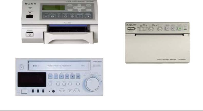
|
4535 612 34161 |
HD3 Service Manual |
Page 33 |
||
|
CSIP Level 1 |
General Information: System Overview |
|||
|
Figure 1-2 |
HD3 Ultrasound System Image Printers and VCR |
|||
UP-21MD Sony Color Printer
UP-895MD Sony Graphic Printer
(Black and White)
HS-MD3000UA/EA Mitsubishi Video Cassette Recorder
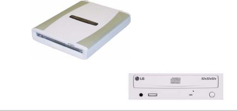
|
4535 612 34161 |
HD3 Service Manual |
Page 34 |
||
|
CSIP Level 1 |
General Information: System Overview |
|||
|
Figure 1-3 |
HD3 Ultrasound System Data Media |
|||
USB MOD Drive
CD-RW Drive
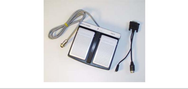
|
4535 612 34161 |
HD3 Service Manual |
Page 35 |
||
|
CSIP Level 1 |
General Information: System Overview |
|||
|
Figure 1-4 |
HD3 Ultrasound System Foot Switch |
|||
|
4535 612 34161 |
HD3 Service Manual |
Page 36 |
|
CSIP Level 1 |
General Information: Physical Description |
|
|
Physical |
The HD3 physical structure is made of fabricated sheet metal and molded plastic parts. The sys- |
|
|
Description |
tem (Figure 1-1) consists of a cart, a user interface (control panel), a visual display (video moni- |
tor), and the ultrasound electronic components. Other important physical components are the power circuits, software and data storage devices, and the system input/output (I/O) connection panel.
See Section 4, “Theory of Operation” for a functional description of these system components.
Cart |
The cart is made up of a base and framework that provides a chassis on which all system compo- |
|
nents are installed and interconnected. |
|
|
Swivel-casters at the four corners of the cart base provide system maneuverability and braking. |
|
|
The front casters can be fixed straight and locked, or unlocked, by foot-operated wheel locks to |
|
|
mobilize or immobilize the system as needed. |
|
|
System Control |
The control panel (Figure 1-5) is a replaceable, self-contained module. |
|
Panel |
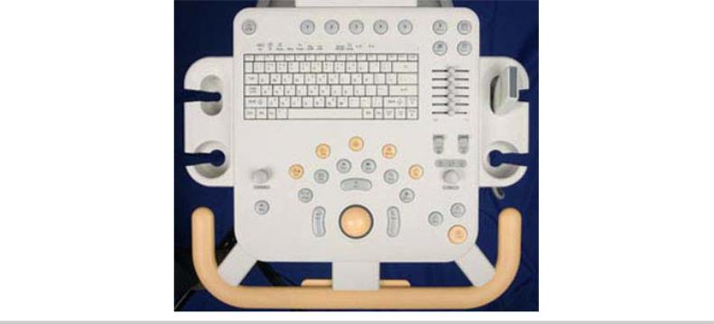
|
4535 612 34161 |
HD3 Service Manual |
Page 37 |
||
|
CSIP Level 1 |
General Information: Physical Description |
|||
|
Figure 1-5 |
HD3 Ultrasound System Control Panel |
|||
System Monitor |
The video monitor (Figure 1-1) is a non-interlace 26.4 cm (10.39-in) color TFT LCD display that |
|
is mounted on a mechanism that allows tilt and swivel positioning of the display. |
|
|
Ultrasound |
The physical components that comprise the primary ultrasound elements of the system are the |
|
Components |
Transducer Connector Assembly and the E-box circuit boards. See Section 13, “Configuration” |
|
for pictures and locations of these system components. |
|
4535 612 34161 HD3 Service Manual |
Page 38 |
|
CSIP Level 1 |
General Information: Physical Description |
Transducer Connector Assembly
The Transducer Connector Assembly (TCA) has the transducer connectors (contained in metal shielding) that interconnect to the E-box Front End board.
E-box
The E-box is a card cage that houses the ultrasound signal generation and echo acquisition circuits. The following ultrasound system electronic circuits are contained in the E-box:
•E-box Motherboard (backplane)
•Front End (FE) Assembly
•Beamformer (BF) Board
•Beamformer-to-Front End Connector (BFC) (physically and electronically connects BF and FE boards)
•Digital Scan Converter (DSC) Board
•PCC Board (embedded computer)
The system electronic power components are the Isolation Transformer, Power Supply, and the Power I/O Assembly.
See Section 14, “Parts” for illustrations and locations of these system components.
|
Software and |
The software and data storage components (Figure 1-3) are physically comprised of the hard disk |
|
Data Storage |
drive (HDD), CD-RW drive, and when installed, the optional magneto-optical disk (MOD) drive. |
|
Components |
|
4535 612 34161 |
HD3 Service Manual |
Page 39 |
|
CSIP Level 1 |
General Information: Device Safety Requirements and Regulatory Compliance |
|
I/O Panel |
The I/O Panel, which provides connections for external devices, is installed into the rear of the |
|
|
cart framing (see Figure 11-5 for connection descriptions). |
||
Cables |
Physical cables provide system signal interconnect and power distribution. Refer to Section 11, |
|
|
“Cabling”, for detailed cable information. |
Device Safety Requirements and Regulatory Compliance
The HD3 Ultrasound System complies with the following requirements for the International Electrotechnical Commission (IEC), the Canadian Standard Association (CSA), and the Underwriters Laboratories (UL).
•IEC60950/EN60950 for data processing equipment
•IEC 60601-1/EN 60601-1for medical equipment
•IEC 60601-1-1/EN 60601-1-1 for medical equipment
•CSA22.2 No. 601.1
•UL 2601-1
For information about applicable safety standards and specifications, see the HD3 Getting Started manual shipped with the system.
|
4535 612 34161 HD3 Service Manual |
Page 40 |
|
CSIP Level 1 |
General Information: Supplies and Accessories |
Supplies and accessories are not available from Philips Ultrasound. The customer is directed to order biopsy guides by contacting their Philips representative or an authorized distributor.
Transducer covers and other supplies and accessories can be ordered from CIVCO Medical Instruments:
CIVCO Medical Instruments
102 First St. South
Kalona, IA 52247-9589
|
Phone: |
(800) 445-6741, Ex. 1 for Customer Service (USA) |
|
+1 319-656-4447 (International) |
|
|
Fax: |
(877) 329-2482 (USA) |
|
+1 319-656-4451 (International) |
|
|
E-mail: |
info@civcomedical.com |
|
Internet: |
www.civco.com |
Open Source
Software
License
The HD3 system uses an embedded computer featuring the Linux operating system, parts of which are open source software. The following notification is included in the customer’s Operating Notes:
This Philips ultrasound system may contain “open source” software. According to the terms of the General Public License, a recipient may request a copy of any GPL-licensed source code modules present in the system, for the cost of shipping and handling. Please contact your local customer service representative for additional information.
The “additional information” is that the customer is entitled to a copy of the operating system software and that you can order it for them if they want it. The part number for the HD3 system Open Source Software is 453561228511.
|
4535 612 34161 HD3 Service Manual |
Page 41 |
|
CSIP Level 1 |
System Specifications: Introduction |
2 System Specifications
Introduction
Physical
Specifications
Electrical
Specifications
This section summarizes the system specifications for the HD3 Ultrasound System. For transducer specifications, see Section 15, “Transducers”.
The physical dimensions and weight of the HD3 are as follows:
•Height:
—Lowest position: 1,280 mm (50.4 in)
—Highest position: 1,455 mm (57.3 in)
•Depth: With no peripherals: 798 mm (31.4 in)
•Width: With no peripherals: 505 mm (19.9 in)
•Weight: Less than 61.2 kg (135 lb.) including monitor, and without peripherals.
The electrical specifications of the HD3 are as follows:
•AC input: 90 to 264 Vac, 47 to 63 Hz
•Ground impedance: 100 mΩ maximum
•Load: 1,150 VA maximum.
•AC output (including PC): non-sinusoidal 120 VRMS, 350 VA maximum
|
4535 612 34161 HD3 Service Manual |
Page 42 |
|
CSIP Level 1 |
System Specifications: Environmental Specifications |
Environmental Specifications
The environmental specifications for the HD3 system are as follows:
•Operational:
—Temperature range: 10°C to +40°C (+50°F to +104°F)
—Relative humidity: 15% to 95% non condensing
—VCR and printers temperature limit: 10°C to +40°C (+50°F to +104°F) at 80% RH
—Altitude: 697 hPa to 1013 hPa (0 to 10,000 feet) at 35°C (95°F)
•Storage:
—Temperature range: –20°C to +60°C (–4°F to +140°F)
—Relative humidity: 15% to 95%, non condensing
—Altitude: 572 hPa to 1013 hPa
Table 2-1 lists the PCC hardware specifications.
|
Table 2-1 |
Embedded PC Hardware Specifications |
|
|
Component |
Specification |
|
|
OS |
Linux |
|
|
Memory |
128 Synchronous DRAM |
|
|
Hard drive |
80 GB |
|
|
VGA |
640×480 |
|
|
ROM |
2 Mbit Flash BIOS |
|
|
Network Interface |
10/100 Mb/s Tx |
|
|
Keyboard |
PS/2 |
|
|
4535 612 34161 HD3 Service Manual |
Page 43 |
||
|
CSIP Level 1 |
System Specifications: Monitor Specifications |
||
|
Table 2-1 |
Embedded PC Hardware Specifications (Continued) |
||
|
Component |
Specification |
||
|
Mouse |
PS/2 |
||
|
IDE port |
Enhanced IDE interface |
||
The monitor specifications are:
•Type: TFT LCD
•Size: 10.4 inch
•Pixel Pitch: 0.33mm x 0.33mm
•640 x 480 VGA at 60 Hz
•Color Depth: 8-bit, 262,144 colors
•Power Consumption: Total 3.5 Watt

|
4535 612 34161 HD3 Service Manual |
Page 44 |
|
CSIP Level 1 |
System Specifications: Image Formats |
The following image storage formats are supported by each HD3 storage device (Table 2-2):
|
Table 2-2 |
Supported Image Formats |
|
Device |
Format |
|||
|
BMP |
JPEG |
TIF |
DICOM |
|
|
Hard Drive |
X |
X |
X |
X |
|
Flash Memory |
X |
X |
X |
X |
|
CD R/W |
X |
X |
X |
X |
|
MOD |
X |
X |
X |
X |
|
4535 612 34161 HD3 Service Manual |
Page 45 |
|
CSIP Level 1 |
Safety: Introduction |
3 Safety
Introduction
About Safety
Information
General
Operating
Safety
This section summarizes the safety information for the HD3 Ultrasound System.
Please read this and related information before using or servicing a Philips ultrasound system. It applies to the ultrasound system, transducers, recording devices, and any optional equipment.
This system is intended for use by, or by the order of, and under the supervision of a licensed physician qualified to direct the use of the device.
In this manual, WARNING is used to indicate the presence of a hazard that can cause personal injury, death, or substantial property damage if the warning is ignored.
In this manual, CAUTION is used to indicate the presence of a hazard that can cause equipment damage if the caution is ignored.
In this manual, NOTE is used when additional comment or explanation is required about installation, operation, or maintenance information that is important but not necessarily haz- ard-related.
Read the HD3 Getting Started for detailed safety and standards information for the HD3 Ultrasound System. This guide includes critical information about the intended uses of the HD3 system, patient and operator safety, and device standards. This is information that maintenance personnel should be aware of.

|
4535 612 34161 HD3 Service Manual |
Page 46 |
|
CSIP Level 1 |
Safety: Electrical Safety |
Electrical
Safety
WARNINGS
This equipment has been verified by a recognized third-party testing agency as a Class I device with Type BF and Type CF isolated patient-applied parts and Type B accessories. For maximum safety observe these warnings:
•Do not connect the ultrasound system to the same circuit used for life-support devices.
•Shock hazards may exist if this system, including all externally mounted recording and monitoring devices, is not properly grounded. Protection against electrical shock is provided by grounding the chassis with a three-wire cable and plug. The system must be plugged into a grounded outlet. The grounding wire must not be removed or defeated.
•To avoid risks of electrical shock and fire hazards, inspect the system power cord and plug on a regular basis. Ensure that they are not damaged in any way.
•Do not remove the protective covers on the system; hazardous voltages are present inside. Cabinet panels must be in place while the system is in use. All internal adjustments and replacements must be made by a qualified Philips Ultrasound field service engineer.
•Do not operate this system in the presence of flammable gases or anesthetics. Explosion can result from electrical ignition.
•To avoid risk of electrical shock hazards, always disconnect the system from the wall outlet before cleaning the system.

|
4535 612 34161 |
HD3 Service Manual |
Page 47 |
||
|
CSIP Level 1 |
Safety: Electrical Safety |
|||
|
WARNINGS |
||||
|
• To avoid risk of electrical shock hazards, always inspect transducers before use: Check the |
||||
|
face, housing, and cable before use. Do not use if the face is cracked, chipped, or torn; the |
||||
|
housing is damaged; or the cable is abraded. |
•To avoid risk of electrical shock, do not use any transducer that has been immersed beyond the specified cleaning or disinfection level.
•All patient-contact devices, such as transducers, pencil probes, and ECG leads must be removed from the patient contact prior to application of a high-voltage defibrillation pulse.
•Connection of optional devices not supplied by Philips Ultrasound could result in electrical
shock. When such optional devices are connected to your ultrasound system, ensure that the total system earth leakage current does not exceed 300 μA.
•Avoid placing the system in an environment that may produce electrostatic discharges (ESD) that could affect the ultrasound system performance. (Electrostatic discharges can cause the ECG heart rate display to increase by 10% to 15% for a few seconds after the discharge, even though the ECG heart rate display returns to normal within a few seconds. See “About Electrostatic Discharge” on page 51.)
•Avoid placing the system in an environment that may produce electromagnetic interference (EMI) that could impact the diagnosis of a patient. (Only a physician can determine if an artifact caused by radiated interference has a negative impact on image quality and the subsequent diagnosis.) See “Avoiding EMI and RF” on page 48.

|
4535 612 34161 HD3 Service Manual |
Page 48 |
|
CSIP Level 1 |
Safety: Electrical Safety |
Avoiding EMI
and RF
CAUTION
Although the system has been manufactured in compliance with existing EMI/EMC requirements, use of this system in the presence of an electromagnetic field can cause momentary degradation of the ultrasound image. If this occurs often, review the environment in which the system is being used, to identify possible sources of radiated emissions. These emissions could be from other electrical devices used within the same room or an adjacent room. Communication devices such as cellular phones and pagers can cause these emissions. The existence of radio, TV, or microwave transmission equipment located nearby can cause emissions. In cases where EMI is causing disturbances, it may be necessary to relocate your system.
Electrosurgical units (ESUs) and other devices intentionally introduce radio frequency (RF) electromagnetic fields or currents into patients. Because imaging ultrasound frequencies are also in the RF range, ultrasound transducer circuits are susceptible to RF interference. While an ESU is in use, the noise generated can severely interfere with the black-and-white image and completely obliterate the color image.
Avoid placing the system in an environment that may produce electrostatic discharges (ESD) that could damage the ultrasound system. (See “About Electrostatic Discharge” on page 51.)

|
4535 612 34161 HD3 Service Manual |
Page 49 |
|
CSIP Level 1 |
Safety: Mechanical Safety |
Mechanical
Safety
WARNINGS.
Although the system is designed to be mobile, remember that it is very heavy, and that you must take precautions when moving it. The physical aspects of this system present a hazard that can cause injury, property damage, or equipment damage if the following information is ignored:
•Before moving the system, be sure to power it off, remove any loose equipment from the top of the system, disconnect the system power cord, and disconnect all external devices. Move and secure external devices away from the system.
•Make sure the control top is locked, to prevent its up/down movement and unlock the caster locks before moving the system. Push with the handle at the front of the cart. After the system is in position, engage the caster locks to immobilize the system.
•Be aware of the casters as well as the extremities of the system when moving it. The system is heavy enough in any configuration that it can cause injury to you or others. Exercise additional caution when going up or down inclines.
•When attempting to overcome an obstacle, do not push the system with enough force to cause it to tip over. Do not exceed 10 degrees of incline.
•Never park the system on an incline.
•For transport, make sure the control top is locked and secure the system so that it cannot roll or tip. Engage the caster locks and use wheel chocks and restraining straps. Do not attempt to hold the system in place manually. Never strap or secure the system at any point on the control top or monitor.

|
4535 612 34161 |
HD3 Service Manual |
Page 50 |
||
|
CSIP Level 1 |
Safety: General Equipment Protection |
|||
|
CAUTIONS |
• Ensure that the cables for all patient-applied parts are secure before moving the system. Use |
the cable management system to ensure that transducer cables are protected from damage.
• Do not roll the system over transducer cables or power cables.
• If the system behaves abnormally after moving or transporting, contact Philips Ultrasound Customer Service immediately. The components can withstand considerable shock, but excessive shock can cause a system failure.
General
Equipment
Protection
Follow these additional precautions to protect the system from damage:
|
CAUTIONS |
• |
For optimal performance, the ultrasound system should be connected to a power circuit |
|
|
dedicated solely for the ultrasound system. |
|||
|
• Verify system and peripheral power sources are appropriate before connecting to them. |
|||
|
• |
Avoid placing the system in an environment that may produce electrostatic discharges (ESD) |
||
|
that could damage the ultrasound system. See “About Electrostatic Discharge” on page 51. |
|||

Характеристики
Расположение:
Стационарный
Режимы:
2D, THI, М, 3D, 4D

В 2005 году компания Philips Medical Systems представила на рынок медицинского оборудования универсальный компактный, высокомобильный, экономичный УЗ сканер с высокой четкостью изображения. В конце 2006 года проведена модернизация системы, данная версия называется Perfomance 2007. Данный прибор отличается наличием цифрового широкополосного формирования УЗ луча на передачу и прием, широким динамическим диапазоном и цифровой фокусировкой, что обеспечивает исключительную чувствительность и разрешающую способность по сравнению с другими приборами данного класса. Ультразвуковой сканер PHILIPS HD 3 самый компактный, удобный в работе и мобильный. Доступный по цене для применения в офисе или больнице, при этом имеет возмозности визуализации и удобства, недоступные в большинстве основных ультразвуковых систем. Компания PHILIPS давно приобрела солидную репутацию производителя ультразвукового оборудования, помогающего сделать диагностику более надежной. Ультразвуковой аппарат HD3 продолжает этот стандарт качества. Система оборудована широкополостным цифровым формирователем луча, позволяющим получить и сохранить более подробную информацию о состоянии тканей по сравнению с обычными ультразвуковыми аппаратами. Благодаря широкому динамическому диапазону и цифровой настройке фокуса достигается исключительная чувствительность и детализация изображения.

Области применения
- Акушерство
- Общее обследование органов брюшной полости
- Исследование сосудов
- Исследование малых органов
- Педиатрия
- Гинекология
- Кардиология
Режимы визуализации
- Двухмерное отображение
- Режим тканевой гармоники (THI)
- Импульсно-волновой доплеровский режим
- М-режим
- Трехмерное сканирование в режиме «свободной руки»
- Цветной доплеровский режим (опция)
- Дополнительная цветная мощная визуализация сосудов (Color Power Angio Imaging (CPA)
- Режим двойного двухмерного/цветного отображения с записью кинопетли (cineloop)
- Дуплекс с одновременным двухмерным изображением и доплерографией
- Триплекс с одновременным двухмерным изображением, доплерографией и цветной/CPA
- Увеличение изображения при записи с высокой разрешающей способностью
- Режим трапецивидного отображения

Основные характеристики
- Число приемо-передающих каналов на 1 кадр изображения — 256
- Акустический динамический диапазон (представленный на мониторе) — 150 дБ
- Максимальная глубина сканирования – 24 см
- Максимальная частота кадров – 90 в сек
- Коннекторы для подключение датчиков не менее 2 (3й порт – опция)
- Большое число режимов сканирования и областей применения
- Черно-белая и цветная визуализация с высоким разрешением
- Яркий жидкокристалический монитор без дрожания изображения. Размером 12 дюймов, регулировка – поворот и наклон (возможностьскладывания для транспортировки)
- Регулировка панели управления по высоте (вместе с монитором) и поворот
- Режим просмотра кинопетли (Cineloop)
- Легкие в применении органы управления
- Оптимизация изображения нажатием одной клавиши
- Малый вес, мобильность и эргономичная конструкция
- Гармоническая тканевая визуализация
- Пакеты анализа, включающие полный набор измерений, расчетов и отчетов
- HDD 75Гб
- Система архивации на CD и CD-RW
- USB-порт на передней панели для подключения USB-flash
- Экспорт данных в форматах JPEG, BMP, TIF, DICOM
- Полная русификация прибора
- Возможность ввода фамилий пациентов на русском языке
- Периферийные устройства (опция): видеомагнитофон, черно-белый термовидеопринтер, цветной термовидеопринтер, РС принтер, ножной переключатель
Датчики применяемые с ультразвуковым аппаратом PHILIPS HD 3
Типы поддерживаемых датчиков:
конвексные, линейные, микроконвексные (в т.ч внутриполостные).
- C5-2 Широкополосный конвексный датчик для абдоминальных исследований в режимах 2D, импульсно-волновой, а также цветовой и энергетической допплерографии, поддерживающий технологию тканевой гармоники Диапазон частот 2 — 5 МГц
- C7-3 Широкополосный конвексный датчик для общих и педиатрических абдоминальных исследований, акушерства и гинекологии.Диапазон частот 3 — 7 МГц
- L9-5 Широкополосный линейный для исследования близкорасположенных органов, сосудов и опорно-двигательного аппарата в режимах 2D, импульсно-волновой, а также цветовой и энергетической допплерографии с трапециевидным режимом. Диапазон частот 5 – 9 МГц
- С9-4ес Широкополосный микроконвексный датчик для внутриполостных ректовагинальных исследований . Диапазон частот 4 — 9 МГц, радиус кривизны 10мм, сектор обзора 150гр
- C4-2 Широкополосный конвексный датчик для кардиологических исследований в режимах 2D, импульсно-волновой, а также цветовой и энергетической допплерографии, поддерживающий технологию тканевой гармоники. Диапазон частот 2 — 4 МГц
- С9-4 Широкополосный микроконвексный датчик для педиатрических исследований, нейросонографии .Диапазон частот 4 — 9 МГц, радиус кривизны 10мм, сектор обзора 150гр
- Комплект биопсийных насадок для датчиков С5-2, С7-3, L9-5, C9-5ec (опция)
Характеристика электропитания
- Напряжение/частота 220 В / 50 Гц.
- Размеры: глубина 80см, ширина 51см, высота 97-146см (регулируется)
- Вес 61кг
Ультразвуковой сканер PHILIPS HD 3 самый компактный, удобный в работе и мобильный сканер, имеет возмозности визуализации и удобства.
Обращаем Ваше внимание на то, что данная информация ни при каких условиях не является публичной офертой.
Политика в отношении обработки персональных данных
|
Хранилище файлов |
Правила добавления:
Внимание !!!
Перед тем как загрузить файл, убедитесь, что его нет в «Хранилище файлов» для этого воспользуйтесь поиском.
При добавлении файлов в поле «Название материала» указываем марку аппарата, так как на шильдике или по паспорту.
В поле «Краткое описание» пишем что-это: схема; сервис мануал; руководство по эксплуатации и т.д. Также напишите формат материала, какой программой он сделан.
За сохранность и работоспособность файлов(ссылок) загруженных на сторонние файловые хостинги, Администрация сайта ответственности не несет.
Для загрузки файлов в «Хранилище» воспользуйтесь архиватором WinRAR или 7-Zip, максимальный объем загружаемого файла должен быть не более 15Mb.
Администрация сайта оставляет за собой право удалять и редактировать файлы.
Для скачивания с 4Shared.com необходимо зарегистрироваться и создать аккаунт на 4shared.com или пользоваться другим способом скачивания которые там же предлагаются.
Philips HD3 service manual
Гостям запрещено просматривать данную страницу, пожалуйста войдите на сайт как пользователь.
[
Регистрация
|
Вход
]
| 24.Сен.2014, 08:52 | |
| Категория: Аппараты УЗИ | |
| Просмотров: 2973 | Загрузок: 352 | Размер: 5.85 Mb |
Вопросы по ремонту медицинской техники | Теоретические основы медицинского приборостроения | Информационный раздел | Информация о сайте | Хранилище файлов | Сертификаты и регистрационные удостоверения | Навигатор по сайту |
Написать администратору

| Производится |
| Тип: стационарный |
| Класс: средний |
| Дисплей: ЖК, 12 дюймов |
| Режимы сканирования: 2D, THI, М, 3D, 4D |
| Режим тканевой гармоники |
| Импульсно-волновой доплеровский режим |
В ультразвуковой системе HD3 от известного производителя Philips гармонично сочетаются высокое качество визуализации, инновационные технологии, многофункциональность, удобная эксплуатация, а также приемлемая стоимость. Аппарат оснащен большим жидкокристаллическим монитором с диагональю 12 дюймов.
Преимущества HD3 от Philips
 Высокая чувствительность и разрешающая способность. HD3 Philips имеет возможность цифрового широкополосного формирования ультразвукового луча на прием и передачу, широкий динамический диапазон, цифровую фокусировку, что позволяет добиться высокого уровня разрешения и чувствительности. С данной ультразвуковой системой пользователь никогда не будет сомневаться в достоверности выполненных обследований.
Мобильность и эргономичность. Отличительная особенность УЗ-сканера HD3 Philips заключается в его небольших габаритах: несмотря на то, что это стационарная система, она, в отличие от многих других моделей УЗИ-сканеров, имеет небольшой вес и легко размещается в небольших пространствах.
Эффективность работы. УЗИ-специалист может получать и сохранять всю необходимую информацию о состоянии тканей. Изображения всегда отличаются высоким уровнем детализации, которая стала возможна благодаря применению широкого динамического диапазона и цифровой настройки фокуса.
Области применения:
- Исследование малых органов
- Акушерство
- Гинекология
- Общее обследование органов брюшной полости
- Педиатрия
- Кардиология
- Исследование сосудов
Режимы сканирования
Используемые режимы визуализации:
 Режим тканевой гармоники (THI)
- Импульсно-волновой доплеровский режим
- Увеличение изображения при записи с высокой разрешающей способностью
- Режим трапецивидного отображения
- М-режим
- Трехмерное сканирование в режиме «свободной руки»
- Цветной доплеровский режим (опция)
- Дополнительная цветная мощная визуализация сосудов (Color Power Angio Imaging (CPA)
- Двухмерное отображение
- Режим двойного двухмерного/цветного отображения с записью кинопетли (cineloop)
- Дуплекс с одновременным двухмерным изображением и доплерографией
- Триплекс с одновременным двухмерным изображением, доплерографией и цветной/CPA
 Режим тканевой гармоники (THI)
Технические характеристики
В данной таблице представлены основные физические характеристики УЗИ-сканера:
|
Монитор |
ЖК монитор без дрожания изображения. Размером 12 дюймов, регулировка – поворот и наклон (возможность складывания для транспортировки) |
|
Тип визуализации |
Черно-белая и цветная визуализация с высоким разрешением |
|
Гармоническая тканевая визуализация |
есть |
|
Коннекторы для подключение датчиков |
не менее 2 (3й порт – опция) |
|
Возможность ввода фамилий пациентов на русском языке |
есть |
|
Максимальная глубина сканирования |
24 см |
|
Экспорт данных |
в форматах JPEG, BMP, TIF, DICOM |
|
Cineloop |
Режим просмотра кинопетли |
|
HDD |
75Гб |
|
Акустический динамический диапазон (представленный на мониторе) |
150 дБ |
|
Регулировка панели управления |
по высоте (вместе с монитором) и поворот |
|
Общий вес прибора |
61 кг |
|
Общие габариты |
глубина 80см, ширина 51см, высота 97-146см (регулируется) |
|
Напряжение/частота |
220 В / 50 Гц. |
|
Число приемо-передающих каналов |
на 1 кадр изображения — 256 |
|
Пакеты анализа, включающие полный набор измерений, расчетов и отчетов |
есть |
|
Оптимизация изображения |
нажатием одной клавиши |
|
Система архивации |
на CD и CD-RW |
|
Максимальная частота кадров |
90 в сек |
|
Периферийные устройства (опционально) |
видеомагнитофон, черно-белый термовидеопринтер, цветной термовидеопринтер, РС принтер, ножной переключатель |
|
USB-порт на передней панели |
Используется для подключения USB-flash |
Датчики
- C5-2 Широкополосный конвексный датчик для абдоминальных исследований в режимах 2D, импульсно-волновой, а также цветовой и энергетической допплерографии, поддерживающий технологию тканевой гармоники Диапазон частот 2 — 5 МГц
- C7-3 Широкополосный конвексный датчик для общих и педиатрических абдоминальных исследований, акушерства и гинекологии.Диапазон частот 3 — 7 МГц


- L9-5 Широкополосный линейный для исследования близкорасположенных органов, сосудов и опорно-двигательного аппарата в режимах 2D, импульсно-волновой, а также цветовой и энергетической допплерографии с трапециевидным режимом. Диапазон частот 5 – 9 МГц
- С9-4ес Широкополосный микроконвексный датчик для внутриполостных ректовагинальных исследований . Диапазон частот 4 — 9 МГц, радиус кривизны 10мм, сектор обзора 150гр
- C4-2 Широкополосный конвексный датчик для кардиологических исследований в режимах 2D, импульсно-волновой, а также цветовой и энергетической допплерографии, поддерживающий технологию тканевой гармоники. Диапазон частот 2 — 4 МГц
- С9-4 Широкополосный микроконвексный датчик для педиатрических исследований, нейросонографии .Диапазон частот 4 — 9 МГц, радиус кривизны 10мм, сектор обзора 150гр
- Комплект биопсийных насадок для датчиков С5-2, С7-3, L9-5, C9-5ec (опция)
- Главная страница
- Каталог
- Медицинское оборудование
- Ультразвуковая диагностика (УЗИ аппараты)
- Ультразвуковые сканеры Philips
Компактная и удобная в эксплуатации мобильная система высокого разрешения.
В настоящий момент не поставляется. Вас могут заинтересовать аналоги: УЗИ сканеры Mindray
В избранное
В сравнение
Доставка по всей России
Сроки уточняйте у оператора
- Описание
Ультразвуковой сканер Philips HD3
Когда от ультразвукового сканера требуются небольшие размеры, малый вес и простота использования – на помощь приходит Philips HD3. Эта система УЗИ полностью отвечает этим требованиям, при этом обладает превосходным качеством изображения и широким функционалом.
Применение технологий, используемых в аппаратах более высокого уровня, обеспечивает исключительную чувствительность и детализацию изображения. Продуманная эргономика существенно уменьшает нагрузку на пользователя. Ультразвуковая система Philips HD3 позволяет расширить клинические возможности и спектр обследований.
Области применения HD3
- Абдоминальные исследования.
- Исследования поверхностных /малых объектов.
- Педиатрические исследования.
- Акушерские исследования.
- Гинекологические исследования.
- Урологические исследования.
- Сосудистые исследования.
- Кардиологические исследования.
Режимы визуализации
- Двухмерная визуализация (2D).
- Режим второй гармоники (THI).
- Режим импульсно-волновой (PW) допплерографии.
- M-режим.
- Режим 3D методом свободной руки.
- Режим цветовой скоростной и энергетической допплерографии.
- Дуплексный режим 2D/ЦДК с просмотром кинопетель.
- Дуплексный режим 2D/PW.
- Триплексный режим 2D/ЦДК/PW.
- Возможность увеличения изображений с высоким разрешением.
- Трапециевидное изображение.
Архитектура системы Philips HD3
- Полностью цифровой широкополосный формирователь луча.
- Двухмерная фокусировка с динамической фокальной настройкой.
- Градации серого — 256 (8 бит) в двухмерном режиме, M-режиме и в режиме спектральной допплерографии.
- 256 градаций цвета (8 бит) в режиме ЦДК Монитор.
- Плоский жидкокристаллический дисплей с высоким разрешением и размером 29,5 см на 31,5 см (включая обрамление) с полезной рабочей областью экрана 12 ,1 дюйма. Встроенные стереодинамики.
Датчики
- Система поддерживает линейные, конвексные и микроковексные датчики.
- Три порта для подключения датчиков.
- Электронное переключение датчиков.
- Постоянная динамическая фокусировка.
Возможности подключения и хранения
- Запоминающее устройство в виде встроенного жесткого диска объемом 75 Гбайт.
- Стандартное устройство для записи (CD–R/RW) компакт-дисков.
- Поддержка запоминающих устройств, подключаемых к USB-порту.
- Возможность экспорта изображений на USB-устройства флэш-памяти или компакт-диск для просмотра на ПК в различных форматах хранения изображений (JPG, BMP, TIF, DICOM).
- Выход 10BaseT Ethernet.
- Настраиваемый IP-адрес.
- Отчеты по исследованиям доступны в виде изображений в формате DICOM.
Периферийные устройства
- Кассетный видеомагнитофон.
- Черно-белый термопринтер.
- Цветной принтер Sony.
- Система поддерживает ряд принтеров, печатающих на обычной бумаге.
Мы гарантируем
Гарантия производителя и продавца
Профессиональные консультации и поддержка на каждом этапе
Собственный сервисный центр
Демократичная цена и лизинг
Быстрая и бережная доставка
Частые вопросы
Стоимость-
Вопрос: Почему на многие товары не указана цена?
Ответ: Итоговая стоимость оборудования зависит от множества факторов:1) Конфигурация. Многие модели медицинского оборудования являются модульными системами. По желанию клиента некоторые модули могут быть добавлены или исключены из поставки. Яркий пример – ультразвуковые сканеры, каждый из которых может комплектоваться различными наборами датчиков (на выбор из нескольких десятков) и дополнительными модулями (например, для расчетов и 4d-исследований). Таким образом, один и тот же УЗ-сканер может иметь несколько десятков конфигураций, значительно различающихся по цене.
2) Стоимость доставки. Мы предлагаем несколько вариантов доставки, из которых наши клиенты могут выбрать наиболее приемлемый по скорости и цене. Подробнее…
3) Установка и наладка. Многие виды оборудования требуют обязательной установки и наладки с помощью сертифицированного специалиста, выдающего акт ввода в эксплуатацию, что так же сказывается на стоимости.
4) Курс валюты, сроки поставки и прочие менее значимые факторы.
Совет: Если вы видите в каталоге какой-либо компании точную цену на медицинское оборудование – обязательно уточняйте, что входит в эту сумму!
Скидки! У нас действует гибкая система скидок, постоянно проводятся специальные акции и действуют другие привлекательные предложения. Следите за новостями!
Доставка-
Территория доставки?
ТИАРА-МЕДИКАЛ осуществляет доставку медицинского оборудования в пределах Таможенного Союза (ЕврАзЭС) транспортными компаниями. За 10 лет работы мы установили тесные партнерские отношения с различными транспортными компаниями и предлагаем нашим покупателям наиболее выгодные варианты доставки.
В каких случаях бесплатная доставка?
Доставка по Санкт-Петербургу – БЕСПЛАТНО.
Доставка до транспортных компаний – БЕСПЛАТНО.
Лизинг-
Компания ТИАРА-МЕДИКАЛ имеет многолетний опыт продажи медицинского оборудования в лизинг. Мы сотрудничаем с лизинговыми компаниями, выбранными покупателем, или можем порекомендовать наших проверенных партнеров.
Какое оборудование можно купить в лизинг?
В лизинг предоставляется оборудование для УЗИ, томографии, рентгенологии, эндоскопии, офтальмологии, косметологии. А также любое медицинское оборудование стоимостью от 1 000 000 рублей. Обратитесь за расчетом выгодного приобретения в лизинг к нашим специалистам по телефону: 8 (800) 500-26-76
Как быстро принимаем решение?
Срок рассмотрения от 1 дня.
С какими лизинговыми компаниями мы сотрудничаем?
В основном с «Элемент лизинг» и «Балтийский лизинг», также готовы работать с другими компаниями, которые выгодны и удобны для Вас.
Сервис-
Мы создали лучшую систему сервисной поддержки медицинского оборудования, на протяжении всего срока службы. В нашей команде работают высококвалифицированные инженеры, систематически совершенствующие свои навыки на заводах производителей мед. оборудования. Мы оказываем исчерпывающий спектр услуг по поддержке и ремонту оборудования.
При поставке мы предлагаем
Установку, настройку, ввод в эксплуатацию (по всей территории РФ).
Обслуживание после поставки
Наш собственный лицензированный сервисный центр производит:
— Гарантийное и пост-гарантийное комплексное обслуживание медицинской техники.
— Гарантийный и пост-гарантийный ремонт.
— Выездной инструктаж пользователей.
— Поддержку документацией и учебными материалами.
— Консультации на любом этапе использования.Отдел запчастей медицинского оборудования
Подбор и продажа оригинальных запчастей для медицинской техники.
Гарантии-
ТИАРА-МЕДИКАЛ осуществляет продажу медицинского оборудования, инструментов и материалов в соответствии с законодательством РФ. Наше оборудование имеет всю необходимую разрешительную документацию, гарантию производителя и продавца.
Гарантийный срок на медицинское оборудование
Срок базовой гарантии на мед. оборудование составляет 12 месяцев со дня покупки и может быть увеличен в зависимости от индивидуальных гарантийных условий производителя!
Как заказать гарантийное обслуживание
Гарантийное сервисное обслуживание осуществляется по запросу в сервисный центр ТИАРА-МЕДИКАЛ. Звоните по тел.: 8 (800) 500-26-76 или оставьте заявку на странице сервисного центра
Кто проводит обслуживание медицинского оборудования
Мы имеем собственный лицензированный сервисный центр для обслуживания и устранения неисправностей и команду сертифицированных специалистов выездного обслуживания техники. Работы проводятся согласно стандартам производителя. Доставляем оборудование в сервисный центр — бесплатно!
Наши специалисты готовы на них ответить, рассказать об оборудовании и помочь с выбором.