Порядок проведения имитационной игры в информационной системе «Арена»
С целью ознакомления с работой информационной системы «Арена», выработки и практической реализации определенных стратегий хеджирования риска изменения цены на электроэнергию, приглашаем принять участие в имитационной игре, которую планируется провести с 28 мая 2007 г. по 11 июня 2007 г. Принять участие в имитационной игре может любой субъект ОРЭМ, как действующий, так и планирующий выход на ОРЭМ, ГТП которого находится в любой ценовой зоне.
Процедура допуска к имитационной игре:
Для того, чтобы принять участие в имитационной игре, следует выполнить следующее:
- Заполнить Анкету участника имитационной игры и отправить ее по электронной почте по адресу info@arena—trade.ru.
На адреса электронной почты пользователей системы, указываемых в разделе 5 анкеты, будут отправляться уведомления, связанные с обработкой СДД, поэтому эти адреса должны быть реальными;
Остальные поля анкеты могут быть заполнены фиктивными значениями. Однако, значения этих полей будут использованы при автоматическом заполнении формы договора, который «Арена» будет предлагать контрагентам для подписания. Поэтому в целях проверки корректности заполнения формы рекомендуется указать реальные либо приближенные к реальным значения.
- Удостовериться, что выполнены требования к программным и техническим средствам.
- Операционная система Windows (98/2000/XP).
- Оперативная память — от 512Мб.
- Процессор с тактовой частотой от 1ГГц.
- Броузер Internet Explorer 6 (Service Pack 1) или выше.
- MS Office 2000 или более поздний (MS Office XP).
При установке должна быть включена поддержка OWC (Office Web Components) — по умолчанию эта поддержка включена.
Эти компоненты используются для просмотра выводимых графиков. - Для соединения предпочтительно использовать выделенную линию.
(Требования к компьютеру пользователя и сетевому соединению могут быть и ниже. Работоспособность системы в этом случае сохранится, при этом возможно замедление некоторых процессов).
На адрес, указанный в поле «Адрес электронной почты (для переписки)» анкеты администратором будет отправлен файл с сертификатом, который на период имитационных торгов будет ключом для входа в систему.
Вместе с сертификатом будут отправлены:
- инструкция по установке данного сертификата на ваш компьютер;
- руководство пользователя системы «Арена».
- Терминал пользователя системы доступен через Интернет по адресу https://arena-trade.ru
В режиме имитационной игры доступны все функциональные возможности системы. Отличия от «боевого» режима таковы:
- В «боевом» режиме при обоюдном подписании СДД контрагентами происходит автоматическая отправка необходимых документов на регистрацию в НП «АТС». В режиме имитации в НП АТС документы в НП «АТС» не отправляются, а функции НП АТС (прием и регистрация договоров) имитируются администратором системы «Арены».
- Перечень типов контрактов, допущенных к обращению на период имитационной игры будет опубликован на сайте системы «Арена».
- В период имитационной игры использование системы «Арена» является бесплатным.
- Таким образом, участие в имитационной игре не несет никаких финансовых последствий для участников как на ОРЭМ, так и перед ООО «Арена».
Все пожелания и предложения по функционированию системы, которые возникают у вас в процессе участия в имитационной игре, можно:
- отправлять по электронной почте на адрес info@arena—trade.ru
- сообщить по телефонам в Москве (495) 660-31-24; 8-903-762-54-77.
- Manuals
- Brands
- Honeywell Manuals
- Software
- ARENA
- User manual
-
Contents
-
Table of Contents
-
Bookmarks
Quick Links
ARENA / RANGER
User Guide
Copyright © 2008 Honeywell GmbH ● All Rights Reserved
EN2Z-0906GE51 R0708
Related Manuals for Honeywell ARENA
Summary of Contents for Honeywell ARENA
-
Page 1
ARENA / RANGER User Guide Copyright © 2008 Honeywell GmbH ● All Rights Reserved EN2Z-0906GE51 R0708… -
Page 2
ARENA / RANGER USER GUIDE EN2Z-0906GE51 R0708… -
Page 3
ARENA / RANGER ARENA / RANGER USER GUIDE This document supports software that is proprietary to Honeywell GmbH, Honeywell Software License Advisory Control Systems Ltd, and/or to third party software vendors. Before software delivery, the end user must execute a software license agreement that governs software use. -
Page 4
ARENA / RANGER USER GUIDE EN2Z-0906GE51 R0708… -
Page 5: Table Of Contents
Creating Local Site ………………44 Create Remote Site through iLON 10 …………45 Create Remote Site through ARENA…………. 54 Cross Reference of iLON 10 Settings and ARENA Settings……59 Edit Site Details ………………..60 Delete Site………………….61 Connect / Disconnect Site ……………… 62 Create Subsystem………………..
-
Page 6
……………………… 140 Alias Name and NV Name Correspondents for SERVAL Controller ….140 Font Size Setting………………..141 Arena Editor ………………….. 142 ARENA Editor Environment …………….143 Menu Bar………………….. 144 Tool Bar………………….145 Panel Window ………………..146 Drawing Space ………………..146 Drawing Tools Pane ……………… -
Page 7: Overview
ARENA is designed to be used on a standard PC. The primary purpose of the ARENA program, is to gather a wide variety of data and display it to the user in an easy to understand graphical format for viewing and easy operation.
-
Page 8: Arena / Ranger Versions
This access restriction provides a very high degree of system protection against accidental or malicious damage. ARENA can be equipped with individual graphic data and will be able to display selected information in a graphical environment. The tool to be used to create graphic templates and graphic navigations is the ARENA EDITOR.
-
Page 9: System Architecture
System Scenarios System with Supervisor ARENA (middle) ARENA acts as central for the local site and as supervisor for the remote site(s) System with Remote ARENA (bottom) ARENA acts as gateway between the supervisor ARENA and the local bus. The connection can be established via modem or any TCP/IP (e.g.
-
Page 10
ARENA. Dial-out Dialing occurs from the remote site to the supervisor ARENA. Dial-out is initiated by a controller (in case no ARENA is available on the remote site) or by the remote ARENA. Dial-up Dial-in or dial-out behavior… -
Page 11: Start Arena
ARENA is started and the ARENA Login screen is displayed. 2. Enter your User Name and your Password. 3. In Operation Mode, select: Text, if you want to operate ARENA in the common text-based way (Site tree visible). In the Text operation mode, the default display shows the following: –…
-
Page 12
ARENA / RANGER USER GUIDE For detailed description of the main window and its functions, please refer to “ARENA Environment “section. EN2Z-0906GE51 R0708… -
Page 13: Arena Environment
The tree structure varies depending on the operating mode (online=connected, offline=disconnected) and on the system architecture that is, on whether you are on a local ARENA connecting to a local site or to a remote site with/without ARENA, and other scenarios.
-
Page 14
ARENA / RANGER USER GUIDE Fig. 2. Site Display Modes in Tree Depending on the current operating status (online= connected) or (offline= disconnected), the sites are indicated differently. A connected site is displayed in full color; a disconnected site is displayed in transparent color. A red triangle with exclamation mark may appear which indicates an unacknowledged alarm. -
Page 15
Fig. 4. Example: Menu display in the Information and Editing pane Sizing the Pane Displays The size of the pane display can be varied by moving the separator horizontally to the left or right. ARENA will remember the corrected width when coming back or restarting the software. EN2Z-0906GE51 R0708… -
Page 16
Configuration menu. In the toolbar, the path of the selected item is displayed Example: You are in: GE51WDTKSAMMET.global.ds.honeywell.com » Configuration » User Administration. On the Information and Editing pane, the corresponding data and properties of the selected item/menu are displayed. -
Page 17
USER GUIDE ARENA/ RANGER To edit item properties, select tree item, e.g. HEATING PLANT, and then select tab, e.g., Datapoints, and click item you want to edit. Example: Datapoint editing in the Information and Editing pane for a selected datapoint of a PANTHER controller. -
Page 18: Basic Functions
, you can logout. Context Sensitive Online Help Clicking on the Help icon displays the ARENA online help in PDF format. Basic Functions The properties of a selected item in the tree, for example, a PANTHER controller, are displayed on tabs on the right pane.
-
Page 19
USER GUIDE ARENA/ RANGER Depending on the user privileges, data can be modified by clicking the appropriate buttons, such as Print, Save, Delete, etc, or by using allocated icons, for example the Configure icon of a datapoint. An underlined item in a list indicates that this entry links to a further dialog showing more details of the item. -
Page 20
ARENA / RANGER USER GUIDE Further Button Functions NEW / GO / SCAN / DELETE / others Those kind of specific buttons perform functions as the button name indicates in its functional context. Multiselection of Items Clicking the checkbox in the title line of a list, Simultaneously selects all entries in the list. -
Page 21
Defines which filter is used by default for the list display NOTE: The filter definitions apply to all local users of the ARENA. 1. At the bottom of the list, click the Configuration button. The Variable List Configuration dialog box displays. -
Page 22
ARENA / RANGER USER GUIDE e. Click the upward or downward buttons. 4. Click the OK button so save settings or continue with: a. Setting the sort order within a column and/or (step b. Setting the default filter display (step 7 ). -
Page 23
USER GUIDE ARENA/ RANGER Under Filtering, all displayed columns of the list and their current filter setting is shown. By default, no particular filter is used (All), that is, all items are displayed. Depending on the column property, e.g. Name or Value/Unit, you can select different particular items which you want to filter for display. -
Page 24
ARENA / RANGER USER GUIDE 1. To apply a filter, click in the field and do one of the following: a. select the filter criterion, for example, ´Digital` in the Type column if you want to display digital datapoints only. -
Page 25: Usage Of Illegal Characters
Using any of these characters may result in an unexpected behavior of ARENA. Date and Time Format Display Settings The display of date and time as it used in various lists within ARENA depends on the language settings for the browser. To get the desired format displayed, set the corresponding language to the highest priority as desribed in the “Internet…
-
Page 26
ARENA / RANGER USER GUIDE ARENA Service The underlying software of ARENA is the service, named ARENA service or simply service. This service is accessible in the system tray and is indicated there as square service icon . The actual operating mode of the service is indicated by different colors of the service icon: •… -
Page 27: Show Arena Version Information
The names of the items (e.g. sites, controllers, datapoints, NVs, etc.) are displayed in a tree as in ARENA and can be picked. Changing of alias names in ARENA will not be reflected in the graphics and after the renaming in ARENA, the data binding will still work.
-
Page 28: Manage Library
4. To import new or other segments via .CSL file, click Browse and select the CSL file. Then click Open. CSL files are provided by Honeywell CentraLine and EN2Z-0906GE51 R0708…
-
Page 29: Licensing
Service dialog box. NOTE: As long as the service is running, all online changes will be stored to the ARENA database (e.g. trend data will be collected) even if the ARENA user interface is not started. Exit 1.
-
Page 30: User Administration
ARENA he is logged in. All users having a role higher than or equal to the assigned role will have this user privilege enabled in ARENA, all others will not.
-
Page 31: Invoke User Administration
You have not to login again, even when going to another site (e.g. to an ARENA remote site), as long as on that site a user with the same user name and password exists.
-
Page 32: Create New User
ARENA / RANGER USER GUIDE Create New User 1. Click Create new user button. RESULT: The Edit/Create new user dialog is displayed. EN2Z-0906GE51 R0708…
-
Page 33
Sites to which the user has no access are disabled (gray). When the user administration is invoked for a remote ARENA selected in the tree, the users will be administered for that site. Then the sites of the remote ARENA are listed here. -
Page 34: Edit User
ARENA / RANGER USER GUIDE 12. Click Save button. RESULT: The created user is displayed in the Users list. Edit User 1. In the Users list, click on the user name you want to edit, then click the Edit button in the corresponding line.
-
Page 35: Delete User
USER GUIDE ARENA/ RANGER 2. Edit desired properties. For description of the properties, please refer to the “Create New User” section. 3. Click Save button. Delete User 1. In the Users list, click on the user name you want to delete, then click the Delete button in the corresponding line.
-
Page 36
ARENA / RANGER USER GUIDE 1. Hover the cursor over the Configuration icon and click Password in the menu. 2. In Old password, enter the current password. 3. In New Password, enter the new password. 4. In Repeat new password, enter the new password. -
Page 37: Site Management
ARENA supports an automatic disconnect mechanism for sites connect via modem: After a definable time, ARENA pops up a dialog that asks you if you want to remain connected. You can decide whether to “remain connected for another X minutes” or to disconnect.
-
Page 38
Automatic disconnection prevents “forgetting to close a connection”. It is used for modem connections only. NOTE: If a remote site is disconnected, the supervisor ARENA has a time out of up to 2 minutes before the tree gets refreshed to indicate offline state. -
Page 39: Remote Site With Arena
When connecting to a site without physically connecting to it, only historical trend and alarm data will be available. This means that a supervisor ARENA will be able to store alarms and trend from other sites. When switching to a local site, you will be automatically connected.
-
Page 40: Remote Site With Ilon 10
When connecting from a Supervisor ARENA, the Supervisor ARENA shows the Supervisor ARENA Web-front end of the remote ARENA in the same way as if it was locally connected. The site name is displayed on top of each page, so that you know on which site you are currently working.
-
Page 41: Supervisor Arena
Connecting the Supervisor ARENA via iLON 10 shows the Web front-end of the Remote Site Display remote site in the same way as if the ARENA is locally connected. The site name is displayed on top of each page, so that you know on which site you are currently working.
-
Page 42: Show Sites Overview
If the remote site of an ARENA-ARENA via LAN site combination is disconnected, Timeout after Disconnection the supervisor ARENA has a time out of up to 2 minutes before the tree gets refreshed to indicate offline state. Show Sites Overview 1.
-
Page 43
SERVAL Fig. 11. “Remote Through ilON 10” Site Type • Remote through ARENA Creates a remote site to an ARENA. Site connection is established via modem , TCP/IP, or VPN (virtual private network). This site type must be selected to connect an ARENA to a Supervisor ARENA. -
Page 44: Creating Local Site
When creating a local site, continue with “Create Local Site” section. When creating a remote site through iLON 10, continue with “Create Remote Site through iLON 10” section. When creating a remote site through ARENA, continue with “Create Remote Site through ARENA” section. Creating Local Site 1.
-
Page 45: Create Remote Site Through Ilon 10
This will make ARENA use the ´Local Area Connection 2` for connections to the iLON 10. The entry can stay as it is installed as long as the ARENA PC has only 1 LAN interface card or as long as there are no problems with iLON 10 LAN connections.
-
Page 46
3. Create Remote Site through iLON 10 via TCP/IP The following descriptions refer to an Example of a typical scenario of a Supervisor ARENA – iLON 10 configuration via LAN as shown in the graphic below. EN2Z-0906GE51 R0708… -
Page 47
Enabled: checked for receiving alarms and iLON Outgoing Connection Incoming Connection iLON 10 address settings: configuration changes IP address, subnet mask, gateway address unchecked: for maintenance by ARENA only iLON Configuration iLON Settings User name: default = ilon Password: default = ilon… -
Page 48
ARENA / RANGER USER GUIDE 5. Under Outgoing Connection to Remote Site do the following: a. Check Enable if you want to use ARENA for dialing-in to a remote site. b. Uncheck Enable if ARENA is only used for receiving alarms. Example:… -
Page 49
USER GUIDE ARENA/ RANGER a. Check Enable if you want the supervisor ARENA enable to receive alarms via the iLON 10 on the remote site. b. Uncheck Enable if you not want the supervisor ARENA to receive alarms. Checking Enable is necessary if you want to customize the iLON 10 by overwriting the default configuration with the settings entered in Outgoing connection to Remote Site. -
Page 50
9. Create Remote Site through iLON 10 via Modem The following descriptions refer to an Example of a typical scenario of a Supervisor ARENA – iLON 10 configuration via modem as shown in the graphic below. Monitoring (Home) Site (A) -
Page 51
In User Name, enter the user name which is used by iLON 10 to authenticate connections from the supervisor PC, i.e. ARENA. In the Windows Dial-Out connection to the site, this user name will be used to contact the site. In the iLON 10 configuration (section «Security»), this setting will be stored as user… -
Page 52
This is the phone number which the remote site uses to contact the PC on which ARENA is running. In the iLON 10 configuration (section «PPP»), this setting will be stored as phone number for outgoing PPP connections. -
Page 53
10. 14. Click OK button. The iLON 10 configuration data are sent to the iLON 10. Note that only if the iLON 10 has been reached and configured successfully, ARENA saves the site configuration. EN2Z-0906GE51 R0708… -
Page 54: Create Remote Site Through Arena
ARENA / RANGER USER GUIDE Create Remote Site through ARENA 1. If not already done, select “Remote Site through ARENA” in New site of type on the Sites Overview pane, and then click the Add button. 2. Under General, do the following: a.
-
Page 55
In Remote Site Address or IP Address, enter the URL or the IP Address of the remote ARENA PC. d. Under Connect, select Directly if you want to connect to the remote ARENA without an ISP (Internet Service Provider). Select Dial to ISP first using if you want to connect via ISP (dial-up). -
Page 56
– Yahoo cannot be used as ISP because there are issues on the provider side concerning external email access. Use an alternative ISP. – ARENA shows all dial-up connections on your PC here, except the ones used to connect to remote sites. ARENA will also allow creating new Dial-up connections to ISPs, which is the recommended way for alarm forwarding. -
Page 57
In User Name, enter the user name. b. In Password, enter the password for the user. NOTES: – User name and password of the supervisor ARENA must match the user name and password under Incoming connection from remote site on the remote ARENA. -
Page 58
In Remote Site Address or IP Address, enter the URL or the IP Address of the remote ARENA PC. Under Connect, select Directly if you want to connect to the remote ARENA without an ISP (Internet Service Provider, see NOTES below). Select Dial to ISP first using if you want to connect via ISP (dial-up). -
Page 59: Cross Reference Of Ilon 10 Settings And Arena Settings
ARENA/ RANGER Cross Reference of iLON 10 Settings and ARENA Settings ARENA configures the iLON 10 when creating the site (see in “Create Site” section). If the iLON 10 configuration, e.g. user name or password, was changed manually afterwards, the ARENA settings must be changed accordingly. If ARENA settings and the iLON 10 settings are out of sync it may happen that the iLON 10 cannot be contacted anymore.
-
Page 60: Edit Site Details
Answer phone after X rings Number of rings the iLON 10 modem waits until it takes a call from the outside. ARENA sets this value to 1 for fastest connect time. Edit Site Details 1. Show Sites Overview as described in the “Show Sites Overview” section.
-
Page 61: Delete Site
USER GUIDE ARENA/ RANGER 3. Edit desired site details. For detailed description of the site properties, click relevant subsection in the “Create New Site” section. NOTE: It is forbidden to use any of the Umlauts Ä, Ö, Ü, ä, ö, ü in site names because this may result in an unexpected behavior of ARENA.
-
Page 62: Connect / Disconnect Site
ARENA / RANGER USER GUIDE Connect / Disconnect Site In the tree, connected sites (subsystem, controller, etc.) are displayed in light green color. Disconnected sites with its items (subsystem, controller, etc.) are displayed in light gray color. 1. In the tree, right-click the site, you want to connect to /disconnect from.
-
Page 63: Create Subsystem
Disconnect Sites icon. If the remote site of an ARENA-ARENA via LAN site combination is disconnected, Timeout after Disconnection the supervisor ARENA has a time out of up to 2 minutes before the tree gets refreshed to indicate offline state. Create Subsystem 1.
-
Page 64: Graphics
GRAPHICS View/Edit SERVAL Graphics By default, ARENA displays a SERVAL graphic when clicking on the corresponding SERVAL controller in the tree. The graphic is shown on the Graphics tab. Modifications can be done for the fan switch by selecting the value from the drop- down listbox.
-
Page 65
USER GUIDE ARENA/ RANGER Example 2: Boiler 1 This function allows configuring the boiler segment by entering/changing values according to your needs on the Functions and Equipment tabs. EN2Z-0906GE51 R0708… -
Page 66: Datapoints
ARENA / RANGER USER GUIDE DATAPOINTS Overview Datapoints are available on Site, System, Controller, Plant, and Segment level. Depending on the level, the datapoint list display differs in the number and kind of columns (datapoint properties). Depending on the selected level, a datapoint can feature maximum the following properties displayed as columns in the list: •…
-
Page 67: Show Datapoints List
USER GUIDE ARENA/ RANGER In the datapoints list, you can do the following: • Display certain datapoints by applying a filter as described under “Apply Filter for Display” in the “Basic Functions” section. • Enter an alias name for a datapoint.
-
Page 68: Enter Alias Name For Datapoint
Enter Alias Name for Datapoint NOTE: It is forbidden to use the slash character ”/” in alias names because this may result in an unexpected behavior of ARENA. 1. At the end of datapoint row, click the Configure icon 2. In the Configure dialog box, enter the alias name in the Alias field.
-
Page 69: View/Change Datapoint Properties
USER GUIDE ARENA/ RANGER 3. Click OK. The new name is reflected in the Name column. View/Change Datapoint Properties 1. In the Name column, click the datapoint´s name. The Datapoint Properties page displays. Under Name, the properties and under Value/Unit the corresponding values are shown. Values out of range are grayed.
-
Page 70: Override Datapoint Value
NOTE: It is forbidden to use the slash character ”/” in alias names because this may result in an unexpected behavior of ARENA. 4. To print a datapoint properties list, check all properties (Multi-selection using CTRL key is possible), you want to add to the printed list.
-
Page 71: Print Datapoints List
USER GUIDE ARENA/ RANGER 2. In the filter field, select (all) or Yes. All datapoints in Manual override are indicated by a checkmark. All others (if all are displayed) are not checked. Print Datapoints List 1. Select all datapoints in the datapoints list (Multi-selection using CTRL key is possible), you want to add to the printed list.
-
Page 72: Alarms
Determine Alarm Reason Link to the Alarm Destination Support of different dialling destinations It is sufficient that a remote site without ARENA dials to one destination central, a so-called “relay central”. Support of alarm routing for application and system alarms (=point alarms) The remote site routes system alarms and application alarms to different destinations.
-
Page 73
USER GUIDE ARENA/ RANGER • Site Site name where the controller is located that has raised the alarm. Comes from the controller file (Panther / Tiger Controller) • Device Controller name • Alarm Reason Shows the alarm reason, for example, ´min alarm` •… -
Page 74
ARENA / RANGER USER GUIDE Email address. • Acknowledged by station ARENA that acknowledged the alarm • Item Name Alarm source (datapoint) that has caused the alarm. – Shows ´System` when the alarm is a system alarm – Shows the datapoint name for point alarms •… -
Page 75: Show Global Alarm List
To acknowledge an alarm that has been forwarded by Email, just reply to the alarm Email (i.e. send it back to ARENA). ARENA will receive the Email via POP3, and will show the replier´s Email address in the acknowledged by field. If an acknowledgement has successfully been processed by ARENA, it will be deleted from the mailbox.
-
Page 76: View Alarm Details Of Single Alarm
ARENA / RANGER USER GUIDE • View alarm details of a single alarm Please refer to the “View Alarm Details of Single Alarm” section. • Print an alarm list Please refer to the “Print Alarm List” section • Acknowledge alarms Please refer to the “Acknowledge Alarms”…
-
Page 77: Print Alarm List
USER GUIDE ARENA/ RANGER 7. To delete the alarm, click the Delete button. This flags the alarm in the database as ´deleted`. Print Alarm List 1. Select all alarms in the global datapoints list (Multi-selection using CTRL key is possible), you want to add to the printed list.
-
Page 78: Delete Alarms
ARENA / RANGER USER GUIDE Delete Alarms 1. Show Global Alarm List as described in the “Show Global Alarm List” section. 2. Click on alarm you want to delete (Multiselection using CTRL key is possible). 3. Click Delete button. This flags the selected alarms in the database as ´deleted`.
-
Page 79: Alarm Forwarding
• Time of day Example: A local authority supervises schools and kindergartens using an ARENA 2.0 in the town hall. Usually, a supervisor employed by the city handles alarms from all connected sites. However, if the supervisor does not acknowledge alarms within 30…
-
Page 80: Create Alarm Forwarding
2. Select the Forwarding tab and click Create new Destination button, or select the Destination tab and click Create Destination button. The Details Destination dialog box displays. Here you choose the destination (Email, Arena, or printer) and enter corresponding properties. Then you can test the destination and must save it.
-
Page 81
Destination Type”. When creating a printer destination, continue with step 1 1 under “Printer Destination Type”. When creating an ARENA destination, continue with step 1 5 under “Arena Destination Type”. Email Destination Type 4. If Email has been selected as destination, do the following on the General tab:… -
Page 82
USER GUIDE a. In Destination Name, enter descriptive text for your email destination. b. In From, enter the E-mail address for ARENA. This is the sender’s mailbox address. Note that each ARENA installation must have its own mailbox. c. In To, enter the E-mail address(es) for the recipients of the alarm. Multiple addresses can be separated by semicolon. -
Page 83
It may happen, that an anti-virus software may block the port 25 which is necessary for sending emails. In this case, you must change the configuration settings of the anti-virus software in order to allow ARENA forwarding alarms (see Anti-Virus Software Tools and Ports in the ”Security”… -
Page 84
ATTENTION! Each installation of ARENA requires its own mailbox, when it is used for forwarding alarms. Ideally, you give the mailbox a name that allows you to determine which ARENA sent the alarm to you. The mailbox must usually reside on the POP3 server. -
Page 85
USER GUIDE ARENA/ RANGER a. Click in the Message list and change, edit or delete text at the desired position. b. In the Message list, click at the position where you want to insert a pre- defined text component (placeholder) c. -
Page 86
This function requires a POP3 server to be setup. b. In Retry count, enter the number of attempts ARENA should make to reach the Email server. When ARENA still cannot reach the Email server after retrying, it stops any further attempt until a new alarm comes in. -
Page 87
In Printertype, select type, page (laser) or line printer (matrix). On page printers, ARENA calculates how many alarms fit on one page. Only if the page is full, the alarms are printed. This is done to avoid waste of paper which would occur if each alarm were to be printed on an individual page. -
Page 88
14. Continue with creating the trigger conditions as described in the “Create Trigger” section. Arena Destination Type This destination type allows alarm forwarding via an ARENA. 15. If ARENA has been selected as destination, do the following on the General tab: General Tab Destination… -
Page 89: Create Trigger
18. Continue with creating the trigger conditions as described in the “Create Trigger” section. Create Trigger A trigger is the condition (event) that causes ARENA to forward an alarm if the condition becomes true. Example: If the alarm severity (property) is critical (condition), any critical alarms will be forwarded.
-
Page 90
ARENA / RANGER USER GUIDE Create condition a. In Property, select the property, for example ´alarm class` b. In Comparator, select the comparator, for example ´=` c. In Condition, select the condition for example ´System Alarms`. This condition results in the following: All system alarms will be forwarded. -
Page 91: Create Forwarding
USER GUIDE ARENA/ RANGER e. In Trigger Name, enter a name for the trigger, for example, ´System Alarms`. f. Click OK button. The trigger is displayed in the Trigger List. g. Continue with finally creating the forwarding as described in the “Create Forwarding”…
-
Page 92
– Next connection f. Select Infinite if ARENA should attempt to forward the alarm forever until forwarding is successful. g. Select Limited to … days if ARENA should stop forwarding the alarm after the number of days entered. 5. Click OK button. -
Page 93: Settings
USER GUIDE ARENA/ RANGER SETTINGS Overview Settings, also called parameters, are available on project, plant, and controller level. Settings can be uploaded from the PANTER / TIGER controller. From the SERVAL controller settings upload is not possible. Settings can be modified by value and name (alias) and a list for multiple settings can be printed.
-
Page 94: Show Settings List
ARENA / RANGER USER GUIDE In the settings list, you can do the following: • Enter an alias name for a setting. Please refer to the “Enter Alias Name for Setting” section. • Modify the current setting value. Please refer to the “Modify Setting Value” section.
-
Page 95: Enter Alias Name For Setting Group/ Single Setting
Enter Alias Name for Setting Group/ Single Setting NOTE: It is forbidden to use the slash character ”/” in alias names because this may result in an unexpected behavior of ARENA. You can manually change each number of a setting group or a single setting with a more descriptive name.
-
Page 96: Modify Setting Value
ARENA / RANGER USER GUIDE 7. At the end of setting row, click the Configure icon 8. In the Configure dialog box, enter the alias name in the Alias field. 9. Click OK. The new name is reflected in the Name column.
-
Page 97
USER GUIDE ARENA/ RANGER 3. Click the number of the group in the Name column. 4. In the Value/Unit column, click the value of the setting you want to change 5. In the Value dialog box, enter the new value in the New Value field. -
Page 98: Upload Parameter Text List
ARENA / RANGER USER GUIDE Upload Parameter Text List When uploading a parameter text list, the setting groups and the single settings described by numbers are replaced with the more descriptive names. For example, the number 32 is replaced with Alarm 1 → Alarm.
-
Page 99
USER GUIDE ARENA/ RANGER settings of a setting group, see “Modify Setting Value” section), you want to add to the printed list. 2. Click Print. The list is built up in a new dialog. 3. Click Print. 4. In the Print dialog box, select the printer and desired options and click Print. -
Page 100: T T Ime Programs
ARENA / RANGER USER GUIDE T ime Programs Time programs are for setting time sequences for controller operation. For example, Overview setting HVAC start and stop times. Time programs implement these command schedules. A PANTHER / TIGER controller can have a maximum of 20 time programs.
-
Page 101: Access Time Programs
• RoomControl2 … • Room Control10 In ARENA, the denotation of a time program can be changed. Access Time Programs 1. In the tree, click the application, for example HT02. 2. On the right pane, click the Time Programs tab. All time programs such as room control, heating circuit, domestic hot water, etc.
-
Page 102
ARENA / RANGER USER GUIDE Daily schedules Each daily schedule consists of several daily schedule types. For example, the RoomControl time programs include: – Weekday – Weekend – Global When selecting a daily schedule type, the settings are displayed on the right and can be edited. -
Page 103
USER GUIDE ARENA/ RANGER Weekly schedules A weekly schedule contains the daily programs for each day of the week: – Wordday – Weekend By default, Monday through Friday have the daily schedule ´Workday` assigned, Saturday and Sunday have the daily schedule ´Weekend` assigned. -
Page 104
ARENA / RANGER USER GUIDE When selecting the weekday in the tree, the daily program settings of the weekday are displayed on the right (detailed view). EN2Z-0906GE51 R0708… -
Page 105: Daily Schedules
USER GUIDE ARENA/ RANGER Yearly schedules Daily schedules are assigned to each day of the week in the weekly schedule. The weekly schedule is automatically repeated every week and creates the normal yearly schedule. The yearly schedules can be changed for a specific period by assigning different daily schedules to particular weekdays of the desired period.
-
Page 106
ARENA / RANGER USER GUIDE 2. Click Edit Datapoints. The Edit Datapoints dialog box displays. 3. In Default Occupied Value, enter the value in degrees Celsius for the occupied state. 4. In Default Unoccupied Value, enter the value in degrees Celsius for the unoccupied state. -
Page 107
USER GUIDE ARENA/ RANGER 3. Add switchpoints to the blank daily schedule by doing one of the following (steps a and i) : a. On the right, click in the time table row (time), where you want to make the switchpoint start, then right-click and click Create. -
Page 108
ARENA / RANGER USER GUIDE Fig. 22. Edit Value dialog box example for Room Control time program b. In Value, do the following: c. For Heating Circuit time programs, keep the default value as defined in Edit Datapoints or modify the value. -
Page 109
USER GUIDE ARENA/ RANGER h. Copy switchpoints from another daily schedule to the new daily schedule as follows: i. Right-click on the new daily schedule. j. Select Copy switchpoints from, then click on daily schedule from which you want to copy the switchpoint settings, for example, Workday. -
Page 110
ARENA / RANGER USER GUIDE 3. Change the settings as desired. 4. Click OK button. The time table indicates the updated settings according to your changes. Rename Daily Schedule 1. In the Schedules tree, expand the tree and right-click on the daily schedule you want to rename 2. -
Page 111
USER GUIDE ARENA/ RANGER Note that ´Weekend` switchpoints will be deleted and replaced by the Workday switchpoints. 3. Click Save button on top of the Schedules tree. Copy Switchpoints from another Daily Schedule See “Create Daily Schedule” section. Assign Daily Schedule to Weekday 1. -
Page 112: Weekly Schedules
ARENA / RANGER USER GUIDE Weekly Schedules IMPORTANT Settings and changes made in daily schedules, weekly schedules and yearly schedules do only apply to the allocated time program, not any other time program(s). By default, the weekly schedule has the ´Workday` and ´Weekend` daily schedules assigned.
-
Page 113
USER GUIDE ARENA/ RANGER b. Or, right-click on the switchpoint area, then click Edit and change settings in the Edit Value dialog box. c. Or, enter settings in the enabled Value, Optimization, Start time and End time fields on the top. -
Page 114: Yearly Schedules
ARENA / RANGER USER GUIDE 9. Click Save button on top of the Schedules tree. Yearly Schedules IMPORTANT Settings and changes made in daily schedules, weekly schedules and yearly schedules do only apply to the allocated time program, not any other time program(s).
-
Page 115
USER GUIDE ARENA/ RANGER The time range is displayed below. The weekdays show their assigned daily schedules and their source. Source shows the time schedules where the assigned daily schedule is originally created, that is, either the weekly schedule or when assigning another daily schedule to a weekday here (override), the yearly schedule. -
Page 116: Global Time Programs
ARENA / RANGER USER GUIDE The assigned daily schedule is shown in the Assigned schedule column. In the Source column, the overriding daily schedule is indicated by the entry ´Yearly schedules`. 4. Repeat step 3 for the desired weekdays of the displayed time range.
-
Page 117
USER GUIDE ARENA/ RANGER 3. In the device list, click controllers you want to override with the global time program. 4. In the calendar, set the time period in which you want to apply the global time programs by using the Previous, Previous fast, Next and Next fast buttons. -
Page 118
ARENA / RANGER USER GUIDE After scanning is finished, existing override dates are shown in the calendar as follows: • Gray Date is overridden by another global schedule in at least one of the selected time programs • White Date is overridden by a yearly schedule other than global in at least one of the selected time programs •… -
Page 119: Trending And Trends
Trend Types Historical Trend The trended datapoint values are retrieved from the ARENA database which can contain values of all levels (station, site, and controller). In the first step, the datapoint values are recorded. In the second step, the trended datapoints are displayed for a definable time interval with a fixed start and end time.
-
Page 120: Procedures
The values can be saved to the ARENA database for performing a historical trend later. NOTE: Live trend is only possible on site level and on levels below and ARENA must be connected. Each trend is based on a template which saves the trended datapoints (not the Trend Templates values) and display settings (display type, time interval).
-
Page 121
USER GUIDE ARENA/ RANGER NOTE: Add only those datapoints to trend which you really want to trend since trending increases bus traffic and has negative impact on the system performance. 1. Hover the cursor over the Configuration menu icon and click Trending in the configuration menu. -
Page 122: Live Trend
For Live trends, the datapoints are set in trend at the same time when analyzing the trend data. Please refer to the “Analyze Trend Data” section. NOTE: Live trend is only possible on site level and on levels below, and ARENA must be connected.
-
Page 123
1. In the tree, click on station, site, controller, etc. you want to trend. Analysis of historical trend data is possible on all levels (station, site, controller, etc.) and in connected and disconnected states of ARENA. Analysis of Live trend is only possible on site level and on levels below and ARENA must be connected. -
Page 124
ARENA / RANGER USER GUIDE Continue with selecting a trend template as described in step 3. In Template, do one of the following: a. Select historical or live template you want to use for the trending. By default, the last template chosen by a user is selected. Continue with step b. -
Page 125
USER GUIDE ARENA/ RANGER Fig. 25. Example: Configure Display of Live Template (Default template) 5. In Template, change the name of the template if desired. It is recommended to keep the name of a default template. 6. In Time Interval, define the time interval under:… -
Page 126
8. In Available Points, all stations, sites, systems, devices, etc. are shown from which trend values exist in the ARENA database. Note that the number of columns depends on the selection level in the tree. If you have selected a controller (device) for trending, the higher levels such as System, Site, and Station are not available. -
Page 127
USER GUIDE ARENA/ RANGER Fig. 26. Example: Available Points based on a Historical Template Fig. 27. Example: Available datapoints based on a Live Template 9. In Available Points, click the datapoints you want to trend. Fig. 28. Example: Selected Points based on a Historical Template 10. -
Page 128
16. If a Live trend template has been selected, check Store values to database if you want to save the trended values in the ARENA database. In this case, the live trend result can be reused later for a historical trend. -
Page 129
USER GUIDE ARENA/ RANGER Fig. 30. Example “Historical trend, Display as table” EN2Z-0906GE51 R0708… -
Page 130
ARENA / RANGER USER GUIDE Fig. 31. continued … Example “Historical trend, Display as table” EN2Z-0906GE51 R0708… -
Page 131
USER GUIDE ARENA/ RANGER Fig. 32. Example “Historical trend, display as chart, multiple datapoints trended” EN2Z-0906GE51 R0708… -
Page 132: Working With Charts
ARENA / RANGER USER GUIDE Fig. 33. Example “Historical trend, display as chart, one datapoint trended” Working with Charts The chart display shows the trend curve with the time-based x-axis and the value- based y-axis. If multiple datapoints are trended, the y-axis shows the datapoint values, each of them in a different color.
-
Page 133
USER GUIDE ARENA/ RANGER In the Cursor Information pane, you can view time-value pairs dependent on the Cursor Information current cursor position when hovering the cursor over the chart. Time at cursor In the field right to this field, the trend time dependent of the current cursor position is displayed. -
Page 134
ARENA / RANGER USER GUIDE You can zoom a desired part of the chart as follows: Zoom Chart Area 1. Click at desired position and with hold mouse button, draw a rectangle over the area you want to zoom. 2. Release the mouse button. -
Page 135: Create New Trend Template
USER GUIDE ARENA/ RANGER 3. To zoom out of the area in order to go back to the original scale, click ZoomOut button. Create New Trend Template A trend is based on a template which saves the trended datapoints and display settings.
-
Page 136: Configure Display
ARENA / RANGER USER GUIDE Fig. 34. Example: “Historical trend template” 3. Under Display, in Template, enter the name for the template. 4. Continue with steps 6 through 1 8 described in the previous “Analyze Trend Data” section. Configure Display Depending on the trend type, display settings are saved in a Historical or Live trend template.
-
Page 137
ARENA/ RANGER 2. Set options as follows: Display Color Select Automatic if ARENA should define the color for the curve and axis automatically. Select Custom if you want define the color by your own and select the color in the right drop-down listbox. -
Page 138: Define X-Axis Configuration
The X-Axis Configuration dialog box displays. 2. Set options as follows: Select Automatic if ARENA should configure the X-Axis scale automatically. Select Custom if you want to configure the X-Axis scale by your own. a. In Range, enter a range and select the unit in the drop-down listbox.
-
Page 139
USER GUIDE ARENA/ RANGER c. In Minor scale, enter a value for the minor scale and select the unit in the drop-down listbox. For example, 1 minute(s) defines that a minor scale line is drawn every 1 minute. 3. Click OK button to save display settings. -
Page 140: Miscellaneous
Alias Name and NV Name Correspondents for SERVAL Controller NOTE: It is forbidden to use the slash character ”/” in alias names because this may result in an unexpected behavior of ARENA. When trending a SERVAL controller, the following table is helpful for identifying the network variable names of the corresponding alias names.
-
Page 141: Font Size Setting
Heating Derivative Time FcuGains.si_pid_heat_Tv Font Size Setting For proper display of custom graphics created with ARENA Editor do not change the font size from Normal (96 DPI) to Large or Extralarge under Settings – Control Panel — Display – Appearance in Windows.
-
Page 142: Arena Editor
ARENA Editor will take care of ARENA graphics for navigation and display. The work done with ARENA Editor will be imported into ARENA in order to work in the ARENA software. Fig. 35. System Graphic with interactive value drawing elements and links to other levels…
-
Page 143: Arena Editor Environment
– Linking to time programs, settings, documents (e.g. txt, xls), pictures, and other graphic pages – Adding comments and simple lines ARENA Editor Environment After starting ARENA Editor, the Main Window is displayed providing the tools and functions read in the following figure. EN2Z-0906GE51 R0708…
-
Page 144: Menu Bar
ARENA / RANGER USER GUIDE For detailed information on the Main Window tools and functions, please refer to the following sections: • Menu Bar • Tool Bar • Level Tree • Workspace • Drawing Tools Pane • Properties Pane • Status Bar…
-
Page 145: Tool Bar
Add Page Adds a new page (level) to the list Arena Import Arena database Imports an Arena database (.are file) Export Arena graphic Exports Arena graphic as .are file Tool Bar The tool bar allows quicker access to some commonly used menu functions. The…
-
Page 146: Panel Window
ARENA / RANGER USER GUIDE Panel Window In the Panel Windows, the number of panels for the graphic navigation are shown. Each time, when adding a panel, an additional panel is added to the tree. When selecting the panel in the tree, the corresponding graphic is displayed in the drawing space;…
-
Page 147: Drawing Tools Pane
USER GUIDE ARENA/ RANGER Drawing Tools Pane The Drawing Tools Pane provides the drawing elements for creating a graphic. The following two basic drawing element types are provided in libraries: • HVAC Controls Provides typical application components such as boiler, heat pump, water pipe, etc.
-
Page 148: Status Bar
USER GUIDE Status Bar The status bar shows the denotation of the selected drawing element property: Example: Arena Data Bindings is the property selected in the Properties Pane. Procedures The creation of a graphic includes the following steps: 1. Create new document 2.
-
Page 149: Import Arena Database
The ARENA database contains information about all the devices and sites installed. 1. In the Arena menu, click Import Arena database. 2. In the Select Arena Database dialog box, browse to the location where the .are file is saved. 3. Select the .are file and click Open button.
-
Page 150: Draw Application Schematic
ARENA / RANGER USER GUIDE • Linking to time programs, settings, documents (e.g. txt, xls), pictures, and other graphic pages • Adding comments and simple lines The procedures use one of the following pre-defined drawing elements provided in the Drawing Tools pane: •…
-
Page 151: Create Display Field For Datapoint, Datapoint Attribute Or Setting Values
The assignment for a datapoint attribute and a setting is done in the same way. 1. If not already done, import the Arena database as described in the “Import ARENA Database” section. 2. In the Drawing Tools Pane, click the Custorm Graphic Controls tab.
-
Page 152
Select custom graphic control in the drawing space b. In the Properties pane, expand Data. c. Click on cell right to Arena Data Bindings. The Arena Binding Collection Editor dialog box displays. Here you can assign a datapoint, datapoint attribute, or setting to custom control graphic and define settings for back color, value, and visibility. -
Page 153
USER GUIDE ARENA/ RANGER f. Select the datapoint and click the green button. The datapoint is assigned to the selected property. g. Scroll to the right and click the Mapping Editor icon The Mapping Editor dialog box displays for defining the color — value relationship for the custom graphic control, i.e. -
Page 154
In the Arena Binding Collection Editor assign further properties to the datapoint in the same way by repeating steps d through k. m. Click OK button. 5. In the Properties pane, the number of bindings are shown under Arena Data Bindings. EN2Z-0906GE51 R0708… -
Page 155: Creating Links
“C:Program FilesCentraLineArena2WebsiteDocuments”. The path (URL) entry when the route folder has been used, is as follows: <IP address of ARENA PC>/Arena/<document file name>, e.g. 192.100.310.166/Arena/application.doc The path (URL) entry when a subfolder has been created and used below the route folder, is as follows: <IP address of ARENA PC>/Arena/<subfolder name>/<document file name>,…
-
Page 156: Add Comment
ARENA / RANGER USER GUIDE Internet Explorer Settings: Make sure that the IP address of the ARENA PC is added to the trusted sites and that the Automatic Prompting from File Downloads option is enabled (see ARENA Installation Guide EN1Z-0906GE51).
-
Page 157: Save Document
You must export each panel separately. 1. In the Level tree, select the panel you want to export. 2. In the Arena menu, click Export Arena Graphic. 3. In the Browse for Folder dialog box, browse to the following location: <drive>:Program…
-
Page 158
ARENA / RANGER USER GUIDE EN2Z-0906GE51 R0708… -
Page 159
USER GUIDE ARENA/ RANGER EN2Z-0906GE51 R0708… -
Page 160
Manufactured for and on behalf of the Environmental and Combustion Controls Division of Honeywell Technologies Sàrl, Ecublens, Route du Bois 37, Switzerland by its Authorized Representative: CentraLine CentraLine Printed in Germany. Honeywell GmbH Honeywell Control Systems Ltd. Subject to change without notice.
Для
того чтобы создать новую модель,
необходимо открыть ПП Arena 9.0 через Пуск
→ Rockwell Software → Arena7.0 → Arena7.0.1. После запуска
Arena автоматически открывается новый
файл. Модули помещаются на панель методом
«drug & drop», соединяются с помощью
коннектора. Если модуль остается
«горячим» (т. е. выделенным), то при
помещении нового модуля на рабочую
область (окно блок-схемы) эти модули
автоматически соединяются друг с другом.
Среда моделирования Arena представлена
на рис. 1.3.
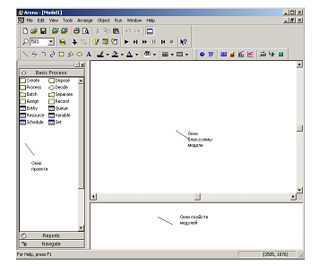
Рис.
1.3. Среда моделирования Arena
Окно
приложения разделено на три области:
1)
Окно рабочего поля модели, в котором
описывается логика модели с использованием
схемных (графических) модулей. Окно
рабочего поля представляет графику
модели, включая блок-схему процесса,
анимацию и другие элементы.
2)
Окно свойств модулей, в котором
отображаются свойства всех модулей
(как модулей данных, так и схемных),
имеющихся и используемых в модели.
3)
Окно проекта – это навигатор системы,
в котором отображается рабочая панель
со всеми модулями и другие доступные и
открытые панели.
Окно
проекта включает в себя несколько
панелей:
1)
Basic Process Panel (панель основных процессов)
– содержит модули, которые используются
для моделирования основной логики
системы.
2)
Advanced Process Panel (панель усовершенствованных
процессов) – содержит дополнительные
модули для создания моделей со сложной
логикой процесса.
3)
Advanced Transfer Panel (панель перемещения) –
содержит специально разработанные
блоки для моделирования процесса
перемещения объектов с помощью
транспортера или конвейера.
4)
Reports (панель отчетов) – панель сообщений:
содержит сообщения, которые отображают
результаты имитационного моделирования.
5)
Navigate (панель навигации) – панель
управления позволяет отображать все
виды модели, включая управление через
иерархические подмодели.
Таким
образом, для того чтобы разрабатывать
имитационные модеи с использованием
ПП Arena, необходимо изучить 3 основные
панели:
Basic
Process Panel, Advanced Process Panel и
Advanced Transfer Panel. Каждая
из этих панелей состоит из двух типов
модулей: схемных модулей (Flowchart Modules) и
модулей данных (Data Modules).
Рассмотрим
более подробно состав каждой панели,
свойства и назначение каждого модуля.
1.4. Basic Process Panel (панель основных процессов)
1.4.1. Схемные модули
Модуль
«Create» является отправной точкой для
сущностей в имитационной модели. Сущности
– это индивидуальные элементы,
обрабатываемые. Создание сущностей
модулем происходит по расписанию или
же, основываясь на значении времени
между прибытиями сущности в модель.
Покидая модуль, сущности начинают
обрабатываться в системе. Тип создаваемых
сущностей определяется в этом модуле.
Применение:
прибытие различных документов в сфере
бизнеса (например: заказы, чеки,
документация); прибытие клиентов в сфере
обслуживания (например: в ресторан, в
магазин); начало изготовления продукции
на производственной линии. Параметры
модуля Create приведены в табл.1.3.
Таблица
1.3
Параметры
модуля Create
|
Параметры |
Описание |
|
Name |
Уникальное |
|
Entity |
Название |
|
Type |
Способ |
Продолжение
табл.1.3
|
Value |
Определяет |
|
Schedule |
Имя |
|
Expression |
Этот |
|
Units |
Единицы |
|
Entities |
Количество |
|
Max |
Максимальное |
|
First Creation |
Время, |
Модуль
«Process» является основным модулем процесса
обработки сущностей в имитационной
модели. В модуле имеются опции использования
ресурсов, т. е., как и при любой обработке,
захватываются какие-то ресурсы. Кроме
стандартного модуля Process, можно
использовать подмодель, придавая ей
особую, определенную пользователем,
иерархическую логическую схему. В модуле
можно также задавать добавочные
стоимостные и временные характеристики
процесса обработки сущности.
Наиболее
частое применение модуля Process: проверка
документов; выполнение заказов;
обслуживание клиентов; обработка
деталей. В табл.1.4 приведены параметры
модуля Process.
Таблица
1.4
Параметры
модуля Process
|
Параметры |
Описание |
|
Name |
Уникальное |
|
Type |
Определяет |
Продолжение табл.
1.4
|
Action |
Тип |
|
Priority |
Значение |
|
Resources |
Определяет |
|
Delay Type |
Тип |
|
Units |
Единицы |
|
Allocation |
Определяет |
Продолжение
табл.1.4
|
Minimum |
Поле, |
|
Maximum |
Поле, |
|
Value |
Поле, |
|
Std |
Параметр, |
|
Expression |
Поле, |
Более
подробно остановимся на параметре
Priority (приоритет) модуля Process. Говоря об
этом параметре, мы должны ввести понятие
«приоритет ресурса» и «приоритет
очереди». Рассмотрим пример и объясним,
что такое «приоритет ресурса».
На
прием к доктору приходят пациенты двух
типов: взрослые и дети. Доктор (наш
ресурс) – один. Он ведет прием и детей,
и взрослых, но детей доктор принимает
около 30 минут, а взрослых около 20 минут,
причем у детей приоритет выше, чем у
взрослых. Каким образом мы можем
реализовать это с помощью модуля Process?
Во-первых, параметр Action этого модуля
должен быть установлен Seize Delay Release для
назначения ресурса, т. е. когда сущность
«пациент» зайдет в модуль, то она захватит
ресурс «доктор» на определенное время.
Во-вторых, у нас по условию время
обслуживания пациентов различное; таким
образом, мы процесс обслуживания
пациентов доктором смоделируем в виде
двух блоков Process с разными временными
задержками (в 30 и 20 минут), но одним и тем
же ресурсом «док-тор». В-третьих, чтобы
установить приоритет у детей выше, мы
в параметре Priority в том процессе, где
время обслуживания 30 минут, т. е.
обслуживание детей, установим приоритет
– High, а во втором процессе – Low или
Medium. Таким образом, когда у нас будут
приходить сущности «дети», они будут
иметь наивысший приоритет в обслуживании.
Рассмотрение понятия «приоритет очереди»
будет приведено ниже (см. модуль данных
очередь Queue).
Модуль
«Decide» позволяет описать и задать логику
модели, учитывая принятие решений. Он
включает опции принятия решений,
основанных на условии By Condition (например,
если тип сущности Car) или основанных на
вероятности By Chance (например, 75 % – true, а
25 % – false). Условия могут быть основаны
на значении атрибута Attribute, значении
переменной Variable, типе сущности Entity Type
или основанные на выражении Expression.
Если
поставленное условие выполняется, то
сущности будут покидать модуль через
ветку True, иначе – по ветке False. Данный
модуль позволяет выполнять проверку
не только одного условия, но и нескольких.
Это достигается с помощью свойства Type
→ N-way
by
Chance/by
Condition.
В зависимости от условия сущность идет
по нужной ветке. Таким образом, по ветке
True у модуля может быть любое количество
выходов (по ветке False – всегда один
выход).
Применение:
разделение дел на срочные дела и
несрочные; перенаправление недоделанных
или сделанных неправильно работ на
доработку. Параметры модуля Decide приведены
в табл.1.5.
Таблица
1.5
Параметры
модуля Decide
|
Параметры |
Описание |
|
Name |
Уникальное |
Продолжение
табл.1.5
|
Type |
Тип |
|
Percent |
Значение, |
|
If |
Тип |
|
Named |
Имя |
|
Is |
Математический |
|
Value |
Значение, |
Модуль
«Batch» отвечает за механизм группировки
сущностей в имитационной модели.
Группировка может быть постоянной или
временной. Временно сгруппированные
комплекты сущностей позднее могут быть
разъединены с помощью модуля Separate.
Комплекты могут состоять из любого
числа входящих сущностей, определенного
пользователем, или же сущности могут
объединяться в комплект в зависимости
от атрибута сущности. Временные и
стоимостные характеристики выходящей
сущности, представляющей комплект,
будут равны сумме характеристик вошедших
в группу сущностей.
Сущности
прибывают в модуль, становятся в очередь
и остаются там до тех пор, пока в модуле
не будет набрано заданное количество
сущностей. Когда соберется нужное число
сущностей, создается сущность,
представляющая комплект.
Применение:
собрать необходимое количество данных,
прежде чем начинать их обработку; собрать
ранее разделенные копии одной формы;
соединить пациента и его больничную
карту приема к врачу.
В
табл.1.6 приведены параметры модуля Batch
Таблица
1.6
Параметры
модуля Batch
|
Параметры |
Описание |
|
Name |
Уникальное |
|
Type |
Способ |
|
Batch |
Число |
|
Rule |
Определяет, |
|
Attribute |
Имя |
Модуль
Separate может использоваться в двух
возможных вариантах:
1)
Для создания копий входящих сущностей.
Если модуль создает копии сущностей,
то пользователь может задать количество
дубликатов сущности. У дублированной
сущности значения атрибута, а также
анимационная картинка такие же, как и
оригинала. Оригинальная сущность также
покидает модуль.
2)
Для разделения ранее сгруппированных
сущностей. Правило для разделения
стоимостных и временных характеристик
копий сущностей и разделенных сущностей
определяется пользователем. Когда
временно сгруппированные сущности
прибывают в модуль, они раскладываются
на составные сущности. Сущности покидают
модуль в той же последовательности, в
которой они добавлялись в комплект.
Применение:
разъединение ранее сгруппированных
комплектов документов; для параллельной
обработки счетов и документов; для
параллельной обработки счетов и
документов по одному заказу. В табл.1.7
приведены параметры модуля Separate.
Таблица
1.7
Параметры
модуля Separate
|
Параметры |
Описание |
|
Name |
Уникальное |
|
# |
Количество |
|
Type |
Способ |
|
Allocation Rule |
Метод Take Take |
Модуль
Assign предназначен для задания нового
значения переменной, атрибуту сущности,
типу сущности, анимационной картинке
сущности или другой переменной в системе.
В
одном модуле можно сделать только
любое количество назначений: сменить
тип сущности, ее картинку, задать любое
количество переменных и т. д.
Пример
применения модуля Assign: установление
приоритета для клиентов; присвоение
номера вышедшему приказу. Параметры
модуля Assign приведены в табл.1.8.
Таблица
1.8
Параметры
модуля Assign
|
Параметры |
Описание |
|
Name |
Уникальное |
|
Type |
Тип |
|
Variable |
Имя |
|
Attribute |
Имя |
|
Entity |
Новый |
|
Entity |
Новая |
|
New |
Присваиваемое |
Модуль Record
предназначен для сбора статистики в
имитационной модели. Модуль может
собирать различные типы статистики,
включая
время
между выходами сущностей из модуля,
статистику сущности (время цикла,
стоимость), статистику за период
времени (период времени от заданной
точки до текущего момента). Также
доступен количественный тип статистики.
Частое
применение модуля: подсчитать, какое
количество заказов было выполнено с
опозданием; подсчитать количество
работы, совершаемое за один час.
Параметры
модуля
Record
приведены в табл.1.9.
Таблица
1.9
Параметры
модуля
Record
|
Параметры |
Описание |
|
Name |
Уникальное |
|
Type |
Определяет |
|
Attribute Name |
Имя |
|
Value |
Значение, |
Этот
модуль является выходной точкой из
имитационной модели. Статистика о
сущности может собираться до того
момента, пока она не выйдет из системы.
Модуль
Dispose является выходной точкой из
имитационной модели. Применение:
окончание бизнес-процесса; клиенты
покидают отдел. В табл.1.10 приведены
параметры
модуля Dispose.
Таблица
1.10
Параметры
модуля Dispose
|
Параметры |
Описание |
|
Name |
Уникальное |
|
Record Statistics |
Определяет, |
1.4.2.
Модули данных
Все
модули данных в навигаторе панелей
имеют одинаковый вид, т. к. они не
отображаются физически в блок-схеме
модели, в связи с этим их изображение
не приводится. Также мы не будем
рассматривать стоимостные параметры
модулей, т. к. они не влияют на логику
модели.
Модуль
Entity определяет тип сущности и ее
анимационную картинку в имитационном
процессе, также определяет стоимостную
информацию. Для каждого источника
должен быть определен тип сущности,
который он генерирует.
Применение
модуля Entity: документы (факсы, письма,
отчеты и т. д.); люди в моделях больницы
или магазина.
В
табл.1.11 приведены параметры
модуля Entity.
Таблица
1.11
Параметры
модуля Entity
|
Параметры |
Описание |
|
Entity |
Название |
|
Initial |
Графическое |
Модуль
данных Queue предназначен для изменения
правила расстановки сущностей в
очереди, т. е. задается правило
обслуживания сущности в процессе. По
умолчанию тип очереди First in First out.
Применение:
стопка документов, ожидающих освобождения
ресурса; место для собирания частей,
ожидающих упаковки (группировки). В
табл.1.12 приведены параметры
модуля Queue.
Таблица
1.12
Параметры
модуля Queue
|
Параметры |
Описание |
|
Name |
Уникальное |
|
Attribute Name |
Имя |
Продолжение
табл.1.12
|
Type |
Правило |
Более
подробно хотелось бы остановиться на
параметре Type, т. к. именно с помощью него
можно определить, что такое «приоритет
очереди» и как его необходимо задавать.
Рассмотрим несколько изменный наш
пример.
На
прием к доктору приходят пациенты
двух типов: взрослые и дети. Доктор
(наш ресурс) – один. Он ведет прием и
детей, и взрослых, причем время приема
одинаково (около 30 минут), но у детей
приоритет при обслуживании выше, чем у
взрослых.
Каким
образом мы это можем реализовать?
Во-первых, в модуле Process задается ресурс
«доктор»; с помощью параметра Action,
который устанавливаем Seize Delay Release для
назначения ресурса. Таким образом, когда
сущность «пациент» зайдет в модуль
процесс, то она захватит ресурс «доктор»
на определенное время (около 30 минут).
Во-вторых, у нас по условию время
обслуживания пациентов одинаковое,
таким образом, мы процесс обслуживания
пациентов доктором смоде-лируем в
виде одного блока Process, с временной
задержкой в 30 минут.
Но
здесь возникает вопрос: каким образом
задать приоритет? В данном случаем, мы
рассматриваем ситуацию, когда ресурс
задан в одном блоке, т. е. нет смысла
менять параметр Priority модуля Process. В этом
случае, возникает ситуация, когда
приоритет не ресурса, а приоритет
очереди. И задается он в модуле Queue.
Необходимо выбрать, у какого типа
сущности он выше. Это производится
с помощью параметра Type:
Lowest
Attribute Value – первый выйдет из очереди
тот, значение атрибута у которого низшее,
или Highest Attribute Value – первый выйдет из
очереди тот, значение атрибута у которого
наивысшее. Таким образом, когда у нас
будут приходить сущности «дети», они
будут иметь наивысший приоритет в
обслуживании.
Модуль
Resource предназначен для определения
ресурсов и их свойств в имитационном
процессе; кроме того, модуль включает
в себя стоимостную информацию о ресурсах
и вместимость ресурсов. Ресурсы могут
иметь фиксированную вместимость или
же основанную на расписании.
У
ресурсов с фиксированной вместимостью
в течение имитационного процесса
вместимость изменяться не может. Ресурс
должен быть связан с каким-либо процессом.
Применение:
люди (клерки, продавцы, бухгалтеры,
рабочие и т. д.); оборудование (телефонная
линия, станок, компьютер). Параметры
модуля Resource приведены в табл.1.13.
Таблица
1.13
Параметры
модуля Resource
|
Параметры |
Описание |
|
Name |
Имя |
|
Type |
Метод, |
|
Capacity |
Число |
|
Schedule Name |
Имя |
Продолжение табл.
1.13
|
Busy |
Почасовая |
|
Idle |
Стоимость |
|
Per |
Стоимость |
Модуль
Schedule может использоваться вместе с
модулем Resource для определения вместимости
ресурса и с модулем Create – для задания
расписания прибытия сущностей.
Применение:
расписание работы персонала с перерывами
на обед; значение покупателей, прибывающих
в супермаркет.
Параметры
модуля Schedule приведены в табл.1.14.
Таблица
1.14
Параметры
модуля Schedule
|
Параметры |
Описание |
|
Name |
Название |
|
Type |
Тип |
|
Time |
Масштаб |
Модуль
данных Set,
который описывает группу ресурсов,
использующихся в модуле Process.
В
группе могут находиться несколько
ресурсов. Модуль Set
автоматически
создает ресурсы, вместимость которых
по умолчанию равна 1, и без всякой
стоимостной информации. Следовательно,
если для ресурсов, входящих в группу,
не нужно стоимостной информации и
вместимость более 1, то можно обойтись
созданием только модуля Set.
Возможно
применение модуля для организации
работы группы работников, например по
очереди. Параметры
модуля Set приведены в табл.1.15.
Таблица
1.15
Параметры
модуля Set
|
Параметры |
Описание |
|
Name |
Название |
|
Members |
Перечисляет |
|
Resource Name |
Названия |
Модуль
Variable определяет
значение переменных. Переменные,
относящиеся к модулю Decide
или
Assign,
могут
использоваться в выражениях. Если
переменная не описана в этом модуле, то
ее первоначальное значение равно 0.
Применение:
число документов обрабатываемых в час;
присвоение серийного номера для
идентификации продукции.
В
табл.1.16 приведены параметры
модуля Variable.
Таблица
1.16
Параметры
модуля Variable
|
Параметры |
Описание |
|
Name |
Имя |
|
Initial |
Первоначальное |
|
Rows |
Число |
|
Columns |
Число |
|
Clear |
Определяет |
|
Statistics |
Определяет, |
Соседние файлы в предмете [НЕСОРТИРОВАННОЕ]
- #
- #
- #
- #
- #
- #
- #
- #
- #
- #
- #