Руководства пользователя
- Руководства пользователя
- Декларация соответствия
Версия —
15.18 MB
Windows_7_Setup_Guide_DVD
Версия E11428
1.7 MB
H110M-R User’s manual (English)
Версия DT162
3.81 MB
Intel 100 Series Ai Suite3 Manual(Traditional Chinese)
Версия DS162
2.64 MB
Intel 100 Series Ai Suite3 Manual(Spanish)
Версия DR162
2.15 MB
Intel 100 Series Ai Suite3 Manual(Russian)
Версия DK162
2.73 MB
Intel 100 Series Ai Suite3 Manual(Korean)
Версия DJ162
3.69 MB
Intel 100 Series Ai Suite3 Manual(Japanese)
Версия DG162
2.11 MB
Intel 100 Series Ai Suite3 Manual(German)
Версия DF162
3.54 MB
Intel 100 Series Ai Suite3 Manual(French)
Версия DE162
2.74 MB
Intel 100 Series Ai Suite3 Manual(English)
- Manuals
- Brands
- Asus Manuals
- Motherboard
- H110M-R
- Manual
-
Contents
-
Table of Contents
-
Bookmarks
Quick Links
Related Manuals for Asus H110M-R
Summary of Contents for Asus H110M-R
-
Page 1
H110M-R… -
Page 2
Product warranty or service will not be extended if: (1) the product is repaired, modified or altered, unless such repair, modification of alteration is authorized in writing by ASUS; or (2) the serial number of the product is defaced or missing. -
Page 3: Table Of Contents
Contents Safety information ………………iv About this guide ………………iv Package contents ………………vi H110M-R specifications summary …………vi Chapter 1: Product introduction Motherboard overview …………….1-1 Central Processing Unit (CPU) …………..1-7 System memory ………………1-8 Intel SBB support ………………. 1-9 ®…
-
Page 4: Safety Information
Safety information Electrical safety • To prevent electrical shock hazard, disconnect the power cable from the electrical outlet before relocating the system. • When adding or removing devices to or from the system, ensure that the power cables for the devices are unplugged before the signal cables are connected. If possible, disconnect all power cables from the existing system before you add a device.
-
Page 5
Refer to the following sources for additional information and for product and software updates. ASUS websites The ASUS website provides updated information on ASUS hardware and software products. Refer to the ASUS contact information. Optional documentation Your product package may include optional documentation, such as warranty flyers, that may have been added by your dealer. -
Page 6: Package Contents
Extreme Memory Profile (XMP) Memory * Refer to www.asus.com for the latest Memory QVL (Qualified Vendors List). ** Due to Intel® chipset limitation, DDR4 2133 MHz and higher memory modules on XMP mode will run at the maximum transfer rate of DDR4 2133 Mhz.
-
Page 7
— ASUS DIGI+ VRM — 3+1 Phase digital power design — ASUS DRAM Overcurrent Protection — Enhanced DRAM Overcurrent Protection — ASUS Stainless Steel Back I/O — 3X more durable corrosion-resistant coating Superb Performance UEFI BIOS — Most advanced options with fast response time… -
Page 8
7 (32-bit / 64-bit) * ® * Please refer to ASUS official website and download “Windows® 7 installation guide” and “ASUS EZ installer” to install Windows® 7. uATX form factor: 8.3 in. x 7.1 in. (21.08 cm x 18.03 cm) Form factor Specifications are subject to change without notice. -
Page 9: Motherboard Overview
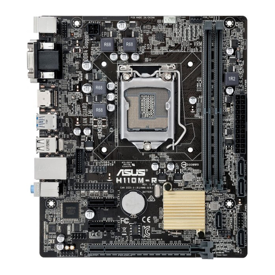
CPU_FAN KBMS CHA_FAN DIGI +VRM ATX12V 2168 Place this side towards HDMI the rear of the chassis LGA1151 USB3_34 USB78 USB3_12 Realtek 8111H USB910 LAN_USB56 H110M-R AUDIO PCIEX1_1 Intel ® Super H110 PCIEX1_2 128Mb BIOS AAFP PCIEX16 Scan the QR code to get the detailed pin definitions. ASUS H110M-R…
-
Page 10
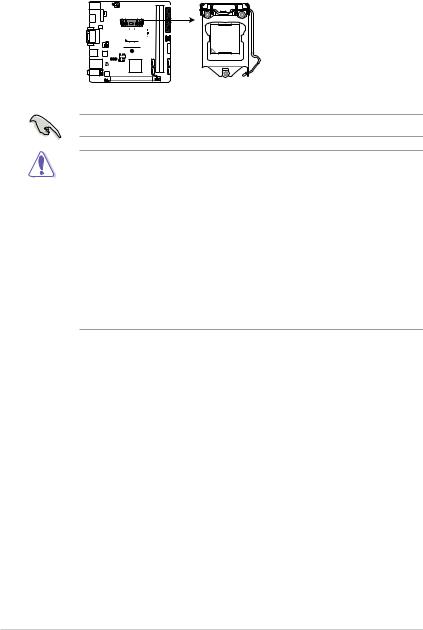
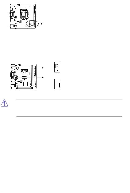
Correctly orient the ATX power supply plugs into these connectors and push down firmly until the connectors completely fit. • For a fully configured system, we recommend that you use a power supply unit (PSU) that complies with ATX 12 V Specification 2.0 (or later version) and provides a minimum power of 350 W. • If you are uncertain about the minimum power supply requirement for your system, refer to the Recommended Power Supply Wattage Calculator at http://support.asus.com/PowerSupplyCalculator/ PSCalculator.aspx?SLanguage=en-us for details. Intel LGA1151 CPU socket ® Install Intel LGA1151 CPU into this surface mount LGA1151 socket, which is ® designed for 6th Generation Intel Core™ i7 / i5 / i3, Pentium , and Celeron ®… -
Page 11
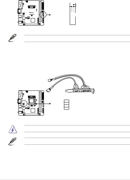
Connect one end of the chassis intrusion sensor or switch cable to this header. The chassis intrusion sensor or switch sends a high-level signal to this header when a chassis component is removed or replaced. The signal is then generated as a chassis intrusion event. By default, the pin labeled “Chassis Signal” and “Ground” are shorted with a jumper cap. Remove the jumper caps only when you intend to use the chassis intrusion detection feature. Speaker connector (4-pin SPEAKER) This 4-pin connector is for the chassis-mounted system warning speaker. The speaker allows you to hear system beeps and warnings. Clear RTC RAM (2-pin CLRTC) CLRTC This header allows you to clear the CMOS RTC RAM data of the system setup information such as date, time, and system passwords. To erase the RTC RAM: PIN 1 Turn OFF the computer and unplug the power cord. Use a metal object such as a screwdriver to short the two pins. Plug the power cord and turn ON the computer. Hold down the <Del> key during the boot process and enter BIOS setup to re-enter data. If the steps above do not help, remove the onboard battery and short the two pins again to clear the CMOS RTC RAM data. After clearing the CMOS, reinstall the battery. ASUS H110M-R… -
Page 12
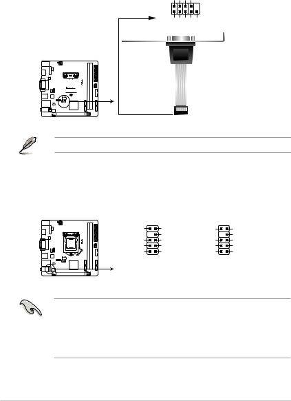
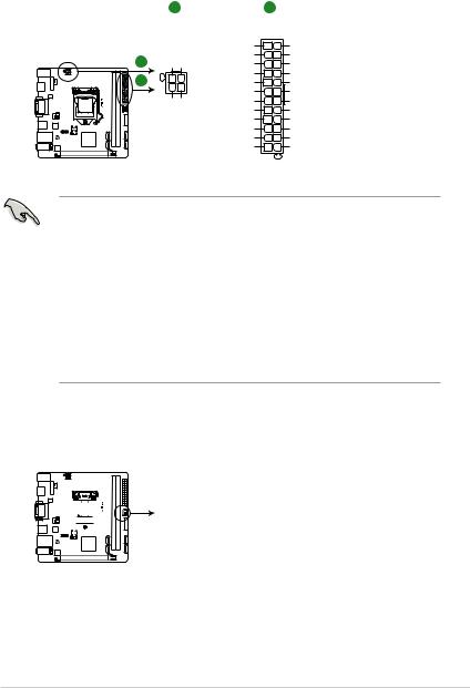
Front panel audio connector (10-1 pin AAFP) This connector is for a chassis-mounted front panel audio I/O module that supports either HD Audio or legacy AC`97 audio standard. Connect one end of the front panel audio I/O module cable to this connector. • We recommend that you connect a high-definition front panel audio module to this connector to avail of the motherboard’s high-definition audio capability. • If you want to connect a high-definition front panel audio module to this connector, set the Front Panel Type item in the BIOS setup to [HD Audio]. If you want to connect an AC’97 front panel audio module to this connector, set the item to [AC97]. By default, this connector is set to [HD Audio]. Serial port connector (10-1 pin COM) Connect the serial port module cable to this connector, then install the module to a slot opening at the back of the system chassis. PCI Express 3.0/2.0 x16 slot This motherboard supports PCI Express 3.0/2.0 x16 graphic cards complying with the PCI Express specifications. PCI Express 2.0 x1 slots This motherboard has two PCI Express 2.0 x1 slots that support PCI Express x1 network cards, SCSI cards, and other cards that comply with the PCI Express specifications. -
Page 13
Video Graphics Adapter (VGA) port. This 15-pin port is for a VGA monitor or other VGA-compatible devices. Activity Link Speed LAN (RJ-45) port. This port allows Gigabit connection to a Local Area Network (LAN) through a network hub. LAN port LAN port LED indications Activity/Link LED Speed LED Status Description Status Description No link 10Mbps connection Orange Linked ORANGE 100Mbps connection Orange (Blinking) Data activity GREEN 1Gbps connection Orange (Blinking Ready to wake up then steady) from S5 mode ASUS H110M-R… -
Page 14
Line In port (light blue). This port connects to the tape, CD, DVD player, or other audio sources. Line Out port (lime). This port connects to a headphone or a speaker. In the 4.1, 5.1 and 7.1-channel configurations, the function of this port becomes Front Speaker Out. Microphone port (pink). This port connects to a microphone. Refer to the audio configuration table for the function of the audio ports in 2.1, 4.1, 5.1, or 7.1-channel configuration. Audio 2.1, 4.1, 5.1, or 7.1-channel configuration Headset Port 4.1-channel 5.1-channel 7.1-channel 2.1-channel Light Blue (Rear panel) Line In Rear Speaker Out Rear Speaker Out Rear Speaker Out Lime (Rear panel) Line Out Front Speaker Out Front Speaker Out Front Speaker Out Pink (Rear panel) Mic In Mic In Bass/Center… -
Page 15: Central Processing Unit (Cpu)
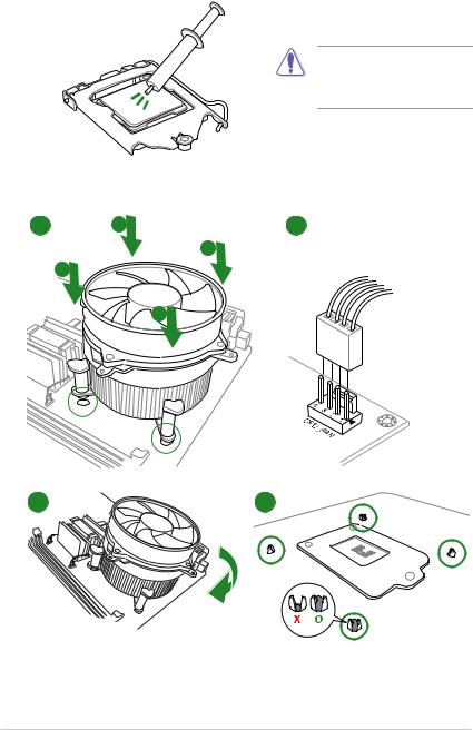
Central Processing Unit (CPU) This motherboard comes with a surface mount LGA1151 socket designed for 6th Generation Intel Core™ i7 / i5 / i3, Pentium , and ® ® Celeron processors. ® Unplug all power cables before installing the CPU. • Ensure that you install the correct CPU designed for the LGA1151 socket only. DO NOT install a CPU designed for LGA1150, LGA1155 and LGA1156 sockets on the LGA1151 socket. • Upon purchase of the motherboard, ensure that the PnP cap is on the socket and the socket contacts are not bent. Contact your retailer immediately if the PnP cap is missing, or if you see any damage to the PnP cap/socket contacts/motherboard components. • Keep the cap after installing the motherboard. ASUS will process Return Merchandise Authorization (RMA) requests only if the motherboard comes with the cap on the LGA1151 socket. • The product warranty does not cover damage to the socket contacts resulting from incorrect CPU installation/removal, or misplacement/loss/incorrect removal of the PnP cap. Installing the CPU Apply the Thermal Interface Material to the CPU heatsink and CPU before you install the heatsink and fan if necessary. ASUS H110M-R…
-
Page 16: System Memory
(D/C) from the same vendor. Check with the vendor to get the correct memory modules. • According to Intel CPU spec, DIMM voltage below 1.35V is recommended to protect ® the CPU. • Due to the memory address limitation on 32-bit Windows OS, when you install 4GB ® or more memory on the motherboard, the actual usable memory for the OS can be about 3GB or less. For effective use of memory, we recommend that you do any of the following: Use a maximum of 3 GB system memory if you are using a 32-bit Windows OS. ® I nstall a 64-bit Windows OS if you want to install 4GB or more on the ® motherboard. F or more details, refer to the Microsoft support site at http://support.microsoft. ® com/kb/929605/en-us. Visit the ASUS website at www.asus.com for the latest QVL. Installing a DIMM To remove a DIMM Chapter 1: Product introduction…
-
Page 17: Intel ® Sbb Support
® the-box value for small business. Intel SBB requires MEI driver (AMT host software kit) to be installed and running. ® Platform requirements: • Windows 7 (32/64-bit) / Windows 8.1 (64-bit) / Windows 10 (64-bit) ® ® ® • PCH with 6th-generation Intel Core™ CPU (100 Series platforms) with 2MB Intel ® ® Management Engine 11.0 firmware installed CPU and chipsets requirements: • Intel Core™ i3 / i5 /i7 with one of these chipsets: H110, B150, H170, Q170 ® Other requirements: • Local Administrator rights on the target machine • Visit the ASUS website at www.asus.com for the latest CPU QVL (Qualified Vendors List). • Uninstall SBA4.0 before you install and upgrade to the latest version. ASUS H110M-R…
-
Page 18: Chapter 2: Bios Information
To enter BIOS Setup after POST: • Press <Ctrl>+<Alt>+<Del> simultaneously. • Press the reset button on the system chassis. • Press the power button to turn the system off then back on. Do this option only if you failed to enter BIOS Setup using the first two options. Using the power button, reset button, or the <Ctrl>+<Alt>+<Del> keys to force reset from a running operating system can cause damage to your data or system. We recommend you always shut down the system properly from the operating system. • The BIOS setup screens shown in this section are for reference purposes only, and may not exactly match what you see on your screen. • Visit the ASUS website at www.asus.com to download the latest BIOS file for this motherboard. • If the system becomes unstable after changing any BIOS setting, load the default settings to ensure system compatibility and stability. Select the Load Optimized Defaults item under the Exit menu or press hotkey F5. • If the system fails to boot after changing any BIOS setting, try to clear the CMOS and reset the motherboard to the default value. See section Motherboard overview for information on how to erase the RTC RAM. BIOS menu screen The BIOS setup program can be used under two modes: EZ Mode and Advanced Mode. Press <F7> to change between the two modes. ASUS H110M-R…
-
Page 19: Ez Mode
EZ Mode By default, the EZ Mode screen appears when you enter the BIOS setup program. The EZ Mode provides you an overview of the basic system information, and allows you to select the display language, system performance mode, fan profile and boot device priority. To access the Advanced Mode, click Advanced Mode(F7) or press <F7>. The default screen for entering the BIOS setup program can be changed. Refer to the Setup Mode item in section 2.8 Boot menu for details. Displays the system properties of the selected mode. Click <Enter> to Displays the CPU/motherboard switch EZ System Tuning modes temperature, CPU voltage output, Selects the display CPU/chassis fan speed, and SATA language of the BIOS information setup program…
-
Page 20: Advanced Mode
Q-Fan control Language Hot Keys Menu bar Configuration fields Scroll bar Last modified Sub-menu item General help settings Menu items Goes back to EZ Mode Search on FAQs Popup window Displays the CPU temperature, CPU and memory voltage output ASUS H110M-R…
-
Page 21: Exit Menu
Search on FAQ Move your mouse over this button to show a QR code. Scan this QR code with your mobile device to connect to the ASUS BIOS FAQ web page. You can also scan the QR code below. Exit menu The Exit menu items allow you to load the optimal default values for the BIOS items, and save or discard your changes to the BIOS items. Load Optimized Defaults This option allows you to load the default values for each of the parameters on the Setup menus. When you select this option or if you press <F5>, a confirmation window appears. Select OK to load the default values. Save Changes & Reset Once you are finished making your selections, choose this option from the Exit menu to ensure the values you selected are saved. When you select this option or if you press <F10>, a confirmation window appears. Select OK to save changes and exit. Discard Changes and Exit This option allows you to exit the Setup program without saving your changes. When you select this option or if you press <Esc>, a confirmation window appears. Select OK to discard changes and exit. Launch EFI Shell from USB drives This option allows you to attempt to launch the EFI Shell application (shellx64.efi) from one of the available USB devices. Chapter 2: Getting started…
-
Page 22: Appendices
Cet appareil est conforme aux normes CNR exemptes de licence d’Industrie Canada. Le fonctionnement est soumis aux deux conditions suivantes : (1) cet appareil ne doit pas provoquer d’interférences et (2) cet appareil doit accepter toute interférence, y compris celles susceptibles de provoquer un fonctionnement non souhaité de l’appareil. ASUS H110M-R…
-
Page 23
ASUS Recycling/Takeback Services ASUS recycling and takeback programs come from our commitment to the highest standards for protecting our environment. We believe in providing solutions for you to be able to responsibly recycle our products, batteries, other components as well as the packaging materials. -
Page 24
CE. das Diretivas da CE. Para mais detalhes, consulte a Declaração de Компания ASUS заявляет, что это устройство соответствует основным Conformidade CE. требованиям и другим соответствующим условиям европейских директив. Подробную информацию, пожалуйста, смотрите в декларации… -
Page 25: Asus Contact Information
+1-510-739-3777 +1-510-608-4555 Web site http://www.asus.com/us/ Technical Support Support fax +1-812-284-0883 Telephone +1-812-282-2787 Online support http://qr.asus.com/techserv ASUS COMPUTER GmbH (Germany and Austria) Address Harkort Str. 21-23, D-40880 Ratingen, Germany +49-2102-959931 Web site http://www.asus.com/de Online contact http://eu-rma.asus.com/sales Technical Support Telephone +49-2102-5789555 Support Fax…
-
Page 26
ASUS H110M-R…
|
Код: 116626 Извините, товара сейчас нет в наличии
Бесплатная доставка
Извините, товара сейчас нет в наличии Сравнить Новости интернет-магазина «Лаукар»:28.03.2023 22.02.2023 13.02.2023 Дополнительная информация в категории Материнская плата:Таблица Авторизованных сервисных центров по брендам. Описание Инструкция Отзывы (0) В интернет-магазине бытовой техники «Лаукар» Вы можете скачать инструкцию к товару Материнская плата Asus H110M-R/C/SI совершенно бесплатно. Все инструкции, представленные на сайте интернет-магазина бытовой техники «Лаукар», предоставляются производителем товара. Для того чтобы скачать инструкцию, Вам необходимо нажать на ссылку «скачать инструкцию», расположенную ниже, а в случае, если ссылки нет, Скачать инструкцию Смотреть инструкцию
Фирма-производитель оставляет за собой право на внесение изменений в конструкцию, дизайн и комплектацию товара: Материнская плата Asus H110M-R/C/SI. Пожалуйста, сверяйте информацию о товаре с информацией на |


24 мая 2016 г.
- Производитель
- Asus
- Модель
- H110M-R
- Операционная система
-
- Windows 10
- Windows 8.1
- Windows 8
- Windows 7
- Тип файла
-
- Инструкция
- Версия
-
E11428
32-bit
64-bit
Просмотреть содержимое архива
Вы нашли то, что искали?
Полезно
0 %
0
Commentary
Ваше имя
 Loading…
![]()
E10783
First Edition
August 2015
Copyright © 2015 ASUSTeK COMPUTER INC. All Rights Reserved.
No part of this manual, including the products and software described in it, may be reproduced, transmitted, transcribed, stored in a retrieval system, or translated into any language in any form or by any means, except documentation kept by the purchaser for backup purposes, without the express written permission of ASUSTeK COMPUTER INC. (“ASUS”).
Product warranty or service will not be extended if: (1) the product is repaired, modified or altered, unless such repair, modification of alteration is authorized in writing by ASUS; or (2) the serial number of the product is defaced or missing.
ASUS PROVIDES THIS MANUAL “AS IS” WITHOUT WARRANTY OF ANY KIND, EITHER EXPRESS OR IMPLIED, INCLUDING BUT NOT LIMITED TO THE IMPLIED WARRANTIES OR CONDITIONS OF MERCHANTABILITY OR FITNESS FOR A PARTICULAR PURPOSE. IN NO EVENT SHALL ASUS, ITS DIRECTORS, OFFICERS, EMPLOYEES OR AGENTS BE LIABLE FOR ANY INDIRECT, SPECIAL, INCIDENTAL, OR CONSEQUENTIAL DAMAGES (INCLUDING DAMAGES FOR LOSS OF PROFITS, LOSS OF BUSINESS, LOSS OF USE OR DATA, INTERRUPTION OF BUSINESS AND THE LIKE), EVEN IF ASUS HAS BEEN ADVISED OF THE POSSIBILITY OF SUCH DAMAGES ARISING FROM ANY DEFECT OR ERROR IN THIS MANUAL OR PRODUCT.
SPECIFICATIONS AND INFORMATION CONTAINED IN THIS MANUAL ARE FURNISHED FOR INFORMATIONAL USE ONLY, AND ARE SUBJECT TO CHANGE AT ANY TIME WITHOUT NOTICE, AND SHOULD NOT BE CONSTRUED AS A COMMITMENT BY ASUS. ASUS ASSUMES NO RESPONSIBILITY OR LIABILITY FOR ANY ERRORS OR INACCURACIES THAT MAY APPEAR IN THIS MANUAL, INCLUDING THE PRODUCTS AND SOFTWARE DESCRIBED IN IT.
Products and corporate names appearing in this manual may or may not be registered trademarks or copyrights of their respective companies, and are used only for identification or explanation and to the owners’ benefit, without intent to infringe.
Offer to Provide Source Code of Certain Software
This product contains copyrighted software that is licensed under the General Public License (“GPL”), under the Lesser General Public License Version (“LGPL”) and/or other Free Open Source Software Licenses. Such software in this product is distributed without any warranty to the extent permitted by the applicable law. Copies of these licenses are included in this product.
Where the applicable license entitles you to the source code of such software and/or other additional data, you may obtain it for a period of three years after our last shipment of the product, either
(1)for free by downloading it from http://support.asus.com/download
or
(2)for the cost of reproduction and shipment, which is dependent on the preferred carrier and the location where you want to have it shipped to, by sending a request to:
ASUSTeK Computer Inc.
Legal Compliance Dept.
15 Li Te Rd.,
Beitou, Taipei 112
Taiwan
In your request please provide the name, model number and version, as stated in the About Box of the product for which you wish to obtain the corresponding source code and your contact details so that we can coordinate the terms and cost of shipment with you.
The source code will be distributed WITHOUT ANY WARRANTY and licensed under the same license as the corresponding binary/object code.
This offer is valid to anyone in receipt of this information.
ASUSTeK is eager to duly provide complete source code as required under various Free Open Source Software licenses. If however you encounter any problems in obtaining the full corresponding source code we would be much obliged if you give us a notification to the email address gpl@asus.com, stating the product and describing the problem (please DO NOT send large attachments such as source code archives, etc. to this email address).
ii

Contents
|
Safety information ………………………………………………………………………….. |
iv |
|
About this guide …………………………………………………………………………….. |
iv |
|
Package contents …………………………………………………………………………… |
vi |
|
H110I-PLUS D3 specifications summary………………………………………….. |
vi |
|
Chapter 1: |
Product introduction |
||
|
1.1 |
Before you proceed …………………………………………………………… |
1-1 |
|
|
1.2 |
Motherboard overview……………………………………………………….. |
1-2 |
|
|
1.3 |
Central Processing Unit (CPU) …………………………………………… |
1-4 |
|
|
1.4 |
System memory ………………………………………………………………… |
1-7 |
|
|
1.5 |
Expansion slots……………………………………………………………….. |
1-10 |
|
|
1.6 |
Headers |
…………………………………………………………………………… |
1-11 |
|
1.7 |
Connectors ……………………………………………………………………… |
1-12 |
|
|
1.8 |
Software ………………………………………………………………support |
1-20 |
|
Chapter 2: |
BIOS information |
||
|
2.1 |
Managing and updating your BIOS |
…………………………………….. 2-1 |
|
|
2.2 |
BIOS setup program ………………………………………………………….. |
2-6 |
|
|
2.3 |
My Favorites ……………………………………………………………………. |
2-13 |
|
|
2.4 |
Main menu ………………………………………………………………………. |
2-14 |
|
|
2.5 |
Ai Tweaker menu……………………………………………………………… |
2-16 |
|
|
2.6 |
Advanced menu ………………………………………………………………. |
2-22 |
|
|
2.7 |
Monitor menu ………………………………………………………………….. |
2-29 |
|
|
2.8 |
Boot menu ………………………………………………………………………. |
2-32 |
|
|
2.9 |
Tool menu……………………………………………………………………….. |
2-37 |
|
|
2.10 |
Exit menu………………………………………………………………………… |
2-38 |
|
|
Appendices |
|||
|
Notices…………………………………………………………………………………………. |
A-1 |
||
|
ASUS contact information …………………………………………………………….. |
A-4 |
iii

Safety information
Electrical safety
•To prevent electrical shock hazard, disconnect the power cable from the electrical outlet before relocating the system.
•When adding or removing devices to or from the system, ensure that the power cables for the devices are unplugged before the signal cables are connected. If possible, disconnect all power cables from the existing system before you add a device.
•Before connecting or removing signal cables from the motherboard, ensure that all power cables are unplugged.
•Seek professional assistance before using an adapter or extension cord. These devices could interrupt the grounding circuit.
•Ensure that your power supply is set to the correct voltage in your area. If you are not sure about the voltage of the electrical outlet you are using, contact your local power company.
•If the power supply is broken, do not try to fix it by yourself. Contact a qualified service technician or your retailer.
Operation safety
•Before installing the motherboard and adding components, carefully read all the manuals that came with the package.
•Before using the product, ensure all cables are correctly connected and the power cables are not damaged. If you detect any damage, contact your dealer immediately.
•To avoid short circuits, keep paper clips, screws, and staples away from connectors, slots, sockets and circuitry.
•Avoid dust, humidity, and temperature extremes. Do not place the product in any area where it may be exposed to moisture.
•Place the product on a stable surface.
•If you encounter technical problems with the product, contact a qualified service technician or your retailer.
About this guide
This user guide contains the information you need when installing and configuring the motherboard.
How this guide is organized
This guide contains the following parts:
•Chapter 1: Product introduction
This chapter describes the features of the motherboard and the new technology it supports. It includes descriptions of the switches, jumpers, and connectors on the motherboard.
•Chapter 2: BIOS information
This chapter discusses changing system settings through the BIOS Setup menus. Detailed descriptions for the BIOS parameters are also provided.
iv
Where to find more information
Refer to the following sources for additional information and for product and software updates.
1.ASUS websites
The ASUS website provides updated information on ASUS hardware and software products. Refer to the ASUS contact information.
2.Optional documentation
Your product package may include optional documentation, such as warranty flyers, that may have been added by your dealer. These documents are not part of the standard package.
Conventions used in this guide
To ensure that you perform certain tasks properly, take note of the following symbols used throughout this manual.
DANGER/WARNING: Information to prevent injury to yourself when completing a task.
CAUTION: Information to prevent damage to the components when completing a task
IMPORTANT: Instructions that you MUST follow to complete a task.
NOTE: Tips and additional information to help you complete a task.
Typography
|
Bold text |
Indicates a menu or an item to select. |
|
Italics |
Used to emphasize a word or a phrase. |
|
<Key> |
Keys enclosed in the less-than and greater-than sign |
|
means that you must press the enclosed key. |
|
|
Example: <Enter> means that you must press the Enter or |
|
|
Return key. |
|
|
<Key1> + <Key2> + <Key3> |
If you must press two or more keys simultaneously, the key |
|
names are linked with a plus sign (+). |
v

1.1Before you proceed
Take note of the following precautions before you install motherboard components or change any motherboard settings.
• Unplug the power cord from the wall socket before touching any component.
•Before handling components, use a grounded wrist strap or touch a safely grounded object or a metal object, such as the power supply case, to avoid damaging them due to static electricity.
•Before you install or remove any component, ensure that the ATX power supply is switched off or the power cord is detached from the power supply. Failure to do so may cause severe damage to the motherboard, peripherals, or components.
1.2Motherboard overview
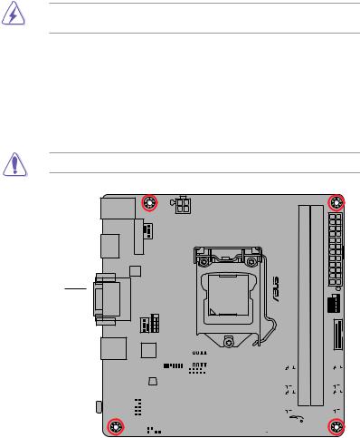
Before you install the motherboard, study the configuration of your chassis to ensure that the motherboard fits.
Unplug the power cord before installing or removing the motherboard. Failure to do so can cause you physical injury and damage to motherboard components.
1.2.1Placement direction
When installing the motherboard, place it into the chassis in the correct orientation. The edge with external ports goes to the rear part of the chassis as indicated in the image.
1.2.2Screw holes
Place four screws into the holes indicated by circles to secure the motherboard to the chassis.
Do not overtighten the screws! Doing so can damage the motherboard.
Place this side towards the rear of the chassis
|
1-2 |
Chapter 1: Product introduction |
1.3Central Processing Unit (CPU)
This motherboard comes with a surface mount LGA1151 socket designed for 6th Generation Intel® Core™ i7 / i5 / i3, Pentium®, and Celeron® processors.
 H110I-PLUS D3
H110I-PLUS D3 CPU socket LGA1151
Unplug all power cables before installing the CPU.
•Ensure that you install the correct CPU designed for the LGA1151 socket only. DO NOT install a CPU designed for LGA1150, LGA1155 and LGA1156 sockets on the LGA1151 socket.
•Upon purchase of the motherboard, ensure that the PnP cap is on the socket and the socket contacts are not bent. Contact your retailer immediately if the PnP cap is missing, or if you see any damage to the PnP cap/socket contacts/motherboard components.
•Keep the cap after installing the motherboard. ASUS will process Return Merchandise Authorization (RMA) requests only if the motherboard comes with the cap on the LGA1151 socket.
•The product warranty does not cover damage to the socket contacts resulting from incorrect CPU installation/removal, or misplacement/loss/incorrect removal of the PnP cap.
|
1-4 |
Chapter 1: Product introduction |

1.3.1Installing the CPU
1
A
B
1.3.2CPU heatsink and fan assembly installation
Apply the Thermal Interface Material to the CPU heatsink and CPU before you install the heatsink and fan if necessary.
To install the CPU heatsink and fan assembly
1 A 2
B
B
A
|
1-6 |
Chapter 1: Product introduction |

To uninstall the CPU heatsink and fan assembly
A
 B B
B B 
A
1.4System memory
1.4.1Overview
This motherboard comes with two Double Data Rate 3 (DDR3) Dual Inline Memory Module (DIMM) sockets. The figure illustrates the location of the DDR3 DIMM sockets:
DIMM_B1
DIMM_A1
 H110I-PLUS D3
|
Channel |
Sockets |
|
Channel A |
DIMM_A1 |
|
Channel B |
DIMM_B1 |
H110I-PLUS D3 240-pin DDR3 DIMM sockets
![]()
1.4.2Memory configurations
You may install 2 GB, 4 GB, 8 GB, and 16 GB unbuffered non-ECC DDR3 DIMMs into the DIMM sockets. You can refer to the recommended memory population below.
Recommended memory configurations
•You may install varying memory sizes in Channel A and Channel B. The system maps
the total size of the lower-sized channel for the dual-channel configuration. Any excess memory from the higher-sized channel is then mapped for single-channel operation.
•Due to the memory address limitation on 32-bit Windows® OS, when you install 4GB or more memory on the motherboard, the actual usable memory for the OS can be about 3GB or less. For effective use of memory, we recommend that you do any of the following:
—Use a maximum of 3 GB system memory if you are using a 32-bit Windows® OS.
—Install a 64-bit Windows® OS if you want to install 4GB or more on the motherboard.
—For more details, refer to the Microsoft® support site at http://support.microsoft. com/kb/929605/en-us.
• The default memory operation frequency is dependent on its Serial Presence Detect (SPD), which is the standard way of accessing information from a memory module. Under the default state, some memory modules for overclocking may operate at a lower frequency than the vendor-marked value. To operate at the vendor-marked or at a higher frequency, refer to section 2.5 Ai Tweaker menu for manual memory frequency adjustment.
•Always install the DIMMs with the same CAS Latency. For an optimum compatibility, we recommend that you install memory modules of the same version or data code (D/C) from the same vendor. Check with the vendor to get the correct memory modules.
Visit the ASUS website at www.asus.com for the latest QVL.
|
1-8 |
Chapter 1: Product introduction |

1.4.3Installing a DIMM
1
2
3
To remove a DIMM
B  A
A
1.5Expansion slots
In the future, you may need to install expansion cards. The following sub-sections describe the slots and the expansion cards that they support.
Unplug the power cord before adding or removing expansion cards. Failure to do so may cause you physical injury and damage motherboard components.
1.5.1Installing an expansion card
To install an expansion card:
1.Before installing the expansion card, read the documentation that came with it and make the necessary hardware settings for the card.
2.Remove the system unit cover (if your motherboard is already installed in a chassis).
3.Remove the bracket opposite the slot that you intend to use. Keep the screw for later use.
4.Align the card connector with the slot and press firmly until the card is completely seated on the slot.
5.Secure the card to the chassis with the screw you removed earlier.
6.Replace the system cover.
1.5.2Configuring an expansion card
After installing the expansion card, configure it by adjusting the software settings.
1.Turn on the system and change the necessary BIOS settings, if any. See Chapter 2 for information on BIOS setup.
2.Assign an IRQ to the card.
3.Install the software drivers for the expansion card.
When using PCI cards on shared slots, ensure that the drivers support “Share IRQ” or that the cards do not need IRQ assignments. Otherwise, conflicts will arise between the two PCI groups, making the system unstable and the card inoperable.
1.5.3PCI Express 3.0 x16 slot
This motherboard has one PCI Express 3.0 x16 slot that supports PCI Express 3.0 x16 graphic cards complying with the PCI Express specifications.
IRQ assignments
|
A |
B |
C |
D |
E |
F |
G |
H |
||
|
PCIEx16 |
shared |
– |
– |
– |
– |
– |
– |
– |
|
|
Realtek 8111H LAN |
– |
shared |
– |
– |
– |
– |
– |
– |
|
|
Controller |
|||||||||
|
USB 3.0 Controller |
shared |
– |
– |
– |
– |
– |
– |
– |
|
|
SATA Controller |
shared |
– |
– |
– |
– |
– |
– |
– |
|
|
HD Audio Controller |
shared |
– |
– |
– |
– |
– |
– |
– |
|
1-10 |
Chapter 1: Product introduction |

1.6Headers
Clear RTC RAM (2-pin CLRTC)
This header allows you to clear the Real Time Clock (RTC) RAM in CMOS. You can clear the CMOS memory of date, time, and system setup parameters by erasing the CMOS RTC RAM data. The onboard button cell battery powers the RAM data in CMOS, which include system setup information such as system passwords.
 H110I-PLUS D3
|
CLRTC |
|
|
BAT |
|
|
_ |
GND |
|
+3V |
|
|
PIN 1 |
H110I-PLUS D3 Clear RTC RAM
To erase the RTC RAM:
1.Turn OFF the computer and unplug the power cord.
2.Use a metal object such as a screwdriver to short the two pins.
3.Plug the power cord and turn ON the computer.
4.Hold down the <Del> key during the boot process and enter BIOS setup to reenter data.
• If the steps above do not help, remove the onboard battery and short the two pins again to clear the CMOS RTC RAM data. After clearing the CMOS, reinstall the battery.
•You do not need to clear the RTC when the system hangs due to overclocking. For system failure due to overclocking, use the CPU Parameter Recall (C.P.R.) feature. Shut down and reboot the system, then the BIOS automatically resets parameter settings to default values.
1.7Connectors
1.7.1Rear panel connectors
|
1 |
2 |
3 |
4 |
5 |
|||||||||||||||||||||||||||
|
11 |
10 |
9 |
8 |
7 |
6 |
1.PS/2 mouse/keyboard combo port. This port connects to a PS/2 mouse or PS/2 keyboard.
2.Video Graphics Adapter (VGA) port. This 15-pin port is for a VGA monitor or other VGA-compatible devices.
3.LAN (RJ-45) port. This port allows Gigabit connection to a Local Area Network (LAN) through a network hub.
LAN port LED indications
|
Activity/Link LED |
Speed LED |
||
|
Status |
Description |
Status |
Description |
|
Off |
No link |
OFF |
10Mbps connection |
|
Orange |
Linked |
ORANGE |
100Mbps connection |
|
Orange |
Data activity |
GREEN |
1Gbps connection |
|
(Blinking) |
|||
|
Orange |
Ready to |
_ |
_ |
|
(Blinking then |
wake up from |
||
|
steady) |
S5 mode |
|
Activity Link |
Speed |
||
|
LED |
LED |
||
LAN port
4.Line In port (light blue). This port connects to the tape, CD, DVD player, or other audio sources.
5.Line Out port (lime). This port connects to a headphone or a speaker. In the 4.1, 5.1 and 7.1-channel configurations, the function of this port becomes Front Speaker Out.
6.Microphone port (pink). This port connects to a microphone.
Refer to the audio configuration table for the function of the audio ports in 2.1, 4.1, 5.1, or 7.1-channel configuration.
|
1-12 |
Chapter 1: Product introduction |

Audio 2.1, 4.1, 5.1, or 7.1-channel configuration
|
Port |
Headset |
4.1-channel |
5.1-channel |
7.1-channel |
|
|
2.1-channel |
|||||
|
Light Blue (Rear panel) |
Line In |
Rear Speaker Out |
Rear Speaker Out |
Rear Speaker Out |
|
|
Lime (Rear panel) |
Line Out |
Front Speaker Out |
Front Speaker Out |
Front Speaker Out |
|
|
Pink (Rear panel) |
Mic In |
Mic In |
Bass/Center |
Bass/Center |
|
|
Lime (Front panel) |
— |
— |
— |
Side Speaker Out |
To configure a 7.1-channel audio output:
Use a chassis with HD audio module in the front panel to support a 7.1-channel audio output.
7.USB 2.0 ports. These 4-pin Universal Serial Bus (USB) ports are for USB 2.0/1.1 devices.
8.USB 3.0 ports. These 9-pin Universal Serial Bus (USB) ports are for USB 3.0 devices.
• Due to the limitation of USB 3.0 controller, USB 3.0 devices can only be used under Windows OS environment and after the USB 3.0 driver installation.
•We strongly recommend that you connect USB 3.0 devices to USB 3.0 ports for faster and better performance from your USB 3.0 devices.
9.DVI-D port. This port is for any DVI-D compatible device.
DVI-D can not be converted to output from RGB Signal to CRT and is not compatible with DVI-I.
10.HDMI port. This port is for a High-Definition Multimedia Interface (HDMI) connector, and is HDCP compliant allowing playback of HD DVD, Blu-ray, and other protected content.
11.USB 2.0 ports. These 4-pin Universal Serial Bus (USB) ports are for USB 2.0/1.1 devices.
1.7.2Internal connectors
1.Serial port connector (10-1 pin COM1)
This connector is for a serial (COM) port. Connect the serial port module cable to this connector, then install the module to a slot opening at the back of the system chassis.
COM1
RXDDTRDSRCTS
PIN 1
DCDTXDGNDRTSRI
 H110I-PLUS D3
H110I-PLUS D3 Serial port (COM) connector
The COM module is purchased separately.
2.Front panel audio connector (10-1 pin AAFP)
This connector is for a chassis-mounted front panel audio I/O module that supports either HD Audio or legacy AC`97 audio standard. Connect one end of the front panel audio I/O module cable to this connector.
|
AAFP |
||||
|
SENSE2_RETUR |
PORT2 L |
NC |
Line out_L |
|
|
D3 |
SENSE_SEND |
NC |
||
|
-PLUS |
SENSE1_RETUR |
PORT2 R |
NC |
Line out_R |
|
H110I |
NC |
PORT1 R |
NC |
MICPWR |
|
AGND |
PORT1 L |
AGND |
MIC2 |
|
|
PIN 1 |
PIN 1 |
|||
|
HD-audio-compliant |
Legacy AC’97 |
|||
|
pin definition |
compliant definition |
H110I-PLUS D3 Front panel audio connector
•We recommend that you connect a high-definition front panel audio module to this connector to avail of the motherboard’s high-definition audio capability.
•If you want to connect a high-definition front panel audio module to this connector, set the Front Panel Type item in the BIOS setup to [HD Audio]. If you want to connect an AC’97 front panel audio module to this connector, set the item to [AC97]. By default, this connector is set to [HD Audio].
|
1-14 |
Chapter 1: Product introduction |
3.Intel® H110 Serial ATA 6.0Gb/s connectors (7-pin SATA6G_1~4)
These connectors connect to Serial ATA 6.0 Gb/s hard disk drives via Serial ATA 6.0 Gb/s signal cables.
|
SATA6G_1 |
SATA6G_4 |
||||||||||||||||||
|
GND |
GND |
||||||||||||||||||
|
RSATA_TXP1 |
RSATA_TXP4 |
||||||||||||||||||
|
RSATA_TXN1 |
RSATA_TXN4 |
||||||||||||||||||
|
GND |
GND |
||||||||||||||||||
|
RSATA_RXN1 |
RSATA_RXN4 |
||||||||||||||||||
|
RSATA_RXP1 |
RSATA_RXP4 |
||||||||||||||||||
|
GND |
GND |
||||||||||||||||||
|
SATA6G_2 |
SATA6G_3 |
||||||||||||||||||||||||||
|
GND |
GND |
||||||||||||||||||||||||||
|
RSATA_TXP2 |
RSATA_TXP3 |
||||||||||||||||||||||||||
|
RSATA_TXN2 |
RSATA_TXN3 |
||||||||||||||||||||||||||
|
GND |
GND |
||||||||||||||||||||||||||
|
RSATA_RXN2 |
RSATA_RXN3 |
||||||||||||||||||||||||||
|
RSATA_RXP2 |
RSATA_RXP3 |
||||||||||||||||||||||||||
|
GND |
GND |
H110I-PLUS D3 Intel® SATA 6.0Gb/s connectors
4.CPU and chassis fan connectors (4-pin CPU_FAN, 4-pin CHA_FAN)
Connect the fan cables to the fan connectors on the motherboard, ensuring that the black wire of each cable matches the ground pin of the connector
 H110I-PLUS D3
H110I-PLUS D3 Fan connectors
Do not forget to connect the fan cables to the fan connectors. Insufficient air flow inside the system may damage the motherboard components. These are not jumpers! Do not place jumper caps on the fan connectors! The CPU_FAN connector supports a CPU fan of maximum 1A (12 W) fan power.
5.USB 3.0 connector (20-1 pin USB3_12)
This connector allows you to connect a USB 3.0 module for additional USB 3.0 front or rear panel ports. With an installed USB 3.0 module, you can enjoy all the benefits of USB 3.0 including faster data transfer speeds of up to 5 Gbps, faster charging time for USB-chargeable devices, optimized power efficiency, and backward compatibility with USB 2.0.
 H110I-PLUS D3
H110I-PLUS D3 USB3.0 front panel connector
The USB 3.0 module is purchased separately.
6.USB 2.0 connector (10-1 pin USB910)
This connector is for USB 2.0 ports. Connect the USB module cable to this connector, then install the module to a slot opening at the back of the system chassis. This
USB connector complies with USB 2.0 specifications and supports up to 480Mbps connection speed.
PIN 1
H110I-PLUS D3 USB2.0 connector
Never connect a 1394 cable to the USB connector. Doing so will damage the motherboard!
The USB 2.0 module is purchased separately.
|
1-16 |
Chapter 1: Product introduction |
7.ATX power connectors (24-pin EATXPWR, 4-pin ATX12V)
These connectors are for ATX power supply plugs. The power supply plugs are designed to fit these connectors in only one orientation. Find the proper orientation and push down firmly until the connectors completely fit.
|
A |
B |
||||
|
ATX12V |
EATXPWR |
||||
|
DC DC |
+3 Volts |
GND |
|||
|
+12V |
+12V |
||||
|
+12 |
Volts |
+5 Volts |
|||
|
+12 |
Volts |
+5 Volts |
|||
|
+5V Standby |
+5 Volts |
||||
|
Power OK |
-5 Volts |
||||
|
PIN 1 |
GND |
GND |
|||
|
+5 Volts |
GND |
||||
|
GND GND |
|||||
|
GND |
GND |
||||
|
+5 Volts |
PSON# |
||||
|
GND |
GND |
||||
|
+3 |
Volts |
-12 Volts |
|||
|
+3 |
Volts |
+3 Volts |
H110I-PLUS D3 ATX power connectors
•For a fully configured system, we recommend that you use a power supply unit
(PSU) that complies with ATX 12 V Specification 2.0 (or later version) and provides a minimum power of 350 W.
•DO NOT forget to connect the 4-pin ATX +12V power plug. Otherwise, the system will not boot up.
•We recommend that you use a PSU with higher power output when configuring a system with more power-consuming devices or when you intend to install additional devices. The system may become unstable or may not boot up if the power is inadequate.
•If you are uncertain about the minimum power supply requirement for your system, refer to the Recommended Power Supply Wattage Calculator at http://support.asus. com/PowerSupplyCalculator/PSCalculator.aspx?SLanguage=en-us for details.
8.Speaker connector (4-pin SPEAKER)
The 4-pin connector is for the chassis-mounted system warning speaker. The speaker allows you to hear system beeps and warnings.
 H110I-PLUS D3
H110I-PLUS D3 Speaker out connector
![]()
9.System panel connector (10-1 pin F_PANEL)
This connector supports several chassis-mounted functions.
F_PANEL
H110I-PLUS D3 System panel connector
•System power LED (2-pin +PWR_LED-)
This 2-pin connector is for the system power LED. Connect the chassis power LED cable to this connector. The system power LED lights up when you turn on the system power, and blinks when the system is in sleep mode.
•Hard disk drive activity LED (2-pin +HDD_LED-)
This 2-pin connector is for the HDD Activity LED. Connect the HDD Activity LED cable to this connector. The HD LED lights up or flashes when data is read from or written to the HDD.
•ATX power button/soft-off button (2-pin PWRBTN)
This connector is for the system power button.
•Reset button (2-pin RESET)
This 2-pin connector is for the chassis-mounted reset button for system reboot without turning off the system power.
10.TPM connector (14-1 pin TPM)
This connector supports a Trusted Platform Module (TPM) system, which can securely store keys, digital certificates, passwords, and data. A TPM system also helps enhance network security, protects digital identities, and ensures platform integrity.
TPM
CLKRUN_F SERIRQ_F FRAME#_F LAD3_F LAD2_F LAD1_F LAD0_F
PIN 1
 H110I-PLUS D3
|
+3VSB S PCIRST# TBD |
GND C PCICLK TPM +3V +3V |
H110I-PLUS D3 TPM connector
The TPM module is purchased separately.
|
1-18 |
Chapter 1: Product introduction |