Руководства пользователя
Версия T4204
1.97 MB
Motherboard Installation Guide (Traditional Chinese)
Версия C4204
1.83 MB
Motherboard Installation Guide (Simplified Chinese)
Версия QJ4204
1.68 MB
Motherboard Installation Guide (Japanese)
Версия QG4204
1.6 MB
Motherboard Installation Guide (German)
Версия QF4204
1.59 MB
Motherboard Installation Guide (French)
Версия Q4204
43.39 MB
Motherboard Installation Guide (Multiple Languages)
Версия E2806
1.84 MB
M2NPV-VM English Edition User’s Manual(e2806)
Версия T2527
3.12 MB
M2NPV-VM User’s Manual for Traditional Chinese Edtion (T2527)
Версия C2527
2.9 MB
M2NPV-VM User’s Manual for Simplified Chinese Edtion(C2527)
Версия G2527
1.24 MB
M2NPV-VM User’s Manual for German Edtion(G2527)
Версия F2527
1.72 MB
M2NPV-VM User’s Manual for French Edtion(F2527)
Версия IE2527
120.96 KB
M2NPV-VM Insert Page for English Edition (IE2527)
Версия E2527
2.07 MB
M2NPV-VM User’s manual for English edition (E2527)
Версия T2437
2.57 MB
Motherboard DIY Troubleshooting Guide (Traditional Chinese version)
-
Драйверы
32
-
Инструкции по эксплуатации
13
Языки:

ASUS M2NPV-VM инструкция по эксплуатации
(96 страниц)
- Языки:Английский
-
Тип:
PDF -
Размер:
2.07 MB -
Описание:
M2NPV-VM User’s manual for English edition (E2527)
Просмотр

ASUS M2NPV-VM инструкция по эксплуатации
(102 страницы)
- Языки:Английский
-
Тип:
PDF -
Размер:
1.84 MB -
Описание:
M2NPV-VM English Edition User’s Manual(e2806)
Просмотр

ASUS M2NPV-VM инструкция по эксплуатации
(40 страниц)
- Языки:Молдавский, Немецкий
-
Тип:
PDF -
Размер:
1.65 MB -
Описание:
Motherboard Installation Guide (German)
Motherboard Installation Guide (German)
Просмотр

ASUS M2NPV-VM инструкция по эксплуатации
(96 страниц)
- Языки:Немецкий
-
Тип:
PDF -
Размер:
1.24 MB -
Описание:
M2NPV-VM User’s Manual for German Edtion(G2527)
Просмотр

ASUS M2NPV-VM инструкция по эксплуатации
(96 страниц)
- Языки:Французский
-
Тип:
PDF -
Размер:
1.72 MB -
Описание:
M2NPV-VM User’s Manual for French Edtion(F2527)
Просмотр

ASUS M2NPV-VM инструкция по эксплуатации
(96 страниц)
- Языки:Китайский
-
Тип:
PDF -
Размер:
3.12 MB -
Описание:
M2NPV-VM User’s Manual for Traditional Chinese Edtion (T2527)
Просмотр

ASUS M2NPV-VM инструкция по эксплуатации
(96 страниц)
- Языки:Китайский
-
Тип:
PDF -
Размер:
2.9 MB -
Описание:
M2NPV-VM User’s Manual for Simplified Chinese Edtion (C2527)
Просмотр

ASUS M2NPV-VM инструкция по эксплуатации
(44 страницы)
- Языки:Китайский, Молдавский
-
Тип:
PDF -
Размер:
1.88 MB -
Описание:
Motherboard Installation Guide (Simplified Chinese)
Просмотр

ASUS M2NPV-VM инструкция по эксплуатации
(44 страницы)
- Языки:Китайский, Молдавский
-
Тип:
PDF -
Размер:
2.02 MB -
Описание:
Motherboard Installation Guide (Traditional Chinese)
Просмотр

ASUS M2NPV-VM инструкция по эксплуатации
(8 страниц)
- Языки:Китайский, Молдавский
-
Тип:
PDF -
Размер:
2.67 MB -
Описание:
Motherboard DIY Troubleshooting Guide (Traditional Chinese version)
Просмотр

ASUS M2NPV-VM инструкция по эксплуатации
(40 страниц)
- Языки:Молдавский, Японский
-
Тип:
PDF -
Размер:
1.73 MB -
Описание:
Motherboard Installation Guide (Japanese)
Просмотр

ASUS M2NPV-VM инструкция по эксплуатации
(40 страниц)
- Языки:Молдавский, Французский
-
Тип:
PDF -
Размер:
1.64 MB -
Описание:
Motherboard Installation Guide (French)
Просмотр

ASUS M2NPV-VM инструкция по эксплуатации
(721 страница)
- Языки:Молдавский
-
Тип:
PDF -
Размер:
43.88 MB -
Описание:
Motherboard Installation Guide (Multiple Languages)
Просмотр
На NoDevice можно скачать инструкцию по эксплуатации для ASUS M2NPV-VM. Руководство пользователя необходимо для ознакомления с правилами установки и эксплуатации ASUS M2NPV-VM. Инструкции по использованию помогут правильно настроить ASUS M2NPV-VM, исправить ошибки и выявить неполадки.
-
Contents
-
Table of Contents
-
Bookmarks
Quick Links
Related Manuals for Asus M2NPV-VM
Summary of Contents for Asus M2NPV-VM
-
Page 1
M2NPV-VM… -
Page 2
Product warranty or service will not be extended if: (1) the product is repaired, modified or altered, unless such repair, modification of alteration is authorized in writing by ASUS; or (2) the serial number of the product is defaced or missing. -
Page 3: Table Of Contents
Contents Notices………………….vi Safety.information………………vii M2NPV-VM specifications summary…………viii Chapter 1: Product introduction 1.1. Welcome!………………1-2 1.2. Package.contents…………….1-2 Special features…………….1-2 1.3.1 Product highlights …………1-2 1.3.2 Innovative ASUS features ……….1-5 Before you proceed…………..1-7 1.5.
-
Page 4
Managing and updating your BIOS……….2-2 2.1.1 ASUS Update utility …………2-2 2.1.2 Creating a bootable floppy disk ……..2-5 2.1.3 ASUS EZ Flash 2 utility ……….. 2-6 2.1.4 Updating the BIOS …………2-7 2.1.5 Saving the current BIOS file ……….2-9 2.1.6 ASUS CrashFree BIOS 2 utility …….. -
Page 5
Boot Settings Configuration ……… 2-35 2.6.6 Security …………….. 2-38 Tools menu……………… 2-40 ASUS O.C. Profile …………2-40 2.7.1 2.7.2 ASUS EZ Flash 2 …………2-42 Exit menu………………2-43 Chapter 3: Software support 3.1. Installing.an.operating.system………… 3-2 Support CD information…………… 3-2 3.2.1 Running the support CD ………. -
Page 6: Notices
Notices Federal Communications Commission Statement This device complies with Part 15 of the FCC Rules. Operation is subject to the following two conditions: • This device may not cause harmful interference, and • This device must accept any interference received including interference that may cause undesired operation.
-
Page 7: Safety.information
Safety information Electrical.safety • To prevent electrical shock hazard, disconnect the power cable from the electrical outlet before relocating the system. • When adding or removing devices to or from the system, ensure that the power cables for the devices are unplugged before the signal cables are connected. If possible, disconnect all power cables from the existing system before you add a device.
-
Page 8: About This Guide
Refer to the following sources for additional information and for product and software updates. ASUS.websites The ASUS website provides updated information on ASUS hardware and software products. Refer to the ASUS contact information. Optional documentation Your product package may include optional documentation, such as warranty flyers, that may have been added by your dealer.
-
Page 9: Conventions Used In This Guide
Conventions used in this guide To make sure that you perform certain tasks properly, take note of the following symbols used throughout this manual. DANGER/WARNING: Information to prevent injury to yourself when trying to complete a task. CAUTION: Information to prevent damage to the components when trying to complete a task.
-
Page 10: M2Npv-Vm Specifications Summary
M2NPV-VM specifications summary CPU. Support AMD socket AM2 for AMD Athlon™ 64FX/ Athlon™ 64 X2/Athlon™ 64/Sempron processors AMD64 architecture enables simultaneous 32-bit and 64-bit computing Supports AMD Cool ‘n’ Quiet™ Technology AMD Live!™ Ready Chipset Northbridge: NVIDIA GeForce™ 6150 GPU ®…
-
Page 11
ASUS MyLogo™ Stepless Frequency Selection (SFS) allows FSB tuning from 200 MHz to 400 MHz at 1 MHz increment Note: ASUS CrashFree BIOS 2 and ASUS EZ Flash 2 only support VGA/RGB output. BIOS features 4 Mb Flash ROM, Award BIOS, PnP, DMI2.0, WfM2.0, ACPI 2.0, SM BIOS 2.3… -
Page 12
M2NPV-VM specifications summary Power Requirement ATX power supply (with 24-pin and 4-pin 12 V plugs) ATX 12 V 2.0 compliant Form.Factor uATX: 9.6 in. x 9.6 in. (24.5cm x 24.5cm) Support CD contents Device drivers ASUS PC Probe II AMD Cool ‘n’Quiet™ utility… -
Page 13: Chapter 1: Product Introduction
This chapter describes the motherboard features and the new technologies it supports. Product introduction…
-
Page 14: Welcome
® The motherboard delivers a host of new features and latest technologies, making it another standout in the long line of ASUS quality motherboards! Before you start installing the motherboard, and hardware devices on it, check the items in your package with the list below.
-
Page 15
PCI bus. PCI Express features point-to-point serial interconnections between devices and allows higher clockspeeds by carrying data in packets. This high speed interface is software compatible with existing PCI specifications. See page 1-19 for details. ASUS M2NPV-VM… -
Page 16
GeForce6150 chipset that supports ® superior HDTV-out functionality with a higher resolution to 1080i and 720p format, which are clearer than traditional formats allow. ASUS M2NPV-VM motherboard bundles a HDTV-out module that helps you enjoy the high-quality scaling and filtering technology. -
Page 17: Innovative Asus Features
BIOS chip. See page 2-10 for details. ASUS.EZ.Flash.2..With the ASUS EZ Flash, you can easily update the system BIOS even before loading the operating system. No need to use a DOS-based utility or boot from a floppy disk. See page 2-6 for details.
-
Page 18
RTC data. Simply shut down and reboot the system, and the BIOS automatically restores the CPU default setting for each parameter. ASUS.MyLogo™. This feature allows you to personalize and add style to your system with customizable boot logos. See page 2-37 for details. -
Page 19: Before You Proceed
The illustration below shows the location of the onboard LED. SB_PWR M2NPV-VM ® Standby Powered M2NPV-VM Onboard LED Power ASUS M2NPV-VM…
-
Page 20: Motherboard.overview
CPU_FAN ATX12V Super USBPW12 F_USB12 CHA_FAN1 LAN_USB34 USBPW34 ® nVIDIA Top:Line In GeForce™6150 Center:Line Out Bottom:Mic In TV_OUT PCIEX1_1 BIOS M2NPV-VM CHA_FAN2 PCIEX16 88E1116 ® ® nVIDIA nForce™430 PCI1 TSB43AB22A SB_PWR PCI2 CR2032 3V Lithium Cell 1986A USBPW78 CMOS Power…
-
Page 21: Placement Direction
1.5.3. Screw.holes Place eight (8) screws into the holes indicated by circles to secure the motherboard to the chassis. Do not overtighten the screws! Doing so can damage the motherboard. Place.this.side.towards. the.rear.of.the.chassis M2NPV-VM ® ASUS M2NPV-VM…
-
Page 22: Central.processing.unit.(Cpu)
CPU! 1.6.1. Installing.the.CPU To install a CPU. Locate the CPU socket on the motherboard. M2NPV-VM ® M2NPV-VM.CPU.Socket.AM2 Unlock the socket by pressing the lever sideways, then lift it up to a 90°-100° angle.
-
Page 23
Connect the CPU fan cable to the CPU_FAN connector on the motherboard. CPU_FAN M2NPV-VM ® M2NPV-VM.CPU.fan.connector Do not forget to connect the CPU fan connector! Hardware monitoring errors can occur if you fail to plug this connector. ASUS M2NPV-VM 1-11… -
Page 24: Installing The Heatsink And Fan
1.6.2. Installing.the.heatsink.and.fan The AMD Athlon™ 64/Sempron™ processor require a specially designed heatsink and fan assembly to ensure optimum thermal condition and performance. Make sure that you use only qualified heatsink and fan assembly. Follow these steps to install the CPU heatsink and fan. Place the heatsink on top of the installed CPU, making sure that the heatsink fits properly on the retention module base.
-
Page 25
Push down the retention bracket lock on the retention mechanism to secure the heatsink and fan to the module base. ASUS M2NPV-VM 1-13… -
Page 26: System.memory
240-pin footprint compared to the 184-pin DDR DIMM. DDR2 DIMMs are notched differently to prevent installation on a DDR DIMM socket. The figure illustrates the location of the DDR2 DIMM sockets: M2NPV-VM ® M2NPV-VM 240-pin DDR2 DIMM sockets Channel Sockets Channel 1 DIMM_A1 and DIMM_A2…
-
Page 27: Recommended Memory Configurations
• • • 1024MB MICRON 5ZD22D9GKX MT16HTF12864AY-80ED4 • • • 512MB MICRON 6CD22D9GKX MT8HTF6464AY-80ED4 • • • 1024MB MICRON 6CD22D9GKX MT16HTF12864AY-80ED4 • • • 1024MB CORSAIR Heat-Sink Package CM2X1024-6400C4 • • • 512MB A-DATA M2OAD6G3H3160J1E52 • • ASUS M2NPV-VM 1-15…
-
Page 28
DDR2-800 Size Vendor .Chip.No. Part.No. DIMM support 512MB Crucial Heat-Sink Package BL6464AA804.8FD • 1024MB Crucial Heat-Sink Package BL12864AA804.16FD • • • 256MB TwinMOS E2508AB-GE-E 8G-24IK2-EBT • • 512MB CENTURY E2508AB-GE-E 28V2S8 • • • 512MB Aeneon AET93F25DB AET660UD00-25DB98X • • •… -
Page 29
GX21GB5300SDC • • • 512MB Aeneon AET93F30DA AET660UD00-30DA98Z • • • 1024MB Aeneon AET93F30DA AET760UD00-30DA98Z • • • 1024MB UMAX U2S12D30TP-6E 53016034-7100 • • • 512MB Kingbox EPD264082200-4KI0629 • • • 1024MB Kingbox EPD264082200-4KI0629 • • • ASUS M2NPV-VM 1-17… -
Page 30
DDR2-533 Size Vendor .Chip.No. Part.No. DIMM support 256MB KINGSTON E5116AF-5C-E KVR533D2N4/256 • • • 512MB KINGSTON HYB18T512800AF37 KVR533D2N4/512 • • • 1024MB KINGSTON 5YDIID9GCT KVR533D2N4/1G • • • 512MB Qimonda HYB18T512800AC37 HYS64T64000GU-3.7-A • • • 256MB Qimonda HYB18T512160AF-3.7 HYS64T32000HU-3.7-A • •… -
Page 31
Supports one pair of modules inserted into either the yellow slots or the black slots as one pair of Dual-channel memory configuration Supports 4 modules inserted into both the yellow slots or the black slots as two pairs of Dual-channel memory configuration ASUS M2NPV-VM 1-19… -
Page 32: Installing A Dimm
1.7.3 Installing a DIMM Make sure to unplug the power supply before adding or removing DIMMs or other system components. Failure to do so may cause severe damage to both the motherboard and the components. Unlock a DIMM socket by pressing DDR2 DIMM notch the retaining clips outward.
-
Page 33: Expansion.slots
Turn on the system and change the necessary BIOS settings, if any. See Chapter 2 for information on BIOS setup. Assign an IRQ to the card. Refer to the tables on the next page. Install the software drivers for the expansion card. ASUS M2NPV-VM 1-21…
-
Page 34: Interrupt Assignments
Interrupt assignments Priority Standard function System Timer Keyboard Controller – Redirect to IRQ#9 IRQ Holder for PCI Steering* Communications Port (COM1)* IRQ Holder for PCI Steering* Floppy Disk Controller Printer Port (LPT1)* System CMOS/Real Time Clock IRQ Holder for PCI Steering* IRQ Holder for PCI Steering* IRQ Holder for PCI Steering* PS/2 Compatible Mouse Port*…
-
Page 35: Pci Slots
PCI Express x1 slot. 1.8.5. PCI.Express.x16.slot This motherboard has supports PCI Express x16 graphic cards that comply with PCI Express specifications. The figure shows a graphics card installed on the PCI Express x16 slot. ASUS M2NPV-VM 1-23…
-
Page 36: Jumpers
Hold down the <Del> key during the boot process and enter BIOS setup to re-enter data. Except when clearing the RTC RAM, never remove the cap on CLRTC jumper default position. Removing the cap will cause system boot failure! CLRTC M2NPV-VM ® Normal Clear CMOS M2NPV-VM.Clear.RTC.RAM (Default) You do not need to clear the RTC when the system hangs due to overclocking.
-
Page 37
(Default) (Default) USBPW78 USBPW56 M2NPV-VM ® M2NPV-VM USB device wake-up +5VSB (Default) • The USB device wake-up feature requires a power supply that can provide 500mA on the +5VSB lead for each USB port; otherwise, the system will not power up. -
Page 38
(the default is the Space Bar). This feature requires an ATX power supply that can supply at least 500 mA on the +5VSB lead, and a corresponding setting in the BIOS. KBPWR +5VSB (Default) M2NPV-VM ® M2NPV-VM.Keyboard.power.setting 1-26 Chapter 1: Product introduction… -
Page 39: 1.10 Connectors
Line In port (light blue). This port connects a tape, CD, DVD player, or other audio sources. Line Out port (lime). This port connects a headphone or a speaker. In 4- channel/ 6-channel configuration, the function of this port becomes Front Speaker Out. Microphone port (pink). This port connects a microphone. ASUS M2NPV-VM 1-27…
-
Page 40
Refer to the audio configuration table for the function of the audio ports in 2, 4, or 6,-channel configuration. Audio 2, 4, or 6-channel configuration Port Headset. 4-channel 6-channel 2-channel Light Blue Line In Line In Bass/Center Lime Line Out Front Speaker Out Front Speaker Out Pink… -
Page 41: Internal Connectors
By default, the pins labeled “Chassis Signal” and “Ground” are shorted with a jumper cap. Remove the jumper caps only when you intend to use the chassis intrusion detection feature. M2NPV-VM ® CHASSIS (Default) M2NPV-VM Chassis intrusion connector ASUS M2NPV-VM 1-29…
-
Page 42
If any device jumper is set as “Cable-Select,” make sure all other device jumpers have the same setting. NOTE:.Orient the red markings (usually zigzag) on the IDE ribbon cable to PIN 1. M2NPV-VM ® PIN 1 M2NPV-VM IDE connectors 1-30 Chapter 1: Product introduction… -
Page 43
The RAID function of these connectors is set to [Disabled] by default. If you intend to create a Serial ATA RAID set using these connectors, enable the RAID Enabled item in the NVRAID Configuration sub-menu in the BIOS. See section “2.4.6 Onboard Device Configuration” for details. ASUS M2NPV-VM 1-31… -
Page 44
Connect the S/PDIF module cable to this connector, then install the module to a slot opening at the back of the system chassis. M2NPV-VM ® SPDIF_OUT M2NPV-VM Digital audio connector The S/PDIF module is purchased separately. 1-32 Chapter 1: Product introduction… -
Page 45
The USB 2.0 module is purchased separately. Optical drive audio in connector (4-pin CD) These connectors allow you to receive stereo audio input from sound sources such as a CD-ROM, TV tuner, or MPEG card. M2NPV-VM ® (black) M2NPV-VM Internal audio connector ASUS M2NPV-VM 1-33… -
Page 46
The GAME/MIDI port connects a joystick or game pad for playing games, and MIDI devices for playing or editing audio files. GAME M2NPV-VM MIDI_IN J1B2 ®… -
Page 47: Serial Port Connectors
• If you want to connect a high-definition front panel audio module to this connector, make sure that the HD Audio item in the BIOS is set to [Enabled]. See page 2-28 for details. ASUS M2NPV-VM 1-35…
-
Page 48
Connect one end of the HDTV-out cable to this connector and the other end to the TV-out module. TV_OUT M2NPV-VM ® M2NPV-VM TV out connector • RGB and TV-out can not be used simultaneously. 1-36 Chapter 1: Product introduction… -
Page 49
PSON# +5 Volts ATX12V Ground Ground Ground +5 Volts M2NPV-VM Ground Ground +12V DC +12V DC -5 Volts Power OK ® +5 Volts +5V Standby +5 Volts +12 Volts +5 Volts +12 Volts M2NPV-VM.ATX.power.connectors Ground +3 Volts ASUS M2NPV-VM 1-37… -
Page 50: System Panel Connector
15.. System.panel.onnector.(20-1.pin.PANEL) This connector supports several chassis-mounted functions. PWR LED SPKR PANEL M2NPV-VM ® RESET HD_LED PWR BTN M2NPV-VM.System.panel.connector Requires an ATX power supply. • System power LED This 3-pin connector is for the system power LED. Connect the chassis power LED cable to this connector.
-
Page 51: Chapter 2: Bios Setup
This chapter tells how to change the system settings through the BIOS Setup menus. Detailed descriptions of the BIOS parameters are also provided. BIOS setup…
-
Page 52: Managing And Updating Your Bios
ASUS Update (Updates the BIOS in Windows environment.) ® ASUS EZ Flash 2 (Updates the BIOS using a floppy disk/ USB flash disk or the motherboard support CD.) Award BIOS Flash Utility (Updates the BIOS in DOS mode using a bootable floppy disk.)
-
Page 53
To update the BIOS through the Internet: Launch the ASUS Update utility from the Windows desktop by clicking Start ® > Programs > ASUS > ASUSUpdate > ASUSUpdate. The ASUS Update main window appears. Select Update BIOS from the Select the ASUS FTP site nearest… -
Page 54
To update the BIOS through a BIOS file: Launch the ASUS Update utility from the Windows desktop by clicking Start ® > Programs > ASUS > ASUSUpdate > ASUSUpdate. The ASUS Update main window appears. Select Update BIOS from a file option from the drop-down menu, then click Next. -
Page 55: Creating A Bootable Floppy Disk
In the Open field, type D:bootdiskmakeboot a: assuming that D is your optical drive letter. e. Press <Enter>, then follow screen instructions to continue. Copy the original or the latest motherboard BIOS file to the bootable floppy disk. ASUS M2NPV-VM…
-
Page 56: Asus Ez Flash 2 Utility
2.1.3 ASUS EZ Flash 2 utility The ASUS EZ Flash 2 feature allows you to update the BIOS without having to go through the long process of booting from a floppy disk and using a DOS-based utility. The EZ Flash 2 utility is built-in the BIOS chip so it is accessible by pressing <Alt>…
-
Page 57: Updating The Bios
Flash Utility. Follow these instructions to update the BIOS using this utility. 1. Download the latest BIOS file from the ASUS web site. Rename the file to M2NPV-VM.BIN and save it to a floppy disk, CD ROM or a USB flash disk in FAT 16/12 format.
-
Page 58
Press <N> when the utility prompts you to save the current BIOS file. The following screen appears. The utility verifies the BIOS AwardBIOS Flash Utility for ASUS V1.17 file in the floppy disk, CD (C) Phoenix Technologies Ltd. All Rights Reserved… -
Page 59: Saving The Current Bios File
To save the current BIOS file using the AwardBIOS Flash Utility: Follow steps 1 to 6 of the AwardBIOS Flash Utility for ASUS V1.17 previous section. (C) Phoenix Technologies Ltd. All Rights Reserved Press <Y> when the utility…
-
Page 60: Asus Crashfree Bios 2 Utility
2.1.6 ASUS CrashFree BIOS 2 utility The ASUS CrashFree BIOS 2 is an auto recovery tool that allows you to restore the BIOS file when it fails or gets corrupted during the updating process. You can update a corrupted BIOS file using the motherboard support CD or the floppy disk that contains the updated BIOS file.
-
Page 61: Bios Setup Program
The BIOS setup screens shown in this section are for reference purposes only, and may not exactly match what you see on your screen. • Visit the ASUS website (www.asus.com) to download the latest BIOS file for this motherboard. ASUS M2NPV-VM…
-
Page 62: Bios Menu Screen
The BIOS setup screens shown in this chapter are for reference purposes only, and may not exactly match what you see on your screen. • Visit the ASUS website (www.asus.com) to download the latest BIOS information. 2-12 Chapter 2: BIOS setup…
-
Page 63: Legend Bar
A configurable field is enclosed in brackets, and is highlighted when selected. To change the value of a field, select it then press <Enter> to display a list of options. Refer to “2.2.7 Pop-up window.” ASUS M2NPV-VM 2-13…
-
Page 64: Pop-Up Window
[1.44M, 3.5 in. Specifies the capacity and physical size of diskette Primary IDE Master [ST321122A] Legacy Diskette A: drive A. Primary IDE Slave [ASUS CDS520/A] Secondary IDE Master [None] Disabled ..[ ] Secondary IDE Slave [None] 720K , 3.5 in.
-
Page 65: Main Menu
Allows you to set the system date. 2.3.3 Legacy Diskette A [1.44M, 3.5 in.] Sets the type of floppy drive installed. Configuration options: [Disabled] [360K, 5.25 in.] [1.2M , 5.25 in.] [720K , 3.5 in.] [1.44M, 3.5 in.] ASUS M2NPV-VM 2-15…
-
Page 66: Primary And Secondary Ide Master/Slave
2.3.4 Primary and Secondary IDE Master/Slave While entering Setup, the BIOS automatically detects the presence of IDE devices. There is a separate sub-menu for each IDE device. Select a device item then press <Enter> to display the IDE device information. Phoenix-Award BIOS CMOS Setup Utility Main Primary IDE Master…
-
Page 67
FDISK, to partition and format new IDE hard disk drives. This is necessary so that you can write or read data from the hard disk. Make sure to set the partition of the Primary IDE hard disk drives to active. ASUS M2NPV-VM 2-17… -
Page 68: Sata 1-4
2.3.5. SATA.1-4 While entering Setup, the BIOS automatically detects the presence of Serial ATA devices. There is a separate sub-menu for each SATA device. Select a device item then press <Enter> to display the SATA device information. Phoenix-Award BIOS CMOS Setup Utility Main SATA 1 Select Menu…
-
Page 69: Hdd Smart Monitoring
Allows you to enable or disable the HDD Self-Monitoring Analysis and Reporting Technology (SMART) feature. Configuration options: [Disabled] [Enabled] 2.3.7 Installed Memory [xxx MB] Shows the size of installed memory. 2.3.8 Usable Memory [XXX MB] Shows the size of usable memory. ASUS M2NPV-VM 2-19…
-
Page 70: Advanced Menu
Advanced menu The Advanced menu items allow you to change the settings for the CPU and other system devices. Take caution when changing the settings of the Advanced menu items. Incorrect field values can cause the system to malfunction. Phoenix-Award BIOS CMOS Setup Utility Main Advanced Power…
-
Page 71
Allows you to set the operating DDR2 voltage. Configuration options: [Auto] [1.9V] CPU Multiplier [Auto] Allows you to set the operating CPU multiplier. The configuration options may vary depending on the type of CPU installed. Configuration options: [Auto] [5x] [5.5x] [6x] ~ [12x] ASUS M2NPV-VM 2-21… -
Page 72: Ai Net2
2.4.2. AI.Net2 Phoenix-Award BIOS CMOS Setup Utility Advanced Select Menu AI NET2 Item Specific Help POST Check LAN Cable [Disabled] DRAM timing and control Pair Status Length LAN1(1-2) Open LAN1(3-6) Open LAN1(4-5) Open POST Check LAN Cable [Disabled] Enables or disables checking of the LAN/LAN2 cable during the Power-On Self- Test (POST).
-
Page 73
Configuration options: [Disabled] [Enabled] Bottom of 32/bit[31:24] IO space [E0] Min=0000, Max=00E0 Bottom of UMA DRAM [31:24] [FC] Min=0000, Max=00FC AMD Cool ‘n’ Quiet Function [Disabled] Enables or disables the AMD Cool ‘n’ Quiet technology. Configuration options: [Auto] [Disabled] ASUS M2NPV-VM 2-23… -
Page 74: Chipset
2.4.4. Chipset Phoenix-Award BIOS CMOS Setup Utility Advanced Chipset Select Menu Item Specific Help Frame Buffer Size [32M] [Auto] Spread Spectrum [Down] Select Frame Buffer Size PCIE Spread Spectrum [Enabled] for Onboard Graphic SATA Spread Spectrum [Enabled] HT Spread Spectrum [Down] RGB/TV Display [Auto]…
-
Page 75: Pcipnp
IRQ-9 assigned to [PCI Device] compliant with the IRQ-10 assigned to [PCI Device] original PC AT bus IRQ-11 assigned to [PCI Device] specification, PCI/ISA PnP for devices compliant with IRQ-14 assigned to [PCI Device] IRQ-15 assigned to [PCI Device] ASUS M2NPV-VM 2-25…
-
Page 76: Onboard Devices Configuration
IRQ-xx assigned to When set to [PCI Device], the specific IRQ is free for use of PCI/PnP devices. When set to [Reserved], the IRQ is reserved for legacy ISA devices. Configuration options: [PCI Device] [Reserved] Maximum Payload Size [4096] Sets maximum TLP payload size for the PCI Express devices. The unit is byte. Configuration options: [128] [256] [512] [1024] [2048] [4096] 2.4.6 Onboard Devices Configuration…
-
Page 77: Nvraid Configuration
Disable/Enable nVIDIA RIAD x Third SATA Master RAID Disabled feature. x Fourth SATA Master RAID Disabled RAID Enabled [Disabled] Enables or disables the onboard RAID controller. When set to [Enabled], the succeeding items become user-configurable. Configuration options: [Disabled] [Enabled] ASUS M2NPV-VM 2-27…
-
Page 78: Usb Configuration
First, Second, Third, Fourth SATA Master RAID [Disabled] Enables or disables the RAID function of the first, second, third or fourth SATA master drive. Configuration options: [Disabled] [Enabled] USB Configuration The items in this menu allows you to change the USB-related features. Select an item then press <Enter>…
-
Page 79
Midi Port Address [201] Allows you to select the Midi Port address or to disable the port. Configuration options: [Disabled] [330] [300] Midi Port IRQ [10] Allows you to select the Midi Port IRQ. Configuration options: [5] [10] ASUS M2NPV-VM 2-29… -
Page 80: Power Menu
Power menu The Power menu items allow you to change the settings for the Advanced Configuration and Power Interface (ACPI) and the Advanced Power Management (APM). Select an item then press <Enter> to display the configuration options. Phoenix-Award BIOS CMOS Setup Utility Main Advanced Power…
-
Page 81
Date of Month Alarm [Disabled] To set the date of alarm, highlight this item and press <Enter> to display the Date of Month Alarm pop-up menu. Key-in a value within the specified range then press <Enter>. Configuration options: [Min=0] [Max=31] ASUS M2NPV-VM 2-31… -
Page 82
Alarm Time (hh:mm) [Disabled] To set the time of alarm: 1. Highlight this item and press <Enter> to display a pop-up menu for the hour field. 2. Key-in a value (Min=0, Max=23), then press <Enter>. 3. Press <TAB> to move to the minutes field then press <Enter>. 4. -
Page 83: Hardware Monitor
Chassis, and chip fan speeds in rotations per minute (RPM). If any of the fans is not connected to the motherboard, the field shows 0. These items are not user- configurable. CPU Fan Speed warning [800 RPM] Sets the CPU fan speed warning feature. Configuration options: [Disabled] [800RPM] [1200RPM] [1600RPM] ASUS M2NPV-VM 2-33…
-
Page 84: Boot Menu
Boot menu The Boot menu items allow you to change the system boot options. Select an item then press <Enter> to display the sub-menu. Phoenix-Award BIOS CMOS Setup Utility Main Advanced Power Boot Tools Exit Select Menu Boot Device Priority Removable Drives Item Specific Help Hard Disk Drives…
-
Page 85: Hard Disk Drives
OS Select For DRAM > 64MB [Non-OS2] Full Screen LOGO [Enabled] Halt On [All, But keyboard] F1:Help ↑↓ : Select Item -/+: Change Value F5: Setup Defaults ESC: Exit →←: Select Menu Enter: Select SubMenu F10: Save and Exit ASUS M2NPV-VM 2-35…
-
Page 86
Case Open Warning [Enabled] Enables or disables the chassis open status feature. Setting to Enabled, clears the chassis open status. Refer to section “1.10.2 Internal connectors” for setting details. Configuration options: [Disabled] [Enabled] Quick Boot [Enabled] Allows you to enable or disable the system quick boot feature. When Enabled, the system skips certain tests while booting. -
Page 87
Allows you to enable or disable the full screen logo display feature. Configuration options: [Disabled] [Enabled] Make sure that the above item is set to [Enabled] if you want to use the ASUS MyLogo™ feature. Halt On [All, But Keyboard] Allows you to error report type. -
Page 88: Security
2.6.6 Security Phoenix-Award BIOS CMOS Setup Utility Boot Select Menu Boot Settings Configuration Supervisor Password Clear Item Specific Help User Password Clear Password Check [Setup] Supervisor Password User.Password These fields allow you to set passwords: To set a password: Select an item then press <Enter>. Type in a password using a combination of a maximum of eight (8) alpha- numeric characters, then press <Enter>.
-
Page 89
This field requires you to enter the password before entering the BIOS setup or the system. Select [Setup] to require the password before entering the BIOS Setup. Select [System] to require the password before entering the system. Configuration options: [Setup] [System] ASUS M2NPV-VM 2-39… -
Page 90: Tools Menu
<Enter> to display the sub-menu. Phoenix-Award BIOS CMOS Setup Utility Main Advanced Power Boot Tools Exit Select Menu ASUS O.C. Profile EZ Flash 2 Item Specific Help Press [Enter] to Set. F1:Help ↑↓ : Select Item -/+: Change Value F5: Setup Defaults ESC: Exit →←: Select Menu…
-
Page 91: Save Bios Profile
“Save to File”. Press <Enter> then the setup screen will appear. 4. Press <Tab> to switch between drives. Press hot-key <S> to save the file. 5. Key in the file name. Then press <Enter>. 6. A pop-up message will inform you when the loading process finishes. ASUS M2NPV-VM 2-41…
-
Page 92: Asus Ez Flash 2
2.7.2. ASUS.EZ.Flash.2 Allows you to run ASUS EZ Flash 2. When you press <Enter>, a confirmation message appears. Use the left/right arrow key to select between [Yes] or [No], then press <Enter> to confirm your choice. Please see page 2-6, section 2.1.3 for details.
-
Page 93: Exit Menu
Select this option only if you do not want to save the changes that you made to the Setup program. If you made changes to fields other than System Date, System Time, and Password, the BIOS asks for a confirmation before exiting. ASUS M2NPV-VM 2-43…
-
Page 94: Load Setup Defaults
Load Setup Defaults This option allows you to load the default values for each of the parameters on the Setup menus. When you select this option or if you press <F5>, a confirmation window appears. Select YES to load default values. Select Exit & Save Changes or make other changes before saving the values to the non-volatile RAM.
-
Page 95: Chapter 3: Software Support
This chapter describes the contents of the support CD that comes with the motherboard package. Software support…
-
Page 96: Installing.an.operating.system
The contents of the support CD are subject to change at any time without notice. Visit the ASUS website(www.asus.com) for updates. 3.2.1 Running the support CD Place the support CD to the optical drive. The CD automatically displays the Drivers menu if Autorun is enabled in your computer.
-
Page 97: Drivers Menu
The drivers menu shows the available device drivers if the system detects installed devices. Install the necessary drivers to activate the devices. ASUS InstAll — Installation Wizard for Drivers Launches the ASUS InstallAll driver installation wizard. NVIDIA nForce Chipset Driver Installs the NVIDIA nForce™…
-
Page 98: Utilities Menu
This utility helps you keep your computer in healthy operating condition. ASUS.Update. The ASUS Update utility allows you to update the motherboard BIOS in a Windows environment. This utility requires an Internet connection either through a ®…
-
Page 99: Make Disk Menu
2000 Serial ATA (SATA) RAID driver ® ® disk for a 32-bit system. NVIDIA 32bit WinXP SATA RAID Driver ®. Allows you to create an NVIDIA Windows XP Serial ATA (SATA) RAID driver ® ® disk for a 32-bit system. ASUS M2NPV-VM…
-
Page 100: Manual Menu
NVIDIA 64bit SATA RAID Driver ®. Allows you to create an NVIDIA Serial ATA (SATA) RAID driver disk for a 64-bit ® system. 3.2.5 Manual menu The Manual menu contains a list of supplementary user manuals. Click an item to open the folder of the user manual.
-
Page 101: Asus Contact Information
3.2.6. ASUS.Contact.information Click the Contact tab to display the ASUS contact information. You can also find this information on the inside front cover of this user guide. 3.2.7. Other.information The icons on the top right corner of the screen give additional information on the motherboard and the contents of the support CD.
-
Page 102: Technical Support Form
Browse this CD Displays the support CD contents in graphical format. Technical support Form Displays the ASUS Technical Support Request Form that you have to fill out when requesting technical support. Filelist Displays the contents of the support CD and a brief description of each in text format.
Краткое содержание страницы № 1
M2NPV-VM
Motherboard
Краткое содержание страницы № 2
E2527 E2527 E2527 E2527 E2527 First Edition V1 First Edition V1 First Edition V1 First Edition V1 First Edition V1 May 2006 May 2006 May 2006 May 2006 May 2006 Copyright © 2006 ASUSTeK COMPUTER INC. All Rights Reserved. Copyright © 2006 ASUSTeK COMPUTER INC. All Rights Reserved. Copyright © 2006 ASUSTeK COMPUTER INC. All Rights Reserved. Copyright © 2006 ASUSTeK COMPUTER INC. All Rights Reserved. Copyright © 2006 ASUSTeK COMPUTER INC. All Rights Reserved. No part of this manual, including the pr
Краткое содержание страницы № 3
Contents Notices …………………………………………………………………………………… vi Safety information ………………………………………………………………….. vii M2NPV-VM specifications summary………………………………………….. viii Chapter 1: Product introduction Chapter 1: Product introduction Chapter 1: Product introduction Chapter 1: Product introduction Chapter 1: Product introduction 1.1 Welcome! ………………….
Краткое содержание страницы № 4
Contents Chapter 2: BIOS setup Chapter 2: BIOS setup Chapter 2: BIOS setup Chapter 2: BIOS setup Chapter 2: BIOS setup 2.1 Managing and updating your BIOS …………………………………. 2-2 2.1.1 ASUS Update utility ………………………………………… 2-2 2.1.2 Creating a bootable floppy disk………………………… 2-5 2.1.3 ASUS EZ Flash 2 utility ……………………………………. 2-6 2.1.4 Updating the BIOS ………………………………………..
Краткое содержание страницы № 5
Contents 2.5 Power menu……………………………………………………………… 2-30 2.5.1 ACPI Suspend Type……………………………………….. 2-30 2.5.2 ACPI APIC Support ………………………………………… 2-30 2.5.3 APM Configuration ………………………………………… 2-30 2.5.4 Hardware Monitor …………………………………………. 2-33 2.6 Boot menu ………………………………………………………………..
Краткое содержание страницы № 6
Notices Federal Communications Commission Statement Federal Communications Commission Statement Federal Communications Commission Statement Federal Communications Commission Statement Federal Communications Commission Statement This device complies with Part 15 of the FCC Rules. Operation is subject to the following two conditions: • This device may not cause harmful interference, and • This device must accept any interference received including interference that may cause undesired operation. T
Краткое содержание страницы № 7
Safety information Electrical safety Electrical safety Electrical safety Electrical safety Electrical safety • To prevent electrical shock hazard, disconnect the power cable from the electrical outlet before relocating the system. • When adding or removing devices to or from the system, ensure that the power cables for the devices are unplugged before the signal cables are connected. If possible, disconnect all power cables from the existing system before you add a device. • Before connecting or
Краткое содержание страницы № 8
M2NPV-VM specifications summary CPU CPU CPU Support AMD socket AM2 for AMD Athlon™ 64FX/ CPU CPU Athlon™ 64 X2/Athlon™ 64/Sempron processors AMD64 architecture enables simultaneous 32-bit and 64-bit computing Supports AMD Cool ‘n’ Quiet™ Technology AMD Live!™ Ready ® Chipset Chipset Chipset Chipset Chipset Northbridge: NVIDIA GeForce™ 6150 GPU ® Southbridge: NVIDIA nForce™430 MCP Front Side Bus Front Side Bus 2000/1600 MT/s Front Side Bus Front Side Bus Front Side Bus Memory Memory Memory Memory
Краткое содержание страницы № 9
M2NPV-VM specifications summary IEEE 1394 IEEE 1394 IEEE 1394 IEEE 1394 IEEE 1394 TI IEEE 1394a controller supports: — 2 x IEEE 1394a ports Manageability Manageability Manageability Manageability Manageability WfM2.0, DMI2.0, WOL by PME, WOR, PXE, Chassis Intrusion Special features Special features Special features Special features Special features ASUS Q-Fan 2 ASUS C.P.R. (CPU Parameter Recall) ASUS CrashFree BIOS 2 ASUS EZ Flash 2 ASUS O.C. Profile ASUS MyLogo™ Stepless Frequency Selection (SF
Краткое содержание страницы № 10
M2NPV-VM specifications summary Power Power Power Power Power ATX power supply (with 24-pin and 4-pin 12 V plugs) Requirement Requirement Requirement Requirement Requirement ATX 12 V 2.0 compliant Form Factor Form Factor Form Factor Form Factor Form Factor uATX: 9.6 in. x 9.6 in. (24.5cm x 24.5cm) Support CD Support CD Support CD Support CD Support CD Device drivers contents contents contents contents contents ASUS PC Probe II AMD Cool ‘n’Quiet™ utility ASUS Live Update utility Anti-virus softwa
Краткое содержание страницы № 11
This chapter describes the motherboard features and the new technologies it supports. Product 1 introduction
Краткое содержание страницы № 12
1.1 Welcome! ® ® ® ® ® Thank you for buying an ASUS Thank you for buying an ASUS Thank you for buying an ASUS M2NPV-VM motherboard! M2NPV-VM motherboard! M2NPV-VM motherboard! Thank you for buying an ASUS Thank you for buying an ASUS M2NPV-VM motherboard! M2NPV-VM motherboard! The motherboard delivers a host of new features and latest technologies, making it another standout in the long line of ASUS quality motherboards! Before you start installing the motherboard, and hardware devices on it, ch
Краткое содержание страницы № 13
AMD Cool ‘n’ Quiet Technology AMD Cool ‘n’ Quiet Technology AMD Cool ‘n’ Quiet Technology AMD Cool ‘n’ Quiet Technology AMD Cool ‘n’ Quiet Technology The motherboard supports the AMD Cool ‘n’ Quiet Technology, which monitors system operation and automatically adjusts CPU voltage and frequency for a cool and quiet operating environment. See page 2-23 for details. ® ® ® ® ® NVIDIA NVIDIA NVIDIA NVIDIA NVIDIA GeForce™ 6150 GPU GeForce™ 6150 GPU GeForce™ 6150 GPU GeForce™ 6150 GPU GeForce™ 615
Краткое содержание страницы № 14
Serial ATA 3Gb/s technology Serial ATA 3Gb/s technology Serial ATA 3Gb/s technology Serial ATA 3Gb/s technology Serial ATA 3Gb/s technology The motherboard supports next-generation SATA hard drives based on the ® new SATA 3Gb/s storage specification. The onboard NVIDIA nForce 430 MCP southbridge allows RAID 0, RAID 1, RAID 0+1, RAID 5, and JBOD configurations for four SATA connectors. IEEE 1394a support IEEE 1394a support IEEE 1394a support IEEE 1394a support IEEE 1394a support The IEEE 1394a
Краткое содержание страницы № 15
High Definition Audio High Definition Audio High Definition Audio High Definition Audio High Definition Audio SoundMAX is the highest performing, most reliable and user-friendly PC audio solution for business professionals, audiophiles, musicians, and gamers. Hear crystal-clear quality from all your audio — MP3 playback, home theatre, advanced gaming, VOIP and more, and never worry — SoundMAX high-definition audio is there to enhance your experience! 1.3.2 1.3.2 Innovative ASUS features In
Краткое содержание страницы № 16
C.P.R. (CPU Parameter Recall) C.P.R. (CPU Parameter Recall) C.P.R. (CPU Parameter Recall) C.P.R. (CPU Parameter Recall) C.P.R. (CPU Parameter Recall) The C.P.R. feature of the motherboard BIOS allows automatic re-setting to the BIOS default settings in case the system hangs due to overclocking. When the system hangs due to overclocking, C.P.R. eliminates the need to open the system chassis and clear the RTC data. Simply shut down and reboot the system, and the BIOS automatically restores t
Краткое содержание страницы № 17
1.4 Before you proceed Take note of the following precautions before you install motherboard components or change any motherboard settings. • Unplug the power cord from the wall socket before touching any component. • Use a grounded wrist strap or touch a safely grounded object or a metal object, such as the power supply case, before handling components to avoid damaging them due to static electricity • Hold components by the edges to avoid touching the ICs on them. • Whenever you uninstall any
Краткое содержание страницы № 18
1.5 Motherboard overview 1.5.1 1.5.1 Motherboard layout Motherboard layout 1.5.1 1.5.1 1.5.1 Motherboard layout Motherboard layout Motherboard layout 24.5cm (9.6in) PS/2KBMS PWR_FAN T: Mouse KBPWR B: Keyboard CPU_FAN ATX12V Super DVI I/O USBPW12 VGA F_USB12 CHA_FAN1 LAN_USB34 USBPW34 ® Top:Line In nVIDIA Center:Line Out GeForce™6150 Bottom:Mic In TV_OUT 4Mb PCIEX1_1 BIOS M2NPV-VM CHA_FAN2 88E1116 PCIEX16 ® ® nVIDIA nForce™430 PCI1 TSB43AB22A SB_PWR PCI2 CR2032 3V AD Lithium Cell 1986A USBPW78 CM
Краткое содержание страницы № 19
1.5.2 1.5.2 1.5.2 Placement direction Placement direction Placement direction 1.5.2 1.5.2 Placement direction Placement direction When installing the motherboard, make sure that you place it into the chassis in the correct orientation. The edge with external ports goes to the rear part of the chassis as indicated in the image below. 1.5.3 1.5.3 1.5.3 1.5.3 1.5.3 Screw holes Screw holes Screw holes Screw holes Screw holes Place eight (8) screws into the holes indicated by circles to secure the mo
Краткое содержание страницы № 20
1.6 Central Processing Unit (CPU) The motherboard comes with a 940-pin AM2 socket designed for the AMD Athlon™ 64 X2/Athlon™ 64/Athlon™ FX/Sempron™ processor. The AM2 socket has a different pinout from the 940-pin socket designed for the AMD Opteron™ processor. Make sure you use a CPU is designed for the AM2 socket. The CPU fits in only one correct orientation. DO NOT force the CPU into the socket to prevent bending the connectors on the socket and damaging the CPU! 1.6.1 1.6.1 1.6.1 Installing
В представленном списке руководства для конкретной модели Материнской платы — ASUS M2NPV-VM. Вы можете скачать инструкции к себе на компьютер или просмотреть онлайн на страницах сайта бесплатно или распечатать.
- Инструкции и файлы
- Характеристики
- Основные поломки
- Сервисы по ремонту
В случае если инструкция на русском не полная или нужна дополнительная информация по этому устройству, если вам нужны
дополнительные файлы: драйвера, дополнительное руководство пользователя (производители зачастую для каждого
продукта делают несколько различных документов технической помощи и руководств), свежая версия прошивки, то
вы можете задать вопрос администраторам или всем пользователям сайта, все постараются оперативно отреагировать
на ваш запрос и как можно быстрее помочь. Ваше устройство имеет характеристики:Socket: AM2, Поддерживаемые процессоры: Athlon 64 X2/Athlon 64 FX/Athlon 64/Sempron, Системная шина: HyperTransport, Поддержка многоядерных процессоров: есть, Чипсет: NVIDIA GeForce 6150, BIOS: Award, полные характеристики смотрите в следующей вкладке.
Для многих товаров, для работы с ASUS M2NPV-VM могут понадобиться различные дополнительные файлы: драйвера, патчи, обновления, программы установки. Вы можете скачать онлайн эти файлы для конкретнй модели ASUS M2NPV-VM или добавить свои для бесплатного скачивания другим посетителями.
Если вы не нашли файлов и документов для этой модели то можете посмотреть интсрукции для похожих товаров и моделей, так как они зачастую отличаются небольшим изменениями и взаимодополняемы.
Обязательно напишите несколько слов о преобретенном вами товаре, чтобы каждый мог ознакомиться с вашим отзывом или вопросом. Проявляйте активность что как можно бльше людей смогли узнать мнение настоящих людей которые уже пользовались ASUS M2NPV-VM.

good, very good
good, very good
Verrrrryyyyyy goooood
Основные и самые важные характеристики модели собраны из надежных источников и по характеристикам можно найти похожие модели.
| Процессор | |
| Socket | AM2 |
| Поддерживаемые процессоры | Athlon 64 X2/Athlon 64 FX/Athlon 64/Sempron |
| Системная шина | HyperTransport |
| Поддержка многоядерных процессоров | есть |
| Чипсет | |
| Чипсет | NVIDIA GeForce 6150 |
| BIOS | Award |
| Поддержка SLI/CrossFire | нет |
| Память | |
| Память | DDR2 DIMM, 533 — 800 МГц |
| Тип памяти | ECC/non-ECC |
| Количество слотов памяти | 4 |
| Поддержка двухканального режима | есть |
| Максимальный объем памяти | 8 Гб |
| Дисковые контроллеры | |
| IDE | количество слотов: 2, UltraDMA 133 |
| SATA | количество разъемов SATA 3Gb/s: 4, RAID: 0, 1, 5, 10, JBOD |
| Слоты расширения | |
| Слоты расширения | 1xPCI-E x16, 1xPCI-E x1, 2xPCI |
| Аудио/видео | |
| Звук | 5.1CH, HDA, на основе ADI AD1986A |
| Встроенный видеоадаптер | есть |
| Сеть | |
| Ethernet | 1000 Мбит/с |
| Подключение | |
| Наличие интерфейсов | 8 USB, 2xFireWire (IEEE1394a), выход S/PDIF, 2xCOM, GAME/MIDI, D-Sub, DVI, TV-Out, Ethernet, PS/2 (клавиатура), PS/2 (мышь), LPT |
| Разъемы на задней панели | 4 USB, 1xFireWire (IEEE1394a), D-Sub, DVI, Ethernet, PS/2 (клавиатура), PS/2 (мышь), LPT |
| Основной разъем питания | 24-pin |
| Разъем питания процессора | 4-pin |
| Дополнительные параметры | |
| Форм-фактор | microATX |
| Дополнительная информация | HDTV/AV/AS модуль в комплекте |
Здесь представлен список самых частых и распространенных поломок и неисправностей у Материнских плат. Если у вас такая поломка то вам повезло, это типовая неисправность для ASUS M2NPV-VM и вы можете задать вопрос о том как ее устранить и вам быстро ответят или же прочитайте в вопросах и ответах ниже.
| Название поломки | Описание поломки | Действие |
|---|---|---|
| Разрыв Печатных Проводников | ||
| Обрыв Конденсаторов Или Резисторов | ||
| Короткое Замыкание В Электрических Цепях | ||
| Разрушение Разъемов И Слотов | ||
| Поломка Процессорного Разъема | ||
| Выгорание Портов | ||
| Микротрещины В Плате | ||
| Выход Из Строя Сетевого Адаптера | ||
| Перегрев Компонентов | ||
| Не Запускается При Включении | При Включении Не Загружается. В Биос Не Входит. Пост Код — А3 | |
| Какой Компонент | Подскажите Марку Траyзистора Q46? | |
| Не Работает Ps/2 | Сначала Отвалилась Клавиатура, А Через Некоторое Время 6 Коротких Гудков И Не Запускается | |
| Подключить Переднюю Панель | Не Могу Подключить Переднюю Панель | |
| Судя По Всему Отвал Биоса | Материнка Стартует Секунд На 5,Кулер Процессора Берет Обороты И Останавливается.и Так-Циклически,Без Остановок.запуск Невозможен.вечером Либо Завтра Буду Пытаться Его Восстановить,Потом Может Дополню | |
| Пропал Звук На Материнке | Пропал Звук На Материнке, Отображается Только Nvidia Hdmi. Переустановка Драйверов С Офсайта Не Помогла. | |
| Биос | При Старте Звук Через Промежетки Времени Примерно В 1-3 Мин Три Сигнала Потом Стартует Винда , Недавно Вообще Написал Cmos Setting Wrong И C7, Жму Del Меняется На B2 Чтоб Воити В Биос Три Сигнала По Одному Через Промеежутки Времени 1-3 Мин И Черный Экра | |
| Asus M2A-Vm Hdmi | Не Запускается Процессор Phenom Ii X4 945 Rev. C3, На Socket-Ам 3, Нет Даже Сигнала, Черный Экран | |
| Не Включается | После Замены Конденсаторов С34 И С35 Не Включается | |
| Черный Экран | Все Уже Перепробовал И Озу Менял И Переставлял И Ластиком Чистил, И Батарейку Вынимал И Измерял, И Видеокарту С Бп На Заведомо Годную Ставил Исход Один, Черный Экран И Speaker Издает 1 Длинный 2 Коротких, Если Я Не Путаю. | |
| Неправильно Отображается Память | При Установленной Памяти 4 Гигабайта В Биосе Отображается 8. Установил Одну Планку 2 Гига — Отображается 4 | |
В нашей базе сейчас зарегестрированно 18 353 сервиса в 513 города России, Беларусии, Казахстана и Украины.

АБИТ-ЦЕНТР
⭐
⭐
⭐
⭐
⭐
Адресс:
ул. Верхние Поля, д.36, корп.1
Телефон:
74957419058
Сайт:
n/a
Время работы
Время работы не указано
СЕРВИСНЫЙ ЦЕНТР В НОВОКОСИНО
⭐
⭐
⭐
⭐
⭐
Адресс:
метро Перово
Телефон:
74996535656
Сайт:
n/a
Время работы
Время работы не указано
МИГ108
⭐
⭐
⭐
⭐
⭐
Адресс:
ул. Гарибальди, д. 15, корп.2
Телефон:
74991332963
Сайт:
n/a
Время работы
Будни: с 0900 до 2000
Суббота: с 1100 до 1600
Воскресенье: выходной
СЕРВИС ЦЕНТР MUSIC-FIX MUSIC-FIX.RU
⭐
⭐
⭐
⭐
⭐
Адресс:
Южнопортовая 7
Телефон:
74993905854
Сайт:
n/a
Время работы
Будни: с 1000 до 2100
Суббота: с 1400 до 1900
Воскресенье: с 1400 до 1900
REMOBI
⭐
⭐
⭐
⭐
⭐
Адресс:
Головинское шоссе, 5, ТЦ Водный
Телефон:
74993222524
Сайт:
n/a
Время работы
Ежедневно: с 1000 до 2100
Не запускается материнская плата Asus — семейные болезни №1
3:24
Очень доволен
хочу
авпваы
Хочу купить
ирлдоьвап ькеьпрлджыкеь дзьакерджь щзрбкежбрь апкыезрбкыеджрбеджр щзапбкерл
Только приобрела,а инструкции нет
Только приобрела,а инструкции нет
Отвалился распрыскиватель
Справочник Пользователя (English)Справочник Пользователя (中文(zhōngwén))Справочник Пользователя (English)Справочник Пользователя (Deutsch)Справочник Пользователя (Français)Листовка (English)Справочник Пользователя (中文(zhōngwén))Справочник Пользователя (English)Справочник Пользователя (English)
- Чипсет NVIDIA GeForce 6150 (северный мост GeForce 6150 и южный nForce 430)
Чипсет GeForce 6150 оказался весьма популярным на платформе Socket 939 благодаря неплохому графическому ядру (по меркам интегрированной графики, конечно) и богатой «периферийной» функциональности. Таким образом, платы на его основе оказались востребованы и теми, кто собирает недорогой компьютер, планируя пользоваться интегрированной графикой, и теми, кто собирается установить дискретную видеокарту, оставив интегрированную поддержку «про запас». И, наконец, теми, кто намерен подключить несколько мониторов, два — к имеющимся выходам VGA и DVI-D или даже четыре, дополнительно установив видеокарту (и такая конфигурация работает).
Вполне естественно, что с миграцией платформы на процессорный разъем Socket AM2, модели на GeForce 6150 вышли и в новом формате. Сегодня мы рассмотрим обновленную версию от ASUS.
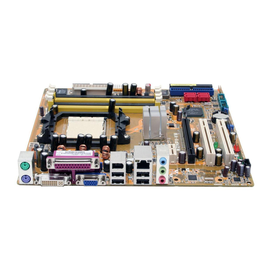
Дизайн платы отличается от модели A8N-VM CSM для Socket 939, хотя по комплектации периферийными интерфейсами обе платы практически идентичные. Компоновка не вызвала нареканий и в прошлый раз, а на этот раз в качестве еще одной положительной детали можно отметить положенный «на бок» второй порт IDE и наличие 4-контактного разъема для процессорного кулера (совместимость с 3-контактными штекерами сохранена, в том числе и в части интеллектуального управления частотой вращения).
Северный мост GeForce 6150 на большинстве плат охлаждается пассивным радиатором, что мы видим и на данной плате. Никаких замечаний по стабильности работы в наших тестах не обнаружилось (после 5-дневной нагрузки в круглосуточном режиме — на плате тестировались процессоры). Южный мост не имеет даже радиатора и, хотя в наших тестах признаков его перегрева также не обнаружилось, в тесном корпусе теплоотдача может оказаться недостаточной. Иными словами, если вы сами наклеите на него (на термоклей, поскольку других способов крепежа не предусмотрено) подходящий по размерам радиатор, вреда от такой нехитрой модификации не будет.
Разъем для подключения второго монитора совместим лишь с цифровым входом (DVI-D), так что воспользоваться переходником для подключения двух аналоговых мониторов не удастся. Кроме того, нельзя одновременно использовать аналоговый и ТВ-выход. Этими ограничениями плата обязана чипсету. Для обеспечения двухканального режима, модули памяти должны устанавливаться через один свободный разъем.
В трехканальном импульсном стабилизаторе напряжения питания применены по 3 полевых транзистора на канал, 6 конденсаторов по 1500 мкФ и 4 конденсатора по 1000 мкФ, все конденсаторы производства Matsushita, неплохой выбор для недорогой платы. Дополнительно стабилизатор напряжения памяти усилен применением индуктивных элементов.
Разведенных, но нераспаянных элементов на плате нет, эта старшая модель на базе данного чипсета, в усеченной версии M2NPV-MX отсутствует FireWire-контроллер и поддержка выхода HDTV Out. Размер платы — Micro-ATX (245×245 мм), крепление к корпусу восемью винтами (незакрепленным остается один из углов платы).
Системный мониторинг (ITE IT8716F-S, по данным BIOS Setup):
- Напряжение процессора, +3,3, +5 и +12 В;
- Частота вращения 4 вентиляторов;
- Температура процессора (встроенным датчиком процессора) и платы (встроенным датчиком платы);
- Q-Fan Control — полностью автоматическое управление частотой вращения двух вентиляторов — процессорного и подключенного к разъему Chassis Fan 1 в зависимости от температуры процессора и «системной», соответственно. Логика управления в обоих случаях одинакова, частота вращения изменяется ступенчато (примерно на 5% на каждый градус изменения температуры), составляет половину от максимальной для 40 градусов и достигает максимальной величины для 60 градусов.
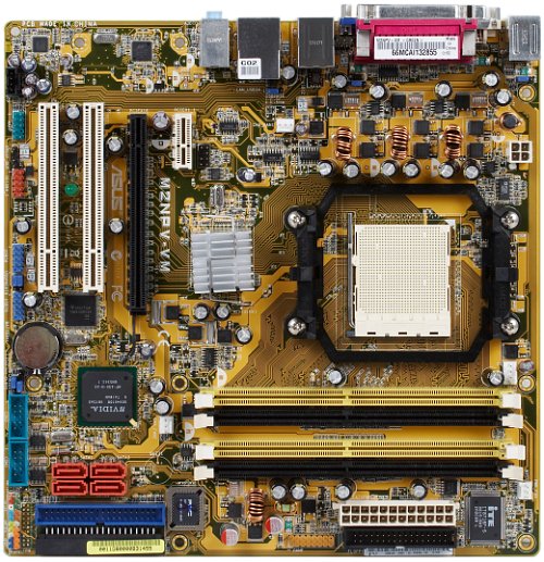
Порты, коннекторы и разъемы на поверхности платы
- Процессорный сокет (Socket AM2, заявлена поддержка всех процессоров AMD Athlon 64/X2/FX и Sempron, выпущенных для этого разъема);
- 4 разъема под DDR2 SDRAM DIMM (до 8 ГБ DDR2-400/533/667/800, двухканальный режим работы);
- 1 слот PCIEx16 для видеоускорителя;
- 1 слот PCIEx1;
- 2 слота PCI;
- Разъемы питания: стандартный ATX 2.2 (24 контакта, можно подключать обычный 20-контактный коннектор), 4-контактный ATX12V для питания процессора;
- Разъем FDD;
- 2 разъема IDE (Parallel ATA) на 4 устройства ATA133 — «чипсетные»;
- 4 разъема SATA-II (Serial ATA II) на 4 устройства SATA300 — «чипсетные», подключаемые к ним диски можно объединить в RAID-массив уровней 0, 1, 0+1, 5;
- 2 разъема для подключения планок на 4 дополнительных портов USB;
- Разъем для подключения планки с 1 портом FireWire;
- Разъем для подключения выхода звукового сигнала с CD/DVD-привода;
- Блок разъемов для подключения аналоговых входов и выходов звука на передней панели компьютера;
- Разъем для подключения датчика вскрытия корпуса;
- Разъем для подключения планки с портом S/PDIF-Out;
- Разъем для подключения планки с ТВ-выходом;
- Разъем для подключения планки с Game/MIDI-портом;
- 2 разъема для подключения 2 COM-портов;
- 4 разъема для подключения вентиляторов с возможностью контроля количества оборотов, из них процессорный 4-контактный и Chassis Fan 1 — 3-контактный с поддержкой интеллектуального управления частотой вращения (процессорный обратно совместим с вентиляторами с 3-контактными разъемами).
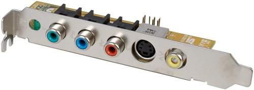
Задняя панель платы (слева направо, по блокам)
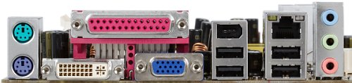
по ссылке — вид платы в 3/4 со стороны задней панели
- Разъемы PS/2 для подключения мыши и клавиатуры;
- 1 LPT, 1 DVI-D, 1 VGA;
- 2 порта USB и 1 FireWire;
- 2 порта USB и 1 RJ-45 (Gigabit Ethernet);
- 3 аналоговых аудиоразъема (Line-In (Rear Speaker Out), Line-Out (Front-Out), Mic-In (Center/Sub Speaker Out)).
Комплект поставки
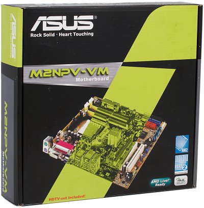
- Упаковка: небольшая коробка нового дизайна для недорогих моделей для Socket AM2;
- Документация: брошюра-руководство пользователя и отдельная многоязычная инструкция с основными сведениями по установке и настройке, в том числе и на русском языке;
- 2 кабеля Serial ATA;
- 1 переходник-разветвитель питания SATA на 2 устройства;
- 1 шлейф ATA66, 1 шлейф ATA33 (для подключения оптического привода), 1 шлейф для подключения FDD;
- Планка на заднюю панель компьютера с портом FireWire;
- Заглушка на заднюю панель платы для вывода соответствующих разъемов;
- Планка на заднюю панель с выходами HDTV, S-Video и AV, подключаемая к ТВ-выходу на плате;
- Компакт-диск с драйверами, пакетом Norton Internet Security 2006 и фирменными утилитами ASUS. Набор фирменных утилит включает:
- PC Probe II — мониторинг системных параметров (температуры: процессора и «системная», частоты вращения двух вентиляторов, напряжения, доступные в соответствующем разделе BIOS);
- AMD Cool’n’Quiet — отображение текущей частоты процессора в реальном времени);
- ASUS Live Update — перепрошивка BIOS из Windows, с возможностью поиска и закачки последней версии с сайта производителя;
- ASUS Screen Saver — редактирование загрузочной заставки BIOS.
Интегрированные контроллеры
- Звуковой, на базе «чипсетной» поддержки High Definition Audio и кодека ADI AD1986A с возможностью подключения аудиосистем 5.1, разъемами для подключения фронтальных аудиовходов/выходов, CD-In и S/PDIF-Out;
- Сетевой Gigabit Ethernet с поддержкой 10/100/1000 Мбит/с на базе чипсета (с поддержкой аппаратного брандмауэра и собственным высокоскоростным интерфейсом) и PHY-контроллера Marvell 88E1111-RCJ;
- FireWire, на базе микросхемы Texas Instruments TSB43AB22A, с поддержкой 2 портов FireWire (IEEE 1394a).
Качество интегрированного звукового решения мы оценили в режиме 16 бит, 44 кГц при помощи тестовой программы RightMark Audio Analyzer 5.5 и звуковой карты Terratec DMX 6fire:
| Неравномерность АЧХ (от 40 Гц до 15 кГц), дБ: | +0,16, -0,06 | Очень хорошо |
| Уровень шума, дБ (А): | -90,1 | Очень хорошо |
| Динамический диапазон, дБ (А): | 88,9 | Хорошо |
| Гармонические искажения, %: | 0,0041 | Очень хорошо |
| Интермодуляционные искажения + шум, %: | 0,046 | Хорошо |
| Взаимопроникновение каналов, дБ: | -88,1 | Отлично |
| Интермодуляции на 10 кГц, %: | 0,023 | Хорошо |
Общая оценка: Очень хорошо (подробнее). Реализация интегрированной аудиоподдержки оказалась на стандартно высоком уровне для современных HDA-кодеков.
Фирменные технологии и особенности
- ASUS CrashFree BIOS 2 — возможность «аварийного» восстановления поврежденного BIOS из образа, хранящегося на прилагаемом CD;
- EZ Flash BIOS — перепрошивка BIOS без необходимости загружать ОС, выполняется с помощью специальной утилиты, доступной по нажатию Alt+F2 во время прохождения POST-этапа загрузки;
- C.P.R. (CPU Parameter Recall) — автоматический сброс частоты системной шины и загрузка таймингов из SPD в случае неудачного «разгона»;
- MyLogo — изменение загрузочной заставки;
- O. C. Profiles — сохранение пользовательских настроек BIOS в отдельной области CMOS или на внешнем диске.
Настройки
| С помощью перемычек и переключателей | Перемычка для очистки CMOS | ||
| 8 перемычек «USB device wake up» | Управление функцией включения компьютера по сигналу с USB-устройств, отдельно для каждого из 8 USB-портов | ||
| Перемычка «Keyboard power» | Управление функцией включения компьютера по сигналу с клавиатуры (требуется активация соответствующего параметра в BIOS) | ||
| Из BIOS, основанного на версии 2.58 от AMI | Возможность управления специфическими функциями платформы | + | K8 Cool’n’Quiet AMD Live! |
| Настройки таймингов памяти | + | 1T/2T Memory Timing, CAS Latency, Min RAS Active Time, Row Precharge Time, RAS to CAS Delay, Row Cycle Time, Read-To-Write Time | |
| Выбор частоты работы памяти | + | Auto, 100, 133, 166, 200 (реально задается множитель относительно частоты HTT) | |
| Настройка работы шины HT | — | ||
| Возможность задания частоты для периферийных шин | — | ||
| Ручное распределение прерываний по слотам | + | ||
| Изменение частоты FSB | + | 200—400 МГц с шагом 1 МГц. Также имеется отдельная настройка «AI Tuning», позволяющая задать величину повышения частоты в процентах (3—10% с шагом 2%) | |
| Изменение коэффициента умножения процессора | + | от x5, с половинным шагом | |
| Изменение напряжения ядра процессора | — | ||
| Изменение напряжения памяти | + | Auto, 1,9 В |
Использовалась версия BIOS 0303 от 30.06.06, как последняя существующая версия на момент тестирования. Перечисленные возможности BIOS доступны в указанной прошивке, работоспособность нестандартных настроек не проверялась. ASUS по-прежнему не радует «разгонными» настройками потребителей интегрированных решений и вряд ли можно рассчитывать на изменение этой, логичной с маркетинговой точки зрения позиции, в дальнейшем.
Производительность
Конфигурация тестового стенда:
- Процессор: AMD Athlon 64 X2 4000+
- Память: 2 модуля Kingston KHX7200D2K2/1G (DDR2-800, 5-5-5-15-1T)
- Жесткий диск: Seagate Barracuda 7200.7 (SATA, 7200 об/мин)
- Видеокарта: ATI Radeon X1900XTX, 512 МБ GDDR3
- БП: Chieftec CFT-560-A12C
- ОС: Windows XP SP2
Поскольку данная модель — первая с разъемом Socket AM2 на чипсете GeForce 6150 из протестированных в нашей лаборатории, для сравнения использованы результаты Foxconn 6100M2MA-RS2H на чипсете GeForce 6100.
| Тест | интегрированная графика | внешняя графика | ||
| Foxconn 6100M2MA | ASUS M2NPV-VM | Foxconn 6100M2MA | ASUS M2NPV-VM | |
|---|---|---|---|---|
| Архивирование в 7-Zip, мин:сек | 6:48 | 6:40 | 6:45 | 6:43 |
| Кодирование MPEG4 (XviD), мин:сек | 6:08 | 6:05 | 6:05 | 6:02 |
| Unreal Tournament 2004 (Low@640×480), fps | 44,4 | 47,8 | 76,7 | 77,6 |
| Unreal Tournament 2004 (Highest@1600×1200), fps | 9,5 | 21,8 | 72,3 | 74,0 |
| FarCry (Medium@800×600), fps | 30,8 | 31,3 | 126,5 | 129,4 |
| DOOM III (Medium@800×600), fps | 12,9 | 13,7 | 133,0 | 135,0 |
Сравнение моделей на младшем и старшем интегрированном чипсетах от NVIDIA интересно само по себе и показательно тем, что предложение плат на GeForce 6100 под Socket AM2 обещает быть более распространенным. По крайней мере, в списке уже выпущенных плат, представительство моделей на «младшей» версии на сегодня богаче, и они имеются в линейках всех действующих производителей, тогда как о GeForce 6150 «позаботились» лишь наиболее активные.
Официально, это объясняется тем, что богатый функциями чипсет GeForce 6150 мешал «правильно» позиционировать модели на младших дискретных чипсетах (и поэтому они, в свою очередь, были представлены слабее). Но, как мы видим, различие в производительности графического ядра у этих чипсетов на практике невелико (лишь Unreal Tournament 2004 в режиме высокого качества продемонстрировал зримую разницу, что позволяет сделать вывод о более высокой скорости закраски в условиях неотягощенной шейдерами графики, но такая ситуация уже давно редкость).
Разумеется, остается различие в функциональности южных мостов nForce 410 и 430. Но не будет большим грехом против истины полагать, что на практике, выбирая плату с интегрированным ядром, стоит учесть модели на обоих чипсетах и выбрать ту, которая, по реализованной функциональности и прочим признакам, окажется наиболее удовлетворяющей вашим требованиям.
Вывод
Компания ASUS выпустила для Socket AM2 на чипсете GeForce 6150 не менее интересную модель по сравнению с A8N-VM CSM для Socket 939. Однако, и ничего неожиданного со сменой процессорного разъема не добавилось, стандартно установленные разъемы VGA и DVI-D остаются центральной опцией платы. По-прежнему аскетичный BIOS и пассивная система охлаждения без явного запаса теплоемкости не позволяют использовать эту плату в экспериментах с разгоном.
Плата предоставлена на тестирование производителем