Если у вас отсутствует техническая возможность для скачивания Руководство по эксплуатации для ASUS M4A77TD
вы можете прочесть документ прямо на нашем сайте или
Скачать ASUS M4A77TD Руководство по эксплуатации

- 1
- 2
- 3
- 4
- 5
- 6
- 7
- 8
- 9
- 10
- 11
- 12
- 13
- 14
- 15
- 16
- 17
- 18
- 19
- 20
- 21
- 22
- 23
- 24
- 25
- 26
- 27
- 28
- 29
- 30
- 31
- 32
- 33
- 34
- 35
- 36
- 37
- 38
- 39
- 40
- 41
- 42
- 43
- 44
- 45
- 46
- 47
- 48
- 49
- 50
- 51
- 52
- 53
- 54
- 55
- 56
- 57
- 58
- 59
- 60
- 61
- 62
- 63
- 64
- 65
Инструкции для прочих ASUS Материнские платы
Инструкции для прочих ASUS
-
Contents
-
Table of Contents
-
Bookmarks
Quick Links
Related Manuals for Asus M4A77TD — Motherboard — ATX
Summary of Contents for Asus M4A77TD — Motherboard — ATX
-
Page 1
M4A77TD… -
Page 2
Product warranty or service will not be extended if: (1) the product is repaired, modified or altered, unless such repair, modification of alteration is authorized in writing by ASUS; or (2) the serial number of the product is defaced or missing. -
Page 3: Table Of Contents
Welcome! ………………1-1 Package contents …………….. 1-1 Special features …………….1-1 1.3.1 Product highlights …………1-1 1.3.2 Innovative ASUS features ……….1-3 Before you proceed …………..1-5 Motherboard overview …………..1-6 1.5.1 Placement direction …………1-6 1.5.2 Screw holes …………..1-6 1.5.3…
-
Page 4
Chapter 2: BIOS information Managing and updating your BIOS ……….2-1 2.1.1 ASUS Update utility …………2-1 2.1.2 ASUS EZ Flash 2 utility ……….. 2-3 2.1.3 ASUS CrashFree BIOS utility ……… 2-4 BIOS setup program …………..2-5 2.2.1 BIOS menu screen …………2-6 2.2.2… -
Page 5
Boot Device Priority …………2-19 2.6.2 Boot Settings Configuration ………. 2-20 2.6.3 Security …………….. 2-21 Tools menu …………….. 2-22 2.7.1 ASUS EZ Flash 2 …………2-23 2.7.2 Express Gate …………..2-23 2.7.3 AI NET 2……………. 2-23 Exit menu ………………2-24… -
Page 6: Notices
Complying with the REACH (Registration, Evaluation, Authorisation, and Restriction of Chemicals) regulatory framework, we published the chemical substances in our products at ASUS REACH website at http://green.asus.com/english/REACH.htm. DO NOT throw the motherboard in municipal waste. This product has been designed to enable proper reuse of parts and recycling.
-
Page 7: Safety Information
Safety information Electrical safety • To prevent electric shock hazard, disconnect the power cable from the electric outlet before relocating the system. • When adding or removing devices to or from the system, ensure that the power cables for the devices are unplugged before the signal cables are connected. If possible, disconnect all power cables from the existing system before you add a device.
-
Page 8: About This Guide
Operation safety • Before installing the motherboard and adding devices on it, carefully read all the manuals that came with the package. • Before using the product, ensure that all cables are correctly connected and the power cables are not damaged. If you detect any damage, contact your dealer immediately. •…
-
Page 9: Conventions Used In This Guide
Refer to the following sources for additional information and for product and software updates. ASUS websites The ASUS website provides updated information on ASUS hardware and software products. Refer to the ASUS contact information. Optional documentation Your product package may include optional documentation, such as warranty flyers, that may have been added by your dealer.
-
Page 10: M4A77Td Specifications Summary
4 x 240-pin DIMM slots support maximum 16GB unbuffered ECC and non-ECC DDR3 1800(O.C.) / 1600(O.C.) / 1333 / 1066MHz memory modules * Refer to www.asus.com for the latest Memory QVL (Qualified Vendors List). ** When you install a total memory of 4GB or more,…
-
Page 11
– FSB tuning from 200MHz to 550MHz at 1MHz increment – PCIe frequency tuning from 100MHz to 150MHz at 1MHz increment ASUS C.P.R. (CPU Parameter Recall) Accessories 2 x Serial ATA cables 1 x Ultra DMA 133/100/66 cable 1 x I/O shield… -
Page 13: Chapter 1: Product Introduction
® The motherboard delivers a host of new features and latest technologies, making it another standout in the long line of ASUS quality motherboards! Before you start installing the motherboard, and hardware devices on it, check the items in your package with the list below.
-
Page 14
770 Chipset ® The AMD 770 Chipset is designed to support up to 5200MT/s ® HyperTransport™ 3.0 (HT 3.0) interface speed and PCI Express 2.0 x16 graphics. It is optimized with AMD’s latest AM3 multi-core CPUs to provide excellent system performance and overclocking capabilities. HyperTransport™… -
Page 15: Innovative Asus Features
USB port before turning on the computer. • The actual boot time depends on the system configuration. • ASUS Express Gate supports file uploading from SATA HDDs, ODDs and USB drives. It supports file downloading to USB drives only.
-
Page 16: Asus Mylogo2
BIOS file using the bundled support DVD or a USB flash disk that contains the BIOS file. ASUS EZ Flash 2 ASUS EZ Flash 2 allows you to update the BIOS from a USB flash disk before entering the OS. ASUS Q-Fan…
-
Page 17: Before You Proceed
ON, in sleep mode, or in soft-off mode. This is a reminder that you should shut down the system and unplug the power cable before removing or plugging in any motherboard component. The illustration below shows the location of the onboard LED. SB_PWR M4A77TD Standby Power Powered Off M4A77TD Onboard power LED ASUS M4A77TD…
-
Page 18: Motherboard Overview
Motherboard overview 1.5.1 Placement direction When installing the motherboard, ensure that you place it into the chassis in the correct orientation. The edge with external ports goes to the rear part of the chassis as indicated in the image below. 1.5.2 Screw holes Place six screws into the holes indicated by circles to secure the motherboard to the chassis.
-
Page 19: Motherboard Layout
10. Onboard power LED (SB_PWR) IDE connector (40-1 pin PRI_IDE) 1-22 11. Digital audio connector (4-1 pin SPDIF_OUT) 1-26 SATA connectors (7-pin SATA1, SATA2, SATA3, SATA4, 1-23 12. Front panel audio connector (10-1 pin AAFP) 1-26 SATA5, and SATA6) ASUS M4A77TD…
-
Page 20: Central Processing Unit (Cpu)
Central Processing Unit (CPU) This motherboard comes with an AM3 socket designed for Phenom™ II / Athlon™ II / Sempron™ 100 series processors. The AM3 socket has a different pinout from the AM2+/AM2 socket. Ensure that you use a CPU designed for the AM3 socket. The CPU fits in only one correct orientation. DO NOT force the CPU into the socket to prevent bending the pins and damaging the CPU! 1.6.1 Installing the CPU…
-
Page 21
Connect the CPU fan cable to the CPU_FAN connector on the motherboard. CPU_FAN CPU FAN PWR CPU FAN IN CPU FAN PWM M4A77TD M4A77TD CPU fan connector DO NOT forget to connect the CPU fan connector! Hardware monitoring errors can occur if you fail to plug this connector. ASUS M4A77TD… -
Page 22: Installing The Heatsink And Fan
1.6.2 Installing the heatsink and fan Ensure that you use only AMD-certified heatsink and fan assembly. To install the CPU heatsink and fan: Place the heatsink on top of the installed CPU, ensuring that the heatsink fits properly on the retention module base. •…
-
Page 23: System Memory
DDR2 DIMM socket. DDR3 modules are developed for better performance with less power consumption. The figure illustrates the location of the DDR3 DIMM sockets: Channel Sockets Channel A DIMM_A1 and DIMM_A2 Channel B DIMM_B1 and DIMM_B2 M4A77TD M4A77TD 240-pin DDR3 DIMM sockets ASUS M4A77TD 1-11…
-
Page 24: Memory Configurations
1.7.2 Memory configurations You may install 512MB, 1GB, 2GB, and 4GB unbuffered ECC and non-ECC DDR3 DIMMs into the DIMM sockets. • You may install varying memory sizes in Channel A and Channel B. The system maps the total size of the lower-sized channel for the dual-channel configuration. Any excess memory from the higher-sized channel is then mapped for single-channel operation.
-
Page 25
• 3072MB(Kit G.SkiLL F3-10666CL7T-3GBPK Heat-Sink Package 7-7-7-18 • • • of 3) 3072MB(Kit G.SkiLL F3-10666CL9T-3GBNQ Heat-Sink Package 9-9-9-24 • • • of 3) G.SKILL F3-10600CL7D-2GBPI 1024MB G.SKILL Heat-Sink Package • • • (continued on the next page) ASUS M4A77TD 1-13… -
Page 26
DDR3-1333MHz capability DIMM support Vendor Part No. Size Chip Brand Chip NO. G.SKILL F3-10600CL9D-2GBNQ 1024MB G.SKILL Heat-Sink Package • • • G.SKILL F3-10666CL9D-4GBPK 2048MB G.SKILL Heat-Sink Package • • • 6144MB(Kit G.SkiLL F3-10666CL7T-6GBPK Heat-Sink Package 7-7-7-18 • • • of 3 ) 6144MB(Kit G.SKILL F3-1066CL9T-6GBNQ… -
Page 27
• C*: Supports two pairs of modules inserted into both the blue slots and the black slots as two pairs of dual-channel memory configuration. Visit the ASUS website at www.asus.com for the latest QVL. ASUS M4A77TD 1-15… -
Page 28: Installing A Dimm
1.7.3 Installing a DIMM Unplug the power supply before adding or removing DIMMs or other system components. Failure to do so can cause severe damage to both the motherboard and the components. Press the retaining clips outward to DIMM notch unlock a DIMM socket.
-
Page 29: Expansion Slots
This motherboard supports PCI Express x1 network cards, SCSI cards, and other cards that comply with the PCI Express specifications. 1.8.5 PCI Express x16 slot This motherboard supports a PCI Express x16 graphics card that comply with the PCI Express specifications. ASUS M4A77TD 1-17…
-
Page 30: Jumpers
Jumpers Clear RTC RAM (CLRTC) This jumper allows you to clear the Real Time Clock (RTC) RAM in CMOS. You can clear the CMOS memory of date, time, and system setup parameters by erasing the CMOS RTC RAM data. The onboard button cell battery powers the RAM data in CMOS, which include system setup information such as system passwords.
-
Page 31: Connectors
Side Speaker Out port (gray). This port connects to the side speakers in the 8-channel audio configuration. Refer to the audio configuration table on the next page for the function of the audio ports in the 2, 4, 6, or 8-channel configuration. ASUS M4A77TD 1-19…
-
Page 32
Audio 2, 4, 6, or 8-channel configuration Headset Port 4-channel 6-channel 8-channel 2-channel Light Blue Line In Line In Line In Line In Lime Line Out Front Speaker Out Front Speaker Out Front Speaker Out Pink Mic In Mic In Mic In Mic In Orange… -
Page 33: Internal Connectors
The system may become unstable or may not boot up if the power is inadequate. • If you are uncertain about the minimum power supply requirement for your system, refer to the Recommended Power Supply Wattage Calculator at http://support.asus. com/PowerSupplyCalculator/PSCalculator.aspx?SLanguage=en-us for details. ASUS M4A77TD…
-
Page 34
IDE connector (40-1 pin PRI_IDE) The onboard IDE connector is for Ultra DMA 133/100/66 signal cable. There are three connectors on each Ultra DMA 133/100/66 signal cable: blue, black, and gray. Connect the blue connector to the motherboard’s IDE connector, then select one of the following modes to configure your devices: Drive jumper setting Mode of device(s) -
Page 35
XP limitation, Windows XP may not recognize the USB floppy disk ® ® drive. • For more details on RAID/AHCI, refer to the RA ID/AHCI Supplementary Guide included in the folder named Manual in the support DVD. ASUS M4A77TD 1-23… -
Page 36: System Panel Connector
System panel connector (20-8 pin PANEL) This connector supports several chassis-mounted functions. PLED SPEAKER PANEL PIN 1 M4A77TD IDE_LED PWRSW RESET * Requires an ATX power supply M4A77TD System panel connector • System power LED This 2-pin connector is for the system power LED. Connect the chassis power LED cable to this connector.
-
Page 37
480Mbps connection speed. USB78 USB1112 USB910 M4A77TD PIN 1 PIN 1 PIN 1 M4A77TD USB2.0 connectors Never connect a 1394 cable to the USB connectors. Doing so will damage the motherboard! The USB 2.0 module is purchased separately. ASUS M4A77TD 1-25… -
Page 38: Front Panel Audio Connector
Digital audio connector (4-1 pin SPDIF_OUT) This connector is for an additional Sony/Philips Digital Interface (S/PDIF) port. M4A77TD SPDIF_OUT M4A77TD Digital audio connector Ensure that the audio device of Sound playback is VIA High Definition Audio (the name may be different based on the OS). Go to Start > Control Panel > Sounds and Audio Devices >…
-
Page 39
DO NOT forget to connect the fan cables to the fan connectors. Insufficient air flow inside the system may damage the motherboard components. These are not jumpers! DO NOT place jumper caps on the fan connectors. Only the 4-pin CPU fan supports the ASUS Q-Fan feature. ASUS M4A77TD 1-27… -
Page 40: Software Support
The contents of the Support DVD are subject to change at any time without notice. Visit the ASUS website at www.asus.com for updates. To run the Support DVD Place the Support DVD into the optical drive.
-
Page 41: Chapter 2: Bios Information
BIOS in the future. Copy the original motherboard BIOS using the ASUS Update utility. 2.1.1 ASUS Update utility The ASUS Update is a utility that allows you to manage, save, and update the motherboard BIOS in Windows environment. ®…
-
Page 42: Updating The Bios
Updating from the Internet Select Update BIOS from the Internet, then click Next. Select the ASUS FTP site nearest you to avoid network traffic, or click Auto Select then click Next. From the FTP site, select the BIOS version that you want to download then click Next.
-
Page 43: Asus Ez Flash 2 Utility
2.1.2 ASUS EZ Flash 2 utility The ASUS EZ Flash 2 feature allows you to update the BIOS without using an OS-based utility. Before you start using this utility, download the latest BIOS file from the ASUS website at www.asus.com.
-
Page 44: Asus Crashfree Bios Utility
2.1.3 ASUS CrashFree BIOS utility The ASUS CrashFree BIOS is an auto recovery tool that allows you to restore the BIOS file when it fails or gets corrupted during the updating process. You can restore a corrupted BIOS file using the motherboard support DVD or a removable device that contains the updated BIOS file.
-
Page 45: Bios Setup Program
• The BIOS setup screens in this chapter are for reference only. They may not exactly match what you see on your screen. • Visit the ASUS website at www.asus.com to download the latest BIOS file for this motherboard. ASUS M4A77TD…
-
Page 46: Bios Menu Screen
2.2.1 BIOS menu screen Menu items Menu bar Configuration fields General help BIOS SETUP UTILITY Main Advanced Power Boot Tools Exit Main Settings Use [ENTER], [TAB] System Time [19:34:30] or [SHIFT-TAB] to System Date [Fri 07/31/2009] select a field. Primary IDE Master :[Not Detected] Use [+] or [-] to Primary IDE Slave…
-
Page 47: Menu Items
Press the <Up> / <Down> arrow keys or <Page Up> /<Page Down> keys to display the other items on the screen. 2.2.9 General help At the top right corner of the menu screen is a brief description of the selected item. ASUS M4A77TD…
-
Page 48: Main Menu
Main menu When you enter the BIOS Setup program, the Main menu screen appears, giving you an overview of the basic system information. Refer to section 2.2.1 BIOS menu screen for information on the menu screen items and how to navigate through them. BIOS SETUP UTILITY Main Advanced…
-
Page 49: Sata Configuration
OS. Ensure to install the AHCI driver, so that you can use SATA 1/2/3/4/5/6 in AHCI mode under OS. • When SATA 1/2/3/4 are configured as [AHCI] and SATA 5/6 are configured as [IDE], you can access the devices on SATA 5/6 before entering OS. ASUS M4A77TD…
-
Page 50: System Information
2.3.5 System Information This menu gives you an overview of the general system specifications. The BIOS automatically detects the items in this menu. BIOS Information Displays the auto-detected BIOS information. Processor Displays the auto-detected CPU specification. System Memory Displays the auto-detected system memory. Advanced menu The Advanced menu items allow you to change the settings for the CPU and other system devices.
-
Page 51
HT Over Voltage [Auto] Sets the HT over voltage. The values range from 1.25000V to 1.38500V with a 0.01500V increment. Use the <+> / <-> keys to adjust the value. Configuration options: [Auto] [Max. = 1.38500V] [Min. = 1.25000V] ASUS M4A77TD 2-11… -
Page 52
DRAM Frequency [Auto] Selects the DRAM frequency programming method. If this item is set to [Auto], the DRAM speed depends on the SPDs. Configuration options: [Auto] [800MHz] [1067MHz] [1333MHz] [1600MHz] Memory Over Voltage [Auto] Sets the memory over voltage. The values range from 1.5000V to 2.2050V with a 0.0150V increment. -
Page 53: Cpu Configuration
Enables or disables Secure Virtual Machine Mode (SVM). Configuration options: [Disabled] [Enabled] Cool ‘n’ Quiet [Enabled] Enables or disables the AMD Cool ‘n’ Quiet technology. Configuration options: [Enabled] ® [Disabled] ACPI SRAT Table [Enabled] Enables or disables the building of ACPI SRAT table. Configuration options: [Enabled] [Disabled] ASUS M4A77TD 2-13…
-
Page 54: Chipset
C1E Configuration [Disabled] Enables or disables the CPU Enhanced Halt (C1E) function, a CPU power-saving function in system halt state. When this item is enabled, the CPU core frequency and voltage will be reduced during the system halt state to decrease power consumption. Configuration options: [Disabled] [Enabled] Advanced Clock Calibration [Disabled] Adjusts the processor’s overclocking capability.
-
Page 55: Onboard Device Configuration
When this item is set to [No], BIOS configures all the devices in the system. When this item is set to [Yes] and if you install a Plug and Play operating system, the operating system configures the Plug and Play devices not required for boot. Configuration options: [No] [Yes] ASUS M4A77TD 2-15…
-
Page 56: Usb Configuration
2.4.6 USB Configuration The items in this menu allows you to change the USB-related features. Select an item then press <Enter> to display the configuration options. The Module Version and USB Devices Enabled items show the auto-detected values. If no USB device is detected, the item shows None.
-
Page 57: Power Menu
Power on From S5 By PME# [Disabled] Enables or disables PME wake from sleep states. Configuration options: [Disabled] [Enabled] Power on From S5 By Ring [Disabled] Enables or disables ring to generate a wake event. Configuration options: [Disabled] [Enabled] ASUS M4A77TD 2-17…
-
Page 58: Hw Monitor Configuration
The onboard hardware monitor automatically detects the voltage output through the onboard voltage regulators. Smart Q-Fan Function [Enabled] Enables or disables the ASUS Q-Fan feature that smartly adjusts the CPU fan speeds for more efficient system operation. Configuration options: [Disabled] [Enabled] Fan Auto Mode Start Voltage [5.0V] Selects the fan auto mode start voltage.
-
Page 59: Boot Menu
Configuration options: [Removable Dev.] [Hard Drive] [ATAPI CD-ROM] [Disabled] • To select the boot device during system startup, press <F8> when ASUS logo appears. • To access Windows OS in Safe Mode, do any of the following: •…
-
Page 60: Boot Settings Configuration
Enables or disables the full screen logo display feature. Configuration options: [Disabled] [Enabled] Set this item to [Enabled] to use the ASUS MyLogo2™ feature. AddOn ROM Display Mode [Force BIOS] Sets the display mode for option ROM. Configuration options: [Force BIOS] [Keep Current] Bootup Num-Lock [On] Selects the power-on state for the NumLock.
-
Page 61: Security
View Only allows access but does not allow change to any field. Limited allows changes only to selected fields, such as Date and Time. Full Access allows viewing and changing all the fields in the Setup utility. ASUS M4A77TD 2-21…
-
Page 62: Tools Menu
<Enter> to display the sub-menu. BIOS SETUP UTILITY Main Advanced Power Boot Tools Exit Press ENTER to run ASUS EZ Flash 2 the utility to select and update BIOS. This utility supports: Express Gate [Auto] 1.FAT 12/16/32 (r/w) Enter OS Timer [10 Seconds] 2.NTFS (read only)
-
Page 63: Asus Ez Flash 2
2.7.1 ASUS EZ Flash 2 Allows you to run ASUS EZ Flash 2. When you press <Enter>, a confirmation message appears. Use the left/right arrow key to select between [Yes] or [No], then press <Enter> to confirm your choice. 2.7.2 Express Gate [Auto] Allows you to enable or disable the ASUS Express Gate feature.
-
Page 64: Exit Menu
Exit menu The Exit menu items allow you to load the optimal or failsafe default values for the BIOS items, and save or discard your changes to the BIOS items. BIOS SETUP UTILITY Main Advanced Power Boot Tools Exit Exit Options Exit system setup after saving the Exit &…
-
Драйверы
39
-
Инструкции по эксплуатации
2
Языки:

ASUS M4A77TD инструкция по эксплуатации
(60 страниц)
- Языки:Французский
-
Тип:
PDF -
Размер:
2.58 MB -
Описание:
M4A77TD user’s manual (French)
Просмотр

ASUS M4A77TD инструкция по эксплуатации
(62 страницы)
- Языки:Китайский
-
Тип:
PDF -
Размер:
2.74 MB -
Описание:
M4A77TD user’s manual (Traditional Chinese)
Просмотр
На NoDevice можно скачать инструкцию по эксплуатации для ASUS M4A77TD. Руководство пользователя необходимо для ознакомления с правилами установки и эксплуатации ASUS M4A77TD. Инструкции по использованию помогут правильно настроить ASUS M4A77TD, исправить ошибки и выявить неполадки.
E4944
First Edition V1
August 2009
Copyright © 2009 ASUSTeK Computer Inc. All Rights Reserved.
No part of this manual, including the products and software described in it, may be reproduced,
transmitted, transcribed, stored in a retrieval system, or translated into any language in any form or by any
means, except documentation kept by the purchaser for backup purposes, without the express written
permission of ASUSTeK Computer Inc. («ASUS»).
Product warranty or service will not be extended if: (1) the product is repaired, modified or altered, unless
such repair, modification of alteration is authorized in writing by ASUS; or (2) the serial number of the
product is defaced or missing.
ASUS PROVIDES THIS MANUAL «AS IS» WITHOUT WARRANTY OF ANY KIND, EITHER EXPRESS
OR IMPLIED, INCLUDING BUT NOT LIMITED TO THE IMPLIED WARRANTIES OR CONDITIONS OF
MERCHANTABILITY OR FITNESS FOR A PARTICULAR PURPOSE. IN NO EVENT SHALL ASUS, ITS
DIRECTORS, OFFICERS, EMPLOYEES OR AGENTS BE LIABLE FOR ANY INDIRECT, SPECIAL,
INCIDENTAL, OR CONSEQUENTIAL DAMAGES (INCLUDING DAMAGES FOR LOSS OF PROFITS,
LOSS OF BUSINESS, LOSS OF USE OR DATA, INTERRUPTION OF BUSINESS AND THE LIKE),
EVEN IF ASUS HAS BEEN ADVISED OF THE POSSIBILITY OF SUCH DAMAGES ARISING FROM ANY
DEFECT OR ERROR IN THIS MANUAL OR PRODUCT.
SPECIFICATIONS AND INFORMATION CONTAINED IN THIS MANUAL ARE FURNISHED FOR
INFORMATIONAL USE ONLY, AND ARE SUBJECT TO CHANGE AT ANY TIME WITHOUT NOTICE,
AND SHOULD NOT BE CONSTRUED AS A COMMITMENT BY ASUS. ASUS ASSUMES NO
RESPONSIBILITY OR LIABILITY FOR ANY ERRORS OR INACCURACIES THAT MAY APPEAR IN THIS
MANUAL, INCLUDING THE PRODUCTS AND SOFTWARE DESCRIBED IN IT.
Products and corporate names appearing in this manual may or may not be registered trademarks or
copyrights of their respective companies, and are used only for identification or explanation and to the
owners’ benefit, without intent to infringe.
ii
Инструкции и Руководства для Asus M4A77TD.
Мы нашли 7
инструкции доступные для бесплатного скачивания:
Инструкция по началу работы, Инструкция по применению, Руководство пользователя

Asus M4A77TD Motherboard Guide de démarrage rapide
Бренд:
Asus
Категория:
Memory modules
Размер:
1 MB
Страниц:
42
Язык(и):
Болгарский, Чешский, Немецкий, Испанский, Французский, Хорватский, Венгерский, Итальянский, Польский, Португальский, Румынский, Русский, Турецкий
Открыть в новой вкладке

ASUS M4A77TD Owner’s Manual
Бренд:
Asus
Категория:
Motherboards
Размер:
3 MB
Страниц:
64
Язык(и):
Английский
Открыть в новой вкладке

Asus M4A77TD Motherboard Guide de démarrage rapide
Бренд:
Asus
Размер:
3 MB
Страниц:
26
Язык(и):
Французский, Индонезийский, Японский, Корейский, Тайский, Вьетнамский
Открыть в новой вкладке

Asus M4A77TD Motherboard Benutzerhandbuch
Бренд:
Asus
Категория:
Motherboards
Размер:
2 MB
Страниц:
66
Язык(и):
Немецкий
Открыть в новой вкладке

Asus M4A77TD Motherboard ユーザーマニュアル
Бренд:
Asus
Категория:
Motherboards
Размер:
2 MB
Страниц:
62
Язык(и):
Японский, zh
Открыть в новой вкладке

Asus M4A77TD Motherboard ユーザーマニュアル
Бренд:
Asus
Категория:
Motherboards
Размер:
2 MB
Страниц:
64
Язык(и):
Японский, zh
Открыть в новой вкладке

Asus M4A77TD Motherboard User Manual
Бренд:
Asus
Размер:
2 MB
Страниц:
64
Язык(и):
Английский
Открыть в новой вкладке
 Loading…
![]()

E4944
First Edition V1
August 2009
Copyright © 2009 ASUSTeK Computer Inc. All Rights Reserved.
No part of this manual, including the products and software described in it, may be reproduced, transmitted, transcribed, stored in a retrieval system, or translated into any language in any form or by any means, except documentation kept by the purchaser for backup purposes, without the express written permission of ASUSTeK Computer Inc. (“ASUS”).
Product warranty or service will not be extended if: (1) the product is repaired, modified or altered, unless such repair, modification of alteration is authorized in writing by ASUS; or (2) the serial number of the product is defaced or missing.
ASUS PROVIDES THIS MANUAL “AS IS” WITHOUT WARRANTY OF ANY KIND, EITHER EXPRESS OR IMPLIED, INCLUDING BUT NOT LIMITED TO THE IMPLIED WARRANTIES OR CONDITIONS OF MERCHANTABILITY OR FITNESS FOR A PARTICULAR PURPOSE. IN NO EVENT SHALL ASUS, ITS DIRECTORS, OFFICERS, EMPLOYEES OR AGENTS BE LIABLE FOR ANY INDIRECT, SPECIAL, INCIDENTAL, OR CONSEQUENTIAL DAMAGES (INCLUDING DAMAGES FOR LOSS OF PROFITS, LOSS OF BUSINESS, LOSS OF USE OR DATA, INTERRUPTION OF BUSINESS AND THE LIKE), EVEN IF ASUS HAS BEEN ADVISED OF THE POSSIBILITY OF SUCH DAMAGES ARISING FROM ANY DEFECT OR ERROR IN THIS MANUAL OR PRODUCT.
SPECIFICATIONS AND INFORMATION CONTAINED IN THIS MANUAL ARE FURNISHED FOR INFORMATIONAL USE ONLY, AND ARE SUBJECT TO CHANGE AT ANY TIME WITHOUT NOTICE, AND SHOULD NOT BE CONSTRUED AS A COMMITMENT BY ASUS. ASUS ASSUMES NO RESPONSIBILITY OR LIABILITY FOR ANY ERRORS OR INACCURACIES THAT MAY APPEAR IN THIS MANUAL, INCLUDING THE PRODUCTS AND SOFTWARE DESCRIBED IN IT.
Products and corporate names appearing in this manual may or may not be registered trademarks or copyrights of their respective companies, and are used only for identification or explanation and to the owners’ benefit, without intent to infringe.
ii

Contents
|
Notices…………………………………………………………………………………………… |
vi |
|
Safety information………………………………………………………………………….. |
vii |
|
About this guide……………………………………………………………………………. |
viii |
|
M4A77TD specifications summary……………………………………………………. |
x |
Chapter 1: Product introduction
|
1.1 |
Welcome!…………………………………………………………………………… |
1-1 |
|
|
1.2 |
Package contents………………………………………………………………. |
1-1 |
|
|
1.3 |
Special features…………………………………………………………………. |
1-1 |
|
|
1.3.1 |
Product highlights …………………………………………………… |
1-1 |
|
|
1.3.2 |
Innovative ASUS features ………………………………………… |
1-3 |
|
|
1.4 |
Before you proceed……………………………………………………………. |
1-5 |
|
|
1.5 |
Motherboard overview……………………………………………………….. |
1-6 |
|
|
1.5.1 |
Placement direction ………………………………………………… |
1-6 |
|
|
1.5.2 |
Screw holes …………………………………………………………… |
1-6 |
|
|
1.5.3 |
Motherboard layout …………………………………………………. |
1-7 |
|
|
1.5.4 |
Layout contents . …………………………………………………….. |
1-7 |
|
|
1.6 |
Central Processing Unit (CPU)……………………………………………. |
1-8 |
|
|
1.6.1 |
Installing the CPU …………………………………………………… |
1-8 |
|
|
1.6.2 |
Installing the heatsink and fan ………………………………… |
1-10 |
|
|
1.7 |
System memory……………………………………………………………….. |
1-11 |
|
|
1.7.1 |
Overview ………………………………………………………………. |
1-11 |
|
|
1.7.2 |
Memory configurations . …………………………………………. |
1-12 |
|
|
1.7.3 |
Installing a DIMM ………………………………………………….. |
1-16 |
|
|
1.7.4 |
Removing a DIMM ………………………………………………… |
1-16 |
|
|
1.8 |
Expansion slots……………………………………………………………….. |
1-17 |
|
|
1.8.1 |
Installing an expansion card …………………………………… |
1-17 |
|
|
1.8.2 |
Configuring an expansion card ……………………………….. |
1-17 |
|
|
1.8.3 |
PCI slots . …………………………………………………………….. |
1-17 |
|
|
1.8.4 |
PCI Express x1 slots …………………………………………….. |
1-17 |
|
|
1.8.5 |
PCI Express x16 slot . ……………………………………………. |
1-17 |
|
|
1.9 |
Jumpers |
…………………………………………………………………………… |
1-18 |
|
1.10 |
Connectors………………………………………………………………………. |
1-19 |
|
|
1.10.1 …………………………………………………… |
Rear panel ports |
1-19 |
|
|
1.10.2 ……………………………………………….. |
Internal connectors |
1-21 |
iii

Contents
|
1.11 Software support……………………………………………………………… |
1-28 |
|
|
1.11.1 |
Installing an operating system………………………………… |
1-28 |
|
1.11.2 |
Support DVD information……………………………………….. |
1-28 |
Chapter 2: BIOS information
|
2.1 |
Managing and updating your BIOS……………………………………… |
2-1 |
|
|
2.1.1 |
ASUS Update utility………………………………………………… |
2-1 |
|
|
2.1.2 |
ASUS EZ Flash 2 utility.………………………………………….. |
2-3 |
|
|
2.1.3 |
ASUS CrashFree BIOS utility…………………………………… |
2-4 |
|
|
2.2 |
BIOS setup program…………………………………………………………… |
2-5 |
|
|
2.2.1 |
BIOS menu screen.………………………………………………… |
2-6 |
|
|
2.2.2 |
Menu bar………………………………………………………………. |
2-6 |
|
|
2.2.3 |
Navigation keys.…………………………………………………….. |
2-6 |
|
|
2.2.4 |
Menu items……………………………………………………………. |
2-7 |
|
|
2.2.5 |
Submenu items………………………………………………………. |
2-7 |
|
|
2.2.6 |
Configuration fields…………………………………………………. |
2-7 |
|
|
2.2.7 |
Pop-up window………………………………………………………. |
2-7 |
|
|
2.2.8 |
Scroll bar………………………………………………………………. |
2-7 |
|
|
2.2.9 |
General help………………………………………………………….. |
2-7 |
|
|
2.3 |
Main menu…………………………………………………………………………. |
2-8 |
|
|
2.3.1 |
System Time………………………………………………………….. |
2-8 |
|
|
2.3.2 |
System Date………………………………………………………….. |
2-8 |
|
|
2.3.3 |
Primary IDE Master/Slave, SATA 1/2/3/4/5/6………………. |
2-8 |
|
|
2.3.4 |
SATA Configuration…………………………………………………. |
2-9 |
|
|
2.3.5 |
System Information……………………………………………….. |
2-10 |
|
|
2.4 |
Advanced menu……………………………………………………………….. |
2-10 |
|
|
2.4.1 |
JumperFree Configuration……………………………………… |
2-10 |
|
|
2.4.2 |
CPU Configuration………………………………………………… |
2-13 |
|
|
2.4.3 |
Chipset……………………………………………………………….. |
2-14 |
|
|
2.4.4 |
Onboard Device Configuration.………………………………. |
2-15 |
|
|
2.4.5 |
PCIPnP……………………………………………………………….. |
2-15 |
|
|
2.4.6 |
USB Configuration………………………………………………… |
2-16 |
iv

Contents
|
2.5 |
Power menu…………………………………………………………………….. |
2-17 |
|
|
2.5.1 |
Suspend Mode…………………………………………………….. |
2-17 |
|
|
2.5.2 |
ACPI 2.0 Support………………………………………………….. |
2-17 |
|
|
2.5.3 |
ACPI APIC Support………………………………………………. |
2-17 |
|
|
2.5.4 |
APM Configuration……………………………………………….. |
2-17 |
|
|
2.5.5 |
HW Monitor Configuration.…………………………………….. |
2-18 |
|
|
2.6 |
Boot menu……………………………………………………………………….. |
2-19 |
|
|
2.6.1 |
Boot Device Priority………………………………………………. |
2-19 |
|
|
2.6.2 |
Boot Settings Configuration……………………………………. |
2-20 |
|
|
2.6.3 |
Security……………………………………………………………….. |
2-21 |
|
|
2.7 |
Tools menu………………………………………………………………………. |
2-22 |
|
|
2.7.1 |
ASUS EZ Flash 2…………………………………………………. |
2-23 |
|
|
2.7.2 |
Express Gate……………………………………………………….. |
2-23 |
|
|
2.7.3 |
AI NET 2……………………………………………………………… |
2-23 |
|
|
2.8 |
Exit menu…………………………………………………………………………. |
2-24 |

Notices
Federal Communications Commission Statement
This device complies with Part 15 of the FCC Rules. Operation is subject to the following two conditions:
•This device may not cause harmful interference, and
•This device must accept any interference received including interference that may cause undesired operation.
This equipment has been tested and found to comply with the limits for a Class B digital device, pursuant to Part 15 of the FCC Rules. These limits are designed to provide reasonable protection against harmful interference in a residential installation. This equipment generates, uses and can radiate radio frequency energy and, if not installed and used in accordance with manufacturer’s instructions, may cause harmful interference to radio communications. However, there is no guarantee that interference will not occur in a particular installation. If this equipment does cause harmful interference to radio or
television reception, which can be determined by turning the equipment off and on, the user is encouraged to try to correct the interference by one or more of the following measures:
•Reorient or relocate the receiving antenna.
•Increase the separation between the equipment and receiver.
•Connect the equipment to an outlet on a circuit different from that to which the receiver is connected.
•Consult the dealer or an experienced radio/TV technician for help.
The use of shielded cables for connection of the monitor to the graphics card is required to assure compliance with FCC regulations. Changes or modifications to this unit not expressly approved by the party responsible for compliance could void the user’s authority to operate this equipment.
Canadian Department of Communications Statement
This digital apparatus does not exceed the Class B limits for radio noise emissions from digital apparatus set out in the Radio Interference Regulations of the Canadian Department of Communications.
This class B digital apparatus complies with Canadian ICES-003.
REACH
Complying with the REACH (Registration, Evaluation, Authorisation, and Restriction of Chemicals) regulatory framework, we published the chemical substances in our products at ASUS REACH website at http://green.asus.com/english/REACH.htm.
DO NOT throw the motherboard in municipal waste. This product has been designed to enable proper reuse of parts and recycling. This symbol of the crossed out wheeled bin indicates that the product (electrical and electronic equipment) should not be placed in municipal waste. Check local regulations for disposal of electronic products.
DO NOT throw the mercury-containing button cell battery in municipal waste. This symbol of the crossed out wheeled bin indicates that the battery should not be placed in municipal waste.
vi

Safety information
Electrical safety
•To prevent electric shock hazard, disconnect the power cable from the electric outlet before relocating the system.
•When adding or removing devices to or from the system, ensure that the power cables for the devices are unplugged before the signal cables are connected. If possible, disconnect all power cables from the existing system before you add a device.
•Before connecting or removing signal cables from the motherboard, ensure that all power cables are unplugged.
•Seek professional assistance before using an adapter or extension cord. These devices could interrupt the grounding circuit.
•Ensure that your power supply is set to the correct voltage in your area. If you are not sure about the voltage of the electrical outlet you are using, contact your local power company.
•If the power supply is broken, do not try to fix it by yourself. Contact a qualified service technician or your retailer.
•The optical S/PDIF is an optional component (may or may not be included in your motherboard) and is defined as a CLASS 1 LASER PRODUCT.
INVISIBLE LASER RADIATION, AVOID EXPOSURE TO BEAM.
•Never dispose of the battery in fire. It could explode and release harmful substances into the environment.
•Never dispose of the battery with your regular household waste. Take it to a hazardous material collection point.
•Never replace the battery with an incorrect battery type.
• RISK OF EXPLOSION IF BATTERY IS REPLACED BY AN INCORRECT TYPE.
•DISPOSE OF USED BATTERIES ACCORDING TO THE ABOVE BATTERY-RELATED INSTRUCTIONS.
vii

Operation safety
•Before installing the motherboard and adding devices on it, carefully read all the manuals that came with the package.
•Before using the product, ensure that all cables are correctly connected and the power cables are not damaged. If you detect any damage, contact your dealer immediately.
•To avoid short circuits, keep paper clips, screws, and staples away from connectors, slots, sockets and circuitry.
•Avoid dust, humidity, and temperature extremes. Do not place the product in any area where it may become wet.
This motherboard should only be used in environments with ambient temperatures between
5ºC (41ºF) and 40ºC (104ºF).
•Place the product on a stable surface.
•If you encounter technical problems with the product, contact a qualified service technician or your retailer.
About this guide
This user guide contains the information you need when installing and configuring the motherboard.
How this guide is organized
This guide contains the following parts:
•Chapter 1: Product introduction
This chapter describes the features of the motherboard and the new technology it supports.
•Chapter 2: BIOS information
This chapter tells how to change system settings through the BIOS Setup menus. Detailed descriptions of the BIOS parameters are also provided.
viii

Conventions used in this guide
To ensure that you perform certain tasks properly, take note of the following symbols used throughout this manual.
DANGER/WARNING: Information to prevent injury to yourself when trying to complete a task.
CAUTION: Information to prevent damage to the components when trying to complete a task.
IMPORTANT: Instructions that you MUST follow to complete a task.
NOTE: Tips and additional information to help you complete a task.
Where to find more information
Refer to the following sources for additional information and for product and software updates.
1.ASUS websites
The ASUS website provides updated information on ASUS hardware and software products. Refer to the ASUS contact information.
2.Optional documentation
Your product package may include optional documentation, such as warranty flyers, that may have been added by your dealer. These documents are not part of the standard package.
Typography
|
Bold text |
Indicates a menu or an item to select. |
|
Italics |
Used to emphasize a word or a phrase. |
|
<Key> |
Keys enclosed in the less-than and greater-than sign means |
|
that you must press the enclosed key. |
|
|
Example: <Enter> means that you must press the Enter or |
|
|
Return key. |
|
|
<Key1>+<Key2>+<Key3> |
If you must press two or more keys simultaneously, the key |
|
names are linked with a plus sign (+). |
|
|
Example: <Ctrl>+<Alt>+<D> |
ix

M4A77TD specifications summary
CPU
Chipset
Front side bus
Memory
Expansion slots
Storage / RAID
LAN
Audio
USB
AMD® Socket AM3 for AMD® Phenom™ II / Athlon™ II / Sempron™ 100 series processors
Supports 45nm CPU
AMD® Cool ‘n’ Quiet™ 2.0 Technology (depends on CPU type)
Supports CPU up to 140W
* Refer to www.asus.com for the AMD® CPU support list
AMD® 770 / SB710
Up to 5200MT/s HyperTransport™ 3.0 interface
Dual-channel memory architecture
4 x 240-pin DIMM slots support maximum 16GB unbuffered ECC and non-ECC DDR3 1800(O.C.) / 1600(O.C.) / 1333 / 1066MHz memory modules
*Refer to www.asus.com for the latest Memory QVL
(Qualified Vendors List).
**When you install a total memory of 4GB or more, Windows® 32-bit operating system may only recognize less than 3GB. We recommend a maximum of 3GB system memory if you are using a Windows® 32-bit operating system.
1 x PCIe 2.0 x16 slot
2 x PCIe x1 slots
3 x PCI slots
1 x Ultra DMA 133/100/66 connector
6 x Serial ATA 3Gb/s connectors support RAID 0, RAID 1, RAID 0+1, and JBOD configurations
RTL8112L PCIe Gigabit LAN controller featuring AI NET2
VIA® VT1708S High Definition Audio 8-channel CODEC
Supports Jack-detect and Multi-streaming technologies Supports Front Panel Retasking
Supports S/PDIF_OUT interface
Supports up to 12 USB 2.0/1.1 ports (6 ports at mid-board,
6 ports at the back panel)
(continued on the next page)
![]()
M4A77TD specifications summary
Back panel I/O ports
Internal I/O connectors
BIOS
ASUS special features
ASUS overclocking features
Accessories
Support DVD
Form factor
1 x PS/2 Keyboard / Mouse Combo port
1 x RJ-45 port
1 x COM port
1x LPT port
1 x Optical S/PDIF_OUT port
6 x USB 2.0/1.1 ports
8-channel audio ports
3 x USB 2.0/1.1 connectors support additional
6 USB 2.0/1.1 ports
1 x IDE connector
6 x SATA connectors
1 x High definition front panel audio connector
1 x System panel connector
1 x S/PDIF_OUT connector
1 x CPU / 1 x Chassis fan connectors
1 x 24-pin EATX power connector
1 x 4-pin ATX 12V power connector
8Mb Flash ROM, AMI BIOS, PnP, DMI2.0, WfM2.0, ACPI2.0a, SM BIOS 2.5
ASUS Q-Fan
ASUS CrashFree BIOS3
ASUS EZ Flash2
ASUS MyLogo2
ASUS Express Gate
ASUS AI NET2
ASUS EPU-4 Engine
ASUS Turbo Key
SFS (Stepless Frequency Selection) supports:
–FSB tuning from 200MHz to 550MHz at 1MHz increment
–PCIe frequency tuning from 100MHz to 150MHz at 1MHz increment
ASUS C.P.R. (CPU Parameter Recall)
2 x Serial ATA cables
1 x Ultra DMA 133/100/66 cable
1 x I/O shield
1 x User Manual
Drivers
ASUS Update
ASUS PC Probe II
Anti-Virus software (OEM version)
ATX form factor: 12 in x 8.4 in (30.5 cm x 21.3 cm)
*Specifications are subject to change without notice.
xi

xii

Chapter 1
Product introduction
1.1Welcome!
Thank you for buying an ASUS® M4A77TD motherboard!
The motherboard delivers a host of new features and latest technologies, making it another standout in the long line of ASUS quality motherboards!
Before you start installing the motherboard, and hardware devices on it, check the items in your package with the list below.
1.2Package contents
Check your motherboard package for the following items.
|
Motherboard |
ASUS M4A77TD motherboard |
|
Cables |
2 x Serial ATA cables |
|
1 x Ultra DMA 133/100/66 cable |
|
|
Accessories |
1 x I/O shield |
|
Application DVD |
ASUS motherboard Support DVD |
|
Documentation |
User Manual |
If any of the above items is damaged or missing, contact your retailer.
1.3Special features
1.3.1Product highlights
AMD® Phenom™ II / Athlon™ II / Sempron™ 100 series CPU support
This motherboard supports AMD® Socket AM3 multi-core processors with unique L3 cache and delivers better overclocking capabilities with less power consumption. It features dual-channel DDR3 1333 memory support and accelerates data transfer rate up to 5200MT/s via
HyperTransport™ 3.0-based system bus. This motherboard also supports
AMD® CPUs in the new 45nm manufacturing process.

AMD® 770 Chipset
The AMD® 770 Chipset is designed to support up to 5200MT/s HyperTransport™ 3.0 (HT 3.0) interface speed and PCI Express 2.0 x16 graphics. It is optimized with AMD’s latest AM3 multi-core CPUs to provide excellent system performance and overclocking capabilities.
HyperTransport™ 3.0 support
HyperTransport™ 3.0 technology provides 2.6 times more bandwidth than HT1.0 that radically improves system efficiency for a smoother and faster computing environment.
AMD® Cool ‘n’ Quiet Technology
This motherboard supports the AMD® Cool ‘n’ Quiet technology which monitors system operation and automatically adjusts CPU voltage and frequency for a cool and quiet operating environment.
DDR3 1800(O.C.) support
This motherboard supports DDR3 1800(O.C.)/1600(O.C.)/1333/ 1066MHz memory that features faster data transfer rates and more bandwidth to meet the requirements of the latest operation system, 3D graphics, multimedia, and Internet applications. The dual-channel DDR3 architecture doubles the bandwidth of your system memory to boost system performance, eliminating bottlenecks with peak bandwidth up to
25.6GB/s. Furthermore, the supply voltage for the memory is reduced from 1.8V for DDR2 to just 1.5V for DDR3. This voltage reduction limits the power consumption and heat generation of DDR3, which makes it an ideal memory solution.
PCI Express 2.0 support
This motherboard supports PCI Express 2.0 devices for double speed and bandwidth which enhances system performance.
Gigabit LAN solution
The onboard LAN controller is a highly integrated Gb LAN controller. It is enhanced with an ACPI management function to provide efficient power management for advanced operating systems.
|
1-2 |
Chapter 1: Product introduction |

Serial ATA 3Gb/s technology
This motherboard supports hard drives based on the Serial ATA (SATA)
3Gb/s storage specification, delivering enhanced scalability and doubling the bus bandwidth for high-speed data retrieval and save.
8-channel high definition audio
The onboard 8-channel HD audio (High Definition Audio, previously codenamed Azalia) CODEC enables high-quality 192KHz/24-bit audio output and jack-detect feature that automatically detects and identifies what types of peripherals are plugged into the audio I/O jacks and notifies users of inappropriate connection, which means there will be no more confusion of Line-in, Line-out, and Mic jacks.
1.3.2Innovative ASUS features
ASUS Express Gate
ASUS Express Gate is an instant-on environment that gives you quick access to the Internet. Five seconds after powering on your computer, you can instantly surf the Internet without entering the Windows® OS.
• ASUS Express Gate supports installation on SATA HDDs, USB HDDs and flash drives with at least 1.2GB free disk space. When installing it on USB HDDs or flash drives, connect the drives to the motherboard USB port before turning on the computer.
•The actual boot time depends on the system configuration.
•ASUS Express Gate supports file uploading from SATA HDDs, ODDs and USB drives. It supports file downloading to USB drives only.
•ASUS Express Gate complies with the OpenGL standard. Refer to support.asus.com for Express Gate source codes.
ASUS Turbo Key
ASUS Turbo Key allows you to turn the PC power button into an overclocking button. After the easy setup, Turbo Key boosts
performances without interrupting ongoing work or games, simply through pressing the button.

ASUS MyLogo2™
Turn your favorite photos into 256-color boot logos to personalize your system.
ASUS CrashFree BIOS 3
ASUS CrashFree BIOS 3 is an auto-recovery tool that allows you to restore a corrupted BIOS file using the bundled support DVD or a USB flash disk that contains the BIOS file.
ASUS EZ Flash 2
ASUS EZ Flash 2 allows you to update the BIOS from a USB flash disk before entering the OS.
ASUS Q-Fan
ASUS Q-Fan technology intelligently adjusts the CPU fan speed according to system loading to ensure a quiet, cool, and efficient operation.
ASUS EPU
ASUS EPU is a unique power saving technology that detects the current system loadings and adjusts the power consumption in real time.
ASUS AI NET2
ASUS AI NET2 remotely detects the cable connection immediately after you turn on the system and any faulty cable connections are reported back up to 100 meters at 1 meter accuracy.
C.P.R. (CPU Parameter Recall)
The BIOS C.P.R. feature automatically restores the CPU default settings when the system hangs due to overclocking failure. C.P.R. eliminates the need to open the system chassis and clear the RTC data. Simply shut down and reboot the system, and the BIOS automatically restores the CPU parameters to their default settings.
Green ASUS
This motherboard and its packaging comply with the European Union’s Restriction on the use of Hazardous Substances (RoHS). This is in line with the ASUS vision of creating environment-friendly and recyclable products/packaging to safeguard consumers’ health while minimizing the impact on the environment.
|
1-4 |
Chapter 1: Product introduction |

1.4Before you proceed
Take note of the following precautions before you install motherboard components or change any motherboard settings.
• Unplug the power cord from the wall socket before touching any component.
•Before handling components, use a grounded wrist strap or touch a safely grounded object or a metal object, such as the power supply case, to avoid damaging them due to static electricity.
•Hold components by the edges to avoid touching the ICs on them.
•Whenever you uninstall any component, place it on a grounded antistatic pad or in the bag that came with the component.
•Before you install or remove any component, switch off the ATX power supply and detach its power cord. Failure to do so may cause severe damage to the motherboard, peripherals, or components.
Onboard LED
The motherboard comes with a standby power LED that lights up to indicate that the system is ON, in sleep mode, or in soft-off mode. This is a reminder that you should shut down
the system and unplug the power cable before removing or plugging in any motherboard component. The illustration below shows the location of the onboard LED.
SB_PWR
M4A77TD
ON OFF
 Standby Power Powered Off
M4A77TD Onboard power LED

1.5Motherboard overview
1.5.1Placement direction
When installing the motherboard, ensure that you place it into the chassis in the correct orientation. The edge with external ports goes to the rear part of the chassis as indicated in the image below.
1.5.2Screw holes
Place six screws into the holes indicated by circles to secure the motherboard to the chassis.
DO NOT overtighten the screws! Doing so can damage the motherboard.
Place this side towards the rear of the chassis.
M4A77TD
|
1-6 |
Chapter 1: Product introduction |

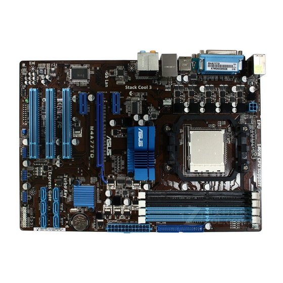
1.5.3Motherboard layout
KB_USB56
SPDIF_O
LPT
COM1
USB34
LAN1_USB12
AUDIO
RTL 8112L
I/O
Super
VIA
VT1708S
AAFP


|
1 |
2 |
3 |
4 |
1 |
||||
|
21.3cm(8.4in) |
||||||||
|
ATX12V |
CHA_FAN |
|||||||
|
AM3 |
module) |
module) |
module) |
module) |
||||
|
SOCKET |
(64bit,240-pin |
(64bit,240-pin |
(64bit,240-pin |
(64bit,240-pin |
||||
|
PRI_IDE |
||||||||
|
CPUFAN |
DIMM A2 |
DIMM B2 |
DIMM A1 |
DIMM B1 |
||||
|
DDR3 |
DDR3 |
DDR3 |
DDR3 |
5 |
||||
|
ICS |
770 |
30.5cm(12.0in) |
||||||
|
AMD® |
||||||||
|
9LPRS485 |
||||||||
|
PCIEX1_1 |
EATXPWR |
2 |
||||||
|
PCIEX16 |
||||||||
|
M4A77TD |
AMD® |
|||||||
|
PCIEX1_2 |
||||||||
|
SB710 |
||||||||
|
Lithium Cell |
||||||||
|
CMOS Power |
||||||||
|
PCI1 |
||||||||
|
8Mb |
||||||||
|
BIOS |
||||||||
|
PCI2 |
SATA1 |
SATA2 |
SATA3 |
6 |
||||
|
SATA4 |
SATA5 |
SATA6 |
||||||
|
PCI3 |
||||||||
|
SB_PWR |
USB78 |
USB1112 |
USB910 |
PANEL |
7 |
|||
|
CLRTC |
||||||||
|
SPDIF_OUT |
|
12 |
11 |
10 |
9 |
8 |
1.5.4Layout contents
|
Connectors/Jumpers/Slots/LED |
Page |
Connectors/Jumpers/Slots/LED |
Page |
||
|
1. |
CPU and chassis fan connectors |
1-27 |
7. |
System panel connector (20-8 pin PANEL) |
1-24 |
|
(4-pin CPU_FAN and 3-pin CHA_FAN) |
|||||
|
2. |
ATX power connectors (24-pin EATXPWR, 4-pin ATX12V) |
1-21 |
8. |
USB connectors (10-1 pin USB78, USB910, |
1-25 |
|
USB1112) |
|||||
|
3. |
CPU Socket AM3 |
1-8 |
9. |
Clear RTC RAM (3-pin CLRTC) |
1-18 |
|
4. |
DDR3 DIMM slots |
1-11 |
10. |
Onboard power LED (SB_PWR) |
1-5 |
|
5. |
IDE connector (40-1 pin PRI_IDE) |
1-22 |
11. |
Digital audio connector (4-1 pin SPDIF_OUT) |
1-26 |
|
6. |
SATA connectors (7-pin SATA1, SATA2, SATA3, SATA4, |
1-23 |
12. |
Front panel audio connector (10-1 pin AAFP) |
1-26 |
|
SATA5, and SATA6) |

1.6Central Processing Unit (CPU)
This motherboard comes with an AM3 socket designed for Phenom™ II / Athlon™ II / Sempron™ 100 series processors.
The AM3 socket has a different pinout from the AM2+/AM2 socket. Ensure that you use a CPU designed for the AM3 socket. The CPU fits in only one correct orientation. DO NOT force the CPU into the socket to prevent bending the pins and damaging the CPU!
1.6.1Installing the CPU
To install a CPU:
1.Locate the CPU socket on the motherboard.
M4A77TD
|
M4A77TD CPU socket AM3 |
|||||||||||||||
|
2. Press the lever sideways to unlock the |
Socket lever |
||||||||||||||
|
socket, then lift it up to a 90°-100° angle. |
Ensure that the socket lever is lifted up to a 90°-100° angle; otherwise, the CPU will not fit in completely.
3.Position the CPU above the socket such that the CPU corner with the gold triangle matches the socket corner with a small triangle.
4. Carefully insert the CPU into the socket until it fits in place.
The CPU fits only in one correct orientation.
DO NOT force the CPU into the socket to prevent bending the pins and damaging the CPU!
Small triangle
Gold triangle
|
1-8 |
Chapter 1: Product introduction |