Руководства пользователя
Версия T4204
1.97 MB
Motherboard Installation Guide (Traditional Chinese)
Версия C4204
1.83 MB
Motherboard Installation Guide (Simplified Chinese)
Версия QJ4204
1.68 MB
Motherboard Installation Guide (Japanese)
Версия QG4204
1.6 MB
Motherboard Installation Guide (German)
Версия QF4204
1.59 MB
Motherboard Installation Guide (French)
Версия Q4204
43.39 MB
Motherboard Installation Guide (Multiple Languages)
Версия T2831
5.8 MB
P5B user’s manual(Traditional Chinese)
Версия C2831
5.69 MB
P5B user’s manual(Simplified Chinese)
Версия E2620
2.95 MB
P5B User Manual for English Edition (E2620)
Версия T2927
2.25 MB
Telesky Traditional Chinese User’s manual T2927
Версия E2927
3.55 MB
Telesky English User’s manual E2927
Версия t2620
3.1 MB
P5B User’s Manual for Traditional Chinese Edtion(T2620)
Версия c2620
2.91 MB
P5B User’s Manual for Simplified Chinese Edtion (C2620)
Версия G2620
2.65 MB
P5B User’s Manual for German Edtion(G2620)
Версия J2620
3.86 MB
P5B User’s Manual for Japanese Edtion(J2620)
Версия F2620
3.98 MB
P5B User’s Manual for French Edtion(F2620)
Версия 1.0a
10.5 MB
JMicro JMB363 RAID User Guide
JMicro RAID AP Utility User Guide
JMicro RAID BIOS User Guide
Версия T2437
2.57 MB
Motherboard DIY Troubleshooting Guide (Traditional Chinese version)
Краткое содержание страницы № 1
P5B Premium
Series
Motherboard
Краткое содержание страницы № 2
E3006 Second Edition V2 January 2007 Copyright © 2007 ASUSTeK COMPUTER INC. All Rights Reserved. No part of this manual, including the products and software described in it, may be reproduced, transmitted, transcribed, stored in a retrieval system, or translated into any language in any form or by any means, except documentation kept by the purchaser for backup purposes, without the express written permission of ASUSTeK COMPUTER INC. (“ASUS”). Product warranty or service will not be extended
Краткое содержание страницы № 3
Contents Notices ………………………………………………………………………………………….. vii Safety information ………………………………………………………………………… viii About this guide …………………………………………………………………………….. ix P5B Premium Series specifications summary ………………………………….. xi Chapter 1: Product introduction 1.1 Welcome! …………………
Краткое содержание страницы № 4
Contents 2.6 Jumper ……………………………………………………………………………. 2-23 2.7 Connectors ……………………………………………………………………… 2-24 2.7.1 Rear panel connectors ………………………………………….. 2-24 2.7.2 Internal connectors ………………………………………………. 2-27 2.7.3 Installing the optional fan ………………………………………. 2-38 Chapter 3: Powering up 3.1
Краткое содержание страницы № 5
Contents 4.4 Advanced menu ………………………………………………………………. 4-16 4.4.1 JumperFree Configuration …………………………………….. 4-16 4.4.2 LAN Cable Status ………………………………………………… 4-19 4.4.3 USB Configuration ……………………………………………….. 4-19 4.4.4 TPM Configuration ……………………………………………….. 4-21 4.4.5 CPU Configuration ………………………….
Краткое содержание страницы № 6
Contents 5.3.2 AI NET2 ……………………………………………………………….5-11 5.3.3 PC Probe II …………………………………………………………. 5-12 5.3.4 ASUS AI Suite ……………………………………………………… 5-18 5.3.5 ASUS AI Gear ……………………………………………………… 5-20 5.3.6 ASUS AI Nap ………………………………………………………. 5-21 5.3.7 ASUS AI N.O.S. …………………
Краткое содержание страницы № 7
Notices Federal Communications Commission Statement This device complies with Part 15 of the FCC Rules. Operation is subject to the following two conditions: • This device may not cause harmful interference, and • This device must accept any interference received including interference that may cause undesired operation. This equipment has been tested and found to comply with the limits for a Class B digital device, pursuant to Part 15 of the FCC Rules. These limits are designed to provide r
Краткое содержание страницы № 8
Safety information Electrical safety • To prevent electrical shock hazard, disconnect the power cable from the electrical outlet before relocating the system. • When adding or removing devices to or from the system, ensure that the power cables for the devices are unplugged before the signal cables are connected. If possible, disconnect all power cables from the existing system before you add a device. • Before connecting or removing signal cables from the motherboard, ensure that all power
Краткое содержание страницы № 9
About this guide This user guide contains the information you need when installing and configuring the motherboard. How this guide is organized This guide contains the following parts: • Chapter 1: Product introduction This chapter describes the features of the motherboard and the new technology it supports. • Chapter 2: Hardware information This chapter lists the hardware setup procedures that you have to perform when installing system components. It includes description of the switches, ju
Краткое содержание страницы № 10
Conventions used in this guide To make sure that you perform certain tasks properly, take note of the following symbols used throughout this manual. DANGER/WARNING: Information to prevent injury to yourself when trying to complete a task. CAUTION: Information to prevent damage to the components when trying to complete a task. IMPORTANT: Instructions that you MUST follow to complete a task. NOTE: Tips and additional information to help you complete a task. Typography Bold
Краткое содержание страницы № 11
P5B Premium Series specifications summary ® CPU LGA775 socket for Intel Core™2 Quad / ® Core™2 Extreme / Core™2 Duo / Pentium Extreme / ® ® ® Pentium D / Pentium 4 / Celeron D Processors ® Compatible with Intel 05B/05A/06 processors ® Intel Hyper-Threading Technology ready * Refer to www.asus.com for Intel CPU support list ® ® Chipset Intel P965 / ICH8R with Intel Fast Memory Access Technology System Bus 1066 / 800 / 533 MHz Memory 4 x DIMM, max. 8GB, DDR2 800 / 667 / 533 MHz, non-E
Краткое содержание страницы № 12
P5B Premium Series specifications summary ASUS AI Lifestyle ASUS Quiet Thermal Solution: Unique features — ASUS AI Gear — ASUS AI Nap — ASUS 8-Phase Power Design — ASUS Fanless Design: Heat-pipe solution — ASUS Fanless Design: Stack Cool 2 — ASUS Q-Fan 2 — ASUS Optional Fan for Water-cooling or Passive- Cooling only ASUS Crystal Sound: — ASUS Noise Filter — ASUS Array Mic ASUS EZ DIY: — ASUS Q-Connector — ASUS O.C. Profile — ASUS CrashFree BIOS 3 — ASUS EZ Flash 2 — AS
Краткое содержание страницы № 13
P5B Premium Series specifications summary Internal I/O Connectors 2 x USB connectors support additional 4 USB ports 1 x Floppy disk drive connector 1 x IDE connector 1 x TPM connector 7 x SATA connectors 1 x CPU Fan connector 3 x Chassis Fan connector 1 x Power Fan connector 1 x IEEE1394a connector Front panel audio connector 1 x S/PDIF Out Header Chassis Intrusion connector CD audio in 24-pin ATX Power connector 2 x 4-pin ATX 12V Power connector System Panel BIOS Features 8 Mb Fl
Краткое содержание страницы № 14
xiv
Краткое содержание страницы № 15
This chapter describes the motherboard features and the new technologies it supports. Product 1 introduction
Краткое содержание страницы № 16
Chapter summary 1 1.1 Welcome! ………………………………………………………………………….. 1-1 1.2 Package contents ………………………………………………………………. 1-1 1.3 Special features …………………………………………………………………. 1-2 ASUS P5B Premium Series
Краткое содержание страницы № 17
1.1 Welcome! ® Thank you for buying an ASUS P5B Premium Series motherboard! The motherboard delivers a host of new features and latest technologies, making it another standout in the long line of ASUS quality motherboards! Before you start installing the motherboard, and hardware devices on it, check the items in your package with the list below. 1.2 Package contents Check your motherboard package for the following items. Motherboard ASUS P5B Premium Series I/O modules 1 x Multi-function modu
Краткое содержание страницы № 18
1.3 Special features 1.3.1 Product highlights Green ASUS This motherboard and its packaging comply with the European Union’s Restriction on the use of Hazardous Substances (RoHS). This is in line with the ASUS vision of creating environment-friendly and recyclable products/packaging to safeguard consumers’ health while minimizing the impact on the environment. ® Intel Quad-core Processor Ready ® This motherboard supports the latest Intel Quad-core processors in the LGA775 package. It is
Краткое содержание страницы № 19
Serial ATA 3.0 Gb/s technology and SATA-On-The-Go This motherboard supports the next-generation hard drives based on the Serial ATA (SATA) 3Gb/s storage specification, delivering enhanced scalability and doubling the bus bandwidth for high-speed data retrieval and saves. The external SATA port located at the back I/O provides smart setup and hot-plug functions. Easily backup photos, videos and other entertainment contents to external devices. See pages 2-25, and 2-28 for details. Dual
Краткое содержание страницы № 20
1.3.2 ASUS AI Lifestyle unique features ScreenDUO (Vista Edition only) The ScreenDUO provides a second display panel to enable you to conveniently view important information without having to start up your PC. The ScreenDUO synchronizes information from the PC or websites, displays RSS messages, meeting schedules and other important information. This saves you the time and the hassle to turn on your PC each time you want to view vital information. AI Remote (Vista Edition only) The revolu
(скачивание инструкции бесплатно)
Формат файла: PDF
Доступность: Бесплатно как и все руководства на сайте. Без регистрации и SMS.
Дополнительно: Чтение инструкции онлайн

Quick Start Guide
First Edition V1 Published June 2006
Copyright © 2006 ASUSTeK COMPUTER INC. All Rights Reserved.
15G0636861K0
U2618
P5B Deluxe
Français
Deutsch
Italiano
Español
Русский
Português
Polski
Česky
Magyar
Български
Română
Srpski
Страница:
(1 из 50)
навигация

1

2

3

4

5

6

7

8

9

10

11

12

13

14

15

16

17

18

19

20

21

22

23

24

25

26

27

28

29

30

31

32

33

34

35

36

37

38

39

40

41

42

43

44

45

46

47

48

49

50
Оглавление инструкции
- Страница 1 из 51
U2618 P5B Deluxe Quick Start Guide Français Deutsch Italiano Español Русский Português Polski Česky Magyar Български Română Srpski First Edition V1 Published June 2006 Copyright © 2006 ASUSTeK COMPUTER INC. All Rights Reserved. 15G0636861K0 - Страница 2 из 51
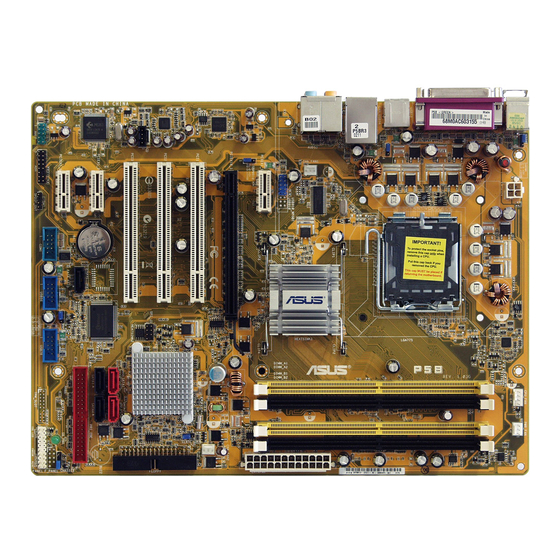
1. Schéma de la Carte Mère CPU_FAN Intel® P965 USB910 PWR_FAN CHA_FAN4 CR2032 3V Lithium Cell CMOS Power CHA_FAN5 PCI1 PLED CLRTC PCI2 88E8001 CD AAFP TSB43AB22A 2. SATA5 IE1394_2 PCI3 ADH 8Mb BIOS SATA2 IDE_LED SATA1 SATA3 SATA6 USB56 USB78 SATA4 CHA_FAN1 Reset Ground PCIEX16_2 PCIEX1_1 SPEAKER - Страница 3 из 51
• • Pour éviter d’endommager les broches du socle, n’enlevez le capuchon PnP que si vous installez un processeur. Veuillez conserver le capuchon pour le renvoi du produit. La garantie du produit ne couvre pas des dommages liés aux broches du support. Français • 2. Soulevez le levier de chargement - Страница 4 из 51
Français • Vous pouvez installer des modules mémoire de tailles variables dans les canaux mémoire A et B. Le système mappe automatiquement la mémoire totale du canal de la plus petite taille pour une configuration double canal. Tout excès de mémoire du canal de plus grande taille est alors mappé - Страница 5 из 51
4. Informations du BIOS Français La ROM Flash sur la carte mère contient un BIOS. Vous pouvez mettre à jour les informations du BIOS ou configurer ses paramètres en utilisant l’utilitaire de Setup du BIOS. Les écrans BIOS comprennent les clés de navigation et une courte aide en ligne pour vous - Страница 6 из 51
1. Motherboard-Layout PS/2KBMS T: Mouse B: Keyboard CPU_FAN Intel® P965 USB910 PWR_FAN CHA_FAN4 CHA_FAN5 PLED CLRTC PCI2 88E8001 CD AAFP ADH 2. TSB43AB22A SATA5 IE1394_2 SATA2 IDE_LED SATA1 SATA3 SATA6 USB56 USB78 SATA4 CHA_FAN1 RESET PWRSW CHA_FAN3 PANEL Reset Ground 8Mb BIOS IDE_LED+ IDE_LED- - Страница 7 из 51
• Um Schäden an den Sockelpolen zu vermeiden, entfernen Sie bitte die PnP-Kappe nicht vor dem Beginn der CPU-Installation. • Bitte bewahren Sie die Abdeckung für den Fall einer Produktrückgabe auf. • Die Garantie des Produkts deckt nicht die Schäden an Sockelpolen. Heben Sie den Ladehebel in - Страница 8 из 51
• Sie können in Kanal A und Kanal B verschiedene Speichergrößen installieren. Das System bildet die gesamte Größe des kleineren Kanals für die Dual-Channel-Konfiguration ab. Überschüssiger Speicher des größeren Kanals wird dann für die Single-ChannelVerwendung abgebildet. Deutsch • Installieren Sie - Страница 9 из 51
4. BIOS-Informationen Das BIOS ist in einem Flash-ROM auf dem Motherboard gespeichert. Sie können mit Hilfe des BIOS-Setupprogramms die BIOS-Informationen aktualisieren oder die Parameter konfigurieren. Auf den BIOS-Seiten finden Sie Navigationstasten und eine kurze Online-Hilfe. Laden Sie bitte - Страница 10 из 51
1. Diagramma disposizione scheda madre PS/2KBMS T: Mouse B: Keyboard CPU_FAN Intel® P965 USB910 PWR_FAN CHA_FAN4 CHA_FAN5 PLED CLRTC 88E8001 CD AAFP TSB43AB22A 2. SATA5 IE1394_2 PCI3 ADH 8Mb BIOS SATA2 IDE_LED SATA1 SATA3 SATA6 USB56 USB78 SATA4 CHA_FAN1 RESET PWRSW CHA_FAN3 PANEL Reset Ground - Страница 11 из 51
• Per evitare di danneggiare i pin, non rimuovere la copertura PnP salvo si stia installando una CPU. • Conservare il cappuccio per eventuali restituzioni del prodotto. • La garanzia del prodotto non copre i danni ai pin della presa. 3. 4. 5. 3. Sollevare la levetta di carico nella direzione - Страница 12 из 51
• Nel canale A e nel canale B, e’ possibile installare una memoria di dimensioni variabili. Per la configurazione a doppio canale, il sistema esegue una mappatura delle dimensioni complessive del canale di dimensioni inferiori. La memoria in eccesso presente nel canale di maggiori dimensioni è - Страница 13 из 51
4. Informazioni sul BIOS La Flash ROM sulla scheda madre contiene il BIOS. È possibile aggiornare le informazioni del BIOS, o configurare i parametri utilizzando l’utilità di configurazione BIOS Setup. La schermata BIOS include tasti di navigazione ed una concisa guida in linea. Se si riscontrano - Страница 14 из 51
1. Distribución de la placa base PS/2KBMS T: Mouse B: Keyboard CPU_FAN Intel® P965 USB910 PWR_FAN Normal (Default) CHA_FAN4 CHA_FAN5 PLED CLRTC PCI2 88E8001 CD AAFP ADH Español 2. TSB43AB22A SATA5 IE1394_2 SATA2 IDE_LED SATA1 SATA3 SATA6 USB56 USB78 SATA4 CHA_FAN1 RESET PWRSW CHA_FAN3 PANEL Reset - Страница 15 из 51
• Para evitar daños en los contactos del zócalo, no retire la tapa PnP, a menos que se esté instalando una CPU. • Conserve la tapa en caso de devolución del producto. • La garantía del producto no cubre daños producidos en los contactos del zócalo. 2. 3. 4. 5. 3. Levante la palanca de carga en la - Страница 16 из 51
• Puede instalar memorias de diferentes tamaños en los canales A y B. El sistema mapea el tamaño total del canal de menor tamaño para configuraciones de canal dual. Cualquier exceso de memoria en el canal de mayor tamaño será mapeado en operaciones de canal simple. • Instale siempre DIMM con la - Страница 17 из 51
4. Información de la BIOS La Flash ROM de la placa base contiene la BIOS. Puede actualizar la información de la BIOS o configurar los parámetros utilizando la utilidad Configuración de la BIOS. Las pantallas de la BIOS incluyen teclas de navegación y una breve ayuda en línea para guiarle. Si - Страница 18 из 51
1. Схема системной платы PS/2KBMS T: Mouse B: Keyboard Intel® P965 PWR_FAN CHA_FAN4 CHA_FAN5 PLED CLRTC PCI2 88E8001 CD AAFP ADH 2. TSB43AB22A SATA5 IE1394_2 SATA2 IDE_LED SATA1 SATA3 SATA6 USB56 USB78 SATA4 CHA_FAN1 RESET PWRSW CHA_FAN3 PANEL Reset Ground 8Mb BIOS IDE_LED+ IDE_LED- PCIEX16_2 PCI3 - Страница 19 из 51
• Для предотвращения повреждения контактов разъема не удаляйте крышку PnP до начала установки ЦПУ. • Для возврата товара сохраняйте упаковку. • Гарантия на товар не распространяется на случай повреждения контактов разъема. 2. Поднимите рычак в направлении, указанном стрелкой, до угла 135°. 3. - Страница 20 из 51
• Вы можете установить различный объем памяти в слоты канала A и канала B. Надо учитывать, что для двухканальной конфигурации система будет отображать общий объем памяти, ориентируясь на канал с меньшим объемом установленной памяти. Полный объем установленной памяти в таком случае будет - Страница 21 из 51
4. Базовая система ввода/вывода (BIOS) BIOS записан в микросхеме энергонезависимой памяти, находящейся на системной плате. Используя утилиту настройки BIOS можно настроить или обновить BIOS. Экраны BIOS содержат кнопки навигации и краткую справку. Если после изменения настроек BIOS система стала - Страница 22 из 51
1. Disposição da placa-principal PS/2KBMS T: Mouse B: Keyboard CPU_FAN Intel® P965 USB910 PWR_FAN CHA_FAN4 CHA_FAN5 PLED CLRTC PCI2 88E8001 CD AAFP ADH 2. TSB43AB22A SATA5 IE1394_2 SATA2 IDE_LED SATA1 SATA3 SATA6 USB56 USB78 SATA4 CHA_FAN1 RESET PWRSW CHA_FAN3 PANEL Reset Ground 8Mb BIOS IDE_LED+ - Страница 23 из 51
• Para evitar danificar os pinos do socket, não remova a tampa PnP a não ser que esteja a instalar uma CPU. • Guarde a tampa, caso seja necessário devolver o produto. • A garantia do produto não cobre danos ao nível dos pinos do socket. 2. 3. 4. 5. 3. Levante a alavanca na direcção indicada pela - Страница 24 из 51
• Pode instalar memórias de vários tamanhos no canal A e no canal B. O sistema faz o mapeamento do tamanho total do canal de menor capacidade para a configuração de canal duplo. Qualquer memória excedente do canal de maior capacidade é mapeada para a configuração de canal único. • Instale sempre - Страница 25 из 51
4. Informação da BIOS A memória ROM Flash existente na placa-principal contém a BIOS. Pode actualizar a informação da BIOS ou configurar os seus parâmetros utilizando o utilitário de configuração da BIOS. Os ecrãs da BIOS incluem teclas de navegação e uma breve ajuda online que lhe servirão de - Страница 26 из 51
1. Plan płyty głównej Intel® P965 PWR_FAN Normal (Default) CHA_FAN4 CR2032 3V Lithium Cell CMOS Power JMicron JMB363 CHA_FAN5 PCI1 PLED CLRTC PCI2 88E8001 CD AAFP TSB43AB22A 2. SATA5 IE1394_2 PCI3 ADH SATA2 SATA3 SATA6 USB56 USB78 SATA4 CHA_FAN1 PWRSW CHA_FAN3 PANEL RESET IDE_LED SATA1 Reset Ground - Страница 27 из 51
• Aby uniknąć uszkodzenia szpilek gniazda, nie należy zdejmować pokrywki PnP, aż do zainstalowania procesora. Polski • Należy zachować pokrywki na wypadek zwrotu produktu. • Gwarancja produktu nie obejmuje uszkodzeń szpilek gniazda. 2. 3. 4. 5. 3. Unieś dźwignię ładowania w kierunku wskazanym - Страница 28 из 51
Polski • W kanale A i kanale B można instalować pamięci o różnych rozmiarach. W konfiguracji dwu-kanałowej, system odwzorowuje całkowity rozmiar kanału o mniejszym rozmiarze. Nadmierna pamięć z kanału o większym rozmiarze jest następnie odwzorowywana dla operacji jedno-kanałowej. • Należy zawsze - Страница 29 из 51
4. Informacje BIOS Polski Moduł Flash ROM na płycie zawiera BIOS. Możesz uaktualnić informacje BIOS lub skonfigurować parametry używając narzędzia do konfiguracji BIOS. Ekran BIOS zawiera przyciski nawigacyjne i krótką pomoc online, aby Cię poprowadzić. Jeśli napotkasz problemy systemowe lub gdy - Страница 30 из 51
1. Rozvržení základní desky PS/2KBMS T: Mouse B: Keyboard Intel® P965 PWR_FAN Normal (Default) CHA_FAN4 CHA_FAN5 PLED CLRTC PCI2 88E8001 CD AAFP ADH 2. TSB43AB22A SATA5 IE1394_2 SATA2 SATA3 USB56 USB78 SATA4 CHA_FAN1 Reset Ground PWRSW CHA_FAN3 PANEL RESET IDE_LED SATA1 SATA6 PWR Ground 8Mb BIOS - Страница 31 из 51
• Abyste zabránili poškození pinů patice, nesundávejte ochrannou záslepku (PnP cap) dokud nebudete instalovat procesor. • Ochrannou záslepku zachovejte pro případné vrácení produktu. • Záruka na desku se nevztahuje na poškození pinů patice. Nadzvedněte zajišťovací páčku ve směru šipky do úhlu 135º. - Страница 32 из 51
• Můžete nainstalovat různé velikosti paměti do kanálu A a do kanálu B. Systém namapuje celkovou velikost menšího kanálu pro dvoukanálovou konfiguraci. Přebývající paměť z většího kanálu je potom namapována pro jednokanálový provoz. • Vždy instalujte moduly DIMM se stejnou čekací dobou CAS. Pro - Страница 33 из 51
4. Informace o BIOSu Pamět’ Flash ROM na základní desce uchovává informace o možnostech nastavení (Setup utility). Můžete aktualizovat informace v BIOSu nebo konfigurovat parametry pomocí BIOS Setup utility. Obrazovky BIOS používjí k ovládání navigační klávesy a online pomoc. Pokud budete mít - Страница 34 из 51
1. Az alaplap felépítése PS/2KBMS T: Mouse B: Keyboard CPU_FAN Intel® P965 USB910 PWR_FAN Normal (Default) CHA_FAN4 CHA_FAN5 PLED 88E8001 CD AAFP 2. SATA5 IE1394_2 PCI3 ADH 8Mb BIOS TSB43AB22A SATA2 IDE_LED SATA1 SATA3 SATA6 USB56 USB78 SATA4 CHA_FAN1 RESET PWRSW CHA_FAN3 PANEL Reset Ground - Страница 35 из 51
• A foglalat védelme érdekében ne távolítsa el a foglalat védősapkáját, csak közvetlenül a processzor behelyezése előtt. • A foglalat védősapkáját tartsa meg későbbi felhasználásra, ne dobja el. • A foglalat tűinek sérüléseire nem terjed ki a termékgarancia. Hajtsa fel 135°-os szögben a - Страница 36 из 51
• Különböző méretű memóriamodulokat szerelhet be a Channel A és a Channel B jelű foglalatokba. A rendszer a kisebb méretű csatorna teljes kapacitását kétcsatornás konfigurációba állítja. A nagyobb méretű csatorna ezen felüli memóriakapacitását pedig a rendszer egycsatornás üzemmódba állítja. • - Страница 37 из 51
4. BIOS információk Az alaplap BIOS-át az alaplapon található Flash ROM chip tartalmazza. A BIOS-jellemzőket a BIOS Setup segédprogramon keresztül állíthatja. A BIOS Setup beépített súgóval (Help) is rendelkezik. Amennyiben a rendszer instabillá válna, vagy más rendszerproblémákat észlel a BIOS - Страница 38 из 51
1. Схема на дънната платка PS/2KBMS T: Mouse B: Keyboard Intel® P965 PWR_FAN CHA_FAN4 CHA_FAN5 PCI1 PLED CLRTC PCI2 88E8001 CD ADH Български 2. TSB43AB22A SATA5 IE1394_2 SATA2 IDE_LED SATA1 SATA3 SATA6 USB56 USB78 SATA4 CHA_FAN1 Reset Ground RESET PWRSW CHA_FAN3 PANEL PWR Ground Intel ICH8R 8Mb - Страница 39 из 51
• За да се предотврати деформация на щифтовете, не премахвайте PnP тапата, освен ако няма да инсталирате процесор. • Моля пазете тапата в случай че искате да върнете закупения продукт. • Гаранцията не покрива повреди на щифтовете. 2. 3. 4. 5. 3. Повдигнете лоста за зареждане по посока на стрелката - Страница 40 из 51
• В каналите А и В Вие може да инсталирате модули памет с различен обем. Система определя общия обем на канала с по-малко памет за двуканална конфигурация. Останалият обем от канала с повече памет се определя за едноканален режим. • Винаги инсталирайте DIMM модули с еднаква CAS задръжка. За - Страница 41 из 51
4. BIOS информация Можете да обновявате информацията на BIOS или да настройвате параметрите чрез използването на BIOS Setup. BIOS екраните съдържат навигационни клавиши и кратка онлайн помощ. В случай, че установите проблеми със системата или същата стане нестабилна след промяната на настройките, - Страница 42 из 51
1. Schema plăcii de bază PS/2KBMS T: Mouse B: Keyboard Intel® P965 PWR_FAN CHA_FAN4 CHA_FAN5 PLED CLRTC PCI2 88E8001 CD AAFP ADH 2. TSB43AB22A SATA5 IE1394_2 SATA2 SATA3 USB56 USB78 SATA4 CHA_FAN1 PWRSW CHA_FAN3 PANEL RESET IDE_LED SATA1 SATA6 Reset Ground 8Mb BIOS IDE_LED+ IDE_LED- PCIEX16_2 PCI3 - Страница 43 из 51
• ��������������������������������������������������������������������� Pentru a împiedica deteriorarea contactelor soclului, nu îndepărtaţi capacul PnP decât dacă instalaţi CPU. • ���������������������������������������������������������� Vă rugăm să păstraţi capacul pentru returnarea produsului. - Страница 44 из 51
• Puteţi instala memorii cu diverse dimensiuni în Canalul A şi Canalul B. Sistemul identifică dimenisunea totală a canalului care are cea mai mică dimensiune pentru configurarea canalului dublu. Orice memorie excedentară a canalului care are cea mai mare dimensiune este apoi identificată pentru - Страница 45 из 51
4. Informaţii despre BIOS Memoria Flash ROM de pe placa de bază conţine BIOS-ul. Puteţi actualiza informaţia sau parametrii din BIOS folosind funcţia de instalare BIOS (BIOS Setup). Ecranele BIOS includ taste de navigaţie şi scurt ajutor on-line pentru a vă ghida. Dacă întâlniţi probleme de sistem, - Страница 46 из 51
1. Izgled matične ploče PS/2KBMS T: Mouse B: Keyboard Intel® P965 PWR_FAN Normal (Default) CHA_FAN4 CHA_FAN5 PLED CLRTC PCI2 88E8001 CD AAFP ADH 2. SATA5 IE1394_2 SATA2 SATA3 USB56 USB78 SATA4 CHA_FAN1 PWRSW CHA_FAN3 PANEL RESET IDE_LED SATA1 SATA6 Reset Ground 8Mb BIOS TSB43AB22A IDE_LED+ IDE_LED- - Страница 47 из 51
l Da bi ste zaštitili konektore na podnožju nemojte uklanjati poklopac osim ako ne postavljate procesor. Zadržite poklopac u slučaju da želite da vratite proizvod. l Garancija npokriva oštećena na konektorima podnožja procesora. l 2. Podignite ručicu u pravcu strelice do ugla od 135 stepeni. 3. - Страница 48 из 51
• Možete da instalirate memoriju različite veličine u Kanale A i B. Sistem mapira ukupnu veličinu manjeg kanala za konfiguraciju sa duplim kanalima. Bilo kakva preostala memorija sa višeg kanala se tada mapira za rad sa samo jednim kanalom. • Uvek koristite memorije sa jednakim CAS vrednostima, za - Страница 49 из 51
4. BIOS Flash ROM na matičnoj ploči sadrži BIOS. Parametre BIOS-a možete promeniti pomoću uslužnog programa. Ekrani BIOS-a podržavaju navigaciju putem tastature i kratka objašnjenja svakog od parametara. Ukoliko vaš sistem ima probleme, ili je posta nestabilan posle promena parametara, odaberite - Страница 50 из 51
www.asus.com - Страница 51 из 51
-
Драйверы
50
-
Инструкции по эксплуатации
16
Языки:

ASUS P5B инструкция по эксплуатации
(56 страниц)
- Языки:Английский
-
Тип:
PDF -
Размер:
3.62 MB -
Описание:
Telesky English User’s manual E2927
Просмотр

ASUS P5B инструкция по эксплуатации
(140 страниц)
- Языки:Английский
-
Тип:
PDF -
Размер:
2.95 MB -
Описание:
P5B User Manual for English Edition (E2620)
Просмотр

ASUS P5B инструкция по эксплуатации
(26 страниц)
- Языки:Английский
-
Тип:
ZIP -
Размер:
10.5 MB -
Описание:
JMicro JMB363 RAID User Guide
JMicro RAID AP Utility User Guide
JMicro RAID BIOS User Guide
Просмотр

ASUS P5B инструкция по эксплуатации
(40 страниц)
- Языки:Молдавский, Немецкий
-
Тип:
PDF -
Размер:
1.65 MB -
Описание:
Motherboard Installation Guide (German)
Motherboard Installation Guide (German)
Просмотр

ASUS P5B инструкция по эксплуатации
(46 страниц)
- Языки:Китайский
-
Тип:
PDF -
Размер:
2.31 MB -
Описание:
Telesky Traditional Chinese User’s manual T2927
Просмотр

ASUS P5B инструкция по эксплуатации
(140 страниц)
- Языки:Китайский
-
Тип:
PDF -
Размер:
5.81 MB -
Описание:
P5B user’s manual(Simplified Chinese)
Просмотр

ASUS P5B инструкция по эксплуатации
(44 страницы)
- Языки:Китайский, Молдавский
-
Тип:
PDF -
Размер:
1.88 MB -
Описание:
Motherboard Installation Guide (Simplified Chinese)
Просмотр

ASUS P5B инструкция по эксплуатации
(44 страницы)
- Языки:Китайский, Молдавский
-
Тип:
PDF -
Размер:
2.02 MB -
Описание:
Motherboard Installation Guide (Traditional Chinese)
Просмотр

ASUS P5B инструкция по эксплуатации
(140 страниц)
- Языки:Китайский
-
Тип:
PDF -
Размер:
5.92 MB -
Описание:
P5B user’s manual(Traditional Chinese)
Просмотр

ASUS P5B инструкция по эксплуатации
(140 страниц)
- Языки:Немецкий
-
Тип:
PDF -
Размер:
2.65 MB -
Описание:
P5B User’s Manual for German Edtion(G2620)
Просмотр

ASUS P5B инструкция по эксплуатации
(140 страниц)
- Языки:Японский
-
Тип:
PDF -
Размер:
3.86 MB -
Описание:
P5B User’s Manual for Japanese Edtion(J2620)
Просмотр

ASUS P5B инструкция по эксплуатации
(140 страниц)
- Языки:Французский
-
Тип:
PDF -
Размер:
3.98 MB -
Описание:
P5B User’s Manual for French Edtion(F2620)
Просмотр

ASUS P5B инструкция по эксплуатации
(8 страниц)
- Языки:Китайский, Молдавский
-
Тип:
PDF -
Размер:
2.67 MB -
Описание:
Motherboard DIY Troubleshooting Guide (Traditional Chinese version)
Просмотр

ASUS P5B инструкция по эксплуатации
(40 страниц)
- Языки:Молдавский, Японский
-
Тип:
PDF -
Размер:
1.73 MB -
Описание:
Motherboard Installation Guide (Japanese)
Просмотр

ASUS P5B инструкция по эксплуатации
(40 страниц)
- Языки:Молдавский, Французский
-
Тип:
PDF -
Размер:
1.64 MB -
Описание:
Motherboard Installation Guide (French)
Просмотр

ASUS P5B инструкция по эксплуатации
(721 страница)
- Языки:Молдавский
-
Тип:
PDF -
Размер:
43.88 MB -
Описание:
Motherboard Installation Guide (Multiple Languages)
Просмотр
На NoDevice можно скачать инструкцию по эксплуатации для ASUS P5B. Руководство пользователя необходимо для ознакомления с правилами установки и эксплуатации ASUS P5B. Инструкции по использованию помогут правильно настроить ASUS P5B, исправить ошибки и выявить неполадки.
-
Contents
-
Table of Contents
-
Bookmarks
Quick Links
Related Manuals for Asus P5B
Summary of Contents for Asus P5B
-
Page 2
Product warranty or service will not be extended if: (1) the product is repaired, modified or altered, unless such repair, modification of alteration is authorized in writing by ASUS; or (2) the serial number of the product is defaced or missing. -
Page 3: Table Of Contents
Contents Notices ………………….vii Safety information ………………viii About this guide ………………ix P5B specifications summary …………..xi Chapter 1: Product introduction Welcome! ………………1-1 Package contents …………….. 1-1 Special features …………….1-2 1.3.1 Product highlights …………1-2 1.3.2 ASUS AI Lifestyle features ……….1-3 1.3.3…
-
Page 4
Chapter 4: BIOS setup Managing and updating your BIOS ……….4-1 4.1.1 Creating a bootable floppy disk ……..4-1 4.1.2 ASUS EZ Flash 2 utility ……….. 4-2 4.1.3 AFUDOS utility …………..4-3 4.1.4 ASUS CrashFree BIOS 3 utility ……..4-5 4.1.5… -
Page 5
Boot Settings Configuration ……… 4-29 4.6.3 Security …………….. 4-30 Tools menu …………….. 4-32 4.7.1 ASUS EZ Flash 2 …………4-32 4.7.2 ASUS O.C. Profile …………4-33 Exit menu ………………4-34 Chapter 5: Software support Installing an operating system ……….. 5-1 Support CD information ………….. -
Page 6
Contents 5.3.2 ASUS PC Probe II …………5-10 5.3.3 ASUS AI Suite …………… 5-16 5.3.4 ASUS AI Gear …………… 5-18 5.3.5 ASUS AI Nap …………..5-19 5.3.6 SoundMAX High Definition Audio utility ……. 5-20 ® RAID configurations …………..5-24 5.4.1 Installing Serial ATA hard disks …….. -
Page 7: Notices
Notices Federal Communications Commission Statement This device complies with Part 15 of the FCC Rules. Operation is subject to the following two conditions: • This device may not cause harmful interference, and • This device must accept any interference received including interference that may cause undesired operation.
-
Page 8: Safety Information
Safety information Electrical safety • To prevent electrical shock hazard, disconnect the power cable from the electrical outlet before relocating the system. • When adding or removing devices to or from the system, ensure that the power cables for the devices are unplugged before the signal cables are connected.
-
Page 9: About This Guide
Refer to the following sources for additional information and for product and software updates. ASUS websites The ASUS website provides updated information on ASUS hardware and software products. Refer to the ASUS contact information. Optional documentation Your product package may include optional documentation, such as warranty flyers, that may have been added by your dealer.
-
Page 10: Conventions Used In This Guide
Conventions used in this guide To make sure that you perform certain tasks properly, take note of the following symbols used throughout this manual. DANGER/WARNING: Information to prevent injury to yourself when trying to complete a task. CAUTION: Information to prevent damage to the components when trying to complete a task.
-
Page 11: P5B Specifications Summary
® ® ® processors Compatible with Intel 05B/05A and 06B processors ® Intel Hyper-Threading Technology ready ® * Refer to www.asus.com for Intel CPU support list ® Chipset Northbridge: Intel P965 with Intel Fast Memory Access ® ® Southbridge: Intel ICH8 ®…
-
Page 12
Intelligent overclocking tools: Overclocking features — AI NOS™ (Non-delay Overclocking System) — AI Overclocking (Intelligent CPU frequency tuner) — ASUS PEG Link (Automatically performance tuning for graphics card) — ASUS AI Booster utility Precision Tweaker: — vDIMM: 2-step DRAM voltage control — vCore: Adjustable CPU voltage at 6.25 mV… -
Page 13
P5B specifications summary BIOS features 8 Mb Flash ROM, AMI BIOS, PnP, DMI 2.0, WfM2.0, SM BIOS 2.3, ACPI 2.0a, ASUS EZ Flash 2, ASUS CrashFree BIOS 3 Manageability WfM 2.0, DMI 2.0, WOL by PME, WOR by PME, PXE… -
Page 15: Chapter 1: Product Introduction
This chapter describes the motherboard features and the new technologies it supports. Product introduction…
-
Page 16
Chapter summary Welcome! ………………1-1 Package contents …………….. 1-1 Special features …………….1-2 ASUS P5B… -
Page 17: Welcome
® The motherboard delivers a host of new features and latest technologies, making it another standout in the long line of ASUS quality motherboards! Before you start installing the motherboard, and hardware devices on it, check the items in your package with the list below.
-
Page 18: Special Features
Green ASUS This motherboard and its packaging comply with the European Union’s Restriction on the use of Hazardous Substances (RoHS). This is in line with the ASUS vision of creating environment-friendly and recyclable products/packaging to safeguard consumers’ health while minimizing the impact on the environment.
-
Page 19: Asus Ai Lifestyle Features
See page 4-22 for details. 1.3.2 ASUS AI Lifestyle features ASUS Quiet Thermal Solution ASUS Quiet Thermal solution makes system more stable and enhances the overclocking capability. AI Gear AI Gear provides four modes that adjust the CPU frequency and Vcore voltage minimizing system noise and power consumption.
-
Page 20: Asus Crystal Sound
ASUS EZ DIY ASUS EZ DIY feature collection provides you easy ways to install computer components, update the BIOS or back up your favorite settings. ASUS Q-Connector ASUS Q-Connector allows you to easily connect or disconnect the chassis front panel cables to the motherboard.
-
Page 21: Asus Special Features
1.3.4 ASUS Intelligent Overclocking features AI NOS™ (Non-Delay Overclocking System) The patented ASUS Non-delay Overclocking System™ (AI NOS™) technology auto-detects the CPU loading and dynamically overclocks the CPU speed when needed. Unlike other dynamic overclocking techniques, AI NOS™ reacts much faster to satisfy your need for speed.
-
Page 22
Chapter 1: Product introduction… -
Page 23: Chapter 2: Hardware Information
This chapter lists the hardware setup procedures that you have to perform when installing system components. It includes description of the jumpers and connectors on the motherboard. Hardware information…
-
Page 24: Chapter Summary
Chapter summary 2.1 Before you proceed …………..2-1 2.2 Motherboard overview …………..2-2 2.3 Central Processing Unit (CPU) ……….. 2-6 2.4 System memory …………….. 2-13 2.5 Expansion slots …………….2-17 2.6 Jumper ………………2-20 2.7 Connectors …………….. 2-22 ASUS P5B…
-
Page 25: Before You Proceed
ON, in sleep mode, or in soft-off mode. This is a reminder that you should shut down the system and unplug the power cable before removing or plugging in any motherboard component. The illustration below shows the location of the onboard LED. SB_PWR Standby Powered Power P5B Onboard LED ASUS P5B…
-
Page 26: Motherboard Overview
Motherboard overview Before you install the motherboard, study the configuration of your chassis to ensure that the motherboard fits into it. Make sure to unplug the power cord before installing or removing the motherboard. Failure to do so can cause you physical injury and damage motherboard components.
-
Page 27: Motherboard Layout
USB90 PCIEX_ PCIEX6_ RTL8B PCI Intel PCI2 ADI988A ICH8 SPI BIOS PCI SATA SATA2 SATA SATA Super I/O CR202 V PCIEX_2 JMB6 Lithium Cell CMOS Power SATA_RAID PRI_IDE PCIEX_ USBPW5678 CHASSIS SB_PWR COM USB56 USB78 AAFP SPDIF_OUT PANEL ASUS P5B…
-
Page 28: Layout Contents
2.2.4 Layout contents S lots Page DDR2 DIMM slots 2- PCI slots 2-9 PCI Express x slots 2-9 PCI Express x6 slot 2-9 Jumper Page . Clear RTC RAM (-pin CLRTC) 2-20 USB Device wake-up (-pin USBPW2, USBPW5678, USBPW90) 2-2 Keyboard power (-pin KBPWR) 2-2 Rear panel connectors Page…
-
Page 29
Serial port connector (0- pin COM) 2-29 0. Chassis intrusion connector (- pin CHASSIS) 2-0 . Front panel audio connector (0- pin AAFP) 2-0 2. ATX power connectors (2-pin EATXPWR, -pin EATX2V) 2- . System panel connector (20-8 pin PANEL) 2-2 ASUS P5B… -
Page 30: Central Processing Unit (Cpu)
ASUS will shoulder the cost of repair only if the damage is shipment/transit-related. • Keep the cap after installing the motherboard. ASUS will process Return Merchandise Authorization (RMA) requests only if the motherboard comes with the cap on the LGA775 socket.
-
Page 31: Installing The Cpu
Retention tab PnP cap Load lever This side of the socket box should face you. To prevent damage to the socket pins, do not remove the PnP cap unless you are installing a CPU. Lift the load lever in the direction of the arrow to a 5º angle. ASUS P5B…
-
Page 32
Lift the load plate with your thumb and forefinger to a 100º angle (A), then push the PnP cap from the load plate window to remove (B). Load plate Alignment key Position the CPU over the socket, making sure that the gold triangle is on the bottom-left corner of the socket then fit the socket alignment key into the… -
Page 33: Installing The Heatsink And Fan
CPU fan cable is closest to the CPU fan connector. Motherboard hole Fastener Narrow end of the groove Make sure to orient each fastener with the narrow end of the groove pointing outward. (The photo shows the groove shaded for emphasis.) ASUS P5B…
-
Page 34
Connect the CPU fan cable to the connector on the motherboard labeled CPU_FAN. CPU_FAN P5B CPU Fan Connector Do not forget to connect the CPU fan connector! Hardware monitoring errors can occur if you fail to plug this connector. 2-0… -
Page 35
Rotate each fastener counterclockwise. Pull up two fasteners at a time in a diagonal sequence to disengage the heatsink and fan assembly from the motherboard. Carefully remove the heatsink and fan assembly from the motherboard. ASUS P5B 2-… -
Page 36
Rotate each fastener clockwise to ensure correct orientation when reinstalling. Narrow end of the groove The narrow end of the groove should point outward after resetting. (The photo shows the groove shaded for emphasis.) Refer to the documentation in the boxed or stand-alone CPU fan package for detailed information on CPU fan installation. -
Page 37: System Memory
If you install Windows ® XP 2-bit operation system, a total memory of less than GB is recommended. • This motherboard does not support memory modules made up of 28 Mb chips or double sided x6 memory modules. ASUS P5B 2-…
-
Page 38
Notes on memory limitations • Due to chipset limitation, this motherboard can only support up to 8 GB on the operating systems listed below. You may install a maximum of 2 GB DIMMs on each slot, but only DDR2-5 and DDR2-667 2 GB density modules are available for this configuration. -
Page 39
Supports one pair of modules inserted into either the blue slots or the black slots as one pair of Dual‑channel memory configuration. Supports four modules inserted into both the blue and black slots as two pairs of Dual‑channel memory configuration. Visit the ASUS website (www.asus.com) for the latest QVL. ASUS P5B 2-5… -
Page 40: Installing A Dimm
2.4.3 Installing a DIMM Unplug the power supply before adding or removing DIMMs or other system components. Failure to do so can cause severe damage to both the motherboard and the components. To install a DIMM: DDR2 DIMM notch Unlock a DIMM socket by pressing the retaining clips outward.
-
Page 41: Expansion Slots
IRQ” or that the cards do not need IRQ assignments. Otherwise, conflicts will arise between the two PCI groups, making the system unstable and the card inoperable. Refer to the table on the next page for details. ASUS P5B 2-7…
-
Page 42: Interrupt Assignments
2.5.3 Interrupt assignments Standard interrupt assignments IRQ Priority Standard Function System Timer Keyboard Controller — Re-direct to IRQ#9 IRQ holder for PCI steering* Communications Port (COM)* IRQ holder for PCI steering* Floppy Disk Controller Printer Port (LPT)* System CMOS/Real Time Clock ACPI* SMBus Controller* IRQ holder for PCI steering* PS/2 Compatible Mouse Port* Numeric Data Processor…
-
Page 43: Pci Slots
PCI Express x slot. 2.5.6 PCI Express x16 slot This motherboard supports PCI Express x6 graphic cards that comply with the PCI Express specifications. The figure shows a graphics card installed on the PCI Express x6 slot. ASUS P5B 2-9…
-
Page 44: Jumper
CLRTC Normal Clear CMOS (Default) P5B Clear RTC RAM • You do not need to clear the RTC when the system hangs due to overclocking. For system failure due to overclocking, use the C.P.R. (CPU Parameter Recall) feature. Shut down and reboot the system so the BIOS can automatically reset parameter settings to default values.
-
Page 45
(the default is the Space Bar). This feature requires an ATX power supply that can supply at least A on the +5VSB lead, and a corresponding setting in the BIOS. KBPWR +5VSB (Default) P5B Keyboard Power Setting ASUS P5B 2-2… -
Page 46: Connectors
Connectors 2.7.1 Rear panel connectors PS/2 mouse port (green). This port is for a PS/2 mouse. Parallel port. This 25-pin port connects a parallel printer, a scanner, or other devices. LAN (RJ-45) port. Supported by Realtek Gigabit LAN controller, this port ® allows Gigabit connection to a Local Area Network (LAN) through a network hub.
-
Page 47
JMicron RAID utility and SATA BIOS setup during POST. • If you intend to create a RAID configuration using this connector, set the JMicron SATA Controller Mode item in the BIOS to [RAID]. See section “4.4.5 Onboard Device Configuration” for details. ASUS P5B 2-2… -
Page 48: Internal Connectors
Pin 5 on the connector is removed to prevent incorrect cable connection when using a FDD cable with a covered Pin 5. FLOPPY NOTE: Orient the red markings on the floppy ribbon cable to PIN . P5B Floppy Disk Drive Connector 2-2 Chapter 2: Hardware information…
-
Page 49
Use the 80-conductor IDE cable for Ultra DMA /00/66 IDE devices. If any device jumper is set as “Cable-Select,” make sure all other device jumpers have the same setting. PRI_IDE PIN NOTE: Orient the red markings (usually zigzag) on the ID ribbon cable to PIN . P5B IDE Connector ASUS P5B 2-25… -
Page 50
SATA SATA2 SATA SATA P5B SATA Connectors When using the connectors in Standard IDE mode, connect the primary (boot) hard disk drive to the SATA/2 connector. Refer to the table below for the recommended SATA hard disk drive connections. Serial ATA hard disk drive connection Connector… -
Page 51
This connector is for an additional Sony/Philips Digital Interface (S/PDIF) port(s). Connect the S/PDIF Out module cable to this connector, then install the module to a slot opening at the back of the system chassis. SPDIF_OUT P5B Digital Audio Connector The S/PDIF module is purchased separately. ASUS P5B 2-27… -
Page 52
P5B USB 2.0 Connectors Never connect a 9 cable to the USB connectors. Doing so will damage the motherboard! You can connect the USB cable to ASUS Q‑Connector (USB, blue) first, and then install the Q-Connector (USB) to the USB connector onboard. Optical drive audio connector (4-pin CD) These connectors allow you to receive stereo audio input from sound sources such as a CD-ROM, TV tuner, or MPEG card. -
Page 53
CHA_FAN2 +2V P5B Fan Connectors Rotation Only the CPU-FAN and CHA-FAN -2 connectors support the ASUS Q-FAN 2 feature. Serial port connector (10-1 pin COM1) This connector is for a serial (COM) port. Connect the serial port module cable to this connector, then install the module to a slot opening at the back of the system chassis. -
Page 54: Chassis Intrusion Connector
Remove the jumper caps only when you intend to use the chassis intrusion detection feature. CHASSIS (Default) P5B Chassis Intrusion Connector 11. Front panel audio connector (10-1 pin AAFP) This connector is for a chassis-mounted front panel audio I/O module that supports either HD Audio or legacy AC`97 audio standard. Connect one end of the front panel audio I/O module cable to this connector.
-
Page 55
CPU: Intel ® Pentium ® Extreme .7GHz Memory: 52 MB DDR2 (x) Graphics card: ASUS EAX900XT Parallel ATA device: IDE hard disk drive Serial ATA device: SATA hard disk drive (x2) Optical drive: DVD-RW ASUS P5B 2-… -
Page 56: System Panel Connector
SPEAKER RESET IDE_LED PWRSW Requires an ATX power supply P5B System Panel Connector • System power LED (2-pin PLED) This 2-pin connector is for the system power LED. Connect the chassis power LED cable to this connector. The system power LED lights up when you turn on the system power, and blinks when the system is in sleep mode.
-
Page 57
Q-Connector (system panel) You can use ASUS Q-Connector to connect / disconnect chassis front panel cables by only a few steps. Directions below shows how to install ASUS Q- Connector. Step. Connect correct front panel to ASUS Q- Connector first. You can refer to the marking on Q-Connector itself to know the detail pin definition. -
Page 58
2- Chapter 2: Hardware information… -
Page 59: Chapter 3: Powering Up
This chapter describes the power up sequence, the vocal POST messages, and ways of shutting down the system. Powering up…
-
Page 60
Chapter summary 3.1 Starting up for the first time…………3-1 3.2 Turning off the computer………….. 3-2 ASUS P5B… -
Page 61: Starting Up For The First Time
Two continuous beeps followed by Floppy controller failure two short beeps Two continuous beeps followed by Hardware component failure four short beeps At power on, hold down the <Delete> key to enter the BIOS Setup. Follow the instructions in Chapter 4. ASUS P5B…
-
Page 62: Using The Os Shut Down Function
Turning off the computer 3.2.1 Using the OS shut down function If you are using Windows 2000: ® Click the Start button then click Shut Down… Make sure that the Shut Down option button is selected, then click the OK button to shut down the computer. The power supply should turn off after Windows shuts down.
-
Page 63: Chapter 4: Bios Setup
This chapter tells how to change the system settings through the BIOS Setup menus. Detailed descriptions of the BIOS parameters are also provided. BIOS setup…
-
Page 64
Chapter summary 4.1 Managing and updating your BIOS……….4-1 4.2 BIOS setup program…………..4-10 4.3 Main menu………………. 4-13 4.4 Advanced menu…………….4-17 4.5 Power menu…………….. 4-26 4.6 Boot menu………………. 4-30 4.7 Tools menu……………… 4-34 4.8 Exit menu………………4-36 ASUS P5B… -
Page 65: Managing And Updating Your Bios
The following utilities allow you to manage and update the motherboard Basic Input/Output System (BIOS) setup. ASUS EZ Flash 2 (Updates the BIOS using a floppy disk, USB Flash, or the motherboard support CD during POST.) ASUS AFUDOS (Updates the BIOS in DOS mode using a bootable floppy disk.)
-
Page 66: Asus Ez Flash 2 Utility
4.1.2 ASUS EZ Flash 2 utility The ASUS EZ Flash 2 feature allows you to update the BIOS without having to go through the long process of booting from a floppy disk and using a DOS‑based utility. The EZ Flash 2 utility is built-in the BIOS chip so it is accessible by pressing <Alt>…
-
Page 67: Afudos Utility
Extension name Press <Enter>. The utility copies the current BIOS file to the floppy disk. A:>afudos /oOLDBIOS1.rom AMI Firmware Update Utility — Version 1.19(ASUS V2.07(03.11.24BB)) Copyright (C) 2002 American Megatrends, Inc. All rights reserved. Reading flash ..done Write to file..ok A:>…
-
Page 68
Updating the BIOS file To update the BIOS file using the AFUDOS utility: Visit the ASUS website (www.asus.com) and download the latest BIOS file for the motherboard. Save the BIOS file to a bootable floppy disk. Write the BIOS filename on a piece of paper. You need to type the exact BIOS filename at the DOS prompt. -
Page 69: Asus Crashfree Bios 3 Utility
4.1.4 ASUS CrashFree BIOS 3 utility The ASUS CrashFree BIOS 3 is an auto recovery tool that allows you to restore the BIOS file when it fails or gets corrupted during the updating process. You can update a corrupted BIOS file using the motherboard support CD, the USB flash disk, or the floppy disk that contains the updated BIOS file.
-
Page 70
BIOS file. Bad BIOS checksum. Starting BIOS recovery… Checking for floppy… Floppy found! Reading file “P5B.ROM”. Completed. Start flashing… DO NOT shut down or reset the system while updating the BIOS! Doing so can cause system boot failure! Restart the system after the utility completes the updating process. -
Page 71: Asus Update Utility
Visit the ASUS website (www.asus.com) to download the latest BIOS file. 4.1.5 ASUS Update utility The ASUS Update is a utility that allows you to manage, save, and update the motherboard BIOS in Windows environment. The ASUS Update utility allows you ®…
-
Page 72
Updating the BIOS through the Internet To update the BIOS through the Internet: desktop by clicking Start. Launch the ASUS Update utility from the Windows ® > Programs > ASUS > ASUSUpdate > ASUSUpdate. The ASUS Update main window appears. Select Update BIOS from Select the ASUS FTP site nearest the Internet option from the you to avoid network traffic, or drop-down menu, then click Next. -
Page 73
To update the BIOS through a BIOS file: Launch the ASUS Update utility from the Windows desktop by clicking Start ® > Programs > ASUS > ASUSUpdate > ASUSUpdate. The ASUS Update main window appears. Select Update BIOS from a file option from the drop-down menu, then click Next. -
Page 74: Bios Setup Program
The BIOS setup screens shown in this section are for reference purposes only, and may not exactly match what you see on your screen. • Visit the ASUS website (www.asus.com) to download the latest BIOS file for this motherboard. 4-0…
-
Page 75: Bios Menu Screen
At the bottom right corner of a menu screen are the navigation keys for that particular menu. Use the navigation keys to select items in the menu and change the settings. Some of the navigation keys differ from one screen to another. ASUS P5B 4-…
-
Page 76: Menu Items
4.2.4 Menu items The highlighted item on the menu bar displays the specific items for that menu. System Time [11:10:19] Use [ENTER], [TAB] System Date [Thu 03/27/2003] or [SHIFT-TAB] to Legacy Diskette A [1.44M, 3.5 in] select a field. For example, selecting Main shows the Main Legacy Diskette B [Disabled] Use [+] or [-] to…
-
Page 77: Main Menu
System Date [Day xx/xx/xxxx] Allows you to set the system date. 4.3.3 Legacy Diskette A [1.44M, 3.5 in.] Sets the type of floppy drive installed. Configuration options: [Disabled] [360K, 5.25 in.] [1.2M , 5.25 in.] [720K , 3.5 in.] [1.44M, 3.5 in.] [2.88M, 3.5 in.] ASUS P5B 4-3…
-
Page 78: Sata 1, 2, 3, 4
4.3.4 SATA1, SATA2, SATA3, and SATA4 While entering Setup, the BIOS automatically detects the presence of IDE devices. There is a separate sub-menu for each IDE device. Select a device item then press <Enter> to display the IDE device information. SATA 1 Device : Not Detected Type [Auto] LBA/Large Mode…
-
Page 79: Ide Configuration
Allows you to enable to disable the hard disk write protection. This will be effective only if device is accessed through BIOS. Configuration options: [Disabled] [Enabled] IDE Detect Time Out [35] Selects the time out value for detecting ATA/ATAPI devices. Configuration options: [0] [5] [10] [15] [20] [25] [30] [35] ASUS P5B 4-5…
-
Page 80: System Information
4.3.6 System Information This menu gives you an overview of the general system specifications. The BIOS automatically detects the items in this menu. AMIBIOS Version : 0159 Build Date : 06/13/06 Processor Type : Intel(R) Pentium(R) 4 CPU 3.00GHz Speed : 3000MHz Count System Memory Usable Size: 256MB…
-
Page 81: Advanced Menu
[Manual] [Auto] [Standard] [AI N.O.S.] DRAM Frequency [Auto] Allows you to set the DDR operating frequency. Configuration options: [Auto] [DDR2‑533MHz] [DDR2‑667MHz] [DDR2‑800MHz] Selecting a very high DRAM frequency may cause the system to become unstable! If this happens, revert to the default setting. ASUS P5B 4-7…
-
Page 82
The following items appear only when the AI Tuning item is set to [Manual]. CPU Frequency [200] Displays the frequency sent by the clock generator to the system bus and PCI bus. The value of this item is auto-detected by the BIOS. Use the <+> and <-> keys to adjust the CPU frequency. -
Page 83: Usb Configuration
Allows you to configure the USB 2.0 controller in HiSpeed (480 Mbps) or Full Speed (12 Mbps). Configuration options: [HiSpeed] [Full Speed] BIOS EHCI Hand-Off [Enabled] Allows you to enable support for operating systems without an EHCI hand-off feature. Configuration options: [Disabled] [Enabled] ASUS P5B 4-…
-
Page 84: Cpu Configuration
4.4.3 CPU Configuration The items in this menu show the CPU-related information that the BIOS automatically detects. Configure advanced CPU settings Unlock locked CPU Module Version: 3C.0E and let it run at lower multiplier Manufacturer: Intel setting. Brand String: Intel(R) Pentium(R) 4 CPU 3.00GHz Frequency : 3.00GHz FSB Speed…
-
Page 85: Chipset
WARNING: Setting wrong values in below sections may cause the system to malfunction. NorthBridge Configuration NorthBridge Configuration North Bridge chipset Configuration Configure DRAM Timing by SPD [Enabled] Initiate Graphic Adapter [PEG/PCI] PEG Port Configuration PEG Force x1 [Disabled] ASUS P5B 4-2…
-
Page 86: Onboard Device Configuration
Configure DRAM Timing by SPD [Enabled] When this item is enabled, the DRAM timing parameters are set according to the DRAM SPD (Serial Presence Detect). When disabled, you can manually set the DRAM timing parameters through the DRAM sub-items. The following sub-items appear when this item is Disabled. Configuration options: [Enabled] [Disabled] DRAM CAS# Latency [5] Controls the latency between the SDRAM read command and the time the data actually becomes available.
-
Page 87
ECP Mode DMA Channel [DMA3] Appears only when the Parallel Port Mode is set to [ECP]. This item allows you to set the Parallel Port ECP DMA. Configuration options: [DMA0] [DMA1] [DMA3] Parallel Port IRQ [IRQ7] Configuration options: [IRQ5] [IRQ7] ASUS P5B 4-23… -
Page 88: Pci Pnp
4.4.6 PCI PnP The PCI PnP menu items allow you to change the advanced settings for PCI/PnP devices. The menu includes setting IRQ and DMA channel resources for either PCI/PnP or legacy ISA devices, and setting the memory size block for legacy ISA devices.
-
Page 89: Power Menu
Allows you to enable or disable the Advanced Configuration and Power Interface (ACPI) support in the Application‑Specific Integrated Circuit (ASIC). When set to Enabled, the ACPI APIC table pointer is included in the RSDT pointer list. Configuration options: [Disabled] [Enabled] ASUS P5B 4-25…
-
Page 90: Apm Configuration
4.5.5 APM Configuration APM Configuration Restore on AC Power Loss [Power Off] Power On By RTC Alarm [Disabled] Power On By External Modems [Disabled] Power On By PCI Devices [Disabled] Power On By PCIE Devices [Disabled] Power On By PS/2 Keyboard [Disabled] Power On By PS/2 Mouse [Disabled]…
-
Page 91: Hardware Monitor
(RPM). If the fan is not connected to the motherboard, the field shows N/A. Select Ignored if you do not wish to display the detected speed. CPU Q-Fan Control [Disabled] Allows you to enable or disable the Q‑Fan control. Configuration options: [Disabled] [Enabled] ASUS P5B 4-27…
-
Page 92: Boot Menu
<Enter> to display the sub-menu. Boot settings Boot Device Priority Boot Settings Configuration Security 4.6.1 Boot Device Priority Boot Device Priority 1st Boot Device [1st FLOPPY DRIVE] 2nd Boot Device [PM-ST330620A] 3rd Boot Device [PS-ASUS CD-S360] 4-28 Chapter 2: BIOS setup…
-
Page 93: Boot Settings Configuration
Full Screen Logo [Enabled] This allows you to enable or disable the full screen logo display feature. Configuration options: [Disabled] [Enabled] Set this item to [Enabled] to use the ASUS MyLogo2™ feature. Add On ROM Display Mode [Force BIOS] Sets the display mode for option ROM. Configuration options: [Force BIOS] [Keep Current] Bootup Num-Lock [On] Allows you to select the power-on state for the NumLock.
-
Page 94: Security
Hit ‘DEL’ Message Display [Enabled] When set to Enabled, the system displays the message “Press DEL to run Setup” during POST. Configuration options: [Disabled] [Enabled] Interrupt 19 Capture [Disabled] When set to [Enabled], this function allows the option ROMs to trap Interrupt 19. Configuration options: [Disabled] [Enabled] 4.6.3 Security The Security menu items allow you to change the system security settings.
-
Page 95
Confirm the password when prompted. The message “Password Installed” appears after you set your password successfully. To change the user password, follow the same steps as in setting a user password. Clear User Password Select this item to clear the user password. ASUS P5B 4-3… -
Page 96: Tools Menu
4.7.1 ASUS EZ Flash 2 Allows you to run ASUS EZ Flash 2. When you press <Enter>, a confirmation message appears. Use the left/right arrow key to select between [Yes] or [No], then press <Enter> to confirm your choice. Please see page 4‑2, section 4.1.2 for details.
-
Page 97: Asus O.c. Profile
This function can support devices such as USB flash disk or floppy disk with FAT 32/6 format only. • DO NOT shut down or reset the system while updating the BIOS to prevent the system boot failure! ASUS P5B 4-33…
-
Page 98: Exit Menu
Exit menu The Exit menu items allow you to load the optimal or failsafe default values for the BIOS items, and save or discard your changes to the BIOS items. Exit Options Exit & Save Changes Exit & Discard Changes Discard Changes Load Setup Defaults Pressing <Esc>…
-
Page 99: Chapter 5: Software Support
This chapter describes the contents of the support CD that comes with the motherboard package. Software support…
-
Page 100
Chapter summary 5.1 Installing an operating system ……….. 5-1 5.2 Support CD information ………….. 5-1 5.3 Software information …………..5-8 5.4 RAID configurations …………..5-24 5.5 Creating a RAID driver disk …………5-33 ASUS P5B… -
Page 101: Installing An Operating System
The contents of the support CD are subject to change at any time without notice. Visit the ASUS website(www.asus.com) for updates. 5.2.1 Running the support CD Place the support CD to the optical drive. The CD automatically displays the Drivers menu if Autorun is enabled in your computer.
-
Page 102: Drivers Menu
5.2.2 Drivers menu The drivers menu shows the available device drivers if the system detects installed devices. Install the necessary drivers to activate the devices. ASUS InstAll-Drivers Installation Wizard Installs the ASUS InstAll-Drivers Installation Wizard. Intel Chipset Inf Update Program Installs the Intel chipset Inf update program. ®…
-
Page 103: Utilities Menu
Install the ASUS InstAll-Installation Wizard. ASUS AI Suite Install the ASUS AI Suite. ASUS Update The ASUS Update utility allows you to update the motherboard BIOS in Windows ® environment. This utility requires an Internet connection either through a network or an Internet Service Provider (ISP).
-
Page 104: Make Disk Menu
Microsoft DirectX 9.0c Installs the Microsoft DirectX 9.0c driver. The Microsoft DirectX 9.0c is a ® ® multimedia technology that enhances computer graphics and sound. DirectX ® improves the multimedia features of you computer so you can enjoy watching TV and movies, capturing videos, or playing games in your computer. Visit the Microsoft website (www.microsoft.com) for updates.
-
Page 105: Manuals Menu
Reader from the Utilities menu before opening a user manual file. ® 5.2.6 ASUS Contact information Click the Contact tab to display the ASUS contact information. You can also find this information on the inside front cover of this user guide. ASUS P5B…
-
Page 106: Other Information
5.2.7 Other information The icons on the top right corner of the screen give additional information on the motherboard and the contents of the support CD. Click an icon to display the specified information. Motherboard Info Displays the general specifications of the motherboard. Browse this CD Displays the support CD contents in graphical format.
-
Page 107
Technical support Form Displays the ASUS Technical Support Request Form that you have to fill out when requesting technical support. Filelist Displays the contents of the support CD in text format. ASUS P5B… -
Page 108: Software Information
5.3.1 ASUS MyLogo2™ The ASUS MyLogo™ utility lets you customize the boot logo. The boot logo is the image that appears on screen during the Power-On Self-Test (POST). The ASUS MyLogo™ is automatically installed when you install the ASUS Update utility from the support CD.
-
Page 109
Ratio box. When the screen returns to the ASUS Update utility, flash the original BIOS to load the new boot logo. 10. After flashing the BIOS, restart the computer to display the new boot logo during POST. -
Page 110: Asus Pc Probe Ii
Autorun feature. If Autorun is not enabled in your computer, browse the contents of the support CD to locate the setup.exe file from the ASUS PC Probe II folder. Double-click the setup.exe file to start installation.
-
Page 111
When displayed, the monitor panel for that sensor also turns red. Refer to the Monitor panels section for details. Preferences You can customize the application using the Preference section in the main window. Click the box before each preference to activate or deactivate. ASUS P5B 5-… -
Page 112
Hardware monitor panels The hardware monitor panels display the current value of a system sensor such as fan rotation, CPU temperature, and voltages. The hardware monitor panels come in two display modes: hexagonal (large) and rectangular (small). When you check the Enable Monitoring Panel option from the Preference section, the monitor panels appear on your computer’s desktop. -
Page 113
You can enlarge or reduce the browser size by dragging the bottom right corner of the browser. DMI browser Click to display the DMI (Desktop Management Interface) browser. This browser displays various desktop and system information. Click the plus sign (+) before DMI Information to display the available information. ASUS P5B 5-… -
Page 114
PCI browser Click to display the PCI (Peripheral Component Interconnect) browser. This browser provides information on the PCI devices installed on your system. Click the plus sign (+) before the PCI Information item to display available information. Usage The Usage browser displays real-time information on the CPU, hard disk drive space, and memory usage. -
Page 115
Threshold tab enables you to activate the sensors or to adjust the sensor threshold values. The Preference tab allows you to customize sensor alerts, or change the temperature scale. Loads the default threshold values for Cancels or Loads your saved each sensor ignores your configuration changes Applies your Saves your changes configuration ASUS P5B 5-5… -
Page 116: Asus Ai Suite
5.3.3 ASUS AI Suite ASUS AI Suite allows you to launch AI Gear, AI N.O.S., AI Booster, AI Nap, and Q-Fan utilities easily. Installing AI Suite To install AI Suite on your computer: Place the support CD to the optical drive. The Drivers installation tab appears if your computer has an enabled Autorun feature.
-
Page 117
Click Displays the CPU/ system temperature, CPU/memory/PCIE voltage, and CPU/ chassis fan speed Displays the FSB/CPU frequency on right corner of the expanded window to switch the temperature from Click degrees Centigrade to degrees Fahrenheit. ASUS P5B 5-… -
Page 118: Asus Ai Gear
5.3.4 ASUS AI Gear ASUS AI Gear provides four system performance options that allows you to select the best performance setting for your computing needs. This easy-to-use utility adjusts the processor frequency and vCore voltage to minimize system noise and power consumption.
-
Page 119: Asus Ai Nap
AI Nap icon on the AI Suite main windows. Click Yes on the confirmation screen. To exit AI Nap mode, press the system power or mouse button then click Yes on the confirmation screen. ASUS P5B 5-9…
-
Page 120
5.3.6 SoundMAX High Definition Audio utility ® The ADI AD1988A High Definition Audio CODEC provides 8-channel audio capability through the SoundMAX ® audio utility with AudioESP™ software to deliver the ultimate audio experience on your PC. The software implements high quality audio synthesis/rendering, D sound positioning, and advanced voice-input technologies. -
Page 121
SoundMAX ® ® Control Panel. Audio Setup Wizard By clicking the icon from the SoundMAX ® control panel, you can easily configure your audio settings. Simply follow succeeding screen instructions and begin enjoying High Definition Audio. ASUS P5B 5-… -
Page 122
Jack configuration Adjust speaker volume This screen helps you configure This screen helps you adjust speaker volume. Click the Test your computer’s audio ports, depending on the audio devices button to hear the changes you you have installed. have made. Adjust microphone volume This screen helps you adjust microphone volume. You will be asked to read pre-written text to allow the AudioWizard to adjust the volume as you speak. -
Page 123
General options Click the General tab to choose your playback and recording devices, enable/ disable the AudioESP™ feature, and enable/disable digital output. Microphone options Click the Listening Environment tab allows you to optimize your microphone input settings. ASUS P5B 5-… -
Page 124: Raid Configurations
5.4 RAID configurations The motherboard comes with the JMicron JMB363 RAID controller that allows you ® to configure Serial ATA hard disk drives as RAID sets. The motherboard supports the following RAID configurations. RAID 0 (Data striping) optimizes two identical hard disk drives to read and write data in parallel, interleaved stacks.
-
Page 125: Jmicron ® Raid Configuration
Enter the JMB363 RAID BIOS utility to set up your RAID configuration. Create a JMB363 RAID driver disk for Windows ® OS installation. See section “5.5 Creating a RAID/SATA driver disk” for details. Install the JMB363 driver after the Windows ® OS had been installed. ASUS P5B 5-5…
-
Page 126: Create Raid Disk Drive
Entering the JMB363 RAID BIOS utility During POST, press <Ctrl-J> to enter the JBM363 RAID BIOS menu. JMicron Technology Corp. PCI-to-SATA II/IDE RAID Controller BIOS v0.97 Copyright (C) 2004-2005 JMicron Technology http://www. jmicron.com HDD0 : HDS722516VLSA80 164 GB Non-RAID HDD1 : HDS722516DLA380 164 GB Non-RAID Press <Ctrl-J>…
-
Page 127
Key in the RAID volume capacity. Use the up/down arrow to choose the block size. The default value indicates the maximum allowed capacity. [Create New RAID] Name : JRAID Level: 0-Stripe Disks: Select Disk Block: 128 KB Size : 319 GB Confirm Creation ASUS P5B 5-… -
Page 128
When done, press <Enter> to confirm the creation of the RAID set. A dialogue box appears to confirm the action. Press <Y> to confirm; otherwise, press <N>. JMicron Technology Corp. PCI-to-SATA II/IDE RAID Controller BIOS v0.97 [Create New RAID] [Hard Disk Drive List] Model Name Available Type/Status… -
Page 129: Delete Raid Disk Drive
ARE YOU SURE TO DELETE (Y/N)? Y Model Name RAID Level Capacity Status Members(HDDx) RDD0: JRAID 0-Stripe XXX GB Normal TAB]-Switch Window [ ↑↓ ]-Select Item [ENTER]-Action [ESC]-Exit Pressing <Y> deletes all the data in the HDDs. ASUS P5B 5-9…
-
Page 130
Resetting disks to non-RAID An HDD that has been previously configured as part of another RAID set in another platform is called a broken RAID HDD. When you install a broken RAID HDD, you cannot select this HDD when configuring a RAID set through the JMB363 utility. -
Page 131: Solve Mirror Conflict
164 GB RAID Inside Solve Mirror Conflict Rebuild Mirror Drive Save and Exit Setup Exit Without Saving [RAID Disk Drive List] Model Name RAID Level Capacity Status Members(HDDx) RDD0: JRAID 1-Mirror XXX GB Rebuild Rebuilding… 01%, please wait… ASUS P5B 5-…
-
Page 132: Rebuild Mirror Drive
Rebuilding a Mirror Drive When one of the disks in a RAID 1 (Mirror) configuration is unplugged from the system, then plugged in again, a dialogue box appears to ask you to rebuild the Mirror drive. Press <Y> to confirm; otherwise, press <N>. This option allows you to rebuild the Mirror drive later and synchronize the data between two hard disks.
-
Page 133: Creating A Raid/Sata Driver Disk
During the OS installation, the system prompts you to press the F6 key to install third-party SCSI or RAID driver. Press <F6> then insert the floppy disk with RAID driver into the floppy disk drive. Follow the succeeding screen instructions to complete the installation. ASUS P5B 5-…
-
Page 134
5-34 Chapter 5: Software support… -
Page 135: Appendix: Cpu Features
The Appendix describes the CPU features and technologies that the motherboard supports. CPU features…
-
Page 136
Chapter summary A.1 Intel EM64T ………………A-1 ® A.2 Enhanced Intel SpeedStep Technology (EIST) ……A-1 ® A.3 Intel Hyper-Threading Technology ………..A-3 ® ASUS P5B… -
Page 137: Intel ® Em64T
-bit operating systems. • The motherboard comes with a BIOS file that supports EM64T. You can download the latest BIOS file from the ASUS website (www.asus.com/support/download/) if you need to update the BIOS file. See Chapter 4 for details.
-
Page 138: Using The Eist
A.2.2 Using the EIST To use the EIST feature: Turn on the computer, then enter the BIOS Setup. Go to the Advanced Menu, highlight CPU Configuration, then press <Enter>. Set the Intel(R) SpeedStep Technology item to [Automatic], then press <Enter>. See page 4-22 for details. Press <F10>…
-
Page 139: Intel ® Hyper-Threading Technology
Power up the system and enter the BIOS Setup. Under the Advanced Menu, make sure that the item Hyper-Threading Technology is set to Enabled. See page 4-20 for details. The BIOS item appears only if you installed a CPU that supports Hyper-Threading Technology. Restart the computer. ASUS P5B…
-
Page 140
Appendix: CPU features…