
By registering your device, you can easily manage your product warranty, get technical support and keep track of your repair status.
Register Product
Manual
Version E5226
1.34 MB
P5G41T-M LX2 Series user’s manual (English)
-
Contents
-
Table of Contents
-
Bookmarks
Quick Links
P5G41-M LX2 Series
• P5G41-M LX2
• P5G41-M LX2/GB
Related Manuals for Asus P5G41-M LX2 GB
Summary of Contents for Asus P5G41-M LX2 GB
-
Page 1
P5G41-M LX2 Series • P5G41-M LX2 • P5G41-M LX2/GB… -
Page 2
Product warranty or service will not be extended if: (1) the product is repaired, modified or altered, unless such repair, modification of alteration is authorized in writing by ASUS; or (2) the serial number of the product is defaced or missing. ASUS PROVIDES THIS MANUAL “AS IS” WITHOUT WARRANTY OF ANY KIND, EITHER EXPRESS OR IMPLIED, INCLUDING BUT NOT LIMITED TO THE IMPLIED WARRANTIES OR CONDITIONS OF MERCHANTABILITY OR FITNESS FOR A PARTICULAR PURPOSE. IN NO EVENT SHALL ASUS, ITS… -
Page 3: Table Of Contents
Internal connectors …………1-11 Software support ……………. 1-17 1.8.1 Installing an operating system ……..1-17 1.8.2 Support DVD information ……….1-17 Chapter 2: BIOS information Managing and updating your BIOS ……….2-1 2.1.1 ASUS Update utility …………2-1 2.1.2 ASUS EZ Flash 2 …………2-2 2.1.3 ASUS CrashFree BIOS ……….. 2-3 BIOS setup program …………..2-3…
-
Page 4
2.5.3 ACPI APIC Support …………2-10 2.5.4 APM Configuration …………2-11 2.5.5 Hardware Monitor …………2-11 Boot menu ……………… 2-12 2.6.1 Boot Device Priority …………2-12 2.6.2 Boot Settings Configuration ………. 2-12 2.6.3 Security …………….. 2-13 Tools menu …………….. 2-14 2.7.1 ASUS EZ Flash 2 …………2-14 Exit menu ………………2-14… -
Page 5: Notices
Consult the dealer or an experienced radio/TV technician for help. The use of shielded cables for connection of the monitor to the graphics card is required to assure compliance with FCC regulations. Changes or modifications to this unit not expressly approved by the party responsible for compliance could void the user’s authority to operate this equipment. Canadian Department of Communications Statement This digital apparatus does not exceed the Class B limits for radio noise emissions from digital apparatus set out in the Radio Interference Regulations of the Canadian Department of Communications. This class B digital apparatus complies with Canadian ICES-003. REACH Complying with the REACH (Registration, Evaluation, Authorisation, and Restriction of Chemicals) regulatory framework, we published the chemical substances in our products at ASUS REACH website at http://green.asus.com/english/REACH.htm. DO NOT throw the motherboard in municipal waste. This product has been designed to enable proper reuse of parts and recycling. This symbol of the crossed out wheeled bin indicates that the product (electrical and electronic equipment) should not be placed in municipal waste. Check local regulations for disposal of electronic products. DO NOT throw the mercury-containing button cell battery in municipal waste. This symbol of the crossed out wheeled bin indicates that the battery should not be placed in municipal waste.
-
Page 6: Safety Information
Safety information Electrical safety • To prevent electric shock hazard, disconnect the power cable from the electric outlet before relocating the system. • When adding or removing devices to or from the system, ensure that the power cables for the devices are unplugged before the signal cables are connected. If possible, disconnect all power cables from the existing system before you add a device. • Before connecting or removing signal cables from the motherboard, ensure that all power cables are unplugged. • Seek professional assistance before using an adapter or extension cord. These devices could interrupt the grounding circuit. • Ensure that your power supply is set to the correct voltage in your area. If you are not sure about the voltage of the electrical outlet you are using, contact your local power company. • If the power supply is broken, do not try to fix it by yourself. Contact a qualified service technician or your retailer.
-
Page 7: Conventions Used In This Guide
To ensure that you perform certain tasks properly, take note of the following symbols used throughout this manual. DANGER/WARNING: Information to prevent injury to yourself when trying to complete a task. CAUTION: Information to prevent damage to the components when trying to complete a task. IMPORTANT: Instructions that you MUST follow to complete a task. NOTE: Tips and additional information to help you complete a task. Where to find more information Refer to the following sources for additional information and for product and software updates. ASUS websites The ASUS website provides updated information on ASUS hardware and software products. Refer to the ASUS contact information. Optional documentation Your product package may include optional documentation, such as warranty flyers, that may have been added by your dealer. These documents are not part of the standard package. Typography Bold text Indicates a menu or an item to select. Italics Used to emphasize a word or a phrase.
-
Page 8: P5G41-M Lx2 Series Specifications Summary
® Southbridge: Intel ICH7 ® Front Side Bus 1333/1066/800 MHz Memory Dual channel memory architecture — 2 x 240-pin DIMM sockets support unbuffered non-ECC 800/667 MHz DDR2 memory modules — Supports up to 8GB system memory * Refer to www.asus.com for the latest Memory QVL (Qualified Vendors Lists). ** When you install a total memory of 4GB or more, Windows 32-bit operating system may only recognize ® less than 3GB. We recommend a maximum of 3GB system memory if you are using a Windows 32-bit ® operating system. Graphics…
-
Page 9
Internal connectors 2 x USB 2.0/1.1 connectors support additional 4 USB 2.0/1.1 ports 1 x IDE connector 4 x Serial ATA connectors 1 x High definition front panel audio connector 1 x System panel connector 1 x CD audio-in connector 1 x CPU fan connector 1 x Chassis fan connector 1 x 24-pin EATX power connector 1 x 4-pin ATX 12V power connector 1 x Chassis intrusion connector (optional) 1 x Floppy disk drive connector (optional) ASUS unique features ASUS CrashFree BIOS 3 ASUS Q-Fan ASUS EZ Flash 2 ASUS MyLogo 2 BIOS 8Mb Flash ROM, AMI BIOS, PnP, DMI 2.0, WfM 2.0, ACPI 2.0a, SM BIOS 2.5 Accessories 2 x Serial ATA cables 1 x Ultra DMA 100/66 cable 1 x I/O shield 1 x Support DVD 1 x User Manual Support DVD… -
Page 10: Chapter 1: Product Introduction
Chapter 1 Product introduction Thank you for buying an ASUS P5G41-M LX2 Series motherboard! ® Before you start installing the motherboard, and hardware devices on it, check the items in your motherboard package. Refer to page ix for the list of accessories. If any of the items is damaged or missing, contact your retailer. Before you proceed Take note of the following precautions before you install motherboard components or change any motherboard settings. • Unplug the power cord from the wall socket before touching any component. • Before handling components, use a grounded wrist strap or touch a safely grounded object or a metal object, such as the power supply case, to avoid damaging them due to static electricity. • Hold components by the edges to avoid touching the ICs on them. • Whenever you uninstall any component, place it on a grounded antistatic pad or in the bag that came with the component. • Before you install or remove any component, ensure that the ATX power supply is switched off or the power cord is detached from the power supply. Failure to do so may cause severe damage to the motherboard, peripherals, or components. Onboard LED The motherboard comes with a standby power LED that lights up to indicate that the system is ON, in sleep mode, or in soft-off mode. This is a reminder that you must shut down the system and unplug the power cable before removing or plugging in any motherboard component. The illustration below shows the location of the onboard LED. SB_PWR P5G41-M LX2/GB Standby Power…
-
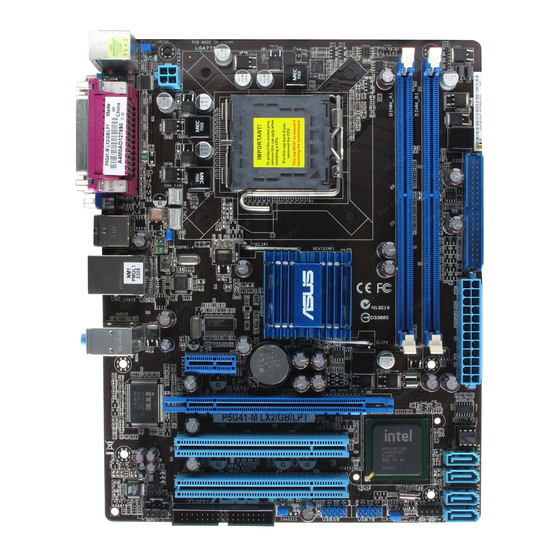
Page 11: Motherboard Overview
Motherboard overview 1.2.1 Motherboard layout Ensure that you install the motherboard into the chassis in the correct orientation. The edge with external ports goes to the rear part of the chassis. 19.1cm(7.5in) KBPWR KBMS ATX12V PRI_IDE LGA775 Place this side towards CHA_FAN the rear of the chassis. CPU_FAN USB34 USBPW1-4 LAN1_USB12 Intel ® 8112L 9LPRS441 AUDIO Lithium Cell PCIEX1 CMOS Power Super PCIEX16 P5G41-M LX2/GB SATA4 SATA3 SATA2…
-
Page 12: Central Processing Unit (Cpu)
Core™2 Quad / Core™2 Extreme / Core™2 Duo / Pentium dual-core / Celeron dual-core / ® ® Celeron processors. ® • Upon purchase of the motherboard, ensure that the PnP cap is on the socket and the socket contacts are not bent. Contact your retailer immediately if the PnP cap is missing, or if you see any damage to the PnP cap/socket contacts/motherboard components. ASUS will shoulder the cost of repair only if the damage is shipment/transit-related. • Keep the cap after installing the motherboard. ASUS will process Return Merchandise Authorization (RMA) requests only if the motherboard comes with the cap on the LGA775 socket. • The product warranty does not cover damage to the socket contacts resulting from incorrect CPU installation/removal, or misplacement/loss/incorrect removal of the PnP cap. The motherboard supports Intel LGA775 processors with the Intel Enhanced Intel ® ® SpeedStep Technology (EIST) and Hyper-Threading Technology.
-
Page 13: Memory Configurations
1.4.2 Memory configurations You may install 512MB, 1GB, 2GB, and 4GB unbuffered non-ECC DDR2 DIMMs into the DIMM sockets. • You may install varying memory sizes in Channel A and Channel B. The system maps the total size of the lower-sized channel for the dual-channel configuration. Any excess memory from the higher-sized channel is then mapped for single-channel operation. • Always install DIMMs with the same CAS latency. For optimum compatibility, it is recommended that you obtain memory modules from the same vendor.
-
Page 14
• Kingston KVR800D2N6/2G(low profile) 2048MB Samsung K4T1G084QE 1.8V • • Kingston KVR800D2N6/4G 4096MB Elpida E2108ABSE-8G-E 1.8V • • Micron MT16HTF25664AY-800G1 2048MB Micron 8ZG27 D9JWB 6-6-6-12 • • OCZ2G800R22GK 1024MB 4-5-5-15 2.0V • • OCZ2P800R22GK 1024MB 4-4-4-15 1.9-2.1V • • (continued on the next page) ASUS P5G41-M LX2 Series… -
Page 15: Memory Configuration
• • V-Data M2GVD6G3H3160Q1E52 512MB V-Data VD29608A8A-25EG20813 • • V-Data M2XSSKG3147C1L1C5Z 1024MB Samsung K4T51083QE • • H5PS1G83EFRS6C V-Data M2XHYKH3J47CC01E5Z 2048MB Hynix • • 852AK SS: Single-sided / DS: Double-sided DIMM support: • A*: Supports one module inserted into either slot as Single-channel memory configuration. • B*: Supports one pair of modules inserted into both slots as one pair of dual-channel memory configuration. Visit the ASUS website at www.asus.com for the latest QVL. Chapter 1: Product introduction…
-
Page 16: Expansion Slots
IRQ assignments. Otherwise, conflicts will arise between the two PCI groups, making the system unstable and the card inoperable. 1.5.3 PCI slots The PCI slot supports cards such as a LAN card, SCSI card, USB card, and other cards that comply with PCI specifications. 1.5.4 PCI Express x1 slot This motherboard supports PCI Express x1 network cards, SCSI cards, and other cards that comply with the PCI Express specifications. 1.5.5 PCI Express x16 slot This motherboard supports a PCI Express x16 graphics card that complies with the PCI Express specifications. ASUS P5G41-M LX2 Series…
-
Page 17: Jumpers
Jumpers Clear RTC RAM (3-pin CLRTC) This jumper allows you to clear the Real Time Clock (RTC) RAM in CMOS. You can clear the CMOS memory of date, time, and system setup parameters by erasing the CMOS RTC RAM data. The onboard button cell battery powers the RAM data in CMOS, which include system setup information such as system passwords. CLRTC P5G41-M LX2/GB Normal Clear RTC (Default) P5G41-M LX2/GB Clear RTC RAM To erase the RTC RAM: 1. Turn OFF the computer and unplug the power cord. 2. Move the jumper cap from pins 1-2 (default) to pins 2-3. Keep the cap on pins 2-3 for about 5-10 seconds, then move the cap back to pins 1-2. 3. Plug the power cord and turn ON the computer. 4. Hold down the <Del> key during the boot process and enter BIOS setup to re-enter data. Except when clearing the RTC RAM, never remove the cap on CLRTC jumper default position. Removing the cap will cause system boot failure! • If the steps above do not help, remove the onboard battery and move the jumper again to clear the CMOS RTC RAM data. After clearing the CMOS, reinstall the battery. • You do not need to clear the RTC when the system hangs due to overclocking. For system failure due to overclocking, use the CPU Parameter Recall (C.P.R.) feature. Shut down and reboot the system, then the BIOS automatically resets parameter settings to default values.
-
Page 18
This jumper allows you to enable or disable the keyboard wake-up feature. When you set this jumper to pins 2–3 (+5VSB), you can wake up the computer by pressing a key on the keyboard (the default is the Space Bar)s. This feature requires an ATX power supply that can supply at least 1A on the +5VSB lead, and a corresponding setting in the BIOS. KBPWR +5VSB (Default) P5G41-M LX2/GB P5G41-M LX2/GB Keyboard Power Setting USB device wake-up (3-pin USBPW1-4, USBPW5-8) Set these jumpers to +5V to wake up the computer from S1 sleep mode (CPU stopped, DRAM refreshed, system running in low power mode) using the connected USB devices. Set to +5VSB to wake up from S3 and S4 sleep modes (no power to CPU, DRAM in slow refresh, power supply in reduced power mode). USBPW1-4 +5VSB (Default) USBPW5-8 P5G41-M LX2/GB +5VSB (Default) P5G41-M LX2/GB USB Device Wake Up ASUS P5G41-M LX2 Series… -
Page 19: Connectors
Connectors 1.7.1 Rear panel ports PS/2 mouse port (green). This port is for a PS/2 mouse. LAN (RJ-45) port. This port allows connection to a Local Area Network (LAN) through a network hub. Refer to the table below for the LAN port LED indications. P5G41-M LX2 LAN port LED indications (Orange) (Green) LED (Orange) LED (Green) Status Description Status Description No link No link ORANGE 100Mbps connection GREEN 10Mbps connection LAN port P5G41-M LX2/GB LAN port LED indications ACT/LINK SPEED Activity/Link LED…
-
Page 20: Internal Connectors
ATX 12V Specification 2.0 or later version and provides a minimum power of 400W. • DO NOT forget to connect the 4-pin ATX12V power plug. Otherwise, the system will not boot. • We recommend that you use a PSU with a higher power output when configuring a system with more power-consuming devices or when you intend to install additional devices. The system may become unstable or may not boot up if the power is inadequate. • If you are uncertain about the minimum power supply requirement for your system, refer to the Recommended Power Supply Wattage Calculator at http://support.asus. com/PowerSupplyCalculator/PSCalculator.aspx?SLanguage=en-us for details. ASUS P5G41-M LX2 Series 1-11…
-
Page 21
CPU and Chassis fan connectors (4-pin CPU_FAN, 3-pin CHA_FAN) Connect the fan cables to the fan connectors on the motherboard, ensuring that the black wire of each cable matches the ground pin of the connector. DO NOT forget to connect the fan cables to the fan connectors. Insufficient air flow inside the system may damage the motherboard components. These are not jumpers! Do not place jumper caps on the fan connectors! Only the 4-pin CPU fan supports the ASUS Q-Fan feature. CHA_FAN Rotation +12V CPU_FAN CPU FAN PWM CPU FAN IN… -
Page 22
IDE ribbon cable to PIN 1. P5G41-M LX2/GB IDE connector Drive jumper setting Mode of device(s) Cable connector Single device Cable-Select or Master Black Master Black Cable-Select Slave Gray Two devices Master Master Black or gray Slave Slave • Pin 20 on the IDE connector is removed to match the covered hole on the Ultra DMA cable connector. This prevents incorrect insertion when you connect the IDE cable. • Use the 80-conductor IDE cable for Ultra DMA 100/66 IDE devices. If any device jumper is set as “Cable-Select,” ensure that all other device jumpers have the same setting. ASUS P5G41-M LX2 Series 1-13… -
Page 23
USB connectors (10-1 pin USB56, USB78) These connectors are for USB 2.0 ports. Connect the USB module cable to any of these connectors, then install the module to a slot opening at the back of the system chassis. These USB connectors comply with USB 2.0 specification that supports up to 480Mbps connection speed. USB56 USB78 PIN 1 PIN 1 P5G41-M LX2/GB P5G41-M LX2/GB USB2.0 connectors Never connect a 1394 cable to the USB connectors. Doing so will damage the motherboard! The USB 2.0 module is purchased separately. 1-14 Chapter 1: Product introduction… -
Page 24
• If you want to connect a high-definition front panel audio module to this connector, set the Front Panel Type item in the BIOS setup to [HD Audio]. If you want to connect an AC’97 front panel audio module to this connector, set the item to [AC97]. By default, this connector is set to [HD Audio]. See section 2.4.2 Chipset for details. Optical drive audio connector (4-pin CD) These connectors allow you to receive stereo audio input from sound sources such as a CD-ROM, TV tuner, or MPEG card. P5G41-M LX2/GB P5G41-M LX2/GB Internal audio connector ASUS P5G41-M LX2 Series 1-15… -
Page 25
System panel connector (10-1 pin F_PANEL) This connector supports several chassis-mounted functions. F_PANEL PLED PWRBTN PIN 1 P5G41-M LX2/GB +HDLED RESET P5G41-M LX2/GB System panel connector • System power LED (2-pin PLED) This 2-pin connector is for the system power LED. Connect the chassis power LED cable to this connector. The system power LED lights up when you turn on the system power, and blinks when the system is in sleep mode. • Hard disk drive activity LED (2-pin +HDLED) This 2-pin connector is for the HDD Activity LED. Connect the HDD Activity LED cable to this connector. The HD LED lights up or flashes when data is read from or written to the HDD. -
Page 26: Software Support
Vista ® ® Service Pack 1 or later versions before installing the drivers for better compatibility and system stability. 1.8.2 Support DVD information The Support DVD that comes with the motherboard package contains the drivers, software applications, and utilities that you can install to avail all motherboard features. The contents of the Support DVD are subject to change at any time without notice. Visit the ASUS website at www.asus.com for updates. To run the Support DVD Place the Support DVD to the optical drive. The DVD automatically displays the Drivers menu if Autorun is enabled in your computer. The following screen is for reference only. Click an icon to display Support DVD/ motherboard information Click an item to install If Autorun is NOT enabled in your computer, browse the contents of the Support DVD to locate the file ASSETUP.EXE from the BIN folder. Double-click the ASSETUP.EXE to run the DVD.
-
Page 27: Chapter 2: Bios Information
Updating the BIOS To update the BIOS: desktop, click Start > Programs > ASUS > ASUSUpdate > From the Windows ® ASUSUpdate to launch the ASUS Update utility. From the dropdown list, select any of the updating process: Updating from the Internet a. Select Update BIOS from the Internet, then click Next. Select the ASUS FTP site nearest you to avoid network traffic, or click Auto Select then click Next. From the FTP site, select the BIOS version that you wish to download then click Next. ASUS P5G41-M LX2 Series…
-
Page 28: Asus Ez Flash 2
ASUS EZ Flash 2 The ASUS EZ Flash 2 feature allows you to update the BIOS without using an OS-based utility. Before you start using this utility, download the latest BIOS file from the ASUS website at www.asus.com. To update the BIOS using EZ Flash 2: Insert the USB flash disk that contains the latest BIOS file to the USB port, then launch EZ Flash 2 in any of these two ways: Press <Alt>…
-
Page 29: Asus Crashfree Bios
2.1.3 ASUS CrashFree BIOS The ASUS CrashFree BIOS is an auto recovery tool that allows you to restore the BIOS file when it fails or gets corrupted during the updating process. You can restore a corrupted BIOS file using the motherboard support DVD or a removable device that contains the updated BIOS file. • The BIOS file in the support DVD may not be the latest version. Download the latest BIOS file from the ASUS website at www.asus.com.
-
Page 30: Main Menu
• The default BIOS settings for this motherboard apply for most conditions to ensure optimum performance. If the system becomes unstable after changing any BIOS settings, load the default settings to ensure system compatibility and stability. Select the Load Setups Default item under the Exit Menu. See section 2.8 Exit Menu. • The BIOS setup screens shown in this section are for reference purposes only, and may not exactly match what you see on your screen. • Visit the ASUS website at www.asus.com to download the latest BIOS file for this motherboard. Main menu When you enter the BIOS Setup program, the Main menu screen appears, giving you an overview of the basic system information. BIOS SETUP UTILITY Main Advanced Power…
-
Page 31: Storage Configuration
Allows you to set the ATA/IDE configuration. Configuration options: [Disabled] [Compatible] [Enhanced] Enhanced Mode Support On [S-ATA] Sets Serial ATA, Parallel ATA or both as native mode. Configuration options: [S-ATA+P-ATA] [S-ATA] [P-ATA]. IDE Detect Time Out (Sec) [35] Selects the time out value for detecting ATA/ATAPI devices. Configuration options: [0] [5] [10] [15] [20] [25] [30] [35] ASUS P5G41-M LX2 Series…
-
Page 32: System Information
2.3.5 System Information This menu gives you an overview of the general system specifications. The BIOS automatically detects the items in this menu. BIOS Information Displays the auto-detected BIOS information. Processor Displays the auto-detected CPU specification. System Memory Displays the auto-detected system memory. Advanced menu The Advanced menu items allow you to change the settings for the CPU and other system devices. Take caution when changing the settings of the Advanced menu items. Incorrect field values can cause the system to malfunction.
-
Page 33: Cpu Configuration
XD feature flag to always return to zero (0). Configuration options: [Disabled] [Enabled] The following item appears only when you installed an Intel Pentium 4 or later CPU that ® ® supports the Enhanced Intel SpeedStep Technology (EIST). ® Intel(R) SpeedStep(TM) Tech [Enabled] Allows you to use the Enhanced Intel SpeedStep Technology. When set to [Enabled], you ® ® can adjust the system power settings in the operating system to use the EIST feature. Set this item to [Disabled] if you do not want to use the EIST. Configuration options: [Enabled] [Disabled] ASUS P5G41-M LX2 Series…
-
Page 34: Chipset
2.4.2 Chipset The Chipset menu allows you to change the advanced chipset settings. Select an item then press <Enter> to display the sub-menu. North Bridge Configuration Memory Remap Feature [Enabled] Allows you to enable or disable the remapping of overlapped PCI memory above the total physical memory. Configuration options: [Enabled] [Disabled] Configure DRAM Timing by SPD [Enabled] Allows you to enable or disable configurating DRAM Timing by SPD. Configuration options: [Enabled] [Disabled] Initiate Graphic Adapter [PEG/PCI] Allows you to select the graphics controller as the primary boot device.
-
Page 35: Onboard Devices Configuration
USB Mass Storage Device Configuration USB Mass Storage Reset Delay [20 Sec] Allows you to set the maximum time that the BIOS waits for the USB storage device to initialize. Configuration options: [10 Sec] [20 Sec] [30 Sec] [40 Sec] Emulation Type [Auto] Allows you to select the emulation type. Configuration options: [Auto] [Floppy] [Forced FDD] [Hard Disk] [CDROM] ASUS P5G41-M LX2 Series…
-
Page 36: Pci Pnp
2.4.5 PCI PnP The PCI PnP menu items allow you to change the advanced settings for PCI/PnP devices. The menu includes setting IRQ and DMA channel resources for either PCI/PnP or legacy ISA devices, and setting the memory size block for legacy ISA devices. Take caution when changing the settings of the PCI PnP menu items. Incorrect field values can cause the system to malfunction. Plug and Play O/S [No] When set to [No], BIOS configures all the devices in the system. When set to [Yes] and if you install a Plug and Play operating system, the operating system configures the Plug and Play devices not required for boot.
-
Page 37: Apm Configuration
(RPM). If the fan is not connected to the motherboard, the field shows N/A. Select Ignored if you do not wish to display the detected speed. VCORE Voltage, 3.3V Voltage, 5V Voltage, 12V Voltage [xxxV] or [Ignored] The onboard hardware monitor automatically detects the voltage output through the onboard voltage regulators. CPU Q-Fan Function [Disabled] Allows you to enable or disable the CPU’s Q-Fan function. Configuration options: [Disabled] [Enabled] ASUS P5G41-M LX2 Series 2-11…
-
Page 38: Boot Menu
2.6.1 Boot Device Priority 1st ~ xxth Boot Device These items specify the boot device priority sequence from the available devices. The number of device items that appears on the screen depends on the number of devices installed in the system. Configuration options: [Removable Dev.] [Hard Drive] [ATAPI CD-ROM] [Disabled] • To select the boot device during system startup, press <F8> when ASUS Logo appears. • To access Windows OS in Safe Mode, do any of the following: ® • Press <F5> when ASUS Logo appears. • Press <F8> after POST. 2.6.2 Boot Settings Configuration…
-
Page 39: Security
[Limited] — allows changes only to selected fields, such as Date and Time. [Full Access] — allows viewing and changing all the fields in the Setup utility. Change User Password Select this item to set or change the user password. The User Password item on top of the screen shows the default Not Installed. After you set a password, this item shows Installed. To set a User Password: Select the Change User Password item and press <Enter>. In the password box, key in a password containing up to six letters or numbers, or both, then press <Enter>. Confirm the password when prompted. The message Password Installed appears after you set your password successfully. To change the user password, follow the same steps in setting a user password. ASUS P5G41-M LX2 Series 2-13…
-
Page 40: Tools Menu
1.FAT 12/16/32 (r/w) 2.NTFS (read only) 3.CD-DISC (read only) 2.7.1 ASUS EZ Flash 2 Allows you to run ASUS EZ Flash 2. When you press <Enter>, a confirmation message appears. Use the left/right arrow key to select between [Yes] or [No], then press <Enter> to confirm your choice. See section 2.1.2 ASUS EZ Flash 2 for details. Exit menu The Exit menu items allow you to load the optimal or failsafe default values for the BIOS items, and save or discard your changes to the BIOS items. BIOS SETUP UTILITY Main Advanced…

Motherboard
P5G41T-M LX2 Series
• P5G41T-M LX2
• P5G41T-M LX2/GB
• P5G41T-M LX2/GB/LPT
-
Драйверы
13
-
Инструкции по эксплуатации
6
Языки:

ASUS P5G41T-M LX2/GB/LPT инструкция по эксплуатации
(58 страниц)
- Языки:Английский
-
Тип:
PDF -
Размер:
2.64 MB -
Описание:
P5G41T-M user’s manual (English)
Просмотр

ASUS P5G41T-M LX2/GB/LPT инструкция по эксплуатации
(60 страниц)
- Языки:Немецкий
-
Тип:
PDF -
Размер:
3.74 MB -
Описание:
P5G41T-M user’s manual (German)
Просмотр

ASUS P5G41T-M LX2/GB/LPT инструкция по эксплуатации
(58 страниц)
- Языки:Японский
-
Тип:
PDF -
Размер:
2.84 MB -
Описание:
P5G41T-M user’s manual (Japanese)
Просмотр

ASUS P5G41T-M LX2/GB/LPT инструкция по эксплуатации
(59 страниц)
- Языки:Французский
-
Тип:
PDF -
Размер:
2.61 MB -
Описание:
P5G41T-M user’s manual (French)
Просмотр

ASUS P5G41T-M LX2/GB/LPT инструкция по эксплуатации
(58 страниц)
- Языки:Китайский
-
Тип:
PDF -
Размер:
2.96 MB -
Описание:
P5G41T-M user’s manual (Traditional Chinese)
Просмотр

ASUS P5G41T-M LX2/GB/LPT инструкция по эксплуатации
(27 страниц)
-
Тип:
PDF -
Размер:
3.39 MB -
Описание:
P5G41T-M Asian Quick Start Guide for Multiple Languages
Просмотр
На NoDevice можно скачать инструкцию по эксплуатации для ASUS P5G41T-M LX2/GB/LPT. Руководство пользователя необходимо для ознакомления с правилами установки и эксплуатации ASUS P5G41T-M LX2/GB/LPT. Инструкции по использованию помогут правильно настроить ASUS P5G41T-M LX2/GB/LPT, исправить ошибки и выявить неполадки.
Инструкция и руководство для
Asus P5G41-M LX на русском на испанском на французском на итальянском на чешском на немецком на польском


41 страница подробных инструкций и пользовательских руководств по эксплуатации
 12:31
12:31
Сборка бюджетного игрового компьютера
 06:52
06:52
Asus p5g41t-m lx2/gb + xeon e5450 — быстрый курс по установке ксеона 
 13:35
13:35
ASUS P5G41-M LX XEON X5472 1600FSB+BECHMARK TEST+GTA V GAME TEST
 03:49
03:49
ОБЗОР МАТЕРИНСКОЙ ПЛАТЫ Asus p5g41t m lx2 v2
 08:22
08:22
Материнская плата c AliExpress LGA 775 ddr3 ( Asus p5p41t le )
 12:44
12:44
Разгон Xeon E5450 на Asus P5G41T-MLX
 17:56
17:56
XEON E5462 CPU 1600FSB-ASUS P5G41-M LX GAME TEST-BENCHMARK TEST
 02:53
02:53
Разгон Xeon e5450(x5450) на g41 чипсете
Français Deutsh Italiano Español Русский Português Polski Če…
P5g41-m lx, Motherboard, Quick start guide
- Изображение
- Текст
Français
Deutsh
Italiano
Español
Русский
Português
Polski
Česky
Magyar
Български
Română
Srpski
Türkçe
Quick Start Guide
First Edition
February 2009
Copyright © 2009 ASUSTeK COMPUTER INC.
All Rights Reserved
U4972
P5G41-M LX
Motherboard

Installer le cpu, Layout de la carte mère, Français
Asus p5g41-m lx, F_panel, P5g41-m lx, Usbpw5-8, Usbpw1-4, Kbpwr
- Изображение
- Текст
2
Français
ASUS P5G41-M LX
2.
Installer le CPU
Pour installer le CPU :
1. Pressez le levier avec votre pouce (A) et déplacez-le vers la gauche (B)
jusqu’à ce qu’il soit libéré de son onglet de rétention.
1.
Layout de la carte mère
A
B
Languette de
retenue
Levier
Ce côté doit être face à vous.
Capuchon PnP
P5G41-M LX
PCIEX16
PCIEX1_1
PCIEX1_2
PCI1
PRI_IDE
USB56
USB78
F_PANEL
AAFP
IC
S
9LRS954
ATX12V
EATXPW
R
CPU_FAN
Intel
®
G41
Lithium Cell
CMOS Power
Super
I/O
AUDIO
ALC
662-VC1
RTL
8103EL
KBMS
8Mb
BIOS
SB_PWR
CLRTC
USBPW1-4
USBPW5-8
KBPWR
SPEAKER
18.3cm(7.2in)
24.4cm(9.6in)
LGA775
Intel
®
ICH7
DDR2 DIMM_A1 (64bit, 240-pin module)
DDR2 DIMM_B1 (64bit, 240-pin module)
VG
A
COM1
LAN1_USB12
USB34
SATA1 SATA3
SATA2
SATA4
CHA_FAN
1 2
2 3
Normal
(Default)
Clear RTC
CLRTC
2
1
2 3
+5V
(Default)
+5VSB
USBPW5-8
2
1
2
3
+5V
+5VSB
(Default)
USBPW1-4
2
1
2 3
+5V
(Default)
+5VSB
KBPWR
PIN 1
PWR BTN
PLED
+
PLED
—
PWR
GND
HD_LED
+
HD_LED-
Groun
d
Rese
t
F_PANEL
PLED
+HDLED
RESET

Français
ASUS P5G41-M LX
2. Soulevez le levier dans un angle de 135º.
3. Soulevez la plaque avec votre pouce et votre index à un angle de 100º, puis
enlevez le couvercle PnP de la plaque.
4. Placez le CPU sur le socket, en vous assurant que la marque en forme de
triangle doré est placée en bas à gauche du socket. Les ergots d’alignement
du socket doivent correspondre aux encoches du CPU.
5. Refermez la plaque, puis pressez le levier jusqu’à ce qu’il se loge dans le
loquet de rétention.
• Pour éviter d’endommager les broches du socket, ne retirez le couvercle
PnP que lors de l’installation d’un CPU.
• Veuillez garder le couvercle en cas de retour du produit.
• La garantie de ce produit ne couvre pas les dommages causés aux broches
du socket.
.
Mémoire Système
Vous pouvez installer des DIMM DDR2 GB unbuffered non-ECC de 512 MO, 1 Go,
2 Go et 4 Go dans les sockets.
• Vous pouvez installer des modules mémoire de tailles variables dans le
Canal A et B. Le système mappe la taille totale du canal de plus petite taille
pour les configurations dual-channel. Tout excédant de mémoire du canal
le plus grand est alors mappé pour fonctionner en single-channel.
• Installez toujours des modules mémoire avec une latence CAS identique.
Pour obtenir une compatibilité optimale, il vous est recommandé de vous
équiper des modules de mémoire auprès du même vendeur.
• En raison des limitations d’adressage mémoire sur les systèmes
d’exploitation Windows 32-bits, lorsque vous installez 4Go ou plus de
mémoire sur cette carte mère, le montant de mémoire utilisable par le
système d’exploitation sera de 3 Go ou moins. Pour une utilisation effective
de la mémoire, vous pouvez :
—
Utiliser un maximum de 3 Go lors de l’utilisation d’un système
d’exploitation 32-bits.
—
Installer un système d’exploitation Windows 64-bits si vous
souhaitez installer 4 Go ou plus de mémoire sur cette carte
mère.
• Cette carte mère ne supporte pas les modules mémoire composés de
puces mémoire de 256 Mo ou moins.
Canal
Emplacements
Canal A
DIMM_A1
Canal B
DIMM_B1

Informations du bios, Informations sur le dvd de support, Français
Страница 4
- Изображение
- Текст
4
Français
ASUS P5G41-M LX
4.
Informations du BIOS
Utilisez le programme de configuration du BIOS pour mettre à jour le BIOS ou
configurer ses paramètres. Les écrans BIOS comprennent les clés de navigation
et une courte aide en ligne pour vous guider. Si vous rencontrez des problèmes
liés au système ou si le système devient instable une fois que vous aurez modifié
les paramètres, chargez les Paramètres de Réglage Par Défaut. Rendez visite au
site web d’ASUS (www.asus.com) pour obtenir les mises à jour.
Pour accéder au Setup lors du démarrage:
Pressez <Suppr> lors du Test Automatique de Démarrage (POST : Power-On
Self Test ). Si vous ne pressez pas la touche <Suppr>, le POST continuera son
programme de test.
Pour accéder au programme de configuration du BIOS après le POST :
• Redémarrez le système en pressant <Ctrl> + <Alt> + <Suppr>, puis pressez
<Suppr> lors du POST, ou
• Pressez le bouton de réinitialisation situé sur le châssis puis pressez <Suppr>
lors du POST, ou
• Eteignez et rallumez le système puis pressez <Suppr> lors du POST.
Pour mettre à jour le BIOS avec ASUS EZ Flash 2 :
Démarrez le système et appuyez sur <Alt> + <F2> lors du POST pour lancer EZ
Flash 2. Insérez un disque flash USB contenant le dernier fichier image du BIOS.
EZ Flash 2 lance le processus de mise à jour du BIOS et redémarre le système
automatiquement une fois terminé.
Pour restaurer le BIOS avec CrashFree BIOS :
Démarrez le système. Si le BIOS est corrompu, l’outil de restauration automatique CrashFree
BIOS 3 vérifiera la présence du fichier du BIOS sur le lecteur optique et le disque flash
USB. Connectez un disque flash USB ou insérez le DVD de support dans le lecteur optique
contenant le dernier fichier image du BIOS ou celui d’origine. Redémarrez le système une
fois le processus de restauration du BIOS terminé.
5.
Informations sur le DVD de support
Cette carte mère supporte les systèmes d’exploitation Windows
®
XP / Vista. Installez
toujours la dernière version d’OS et les mises à jour correspondantes de manière à profiter
pleinement des caractéristiques de votre matériel.
Le DVD de support livré avec la carte mère contient les pilotes, les applications logicielles,
et les utilitaires que vous pouvez installer pour tirer partie de toutes les fonctions de la carte
mère.
Si l’Exécution automatique n’est pas activée sur votre ordinateur, parcourez
le contenu du DVD de support pour localiser le fichier ASSETUP.EXE dans le
répertoire BIN. Double-cliquez sur ASSETUP.EXE pour lancer le DVD.

Motherboard-layout 2. installieren der cpu, Deutsch, F_panel
Asus p5g41-m lx, P5g41-m lx, Usbpw5-8, Usbpw1-4, Kbpwr
- Изображение
- Текст
5
ASUS P5G41-M LX
Deutsch
A
B
1.
Motherboard-Layout
2.
Installieren der CPU
So installieren Sie den Prozessor:
1. Drücken Sie den Arretierhebel mit Ihrem Daumen (A) und schieben Sie ihn nach
links (B), bis er vom Halteriegel losgelassen wird.
Ladehebel
Halteriegel
PnP-Kappe
Diese Seite der Cam-Box
sollte zu Ihnen zeigen.
P5G41-M LX
PCIEX16
PCIEX1_1
PCIEX1_2
PCI1
PRI_IDE
USB56
USB78
F_PANEL
AAFP
IC
S
9LRS954
ATX12V
EATXPW
R
CPU_FAN
Intel
®
G41
Lithium Cell
CMOS Power
Super
I/O
AUDIO
ALC
662-VC1
RTL
8103EL
KBMS
8Mb
BIOS
SB_PWR
CLRTC
USBPW1-4
USBPW5-8
KBPWR
SPEAKER
18.3cm(7.2in)
24.4cm(9.6in)
LGA775
Intel
®
ICH7
DDR2 DIMM_A1 (64bit, 240-pin module)
DDR2 DIMM_B1 (64bit, 240-pin module)
VG
A
COM1
LAN1_USB12
USB34
SATA1 SATA3
SATA2
SATA4
CHA_FAN
1 2
2 3
Normal
(Default)
Clear RTC
CLRTC
2
1
2 3
+5V
(Default)
+5VSB
USBPW5-8
2
1
2
3
+5V
+5VSB
(Default)
USBPW1-4
2
1
2 3
+5V
(Default)
+5VSB
KBPWR
PIN 1
PWR BTN
PLED
+
PLED
—
PWR
GND
HD_LED
+
HD_LED-
Groun
d
Rese
t
F_PANEL
PLED
+HDLED
RESET

ASUS P5G41-M LX
Deutsch
.
Arbeitsspeicher
Sie können 512 MB, 1 GB, 2 GB und 4 GB ungepufferte nicht-ECC DDR2 DIMMs in
den DIMM-Sockeln installieren.
2. Heben Sie den Arretierhebel bis zu einem Winkel von 135º hoch.
3. Heben Sie die Deckplatte mit Daumen und Zeigefinger bis zu einem Winkel von
100º hoch, und drücken Sie die PnP-Abdeckung von der Deckplattenaussparung,
um sie zu entfernen.
4. Legen Sie die CPU auf den Sockel. Richten Sie dabei das goldene Dreieck auf
die linke untere Kante des Sockels aus. Die Sockelausrichtungsnase muss in
die CPU-Kerbe einpassen.
5. Schließen Sie die Deckplatte und drücken Sie dann den Arretierhebel, bis er in
den Halteriegel einrastet.
•
Um Schäden an den Sockelpolen zu vermeiden, entfernen Sie bitte die PnP-Abdeckung nicht
vor dem Beginn der CPU-Installation.
•
Bitte bewahren Sie die Abdeckung fär den Fall einer Räckgabe des Produktes auf.
•
Die Produktgarantie deckt keine Beschädigung der Sockelpole ab.
Kanal
Steckplätze
Kanal A
DIMM_A1
Kanal B
DIMM_B1
• Sie können verschiedene Speichergrößen in Channel A und Channel B
installieren. Das System ordnet die gesamte Größe des weniger belegten
Kanals für die Dual-Channel-Konfiguration zu. Der überschüssige Speicher
des höher belegten Kanals wird dann der Single-Channel-Konfiguration
zugeordnet.
• Installieren Sie immer DIMMs mit gleicher CAS-Latenzzeit. Für optimale
Installieren Sie immer DIMMs mit gleicher CAS-Latenzzeit. Für optimale
Kompatibilität wird empfohlen, nur Speichermodule eines Herstellers zu
verwenden.
• Durch die Speicheradressenbeschränkung in 32-Bit-Windows
®
können vom
Betriebssystem nur 3GB oder weniger benutzt werden, selbst wenn 4GB
installiert wurden. Für eine effektive Speichernutzung empfehlen wir Ihnen
folgendes:
— Installieren Sie maximal 3GB Speicher, wenn Sie ein 32-Bit-Windows
Installieren Sie maximal 3GB Speicher, wenn Sie ein 32-Bit-Windows
®
—
betriebssystem benutzen.
— Installieren Sie ein 64-Bit-Windows
®
-betriebssystem, wenn Sie auf dem
Motherboard 4GB oder mehr Speicher installieren wollen.
• Dieses Motherboard unterstützt keine DIMMs, die aus 256 Megabit- (Mb)
Chips oder weniger hergestellt wurden.

7
ASUS P5G41-M LX
Deutsch
4.
BIOS-Informationen
Benutzen Sie das BIOS-Einstellungsprogramm zum aktualisieren des BIOS oder
zur Konfiguration seiner Parameter. Die BIOS-Anzeigen enthalten Navigations-
anleitungen und eine kurze Online-Hilfe, um Ihnen die Verwendung zu erleichtern.
Falls in Ihrem System Probleme auftauchen, oder das System nach dem Verändern
einiger Einstellungen instabil wird, sollten Sie die Standardeinstellungen zurückholen.
Weitere Neuigkeiten finden Sie auf der ASUS-Webseite (www.asus.com).
So öffnen Sie das BIOS-Setup beim Systemstart:
Drücken Sie <Entf> während des Power-On Self-Test (POST). Wenn Sie nicht <Entf>
drücken, fährt der POST mit seiner Routine fort.
So öffnen Sie das Setup nach dem POST:
• Starten Sie das System neu, indem Sie <Strg> + <Alt> + <Entf> drücken, und
drücken Sie dann <Entf> während des POST, oder
• Drücken Sie den Reset-Schalter am Computergehäuse, und drücken Sie dann
<Entf> während des POST, oder
• Schalten Sie das System aus und wieder an, und drücken Sie dann <Entf>
während des POST
Aktualisieren des BIOS mit ASUS EZ Flash 2:
Booten Sie das System neu und drücken <Alt> + <F2> während des POST, um
EZ Flash 2 zu starten. Legen Sie die Diskette, die die neueste BIOS-Datei enthält,
ein. EZ Flash 2 führt den BIOS-Aktualisierungsprozess aus und startet das System
automatisch nach dem Vervollständigen des Prozesses neu.
So stellen Sie das BIOS mit CrashFree BIOS wieder her:
Starten Sie das System. Falls die BIOS-Datei beschädigt ist, sucht das CrashFree
BIOS 3-Wiederherstellungsprogramm nach einer Diskette oder DVD, mit der das BIOS
wieder hergestellt werden kann. Legen Sie die Support-DVD des Motherboards, oder
eine Diskette mit der ursprünglichen oder einer neueren BIOS-Datei ein. Starten Sie
das System neu, wenn das BIOS wieder hergestellt ist.
5.
Software-Unterstützungbg
Das Motherboard unterstützt Windows
®
XP/Vista Betriebssysteme (OS). Installieren
Sie bitte immer die neueste OS-Version und die entsprechenden Updates, um die
Funktionen Ihrer Hardware zu maximieren.
Die mit dem Motherboard gelieferte Support-DVD enthält die Treiber, Anwendungs-
Software und Programme die Sie installieren können, um alle Motherboard-
Funktionen benutzen zu können. Es wird bei aktivierter Autorun-Funktion
automatisch das Treibermenü angezeigt.
Wenn Autorun nicht aktiviert ist, durchsuchen Sie den Inhalt der Support-DVD,
um die Datei ASSETUP.EXE im Ordner BIN zu finden. Doppelklicken Sie auf
das Dateisymbol ASSETUP.EXE, um die DVD auszuführen.

Italiano, F_panel, Asus p5g41-m lx
P5g41-m lx, Usbpw5-8, Usbpw1-4, Kbpwr
- Изображение
- Текст
ASUS P5G41-M LX
Italiano
A
B
1.
Diagramma disposizione scheda madre
2.
Installazione della CPU
Installazione della CPU:
1. Premere la levetta di carico con il pollice (A), poi spostarla e sinistra (B) finché
è liberata dalla linguetta di trattenimento.
Levetta di carico
Linguetta di trattenimento
Copertura PnP
Questo lato del modulo deve essere
rivolto verso sé stessi.
P5G41-M LX
PCIEX16
PCIEX1_1
PCIEX1_2
PCI1
PRI_IDE
USB56
USB78
F_PANEL
AAFP
IC
S
9LRS954
ATX12V
EATXPW
R
CPU_FAN
Intel
®
G41
Lithium Cell
CMOS Power
Super
I/O
AUDIO
ALC
662-VC1
RTL
8103EL
KBMS
8Mb
BIOS
SB_PWR
CLRTC
USBPW1-4
USBPW5-8
KBPWR
SPEAKER
18.3cm(7.2in)
24.4cm(9.6in)
LGA775
Intel
®
ICH7
DDR2 DIMM_A1 (64bit, 240-pin module)
DDR2 DIMM_B1 (64bit, 240-pin module)
VG
A
COM1
LAN1_USB12
USB34
SATA1 SATA3
SATA2
SATA4
CHA_FAN
1 2
2 3
Normal
(Default)
Clear RTC
CLRTC
2
1
2 3
+5V
(Default)
+5VSB
USBPW5-8
2
1
2
3
+5V
+5VSB
(Default)
USBPW1-4
2
1
2 3
+5V
(Default)
+5VSB
KBPWR
PIN 1
PWR BTN
PLED
+
PLED
—
PWR
GND
HD_LED
+
HD_LED-
Groun
d
Rese
t
F_PANEL
PLED
+HDLED
RESET

9
ASUS P5G41-M LX
Italiano
3.
Memoria di sistema
Nelle prese per DIMM, si possono installare moduli di memoria DIMM DDR non-ECC,
senza buffer, da 512 MB, 1 GB, 2 GB e da 4 GB.
2. Sollevare la levetta di carico nella direzione indicata dalla freccia ad un anglo
di 135°.
3. Sollevare la placca di carico con il pollice e l’indice ad un angolo di 100º (A),
poi spingere la copertura PnP dalla placca di carico per rimuoverla (B).
4. Collocare la CPU sopra la presa, assicurandosi che il triangolo dorato si trovi
nell’angolo in basso a sinistra della presa. Il tasto di allineamento della presa
deve adattarsi alla dentellatura della CPU.
5. Chiudere la placca di carico (A), poi spingere la leva di carico (B) finché scatta
nella linguetta di trattenimento.
•
Per evitare di danneggiare i pin, non rimuovere la copertura PnP salvo
si stia installando una CPU.
•
Conservare il cappuccio per eventuali restituzioni del prodotto.
•
La garanzia del prodotto non copre i danni ai pin della presa.
Canale doppio
Prese
Coppia A
DIMM_A1
Coppia B
DIMM_B1
• È possibile installare diversi formati di memoria nei canali A e B. Il sistema
mappa la dimensione totale del canale di dimensione più piccolo per la
configurazione a canale doppio. Qualsiasi accesso alla memoria dal canale
di dimensione maggiore, viene quindi mappato per il funzionamento a canale
singolo.
• Utilizzare e installare sempre moduli DIMM con la stessa latenza CAS. Per
poter garantire la perfetta compatibilità dei moduli, si raccomanda di utilizzare
moduli di memoria acquistati presso lo stesso venditore.
• A causa dei limiti con gli indirizzi di memoria nel sistema operativo Windows®
a 32 bit, quando si installa una memoria da 4GB o più sulla scheda madre, la
memoria effettivamente utilizzabile dal sistema operativa può essere di 3GB
o meno. Per usare in modo efficace la memoria, si raccomanda di eseguire
una delle seguenti azioni:
— Usare 3GB di memoria di sistema al massimo se si utilizza il sistema
Usare 3GB di memoria di sistema al massimo se si utilizza il sistema
operativo Windows® a 32 bit.
— Per installare 4GB di memoria o più sulla scheda madre, installare il
sistema operativo Windows® a 64 bit.
• Questa scheda madre non supporta DIMM da 256 megabit (Mb) o minori.

Informazioni sul bios, Italiano, Supporto per il software
Страница 10
- Изображение
- Текст
10
ASUS P5G41-M LX
Italiano
4.
Informazioni sul BIOS
Usare l’utilità per la configurazione del BIOS per aggiornare il BIOS o configurarne i
parametri. La schermata BIOS include tasti di navigazione ed una concisa guida in
linea. Se si riscontrano problemi con il sistema, oppure se questo diventa instabile
dopo avere modificato le impostazioni, caricare le impostazioni predefinite di
configurazione Setup Defaults. Visitare la pagina Web ASUS (www.asus.com) per
gli aggiornamenti.
Per accedere al Setup all’avvio:
Premere il tasto <Delete> durante il POST (Power On Self Test). Se non si preme il
tasto <Delete>, il POST continua le sue routine di diagnostica.
Per accedere al Setup dopo il POST:
• Riavviare il sistema premendo i tasti <Ctrl> + <Alt> + <Delete>, poi premere il
tasto <Delete> durante il POST, oppure
• Premere il tasto di ripristino sul telaio, poi premere il tasto <Delete> durante il
POST, oppure
• Spegnere e riaccendere il sistema e poi premere il tasto <Delete> durante il
POST
Aggiornare il BIOS con ASUS EZ Flash 2:
Avviare il sistema e premere <Alt> + <F2> nel corso del POST per lanciare EZ Flash 2.
Inserire una memoria flash USB contenente il file con la versione più recente del BIOS.
EZ Flash 2 esegue il processo di aggiornamento del BIOS e riavvia automaticamente
il sistema una volta completato.
Ripristinare il BIOS con CrashFree BIOS :
Avviare il sistema. Se il BIOS è danneggiato, lo strumento per il ripristino automatico
CrashFree BIOS 3 verifica l’unità ottica e la memoria flash USB per verificare la
presenza di un file BIOS in modo da poter procedere al ripristino del BIOS: Inserire
una memoria flash USB o il DVD di supporto che contiene il file con la versione più
recente o originale del BIOS. Riavviare il sistema dopo avere eseguito il ripristino
del BIOS.
5.
Supporto per il software
Questa scheda madre supporta un sistema operativo (OS) Windows
®
XP/Vista.
Installate sempre l’ultima versione OS e gli aggiornamenti corrispondenti, in modo
da massimizzare le funzioni del vostro hardware.
Il DVD di supporto fornito con il pacchetto della scheda madre contiene i driver, le
applicazioni software e le utilità che possono essere installate per poter sfruttare tutte
le caratteristiche della scheda madre. Viene visualizzato automaticamente il menu
Driver se sul computer è attiva l’Esecuzione automatica.
Se sul computer non è attiva ESECUZIONE AUTOMATICA, sfogliare i contenuti
del DVD di supporto per individuare il file ASSETUP.EXE nella cartella BIN.
Fare doppio clic su ASSETUP.EXE per eseguire il DVD.
