Руководства пользователя
Версия T4204
1.97 MB
Motherboard Installation Guide (Traditional Chinese)
Версия C4204
1.83 MB
Motherboard Installation Guide (Simplified Chinese)
Версия QJ4204
1.68 MB
Motherboard Installation Guide (Japanese)
Версия QG4204
1.6 MB
Motherboard Installation Guide (German)
Версия QF4204
1.59 MB
Motherboard Installation Guide (French)
Версия Q4204
43.39 MB
Motherboard Installation Guide (Multiple Languages)
Версия C3873
3.72 MB
P5K/EPU user’s manual(Simplified Chinese)
Версия T3873
3.83 MB
P5K/EPU user’s manual(Traditional Chinese)
Версия E3873
4 MB
P5K/EPU user’s manual(English)
Версия C3672
3.72 MB
P5K/EPU user’s manual(Simplified Chinese)
Версия T3672
3.84 MB
P5K/EPU user’s manual(Traditional Chinese)
Версия F3691b
3.64 MB
P5K/EPU user’s manual(French)
Версия G3691b
3.63 MB
P5K/EPU user’s manual(German)
Версия IE3872
109.92 KB
P5K/EPU user’s insertpage (English)
Версия F3691
3.65 MB
P5K/EPU user’s manual(French)
Версия IE3824
110.52 KB
P5K/EPU user’s insertpage (English)
Версия E3691
4.02 MB
P5K/EPU user’s manual(English)
Версия T2437
2.57 MB
Motherboard DIY Troubleshooting Guide (Traditional Chinese version)
-
Драйверы
19
-
Инструкции по эксплуатации
13
Языки:

ASUS P5K/EPU инструкция по эксплуатации
(148 страниц)
- Языки:Английский
-
Тип:
PDF -
Размер:
5.14 MB -
Описание:
P5K/EPU user’s manual(English)
Просмотр

ASUS P5K/EPU инструкция по эксплуатации
(40 страниц)
- Языки:Молдавский, Немецкий
-
Тип:
PDF -
Размер:
1.65 MB -
Описание:
Motherboard Installation Guide (German)
Motherboard Installation Guide (German)
Просмотр

ASUS P5K/EPU инструкция по эксплуатации
(150 страниц)
- Языки:Французский
-
Тип:
PDF -
Размер:
4 MB -
Описание:
P5K/EPU user’s manual(French)
Просмотр

ASUS P5K/EPU инструкция по эксплуатации
(148 страниц)
- Языки:Французский
-
Тип:
PDF -
Размер:
3.99 MB -
Описание:
P5K/EPU user’s manual(French)
Просмотр

ASUS P5K/EPU инструкция по эксплуатации
(156 страниц)
- Языки:Китайский
-
Тип:
PDF -
Размер:
4.2 MB -
Описание:
P5K/EPU user’s manual(Traditional Chinese)
Просмотр

ASUS P5K/EPU инструкция по эксплуатации
(156 страниц)
- Языки:Китайский
-
Тип:
PDF -
Размер:
4.08 MB -
Описание:
P5K/EPU user’s manual(Simplified Chinese)
Просмотр

ASUS P5K/EPU инструкция по эксплуатации
(156 страниц)
- Языки:Китайский
-
Тип:
PDF -
Размер:
4.2 MB -
Описание:
P5K/EPU user’s manual(Traditional Chinese)
Просмотр

ASUS P5K/EPU инструкция по эксплуатации
(44 страницы)
- Языки:Китайский, Молдавский
-
Тип:
PDF -
Размер:
1.88 MB -
Описание:
Motherboard Installation Guide (Simplified Chinese)
Просмотр

ASUS P5K/EPU инструкция по эксплуатации
(44 страницы)
- Языки:Китайский, Молдавский
-
Тип:
PDF -
Размер:
2.02 MB -
Описание:
Motherboard Installation Guide (Traditional Chinese)
Просмотр

ASUS P5K/EPU инструкция по эксплуатации
(8 страниц)
- Языки:Китайский, Молдавский
-
Тип:
PDF -
Размер:
2.67 MB -
Описание:
Motherboard DIY Troubleshooting Guide (Traditional Chinese version)
Просмотр

ASUS P5K/EPU инструкция по эксплуатации
(40 страниц)
- Языки:Молдавский, Японский
-
Тип:
PDF -
Размер:
1.73 MB -
Описание:
Motherboard Installation Guide (Japanese)
Просмотр

ASUS P5K/EPU инструкция по эксплуатации
(40 страниц)
- Языки:Молдавский, Французский
-
Тип:
PDF -
Размер:
1.64 MB -
Описание:
Motherboard Installation Guide (French)
Просмотр

ASUS P5K/EPU инструкция по эксплуатации
(721 страница)
- Языки:Молдавский
-
Тип:
PDF -
Размер:
43.88 MB -
Описание:
Motherboard Installation Guide (Multiple Languages)
Просмотр
На NoDevice можно скачать инструкцию по эксплуатации для ASUS P5K/EPU. Руководство пользователя необходимо для ознакомления с правилами установки и эксплуатации ASUS P5K/EPU. Инструкции по использованию помогут правильно настроить ASUS P5K/EPU, исправить ошибки и выявить неполадки.
Инструкция и руководство для
Asus P5KPL/EPU  на русском на испанском на французском на итальянском на чешском на немецком на польском


38 страниц подробных инструкций и пользовательских руководств по эксплуатации
 06:14
06:14
Материнская плата ASUS P5QPL-AM. Что и где на ней находится.
 06:24
06:24
Как прошить материнку под XEON? Asus P5kpl-am Обзор и Разгон процессора!
 07:14
07:14
Абргейд компьютера на основе материнской платы ASUS P5KPL
 05:25
05:25
Материнская Плата Asus P5KPL-AM SE под Xeon e5440 с Алиэкспресс + Биос для Ксеонов
 04:18
04:18
ASUS P5KPL-AM bios XEON
 01:50
01:50
Материнская плата P5KPL AM EPU краткий обзор
 15:17
15:17
Motherboard replacement. P5KPL-AM EPU Unboxing and installing
 01:08
01:08
Overclock Asus P5KPL-AM EPu (2.5ghz to 2.9ghz) Intel Celeron e3300
Français Deutsh Italiano Español Русский Português Polski Če…
P5kpl/epu, Motherboard, Quick start guide
- Изображение
- Текст
Français
Deutsh
Italiano
Español
Русский
Português
Polski
Česky
Magyar
Български
Română
Srpski
Quick Start Guide
First Edition
April 2009
Copyright © 2009 ASUSTeK COMPUTER INC.
All Rights Reserved
U4402
P5KPL/EPU
Motherboard

2
Français
ASUS P5KPL/EPU
A
B
2.
Installer le CPU
Pour installer le CPU :
1. Pressez le levier avec votre pouce (A) et déplacez-le vers la gauche (B)
jusqu’à ce qu’il soit libéré de son onglet de rétention.
1.
Layout de la carte mère
Languette de
retenue
Levier
Ce côté doit être face à vous.
Capuchon PnP

Français
ASUS P5KPL/EPU
2. Soulevez le levier dans un angle de 135º.
3. Soulevez la plaque avec votre pouce et votre index à un angle de 100º, puis
enlevez le couvercle PnP de la plaque.
4. Placez le CPU sur le socket, en vous assurant que la marque en forme de
triangle doré est placée en bas à gauche du socket. Les ergots d’alignement
du socket doivent correspondre aux encoches du CPU.
5. Refermez la plaque, puis pressez le levier jusqu’à ce qu’il se loge dans le
loquet de rétention.
• Pour éviter d’endommager les broches du socket, ne retirez le couvercle
PnP que lors de l’installation d’un CPU.
• Veuillez garder le couvercle en cas de retour du produit.
• La garantie de ce produit ne couvre pas les dommages causés aux broches
du socket.
.
Mémoire Système
Vous pouvez installer des DIMM DDR2 GB unbuffered non-ECC de 512 MO, 1 Go
et 2 Go dans les sockets.
• Pour une con��guration double canal, la taille totale des modules de
Pour une con��guration double canal, la taille totale des modules de
mémoire installés par canal doit être identique (DIMM_A1 = DIMM_B1).
• Installez toujours des modules mémoire avec une latence CAS identique.
Pour obtenir une compatibilité optimale, il vous est recommandé de vous
équiper des modules de mémoire auprès du même vendeur.
• En raison des limitations d’adressage mémoire sur les systèmes
d’exploitation Windows 32-bits, lorsque vous installez 4Go ou plus de
mémoire sur cette carte mère, le montant de mémoire utilisable par le
système d’exploitation sera de 3 Go ou moins. Pour une utilisation effective
de la mémoire, vous pouvez :
—
Utiliser un maximum de 3 Go lors de l’utilisation d’un système
d’exploitation 32-bits.
—
Installer un système d’exploitation Windows 64-bits si vous souhaitez
installer 4 Go ou plus de mémoire sur cette carte mère.
• Cette carte mère ne supporte pas les modules mémoire composés de
puces mémoire de 256 Mo ou moins.
• Seul le slot jaune peut supporter un overclocking mémoire de 1066MHz.
• Lors de l’utilisation de quatre modules mémoire DDR2, installez seulement des modules
à une seule face.
Canal
Emplacements
Canal A
DIMM_A1 et DIMM_A2
Canal B
DIMM_B1 et DIMM_B2

Informations du bios, Informations sur le dvd de support, Français
Страница 4
- Изображение
- Текст
4
Français
ASUS P5KPL/EPU
4.
Informations du BIOS
Utilisez le programme de con��guration du BIOS pour mettre à jour le BIOS ou
con��gurer ses paramètres. Les écrans BIOS comprennent les clés de navigation
et une courte aide en ligne pour vous guider. Si vous rencontrez des problèmes
liés au système ou si le système devient instable une fois que vous aurez modi��é
les paramètres, chargez les Paramètres de Réglage Par Défaut. Rendez visite au
site web d’ASUS (www.asus.com) pour obtenir les mises à jour.
Pour accéder au Setup lors du démarrage:
Pressez <Suppr> lors du Test Automatique de Démarrage (POST : Power-On
Self Test ). Si vous ne pressez pas la touche <Suppr>, le POST continuera son
programme de test.
Pour accéder au programme de configuration du BIOS après le POST :
• Redémarrez le système en pressant <Ctrl> + <Alt> + <Suppr>, puis pressez
<Suppr> lors du POST, ou
• Pressez le bouton de réinitialisation situé sur le châssis puis pressez <Suppr>
lors du POST, ou
• Eteignez et rallumez le système puis pressez <Suppr> lors du POST.
Pour mettre à jour le BIOS avec ASUS EZ Flash 2 :
Démarrez le système et appuyez sur <Alt> + <F2> lors du POST pour lancer EZ
Flash 2. Insérez un disque flash USB contenant le dernier ��chier image du BIOS.
EZ Flash 2 lance le processus de mise à jour du BIOS et redémarre le système
automatiquement une fois terminé.
Pour restaurer le BIOS avec CrashFree BIOS :
Démarrez le système. Si le BIOS est corrompu, l’outil de restauration automatique CrashFree
BIOS 3 véri��era la présence du ��chier du BIOS sur le lecteur optique et le disque flash
USB. Connectez un disque flash USB ou insérez le CD de support dans le lecteur optique
contenant le dernier ��chier image du BIOS ou celui d’origine. Redémarrez le système une
fois le processus de restauration du BIOS terminé.
5.
Informations sur le DVD de support
Cette carte mère supporte les systèmes d’exploitation Windows
®
XP / Vista. Installez
toujours la dernière version d’OS et les mises à jour correspondantes de manière à pro��ter
pleinement des caractéristiques de votre matériel.
Le DVD de support livré avec la carte mère contient les pilotes, les applications logicielles,
et les utilitaires que vous pouvez installer pour tirer partie de toutes les fonctions de la carte
mère.
Si l
’Exécution automatique n’est pas activée sur votre ordinateur, parcourez
le contenu du DVD de support pour localiser le ��chier ASSETUP.EXE dans le
répertoire BIN. Double-cliquez sur
ASSETUP.EXE pour lancer le DVD.

5
ASUS P5KPL/EPU
Deutsch
A
B
1.
Motherboard-Layout
2.
Installieren der CPU
So installieren Sie den Prozessor:
1. Drücken Sie den Arretierhebel mit Ihrem Daumen (A) und schieben Sie ihn nach
links (B), bis er vom Halteriegel losgelassen wird.
Ladehebel
Halteriegel
PnP-Kappe
Diese Seite der Cam-Box
sollte zu Ihnen zeigen.

ASUS P5KPL/EPU
Deutsch
.
Arbeitsspeicher
Sie können 512 MB, 1 GB und 2 GB ungepufferte nicht-ECC DDR2 DIMMs in den
DIMM-Sockeln installieren.
2. Heben Sie den Arretierhebel bis zu einem Winkel von 135º hoch.
3. Heben Sie die Deckplatte mit Daumen und Zeige��nger bis zu einem Winkel von
100º hoch, und drücken Sie die PnP-Abdeckung von der Deckplattenaussparung,
um sie zu entfernen.
4. Legen Sie die CPU auf den Sockel. Richten Sie dabei das goldene Dreieck auf
die linke untere Kante des Sockels aus. Die Sockelausrichtungsnase muss in
die CPU-Kerbe einpassen.
5. Schließen Sie die Deckplatte und drücken Sie dann den Arretierhebel, bis er in
den Halteriegel einrastet.
• Um Schäden an den Sockelpolen zu vermeiden, entfernen Sie bitte die PnP-
Abdeckung nicht vor dem Beginn der CPU-Installation.
• Bitte bewahren Sie die Abdeckung für den Fall einer Rückgabe des Produktes
auf.
• Die Produktgarantie deckt keine Beschädigung der Sockelpole ab.
• Bei Dual-Channel-Kon��gurationen muss die Gesamtgröße der in den
jeweiligen Kanälen installierten Speichermodule identisch sein (DIMM_A1 =
DIMM_B1).
• Installieren Sie immer DIMMs mit gleicher CAS-Latenzzeit. Für optimale
Installieren Sie immer DIMMs mit gleicher CAS-Latenzzeit. Für optimale
Kompatibilität wird empfohlen, nur Speichermodule eines Herstellers zu
verwenden.
• Durch die Speicheradressenbeschränkung in 32-Bit-Windows
®
können vom
Betriebssystem nur 3GB oder weniger benutzt werden, selbst wenn 4GB
installiert wurden. Für eine effektive Speichernutzung empfehlen wir Ihnen
folgendes:
— Installieren Sie maximal 3GB Speicher, wenn Sie ein 32-Bit-Windows
Installieren Sie maximal 3GB Speicher, wenn Sie ein 32-Bit-Windows
®
—
betriebssystem benutzen.
— Installieren Sie ein 64-Bit-Windows
®
-betriebssystem, wenn Sie auf dem
Motherboard 4GB oder mehr Speicher installieren wollen.
• Dieses Motherboard unterstützt keine DIMMs, die aus 256 Megabit- (Mb)
Chips oder weniger hergestellt wurden.
• Nur der gelbe Steckplatz unterstützt O.C. 1066 MHz.
• Wenn Sie vier DDR2-DIMM-Module installieren wollen, dann benutzen Sie bitte nur
einseitig belegte Module.
Kanal
Steckplätze
Kanal A
DIMM_A1 and DIMM_A2
Kanal B
DIMM_B1 and DIMM_B2

ASUS P5KPL/EPU
Deutsch
4.
BIOS-Informationen
Benutzen Sie das BIOS-Einstellungsprogramm zum aktualisieren des BIOS oder
zur Kon��guration seiner Parameter. Die BIOS-Anzeigen enthalten Navigations-
anleitungen und eine kurze Online-Hilfe, um Ihnen die Verwendung zu erleichtern.
Falls in Ihrem System Probleme auftauchen, oder das System nach dem Verändern
einiger Einstellungen instabil wird, sollten Sie die Standardeinstellungen zurückholen.
Weitere Neuigkeiten ��nden Sie auf der ASUS-Webseite (www.asus.com).
So öffnen Sie das BIOS-Setup beim Systemstart:
Drücken Sie <Entf> während des Power-On Self-Test (POST). Wenn Sie nicht <Entf>
drücken, fährt der POST mit seiner Routine fort.
So öffnen Sie das Setup nach dem POST:
• Starten Sie das System neu, indem Sie <Strg> + <Alt> + <Entf> drücken, und
drücken Sie dann <Entf> während des POST, oder
• Drücken Sie den Reset-Schalter am Computergehäuse, und drücken Sie dann
<Entf> während des POST, oder
• Schalten Sie das System aus und wieder an, und drücken Sie dann <Entf>
während des POST
Aktualisieren des BIOS mit ASUS EZ Flash 2:
Booten Sie das System neu und drücken <Alt> + <F2> während des POST, um
EZ Flash 2 zu starten. Legen Sie die Diskette, die die neueste BIOS-Datei enthält,
ein. EZ Flash 2 führt den BIOS-Aktualisierungsprozess aus und startet das System
automatisch nach dem Vervollständigen des Prozesses neu.
So stellen Sie das BIOS mit CrashFree BIOS wieder her:
Starten Sie das System. Falls die BIOS-Datei beschädigt ist, sucht das CrashFree
BIOS 3-Wiederherstellungsprogramm nach einer Diskette oder CD, mit der das BIOS
wieder hergestellt werden kann. Legen Sie die Support-CD des Motherboards, oder
eine Diskette mit der ursprünglichen oder einer neueren BIOS-Datei ein. Starten Sie
das System neu, wenn das BIOS wieder hergestellt ist.
5.
Software-Unterstützungbg
Das Motherboard unterstützt Windows
®
XP/Vista Betriebssysteme (OS). Installieren
Sie bitte immer die neueste OS-Version und die entsprechenden Updates, um die
Funktionen Ihrer Hardware zu maximieren.
Die mit dem Motherboard gelieferte Support-DVD enthält die Treiber, Anwendungs-
Software und Programme die Sie installieren können, um alle Motherboard-
Funktionen benutzen zu können. Es wird bei aktivierter Autorun-Funktion
automatisch das Treibermenü angezeigt.
Wenn Autorun nicht aktiviert ist, durchsuchen Sie den Inhalt der Support-DVD,
um die Datei ASSETUP.EXE im Ordner BIN zu ��nden. Doppelklicken Sie auf
das Dateisymbol ASSETUP.EXE, um die DVD auszuführen.

ASUS P5KPL/EPU
Italiano
A
B
1.
Diagramma disposizione scheda madre
2.
Installazione della CPU
Installazione della CPU:
1. Premere la levetta di carico con il pollice (A), poi spostarla e sinistra (B) ��nché
è liberata dalla linguetta di trattenimento.
Levetta di carico
Linguetta di trattenimento
Copertura PnP
Questo lato del modulo deve essere
rivolto verso sé stessi.

ASUS P5KPL/EPU
Italiano
3.
Memoria di sistema
Nelle prese per DIMM, si possono installare moduli di memoria DIMM DDR non-ECC,
senza buffer, da 512 MB, 1 GB e da 2 GB.
2. Sollevare la levetta di carico nella direzione indicata dalla freccia ad un anglo
di 135°.
3. Sollevare la placca di carico con il pollice e l’indice ad un angolo di 100º (A),
poi spingere la copertura PnP dalla placca di carico per rimuoverla (B).
4. Collocare la CPU sopra la presa, assicurandosi che il triangolo dorato si trovi
nell’angolo in basso a sinistra della presa. Il tasto di allineamento della presa
deve adattarsi alla dentellatura della CPU.
5. Chiudere la placca di carico (A), poi spingere la leva di carico (B) ��nché scatta
nella linguetta di trattenimento.
•
Per evitare di danneggiare i pin, non rimuovere la copertura PnP salvo
si stia installando una CPU.
•
Conservare il cappuccio per eventuali restituzioni del prodotto.
•
La garanzia del prodotto non copre i danni ai pin della presa.
• Per la con��gurazione a canale doppio le dimensioni totali dei moduli di
memoria installati per canale devono essere uguali (DIMM_A1= DIMM_B1).
• Utilizzare e installare sempre moduli DIMM con la stessa latenza CAS. Per
poter garantire la perfetta compatibilità dei moduli, si raccomanda di utilizzare
moduli di memoria acquistati presso lo stesso venditore.
• A causa dei limiti con gli indirizzi di memoria nel sistema operativo Windows®
a 32 bit, quando si installa una memoria da 4GB o più sulla scheda madre, la
memoria effettivamente utilizzabile dal sistema operativa può essere di 3GB
o meno. Per usare in modo ef��cace la memoria, si raccomanda di eseguire
una delle seguenti azioni:
— Usare 3GB di memoria di sistema al massimo se si utilizza il sistema
Usare 3GB di memoria di sistema al massimo se si utilizza il sistema
operativo Windows® a 32 bit.
— Per installare 4GB di memoria o più sulla scheda madre, installare il
sistema operativo Windows® a 64 bit.
• Questa scheda madre non supporta DIMM da 256 megabit (Mb) o minori.
• Solo lo slot giallo può supportare la memoria O.C. 1066MHz.
• Se si installano quattro moduli DDR2 DIMM, installare solo moduli di memoria a lato
singolo.
Canale doppio
Prese
Coppia A
DIMM_A1 e DIMM_A2
Coppia B
DIMM_B1 e DIMM_B2

Informazioni sul bios, Supporto per il software, Italiano
Страница 10
- Изображение
- Текст
10
ASUS P5KPL/EPU
Italiano
4.
Informazioni sul BIOS
Usare l’utilità per la con��gurazione del BIOS per aggiornare il BIOS o con��gurarne i
parametri. La schermata BIOS include tasti di navigazione ed una concisa guida in
linea. Se si riscontrano problemi con il sistema, oppure se questo diventa instabile
dopo avere modificato le impostazioni, caricare le impostazioni predefinite di
con��gurazione Setup Defaults. Visitare la pagina Web ASUS (www.asus.com) per
gli aggiornamenti.
Per accedere al Setup all’avvio:
Premere il tasto <Delete> durante il POST (Power On Self Test). Se non si preme il
tasto <Delete>, il POST continua le sue routine di diagnostica.
Per accedere al Setup dopo il POST:
• Riavviare il sistema premendo i tasti <Ctrl> + <Alt> + <Delete>, poi premere il
tasto <Delete> durante il POST, oppure
• Premere il tasto di ripristino sul telaio, poi premere il tasto <Delete> durante il
POST, oppure
• Spegnere e riaccendere il sistema e poi premere il tasto <Delete> durante il
POST
Aggiornare il BIOS con ASUS EZ Flash 2:
Avviare il sistema e premere <Alt> + <F2> nel corso del POST per lanciare EZ Flash 2.
Inserire una memoria flash USB contenente il ��le con la versione più recente del BIOS.
EZ Flash 2 esegue il processo di aggiornamento del BIOS e riavvia automaticamente
il sistema una volta completato.
Ripristinare il BIOS con CrashFree BIOS :
Avviare il sistema. Se il BIOS è danneggiato, lo strumento per il ripristino automatico
CrashFree BIOS 3 veri��ca l’unità ottica e la memoria flash USB per veri��care la
presenza di un ��le BIOS in modo da poter procedere al ripristino del BIOS: Inserire
una memoria flash USB o il CD di supporto che contiene il ��le con la versione più
recente o originale del BIOS. Riavviare il sistema dopo avere eseguito il ripristino
del BIOS.
5.
Supporto per il software
Questa scheda madre supporta un sistema operativo (OS) Windows
®
XP/Vista.
Installate sempre l’ultima versione OS e gli aggiornamenti corrispondenti, in modo
da massimizzare le funzioni del vostro hardware.
Il DVD di supporto fornito con il pacchetto della scheda madre contiene i driver, le
applicazioni software e le utilità che possono essere installate per poter sfruttare tutte
le caratteristiche della scheda madre. Viene visualizzato automaticamente il menu
Driver se sul computer è attiva l’Esecuzione automatica.
Se sul computer non è attiva ESECUZIONE AUTOMATICA, sfogliare i contenuti
del DVD di supporto per individuare il ��le ASSETUP.EXE nella cartella BIN.
Fare doppio clic su ASSETUP.EXE per eseguire il DVD.

Комментарии
-
Contents
-
Table of Contents
-
Bookmarks
Quick Links
Related Manuals for Asus P5K SE EPU
Summary of Contents for Asus P5K SE EPU
-
Page 1
P5K SE/EPU… -
Page 2
Product warranty or service will not be extended if: (1) the product is repaired, modified or altered, unless such repair, modification of alteration is authorized in writing by ASUS; or (2) the serial number of the product is defaced or missing. -
Page 3: Table Of Contents
Welcome! ………………1-1 Package contents …………….. 1-1 Special features …………….1-2 1.3.1 Product highlights …………1-2 1.3.2 ASUS AI Lifestyle features ……….1-4 1.3.3 ASUS Stylish features …………. 1-5 1.3.4 ASUS Intelligent Overclocking features ……1-6 Chapter 2: Hardware information Before you proceed …………..
-
Page 4: Contents
4.1.1 ASUS Update utility …………4-1 4.1.2 Creating a bootable floppy disk ……..4-4 4.1.3 ASUS EZ Flash 2 utility ……….. 4-5 4.1.4 AFUDOS utility …………..4-6 4.1.5 ASUS CrashFree BIOS 3 utility ……..4-8 BIOS setup program …………..4-9 4.2.1…
-
Page 5
4.6.2 Boot Settings Configuration ………. 4-30 4.6.3 Security …………….. 4-31 Tools menu …………….. 4-33 4.7.1 ASUS EZ Flash 2 …………4-33 4.7.2 ASUS O.C. Profile …………4-34 Exit menu ………………4-35 Chapter 5: Software support Installing an operating system ……….. 5-1 Support CD information ………….. -
Page 6
Contents 5.3.3 ASUS PC Probe II …………5-14 5.3.4 ASUS AI Suite …………… 5-20 5.3.5 ASUS EPU Utility — AI Gear 3 ……..5-22 5.3.6 ASUS AI Nap …………..5-24 5.3.7 ASUS Q-Fan 2 ………….. 5-25 5.3.8 ASUS AI Booster …………5-26… -
Page 7: Notices
Notices Federal Communications Commission Statement This device complies with Part 15 of the FCC Rules. Operation is subject to the following two conditions: • This device may not cause harmful interference, and • This device must accept any interference received including interference that may cause undesired operation.
-
Page 8: Safety Information
Safety information Electrical safety • To prevent electrical shock hazard, disconnect the power cable from the electrical outlet before relocating the system. • When adding or removing devices to or from the system, ensure that the power cables for the devices are unplugged before the signal cables are connected. If possible, disconnect all power cables from the existing system before you add a device.
-
Page 9: About This Guide
Refer to the following sources for additional information and for product and software updates. ASUS websites The ASUS website provides updated information on ASUS hardware and software products. Refer to the ASUS contact information. Optional documentation Your product package may include optional documentation, such as warranty flyers, that may have been added by your dealer.
-
Page 10: Conventions Used In This Guide
Conventions used in this guide To make sure that you perform certain tasks properly, take note of the following symbols used throughout this manual. DANGER/WARNING: Information to prevent injury to yourself when trying to complete a task. CAUTION: Information to prevent damage to the components when trying to complete a task.
-
Page 11: P5K Se/Epu Specifications Summary
— 4 x 240-pin DIMM sockets support unbuffered non-ECC DDR2 1200/1066/800/667MHz memory modules — Supports up to 8 GB system memory * Refer to www.asus.com or this user manual for the Memory QVL (Qualified Vendors Lists). Expansion slots 1 x PCI Express™ x16 slot…
-
Page 12
System panel connector (Q-Connector) BIOS features 8 Mb Flash ROM, AMI BIOS, PnP, DMI 2.0, WfM 2.0, SM BIOS 2.3, ACPI 2.0a, ASUS EZ Flash 2, ASUS CrashFree BIOS 3 Manageability WfM 2.0, DMI 2.0, WOL by PME, WOR by PME, PXE… -
Page 13: Chapter 1: Product Introduction
This chapter describes the motherboard features and the new technologies it supports. Chapter 1: Product introduction…
-
Page 14
Chapter summary Welcome! ………………1-1 Package contents …………….. 1-1 Special features …………….1-2 ASUS P5K SE/EPU… -
Page 15: Welcome
® The motherboard delivers a host of new features and latest technologies, making it another standout in the long line of ASUS quality motherboards! Before you start installing the motherboard, and hardware devices on it, check the items in your package with the list below.
-
Page 16: Special Features
Green ASUS This motherboard and its packaging comply with the European Union’s Restriction on the use of Hazardous Substances (RoHS). This is in line with the ASUS vision of creating environment-friendly and recyclable products/packaging to safeguard consumers’ health while minimizing the impact on the environment.
-
Page 17: High Definition Audio
Audio CODEC enables high-quality 192KHz/24-bit audio output, jack-sensing feature, and multi-streaming technology that simultaneously sends different audio streams to different destinations. You can now talk to your partners on the headphone while playing multi-channel network games. See pages 2-24 and 2-25 for details. ASUS P5K SE/EPU…
-
Page 18: Asus Ai Lifestyle Features
1.3.2 ASUS AI Lifestyle features ASUS Power Saving Solution ASUS Power Saving solution makes system more stable and enhances the overclocking capability. ASUS EPU The ASUS EPU utilizes innovative technology to digitally monitor and tune the CPU power supply with improved VR responses in heavy or light loadings.
-
Page 19: Asus Stylish Features
Smart Support CD It provides a checklist to allow the user to see which drivers are already installed, as well as those that aren’t. When using ASUS PC Probe II, you can easily see the critical parts of the computer.
-
Page 20: Asus Intelligent Overclocking Features
1.3.4 ASUS Intelligent Overclocking features AI Booster The ASUS AI Booster allows you to overclock the CPU speed in Windows environment without the hassle of booting the BIOS. See page 5-26 for details. Precision Tweaker This feature allows you to fine tune the CPU/memory voltage and gradually increase the memory Front Side Bus (FSB) and PCI Express frequency at 1MHz increment to achieve maximum system performance.
-
Page 21: Chapter 2: Hardware Information
This chapter lists the hardware setup procedures that you have to perform when installing system components. It includes description of the jumpers and connectors on the motherboard. Chapter 2: Hardware information…
-
Page 22
Chapter summary Before you proceed …………..2-1 Motherboard overview …………..2-2 Central Processing Unit (CPU) ……….. 2-6 System memory …………….. 2-13 Expansion slots …………….2-19 Jumpers ………………2-22 Connectors …………….. 2-24 ASUS P5K SE/EPU… -
Page 23: Before You Proceed
The illustration below shows the location of the onboard LED. SB_PWR ® Standby Powered Power P5K SE/EPU Onboard LED ASUS P5K SE/EPU…
-
Page 24: Motherboard Overview
Motherboard overview Before you install the motherboard, study the configuration of your chassis to ensure that the motherboard fits into it. Make sure to unplug the power cord before installing or removing the motherboard. Failure to do so can cause you physical injury and damage motherboard components.
-
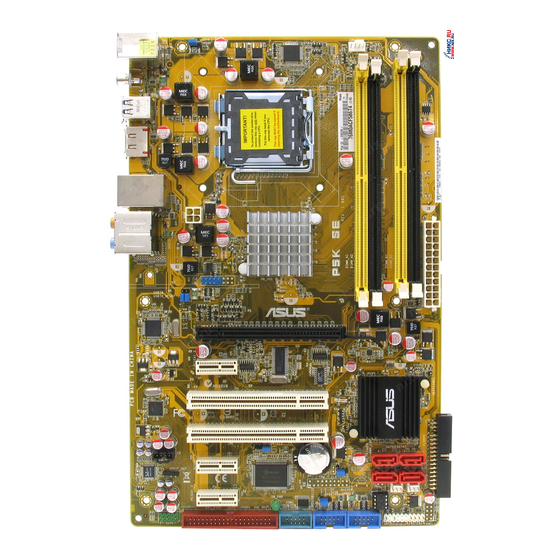
Page 25: Motherboard Layout
Lithium Cell PCIEX1_1 CMOS Power SATA2 SATA1 Super ALC883 SPDIF_OUT CLRTC PWR_FAN PCIEX1_2 USBPW9-12 CHA_FAN BIOS SB_PWR PRI_EIDE COM1 USB1112 USB910 AAFP PANEL Refer to 2.7 Connectors for more information about rear panel connectors and internal connectors. ASUS P5K SE/EPU…
-
Page 26: Layout Contents
2.2.4 Layout contents Slots Page DDR2 DIMM slots 2-13 PCI slots 2-21 PCI Express x1 slot 2-21 PCI Express x16 slots 2-21 Jumper Page Clear RTC RAM (3-pin CLRTC) 2-22 Keyboard power (3-pin PS2_USBPW) 2-23 USB device wake-up (3-pin USBPW1-4, USBPW5-8, USB9-12) 2-23 Rear panel connectors Page…
-
Page 27
• System power LED (2-pin PLED) • Hard disk drive activity LED (2-pin IDE_LED) • System warning speaker (4-pin SPEAKER) • ATX power button/soft-off button (2-pin PWRSW) • Reset button (2-pin RESET) ASUS Q-connector (system panel) 2-35 ASUS P5K SE/EPU… -
Page 28: Central Processing Unit (Cpu)
ASUS will shoulder the cost of repair only if the damage is shipment/transit-related. • Keep the cap after installing the motherboard. ASUS will process Return Merchandise Authorization (RMA) requests only if the motherboard comes with the cap on the LGA775 socket.
-
Page 29: Installing The Cpu
This side of the socket box should face you. To prevent damage to the socket pins, do not remove the PnP cap unless you are installing a CPU. Lift the load lever in the direction of the arrow to a 135º angle. ASUS P5K SE/EPU…
-
Page 30
Lift the load plate with your thumb and forefinger to a 100º angle (A), then push the PnP cap from the load plate window to remove (B). Load plate Alignment key Position the CPU over the socket, making sure that the gold triangle is on the bottom-left corner of the socket then fit the socket… -
Page 31: Installing The Cpu Heatsink And Fan
CPU fan connector. Motherboard hole Fastener Narrow end of the groove Make sure to orient each fastener with the narrow end of the groove pointing outward. (The photo shows the groove shaded for emphasis.) ASUS P5K SE/EPU…
-
Page 32
Push down two fasteners at a time in a diagonal sequence to secure the heatsink and fan assembly in place. Connect the CPU fan cable to the connector on the motherboard labeled CPU_FAN. CPU_FAN ® P5K SE/EPU CPU fan connector Do not forget to connect the CPU fan connector! Hardware monitoring errors can occur if you fail to plug this connector. -
Page 33
Rotate each fastener counterclockwise. Pull up two fasteners at a time in a diagonal sequence to disengage the heatsink and fan assembly from the motherboard. Carefully remove the heatsink and fan assembly from the motherboard. ASUS P5K SE/EPU 2-11… -
Page 34
Rotate each fastener clockwise to ensure correct orientation when reinstalling. Narrow end of the groove The narrow end of the groove should point outward after resetting. (The photo shows the groove shaded for emphasis.) Refer to the documentation in the boxed or stand-alone CPU fan package for detailed information on CPU fan installation. -
Page 35: System Memory
The motherboard comes with four Double Data Rate 2 (DDR2) Dual Inline Memory Modules (DIMM) sockets. The figure illustrates the location of the DDR2 DIMM sockets: ® P5K SE/EPU 240-pin DDR2 DIMM sockets Channel Sockets Channel A DIMM_A1 and DIMM_B1 Channel B DIMM_A2 and DIMM_B2 ASUS P5K SE/EPU 2-13…
-
Page 36: Memory Configurations
2.4.2 Memory configurations You may install 256 MB, 512 MB, 1 GB, and 2 GB unbuffered non-ECC DDR2 DIMMs into the DIMM sockets. Recommended Memory Configurations Sockets Mode DIMM_A1 DIMM_A2 DIMM_B1 DIMM_B2 Populated Single-Channel Populated Dual-channel (1) Populated Populated Dual-channel (2) Populated Populated Populated…
-
Page 37
CM2X1024 — 9136C5D / XMS9105V1.1 • If you install a DDR2-1066 memory module whose SPD is DDR2-800, make sure that you set the DRAM Frequency item in BIOS to [DDR2-1066MHz]. See section 4.4.1 Jumperfree Configuration for details. ASUS P5K SE/EPU 2-15… -
Page 38
P5K SE/EPU Motherboard Qualified Vendors Lists (QVL) DDR2-800 MHz capability DIMM support Chip Size Vendor Chip No. Part No. Brand 512MB KINGSTON K4T51083QC KVR800D2N5/512 • • • 1024MB KINGSTON Heat-Sink Package 4-4-4-12 KHX6400D2LL/1G • • 1024MB KINGSTON Heat-Sink Package 4-4-4-12 KHX6400D2LLK2/1GN •… -
Page 39: Asus P5K Se/Epu
Dual-channel memory configuration. • C*: Supports 4 modules inserted into both the yellow and black slots as two pairs of Dual-channel memory configuration. Visit the ASUS website for the latest DDR2-1066/800/667MHz QVL. ASUS P5K SE/EPU 2-17…
-
Page 40: Installing A Dimm
2.4.3 Installing a DIMM Unplug the power supply before adding or removing DIMMs or other system components. Failure to do so can cause severe damage to both the motherboard and the components. To install a DIMM: DDR2 DIMM notch Unlock a DIMM socket by pressing the retaining clips outward.
-
Page 41: Expansion Slots
IRQ” or that the cards do not need IRQ assignments. Otherwise, conflicts will arise between the two PCI groups, making the system unstable and the card inoperable. Refer to the table on the next page for details. ASUS P5K SE/EPU 2-19…
-
Page 42: Interrupt Assignments
2.5.3 Interrupt assignments Standard function System timer Keyboard controller Re-direct to IRQ#9 IRQ holder for PCI steering* Communications port (COM1)* IRQ holder for PCI steering* Floppy disk controller IRQ holder for PCI steering* System CMOS/Real Time Clock IRQ holder for PCI steering* IRQ holder for PCI steering* IRQ holder for PCI steering* IRQ holder for PCI steering*…
-
Page 43: Pci Slots
PCI Express x1 slot. 2.5.6 PCI Express x16 slot This motherboard supports one PCI Express x16 graphics card that complies with the PCI Express specifications. The figure shows a graphics card installed on the PCI Express x16 slot. ASUS P5K SE/EPU 2-21…
-
Page 44: Clear Rtc Ram
Jumpers Clear RTC RAM (3-pin CLRTC) This jumper allows you to clear the Real Time Clock (RTC) RAM in CMOS. You can clear the CMOS memory of date, time, and system setup parameters by erasing the CMOS RTC RAM data. The onboard button cell battery powers the RAM data in CMOS, which include system setup information such as system passwords.
-
Page 45
500mA on the +5VSB lead for each USB port; otherwise, the system would not power up. • The total current consumed must NOT exceed the power supply capability (+5VSB) whether under normal condition or in sleep mode. ASUS P5K SE/EPU 2-23… -
Page 46: Connectors
Connectors 2.7.1 Rear panel connectors PS/2 keyboard port (purple). This port is for a PS/2 keyboard. LAN (RJ-45) port. Supported by Gigabit LAN controller, this port allows Gigabit connection to a Local Area Network (LAN) through a network hub. Refer to the table below for the LAN port LED indications. Center/Subwoofer port (orange).
-
Page 47
12. Coaxial S/PDIF Out port. This port connects an external audio output device via a coaxial S/PDIF cable. 13. USB 2.0 ports 5 and 6. These two 4-pin Universal Serial Bus (USB) ports are available for connecting USB 2.0 devices. ASUS P5K SE/EPU 2-25… -
Page 48: Internal Connectors
2.7.2 Internal connectors Floppy disk drive connector (34-1 pin FLOPPY) This connector is for the provided floppy disk drive (FDD) signal cable. Insert one end of the cable to this connector, then connect the other end to the signal connector at the back of the floppy disk drive. Pin 5 on the connector is removed to prevent incorrect cable connection when using a FDD cable with a covered Pin 5.
-
Page 49
If any device jumper is set as “Cable-Select,” make sure all other device jumpers have the same setting. ® PRI_EIDE PIN 1 NOTE: Orient the red markings (usually zigzag) on the IDE ribbon cable to PIN 1. P5K SE/EPU IDE connector ASUS P5K SE/EPU 2-27… -
Page 50
ICH9 Serial ATA connectors (7-pin SATA1-4) These connectors are for the Serial ATA signal cables for Serial ATA hard disk drives. SATA3 SATA4 SATA1 SATA2 SATA3 SATA4 ® P5B SATA Connectors SATA2 SATA1 P5K SE/EPU SATA connectors When using the connectors in Standard IDE mode, connect the primary (boot) hard disk drive to the SATA1/2 connector. -
Page 51
Connect the S/PDIF Out module cable to this connector, then install the module to a slot opening at the back of the system chassis. ® SPDIF_OUT P5K SE/EPU Digital audio connector The S/PDIF module is purchased separately. ASUS P5K SE/EPU 2-29… -
Page 52: Usb Connectors
Never connect a 1394 cable to the USB connectors. Doing so will damage the motherboard! You can connect the front panel USB cable to the ASUS Q-Connector (USB, blue) first, and then install the Q-Connector (USB) to the USB connector onboard if your chassis supports front panel USB ports.
-
Page 53
® PWR_FAN CHA_FAN P5K SE/EPU Fan connectors Only the CPU_FAN and CHA_FAN connector support the ASUS Q-FAN 2 feature. Serial port connector (10-1 pin COM1) This connector is for a serial (COM) port. Connect the serial port module cable to this connector, then install the module to a slot opening at the back of the system chassis. -
Page 54: Chassis Intrusion Connector
Chassis intrusion connector (4-1 pin CHASSIS) This connector is for a chassis-mounted intrusion detection sensor or switch. Connect one end of the chassis intrusion sensor or switch cable to this connector. The chassis intrusion sensor or switch sends a high-level signal to this connector when a chassis component is removed or replaced.
-
Page 55
CPU: Intel Pentium Extreme 3.73GHz ® ® Memory: 512 MB DDR2 (x4) Graphics card: ASUS EAX1900XT Parallel ATA device: IDE hard disk drive Serial ATA device: SATA hard disk drive (x2) Optical drive: DVD-RW ASUS P5K SE/EPU 2-33… -
Page 56: System Panel Connector
12. System panel connector (20-8 pin PANEL) This connector supports several chassis-mounted functions. PLED SPEAKER PANEL ® RESET IDE_LED PWRSW Requires an ATX power supply. P5K SE/EPU System panel connector • System power LED (2-pin PLED) This 2-pin connector is for the system power LED. Connect the chassis power LED cable to this connector.
-
Page 57
Q-Connector (system panel) You can use ASUS Q-Connector to connect / disconnect chassis front panel cables by only a few steps. Directions below shows how to install ASUS Q-Connector. Step1. Connect correct front panel to ASUS Q-Connector first. You can refer to the marking on Q-Connector itself to know the detail pin definition. -
Page 58
2-36 Chapter 2: Hardware information… -
Page 59: Chapter 3: Powering Up
This chapter describes the power up sequence, the vocal POST messages, and ways of shutting down the system. Chapter 3: Powering up…
-
Page 60
Chapter summary Starting up for the first time …………3-1 Turning off the computer …………. 3-2 ASUS P5K SE/EPU… -
Page 61: Starting Up For The First Time
One continuous beep followed by three No VGA detected short beeps One continuous beep followed by four Hardware component failure short beeps At power on, hold down the <Delete> key to enter the BIOS Setup. Follow the instructions in Chapter 4. ASUS P5K SE/EPU…
-
Page 62: Turning Off The Computer
Turning off the computer 3.2.1 Using the OS shut down function If you are using Windows ® Click the Start button then select Turn Off Computer. Click the Turn Off button to shut down the computer. The power supply should turn off after Windows ®…
-
Page 63: Chapter 4: Bios Setup
This chapter tells how to change the system settings through the BIOS Setup menus. Detailed descriptions of the BIOS parameters are also provided. Chapter 4: BIOS setup…
-
Page 64
Chapter summary Managing and updating your BIOS ……….4-1 BIOS setup program …………..4-9 Main menu ……………… 4-12 Advanced menu …………….. 4-16 Power menu …………….4-25 Boot menu ……………… 4-29 Tools menu …………….. 4-33 Exit menu ………………4-35 ASUS P5K SE/EPU… -
Page 65: Managing And Updating Your Bios
ASUS Update (Updates the BIOS in Windows environment.) ® ASUS EZ Flash 2 (Updates the BIOS using a floppy disk or USB flash disk.) AFUDOS utility (Updates the BIOS using a bootable floppy disk.) ASUS CrashFree BIOS 3 (Updates the BIOS using a bootable floppy disk, USB flash disk or the motherboard support CD when the BIOS file fails or gets corrupted.)
-
Page 66
To update the BIOS through the Internet: desktop by clicking Start Launch the ASUS Update utility from the Windows ® > Programs > ASUS > ASUSUpdate > ASUSUpdate. The ASUS Update main window appears. Select Update BIOS from the Select the ASUS FTP site nearest… -
Page 67
To update the BIOS through a BIOS file: desktop by clicking Start Launch the ASUS Update utility from the Windows ® > Programs > ASUS > ASUSUpdate > ASUSUpdate. The ASUS Update main window appears. Select Update BIOS from a file option from the drop-down menu, then click Next. -
Page 68: Creating A Bootable Floppy Disk
4.1.2 Creating a bootable floppy disk Do either one of the following to create a bootable floppy disk. DOS environment a. Insert a 1.44MB floppy disk into the drive. b. At the DOS prompt, type format A:/S then press <Enter>. Windows XP environment ®…
-
Page 69: Asus Ez Flash 2 Utility
4.1.3 ASUS EZ Flash 2 utility The ASUS EZ Flash 2 feature allows you to update the BIOS without having to go through the long process of booting from a floppy disk and using a DOS-based utility. The EZ Flash 2 utility is built-in the BIOS chip so it is accessible by pressing <Alt>…
-
Page 70: Afudos Utility
Updating the BIOS file To update the BIOS file using the AFUDOS utility: Visit the ASUS website (www.asus.com) and download the latest BIOS file for the motherboard. Save the BIOS file to a bootable floppy disk. Chapter 4: BIOS setup…
-
Page 71
A:>afudos /iP5KSE.ROM The utility verifies the file and starts updating the BIOS. A:>afudos /iP5KSE.ROM AMI Firmware Update Utility — Version 1.19(ASUS V2.07(03.11.24BB)) Copyright (C) 2002 American Megatrends, Inc. All rights reserved. WARNING!! Do not turn off power during flash BIOS Reading file .. -
Page 72: Asus Crashfree Bios 3 Utility
4.1.5 ASUS CrashFree BIOS 3 utility The ASUS CrashFree BIOS 3 is an auto recovery tool that allows you to restore the BIOS file when it fails or gets corrupted during the updating process. You can update a corrupted BIOS file using the motherboard support CD or a USB flash disk that contains the updated BIOS file.
-
Page 73: Bios Setup Program
The BIOS setup screens shown in this section are for reference purposes only, and may not exactly match what you see on your screen. • Visit the ASUS website (www.asus.com) to download the latest BIOS file for this motherboard. ASUS P5K SE/EPU…
-
Page 74: Bios Menu Screen
4.2.1 BIOS menu screen Menu items Menu bar Configuration fields General help BIOS SETUP UTILITY Main Advanced Power Boot Tools Exit Use [ENTER], [TAB] or System Time [10:55:25] [SHIFT-TAB] to select System Date [Mon 01/28/2008] a field. Legacy Diskette A [1.44M, 3.5 in] Use [+] or [-] to configure system Time.
-
Page 75: Menu Items
Up/Down arrow keys or <Page Up> /<Page Down> keys to display the other items on the screen. 4.2.9 General help Pop-up window At the top right corner of the menu screen Scroll bar is a brief description of the selected item. ASUS P5K SE/EPU 4-11…
-
Page 76: Main Menu
Main menu When you enter the BIOS Setup program, the Main menu screen appears, giving you an overview of the basic system information. Refer to section 4.2.1 BIOS menu screen for information on the menu screen items and how to navigate through them. BIOS SETUP UTILITY Main Advanced…
-
Page 77: Sata 1-4
When set to [Disabled], the data transfer from and to the device occurs one sector at a time. Configuration options: [Disabled] [Auto] PIO Mode [Auto] Selects the PIO mode. Configuration options: [Auto] [0] [1] [2] [3] [4] ASUS P5K SE/EPU 4-13…
-
Page 78: Sata Configuration
DMA Mode [Auto] Selects the DMA mode. Configuration options: [Auto] [SWDMA0] [SWDMA1] [SWDMA2] [MWDMA0] [MWDMA1] [MWDMA2] [UDMA0] [UDMA1] [UDMA2] [UDMA3] [UDMA4] [UDMA5] SMART Monitoring [Auto] Sets the Smart Monitoring, Analysis, and Reporting Technology. Configuration options: [Auto] [Disabled] [Enabled] 32Bit Data Transfer [Enabled] Enables or disables 32-bit data transfer.
-
Page 79: System Information
Available : 1024 MB General Help Save and Exit Exit v02.58 (C)Copyright 1985-2007, American Megatrends, Inc. AMI BIOS Displays the auto-detected BIOS information. Processor Displays the auto-detected CPU specification. System Memory Displays the auto-detected system memory. ASUS P5K SE/EPU 4-15…
-
Page 80: Advanced Menu
Advanced menu The Advanced menu items allow you to change the settings for the CPU and other system devices. Take caution when changing the settings of the Advanced menu items. Incorrect field values can cause the system to malfunction. BIOS SETUP UTILITY Main Advanced Power…
-
Page 81
Allows you to set the DDR2 operating frequency. Configuration options: [Auto] [DDR2-667MHz] [DDR2-800MHz] [DDR2-1066MHz] [DDR2-1200MHz] Selecting a very high DRAM frequency may cause the system to become unstable! If this happens, revert to the default setting. ASUS P5K SE/EPU 4-17… -
Page 82
DRAM Timing Control [Auto] Allows you to set the DRAM timing control. Configuration options: [Auto] [MANUAL] The following items appear when you set the DRAM Timing Control item to [Manual]. CAS# Latency [ 5] Configuration options: [3] [4] [5] [6] RAS# to CAS# Delay [ 5 DRAM Clocks] Configuration options: [3 DRAM Clocks] [4 DRAM Clocks]~[9 DRAM Clocks] [10 DRAM Clocks]… -
Page 83: Ai Net 2
Allows you to enable or disable LAN cable check during POST. When enabled, the menu reports the cable faults or shorts, and displays the point (length) where the faults or shorts are detected. Configuration options: [Disabled] [Enabled] ASUS P5K SE/EPU 4-19…
-
Page 84: Usb Configuration
4.4.3 USB Configuration The items in this menu allows you to change the USB-related features. Select an item then press <Enter> to display the configuration options. BIOS SETUP UTILITY Advanced USB Configuration Options USB Devices Enabled: Disabled None Enhanced USB Functions [Enabled] USB 2.0 Controller [Enabled]…
-
Page 85: Cpu Configuration
Allows you to enable or disable C1E Support. Configuration options: [Disabled] [Enabled] Max CPUID Value Limit [Disabled] Setting this item to [Enabled] allows legacy operating systems to boot even without support for CPUs with extended CPUID functions. Configuration options: [Disabled] [Enabled] ASUS P5K SE/EPU 4-21…
-
Page 86: Chipset
Vanderpool Technology [Enabled] Configuration options: [Enabled] [Disabled] CPU TM Function [Enabled] Configuration options: [Disabled] [Enabled] Execute Disable Bit [Enabled] Allows you to enable or disable the No-Execution Page Protection Technology. Setting this item to [Disabled] forces the XD feature flag to always return to zero (0).
-
Page 87: Onboard Devices Configuration
AC’97 or high-definition audio depending on the audio standard that the front panel audio module supports. Configuration options: [AC97] [HD Audio] Marvell IDE Controller [Enabled] Allows you to disable or enable the onboard Marvell IDE controller. ® Configuration options: [Enabled] [Disabled] ASUS P5K SE/EPU 4-23…
-
Page 88: Pci Pnp
Onboard PCIE GbE LAN [Enabled] Configuration options: [Enabled] [Disabled] LAN Option ROM [Disabled] This item appears only when you enable the previous item. Configuration options: [Disabled] [Enabled] Serial Port1 Address [3F8/IRQ4] Allows you to select the Serial Port1 base address. Configuration options: [Disabled] [3F8/IRQ4] [2F8/IRQ3] [3E8/IRQ4] [2E8/IRQ3] 4.4.7 PCI PnP…
-
Page 89: Power Menu
Allows you to enable or disable the Advanced Configuration and Power Interface (ACPI) support in the Advanced Programmable Interrupt Controller (APIC). When set to Enabled, the ACPI APIC table pointer is included in the RSDT pointer list. Configuration options: [Disabled] [Enabled] ASUS P5K SE/EPU 4-25…
-
Page 90: Apm Configuration
4.5.5 APM Configuration BIOS SETUP UTILITY Power APM Configuration <Enter> to select whether or not to restart the system after AC power loss. Restore on AC Power Loss [Power Off] Power On By RTC Alarm [Disabled] Power On By External Modems [Disabled] Power On By PCI Devices [Disabled]…
-
Page 91: Hardware Monitor
N/A. CPU Q-Fan Control [Disabled] Allows you to enable or disable the CPU Q-Fan controller. Configuration options: [Disabled] [Enabled] The CPU Fan Profile item appears when you enable the CPU Q-Fan Control feature. ASUS P5K SE/EPU 4-27…
-
Page 92
CPU Fan Profile [Optimal] Allows you to set the appropriate performance level of the CPU Q-Fan. When set to [Optimal], the CPU fan automatically adjusts depending on the CPU temperature. Set this item to [Silent Mode] to minimize fan speed for quiet CPU fan operation, or [Performance Mode] to achieve maximum CPU fan speed. -
Page 93: Boot Menu
These items specify the boot device priority sequence from the available devices. The number of device items that appears on the screen depends on the number of devices installed in the system. Configuration options: [1st FLOPPY DRIVE] [Hard Drive] [ATAPI CD-ROM] [Disabled] ASUS P5K SE/EPU 4-29…
-
Page 94: Boot Settings Configuration
Configuration options: [Disabled] [Enabled] Full Screen Logo [Enabled] This allows you to enable or disable the full screen logo display feature. Configuration options: [Disabled] [Enabled] Set this item to [Enabled] to use the ASUS MyLogo2 feature. ™ AddOn ROM Display Mode [Force BIOS] Sets the display mode for option ROM.
-
Page 95: Security
Time Clock (RTC) RAM. See section 2.6 Jumper for information on how to erase the RTC RAM. After you have set a supervisor password, the other items appear to allow you to change other security settings. ASUS P5K SE/EPU 4-31…
-
Page 96: Change User Password
BIOS SETUP UTILITY Boot <Enter> to change Security Settings password. <Enter> again to Supervisor Password :Installed disabled password. User Password :Installed Change Supervisor Password User Access Level [Full Access] Change User Password Clear User Password Password Check [Setup] Select Screen Select Item Enter Change General Help…
-
Page 97: Tools Menu
4.7.1 ASUS EZ Flash 2 Allows you to run ASUS EZ Flash 2. When you press <Enter>, a confirmation message appears. Use the left/right arrow key to select between [Yes] or [No], then press <Enter> to confirm your choice. Please see section 4.1.3 for details.
-
Page 98: Asus O.c. Profile
Start O.C. Profile Allows you to run the utility to save and load CMOS. Press <Enter> to run the utility. ASUSTek O.C. Profile Utility V1.05 Current CMOS Restore CMOS BOARD: P5K SE EPU BOARD: Unknown VER: 0110 VER: Unknown DATE:…
-
Page 99: Exit Menu
Setup menus. When you select this option or if you press <F5>, a confirmation window appears. Select Ok to load default values. Select Exit & Save Changes or make other changes before saving the values to the non-volatile RAM. ASUS P5K SE/EPU 4-35…
-
Page 100
4-36 Chapter 4: BIOS setup… -
Page 101: Chapter 5: Software Support
This chapter describes the contents of the support CD that comes with the motherboard package. Software Chapter 5: support…
-
Page 102
Chapter summary Installing an operating system ……….. 5-1 Support CD information ………….. 5-1 Software information …………..5-8 ASUS P5K SE/EPU… -
Page 103: Installing An Operating System
The contents of the support CD are subject to change at any time without notice. Visit the ASUS website (www.asus.com) for updates. 5.2.1 Running the support CD Place the support CD to the optical drive.
-
Page 104: Drivers Menu
6111 Serial ATA controller driver. ® USB 2.0 Driver Installs the Universal Serial Bus 2.0 (USB 2.0) driver. AI Gear 3+ Driver Installs the EPU and AI Gear 3 driver. Install this driver before the ASUS AI Suite utility. Chapter 5: Software support…
-
Page 105: Utilities Menu
Installs all of the utilities through the Installation Wizard. ASUS Update Allows you to download the latest version of the BIOS from the ASUS website. Before using the ASUS Update, make sure that you have an Internet connection so you can connect to the ASUS website.
-
Page 106
You can also install the following utilities from the ASUS Superb Software Library CD. ADOBE Acrobat Reader V7.0 Installs the Adobe Acrobat Reader that allows you to open, view, and print ® ® documents in Portable Document Format (PDF). Microsoft DirectX 9.0c Installs the Microsoft DirectX 9.0 driver. -
Page 107: Manual Menu
Reader from the ASUS Superb Software Library CD before ® ® opening a user manual file. 5.2.5 ASUS Contact information Click the Contact tab to display the ASUS contact information. You can also find this information on the inside front cover of this user guide. ASUS P5K SE/EPU…
-
Page 108: Other Information
5.2.6 Other information The icons on the top right corner of the screen give additional information on the motherboard and the contents of the support CD. Click an icon to display the specified information. Motherboard Info Displays the general specifications of the motherboard. Browse this CD Displays the support CD contents in graphical format.
-
Page 109: Technical Support Form
Technical support Form Displays the ASUS Technical Support Request Form that you have to fill out when requesting technical support. Filelist Displays the contents of the support CD and a brief description of each in text format. ASUS P5K SE/EPU…
-
Page 110: Software Information
5.3.1 ASUS MyLogo2™ The ASUS MyLogo2™ utility lets you customize the boot logo. The boot logo is the image that appears on screen during the Power-On Self-Tests (POST). The ASUS MyLogo2™ is automatically installed when you install the ASUS Update utility from the Support CD.
-
Page 111
Ratio box. When the screen returns to the ASUS Update utility, flash the original BIOS to load the new boot logo. 10. After flashing the BIOS, restart the computer to display the new boot logo during POST. -
Page 112: Audio Configurations
5.3.2 Audio configurations The Realtek ALC883 audio CODEC provides 8-channel audio capability to deliver ® the ultimate audio experience on your computer. The software provides Jack- Sensing function, S/PDIF Out support, and interrupt capability. The ALC883 also includes the Realtek ®…
-
Page 113: Configuration Options
Click the shortcut buttons or the drop-down menus for options on changing the acoustic environment, adjust the equalizer, or set the karaoke to your desired settings. Click to effect the Sound Effect settings and exit. ASUS P5K SE/EPU 5-11…
-
Page 114
Mixer The Mixer option allows you to configure audio output (playback) volume and audio input (record) volume. To set the mixer options: From the Realtek HD Audio Manager, click the Mixer tab. Turn the volume buttons to adjust the Playback and/or Record volume. -
Page 115
From the Realtek HD Audio Manager, click the 3D Audio Demo tab. Click the option buttons to change the sound, moving path, or environment settings. Click to test your settings. Click to effect the 3D Audio Demo settings and exit. ASUS P5K SE/EPU 5-13… -
Page 116: Asus Pc Probe Ii
To launch the PC Probe II from the Windows ® > ASUS > PC Probe II > PC Probe II v1.xx.xx. The PC Probe II main window appears. After launching the application, the PC Probe II icon appears in the Windows ®…
-
Page 117
When a system sensor detects a problem, the main window right handle turns red, as the illustrations below show. When displayed, the monitor panel for that sensor also turns red. Refer to the Monitor panels section for details. ASUS P5K SE/EPU 5-15… -
Page 118
Hardware monitor panels The hardware monitor panels display the current value of a system sensor such as fan rotation, CPU temperature, and voltages. The hardware monitor panels come in two display modes: hexagonal (large) and rectangular (small). When you check the Enable Monitoring Panel option from the Preference section, the monitor panels appear on your computer’s desktop. -
Page 119
You can enlarge or reduce the browser size by dragging the bottom right corner of the browser. DMI browser Click to display the DMI (Desktop Management Interface) browser. This browser displays various desktop and system information. Click the plus sign (+) before DMI Information to display the available information. ASUS P5K SE/EPU 5-17… -
Page 120
PCI browser Click to display the PCI (Peripheral Component Interconnect) browser. This browser provides information on the PCI devices installed on your system. Click the plus sign (+) before the PCI Information item to display available information. Usage The Usage browser displays real-time information on the CPU, hard disk drive space, and memory usage. -
Page 121
The Preference tab allows you to customize sensor alerts, or change the temperature scale. Loads the default Loads your saved threshold values for Cancels or configuration each sensor ignores your changes Applies your Saves your changes configuration ASUS P5K SE/EPU 5-19… -
Page 122: Asus Ai Suite
ASUS AI Suite allows you to launch AI Gear 3 , AI Booster, AI Nap, and Q-Fan 2 utilities easily. Install the AI Gear 3+ Driver before the ASUS AI Suite utility. Otherwise, the ASUS AI Suite will not function properly. Installing AI Suite To install AI Suite on your computer: Place the support DVD to the optical drive.
-
Page 123
Displays the CPU/ system temperature, CPU/memory/PCIE voltage, and CPU/ chassis fan speed Displays the FSB/CPU frequency Click on right corner of the expanded window to switch the temperature from degrees Centigrade to degrees Fahrenheit. ASUS P5K SE/EPU 5-21… -
Page 124: Asus Epu Utility — Ai Gear 3
After installing ASUS AI Suite from the bundled support DVD, you can launch ASUS AI Gear 3 by double-clicking the AI Suite icon on your Windows OS taskbar and then click the AI Gear 3 button on the AI Suite main window.
-
Page 125
Electricity Savings Calculator window. You may reset the Click time for the calculator to start counting. Click to reset the time the calculator starts Displays the electricity saved since the time was reset ASUS P5K SE/EPU 5-23… -
Page 126: Asus Ai Nap
5.3.6 ASUS AI Nap This feature allows you to minimize the power consumption of your computer whenever you are away. Enable this feature for minimum power consumption and a more quiet system operation. After installing AI Suite from the bundled support CD, you can launch the utility by double-clicking the AI Suite icon on the Windows OS taskbar and click the AI Nap button on the AI Suite main window.
-
Page 127: Asus Q-Fan 2
5.3.7 ASUS Q-Fan 2 This ASUS Q-Fan 2 Control feature allows you to set the appropriate performance level of the CPU Q-Fan 2 or the Chassis Q-Fan 2 for more efficient system operation. After enabling the Q-Fan 2 function, the fans can be set to automatically adjust depending on the temperature, to decrease fan speed, or to achieve the maximum fan speed.
-
Page 128: Asus Ai Booster
5.3.8 ASUS AI Booster The ASUS AI Booster application allows you to overclock the CPU speed in WIndows environment without the hassle of booting the BIOS. ® After installing AI Suite from the bundled support CD, you can launch the utility…
-
Page 129: Appendix: Cpu Features
The Appendix describes the CPU features and technologies that the motherboard supports. Appendix: CPU features…
-
Page 130: A.1 Intel ® Em64T
Chapter summary Intel ® EM64T ………………A-1 Enhanced Intel SpeedStep Technology (EIST) ……A-1 ® Intel Hyper-Threading Technology ………..A-3 ® ASUS P5K SE/EPU…
-
Page 131: Intel ® Em64T
32-bit operating systems. • The motherboard comes with a BIOS file that supports EM64T. You can download the latest BIOS file from the ASUS website (www.asus.com/ support/download/) if you need to update the BIOS file. See Chapter 4 for details.
-
Page 132: Using The Eist
A.2.2 Using the EIST To use the EIST feature: Turn on the computer, then enter the BIOS Setup. Go to the Advanced Menu, highlight CPU Configuration, then press <Enter>. Set the Intel(R) SpeedStep Technology item to [Automatic], then press <Enter>. Press <F10>…
-
Page 133: Intel ® Hyper-Threading Technology
Power up the system and enter the BIOS Setup. Under the Advanced Menu, make sure that the item Hyper-Threading Technology is set to [Enabled]. The BIOS item appears only if you installed a CPU that supports Hyper-Threading Technology. Restart the computer. ASUS P5K SE/EPU…
-
Page 134
Appendix: CPU features…
-
Page 1
P5K SE… -
Page 2
Product warranty or service will not be extended if: (1) the product is repaired, modified or altered, unless such repair, modification of alteration is authorized in writing by ASUS; or (2) the serial number of the product is defaced or missing. -
Page 3: Table Of Contents
Product introduction Welcome! ………………1-1 Package contents …………….. 1-1 Special features …………….1-2 1.3.1 Product highlights …………1-2 1.3.2 ASUS AI Lifestyle features ……….1-4 1.3.3 ASUS Stylish features …………. 1-5 1.3.4 ASUS Intelligent Overclocking features ……1-6 Chapter2: Hardware information Before you proceed …………..
-
Page 4
4.1.1 ASUS Update utility …………4-1 4.1.2 Creating a bootable floppy disk ……..4-4 4.1.3 ASUS EZ Flash 2 utility ……….. 4-5 4.1.4 AFUDOS utility …………..4-6 4.1.5 ASUS CrashFree BIOS 3 utility ……..4-8 BIOS setup program …………..4-9 4.2.1… -
Page 5
4.6.2 Boot Settings Configuration ………. 4-30 4.6.3 Security …………….. 4-31 Tools menu …………….. 4-33 4.7.1 ASUS EZ Flash 2 …………4-33 4.7.2 ASUS O.C. Profile …………4-34 Exit menu ………………4-35 Chapter5: Software support Installing an operating system ……….. 5-1 5.2.1… -
Page 6
Contents 5.3.5 ASUS AI Gear2 …………. 5-22 5.3.6 ASUS AI Nap …………..5-23 5.3.7 ASUS Q-Fan 2 ………….. 5-24 5.3.8 ASUS AI Booster …………5-25 Appendix: CPU features Intel EM64T ………………A-1 ® Enhanced Intel SpeedStep Technology (EIST) ……A-1 ® A.2.1 System requirements …………A-1… -
Page 7: Notices
Notices Federal Communications Commission Statement This device complies with Part 15 of the FCC Rules. Operation is subject to the following two conditions: • This device may not cause harmful interference, and • This device must accept any interference received including interference that may cause undesired operation.
-
Page 8: Safety Information
Safety information Electrical safety • To prevent electrical shock hazard, disconnect the power cable from the electrical outlet before relocating the system. • When adding or removing devices to or from the system, ensure that the power cables for the devices are unplugged before the signal cables are connected.
-
Page 9: About This Guide
Refer to the following sources for additional information and for product and software updates. ASUS websites The ASUS website provides updated information on ASUS hardware and software products. Refer to the ASUS contact information. Optional documentation Your product package may include optional documentation, such as warranty flyers, that may have been added by your dealer.
-
Page 10: Conventions Used In This Guide
Conventions used in this guide To make sure that you perform certain tasks properly, take note of the following symbols used throughout this manual. DANGER/WARNING: Information to prevent injury to yourself when trying to complete a task. CAUTION: Information to prevent damage to the components when trying to complete a task.
-
Page 11: P5K Se Specifications Summary
— Supports up to 8 GB system memory * The chipset officially supports the memory frequency up to DDR2 800MHz. Tuned by the ASUS Super Memspeed Technology, this motherboard natively supports up to DDR2 1066MHz. Refer to www.asus.com or this user manual for the Memory QVL (Qualified Vendors Lists).
-
Page 12
— Memory tuning from 667MHz to 1333MHz for DDR2 — PCI-E frequency tuning from 100MHz to 150MHz at 1 MHz increment Overclocking protection: — ASUS C.P.R. (CPU Parameter Recall) Rear panel connectors 1 x PS/2 keyboard port 1 x External Serial ATA port… -
Page 13
System panel connector (Q-Connector) BIOS features 8 Mb Flash ROM, AMI BIOS, PnP, DMI 2.0, WfM 2.0, SM BIOS 2.3, ACPI 2.0a, ASUS EZ Flash 2, ASUS CrashFree BIOS 3 Manageability WfM 2.0, DMI 2.0, WOL by PME, WOR by PME, PXE… -
Page 15: Chapter1: Product Introduction
This chapter describes the motherboard features and the new technologies it supports. Product introduction…
-
Page 16
Chapter summary Welcome! ………………1-1 Package contents …………….. 1-1 Special features …………….1-2 ASUS P5K SE… -
Page 17: Welcome
® The motherboard delivers a host of new features and latest technologies, making it another standout in the long line of ASUS quality motherboards! Before you start installing the motherboard, and hardware devices on it, check the items in your package with the list below.
-
Page 18: Special Features
Green ASUS This motherboard and its packaging comply with the European Union’s Restriction on the use of Hazardous Substances (RoHS). This is in line with the ASUS vision of creating environment-friendly and recyclable products/packaging to safeguard consumers’ health while minimizing the impact on the environment.
-
Page 19: High Definition Audio
ASUS Super Memspeed Technology To attain top performance, ASUS has managed to break through current FSB and DRAM ratio proportions by utilizing Super Memspeed Technology–the latest technology that provides even more precise overclocking options to unleash the true potential of DDR2 memory. The DDR2 Mode maximizes system performance by eliminating the bottleneck when overclocking both the CPU and memory–…
-
Page 20: Asus Ai Lifestyle Features
1.3.2 ASUS AI Lifestyle features ASUS Quiet Thermal Solution ASUS Quiet Thermal solution makes system more stable and enhances the overclocking capability. AI Gear 2 AI Gear 2 allows you to choose profiles to adjust the CPU frequency and Vcore voltage to minimize system noise and power consumption. You can change the mode in real-time in the operating system to max power saving mode and save up to 50% power when using word processing applications.
-
Page 21: Asus Stylish Features
Smart Support CD It provides a checklist to allow the user to see which drivers are already installed, as well as those that aren’t. When using ASUS PC Probe II, you can easily see the critical parts of the computer.
-
Page 22: Asus Intelligent Overclocking Features
1.3.4 ASUS Intelligent Overclocking features AI Booster The ASUS AI Booster allows you to overclock the CPU speed in Windows environment without the hassle of booting the BIOS. See page 5-26 for details. Precision Tweaker This feature allows you to fine tune the CPU/memory voltage and gradually increase the memory Front Side Bus (FSB) and PCI Express frequency at 1MHz increment to achieve maximum system performance.
-
Page 23: Chapter2: Hardware Information
This chapter lists the hardware setup procedures that you have to perform when installing system components. It includes description of the jumpers and connectors on the motherboard. Hardware information…
-
Page 24
Chapter summary Before you proceed …………..2-1 Motherboard overview …………..2-2 Central Processing Unit (CPU) ……….. 2-6 System memory …………….. 2-13 Expansion slots …………….2-19 Jumpers ………………2-22 Connectors …………….. 2-24 ASUS P5K SE… -
Page 25: Before You Proceed
The illustration below shows the location of the onboard LED. SB_PWR ® Standby Powered P5K SE Onboard LED Power ASUS P5K SE…
-
Page 26: Motherboard Overview
Motherboard overview Before you install the motherboard, study the configuration of your chassis to ensure that the motherboard fits into it. Make sure to unplug the power cord before installing or removing the motherboard. Failure to do so can cause you physical injury and damage motherboard components.
-
Page 27: Motherboard Layout
Lithium Cell PCIEX1_1 CMOS Power SATA2 SATA1 Super ALC883 SPDIF_OUT CLRTC PWR_FAN PCIEX1_2 USBPW9-12 CHA_FAN BIOS SB_PWR PRI_EIDE COM1 USB1112 USB910 AAFP PANEL Refer to 2.7 Connectors for more information about rear panel connectors and internal connectors. ASUS P5K SE…
-
Page 28: Layout Contents
2.2.4 Layout contents Slots Page DDR2 DIMM slots 2-13 PCI slots 2-21 PCI Express x1 slot 2-21 PCI Express x16 slots 2-21 Jumper Page Clear RTC RAM (3-pin CLRTC) 2-22 Keyboard power (3-pin PS2_USBPW) 2-23 USB device wake-up (3-pin USBPW1-4, USBPW5-8, USB9-12) 2-23 Rear panel connectors Page…
-
Page 29
• System power LED (2-pin PLED) • Hard disk drive activity LED (2-pin IDE_LED) • System warning speaker (4-pin SPEAKER) • ATX power button/soft-off button (2-pin PWRSW) • Reset button (2-pin RESET) ASUS Q-connector (system panel) 2-35 ASUS P5K SE… -
Page 30: Central Processing Unit (Cpu)
ASUS will shoulder the cost of repair only if the damage is shipment/transit-related. • Keep the cap after installing the motherboard. ASUS will process Return Merchandise Authorization (RMA) requests only if the motherboard comes with the cap on the LGA775 socket.
-
Page 31: Installing The Cpu
This side of the socket box should face you. To prevent damage to the socket pins, do not remove the PnP cap unless you are installing a CPU. Lift the load lever in the direction of the arrow to a 135º angle. ASUS P5K SE…
-
Page 32
Lift the load plate with your thumb and forefinger to a 100º angle (A), then push the PnP cap from the load plate window to remove (B). Load plate Alignment key Position the CPU over the socket, making sure that the gold triangle is on the bottom-left corner of the socket then fit the socket… -
Page 33: Installing The Cpu Heatsink And Fan
CPU fan connector. Motherboard hole Fastener Narrow end of the groove Make sure to orient each fastener with the narrow end of the groove pointing outward. (The photo shows the groove shaded for emphasis.) ASUS P5K SE…
-
Page 34
Push down two fasteners at a time in a diagonal sequence to secure the heatsink and fan assembly in place. Connect the CPU fan cable to the connector on the motherboard labeled CPU_FAN. CPU_FAN ® P5K SE CPU fan connector Do not forget to connect the CPU fan connector! Hardware monitoring errors can occur if you fail to plug this connector. -
Page 35
Rotate each fastener counterclockwise. Pull up two fasteners at a time in a diagonal sequence to disengage the heatsink and fan assembly from the motherboard. Carefully remove the heatsink and fan assembly from the motherboard. ASUS P5K SE 2-11… -
Page 36
Rotate each fastener clockwise to ensure correct orientation when reinstalling. Narrow end of the groove The narrow end of the groove should point outward after resetting. (The photo shows the groove shaded for emphasis.) Refer to the documentation in the boxed or stand-alone CPU fan package for detailed information on CPU fan installation. -
Page 37: System Memory
Sockets Channel A DIMM_A1 and DIMM_B1 Channel B DIMM_A2 and DIMM_B2 • This chipset officially supports DDR2-800 MHz. With the ASUS Super Memspeed Technology, this motherboard natively supports up to DDR2-1066 MHz. See the table below. DDR2 1333 1066* 1333…
-
Page 38: Memory Configurations
2.4.2 Memory configurations You may install 256 MB, 512 MB, 1 GB, and 2 GB unbuffered non-ECC DDR2 DIMMs into the DIMM sockets. Recommended Memory Configurations Sockets Mode DIMM_A1 DIMM_A2 DIMM_B1 DIMM_B2 Populated Single-Channel Populated Dual-channel (1) Populated Populated Dual-channel (2) Populated Populated Populated…
-
Page 39
Dual-channel memory configuration. • C*: Supports 4 modules inserted into both the yellow and black slots as two pairs of Dual-channel memory configuration. Visit the ASUS website for the latest DDR2-1066/800/667MHz QVL. ASUS P5K SE 2-15… -
Page 40
P5K SE Motherboard Qualified Vendors Lists (QVL) DDR2-800 MHz capability DIMM support Chip Size Vendor Chip No. Part No. Brand 512MB KINGSTON K4T51083QC KVR800D2N5/512 • • • 1024MB KINGSTON Heat-Sink Package 4-4-4-12 KHX6400D2LL/1G • • 1024MB KINGSTON Heat-Sink Package 4-4-4-12 KHX6400D2LLK2/1GN •… -
Page 41
• • 1024MB Hynix HY5PS12821CFP-Y5 Hynix HYMP512U64CP8-Y5 • 256MB CORSAIR MIII00605 VS256MB667D2 • 2048MB NANYA NT5TU128M8BJ-3C NANYA NT2GT64U8HB0JY-3C • • 512MB NANYA NT5TU64M8BE-3C NANYA NT512T64U88B0BY-3C • 512MB A3R12E3GEF637BLC5N AL6E8E63B-6E1K • • • 1024MB A3R12E3GEF637BLC5N AL7E8E63B-6E1K • ASUS P5K SE 2-17… -
Page 42: Installing A Dimm
2.4.3 Installing a DIMM Unplug the power supply before adding or removing DIMMs or other system components. Failure to do so can cause severe damage to both the motherboard and the components. To install a DIMM: DDR2 DIMM notch Unlock a DIMM socket by pressing the retaining clips outward.
-
Page 43: Expansion Slots
IRQ” or that the cards do not need IRQ assignments. Otherwise, conflicts will arise between the two PCI groups, making the system unstable and the card inoperable. Refer to the table on the next page for details. ASUS P5K SE 2-19…
-
Page 44: Interrupt Assignments
2.5.3 Interrupt assignments Standard function System timer Keyboard controller Re-direct to IRQ#9 IRQ holder for PCI steering* Communications port (COM1)* IRQ holder for PCI steering* Floppy disk controller System CMOS/Real Time Clock Microsoft ACPI-Compliant System IRQ holder for PCI steering* IRQ holder for PCI steering* Numeric data processor Intel(R) ICH9 Family SMbus Controller * These IRQs are usually available for PCI devices.
-
Page 45: Pci Slots
PCI Express x1 slot. 2.5.6 PCI Express x16 slot This motherboard supports one PCI Express x16 graphics card that complies with the PCI Express specifications. The figure shows a graphics card installed on the PCI Express x16 slot. ASUS P5K SE 2-21…
-
Page 46: Jumper
Jumpers Clear RTC RAM (3-pin CLRTC) This jumper allows you to clear the Real Time Clock (RTC) RAM in CMOS. You can clear the CMOS memory of date, time, and system setup parameters by erasing the CMOS RTC RAM data. The onboard button cell battery powers the RAM data in CMOS, which include system setup information such as system passwords.
-
Page 47
500mA on the +5VSB lead for each USB port; otherwise, the system would not power up. • The total current consumed must NOT exceed the power supply capability (+5VSB) whether under normal condition or in sleep mode. ASUS P5K SE 2-23… -
Page 48: Connectors
Connectors 2.7.1 Rear panel connectors PS/2 keyboard port (purple). This port is for a PS/2 keyboard. LAN (RJ-45) port. Supported by Gigabit LAN controller, this port allows Gigabit connection to a Local Area Network (LAN) through a network hub. Refer to the table below for the LAN port LED indications. Center/Subwoofer port (orange).
-
Page 49
12. Coaxial S/PDIF Out port. This port connects an external audio output device via a coaxial S/PDIF cable. 13. USB 2.0 ports 5 and 6. These two 4-pin Universal Serial Bus (USB) ports are available for connecting USB 2.0 devices. ASUS P5K SE 2-25… -
Page 50: Internal Connectors
2.7.2 Internal connectors Floppy disk drive connector (34-1 pin FLOPPY) This connector is for the provided floppy disk drive (FDD) signal cable. Insert one end of the cable to this connector, then connect the other end to the signal connector at the back of the floppy disk drive. Pin 5 on the connector is removed to prevent incorrect cable connection when using a FDD cable with a covered Pin 5.
-
Page 51
If any device jumper is set as “Cable-Select,” make sure all other device jumpers have the same setting. ® PRI_EIDE PIN 1 NOTE: Orient the red markings (usually zigzag) on the IDE ribbon cable to PIN 1. P5K SE IDE connector ASUS P5K SE 2-27… -
Page 52
ICH9 Serial ATA connectors (7-pin SATA1-4) These connectors are for the Serial ATA signal cables for Serial ATA hard disk drives. SATA1 SATA2 SATA3 SATA4 SATA4 SATA3 ® P5B SATA Connectors P5K SE SATA connectors SATA2 SATA1 When using the connectors in Standard IDE mode, connect the primary (boot) hard disk drive to the SATA1/2 connector. -
Page 53
Connect the S/PDIF Out module cable to this connector, then install the module to a slot opening at the back of the system chassis. ® SPDIF_OUT P5K SE Digital audio connector The S/PDIF module is purchased separately. ASUS P5K SE 2-29… -
Page 54
Never connect a 1394 cable to the USB connectors. Doing so will damage the motherboard! You can connect the front panel USB cable to the ASUS Q-Connector (USB, blue) first, and then install the Q-Connector (USB) to the USB connector onboard if your chassis supports front panel USB ports. -
Page 55
® PWR_FAN CHA_FAN P5K SE Fan connectors Only the CPU_FAN and CHA_FAN connector support the ASUS Q-FAN 2 feature. Serial port connector (10-1 pin COM1) This connector is for a serial (COM) port. Connect the serial port module cable to this connector, then install the module to a slot opening at the back of the system chassis. -
Page 56
Chassis intrusion connector (4-1 pin CHASSIS) This connector is for a chassis-mounted intrusion detection sensor or switch. Connect one end of the chassis intrusion sensor or switch cable to this connector. The chassis intrusion sensor or switch sends a high-level signal to this connector when a chassis component is removed or replaced. -
Page 57
CPU: Intel Pentium Extreme 3.73GHz ® ® Memory: 512 MB DDR2 (x4) Graphics card: ASUS EAX1900XT Parallel ATA device: IDE hard disk drive Serial ATA device: SATA hard disk drive (x2) Optical drive: DVD-RW ASUS P5K SE 2-33… -
Page 58: System Panel Connector
12. System panel connector (20-8 pin PANEL) This connector supports several chassis-mounted functions. PLED SPEAKER PANEL ® RESET IDE_LED PWRSW Requires an ATX power supply. P5K SE System panel connector • System power LED (2-pin PLED) This 2-pin connector is for the system power LED. Connect the chassis power LED cable to this connector.
-
Page 59: Q-Connector
Q-Connector (system panel) You can use ASUS Q-Connector to connect / disconnect chassis front panel cables by only a few steps. Directions below shows how to install ASUS Q-Connector. Step1. Connect correct front panel to ASUS Q-Connector first. You can refer to the marking on Q-Connector itself to know the detail pin definition.
-
Page 60
2-36 Chapter 2: Hardware information… -
Page 61: Chapter3: Powering Up
This chapter describes the power up sequence, the vocal POST messages, and ways of shutting down the system. Powering up…
-
Page 62
Chapter summary Starting up for the first time …………3-1 Turning off the computer …………. 3-2 ASUS P5K SE… -
Page 63: Starting Up For The First Time
One continuous beep followed by three No VGA detected short beeps One continuous beep followed by four Hardware component failure short beeps At power on, hold down the <Delete> key to enter the BIOS Setup. Follow the instructions in Chapter 4. ASUS P5K SE…
-
Page 64: Turning Off The Computer
Turning off the computer 3.2.1 Using the OS shut down function If you are using Windows ® Click the Start button then select Turn Off Computer. Click the Turn Off button to shut down the computer. The power supply should turn off after Windows ®…
-
Page 65: Chapter4: Bios Setup
This chapter tells how to change the system settings through the BIOS Setup menus. Detailed descriptions of the BIOS parameters are also provided. BIOS setup…
-
Page 66
Chapter summary Managing and updating your BIOS ……….4-1 BIOS setup program …………..4-9 Main menu ……………… 4-12 Advanced menu …………….. 4-16 Power menu …………….4-25 Boot menu ……………… 4-29 Tools menu …………….. 4-33 Exit menu ………………4-35 ASUS P5K SE… -
Page 67: Managing And Updating Your Bios
ASUS Update (Updates the BIOS in Windows environment.) ® ASUS EZ Flash 2 (Updates the BIOS using a floppy disk or USB flash disk.) ASUS AFUDOS (Updates the BIOS using a bootable floppy disk.) ASUS CrashFree BIOS 3 (Updates the BIOS using a bootable floppy disk, USB flash disk or the motherboard support CD when the BIOS file fails or gets corrupted.)
-
Page 68
To update the BIOS through the Internet: desktop by clicking Start Launch the ASUS Update utility from the Windows ® > Programs > ASUS > ASUSUpdate > ASUSUpdate. The ASUS Update main window appears. Select Update BIOS from the Select the ASUS FTP site nearest… -
Page 69
To update the BIOS through a BIOS file: desktop by clicking Start Launch the ASUS Update utility from the Windows ® > Programs > ASUS > ASUSUpdate > ASUSUpdate. The ASUS Update main window appears. Select Update BIOS from a file option from the drop-down menu, then click Next. -
Page 70: Creating A Bootable Floppy Disk
4.1.2 Creating a bootable floppy disk Do either one of the following to create a bootable floppy disk. DOS environment a. Insert a 1.44MB floppy disk into the drive. b. At the DOS prompt, type format A:/S then press <Enter>. Windows XP environment ®…
-
Page 71: Asus Ez Flash 2 Utility
4.1.3 ASUS EZ Flash 2 utility The ASUS EZ Flash 2 feature allows you to update the BIOS without having to go through the long process of booting from a floppy disk and using a DOS-based utility. The EZ Flash 2 utility is built-in the BIOS chip so it is accessible by pressing <Alt>…
-
Page 72: Afudos Utility
Updating the BIOS file To update the BIOS file using the AFUDOS utility: Visit the ASUS website (www.asus.com) and download the latest BIOS file for the motherboard. Save the BIOS file to a bootable floppy disk. Chapter 4: BIOS setup…
-
Page 73
A:>afudos /iP5KSE.ROM The utility verifies the file and starts updating the BIOS. A:>afudos /iP5KSE.ROM AMI Firmware Update Utility — Version 1.19(ASUS V2.07(03.11.24BB)) Copyright (C) 2002 American Megatrends, Inc. All rights reserved. WARNING!! Do not turn off power during flash BIOS Reading file .. -
Page 74: Asus Crashfree Bios 3 Utility
4.1.5 ASUS CrashFree BIOS 3 utility The ASUS CrashFree BIOS 3 is an auto recovery tool that allows you to restore the BIOS file when it fails or gets corrupted during the updating process. You can update a corrupted BIOS file using the motherboard support CD or a USB flash disk that contains the updated BIOS file.
-
Page 75: Bios Setup Program
The BIOS setup screens shown in this section are for reference purposes only, and may not exactly match what you see on your screen. • Visit the ASUS website (www.asus.com) to download the latest BIOS file for this motherboard. ASUS P5K SE…
-
Page 76: Bios Menu Screen
4.2.1 BIOS menu screen Menu items Menu bar Configuration fields General help BIOS SETUP UTILITY Main Advanced Power Boot Tools Exit Use [ENTER], [TAB] or System Time [10:55:25] [SHIFT-TAB] to select System Date [Fri 05/07/2007] a field. Legacy Diskette A [1.44M, 3.5 in] Use [+] or [-] to configure system Time.
-
Page 77: Menu Items
Up/Down arrow keys or <Page Up> /<Page Down> keys to display the other items on the screen. 4.2.9 General help Pop-up window At the top right corner of the menu screen Scroll bar is a brief description of the selected item. ASUS P5K SE 4-11…
-
Page 78: Main Menu
Main menu When you enter the BIOS Setup program, the Main menu screen appears, giving you an overview of the basic system information. Refer to section 4.2.1 BIOS menu screen for information on the menu screen items and how to navigate through them. BIOS SETUP UTILITY Main Advanced…
-
Page 79: Sata 1~4
When set to [Disabled], the data transfer from and to the device occurs one sector at a time. Configuration options: [Disabled] [Auto] PIO Mode [Auto] Selects the PIO mode. Configuration options: [Auto] [0] [1] [2] [3] [4] ASUS P5K SE 4-13…
-
Page 80: Sata Configuration
DMA Mode [Auto] Selects the DMA mode. Configuration options: [Auto] [SWDMA0] [SWDMA1] [SWDMA2] [MWDMA0] [MWDMA1] [MWDMA2] [UDMA0] [UDMA1] [UDMA2] [UDMA3] [UDMA4] [UDMA5] SMART Monitoring [Auto] Sets the Smart Monitoring, Analysis, and Reporting Technology. Configuration options: [Auto] [Disabled] [Enabled] 32Bit Data Transfer [Enabled] Enables or disables 32-bit data transfer.
-
Page 81: System Information
Available : 1024 MB General Help Save and Exit Exit v02.58 (C)Copyright 1985-2007, American Megatrends, Inc. AMI BIOS Displays the auto-detected BIOS information. Processor Displays the auto-detected CPU specification. System Memory Displays the auto-detected system memory. ASUS P5K SE 4-15…
-
Page 82: Advanced Menu
Advanced menu The Advanced menu items allow you to change the settings for the CPU and other system devices. Take caution when changing the settings of the Advanced menu items. Incorrect field values can cause the system to malfunction. BIOS SETUP UTILITY Main Advanced Power…
-
Page 83
DRAM Frequency [Auto] Allows you to set the DDR2 operating frequency. Configuration options: [Auto] [DDR2-667MHz] [DDR2-800MHz] Selecting a very high DRAM frequency may cause the system to become unstable! If this happens, revert to the default setting. ASUS P5K SE 4-17… -
Page 84
DRAM Timing Control [Auto] Allows you to set the DRAM timing control. Configuration options: [Auto] [MANUAL] The following items appear when you set the DRAM Timing Control item to [Manual]. CAS# Latency [ 5] Configuration options: [3] [4] [5] [6] RAS# to CAS# Delay [ 5 DRAM Clocks] Configuration options: [3 DRAM Clocks] [4 DRAM Clocks]~[9 DRAM Clocks] [10 DRAM Clocks]… -
Page 85
Configuration options: [Auto] [1.80V] [1.85V] [1.90V] [1.95V] [2.00V] [2.05V] [2.10V] [2.15V] [2.20V] [2.25V] [2.30V] [2.35V] [2.40V] [2.45V] [2.50V] [2.55V] [2.60V] Refer to the DDR2 documentation before adjusting the memory voltage. Setting a very high memory voltage may damage the memory module(s)! ASUS P5K SE 4-19… -
Page 86: Usb Configuration
4.4.2 USB Configuration The items in this menu allows you to change the USB-related features. Select an item then press <Enter> to display the configuration options. BIOS SETUP UTILITY Advanced USB Configuration Options USB Devices Enabled: Disabled None Enhanced USB Functions [Enabled] USB 2.0 Controller [Enabled]…
-
Page 87: Cpu Configuration
Allows you to enable or disable C1E Support. Configuration options: [Disabled] [Enabled] Max CPUID Value Limit [Disabled] Setting this item to [Enabled] allows legacy operating systems to boot even without support for CPUs with extended CPUID functions. Configuration options: [Disabled] [Enabled] ASUS P5K SE 4-21…
-
Page 88: Chipset
Vanderpool Technology [Enabled] Configuration options: [Enabled] [Disabled] CPU TM Function [Enabled] Configuration options: [Disabled] [Enabled] Execute Disable Bit [Enabled] Allows you to enable or disable the No-Execution Page Protection Technology. Setting this item to [Disabled] forces the XD feature flag to always return to zero (0).
-
Page 89: Onboard Devices Configuration
AC’97 or high-definition audio depending on the audio standard that the front panel audio module supports. Configuration options: [AC97] [HD Audio] Marvell IDE Controller [Enabled] Allows you to disable or enable the onboard Marvell IDE controller. ® Configuration options: [Enabled] [Disabled] ASUS P5K SE 4-23…
-
Page 90: Pci Pnp
Onboard PCIE GbE LAN [Enabled] Configuration options: [Enabled] [Disabled] LAN Option ROM [Disabled] This item appears only when you enable the previous item. Configuration options: [Disabled] [Enabled] Serial Port1 Address [3F8/IRQ4] Allows you to select the Serial Port1 base address. Configuration options: [Disabled] [3F8/IRQ4] [2F8/IRQ3] [3E8/IRQ4] [2E8/IRQ3] 4.4.6 PCI PnP…
-
Page 91: Power Menu
Allows you to enable or disable the Advanced Configuration and Power Interface (ACPI) support in the Advanced Programmable Interrupt Controller (APIC). When set to Enabled, the ACPI APIC table pointer is included in the RSDT pointer list. Configuration options: [Disabled] [Enabled] ASUS P5K SE 4-25…
-
Page 92: Apm Configuration
4.5.5 APM Configuration BIOS SETUP UTILITY Power APM Configuration <Enter> to select whether or not to restart the system after AC power loss. Restore on AC Power Loss [Power Off] Power On By RTC Alarm [Disabled] Power On By External Modems [Disabled] Power On By PCI Devices [Disabled]…
-
Page 93: Hardware Monitor
N/A. CPU Q-Fan Control [Disabled] Allows you to enable or disable the CPU Q-Fan controller. Configuration options: [Disabled] [Enabled] The CPU Fan Profile item appears when you enable the CPU Q-Fan Control feature. ASUS P5K SE 4-27…
-
Page 94
CPU Fan Profile [Optimal] Allows you to set the appropriate performance level of the CPU Q-Fan. When set to [Optimal], the CPU fan automatically adjusts depending on the CPU temperature. Set this item to [Silent Mode] to minimize fan speed for quiet CPU fan operation, or [Performance Mode] to achieve maximum CPU fan speed. -
Page 95: Boot Menu
These items specify the boot device priority sequence from the available devices. The number of device items that appears on the screen depends on the number of devices installed in the system. Configuration options: [1st FLOPPY DRIVE] [Hard Drive] [ATAPI CD-ROM] [Disabled] ASUS P5K SE 4-29…
-
Page 96: Boot Settings Configuration
Configuration options: [Disabled] [Enabled] Full Screen Logo [Enabled] This allows you to enable or disable the full screen logo display feature. Configuration options: [Disabled] [Enabled] Set this item to [Enabled] to use the ASUS MyLogo2 feature. ™ AddOn ROM Display Mode [Force BIOS] Sets the display mode for option ROM.
-
Page 97: Security
Time Clock (RTC) RAM. See section 2.6 Jumper for information on how to erase the RTC RAM. After you have set a supervisor password, the other items appear to allow you to change other security settings. ASUS P5K SE 4-31…
-
Page 98: Change User Password
BIOS SETUP UTILITY Boot <Enter> to change Security Settings password. <Enter> again to Supervisor Password :Installed disabled password. User Password :Installed Change Supervisor Password User Access Level [Full Access] Change User Password Clear User Password Password Check [Setup] Select Screen Select Item Enter Change General Help…
-
Page 99: Tools Menu
4.7.1 ASUS EZ Flash 2 Allows you to run ASUS EZ Flash 2. When you press <Enter>, a confirmation message appears. Use the left/right arrow key to select between [Yes] or [No], then press <Enter> to confirm your choice. Please see section 4.1.3 for details.
-
Page 100: Asus O.c. Profile
4.7.2 ASUS O.C. Profile This item allows you to store or load multiple BIOS settings. BIOS SETUP UTILITY Tools O.C. PROFILE Configuration Save to Profile 1 O.C. Profile 1 Status :Not Installed O.C. Profile 2 Status :Not Installed Save to Profile 1…
-
Page 101: Exit Menu
Setup menus. When you select this option or if you press <F5>, a confirmation window appears. Select Ok to load default values. Select Exit & Save Changes or make other changes before saving the values to the non-volatile RAM. ASUS P5K SE 4-35…
-
Page 102
4-36 Chapter 4: BIOS setup… -
Page 103: Chapter5: Software Support
This chapter describes the contents of the support CD that comes with the motherboard package. Software support…
-
Page 104
Chapter summary Installing an operating system ……….. 5-1 Support CD information ………….. 5-1 Software information …………..5-8 ASUS P5K SE… -
Page 105: Installing An Operating System
The contents of the support CD are subject to change at any time without notice. Visit the ASUS website(www.asus.com) for updates. 5.2.1 Running the support CD Place the support CD to the optical drive. The CD automatically displays the Drivers menu if Autorun is enabled in your computer.
-
Page 106: Drivers Menu
The drivers menu shows the available device drivers if the system detects installed devices. Install the necessary drivers to activate the devices. ASUS InstAll-Drivers Installation Wizard Installs the ASUS InstAll-Drivers Installation Wizard. Intel Chipset Inf Update Program Installs the Intel chipset Inf update program.
-
Page 107: Utilities Menu
Installs all of the utilities through the Installation Wizard. ASUS Update Allows you to download the latest version of the BIOS from the ASUS website. Before using the ASUS Update, make sure that you have an Internet connection so you can connect to the ASUS website.
-
Page 108
You can also install the following utilities from the ASUS Superb Software Library CD. ADOBE Acrobat Reader V7.0 Installs the Adobe Acrobat Reader that allows you to open, view, and print ® ® documents in Portable Document Format (PDF). Microsoft DirectX 9.0c Installs the Microsoft DirectX 9.0 driver. -
Page 109: Manual Menu
Reader from the ASUS Superb Software Library CD before ® ® opening a user manual file. 5.2.5 ASUS Contact information Click the Contact tab to display the ASUS contact information. You can also find this information on the inside front cover of this user guide. ASUS P5K SE…
-
Page 110: Other Information
5.2.6 Other information The icons on the top right corner of the screen give additional information on the motherboard and the contents of the support CD. Click an icon to display the specified information. Motherboard Info Displays the general specifications of the motherboard. Browse this CD Displays the support CD contents in graphical format.
-
Page 111: Technical Support Form
Technical support Form Displays the ASUS Technical Support Request Form that you have to fill out when requesting technical support. Filelist Displays the contents of the support CD and a brief description of each in text format. ASUS P5K SE…
-
Page 112: Software Information
5.3.1 ASUS MyLogo2™ The ASUS MyLogo2™ utility lets you customize the boot logo. The boot logo is the image that appears on screen during the Power-On Self-Tests (POST). The ASUS MyLogo2™ is automatically installed when you install the ASUS Update utility from the Support CD.
-
Page 113
Ratio box. When the screen returns to the ASUS Update utility, flash the original BIOS to load the new boot logo. 10. After flashing the BIOS, restart the computer to display the new boot logo during POST. -
Page 114: Audio Configurations
5.3.2 Audio configurations The Realtek ALC883 audio CODEC provides 8-channel audio capability to deliver ® the ultimate audio experience on your computer. The software provides Jack- Sensing function, S/PDIF Out support, and interrupt capability. The ALC883 also includes the Realtek ®…
-
Page 115: Configuration Options
Click the shortcut buttons or the drop-down menus for options on changing the acoustic environment, adjust the equalizer, or set the karaoke to your desired settings. Click to effect the Sound Effect settings and exit. ASUS P5K SE 5-11…
-
Page 116
Mixer The Mixer option allows you to configure audio output (playback) volume and audio input (record) volume. To set the mixer options: From the Realtek HD Audio Manager, click the Mixer tab. Turn the volume buttons to adjust the Playback and/or Record volume. -
Page 117
From the Realtek HD Audio Manager, click the 3D Audio Demo tab. Click the option buttons to change the sound, moving path, or environment settings. Click to test your settings. Click to effect the 3D Audio Demo settings and exit. ASUS P5K SE 5-13… -
Page 118: Asus Pc Probe Ii
To launch the PC Probe II from the Windows ® > ASUS > PC Probe II > PC Probe II v1.xx.xx. The PC Probe II main window appears. After launching the application, the PC Probe II icon appears in the Windows ®…
-
Page 119
When displayed, the monitor panel for that sensor also turns red. Refer to the Monitor panels section for details. Preferences You can customize the application using the Preference section in the main window. Click the box before each preference to activate or deactivate. ASUS P5K SE 5-15… -
Page 120
Hardware monitor panels The hardware monitor panels display the current value of a system sensor such as fan rotation, CPU temperature, and voltages. The hardware monitor panels come in two display modes: hexagonal (large) and rectangular (small). When you check the Enable Monitoring Panel option from the Preference section, the monitor panels appear on your computer’s desktop. -
Page 121
You can enlarge or reduce the browser size by dragging the bottom right corner of the browser. DMI browser Click to display the DMI (Desktop Management Interface) browser. This browser displays various desktop and system information. Click the plus sign (+) before DMI Information to display the available information. ASUS P5K SE 5-17… -
Page 122
PCI browser Click to display the PCI (Peripheral Component Interconnect) browser. This browser provides information on the PCI devices installed on your system. Click the plus sign (+) before the PCI Information item to display available information. Usage The Usage browser displays real-time information on the CPU, hard disk drive space, and memory usage. -
Page 123
The Preference tab allows you to customize sensor alerts, or change the temperature scale. Loads the default Loads your saved threshold values for Cancels or configuration each sensor ignores your changes Applies your Saves your changes configuration ASUS P5K SE 5-19… -
Page 124: Asus Ai Suite
5.3.4 ASUS AI Suite ASUS AI Suite allows you to launch AI Gear2, AI Booster, AI Nap, and Q-Fan 2 utilities easily. Installing AI Suite To install AI Suite on your computer: Place the support CD to the optical drive. The Drivers installation tab appears if your computer has an enabled Autorun feature.
-
Page 125
Displays the CPU/ system temperature, CPU/memory/PCIE voltage, and CPU/ chassis fan speed Displays the FSB/CPU frequency Click on right corner of the expanded window to switch the temperature from degrees Centigrade to degrees Fahrenheit. ASUS P5K SE 5-21… -
Page 126: Asus Ai Gear2
5.3.5 ASUS AI Gear2 ASUS AI Gear2 provides four system performance options that allows you to select the best performance setting for your computing needs. This easy-to-use utility adjusts the processor frequency and vCore voltage to minimize system noise and power consumption.
-
Page 127: Asus Ai Nap
5.3.6 ASUS AI Nap This feature allows you to minimize the power consumption of your computer whenever you are away. Enable this feature for minimum power consumption and a more quiet system operation. After installing AI Suite from the bundled support CD, you can launch the utility by double-clicking the AI Suite icon on the Windows OS taskbar and click the AI Nap button on the AI Suite main window.
-
Page 128: Asus Q-Fan 2
5.3.7 ASUS Q-Fan 2 This ASUS Q-Fan 2 Control feature allows you to set the appropriate performance level of the CPU Q-Fan 2 or the Chassis Q-Fan 2 for more efficient system operation. After enabling the Q-Fan 2 function, the fans can be set to automatically adjust depending on the temperature, to decrease fan speed, or to achieve the maximum fan speed.
-
Page 129: Asus Ai Booster
5.3.8 ASUS AI Booster The ASUS AI Booster application allows you to overclock the CPU speed in WIndows environment without the hassle of booting the BIOS. ® After installing AI Suite from the bundled support CD, you can launch the utility…
-
Page 130
5-26 Chapter 5: Software support… -
Page 131: Appendix: Cpu Features
The Appendix describes the CPU features and technologies that the motherboard supports. CPU features…
-
Page 132: A.1 Intel ® Em64T
Chapter summary Intel ® EM64T ………………A-1 Enhanced Intel SpeedStep Technology (EIST) ……A-1 ® Intel Hyper-Threading Technology ………..A-3 ® ASUS P5K SE…
-
Page 133: Intel ® Em64T
32-bit operating systems. • The motherboard comes with a BIOS file that supports EM64T. You can download the latest BIOS file from the ASUS website (www.asus.com/ support/download/) if you need to update the BIOS file. See Chapter 4 for details.
-
Page 134: Using The Eist
A.2.2 Using the EIST To use the EIST feature: Turn on the computer, then enter the BIOS Setup. Go to the Advanced Menu, highlight CPU Configuration, then press <Enter>. Set the Intel(R) SpeedStep Technology item to [Automatic], then press <Enter>. See page 4-22 for details. Press <F10>…
-
Page 135: Intel ® Hyper-Threading Technology
Power up the system and enter the BIOS Setup. Under the Advanced Menu, make sure that the item Hyper-Threading Technology is set to [Enabled]. The BIOS item appears only if you installed a CPU that supports Hyper-Threading Technology. Restart the computer. ASUS P5K SE…
-
Page 136
Appendix: CPU features…