Как пользоваться?
Наша цель — обеспечить Вам самый быстрый доступ к руководству по эксплуатации устройства Asus Motherboard P5VD2-MX. Пользуясь просмотром онлайн Вы можете быстро просмотреть содержание и перейти на страницу, на которой найдете решение своей проблемы с Asus Motherboard P5VD2-MX.
Для Вашего удобства
Если просмотр руководства Asus Motherboard P5VD2-MX непосредственно на этой странице для Вас неудобен, Вы можете воспользоваться двумя возможными решениями:
- Полноэкранный просмотр -, Чтобы удобно просматривать инструкцию (без скачивания на компьютер) Вы можете использовать режим полноэкранного просмотра. Чтобы запустить просмотр инструкции Asus Motherboard P5VD2-MX на полном экране, используйте кнопку Полный экран.
- Скачивание на компьютер — Вы можете также скачать инструкцию Asus Motherboard P5VD2-MX на свой компьютер и сохранить ее в своем архиве. Если ты все же не хотите занимать место на своем устройстве, Вы всегда можете скачать ее из ManualsBase.
Руководство по эксплуатации Asus Motherboard P5VD2-MX
Печатная версия
Многие предпочитают читать документы не на экране, а в печатной версии. Опция распечатки инструкции также предусмотрена и Вы можете воспользоваться ею нажав на ссылку, находящуюся выше — Печатать инструкцию. Вам не обязательно печатать всю инструкцию Asus Motherboard P5VD2-MX а только некоторые страницы. Берегите бумагу.
Резюме
Ниже Вы найдете заявки которые находятся на очередных страницах инструкции для Asus Motherboard P5VD2-MX. Если Вы хотите быстро просмотреть содержимое страниц, которые находятся на очередных страницах инструкции, Вы воспользоваться ими.
-
Драйверы
29
-
Инструкции по эксплуатации
12
Языки:

ASUS P5VD2-MX инструкция по эксплуатации
(108 страниц)
- Языки:Английский
-
Тип:
PDF -
Размер:
1.92 MB -
Описание:
P5VD2-MX/P5V-VM DH English Edition User’s Manual(E2505)
Просмотр

ASUS P5VD2-MX инструкция по эксплуатации
(40 страниц)
- Языки:Молдавский, Немецкий
-
Тип:
PDF -
Размер:
1.65 MB -
Описание:
Motherboard Installation Guide (German)
Motherboard Installation Guide (German)
Просмотр

ASUS P5VD2-MX инструкция по эксплуатации
(108 страниц)
- Языки:Французский
-
Тип:
PDF -
Размер:
4.7 MB -
Описание:
P5VD2-MX_P5V-VM-DH User’s Manual for French Edtion(F2505)
Просмотр

ASUS P5VD2-MX инструкция по эксплуатации
(108 страниц)
- Языки:Немецкий
-
Тип:
PDF -
Размер:
2.6 MB -
Описание:
P5VD2-MX_P5V-VM-DH User’s Manual for German Edtion(G2505)
Просмотр

ASUS P5VD2-MX инструкция по эксплуатации
(112 страниц)
- Языки:Китайский
-
Тип:
PDF -
Размер:
4.47 MB -
Описание:
P5VD2-MX/P5V-VM DH User’s Manual for Traditional Chinese Edtion(T2505)
Просмотр

ASUS P5VD2-MX инструкция по эксплуатации
(112 страниц)
- Языки:Китайский
-
Тип:
PDF -
Размер:
4.67 MB -
Описание:
P5VD2-MX user’s manual(Simplified Chinese)
Просмотр

ASUS P5VD2-MX инструкция по эксплуатации
(44 страницы)
- Языки:Китайский, Молдавский
-
Тип:
PDF -
Размер:
1.88 MB -
Описание:
Motherboard Installation Guide (Simplified Chinese)
Просмотр

ASUS P5VD2-MX инструкция по эксплуатации
(44 страницы)
- Языки:Китайский, Молдавский
-
Тип:
PDF -
Размер:
2.02 MB -
Описание:
Motherboard Installation Guide (Traditional Chinese)
Просмотр

ASUS P5VD2-MX инструкция по эксплуатации
(8 страниц)
- Языки:Китайский, Молдавский
-
Тип:
PDF -
Размер:
2.67 MB -
Описание:
Motherboard DIY Troubleshooting Guide (Traditional Chinese version)
Просмотр

ASUS P5VD2-MX инструкция по эксплуатации
(40 страниц)
- Языки:Молдавский, Японский
-
Тип:
PDF -
Размер:
1.73 MB -
Описание:
Motherboard Installation Guide (Japanese)
Просмотр

ASUS P5VD2-MX инструкция по эксплуатации
(40 страниц)
- Языки:Молдавский, Французский
-
Тип:
PDF -
Размер:
1.64 MB -
Описание:
Motherboard Installation Guide (French)
Просмотр

ASUS P5VD2-MX инструкция по эксплуатации
(721 страница)
- Языки:Молдавский
-
Тип:
PDF -
Размер:
43.88 MB -
Описание:
Motherboard Installation Guide (Multiple Languages)
Просмотр
На NoDevice можно скачать инструкцию по эксплуатации для ASUS P5VD2-MX. Руководство пользователя необходимо для ознакомления с правилами установки и эксплуатации ASUS P5VD2-MX. Инструкции по использованию помогут правильно настроить ASUS P5VD2-MX, исправить ошибки и выявить неполадки.
Справочник Пользователя (English)Справочник Пользователя (English)Справочник Пользователя (Deutsch)Справочник Пользователя (English)Справочник Пользователя (Français)Справочник Пользователя (English)
Посмотреть инструкция для Asus P5VD2-MX бесплатно. Руководство относится к категории Материнские платы, 1 человек(а) дали ему среднюю оценку 8.1. Руководство доступно на следующих языках: английский. У вас есть вопрос о Asus P5VD2-MX или вам нужна помощь? Задайте свой вопрос здесь
Не можете найти ответ на свой вопрос в руководстве? Вы можете найти ответ на свой вопрос ниже, в разделе часто задаваемых вопросов о Asus P5VD2-MX.
Инструкция Asus P5VD2-MX доступно в русский?
Не нашли свой вопрос? Задайте свой вопрос здесь
 Loading…

Motherboard
P5VD2-MX/
P5V-VM DH

iiii
iiii
ii
Copyright © 2006 ASUSTeK COMPUTER INC. All Rights Reserved.
No part of this manual, including the products and software described in it, may be reproduced,
transmitted, transcribed, stored in a retrieval system, or translated into any language in any form
or by any means, except documentation kept by the purchaser for backup purposes, without the
express written permission of ASUSTeK COMPUTER INC. (“ASUS”).
Product warranty or service will not be extended if: (1) the product is repaired, modified or
altered, unless such repair, modification of alteration is authorized in writing by ASUS; or (2)
the serial number of the product is defaced or missing.
ASUS PROVIDES THIS MANUAL “AS IS” WITHOUT WARRANTY OF ANY KIND, EITHER
EXPRESS OR IMPLIED, INCLUDING BUT NOT LIMITED TO THE IMPLIED WARRANTIES
OR CONDITIONS OF MERCHANTABILITY OR FITNESS FOR A PARTICULAR PURPOSE.
IN NO EVENT SHALL ASUS, ITS DIRECTORS, OFFICERS, EMPLOYEES OR AGENTS BE
LIABLE FOR ANY INDIRECT, SPECIAL, INCIDENTAL, OR CONSEQUENTIAL DAMAGES
(INCLUDING DAMAGES FOR LOSS OF PROFITS, LOSS OF BUSINESS, LOSS OF USE
OR DATA, INTERRUPTION OF BUSINESS AND THE LIKE), EVEN IF ASUS HAS BEEN
ADVISED OF THE POSSIBILITY OF SUCH DAMAGES ARISING FROM ANY DEFECT OR
ERROR IN THIS MANUAL OR PRODUCT.
SPECIFICATIONS AND INFORMATION CONTAINED IN THIS MANUAL ARE FURNISHED
FOR INFORMATIONAL USE ONLY, AND ARE SUBJECT TO CHANGE AT ANY TIME
WITHOUT NOTICE, AND SHOULD NOT BE CONSTRUED AS A COMMITMENT BY ASUS.
ASUS ASSUMES NO RESPONSIBILITY OR LIABILITY FOR ANY ERRORS OR
INACCURACIES THAT MAY APPEAR IN THIS MANUAL, INCLUDING THE PRODUCTS
AND SOFTWARE DESCRIBED IN IT.
Products and corporate names appearing in this manual may or may not be registered
trademarks or copyrights of their respective companies, and are used only for identification or
explanation and to the owners’ benefit, without intent to infringe.
E2505E2505
E2505E2505
E2505
First Edition V1First Edition V1
First Edition V1First Edition V1
First Edition V1
May 2006May 2006
May 2006May 2006
May 2006

iiiiii
iiiiii
iii
Contents
Notices …………………………………………………………………………………… vi
Safety information ………………………………………………………………….. vii
About this guide ……………………………………………………………………. viii
P5VD2-MX/P5V-VM DH specifications summary …………………………… x
Chapter 1: Product introductionChapter 1: Product introduction
Chapter 1: Product introductionChapter 1: Product introduction
Chapter 1: Product introduction
1.1 Welcome! …………………………………………………………………… 1-2
1.2 Package contents ……………………………………………………….. 1-2
1.3 Special features ………………………………………………………….. 1-2
1.3.1 Product highlights…………………………………………… 1-2
1.3.2 Innovative ASUS features ………………………………… 1-4
1.3.3 ASUS Digital Home for P5V-VM DH special
features ………………………………………………………… 1-5
1.4 Before you proceed …………………………………………………….. 1-7
1.5 Motherboard overview …………………………………………………. 1-8
1.5.1 Placement direction ………………………………………… 1-8
1.5.2 Screw holes …………………………………………………… 1-8
1.5.3 Motherboard layout ………………………………………… 1-9
1.6 Central Processing Unit (CPU) …………………………………….. 1-10
1.6.1 Installling the CPU …………………………………………. 1-10
1.6.2 Installling the CPU heatsink and fan ………………… 1-13
1.6.3 Uninstalling the CPU heatsink and fan ……………… 1-15
1.7 System memory ……………………………………………………….. 1-17
1.7.1 Overview ……………………………………………………… 1-17
1.7.2 Memory configurations ………………………………….. 1-17
1.7.3 Installing a DIMM …………………………………………… 1-19
1.7.4 Removing a DIMM …………………………………………. 1-19
1.8 Expansion slots …………………………………………………………. 1-21
1.8.1 Installing an expansion card ……………………………. 1-21
1.8.2 Configuring an expansion card………………………… 1-21
1.8.3 Interrupt assignments …………………………………… 1-21
1.8.4 PCI slots ………………………………………………………. 1-22
1.8.5 PCI Express x1 slot ………………………………………..1-22
1.8.6 PCI Express x16 slot ……………………………………… 1-23
1.9 Jumpers …………………………………………………………………… 1-23

iviv
iviv
iv
Contents
1.10 Connectors ………………………………………………………………. 1-26
1.10.1 Rear panel connectors …………………………………… 1-26
1.10.2 Internal connectors……………………………………….. 1-28
Chapter 2: BIOS setupChapter 2: BIOS setup
Chapter 2: BIOS setupChapter 2: BIOS setup
Chapter 2: BIOS setup
2.1 Managing and updating your BIOS …………………………………. 2-2
2.1.1 ASUS Update utility ………………………………………… 2-2
2.1.2 Creating a bootable floppy disk ………………………… 2-5
2.1.3 ASUS EZ Flash utility ………………………………………. 2-6
2.1.4 Updating the BIOS ………………………………………….. 2-7
2.1.5 ASUS CrashFree BIOS 2 utility ………………………….. 2-9
2.2 BIOS setup program ………………………………………………….. 2-11
2.2.1 BIOS menu screen …………………………………………. 2-12
2.2.2 Menu bar ……………………………………………………… 2-12
2.2.3 Legend bar ………………………………………………….. 2-13
2.2.4 Menu items ………………………………………………….. 2-13
2.2.5 Sub-menu items …………………………………………… 2-13
2.2.6 Configuration fields ………………………………………. 2-13
2.2.7 Pop-up window …………………………………………….. 2-14
2.2.8 General help …………………………………………………. 2-14
2.3 Main menu ……………………………………………………………….. 2-15
2.3.1 System Time ………………………………………………… 2-15
2.3.2 System Date ………………………………………………… 2-15
2.3.3 Legacy Diskette A ………………………………………… 2-15
2.3.4 Primary and Secondary IDE Master/Slave …………. 2-16
2.3.5 First, Second, Third, Fourth SATA Master ………… 2-18
2.3.6 HDD SMART Monitoring …………………………………. 2-19
2.3.7 Installed Memory ………………………………………….. 2-19
2.3.8 Usable Memory …………………………………………….. 2-19

vv
vv
v
Contents
2.4 Advanced menu ………………………………………………………… 2-20
2.4.1 CPU Configuration …………………………………………. 2-20
2.4.2 Chipset ……………………………………………………….. 2-21
2.4.3 PCIPnP …………………………………………………………. 2-23
2.4.4 Onboard Devices Configuration ……………………….2-24
2.4.5 USB Configuration…………………………………………. 2-27
2.5 Power menu ……………………………………………………………… 2-28
2.5.1 ACPI Suspend Type……………………………………….. 2-28
2.5.2 ACPI APIC Supp …………………………………………….. 2-28
2.5.3 APM Configuration ………………………………………… 2-28
2.5.4 Hardware Monitor …………………………………………. 2-31
2.6 Boot menu ……………………………………………………………….. 2-33
2.6.1 Boot Device Priority ……………………………………… 2-33
2.6.2 Removable Drives …………………………………………. 2-33
2.6.3 Hard Disk Drives …………………………………………… 2-34
2.6.4 Boot Settings Configuration …………………………… 2-34
2.6.5 Security ………………………………………………………. 2-36
2.7 Exit menu ………………………………………………………………… 2-38
Chapter 3: Software supportChapter 3: Software support
Chapter 3: Software supportChapter 3: Software support
Chapter 3: Software support
3.1 Installing an operating system ……………………………………… 3-2
3.2 Support CD information ……………………………………………….. 3-2
3.2.1 Running the support CD ………………………………….. 3-2
3.2.2 Drivers menu …………………………………………………. 3-3
3.2.3 Utilities menu …………………………………………………. 3-4
3.2.4 Make Disk menu ……………………………………………… 3-5
3.2.5 Manuals menu ………………………………………………… 3-5
3.2.6 ASUS Contact information ……………………………….. 3-6
3.3 RAID configurations …………………………………………………….. 3-7
3.3.1 Installing hard disks ………………………………………… 3-8
3.3.2 JMicron
®
RAID Configuration ……………………………3-12
3.4 Creating a RAID driver disk …………………………………………. 3-20
vivi
vivi
vi
Notices
Federal Communications Commission StatementFederal Communications Commission Statement
Federal Communications Commission StatementFederal Communications Commission Statement
Federal Communications Commission Statement
This device complies with Part 15 of the FCC Rules. Operation is subject to
the following two conditions:
•
This device may not cause harmful interference, and
•
This device must accept any interference received including interference
that may cause undesired operation.
This equipment has been tested and found to comply with the limits for a
Class B digital device, pursuant to Part 15 of the FCC Rules. These limits are
designed to provide reasonable protection against harmful interference in a
residential installation. This equipment generates, uses and can radiate radio
frequency energy and, if not installed and used in accordance with
manufacturer’s instructions, may cause harmful interference to radio
communications. However, there is no guarantee that interference will not
occur in a particular installation. If this equipment does cause harmful
interference to radio or television reception, which can be determined by
turning the equipment off and on, the user is encouraged to try to correct
the interference by one or more of the following measures:
•
Reorient or relocate the receiving antenna.
•
Increase the separation between the equipment and receiver.
•
Connect the equipment to an outlet on a circuit different from that to
which the receiver is connected.
•
Consult the dealer or an experienced radio/TV technician for help.
Canadian Department of Communications StatementCanadian Department of Communications Statement
Canadian Department of Communications StatementCanadian Department of Communications Statement
Canadian Department of Communications Statement
This digital apparatus does not exceed the Class B limits for radio noise
emissions from digital apparatus set out in the Radio Interference
Regulations of the Canadian Department of Communications.
This class B digital apparatus complies with CanadianThis class B digital apparatus complies with Canadian
This class B digital apparatus complies with CanadianThis class B digital apparatus complies with Canadian
This class B digital apparatus complies with Canadian
ICES-003.ICES-003.
ICES-003.ICES-003.
ICES-003.
The use of shielded cables for connection of the monitor to the graphics
card is required to assure compliance with FCC regulations. Changes or
modifications to this unit not expressly approved by the party
responsible for compliance could void the user’s authority to operate
this equipment.

viivii
viivii
vii
Safety information
Electrical safetyElectrical safety
Electrical safetyElectrical safety
Electrical safety
•
To prevent electrical shock hazard, disconnect the power cable from
the electrical outlet before relocating the system.
•
When adding or removing devices to or from the system, ensure that
the power cables for the devices are unplugged before the signal cables
are connected. If possible, disconnect all power cables from the existing
system before you add a device.
•
Before connecting or removing signal cables from the motherboard,
ensure that all power cables are unplugged.
•
Seek professional assistance before using an adapter or extension cord.
These devices could interrupt the grounding circuit.
•
Make sure that your power supply is set to the correct voltage in your
area. If you are not sure about the voltage of the electrical outlet you
are using, contact your local power company.
•
If the power supply is broken, do not try to fix it by yourself. Contact a
qualified service technician or your retailer.
Operation safetyOperation safety
Operation safetyOperation safety
Operation safety
•
Before installing the motherboard and adding devices on it, carefully read
all the manuals that came with the package.
•
Before using the product, make sure all cables are correctly connected
and the power cables are not damaged. If you detect any damage,
contact your dealer immediately.
•
To avoid short circuits, keep paper clips, screws, and staples away from
connectors, slots, sockets and circuitry.
•
Avoid dust, humidity, and temperature extremes. Do not place the
product in any area where it may become wet.
•
Place the product on a stable surface.
•
If you encounter technical problems with the product, contact a qualified
service technician or your retailer.
This symbol of the crossed out wheeled bin indicates that the product
(electrical and electronic equipment) should not be placed in municipal
waste.
Please check local regulations for disposal of electronic products.

viiiviii
viiiviii
viii
About this guide
This user guide contains the information you need when installing and
configuring the motherboard.
How this guide is organizedHow this guide is organized
How this guide is organizedHow this guide is organized
How this guide is organized
This manual contains the following parts:
••
••
•
Chapter 1: Product introductionChapter 1: Product introduction
Chapter 1: Product introductionChapter 1: Product introduction
Chapter 1: Product introduction
This chapter describes the features of the motherboard and the new
technology it supports. This chapter also lists the hardware setup
procedures that you have to perform when installing system
components. It includes description of the jumpers and connectors on
the motherboard.
••
••
•
Chapter 2: BIOS setupChapter 2: BIOS setup
Chapter 2: BIOS setupChapter 2: BIOS setup
Chapter 2: BIOS setup
This chapter tells how to change system settings through the BIOS
Setup menus. Detailed descriptions of the BIOS parameters are also
provided.
••
••
•
Chapter 3: Software supportChapter 3: Software support
Chapter 3: Software supportChapter 3: Software support
Chapter 3: Software support
This chapter describes the contents of the support CD that comes
with the motherboard package.
Where to find more informationWhere to find more information
Where to find more informationWhere to find more information
Where to find more information
Refer to the following sources for additional information and for product
and software updates.
1.1.
1.1.
1.
ASUS websitesASUS websites
ASUS websitesASUS websites
ASUS websites
The ASUS website provides updated information on ASUS hardware
and software products. Refer to the ASUS contact information.
2.2.
2.2.
2.
Optional documentationOptional documentation
Optional documentationOptional documentation
Optional documentation
Your product package may include optional documentation, such as
warranty flyers, that may have been added by your dealer. These
documents are not part of the standard package.
ixix
ixix
ix
Conventions used in this guideConventions used in this guide
Conventions used in this guideConventions used in this guide
Conventions used in this guide
To make sure that you perform certain tasks properly, take note of the
following symbols used throughout this manual.
Typography
DANGER/WARNING: DANGER/WARNING:
DANGER/WARNING: DANGER/WARNING:
DANGER/WARNING: Information to prevent injury to yourself
when trying to complete a task.
CAUTION:CAUTION:
CAUTION:CAUTION:
CAUTION: Information to prevent damage to the components
when trying to complete a task.
NOTE: NOTE:
NOTE: NOTE:
NOTE: Tips and additional information to help you complete a
task.
IMPORTANT: IMPORTANT:
IMPORTANT: IMPORTANT:
IMPORTANT: Instructions that you MUST follow to complete a
task.
Bold textBold text
Bold textBold text
Bold text Indicates a menu or an item to select
Italics
Used to emphasize a word or a phrase
<Key> Keys enclosed in the less-than and greater-than sign means
that you must press the enclosed key
Example: <Enter> means that you must press the Enter or
Return key
<Key1+Key2+Key3> If you must press two or more keys simultaneously, the
key names are linked with a plus sign (+)
Example: <Ctrl+Alt+D>
Command Means that you must type the command exactly as shown,
then supply the required item or value enclosed in
brackets
Example: At the DOS prompt, type the command line:
awdflash P5VD2MX.bin

xx
xx
x
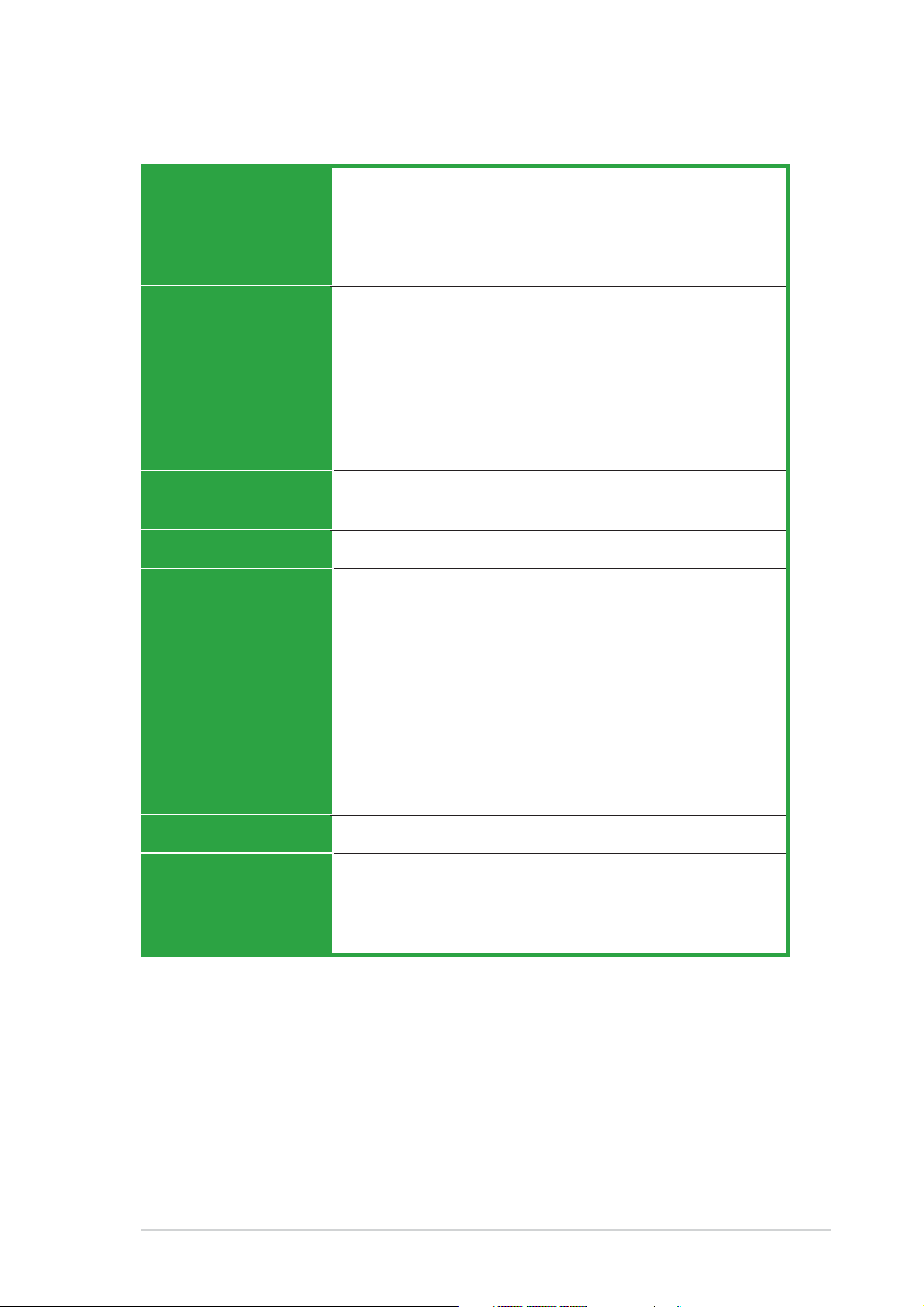
P5VD2-MX/P5V-VM DH specifications
summary
(continued on the next page)
CPUCPU
CPUCPU
CPU
ChipsetChipset
ChipsetChipset
Chipset
Front Side BusFront Side Bus
Front Side BusFront Side Bus
Front Side Bus
MemoryMemory
MemoryMemory
Memory
Expansion slotsExpansion slots
Expansion slotsExpansion slots
Expansion slots
VGAVGA
VGAVGA
VGA
StorageStorage
StorageStorage
Storage
AudioAudio
AudioAudio
Audio
LANLAN
LANLAN
LAN
USBUSB
USBUSB
USB
Special featuresSpecial features
Special featuresSpecial features
Special features
LGA775 socket for Intel
®
Core™2 Duo/Pentium
®
D/
Pentium
®
4/Celeron
®
CPU support
Intel
®
Presler 65nm Dual core CPU support
Intel
®
next generation Core™2 Duo CPU support
Compatible with Intel
®
05B/05A and 04B/04A
processors
Supports Intel EIST/EM64T/Hyper-Threading Technology
Northbridge: VIA P4M890
Southbridge: VIA VT8237A
1066/800/533 MHz
2 x 240-pin DIMM sockets support up to 4 GB of
DDR2 533/400 unbufferred non-ECC memory
1 x PCI Express x16
1 x PCI Express x1
2 x PCI slots
(Note: PCI-E x1 and JMicron JMB363 SATA controller
cannot be used simultaneously)
Integrated Graphics, up to 64MB shared memory
Support max. resolution to 2048 x 1536 (@75Hz)
Support max. refresh rate to 100Hz (@1600 x 1200)
VIA 8237A Southbridge supports:
— 2 x Ultra DMA 133/100/66/33
— 2 x Serial ATA (1.5 Gb/s) with RAID 0, RAID 1, and
JBOD configuration
JMicron JMB363 SATA controller supports:
— 1 x Internal Serial ATA 3 Gb/s
— 1 x External Serial ATA 3 Gb/s (SATA On-the-Go)
— RAID 0, RAID 1, and JBOD configuration
• High definition audio, ADI
®
AD1986A SoundMax 5.1
channel CODEC
• Supports Jack-sensing function
Realtek
®
RTL8201CL 10/100 Mbps LAN Controller
Supports up to 8 USB 2.0 ports
ASUS Q-Fan
ASUS EZ Flash
ASUS CrashFree BIOS 2
MyLogo™
xixi
xixi
xi
P5VD2-MX/P5V-VM DH specifications
summary
ASUS C.P.R. (CPU Parameter Recall)
SFS (Stepless Frequency Selection) from 133MHz up to
300MHz at 1MHz increment
Adjustable FSB/DDR ratio.
Fixed PCI-E/SATA frequencies.
1 x Parallel port
1 x External SATA
1 x LAN (RJ-45) port
4 x USB 2.0/1.1 ports
1 x VGA port
1 x PS/2 keyboard port
1 x PS/2 mouse port
6-Channel Audio I/O ports
4 Mb Flash ROM, Award BIOS, PnP, WfM2.0, ACPI2.0a,
SM BIOS 2.3
WOL by PME, WOR by PME, Chassis Intrusion, PXE, RPL
2 x USB 2.0 connectors for 4 additional USB 2.0 ports
1 x CPU fan connector
1 x Chassis fan connector
1 x COM connector
1 x 24-pin ATX power connector
1 x 4-pin ATX 12 V power connector
1 x CD/AUX audio-in connector
1 x Front panel audio connector
1 x S/PDIF out connector
Chassis intrusion
System panel connector
ATX from factor: 9.6 in x 8.6 in (23.5 cm x 21.8 cm)
Device drivers
ASUS PC Probe
ASUS Live Update utility
Anti-virus software (OEM version)
(continued on the next page)
OverclockingOverclocking
OverclockingOverclocking
Overclocking
FeaturesFeatures
FeaturesFeatures
Features
Rear panelRear panel
Rear panelRear panel
Rear panel
BIOS featuresBIOS features
BIOS featuresBIOS features
BIOS features
ManageabilityManageability
ManageabilityManageability
Manageability
InternalInternal
InternalInternal
Internal
connectorsconnectors
connectorsconnectors
connectors
Form FactorForm Factor
Form FactorForm Factor
Form Factor
Support CDSupport CD
Support CDSupport CD
Support CD
contentscontents
contentscontents
contents

xiixii
xiixii
xii
Extra specifications on P5V-VM DH
*Specifications are subject to change without notice.
*P5V-VM DH only supports max. 7 USB2.0 ports.
ASUS DigitalASUS Digital
ASUS DigitalASUS Digital
ASUS Digital
Home FeaturesHome Features
Home FeaturesHome Features
Home Features
ASUS DigitalASUS Digital
ASUS DigitalASUS Digital
ASUS Digital
HomeHome
HomeHome
Home
AccessoriesAccessories
AccessoriesAccessories
Accessories
Wirelss LANWirelss LAN
Wirelss LANWirelss LAN
Wirelss LAN
Rear PanelRear Panel
Rear PanelRear Panel
Rear Panel
InternalInternal
InternalInternal
Internal
ConnectorsConnectors
ConnectorsConnectors
Connectors
Support CDSupport CD
Support CDSupport CD
Support CD
ASUS WiFi-AP Solo
— 54 Mbps IEEE 802.11g and backwards compatible with
11 Mbps IEEE 802.11b
— Access point mode
— Station mode: Infrastructure mode or Ad-Hoc mode
ASUS DH Remote™
— Power
— Quick Power
— Noise Off
— EZ WiFi
— Full Screen
— AP Launch
— Media Controller Zone
ASUS MP3-In™
ASUS DH Remote
ASUS DH Remote Receiver
ASUS WiFi-AP Solo omni-directional antenna
ASUS MP3-In Module
54Mbps IEEE 802.11g (ASUS WiFi-AP Solo)
1 x WiFi-AP Solo antenna jack
1 x MP3-In connector
ASUS WiFi-AP Solo, ASUS DH Remote™ Application

ASUS P5VD2-MX/P5V-VM DHASUS P5VD2-MX/P5V-VM DH
ASUS P5VD2-MX/P5V-VM DHASUS P5VD2-MX/P5V-VM DH
ASUS P5VD2-MX/P5V-VM DH
1-11-1
1-11-1
1-1
1
Product
introduction
This chapter describes the motherboard
features and the new technologies
it supports.
1-21-2
1-21-2
1-2
Chapter 1: Product introductionChapter 1: Product introduction
Chapter 1: Product introductionChapter 1: Product introduction
Chapter 1: Product introduction
1.1 Welcome!
Thank you for buying an ASUSThank you for buying an ASUS
Thank you for buying an ASUSThank you for buying an ASUS
Thank you for buying an ASUS
®®
®®
®
P5VD2-MX/P5V-VM DH P5VD2-MX/P5V-VM DH
P5VD2-MX/P5V-VM DH P5VD2-MX/P5V-VM DH
P5VD2-MX/P5V-VM DH
motherboard!motherboard!
motherboard!motherboard!
motherboard!
The motherboard delivers a host of new features and latest technologies,
making it another standout in the long line of ASUS quality motherboards!
Before you start installing the motherboard, and hardware devices on it,
check the items in your package with the list below.
1.2 Package contents
Check your motherboard package for the following items.
MotherboardMotherboard
MotherboardMotherboard
Motherboard ASUS P5VD2-MX/P5V-VM DH motherboard
CablesCables
CablesCables
Cables 1 x Serial ATA power cable
1 x Serial ATA signal cable
1 x Ultra DMA 133/100 cables
1 x Floppy disk drive cable
AccessoriesAccessories
AccessoriesAccessories
Accessories I/O shield
ASUS DH Remote (only for P5V-VM DH)
ASUS DH Remote Receiver (only for P5V-VM DH)
ASUS WiFi-AP Solo omni-directional antenna (only
for P5V-VM DH)
ASUS MP3-In Module (only for P5V-VM DH)
Application CDApplication CD
Application CDApplication CD
Application CD ASUS motherboard support CD
DocumentationDocumentation
DocumentationDocumentation
Documentation User guide
If any of the above items is damaged or missing, contact your retailer.
1.3 Special features
1.3.11.3.1
1.3.11.3.1
1.3.1
Product highlightsProduct highlights
Product highlightsProduct highlights
Product highlights
Latest processor technology Latest processor technology
Latest processor technology Latest processor technology
Latest processor technology
The motherboard comes with a 775-pin surface mount Land Grid Array
(LGA) socket designed for the Intel
®
processor in the 775-land package.
The motherboard supports the Intel
®
Pentium
®
D processor with 1066/
800/533 MHz Front Side Bus (FSB). The motherboard also supports the
Intel
®
Hyper-Threading Technology and is fully compatible with Intel
®
05B/
05A and 04B/04A processors. See page 1-10 for details.
ASUS P5VD2-MX/P5V-VM DHASUS P5VD2-MX/P5V-VM DH
ASUS P5VD2-MX/P5V-VM DHASUS P5VD2-MX/P5V-VM DH
ASUS P5VD2-MX/P5V-VM DH
1-31-3
1-31-3
1-3
IntelIntel
IntelIntel
Intel
®®
®®
®
65nm Dual-Core CPU support 65nm Dual-Core CPU support
65nm Dual-Core CPU support 65nm Dual-Core CPU support
65nm Dual-Core CPU support
This motherboard supports Intel
®
Pentium
®
D/Pentium
®
4/Celeron
®
dual-core processors built on the 65-nanometer (nm) process technology
with copper interconnect. Dual-core processors contain two physical
CPU cores with dedicated L2 caches to meet demands for more powerful
processing. Intel
®
’s 65nm process is the most advanced chip manufacturing
technology, delivering breakthrough performance, enhanced media
experience, and low power consumption. Intel
®
65nm dual-core processors
utilize the latest package technologies for a thinner, lighter design without
compromising performance. This motherboard also supports Intel
®
next
generation Core™2 Duo CPU. This motherboard supports the latest Intel
®
Core™2 processors in LGA775 package. With new Intel
®
Core™
microarchitecture technology and 1066/800 MHz FSB, Intel
®
Core™2
processor is one of the most powerful and enrgy-efficient CPUs in the
world.
PCI Express™ interface PCI Express™ interface
PCI Express™ interface PCI Express™ interface
PCI Express™ interface
The motherboard fully supports PCI Express, the latest I/O interconnect
technology that speeds up the PCI bus. PCI Express features point-to-point
serial interconnections between devices and allows higher clockspeeds by
carrying data in packets. This high speed interface is software compatible with
existing PCI specifications.
Serial ATA 3Gb/s technology Serial ATA 3Gb/s technology
Serial ATA 3Gb/s technology Serial ATA 3Gb/s technology
Serial ATA 3Gb/s technology
The motherboard built with JMicron JMB363 SATA controller supports the
next-generation hard drives based on the Serial ATA (SATA) 3Gb/s storage
specification, delivering enhanced scalability and doubling the bus bandwidth
for high-speed data retrieval and saves. The external SATA port located at
the back I/O provides smart setup and hot-plug functions. Easily backup
photos, videos and other entertainment contents on external devices. See
pages 1-27 and 1-30 for details.
Dual RAID solutionDual RAID solution
Dual RAID solutionDual RAID solution
Dual RAID solution
The onboard VIA VT8237A chipset allows RAID 0, RAID 1, and JBOD
configuration for two SATA connectors, and JMicron JMB363 SATA
controller also supports RAID 0, RAID 1, and JBOD.
1-41-4
1-41-4
1-4
Chapter 1: Product introductionChapter 1: Product introduction
Chapter 1: Product introductionChapter 1: Product introduction
Chapter 1: Product introduction
S/PDIF digital sound ready S/PDIF digital sound ready
S/PDIF digital sound ready S/PDIF digital sound ready
S/PDIF digital sound ready
The motherboard supports the S/PDIF Out function through the S/PDIF
interface at midboard. The S/PDIF technology turns your computer into a
high-end entertainment system with digital connectivity to powerful audio and
speaker systems. See page 1-31 for details.
6-channel high definition audio 6-channel high definition audio
6-channel high definition audio 6-channel high definition audio
6-channel high definition audio
Onboard is the ADI AD1986A High Definition Audio 6-channel audio CODEC.
This CODEC is fully-compliant with Intel
®
High Definition Audio standard
(192 KHz, 24-bit audio). With the CODEC, 6-channel audio ports, and S/
PDIF interfaces, you can connect your computer to home theater decoders
to produce crystal-clear digital audio.
10/100 Mbps LAN Supports 10/100 Mbps LAN Supports
10/100 Mbps LAN Supports 10/100 Mbps LAN Supports
10/100 Mbps LAN Supports
The motherboard supports the Realtek
®
RTL8201CL 10/100 Mbps LAN
controller, providing easy connectivity to your network or broadband
connection with the onboard LAN port.
1.3.21.3.2
1.3.21.3.2
1.3.2
Innovative ASUS featuresInnovative ASUS features
Innovative ASUS featuresInnovative ASUS features
Innovative ASUS features
CrashFree BIOS 2 CrashFree BIOS 2
CrashFree BIOS 2 CrashFree BIOS 2
CrashFree BIOS 2
This feature allows you to restore the original BIOS data from the support CD
in case when the BIOS codes and data are corrupted. This protection
eliminates the need to buy a replacement ROM chip. See details on page 2-9.
USB 2.0 technology USB 2.0 technology
USB 2.0 technology USB 2.0 technology
USB 2.0 technology
The motherboard implements the Universal Serial Bus (USB) 2.0
specification, dramatically increasing the connection speed from the
12 Mbps bandwidth on USB 1.1 to a fast 480 Mbps on USB 2.0. USB 2.0 is
backward compatible with USB 1.1. See pages 1-25 and 1-33 for details.

ASUS P5VD2-MX/P5V-VM DHASUS P5VD2-MX/P5V-VM DH
ASUS P5VD2-MX/P5V-VM DHASUS P5VD2-MX/P5V-VM DH
ASUS P5VD2-MX/P5V-VM DH
1-51-5
1-51-5
1-5
ASUS Q-Fan technology ASUS Q-Fan technology
ASUS Q-Fan technology ASUS Q-Fan technology
ASUS Q-Fan technology
The ASUS Q-Fan technology smartly adjusts the CPU fan speed according
to the system loading to ensure quiet, cool, and efficient operation.
ASUS EZ Flash BIOS ASUS EZ Flash BIOS
ASUS EZ Flash BIOS ASUS EZ Flash BIOS
ASUS EZ Flash BIOS
With the ASUS EZ Flash, you can easily update the system BIOS even
before loading the operating system. No need to use a DOS-based utility or
boot from a floppy disk. See page 2-6 for details.
C.P.R. (CPU Parameter Recall) C.P.R. (CPU Parameter Recall)
C.P.R. (CPU Parameter Recall) C.P.R. (CPU Parameter Recall)
C.P.R. (CPU Parameter Recall)
The C.P.R. feature of the motherboard BIOS allows automatic re-setting to
the BIOS default settings in case the system hangs due to overclocking.
When the system hangs due to overclocking, C.P.R. eliminates the need to
open the system chassis and clear the RTC data. Simply shut down and
reboot the system, and the BIOS automatically restores the CPU default
setting for each parameter.
1.3.31.3.3
1.3.31.3.3
1.3.3
ASUS Digital Home for P5V-VM DH specialASUS Digital Home for P5V-VM DH special
ASUS Digital Home for P5V-VM DH specialASUS Digital Home for P5V-VM DH special
ASUS Digital Home for P5V-VM DH special
featuresfeatures
featuresfeatures
features
ASUS WiFi-AP Solo ASUS WiFi-AP Solo
ASUS WiFi-AP Solo ASUS WiFi-AP Solo
ASUS WiFi-AP Solo
(Only for P5V-VM DH) (Only for P5V-VM DH)
(Only for P5V-VM DH) (Only for P5V-VM DH)
(Only for P5V-VM DH)
The ASUS WiFi-AP Solo allows a new level of versitility for your PC, enabling
it to create a complete wireless home network in either AP or wirelesss
client mode. Users will be able to play LAN games, connecting to the
Internet, access and share printers, and use Skype from anywhere within
range. The ASUS WiFi-AP Solo can provide these functions even when the
PC is in sleep mode, so users can use Skype as a true replacement for
tradition long distance telephone service. WiFi-AP Solo is an on-board
feature, which means that users will save the extra WiFi-AP cost.

1-61-6
1-61-6
1-6
Chapter 1: Product introductionChapter 1: Product introduction
Chapter 1: Product introductionChapter 1: Product introduction
Chapter 1: Product introduction
ASUS DH Remote™ ASUS DH Remote™
ASUS DH Remote™ ASUS DH Remote™
ASUS DH Remote™
(Only for P5V-VM DH) (Only for P5V-VM DH)
(Only for P5V-VM DH) (Only for P5V-VM DH)
(Only for P5V-VM DH)
The ASUS DH Remote™ is a convenient PC remote controller that gives
users unprecedented control over their PCs from the comfort of their
couches. With the touch of a button, users can instantly operate the
following functions:
PowerPower
PowerPower
Power: Turns the computer on/off.
Quick PowerQuick Power
Quick PowerQuick Power
Quick Power: Puts the computer quickly into sleep mode.
Noise OffNoise Off
Noise OffNoise Off
Noise Off: Reduces the noise coming from the computer.
EZ WiFiEZ WiFi
EZ WiFiEZ WiFi
E Z W i F i: Puts the computer quickly into sleep mode but allowing
WiFi-AP Solo™ to still operate.
Full ScreenFull Screen
Full ScreenFull Screen
Full Screen: Puts the media application into full screen.
AP LaunchAP Launch
AP LaunchAP Launch
AP Launch: Launches the media application.
Media Control ZoneMedia Control Zone
Media Control ZoneMedia Control Zone
Media Control Zone: Controls the media application.
ASUS MP3-In™ ASUS MP3-In™
ASUS MP3-In™ ASUS MP3-In™
ASUS MP3-In™
(Only for P5V-VM DH) (Only for P5V-VM DH)
(Only for P5V-VM DH) (Only for P5V-VM DH)
(Only for P5V-VM DH)
A convenient interface between computers and MP3 players, the ASUS
MP3-In™ feature enables MP3 players to connect to PC speakers even when
the PC power is off, which means that users can enjoy the sound quality
from PC speakers without additional stereo equipment cost. Please refer
page 1-35 and ASUS MP3-In™ quick installation guide for details.
ASUS P5VD2-MX/P5V-VM DHASUS P5VD2-MX/P5V-VM DH
ASUS P5VD2-MX/P5V-VM DHASUS P5VD2-MX/P5V-VM DH
ASUS P5VD2-MX/P5V-VM DH
1-71-7
1-71-7
1-7
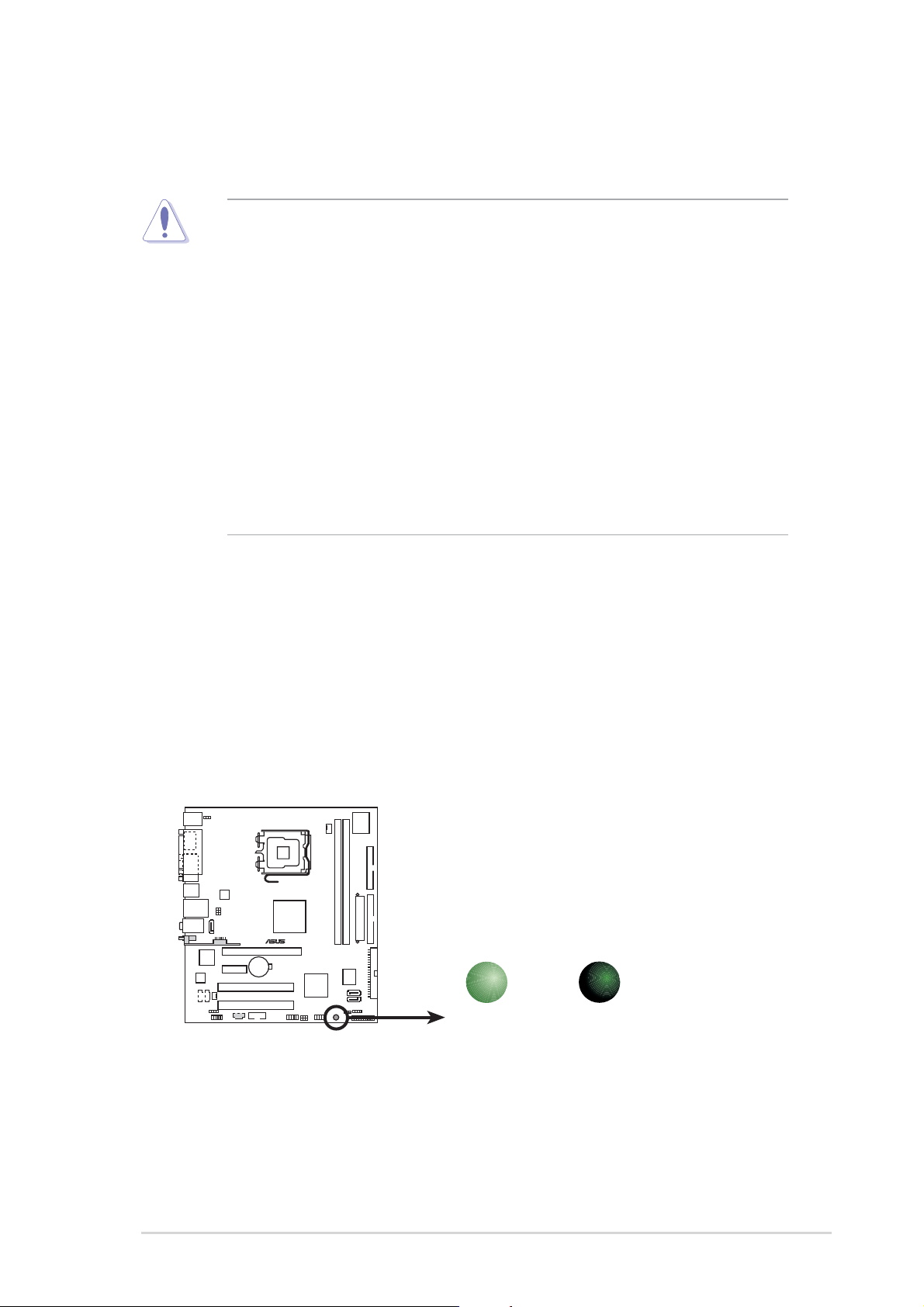
Onboard LEDOnboard LED
Onboard LEDOnboard LED
Onboard LED
The motherboard comes with a standby power LED that lights up to
indicate that the system is ON, in sleep mode, or in soft-off mode.
This is a reminder that you should shut down the system and unplug
the power cable before removing or plugging in any motherboard
component. The illustration below shows the location of the onboard
LED.
1.4 Before you proceed
Take note of the following precautions before you install motherboard
components or change any motherboard settings.
• Unplug the power cord from the wall socket before touching any
component.
• Use a grounded wrist strap or touch a safely grounded object or to
a metal object, such as the power supply case, before handling
components to avoid damaging them due to static electricity
• Hold components by the edges to avoid touching the ICs on them.
• Whenever you uninstall any component, place it on a grounded
antistatic pad or in the bag that came with the component.
•
Before you install or remove any component, ensureBefore you install or remove any component, ensure
Before you install or remove any component, ensureBefore you install or remove any component, ensure
Before you install or remove any component, ensure
that the ATX power supply is switched off or thethat the ATX power supply is switched off or the
that the ATX power supply is switched off or thethat the ATX power supply is switched off or the
that the ATX power supply is switched off or the
power cord is detached from the power supply. power cord is detached from the power supply.
power cord is detached from the power supply. power cord is detached from the power supply.
power cord is detached from the power supply. Failure
to do so may cause severe damage to the motherboard, peripherals,
and/or components.
®
Onboard LED
SB_PWR
ON
Standby
Power
OFF
Powered
Off
1-81-8
1-81-8
1-8
Chapter 1: Product introductionChapter 1: Product introduction
Chapter 1: Product introductionChapter 1: Product introduction
Chapter 1: Product introduction
1.5 Motherboard overview
Before you install the motherboard, study the configuration of your chassis
to ensure that the motherboard fits into it.
Make sure to unplug the power cord before installing or removing the
motherboard. Failure to do so can cause you physical injury and damage
motherboard components.
Do not overtighten the screws! Doing so can damage the motherboard.
1.5.11.5.1
1.5.11.5.1
1.5.1
Placement directionPlacement direction
Placement directionPlacement direction
Placement direction
When installing the motherboard, make sure that you place it into the
chassis in the correct orientation. The edge with external ports goes to the
rear part of the chassis as indicated in the image below.
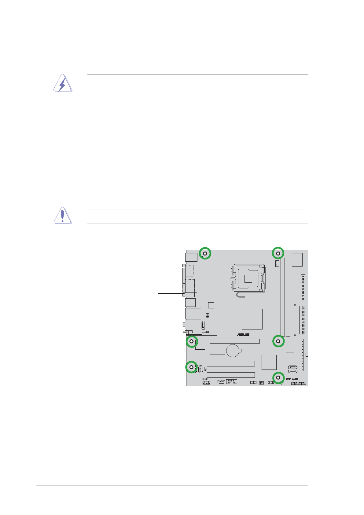
1.5.21.5.2
1.5.21.5.2
1.5.2
Screw holesScrew holes
Screw holesScrew holes
Screw holes
Place six (6) screws into the holes indicated by circles to secure the
motherboard to the chassis.
Place this side towardsPlace this side towards
Place this side towardsPlace this side towards
Place this side towards
the rear of the chassisthe rear of the chassis
the rear of the chassisthe rear of the chassis
the rear of the chassis
®
ASUS P5VD2-MX/P5V-VM DHASUS P5VD2-MX/P5V-VM DH
ASUS P5VD2-MX/P5V-VM DHASUS P5VD2-MX/P5V-VM DH
ASUS P5VD2-MX/P5V-VM DH
1-91-9
1-91-9
1-9
1.5.31.5.3
1.5.31.5.3
1.5.3
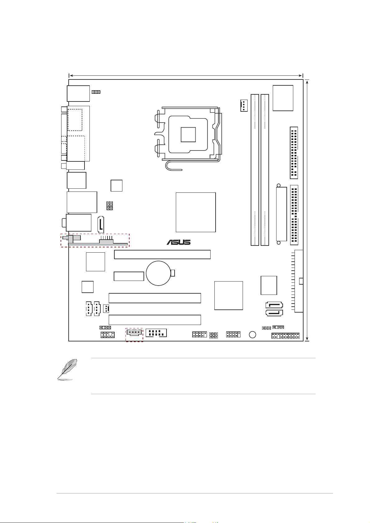
P5VD2-MX/P5V-VM DH Motherboard layoutP5VD2-MX/P5V-VM DH Motherboard layout
P5VD2-MX/P5V-VM DH Motherboard layoutP5VD2-MX/P5V-VM DH Motherboard layout
P5VD2-MX/P5V-VM DH Motherboard layout
• The USB9 port, WIFI connecotr, and MP3IN connector are only for
P5V-VM DH.
• USB1 and USB2 ports are only for P5VD2-MX.
21.8cm (8.6in)
PCI1
4Mb
BIOS
JMicron
JMB363
USBPW56
USBPW78
CHA_FAN
USB56
24.5cm (9.6in)
PCI2
PANEL
ATX12V
CPU_FAN
Super
I/O
AAFP
DDR2 DIMM2 (64 bit,240-pin module)
EATXPWR
SATA 2
FLOPPY
CR2032 3V
Lithium Cell
CMOS Power
VIA
VT8237A
VIA
P4M890
PCIE1
PS/2KBMS
T: Mouse
B: Keyboard
Below:Mic In
Center:Line Out
Top:Line In
USB12
LAN_USB34
PARALLEL PORT
VGA
DDR2 DIMM1 (64 bit,240-pin module)
SATA 1
PRI_IDE
USB78
USBPW34
USBPW12
KBPWR
AUXCD
CLRTC
SB_PWR
SPDIF_OUT
CHASSIS
RTL8201CL
®
LGA775
COM2
ES ATA
SEC_IDE
SATA_A
PCIEX16
WIFI
USB9
MP3IN
1-101-10
1-101-10
1-10
Chapter 1: Product introductionChapter 1: Product introduction
Chapter 1: Product introductionChapter 1: Product introduction
Chapter 1: Product introduction
1.6.11.6.1
1.6.11.6.1
1.6.1
Installling the CPUInstallling the CPU
Installling the CPUInstallling the CPU
Installling the CPU
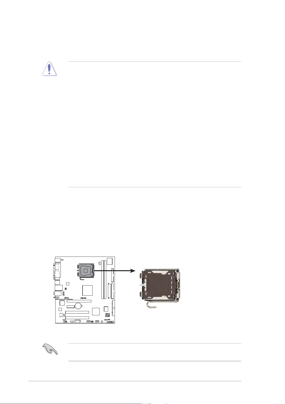
To install a CPU:
1. Locate the CPU socket on the motherboard.
1.6 Central Processing Unit (CPU)
The motherboard comes with a surface mount LGA775 socket designed for
the Intel
®
Core™2 Duo/Pentium
®
D/ Pentium
®
4/Celeron
®
processor in the
775-land package.
•
Your boxed Intel
®
Core™2 Duo/Pentium
®
D/Pentium
®
4/Celeron
®
LGA775 processor package should come with installation
instructions for the CPU, fan and heatsink assembly. If the
instructions in this section do not match the CPU documentation,
follow the latter.
• Upon purchase of the motherboard, make sure that the PnP cap is
on the socket and the socket pins are not bent. Contact your
retailer immediately if the PnP cap is missing, or if you see any
damage to the PnP cap/socket pins/motherboard components.
ASUS will shoulder the cost of repair only if the damage is shipment/
transit-related.
• Keep the cap after installing the motherboard. ASUS will process
Return Merchandise Authorization (RMA) requests only if the
motherboard comes with the cap on the LGA775 socket.
•
The product warranty does not cover damage to the socket pins
resulting from incorrect CPU installation/removal, or misplacement/
loss/incorrect removal of the PnP cap.
Before installing the CPU, make sure that the socket box is facing
towards you and the load lever is on your left.
®
CPU Socket 775
ASUS P5VD2-MX/P5V-VM DHASUS P5VD2-MX/P5V-VM DH
ASUS P5VD2-MX/P5V-VM DHASUS P5VD2-MX/P5V-VM DH
ASUS P5VD2-MX/P5V-VM DH
1-111-11
1-111-11
1-11
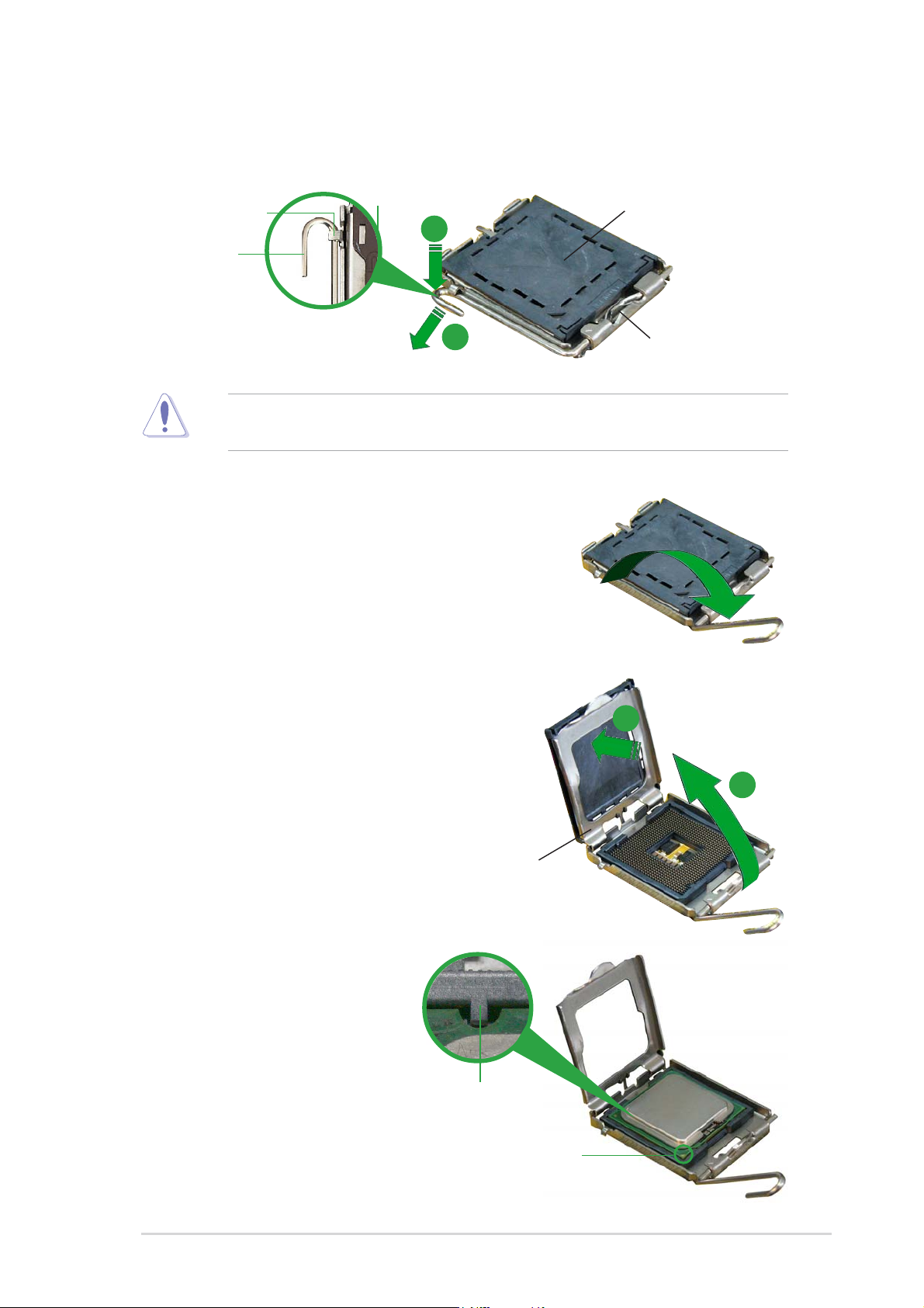
3. Lift the load lever in the direction
of the arrow to a 135º angle.
4. Lift the load plate with your
thumb and forefinger to a 100º
angle (A), then push the PnP cap
from the load plate window to
remove (B).
To prevent damage to the socket pins, do not remove the PnP cap
unless you are installing a CPU.
5. Position the CPU over the
socket, making sure that
the gold triangle is on
the bottom-left corner of
the socket. The socket
alignment key should fit
into the CPU notch.
2. Press the load lever with your thumb (A) and move it to the left (B)
until it is released from the retention tab.
Retention tabRetention tab
Retention tabRetention tab
Retention tab
Load leverLoad lever
Load leverLoad lever
Load lever
This side of the camThis side of the cam
This side of the camThis side of the cam
This side of the cam
box should face you.box should face you.
box should face you.box should face you.
box should face you.
PnP CapPnP Cap
PnP CapPnP Cap
PnP Cap
A
B
Load plateLoad plate
Load plateLoad plate
Load plate
A
B
Alignment keyAlignment key
Alignment keyAlignment key
Alignment key
Gold triangle markGold triangle mark
Gold triangle markGold triangle mark
Gold triangle mark
1-121-12
1-121-12
1-12
Chapter 1: Product introductionChapter 1: Product introduction
Chapter 1: Product introductionChapter 1: Product introduction
Chapter 1: Product introduction
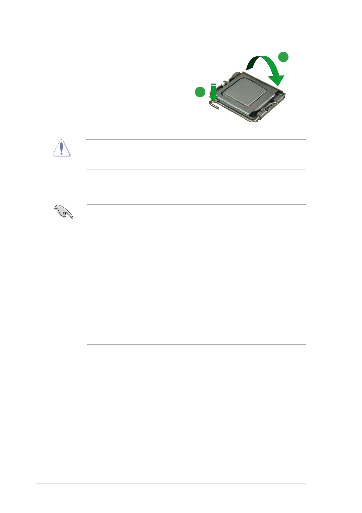
The CPU fits in only one correct orientation. DO NOT force the CPU into
the socket to prevent bending the connectors on the socket and
damaging the CPU!
6. Close the load plate (A), then
push the load lever (B) until it
snaps into the retention tab.
Notes on IntelNotes on Intel
Notes on IntelNotes on Intel
Notes on Intel
®
Hyper-Threading Technology Hyper-Threading Technology
Hyper-Threading Technology Hyper-Threading Technology
Hyper-Threading Technology
• This motherboard supports Intel
®
Pentium
®
4 CPUs in the 775-land
package with Hyper-Threading Technology.
• Hyper-Threading Technology is supported under Windows
®
XP/2003
Server and Linux 1.7.x (kernel) and later versions only. Under Linux,
use the Hyper-Threading compiler to compile the code. If you are
using any other operating systems, disable the Hyper-Threading
Technology item in the BIOS to ensure system stability and
performance.
• Installing Windows
®
XP Service Pack 1 or later version is
recommended.
• Make sure to enable the Hyper-Threading Technology item in BIOS
before installing a supported operating system.
• For more information on Hyper-Threading Technology, visit
www.intel.com/info/hyperthreading.
To use the Hyper-Threading Technology on this motherboard:
1. Install an Intel
®
Pentium
®
4 CPU in the 775-land package that supports
Hyper-Threading Technology.
2. Power up the system and enter the BIOS Setup (see Chapter 2: BIOS
setup). Under the Advanced Menu, make sure that the item
Hyper-Threading Technology is set to Enabled. The item appears only
if you installed a CPU that supports Hyper-Threading Technology.
3. Reboot the computer.
A
B
ASUS P5VD2-MX/P5V-VM DHASUS P5VD2-MX/P5V-VM DH
ASUS P5VD2-MX/P5V-VM DHASUS P5VD2-MX/P5V-VM DH
ASUS P5VD2-MX/P5V-VM DH
1-131-13
1-131-13
1-13
1.6.21.6.2
1.6.21.6.2
1.6.2
Installling the CPU heatsink and fanInstallling the CPU heatsink and fan
Installling the CPU heatsink and fanInstallling the CPU heatsink and fan
Installling the CPU heatsink and fan
The Intel
®
Pentium
®
4 LGA775 processor requires a specially designed
heatsink and fan assembly to ensure optimum thermal condition and
performance.
• Install the motherboard to the chassis before you install the CPU fan
and heatsink assembly
• When you buy a boxed Intel
®
Pentium
®
4 processor, the package
includes the CPU fan and heatsink assembly. If you buy a CPU
separately, make sure that you use only Intel
®
-certified
multi-directional heatsink and fan.
• Your Intel
®
Pentium
®
4 heatsink and fan assembly comes in a push-
pin design and requires no tool to install.
If you purchased a separate CPU heatsink and fan assembly, make sure
that a Thermal Interface Material is properly applied to the CPU heatsink
or CPU before you install the heatsink and fan assembly.
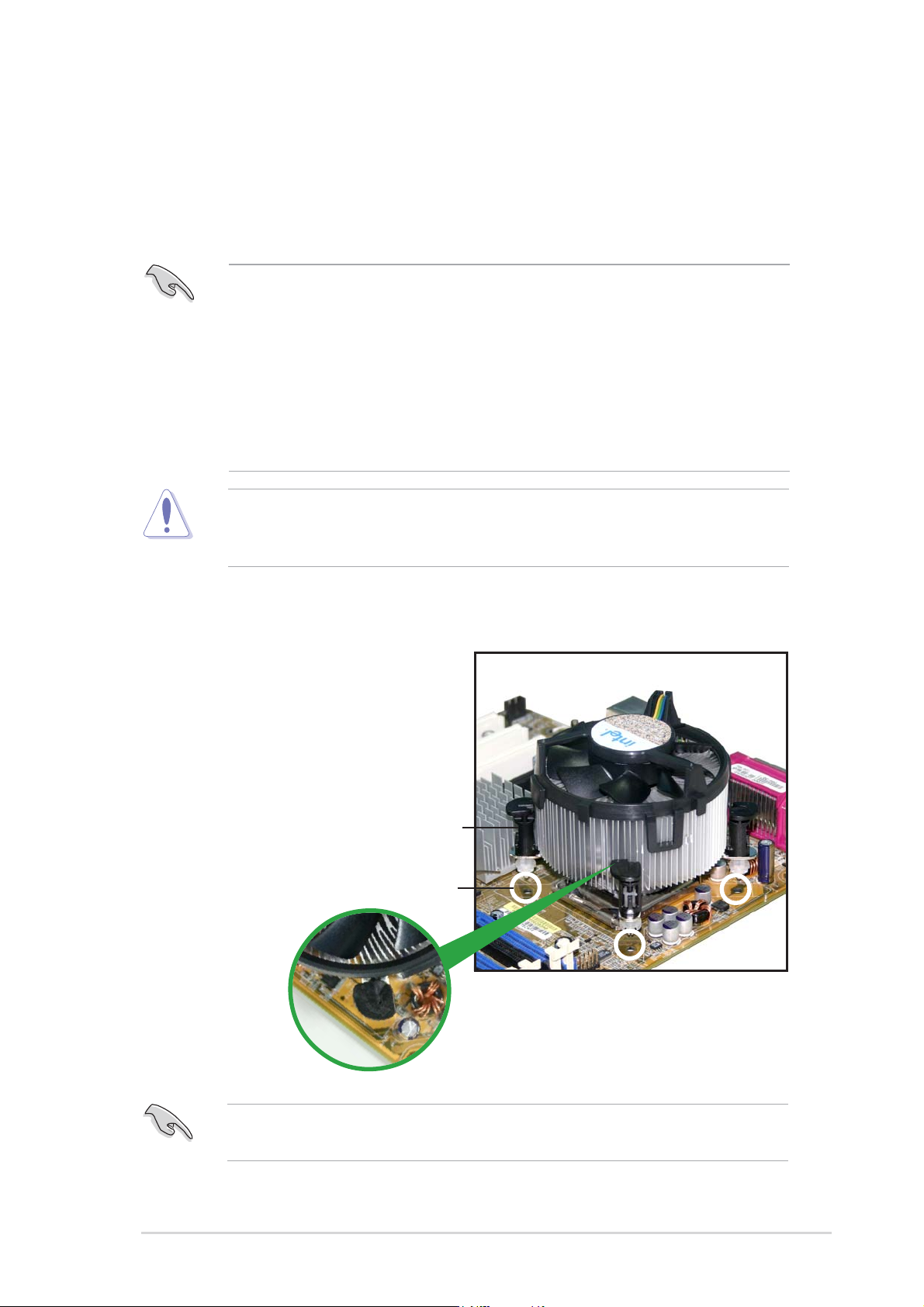
To install the CPU heatsink and fan:
1. Place the heatsink on top of the
installed CPU, making sure that
the four fasteners match the
holes on the motherboard.
FastenerFastener
FastenerFastener
Fastener
Motherboard holeMotherboard hole
Motherboard holeMotherboard hole
Motherboard hole
Make sure each fastener is oriented as shown, with the narrow groove
directed outward.
1-141-14
1-141-14
1-14
Chapter 1: Product introductionChapter 1: Product introduction
Chapter 1: Product introductionChapter 1: Product introduction
Chapter 1: Product introduction
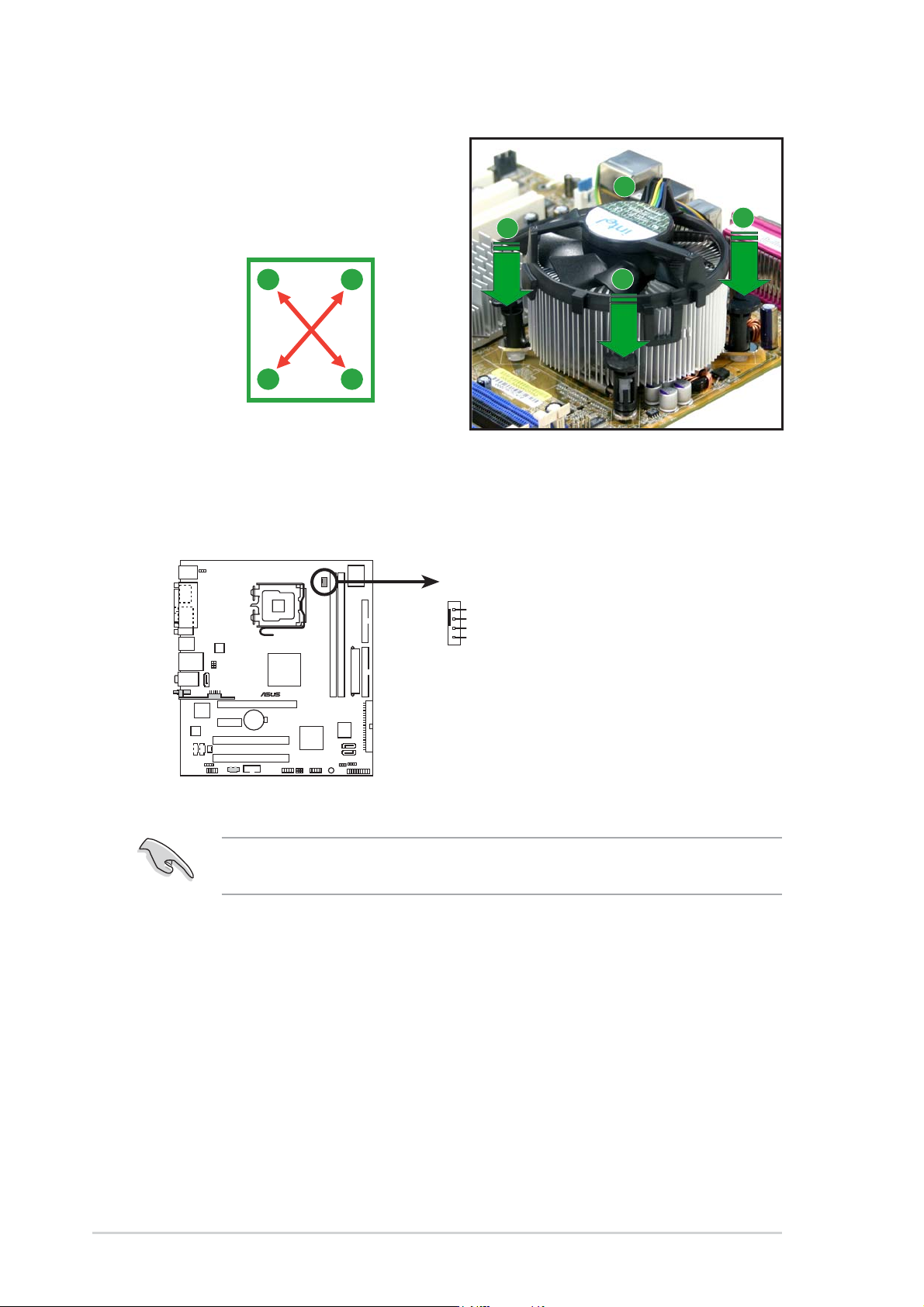
Do not forget to connect the CPU fan connector! Hardware monitoring
errors can occur if you fail to plug this connector.
3. When the fan and heatsink assembly is in place, connect the CPU fan
cable to the connector on the motherboard labeled CPU_FAN.
2. Push down two fasteners at a
time in a diagonal sequence to
secure the heatsink and fan
assembly in place.
A
A
B
B
B
B
A
A
®
CPU fan connector
CPU_FAN
GND
CPU FAN PWR
CPU FAN IN
CPU FAN PWM
ASUS P5VD2-MX/P5V-VM DHASUS P5VD2-MX/P5V-VM DH
ASUS P5VD2-MX/P5V-VM DHASUS P5VD2-MX/P5V-VM DH
ASUS P5VD2-MX/P5V-VM DH
1-151-15
1-151-15
1-15
1.6.31.6.3
1.6.31.6.3
1.6.3
Uninstalling the CPU heatsink and fanUninstalling the CPU heatsink and fan
Uninstalling the CPU heatsink and fanUninstalling the CPU heatsink and fan
Uninstalling the CPU heatsink and fan
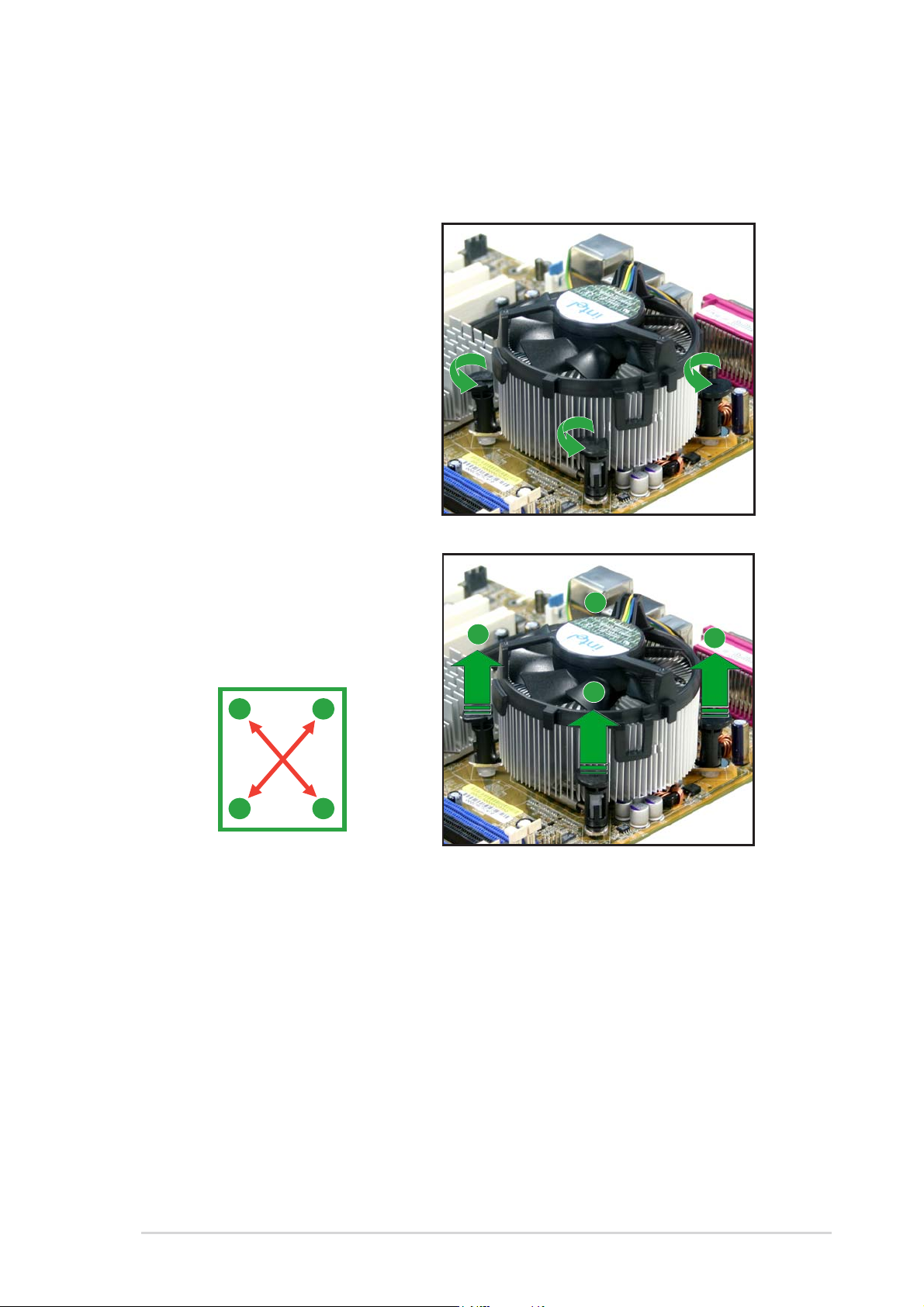
To uninstall the CPU heatsink and fan:
1. Disconnect the CPU fan
cable from the connector
on the motherboard labeled
CPU_FAN.
2. Rotate each fastener
counterclockwise.
3. Pull up two fasteners at a
time in a diagonal sequence
to disengage the heatsink
and fan assembly from the
motherboard.
A
A
B
B
B
B
A
A
1-161-16
1-161-16
1-16
Chapter 1: Product introductionChapter 1: Product introduction
Chapter 1: Product introductionChapter 1: Product introduction
Chapter 1: Product introduction
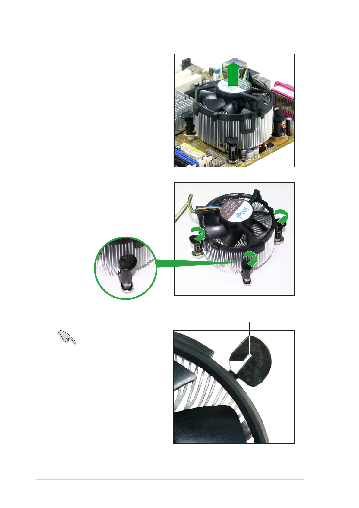
4. Remove the heatsink and fan
assembly from the
motherboard.
5. Rotate each fastener
clockwise to reset the
orientation.
The narrow end of the
groove should point
outward after resetting.
(The photo shows the
groove shaded for
emphasis.)
Narrow end of the grooveNarrow end of the groove
Narrow end of the grooveNarrow end of the groove
Narrow end of the groove
ASUS P5VD2-MX/P5V-VM DHASUS P5VD2-MX/P5V-VM DH
ASUS P5VD2-MX/P5V-VM DHASUS P5VD2-MX/P5V-VM DH
ASUS P5VD2-MX/P5V-VM DH
1-171-17
1-171-17
1-17
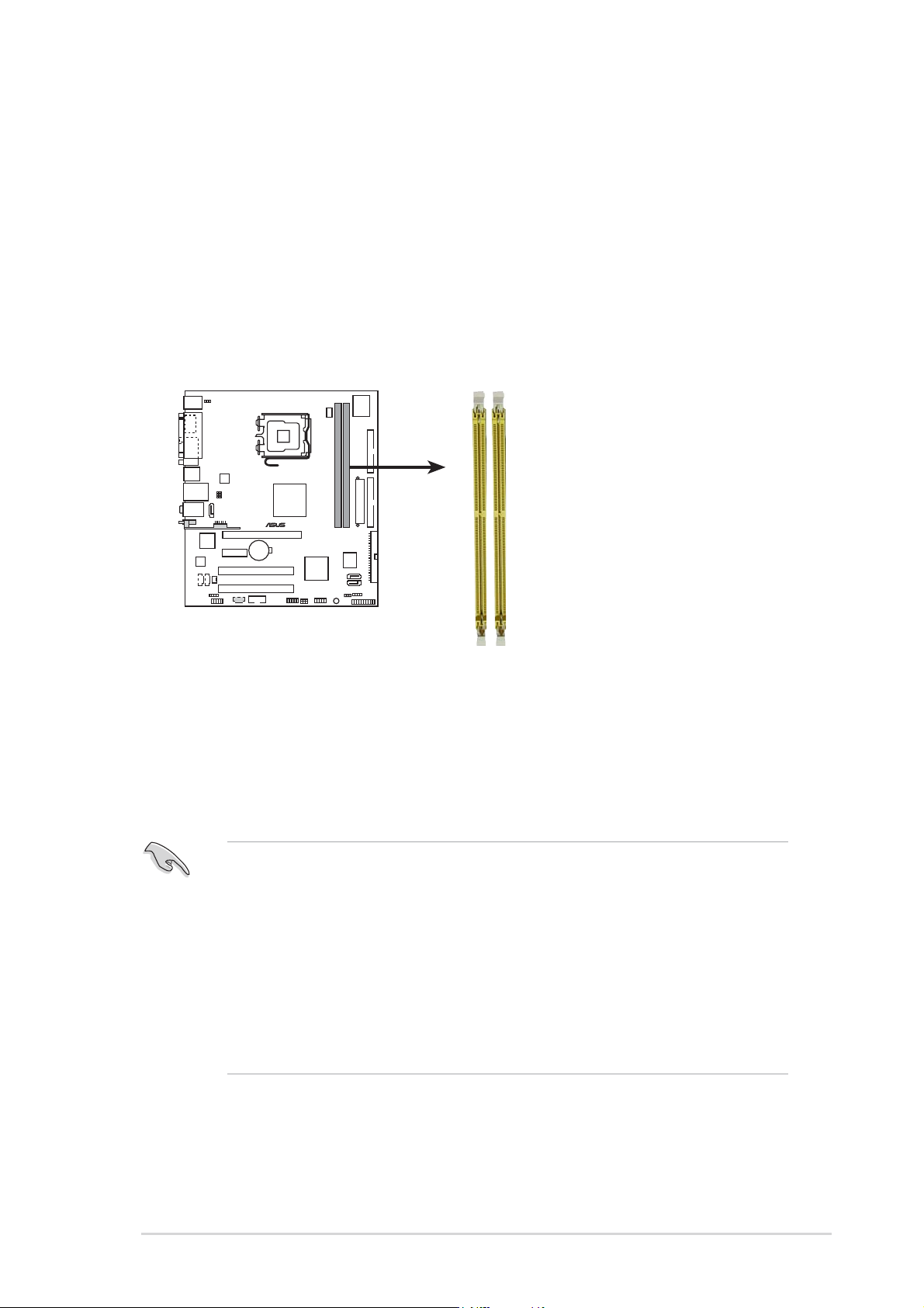
1.7 System memory
1.7.11.7.1
1.7.11.7.1
1.7.1
OverviewOverview
OverviewOverview
Overview
The motherboard comes with two Double Data Rate 2 (DDR2) Dual Inline
Memory Modules (DIMM) sockets.
A DDR2 module has the same physical dimensions as a DDR DIMM but has a
240-pin footprint compared to the 184-pin DDR DIMM. DDR2 DIMMs are
notched differently to prevent installation on a DDR DIMM socket.
The figure illustrates the location of the DDR2 DIMM sockets:
1.7.21.7.2
1.7.21.7.2
1.7.2
Memory configurationsMemory configurations
Memory configurationsMemory configurations
Memory configurations
You may install 256 MB, 512 MB, 1 GB, and 2 GB unbuffered non-ECC DDR2
DIMMs into the DIMM sockets.
• Always install DIMMs with the same CAS latency. For optimum
compatibility, it is recommended that you obtain memory modules
from the same vendor. Refer to the DDR2 Qualified Vendors List on
the next page for details.
• Due to chipset resource allocation, the system may detect less than
4 GB system memory when you installed two 2 GB DDR2 memory
modules.
• This motherboard does not support memory modules made up of
128 Mb chips or double sided x16 memory modules.
®
240-pin DDR2 DIMM sockets
DIMM1
DIMM2
1-181-18
1-181-18
1-18
Chapter 1: Product introductionChapter 1: Product introduction
Chapter 1: Product introductionChapter 1: Product introduction
Chapter 1: Product introduction
DDR2 533 Qualified Vendors ListDDR2 533 Qualified Vendors List
DDR2 533 Qualified Vendors ListDDR2 533 Qualified Vendors List
DDR2 533 Qualified Vendors List
DIMM support
Size Size
Size Size
Size
VendorVendor
VendorVendor
Vendor
ModelModel
ModelModel
Model
BrandBrand
BrandBrand
Brand
Side(s)Side(s)
Side(s)Side(s)
Side(s)
ComponentComponent
ComponentComponent
Component
AA
AA
A
BB
BB
B
256MB KINGSTON E5116AB-5C-E N/A SS KVR533D2N4/256 V V
512MB KINGSTON HY5PS56821F-C4 N/A DS KVR533D2N4/512 V V
1024MB KINGSTON D6408TE7BL-37 N/A DS KVR533D2N4/1G V V
2048MB KINGSTON E1108AA-5C-E N/A DS KVR533D2N4/2G V V
512MB SAMSUNG K4T51083QB-GCD5 N/A SS M378T6553BG0-CD5 V V
256MB SAMSUNG K4T56083QF-GCD5 N/A SS M378T3253FG0-CD5 V V
512MB SAMSUNG K4T56083QF-GCD5 N/A DS M378T6453FG0-CD5 V V
256MB MICRON 4DBIIZ9BQT N/A SS N/A V V
512MB Infineon HYB18T512800AC37 N/A SS HYS64T64000GU-3.7-A V V
256MB Infineon HYB18T512160AF-3.7 N/A SS HYS64T32000HU-3.7-A V V
512MB Infineon HYB18T512800AF37 N/A SS HYS64T64000HU-3.7-A V V
1024MB Infineon HYB18T512800AF37 N/A DS HYS64T128020HU-3.7-A V V
2048MB Infineon HYB18T1G800AF-3.7 N/A DS HYS64T256020HU-3.7-A V V
256MB Infineon HYB18T5121608BF-3.7 N/A SS HYS64T32000HU-3.7-B V V
512MB Infineon HYB18T512800BF37 N/A SS HYS64T64000HU-3.7-B V V
1024MB Infineon HYB18T512800BF37 N/A DS HYS64T128020HU-3.7-B V V
512MB Hynix HY5PS12821F-C4 N/A SS HYMP564U648-C4 V V
1024MB Hynix HY5PS12821F-C4 N/A DS HYMP512U648-C4 V V
1024MB Hynix HY5PS12821FP-C4 N/A DS HYMP512U648-C4 V V
512MB Hynix HY5PS12821AFP-C3 N/A SS HYMP564U64AP8-C3 V V
1024MB Hynix HY5PS12821AFP-C3 N/A DS HYMP512U64AP8-C3 V V
512MB ELPIDA E5108AB-5C-E N/A SS EBE51UD8ABFA-5C V V
512MB ELPIDA E5108AB-5C-E N/A SS EBE51UD8ABFA-5C-E V V
1024MB ELPIDA E5108AB-5C-E N/A DS EBE11UD8ABFA-5C-E V V
2048MB ELPIDA E1108AA-5C-E N/A DS EBE21EE8AAFA-5C-E V V
256MB CORSAIR MIII0051832M8CEC N/A SS VS256MB533D2 V V
512MB CORSAIR MI110052432M8CEC N/A DS VS512MB533D2 V V
256MB Apacer E5116AB-5C-E N/A SS 78.81077.420 V V
256MB KINGMAX E5116AB-5C-E N/A SS KLBB68F-36EP4 V V
512MB KINGMAX E5108AE-5C-E N/A SS KLBC28F-A8EB4 V V
1024MB KINGMAX E5108AE-5C-E N/A DS KLBD48F-A8EB4 V V
512MB Transcend K4T51083QB-GCD5 N/A SS TS64MLQ64V5J V V
1024MB Transcend K4T51083QB-GCD5 N/A DS TS128MLQ64V5J V V
256MB CENTURY K4T56083QF-GCD5 N/A SS 25V6S8SSD5F4-K43 V V
512MB CENTURY E5108AB-5C-E N/A SS 25V2H8EL5CB4-J43 V V
1024MB CENTURY E5108AB-5C-E N/A DS 25V0H8EL5CB4-J45 V V
256MB elixir N2TU51216AF-37B N/A SS M2U25664TUH4A0F-37B V V
512MB elixir N2TU51280AF-37B N/A SS M2U51264TU88A0F-37B V V
256MB Aeneon AET960UD00-37C88X N/A SS AET560UD00-370A98X V V
512MB Aeneon AET960UD00-37C88X N/A SS AET660UD00-370A98X V V
256MB Aeneon AET94F370A N/A SS AET560UD00-370A98Z V V
256MB Aeneon AET94F370A N/A SS AET560UD00-370A98X V V
512MB Aeneon AET93F370A N/A SS AET660UD00-370A98Z V V
512MB Aeneon AET93F370A N/A SS AET660UD00-370A98X V V
512MB Aeneon AET93F370 N/A SS AET660UD00-370A98X V V
1024MB Aeneon AET93F370A N/A DS AET760UD00-370A98X V V
256MB NANYA NT5TU32M16AF-37B N/A SS NT256T64UH4A0F-37B V V
512MB NANYA NT5TU64M8AF-37B N/A SS NT512T64U88A0F-37B V V
1024MB NANYA NT5TU64M8AF-37B N/A DS NT1GT64U8HA0F-37B V V
1024MB PQI 64MX8D2-E N/A DS MEAB-323LA V V
512MB TwinMOS K4T51083QB-GCD5 N/A SS 8D-22JB5-K2T V V
256MB SimpleTech 858S032F25A N/A SS SVM-42DR2/256 V V
512MB SimpleTech 858S064F25A N/A DS SVM-42DR2/512 V V

ASUS P5VD2-MX/P5V-VM DHASUS P5VD2-MX/P5V-VM DH
ASUS P5VD2-MX/P5V-VM DHASUS P5VD2-MX/P5V-VM DH
ASUS P5VD2-MX/P5V-VM DH
1-191-19
1-191-19
1-19
Legend:Legend:
Legend:Legend:
Legend:
Side(s): SS Side(s): SS
Side(s): SS Side(s): SS
Side(s): SS — Single-sided
DS DS
DS DS
D S — Double-sided
DIMM support:DIMM support:
DIMM support:DIMM support:
DIMM support:
A A
A A
A — Supports one module inserted in any slot as Single-channel memory
configuration
BB
BB
B — Supports one pair of modules inserted into yellow slots as one pair of Single-
channel memory configuration
1.7.31.7.3
1.7.31.7.3
1.7.3
Installing a DIMMInstalling a DIMM
Installing a DIMMInstalling a DIMM
Installing a DIMM
1. Unlock a DIMM socket by
pressing the retaining clips
outward.
2. Align a DIMM on the socket such
that the notch on the DIMM
matches the break on the
socket.
3. Firmly insert the DIMM into the
socket until the retaining clips
snap back in place and the DIMM
is properly seated.
Make sure to unplug the power supply before adding or removing DIMMs
or other system components. Failure to do so may cause severe damage
to both the motherboard and the components.
Unlocked retaining clipUnlocked retaining clip
Unlocked retaining clipUnlocked retaining clip
Unlocked retaining clip
DDR2 DIMM notchDDR2 DIMM notch
DDR2 DIMM notchDDR2 DIMM notch
DDR2 DIMM notch
1.7.41.7.4
1.7.41.7.4
1.7.4
Removing a DIMMRemoving a DIMM
Removing a DIMMRemoving a DIMM
Removing a DIMM
To remove a DIMM:
1. Simultaneously press the
retaining clips outward to unlock
the DIMM.
2. Remove the DIMM from the socket.
Support the DIMM lightly with your fingers when pressing the retaining
clips. The DIMM might get damaged when it flips out with extra force.
DDR2 DIMM notchDDR2 DIMM notch
DDR2 DIMM notchDDR2 DIMM notch
DDR2 DIMM notch
1
• A DDR2 DIMM is keyed with a notch so that it fits in only one
direction. DO NOT force a DIMM into a socket to avoid damaging the
DIMM.
• The DDR2 DIMM sockets do not support DDR DIMMs. Do not install
DDR DIMMs to the DDR2 DIMM sockets.
3
2
1
1
2
1
1

1-201-20
1-201-20
1-20
Chapter 1: Product introductionChapter 1: Product introduction
Chapter 1: Product introductionChapter 1: Product introduction
Chapter 1: Product introduction
1.8 Expansion slots
In the future, you may need to install expansion cards. The following
sub-sections describe the slots and the expansion cards that they support.
1.8.11.8.1
1.8.11.8.1
1.8.1
Installing an expansion cardInstalling an expansion card
Installing an expansion cardInstalling an expansion card
Installing an expansion card
To install an expansion card:
1. Before installing the expansion card, read the documentation that
came with it and make the necessary hardware settings for the card.
2. Remove the system unit cover (if your motherboard is already
installed in a chassis).
3. Remove the bracket opposite the slot that you intend to use. Keep
the screw for later use.
4. Align the card connector with the slot and press firmly until the card is
completely seated on the slot.
5. Secure the card to the chassis with the screw you removed earlier.
6. Replace the system cover.
1.8.21.8.2
1.8.21.8.2
1.8.2
Configuring an expansion cardConfiguring an expansion card
Configuring an expansion cardConfiguring an expansion card
Configuring an expansion card
After installing the expansion card, configure it by adjusting the software
settings.
1. Turn on the system and change the necessary BIOS settings, if any.
See Chapter 2 for information on BIOS setup.
2. Assign an IRQ to the card. Refer to the tables on the next page.
3. Install the software drivers for the expansion card.
Make sure to unplug the power cord before adding or removing
expansion cards. Failure to do so may cause you physical injury and
damage motherboard components.

ASUS P5VD2-MX/P5V-VM DHASUS P5VD2-MX/P5V-VM DH
ASUS P5VD2-MX/P5V-VM DHASUS P5VD2-MX/P5V-VM DH
ASUS P5VD2-MX/P5V-VM DH
1-211-21
1-211-21
1-21
1.8.31.8.3
1.8.31.8.3
1.8.3
Interrupt assignmentsInterrupt assignments
Interrupt assignmentsInterrupt assignments
Interrupt assignments
Standard interrupt assignmentsStandard interrupt assignments
Standard interrupt assignmentsStandard interrupt assignments
Standard interrupt assignments
IRQIRQ
IRQIRQ
IRQ
PriorityPriority
PriorityPriority
Priority
Standard FunctionStandard Function
Standard FunctionStandard Function
Standard Function
0 1 System Timer
1 2 Keyboard Controller
2 • Re-direct to IRQ#9
4 12 Communications Port (COM)*
5 13 IRQ holder for PCI steering*
6 14 Floppy Disk Controller
7 15 Printer Port (LPT1)*
8 3 System CMOS/Real Time Clock
9 4 IRQ holder for PCI steering*
10 5 IRQ holder for PCI steering*
11 6 PCI-E x1
12 7 PS/2 Compatible Mouse Port*
13 8 Numeric Data Processor
14 9 Primary IDE Channel
15 10 Secondary IDE Channel
* These IRQs are usually available for ISA or PCI devices.
When using PCI cards on shared slots, ensure that the drivers support
“Share IRQ” or that the cards do not need IRQ assignments. Otherwise,
conflicts will arise between the two PCI groups, making the system
unstable and the card inoperable.
IRQ assignments for this motherboardIRQ assignments for this motherboard
IRQ assignments for this motherboardIRQ assignments for this motherboard
IRQ assignments for this motherboard
AA
AA
A
BB
BB
B
CC
CC
C
DD
DD
D
PCI slot 1 — shared — —
PCI slot 2 — — shared —
PCIe x1 slot* Fixed Fixed Fixed Fixed
Onboard USB controller 1 shared — — —
Onboard USB controller 2 — — shared —
Onboard USB controller 3 — shared — —
Onboard USB controller 4 — — — shared
Onboard USB 2.0 controller — — shared —
Onboard LAN shared — — —
Onboard audio — shared — —
Onboard VGA shared — — —