Температурные контроллеры серии «TC4S» – популярная серия регуляторов, реализуемых компанией «Autonics». Приборы завоевали популярность в России за счет ряда преимуществ, по сравнению с имеющимися на рынке аналогами.
Давайте рассмотрим преимущества серии:
– Качество исполнения. За шесть лет, что мы работаем с продукцией Autonics, мы накопили статистику неисправностей, и на сегодняшний день она составила примерно 1:1000.
– Грамотная внутренняя программа контроллера,которая без дополнительных настроек управляет даже инерционными объектами.
– Цена. Наиболее популярная модель:
– Наличие универсальных управляющих выходов. Для управления используется как «сухой контакт» реле, так и напряжение 12 V/DC.
– Наличие дополнительного выхода сигнализации. При необходимости, выход можно использовать для подключения дополнительных функций.
Из условных недостатков, можно отметить только наличие плёночной клавиатуры. Такие клавиатуры не очень рекомендованы при интенсивной эксплуатации. Например, до сотни нажатий в день. В таком случае, следует остановится на серии «TC4Y». У этой серии кнопки выполнены из резины.
Как показала статистика обращений в поддержку, проблемы при использовании возникают крайне редко. Об ошибках, возникающих при эксплуатации мы уже останавливались в предыдущем выпуске нашего блога. Проблемы возникают при подключении новых приборов покупателями, не имеющими опыта эксплуатации и настройке приборов.
Краткая инструкция предназначена для ввода в эксплуатацию новых приборов покупателями не имеющими опыта работы.
Некоторые, специфические настройки не оговариваются. Речь будет идти о стандартной схеме — управляющий прибор с датчиком температуры, к которому через исполнительный механизм подключена управляемая нагрузка. В нашем случае — нагреватель.
Прежде всего, советуем скачать в нашем файловом архиве полную актуальную инструкцию производителя на русском языке для температурных контроллеров серии TC. Некоторые встречающиеся в сети инструкции не дают полного представления о меню и вводят из-за этого пользователя в заблуждение.
Пройдем по основным пунктам. Ниже вы видите скрин инструкции, на которой выделены параметры которые необходимо просмотреть при первичных настройках прибора.
Для начала, давайте определим как был подключен прибор. Это важно при дальнейшей настройке.
На рисунке ниже – схема подключения прибора.
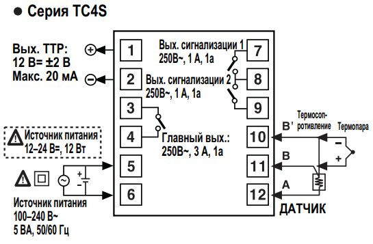
Как видно на схеме – питание подключается к контактам 5 и 6, Температурный датчик к контактам 10,11,12. Твердотельное реле с управляющим сигналом 12 вольт к контактам 1 и 2. Если для управления используется реле – контакты 3 и 4.
Определим тип подключенной термопары. Прибор поддерживает работу с семью типами датчиков. Датчики разделяются на два типа – это термосопротивления и термоэлектрические преобразователи (термопары). Термосопротивления имеют 3 провода. Термопары – 2. Прибор поддерживает два типа термосопротивления – PT100 и CU50. Определить тип подключенного датчика можно по маркировке, или если таковой нет – омметром. Межу выводами 12 и 10,11 при температуре окружающей среды должно быть соответствующее сопротивление. Определить тип термопар если нет маркировки сложнее, но в России как правило используется тип К. Подробно о маркировке было тут.
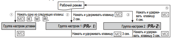
Заходим во вторую группу настроек.
Далее, делаем первичные настройки.
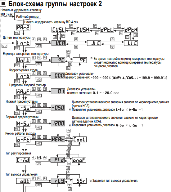
Датчик температуры – устанавливаем тип датчика. По умолчанию – К
Режим работы выхода – холодильник/нагреватель. По умолчанию – нагрев.
Тип регулирования – ПИД/ON_OFF. По умолчанию – ПИД.
Тип выхода – RLY/SSR. По умолчанию – RLY. Устанавливаем SSR если используется твердотельное реле.
Остальные настройки касаются точной и более удобной работы прибора, и как правило, не требуются.
DRW170775AA
TEMPERATURE CONTROLLER
TC4 Series
I N S T R U C T I O N M A N U A L
Thank you for choosing our Autonics product.
Please read the following safety considerations before use.
Safety Considerations
※Please observe all safety considerations for safe and proper product operation to avoid hazards.
※Safety considerations are categorized as follows.
Warning Failure to follow these instructions may result in serious injury or death.
Caution Failure to follow these instructions may result in personal injury or product damage.
※The symbols used on the product and instruction manual represent the following
symbol represents caution due to special circumstances in which hazards may occur.
Warning
1. Fail-safe device must be installed when using the unit with machinery that may cause serious injury
or substantial economic loss. (e.g. nuclear power control, medical equipment, ships, vehicles,
railways, aircraft, combustion apparatus, safety equipment, crime/disaster prevention devices, etc.)
Failure to follow this instruction may result in fire, personal injury, or economic loss.
2. Install on a device panel to use.
Failure to follow this instruction may result in electric shock or fire.
3. Do not connect, repair, or inspect the unit while connected to a power source.
Failure to follow this instruction may result in electric shock or fire.
4. Check ‘Connections’ before wiring.
Failure to follow this instruction may result in fire.
5. Do not disassemble or modify the unit.
Failure to follow this instruction may result in electric shock or fire.
Caution
2
1. When connecting the power input and relay output, use AWG 20(0.50mm
) cable or over and tighten
the terminal screw with a tightening torque of 0.74~0.90N . m.
When connecting the sensor input and communication cable without dedicated cable, use AWG
28~16 cable and tighten the terminal screw with a tightening torque of 0.74~0.90N . m.
Failure to follow this instruction may result in fire or malfunction due to contact failure.
2. Use the unit within the rated specifications.
Failure to follow this instruction may result in fire or product damage.
3. Use dry cloth to clean the unit, and do not use water or organic solvent.
Failure to follow this instruction may result in electric shock or fire.
4. Do not use the unit in the place where flammable/explosive/corrosive gas, humidity, direct sunlight,
radiant heat, vibration, impact, or salinity may be present.
Failure to follow this instruction may result in fire or explosion.
5. Keep metal chip, dust, and wire residue from flowing into the unit.
Failure to follow this instruction may result in fire or product damage.
Ordering Information
T C 4 S
1 4 R
N
Indicator — Without control output
Control output
R
Relay output+SSR drive output
2
24VAC 50/60Hz, 24-48VDC
Power supply
4
100-240VAC 50/60Hz
N
No alarm output
Sub output
1
Alarm1 output
2
Alarm1 + Alarm2 output
※2
S
DIN W48
H48mm (terminal block type)
SP
DIN W48
H48mm (11pin plug type)
Y
DIN W72
H36mm
Size
M
DIN W72
H72mm
H
DIN W48
H96mm
W
DIN W96
H48mm
L
DIN W96
H96mm
Digit
4
9999 (4 Digit)
Setting type
C
Set by touch switch
Item
T
Temperature controller
※1: In case of the AC voltage model, SSR drive output method (standard ON/OFF control, cycle control,
phase control) is available to select.
※2: It is unavailable for TC4SP, TC4Y.
※3: Sockets for TC4SP (PG-11, PS-11(N)) are sold separately.
※ The above specifications are subject to change and some models may be discontinued
without notice.
※ Be sure to follow cautions written in the instruction manual and the technical descriptions
(catalog, homepage).
Specifications
TC4 Series
Series
TC4S
TC4SP
TC4Y
TC4M
Power
AC power
100-240VACᜠ 50/60Hz
supply
AC/DC Power 24VACᜠ 50/60Hz, 24-48VDCᜡ
Allowable voltage range 90 to 110% of rated voltage
Power
AC power
Max. 5VA (100-240VAC 50/60Hz)
consumption
AC/DC Power Max. 5VA (24VAC 50/60Hz), Max. 3W (24-48VDC)
Display method
7Segment (Red), Other display (Green, Yellow, Red LED)
Character size (W×H)
7.0×15.0mm
7.4×15.0mm 9.5×20.0mm 9.5×20.0mm 7.0×14.6mm 11.0×22.0mm
Input
RTD
DPt100Ω, Cu50Ω (Allowable line resistance max.5Ω per a wire)
type
TC
K (CA), J (IC), L (IC)
At room temperature (23℃±5℃): (PV ±0.5% or ±1℃, select the higher one) ±1digit
RTD
Display
Out of room temperature range: (PV ±0.5% or ±2℃, select the higher one) ±1digit
accuracy
※1
※ For TC4SP, add ±1℃ by accuracy standard.
TC
Relay
250VACᜠ 3A 1a
Control
output
SSR
12VDCᜡ ± 2V 20mA Max.
Alarm output
AL1, AL2 Relay: 250VACᜠ 1A 1a (※TC4SP, TC4Y have AL1 only.)
Control method
ON/OFF and P, PI, PD, PID control
Hysteresis
1 to100℃/℉ (0.1 to 50.0℃/℉) variable
Proportional band (P)
0.1 to 999.9℃/℉
Integral time (I)
0 to 9999 sec.
Derivative time (D)
0 to 9999 sec.
Control period (T)
0.5 to 120.0 sec.
Manual reset
0.0 to 100.0%
Sampling period
100ms
Dielectric
AC power
2,000VAC 50/60Hz for 1min. (between input terminal and power terminal)
strength
AC/DC Power 1,000VAC 50/60Hz for 1min. (between input terminal and power terminal)
Vibration
0.75mm amplitude at frequency of 5 to 55Hz in each X, Y, Z direction for 2 hours
Mechanical
OUT: Min. 5,000,000 operations, AL1/2: Min. 5,000,000 operations
Relay
OUT: Min. 200,000 operations (250VAC 3A resistive load),
life cycle
Electrical
AL1/2: Min. 300,000 operations (250VAC 1A resistive load)
Insulation resistance
Min. 100MΩ (at 500VDC megger)
Noise immunity
Square-wave noise by noise simulator (pulse width 1㎲) ± 2KV R-phase and S-phase
Memory retention
Approx. 10 years (When using non-volatile semiconductor memory type)
Environ
Ambient temp. -10 to 50℃, Storage: -20 to 60℃
-ment
Ambient humi. 35 to 85%RH, Storage: 35 to 85%RH
Double insulation or reinforced insulation (mark:
Insulation type
measuring input part and the power part: AC power 2kV, AC/DC Power 1kV)
Approval
Approx. 141g
Approx. 123g
Approx. 174g
Approx. 204g
※2
Weight
(approx. 94g)
(approx. 76g)
(approx. 85g)
(approx. 133g)
※1: Thermocouple L (IC) type, RTD Cu50Ω
At room temperature (23℃ ±5℃): (PV ±0.5% or ±2℃, select the higher one) ±1digit
Out of room temperature range: (PV ±0.5% or ±3℃, select the higher one) ±1digit
In case of TC4SP Series, ±1℃ will be added.
※2: The weight includes packaging. The weight in parentheses is for unit only.
※Environment resistance is rated at no freezing or condensation.
Unit Description
1
1
2
3
4
2
5
8
6
7
3
5
1. Present temperature (PV) display
5. Control/alarm output indicator
RUN mode: Present temperature (PV) display.
OUT: It will turn ON when control output (Main Control
Parameter setting mode: Parameter or
Output) is ON.
parameter setting valuedisplay.
※ In case of CYCLE/PHASE control of SSR drive
output, it will turn ON when MV is over 3.0%.
2. Deviation indicator, Auto-tuning indicator
(only for AC power type)
It shows current temperature (PV) deviation
AL1/AL2: It will light up when alarm output Alarm1/
based on set temperature (SV) by LED.
Alarm2 are on.
No. PV deviation temp. Deviation display
6.
key
1
Over 2℃
indicator ON
Used when entering into parameter group, returning
2
Below ±2℃
indicator ON
to RUN mode, moving parameter, and saving setting
3
Under -2℃
indicator ON
values.
The deviation indicators (
,
,
) flash by
7. Adjustment
every 1 sec. when operating auto tuning.
Used when entering into set value change mode, digit
moving and digit up/down.
3. Set temperature (SV) indicator
Press any front key once to check or change
8. FUNCTION key
current set temperature (SV), the set
Press
+
※1
temperature (SV) indicator is ON and preset set
STOP, alarm output cancel, auto-tunning) set in inner
value is flashed.
parameter [DI-K].
※ Press
+
4. Temperature unit (℃/℉) indicator
It shows current temperature unit.
operation to move digit.
Input Sensor and Temperature Range [IN-T]
Input sensor
Display
Temperature range (℃) Temperature range (℉)
K (CA)
-50 to 1200
KCA
Thermocouple
J (IC)
-30 to 500
JIC
※3
L (IC)
LIC
-40 to 800
DPtH
-100 to 400
DPt100Ω
-100.0 to 400.0
DPtL
RTD
-50 to 200
CUsH
Cu50Ω
-50.0 to 200.0
CUsL
Installation
TC4S/SP (48
48mm) Series
TC4Y (72
36mm) Series
※ Mount the product on the panel, fasten bracket by pushing with tools as shown above.
(In case of TC4Y, fasten bolts for bracket.)
Dimensions
TC4S Series
TC4W
TC4H
TC4L
48
6
64.5
TC4Y Series
72
7
TC4M Series
72
6
64.5
Bracket
TC4S/TC4SP Series
31
48.6
20
5
45
, Dielectric strength between the
Approx. 194g
Approx. 194g
Approx. 254g
(approx. 122g)
(approx. 122g)
(approx. 155g)
15
21
55
56
6
7, 8
4
Connections
※ TC4 Series has selectable control output; Relay output, and SSR drive output.
AC/DC power type does not have SSRP function.
TC4S Series
SSR OUT:
1
7
AL1 OUT:
12VDC ±2V
250VAC 1A 1a
20mA Max
2
8
AL2 OUT:
250VAC 1A 1a
3
9
Relay OUT:
B’
RTD
250VAC 3A 1a
4
10
B
5
11
—
+
A
※1
6
12
SOURCE
SENSOR
100-240VAC 5VA 50/60Hz
24VAC 5VA 50/60Hz
24-48VDC 3W
TC4Y Series
Relay OUT:
keys for 3 sec. to operate function (RUN/
AL1 OUT:
250VAC 3A 1a
250VAC 1A 1a
1 2 3 4 5 6 7 8 9 10 11
keys at the same time in set value
A
B
B’
— +
SSR OUT:
RTD
SENSOR
12VDC ±2V
※1
SOURCE
20mA Max
100-240VAC 5VA 50/60Hz
TC
24VAC 5VA 50/60Hz
24-48VDC 3W
-58 to 2192
TC4M Series
-22 to 932
1
10
-40 to 1472
-148 to 752
2
11
-148.0 to 752.0
3
12
-58 to 392
-58.0 to 392.0
4
13
SSR OUT:
AL1 OUT:
12VDC ±2V
250VAC 1A 1a
20mA Max
5
14
AL2 OUT:
250VAC 1A 1a
6
15
Other Series
Relay OUT:
250VAC 3A 1a
B’
RTD
7
16
8
17
B
A
9
18
SOURCE
SENSOR
100-240VAC 5VA 50/60Hz
24VAC 5VA 50/60Hz
24-48VDC 3W
※Use crimp terminals or teminals of size specified below.
a b
<Round>
<Forked>
a
Min. 3.0mm
Min. 3.0mm
b
Max.5.8mm
Max.5.8mm
TC4SP Series
6
72.2
48
58.5
45
84
77
TC4H Series
48
6
64.5
Panel cut-out
TC4Y Series
30
A
60
C
TC4M, TC4W, TC4H, TC4L Series
Size
A
B
C
Model
TC4S
Min. 65
Min. 65
45
+0.6
0
TC4SP
Min. 65
Min. 65
45
+0.6
46
0
TC4Y
Min. 91
Min. 40
68
+0.7
0
TC4M
Min. 90
Min. 90
68
+0.7
0
TC4H
Min. 65
Min. 115
45
+0.6
0
TC4W
Min. 115
Min. 65
92
+0.8
0
12
TC4L
Min. 115
Min. 115
92
+0.8
0
23.9
SSR Drive Output Selection Function (SSRP Function)[SSrM]
● SSRP function is selectable one of standard ON/OFF control, cycle control, phase control by utilizing
standard SSR drive output.
TC4SP Series
● Realizing high accuracy and cost effective temperature control as linear output(cycle control and
phase control).
6
—
5
7
AL1 OUT:
● Select one of standard ON/OFF control [STND], cycle control [CYCL] , phase control [PHAS] at [SSrM]
Relay OUT
250VAC 1A 1a
parameter of Parameter group 2. For cycle control, connect zero cross turn-on SSR or random
250VAC 3A 1a
+
4
8
turn-on SSR. For phase control, connect random turn-on SSR.
SSR OUT:
12VDC ±2V
TC
RTD
B’
3
9
TC
20mA Max
—
—
Temperature controller
+
B
2
10
+
—
A
+
1
11
※1
SENSOR
SOURCE
100-240VAC 5VA 50/60Hz
24VAC 5VA 50/60Hz
24-48VDC 3W
TC4H, TC4W, TC4L Series
1
13
Power
100-240VAC
2
14
50/60Hz
3
15
※ When selecting cycle or phase control mode, the power supply for a load and a temperature
4
16
controller must be the same.
5
17
※ In case of selecting cycle [CYCL] or phase [PHAS] control mode for PID control, control cycle [T] is
not allowed to set.
6
18
※ For AC/DC power model (TC4 — 2R), this parameter [SSrM] is not displayed and it is available only
7
19
standard control by relay or SSR.
SSR OUT:
AL1 OUT:
12VDC ±2V
250VAC 1A 1a
20mA Max
8
20
1)Standard ON/OFF control [STND]
AL2 OUT:
250VAC 1A 1a
A mode to control the load in the
9
21
same way as Relay output type.
Relay OUT:
250VAC 3A 1a
B’
RTD
TC
10
22
(ON: output level 100%,
—
OFF: output level 0%)
+
B
11
23
—
+
A
2)Cycle control [CYCL]
12
24
※1
SENSOR
SOURCE
A mode to control the load by
100-240VAC 5VA 50/60Hz
24VAC 5VA 50/60Hz
repeating output ON / OFF
24-48VDC 3W
according to the rate of output
TC
※1: AC power: 100-240VAC 5VA 50/60Hz
—
within setting cycle.
AC/DC power: 24VAC 5VA 50/60Hz
+
Having improved ON / OFF noise
24-48VDC 3W
feature by Zero Cross type.
3)Phase control [PHAS]
A mode to control the load by
a
controlling the phase within
AC half cycle. Serial control is
a b
c
b
available.
<Crimp terminal>
(unit: mm)
Random turn-on SSR must be
Terminal number
a
b
c
used for this mode.
1 to N
6
Max. 1.9
Max. 4.0
(unit: mm)
TC4W Series
96
6
64.5
TC4L Series
96
6
64.5
Terminal cover (sold separately)
RSA-COVER (48×48mm)
RMA-COVER (72×72mm)
70
3
48.4
9.8
22.5
D
RHA-COVER
RLA-COVER (96×96mm )
(48×96mm, 96×48mm )
45
47.2
4
94
3
+0.6
0
45
+0.6
0
31.5
+0.5
0
68
+0.7
0
92
+0.8
0
45
+0.6
0
92
+0.8
0
SSR voltage output
SSR module
(TC4Series)
(12VDC)
Load
AC
OUT
ON
OFF
ON
OFF
AC
OUT
50Cycle
50Cycle
50%
80%
AC
OUT
10%
50%
Температурные контроллеры серии «TC4S» – популярная серия регуляторов, реализуемых компанией «Autonics». Приборы завоевали популярность в России за счет ряда преимуществ, по сравнению с имеющимися на рынке аналогами.
Давайте рассмотрим преимущества серии:
– Качество исполнения. За шесть лет, что мы работаем с продукцией Autonics, мы накопили статистику неисправностей, и на сегодняшний день она составила примерно 1:1000.
– Грамотная внутренняя программа контроллера,которая без дополнительных настроек управляет даже инерционными объектами.
– Цена. Наиболее популярная модель:
– Наличие универсальных управляющих выходов. Для управления используется как «сухой контакт» реле, так и напряжение 12 V/DC.
– Наличие дополнительного выхода сигнализации. При необходимости, выход можно использовать для подключения дополнительных функций.
Из условных недостатков, можно отметить только наличие плёночной клавиатуры. Такие клавиатуры не очень рекомендованы при интенсивной эксплуатации. Например, до сотни нажатий в день. В таком случае, следует остановится на серии «TC4Y». У этой серии кнопки выполнены из резины.
Как показала статистика обращений в поддержку, проблемы при использовании возникают крайне редко. Об ошибках, возникающих при эксплуатации мы уже останавливались в предыдущем выпуске нашего блога. Проблемы возникают при подключении новых приборов покупателями, не имеющими опыта эксплуатации и настройке приборов.
Краткая инструкция предназначена для ввода в эксплуатацию новых приборов покупателями не имеющими опыта работы.
Некоторые, специфические настройки не оговариваются. Речь будет идти о стандартной схеме — управляющий прибор с датчиком температуры, к которому через исполнительный механизм подключена управляемая нагрузка. В нашем случае — нагреватель.
Прежде всего, советуем скачать в нашем файловом архиве полную актуальную инструкцию производителя на русском языке для температурных контроллеров серии TC. Некоторые встречающиеся в сети инструкции не дают полного представления о меню и вводят из-за этого пользователя в заблуждение.
Пройдем по основным пунктам. Ниже вы видите скрин инструкции, на которой выделены параметры которые необходимо просмотреть при первичных настройках прибора.
Для начала, давайте определим как был подключен прибор. Это важно при дальнейшей настройке.
На рисунке ниже – схема подключения прибора.
Как видно на схеме – питание подключается к контактам 5 и 6, Температурный датчик к контактам 10,11,12. Твердотельное реле с управляющим сигналом 12 вольт к контактам 1 и 2. Если для управления используется реле – контакты 3 и 4.
Определим тип подключенной термопары. Прибор поддерживает работу с семью типами датчиков. Датчики разделяются на два типа – это термосопротивления и термоэлектрические преобразователи (термопары). Термосопротивления имеют 3 провода. Термопары – 2. Прибор поддерживает два типа термосопротивления – PT100 и CU50. Определить тип подключенного датчика можно по маркировке, или если таковой нет – омметром. Межу выводами 12 и 10,11 при температуре окружающей среды должно быть соответствующее сопротивление. Определить тип термопар если нет маркировки сложнее, но в России как правило используется тип К. Подробно о маркировке было тут.
Заходим во вторую группу настроек.
Далее, делаем первичные настройки.
Датчик температуры – устанавливаем тип датчика. По умолчанию – К
Режим работы выхода – холодильник/нагреватель. По умолчанию – нагрев.
Тип регулирования – ПИД/ON_OFF. По умолчанию – ПИД.
Тип выхода – RLY/SSR. По умолчанию – RLY. Устанавливаем SSR если используется твердотельное реле.
Остальные настройки касаются точной и более удобной работы прибора, и как правило, не требуются.
* Изображения служат только для ознакомления,
см. техническую документацию
от 2 шт. —
7 700 руб.
от 20 шт. —
по запросу
Добавить в корзину 1 шт.
на сумму 8 260 руб.
Номенклатурный номер: 9000179749
Артикул: TC4S-14R
Страна происхождения: КИТАЙ
Бренд / Производитель: Autonics

Описание
Температурные контроллеры серии TC4 — это одни из самых экономичных, но вместе с тем функционально усовершенствованных средств контроля температуры. Благодаря новейшему алгоритму ПИД-регулирования и исключительно короткому интервалу измерений (100 мс), контроллеры данной серии обеспечивают идеальное регулирование температуры.
Среди ключевых преимуществ серии ТС4 — поддержка выхода ТТРФУ и релейного выхода, за счет чего и достигается эффективность и экономичность регулирования, а также улучшенная читаемость дисплея и компактное исполнение.
Термоконтроллеры серии Autonics TC4 внесены в Госреестр СИ РФ за № 74166 -19. Срок окончания действия Официального Свидетельства определен до 26.02.2024 г. Установлен межповерочный интервал — 2 года.
С данными термоконтроллерами рекомендуется использовать термопары и термометры сопротивления производства Autonics серий TW-E, TW-N, TW-R, TW-S и TW-V.
Отличительные особенности
- Короткий интервал измерений: 100 мс;
- Объединенные выход ТТРФУ и релейный выход; выход ТТРФУ предоставляет возможность фазового и циклического управления;
- Повышенная читаемость показаний благодаря большому дисплею и высокой яркости светодиодов;
- Компактная конструкция не требует много места для монтажа: глубина уменьшена на 38% (60 мм) по сравнению с предыдущими моделями;
- Возможности индикации рассогласований между текущим значением и уставкой
Технические параметры
| Способ монтажа | Щитовой | |
| Цвет | серый | |
| Высота, мм | 48 | |
| Глубина | 70 | |
| Ширина | 48 | |
| Номинальное Напряжение, В | 100-240 | |
| С регулировкой температуры | да | |
| Индикация фактической температуры | да | |
| Электронное управление | да | |
| Вес, г | 200 | |
Техническая документация
Сроки доставки
Доставка в регион Курск
| Магазин «ЧИП и ДИП» | 28 апреля1 | бесплатно |
| Курьер | 27 апреля1 | 416 руб.2 |
| ПВЗ Boxberry | 26 апреля1 | 99 руб.3 |
| ПВЗ СДЭК | 27 апреля1 | 99 руб.3 |
| ПВЗ Л-Пост | 27 апреля1 | 99 руб.3 |
| ПВЗ 5Post | 28 апреля1 | 99 руб.2 |
| ТК DPD | 26 апреля1 | 546 руб.2 |
| ТК «Деловые линии» | 27 апреля1 | 824 руб.2 |
| Почта России | 10 мая1 | 286 руб.2 |
Цена и наличие в магазинах
| ул. Карла Маркса, 68, ТЦ «Мега Гринн», 1 этаж | нет в наличии |
Розничная цена: 8 260 руб.
780 руб.
13 970 руб.
31 990 руб.
1 250 руб.
4 280 руб.