- Manuals
- Brands
- Pentair Manuals
- Water Filtration Systems
- AUTOTROL MAGNUM 742
- Installer manual
-
Contents
-
Table of Contents
-
Troubleshooting
-
Bookmarks
Quick Links
AUTOTROL
MAGNUM 742-762
INSTALLER
MANUAL
WATER PURIFICATION
Related Manuals for Pentair AUTOTROL MAGNUM 742
Summary of Contents for Pentair AUTOTROL MAGNUM 742
-
Page 1
AUTOTROL MAGNUM 742-762 INSTALLER MANUAL WATER PURIFICATION… -
Page 2: Table Of Contents
Installer Manual Magnum 742-762 — Table of content Table of content Generalities ……… . 6 1.1.
-
Page 3
Installer Manual Magnum 742-762 — Table of content System sizing ……..29 4.1. -
Page 4
Installer Manual Magnum 742-762 — Table of content Commissioning ……..62 7.1. -
Page 5
Installer Manual Magnum 742-762 — Table of content Troubleshooting ……..85 10.1. -
Page 6: Generalities
Address change, Bleam information and valve on 23.05.2018 BRY/FLA tank assembly. 25.10.2019 General corrections. 1.3. Manufacturer identifier, product Manufacturer: Pentair International LLC Avenue de Sevelin 18 1004 Lausanne Switzerland Product: Magnum 742-762 6 / 106 Ref. MKT-IM-012 / C — 25.10.2019…
-
Page 7: Abbreviations Used
Installer Manual Magnum 742-762 — Generalities 1.4. Abbreviations used BLFC …………….. Brine Line Flow Controller DF………………Down Flow DLFC …………….. Drain Line Flow Controller Inj ………………Injector QC………………Quick Connect Regen …………….Regeneration SBV………………Safety Brine Valve TC ………………Time Clock UF………………
-
Page 8: Procedure For Technical Support
Pentair Quality System EMEA products benefit, under specific conditions, from a manufacturer warranty that may be invoked by Pentair’s direct customers. Users should contact the vendor of this product for applicable conditions and in case of a potential warranty claim.
-
Page 9: Scan & Service Application
Installer Manual Magnum 742-762 — Generalities 1.9. Scan & Service application Scan & Service mobile application is the ideal support for the maintenance person in his daily business. A simple scan of an Identification (ID) label (1) present on the valve with a smartphone gives an instantaneously access to all updated information related to the product, such as: •…
-
Page 10: Safety
Installer Manual Magnum 742-762 — Safety Safety 2.1. Safety pictograms definition Caution Warning Warns of a risk of minor injury or major Warns against serious personal injury material damage to the device or and damage to health. environment. Danger Mandatory Warns against serious personal injury or Standard or measure to apply.
-
Page 11: Personnel
Installer Manual Magnum 742-762 — Safety 2.3.1. Personnel Caution Only qualified and professional personnel, based on their training, experience and instruction as well as their knowledge of the regulations, the safety rules and operations performed, are authorized to carry out necessary work. 2.3.2.
-
Page 12: Hygiene Measures
Installer Manual Magnum 742-762 — Safety 2.4.2. Hygiene measures Disinfection • The materials used for the construction of our products meet the standards for use with potable water; the manufacturing processes are also geared to preserving these criteria. However, the process of production, distribution, assembly and installation, may create conditions of bacterial proliferation, which may lead to odor problems and water contamination;…
-
Page 13: Description
Installer Manual Magnum 742-762 — Description Description 3.1. Introduction to the Magnum Cv and Magnum IT valves series The Magnum valve is available in several configurations: Magnum Cv Magnum IT Turbine External turbine Internal turbine Inlet diameter 3.91 cm (1 ½») 5.08 cm (2″) Outlet diameter 3.91 cm (1 ½»)
-
Page 14: Technical Specifications
* Valve installed drain flow controls available (1.14 — 9.08 m /h). If higher backwash flow is needed, an external flow control will be required. Electrical Controller Operating Voltage ……….12 VAC (requires use of Pentair Water supplied transformer) Input Supply Frequency………….50 or 60 Hz Motor Input Voltage …………12 VAC Controller Power Consumption ……..3 W average…
-
Page 15: Performance Flow Rate Characteristics
Installer Manual Magnum 742-762 — Description 3.2.1. Performance flow rate characteristics The graph shows the pressure drop created by the valve itself at different flow rates. It makes it possible to predetermine the maximum flow rate going through the valve depending on the system settings (inlet pressure etc).
-
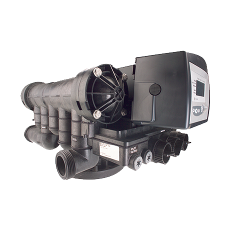
Page 16: Outline Drawing
Installer Manual Magnum 742-762 — Description 3.3. Outline drawing Magnum CV Magnum IT 16 / 106 Ref. MKT-IM-012 / C — 25.10.2019…
-
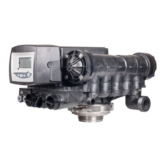
Page 17: Description And Components Location
Installer Manual Magnum 742-762 — Description 3.4. Description and components location Camshaft No hard water bypass valve cartridge Drain Optical sensor Inlet valve cartridge Outlet Motor Inlet LCD display Manual REGEN button UP button Pilot filter screen SET button Injector assembly DOWN button Valve disc spring Refill control assembly…
-
Page 18: Options Available On The Valve
Installer Manual Magnum 742-762 — Description 3.5. Options available on the valve 3.5.1. 6″ flange plastic tank adapter This adapter allows a direct connection from the 6″ flanged tank to the Magnum valve. It is manufactured from the same glass-filled thermoplastic as the Magnum valve body. When incorporating this adapter into your system, no metal components are in contact with the water flowing through which enables the Magnum Control Valve’s use in corrosive applications.
-
Page 19: Refill First
Installer Manual Magnum 742-762 — Description 3.5.2. Refill first The logix 742 and 762 controllers allow you to refill the brine tank first when used in softener mode. This feature allows the brine tank to be dry during the complete service cycle, reducing the caking phenomena.
-
Page 20: Magnum Switch Kit
Installer Manual Magnum 742-762 — Description 3.5.4. Magnum switch kit Optional switch kits can be used on the Magnum Cv valve to provide electrical signalling capabilities. Used in conjunction with breakaway cams, the switches will provide a signal to external devices during the various cycles of the valve operations.
-
Page 21
Installer Manual Magnum 742-762 — Description Picture 1 Picture 2 Picture 3 Picture 4 Ref. MKT-IM-012 / C — 25.10.2019 21 / 106… -
Page 22
Installer Manual Magnum 742-762 — Description 3.5.4.2 Breakaway switch cam description The breakaway switch cam has been divided into 36 equal sections with each section representing approximately 10-degrees of the cam rotation. Each section is consecutively numbered 1 through 36 to aid in customized cam operating design. -
Page 23
Installer Manual Magnum 742-762 — Description 3.5.4.3 Breakaway switch cam instructions Based on the system requirements and the external devices used, determine the program timing, ie., when the external devices need to operate, either open or close. Typical external devices would be solenoids, solenoid operated diaphragm valves, relays, and chemical feed pumps. -
Page 24
Installer Manual Magnum 742-762 — Description Picture 1 Example : Removing sections 36 to 13 in a clockwise direction will provide an electrical signal during the slow rinse cycle. 10 degrees = 1 section Clockwise Picture 2 Untrimmed Trimmed 24 / 106 Ref. -
Page 25: Hydraulic Output Signal
Installer Manual Magnum 742-762 — Description 3.5.5. Hydraulic output signal An optional hydraulic output signal is available on the valve. An optional cam lobe on pilot valve #6 is used on the camshaft assembly to initiate the hydraulic output signal during regeneration or backwash.
-
Page 26: Systems Regeneration Cycle
Installer Manual Magnum 742-762 — Description 3.6. Systems regeneration cycle 3.6.1. 298 Valves (5 — Cycle softener) Service — cycle C0 Untreated water is directed down through the resin bed and up through the riser tube. The hardness ions attach themselves to the resin and are removed from the raw water being exchanged on the resin beads towards sodium ions.
-
Page 27
Installer Manual Magnum 742-762 — Description Valve Valve BACKWASH SERVICE From brine tank Valve Valve BRINE/SLOW RINSE FAST RINSE C2 and C3 To brine tank Valve BRINE REFILL Ref. MKT-IM-012 / C — 25.10.2019 27 / 106… -
Page 28: Valves (3 — Cycle Filter)
Installer Manual Magnum 742-762 — Description 3.6.2. 293 Valves (3 — Cycle filter) Service — cycle C0 Untreated water is direct down through the conditioning media and up through the riser tube, then out to the system. Backwash — cycle C1 The flow of water is reversed by the valve and directed down the riser tube and up through the conditioning media.
-
Page 29: System Sizing
Installer Manual Magnum 742-762 — System sizing System sizing 4.1. Recommendations 4.1.1. Injector and Refill controller charts Injector Flow control Refill flow control Backwash flow control Vessel diameter [In] [gpm] [gpm] [gpm] 10.0 14.0 21.0 30.0 Note All flow rates are based on an inlet pressure of 413 kPA. Actual rates vary with pressure, temperatures and other system variables.
-
Page 30
Installer Manual Magnum 742-762 — System sizing Flow control disc Insert 1 Insert 2 Insert 3 Insert 4 [gpm] 4.313 White Orange Black Black 4.54 Blue Blue Blue Blue 4.767 Brown Brown Brown Black 4.994 Green Green Black 5.221 Green Green Brown Black… -
Page 31: Recommended Backwash Flow Rates For Various Media
Installer Manual Magnum 742-762 — System sizing 4.1.3. Recommended backwash flow rates for various media Tank diameter 14″ 16″ 18″ 21″ 24″ 30″ 36″ Media (35.6 cm) (40.6 cm) (45.7 cm) (53.3 cm) (61.0 cm) (76.2 cm) (91.4 cm) Tank Tank Tank Tank…
-
Page 32: Injector Flow Rates (Tables)
Installer Manual Magnum 742-762 — System sizing 4.3. Injector flow rates (tables) The following tables represent the injectors flow rate as a function of the inlet pressure for the different injector sizes. TOTAL BRINE DRAW RINSE Injector 1000442 Injector 1000441 For 16″…
-
Page 33
Installer Manual Magnum 742-762 — System sizing TOTAL BRINE DRAW RINSE Injector 1000446 Injector 1000445 For 30″ Tanks For 24″ Tanks Injector 1000447 For 36″ Tanks Ref. MKT-IM-012 / C — 25.10.2019 33 / 106… -
Page 34: Standard Efficiency Exchange Capacity
Installer Manual Magnum 742-762 — System sizing 4.4. Standard efficiency exchange capacity Salt [grams/liter] Exchange capacity [grams/liter] 29.9 34.0 37.5 40.6 43.4 45.9 48.2 50.2 52.1 53.8 55.5 58.5 62.7 66.9 71.0 75.3 34 / 106 Ref. MKT-IM-012 / C — 25.10.2019…
-
Page 35: Installation
Installer Manual Magnum 742-762 — Installation Installation 5.1. Safety notices for installation • Observe all warnings that appear in this manual; • only qualified and professional personnel are authorized to carry out installation work. 5.2. Installation environment 5.2.1. General • Use only brine salts designed for water softening.
-
Page 36: Mechanical
Installer Manual Magnum 742-762 — Installation 5.2.3. Mechanical • Do not use petroleum-based lubricants such as vaseline, oils, or hydrocarbon-based lubricants. Use only 100% silicone lubricants; • all plastic connections should be hand tightened. PTFE (plumber’s tape) may be used on connections that do not use an o-ring seal.
-
Page 37: Integration Constraints
Installer Manual Magnum 742-762 — Installation 5.3. Integration constraints Location of a water treatment system is important. The following conditions are required: • level platform or floor; • room to access equipment for maintenance and adding brine (salt) to tank; •…
-
Page 38
Installer Manual Magnum 742-762 — Installation Inlet valve Outlet valve Drain line flow control Drain Manual bypass valve Logix controller Turbine 1.5″ Riser tube Brine line Hub & Lateral Brine tank Magnum Cv Configuration example Magnum IT 38 / 106 Ref. -
Page 39: Valve Connection To Piping
Installer Manual Magnum 742-762 — Installation 5.5. Valve connection to piping The connections should be hand tightened using PTFE (plumber’s tape) on the threads if using the threaded connection type. In case of heat welding (metal type connection), the connections should not be made to the valve when soldering.
-
Page 40
• in any case, any failure caused by improper installations and/or piping connections may void the warranty of Pentair products; • in the same way, using lubricant* on the valve thread is not allowed and will void the warranty for the valve and tank. -
Page 41: Side-Mounted Valve Installation
Installer Manual Magnum 742-762 — Installation 5.5.2. Side-mounted valve installation Use a 2″ BSP side mount adapter assembly for the installation. Side mount adapter • Valid for location having a reduced height; • to avoid the piping supporting the valve and side adapter weight, they must be fixed on a tripod or any other appropriate support;…
-
Page 42: Connections (Electrical)
Installer Manual Magnum 742-762 — Installation 5.6. Connections (electrical) Lockout connection (764 only) Chlorine generator outlet (EU versions only) AC transformer input (low voltage) Main motor & optical sensor connection Sensor input for turbine 760/762 Dry contact signal input 740/742 Secondary valve motor control (764 only) 5.7.
-
Page 43: Drain Line Connection
Installer Manual Magnum 742-762 — Installation Caution Do not solder pipes with lead-based solder. Caution Do not use tools to tighten plastic fittings. Over time, stress may break the connections. Caution Do not use petroleum grease on gaskets when connecting bypass plumbing. Use only 100% silicone grease products when installing any plastic valve.
-
Page 44: Overflow Line Connection
Installer Manual Magnum 742-762 — Installation Air gap Drain 5.9. Overflow line connection In the event of a malfunction, the brine tank overflow fitting will direct “overflow” to the drain instead of spilling on the floor. This fitting should be on the side of the cabinet or brine tank. Most tank manufacturers include a post for the tank overflow connector.
-
Page 45: Programming
Installer Manual Magnum 742-762 — Programming Programming 6.1. Display 1. Hourglass Displayed when the motor is running. The camshaft should be turning. 2. Cursor These cursors appear next to the item that is currently displayed. 3. Days of the week Displayed days of the week.
-
Page 46
Installer Manual Magnum 742-762 — Programming 9. «PM» Indicates that the time displayed is between 12:00 noon and 12:00 midnight. «PM» indicator is not used if the clock mode is set to 24-hour (there is no AM indicator). 10. «MIN» Indicates that the value entered/displayed is in minute increments. -
Page 47: Commands
Installer Manual Magnum 742-762 — Programming 6.2. Commands Scrolls down or decrement through a group of choices. — Down arrow Accepts a setting that normally becomes stored in memory. — Set Also used together with the arrow buttons to access special features. Scrolls up or increment through a group of choices.
-
Page 48: Basic Programming
Installer Manual Magnum 742-762 — Programming 6.3. Basic programming Note Menus are displayed in a defined and incremental order. 6.3.1. Basic programming mode chart 742-762/298 valve type Default Units of Parameter description Range of values Notes value measure 255, 263, 268, Program valve type 278 and None…
-
Page 49: Basic Programming Mode Chart 742F-762F/293 Valve Type
Installer Manual Magnum 742-762 — Programming 6.3.2. Basic programming mode chart 742F-762F/293 valve type Default Units of Parameter description Range of values Notes value measure 255, 263, 268, Program valve type 278 and None Magnum series Program system size 5 — 100 / F None liters 1:00 — 12:59 AM…
-
Page 50: Basic Programming 742 — 762/298 Valve Type
Installer Manual Magnum 742-762 — Programming 6.3.3. Basic programming 742 — 762/298 valve type 6.3.3.1 Program valve type Set your valve type through the options. to scroll though valve type choices. → Valve type flashes. Choose the 298 valve type. Press to validate the valve type selected and advance to the next parameter using…
-
Page 51
Installer Manual Magnum 742-762 — Programming 6.3.3.4 Day of week Set the current day of the week. Press → Arrow flashes. Select displayed day with Press to validate the selection and advance to the next parameter using 6.3.3.5 Regeneration time Set the time when regeneration will take place. -
Page 52
Installer Manual Magnum 742-762 — Programming 6.3.3.8 Amount of brine used per regeneration Set desired brine amount in g/L. Press → Setting flashes. Adjust displayed settings with Press to validate the selection and advance to the next parameter using 6.3.3.9 Estimated system capacity Note… -
Page 53: Basic Programming 742F — 762F/293 Valve Type
Installer Manual Magnum 742-762 — Programming 6.3.4. Basic programming 742F — 762F/293 valve type 6.3.4.1 Program valve type Set your valve type through the options. to scroll though valve type choices. → Valve type flashes. Choose the 293 valve type. Press to validate the system size selected and advance to the next parameter using…
-
Page 54
Installer Manual Magnum 742-762 — Programming 6.3.4.5 Time of backwash Set the time of backwash cycle (C1). Press → Backwash time flashes. Adjust displayed time with Press to validate the selection and advance to the next parameter using 6.3.4.6 Days override (762F controller only) Set the number of days for calendar override. -
Page 55: Advanced Programming
Installer Manual Magnum 742-762 — Programming 6.4. Advanced programming Note Press and hold for 5 seconds to access advance programming. A «P» symbol is displayed on the bottom left of screen. 6.4.1. Basic programming parameters (5 — Cycle softener system) Default Units of Parameter description…
-
Page 56: Advanced Programming Parameters (5 — Cycle Softener System)
Installer Manual Magnum 742-762 — Programming 6.4.2. Advanced programming parameters (5 — Cycle softener system) Default Units of Parameter description Range of values Notes value measure 0 = US unit. Units of measure 0 — 1 1= Metric unit. 0 = 12 hour clock. P10 Clock mode 0 — 1 1 = 24 hour clock.
-
Page 57: Basic Programming Parameters (3 — Cycle Filter System)
Installer Manual Magnum 742-762 — Programming 6.4.3. Basic programming parameters (3 — Cycle filter system) Default Units of Parameter description Range of values Notes value measure 1:00 — 12:59AM Hour : Range depends on value Time of day 12:00 PM 0:00 — 23:59PM minute selected for P10.
-
Page 58: Advanced Programming Parameters (3 — Cycle Filter System)
Installer Manual Magnum 742-762 — Programming 6.4.4. Advanced programming parameters (3 — Cycle filter system) Default Units of Parameter description Range of values Notes value measure 0 = US unit. Units of measure 0 — 1 1= Metric unit. 0 = 12 hour clock. P10 Clock mode 0 — 1 1 = 24 hour clock.
-
Page 59: Cycle Time Programming
Installer Manual Magnum 742-762 — Programming 6.4.5. Cycle time programming Press and hold the for 5 seconds when the controller is not in regeneration to enter cycle time programming. → A small “C#” with a number will be displayed indicating the controller is in cycle time programming.
-
Page 60: Diagnostic
Installer Manual Magnum 742-762 — Programming 6.4.6. Diagnostic To access diagnostic values, press and hold for 5 seconds to view the «H» levels. Diagnostic Description Unit Range Code Resin Initial setting value Litre Volume Days since last regeneration 0 — 255 Current flow rate Depends on turbine used Water used today since time of regeneration…
-
Page 61: Resetting The Controller
Installer Manual Magnum 742-762 — Programming 6.4.7. Resetting the controller Caution Resetting the controller will delete all information stored in its memory, except the time and day. This will require you to reprogram the controller completely from the initial power-up mode.
-
Page 62: Commissioning
Installer Manual Magnum 742-762 — Commissioning Commissioning Note This chapter is available for standard regeneration types. Contact your supplier if the actual regeneration is not standard and if you need assistance. 7.1. Water filling, draining and waterproofness inspection 7.1.1. Activating the softener After you have performed the previous initial programming steps, you will need to activate the softener.
-
Page 63
Installer Manual Magnum 742-762 — Commissioning 5. Add water to the brine tank (initial fill) (softener and 3-cycle filters only). → With a bucket or hose, add approximately 15 liters (4 gallons) of water to the brine tank. If the tank has a salt platform in the bottom of the tank, add water until the water level is approximately 25 mm (1″) above the platform. -
Page 64: Additional Tips
Installer Manual Magnum 742-762 — Commissioning 7.1.2. Additional tips • When the controller is first plugged in, it may display a flashing hourglass and the message «Err 3», this means that the controller is rotating to the home position. If the «Err 2» is displayed, check that the incoming power frequency matches the controller;…
-
Page 65: Sodium Or Calcium Hypochlorite
Installer Manual Magnum 742-762 — Commissioning 7.2.2. Sodium or calcium hypochlorite These materials are satisfactory for use with polystyrene resins, synthetic gel zeolite, greensand and bentonites. 5.25% Sodium hypochlorite If stronger solutions are used, such as those sold for commercial laundries, adjust the dosage accordingly.
-
Page 66: Operation
Installer Manual Magnum 742-762 — Operation Operation During a regeneration: • A «C#» is displayed to show the current cycle; • total regeneration time remaining is displayed on screen; • you can press and hold to show current cycle time remaining. Note…
-
Page 67: To Advance Regeneration Cycles
Installer Manual Magnum 742-762 — Operation Double regeneration After an immediate regeneration has begun, press again to plan a second manual regeneration. → A flashing «x2» symbol indicates the second regeneration will start at the programmed delayed regeneration time. Immediate double regeneration Press and hold to start the second regeneration immediately following the current regeneration.
-
Page 68: Maintenance
Installer Manual Magnum 742-762 — Maintenance Maintenance Mandatory Cleaning and maintenance shall take place at regular intervals in order to guarantee the proper functioning of the complete system, and be documented in the Maintenance chapter in the User Guide document. Mandatory…
-
Page 69: Regeneration Test
Installer Manual Magnum 742-762 — Maintenance 9.1.3. Regeneration test 1. Initiate manual regeneration and overserve flow to drain. 2. Make sure flow rate correspond to DLFC configuration. 3. Check for media loss at the drain during backwash. 4. Check to see if water runs clear at the end of the backwash cycle. 5.
-
Page 70
Installer Manual Magnum 742-762 — Maintenance Items 1 year 2 year 3 year 4 year 5 year Internal Check/clean/ Check/clean/ Check/clean/ Check/clean/ Turbine replace if replace if Replace replace if replace if (IT models, if necessary necessary necessary necessary present)*** External Turbine… -
Page 71: Cv / It: General System Inspection
Installer Manual Magnum 742-762 — Maintenance 9.3. 298 CV / IT: General system inspection Mandatory Has to be done once a year at minimum. 9.3.1. Water quality 1. Raw water total hardness. 2. Treated water hardness. 9.3.2. Mechanical Checks 1. Inspect general condition of valve and associated ancillaries and check for any leaks, ensure valve connection to piping is made with adequate flexibility as per manufacturer instruction.
-
Page 72: Cv / It: Recommended Maintenance Plan
Installer Manual Magnum 742-762 — Maintenance 9.4. 298 CV / IT: Recommended maintenance plan Items 1 year 2 year 3 year 4 year 5 year Injector & Clean / replace Clean Clean Clean Clean filter if necessary Refill Clean / replace Clean Clean Clean…
-
Page 73
Installer Manual Magnum 742-762 — Maintenance Items 1 year 2 year 3 year 4 year 5 year Internal Check/clean/ Check/clean/ Check/clean/ Check/clean/ Turbine replace if replace if Replace replace if replace if (IT models, if necessary necessary necessary necessary present)*** External Turbine… -
Page 74: Recommendations
Installer Manual Magnum 742-762 — Maintenance 9.5. Recommendations 9.5.1. Use original spare parts Caution To ensure correct operation and safety of the device, only use original spare parts and accessories recommended by the manufacturer. Parts to keep in stock for potential replacements are motor and optical sensor, controller, transformer, injectors, flapper kit, O-ring kit, refill and DLFC.
-
Page 75: Injector Cleaning
Installer Manual Magnum 742-762 — Maintenance 9.6.2. Injector cleaning Operation Using a pliers if needed, unscrew and remove the injector cap (1). Caution Take care not to damage the injector (3). Check for O-rings integrity. Clean the screen injector (2) and injector (3) using compressed air, a soft brush or possibly a pin.
-
Page 76: Pilot Filter Screen Cleaning
Installer Manual Magnum 742-762 — Maintenance 9.6.4. Pilot filter screen cleaning Operation Using a Torx key, unscrew and extract the injector screen cap (1). Unclip the white plastic basket (2) and clean it with a soft brush. Use of descaling agent such as white vinegar might be required in case of impurities on the plastic basket (2).
-
Page 77: Controller Cover Disassembly
Installer Manual Magnum 742-762 — Maintenance 9.6.5. Controller cover disassembly Operation Unlock the controller cover (1) from the slide clips (4) (one on each side of the valve). Pull straight off the controller cover (1). Reverse above procedure steps to rebuild. 9.6.6.
-
Page 78: Motor Replacement
Installer Manual Magnum 742-762 — Maintenance 9.6.7. Motor replacement Operation Remove the controller cover (1). See 9.6.5. Controller cover disassembly, page 77. Press the controller locking pad (4) and slide the controller (2) out of its position. Loosen the two screws (6). Remove the motor (5).
-
Page 79: Camshaft Replacement
Installer Manual Magnum 742-762 — Maintenance 9.6.8. Camshaft replacement Operation Remove the camshaft cover (1). See 9.6.6. Camshaft cover disassembly, page 77. Press on the release tab (9) and pull on the back end of the camshaft (2). The front end of the camshaft will be flush with the mounting plate (6). Loosen the four screws and 5).
-
Page 80: Optical Sensor And Controller Replacement
Installer Manual Magnum 742-762 — Maintenance 9.6.9. Optical sensor and controller replacement Operation Remove the controller cover (1). See 9.6.5. Controller cover disassembly, page 77. Press the controller locking pad (3) and slide the controller (2) out of its position. Loosen the four screws (4).
-
Page 81: Turbine Cleaning Or Replacement
Installer Manual Magnum 742-762 — Maintenance 9.6.10. Turbine cleaning or replacement Operation Note Depending on the valve installation, the turbine may not be present in the valve. (Magnum IT : internal turbine/Magnum Cv : external turbine). Using a pliers if needed, unscrew and remove the turbine (3) from the outlet pipe (1) of the valve.
-
Page 82: Top Plate And Disc Valve Replacement
Installer Manual Magnum 742-762 — Maintenance 9.6.11. Top plate and disc valve replacement Operation Remove the camshaft cover. See 9.6.6. Camshaft cover disassembly, page 77. Remove the camshaft. See 9.6.8. Camshaft replacement, page 79. Caution Take care with sharp edges. Use of protective glove is highly recommended to release or remove the springs (1).
-
Page 83: Cartridge Replacement
Installer Manual Magnum 742-762 — Maintenance 9.6.12. Cartridge replacement Operation Note Removal of cartridges should be done only after reviewing all other possible causes of problem (see 10.3. Magnum valve cartridge, page 88). Note There may be some difficulties to remove cartridges in valves that have been in service for a long period of time.
-
Page 84: Valve On Tank Assembly
Installer Manual Magnum 742-762 — Maintenance 9.6.13. Valve on tank assembly Operation Lubricate the seals with approved silicone grease. Spin the valve (1) onto the tank (2), ensuring the threads are not cross-threaded. Rotate the valve (1) clockwise and freely, without using force until it comes to a stop. Note…
-
Page 85: Troubleshooting
Installer Manual Magnum 742-762 — Troubleshooting Troubleshooting 10.1. Logix controller Err. code Cause Reset and recovery Controller power has been connected Reset controller. ERR 1 and the controller is not sure of the See 6.4.7. Resetting the controller, operating status. page 61.
-
Page 86: Magnum It And Cv Valve
Installer Manual Magnum 742-762 — Troubleshooting Err. code Cause Reset and recovery If motor keeps rotating indefinitely, replace the following components in this order: • wire harness; Camshaft rotates for more than 5 • motor; ERR3 minutes to find Home position. •…
-
Page 87
Installer Manual Magnum 742-762 — Troubleshooting Issue Cause Reset and recovery • Inspect and clean the injector and/ Plugged injector and/or injector or injector screen assembly. screen. • Increase water pressure above Insufficient water pressure. 172 kPa minimum. No brine draw. •… -
Page 88: Magnum Valve Cartridge
Installer Manual Magnum 742-762 — Troubleshooting Issue Cause Reset and recovery • Clean Magnum control valve and Fouled resin bed due to iron mineral bed with cleaner. accumulation. Loss of water pressure. • Inspect and clean distributor pipe Slots in riser pipe or laterals are filled slots as needed.
-
Page 89
Installer Manual Magnum 742-762 — Troubleshooting There are four symptoms that may require a cartridge to be removed and inspected or replaced. 1. A constant leak from the pilot drain in any cycle position. A small discharge of water from the pilot drain while transitioning from one cycle to the next is normal. -
Page 90: Spare Parts
Installer Manual Magnum 742-762 — Spare parts Spare parts 11.1. Magnum Logix valve body Assembly Item Part number Description quantity Magnum Cv valve body cartridges, HWB / UWB, Magnum Logix 3007801 single camshaft Magnum Cv valve body cartridges, NHB / NUB, Magnum Logix 3007803 single camshaft Magnum IT valve body cartridges, HWB / UWB, Magnum Logix…
-
Page 91: Magnum Connections
Installer Manual Magnum 742-762 — Spare parts 11.2. Magnum connections Assembly Item Part number Description quantity 1001655 Magnum Cv 1 ½» — 1 ½» PVC adapter kit 1001656 Magnum Cv 1 ½» — 50 mm PVC adapter kit 3023674 Magnum IT/Cv plus 2″ — 2″ BSP adapter kit 1040784 Magnum IT/Cv plus 2″…
-
Page 92: Magnum Logix Camshaft And Pilot
Installer Manual Magnum 742-762 — Spare parts 11.3. Magnum Logix camshaft and pilot Assembly Item Part number Description quantity 1000589 Pillow block cap 1267726 Camshaft logix Magnum single tank 1000341 Shaft, cam, Magnum 1000339 Top plate 3018941 Pillow block and top plate screw (long) 1000391 Brine flapper valve 1000328…
-
Page 93: Magnum Refill Controller Assembly
Installer Manual Magnum 742-762 — Spare parts 11.4. Magnum refill controller assembly Assembly Item Part number Description quantity 1040688 Flow controller plug 1041687 Refill controller assembly 1000421 Refill flow controller for 14″ tank — 0.7 gpm (0.16 m 1000422 Refill flow controller for 16″ tank — 0.8 gpm (0.18 m 1000423 Refill flow controller for 18″…
-
Page 94: Magnum Injector Assembly
Installer Manual Magnum 742-762 — Spare parts 11.5. Magnum injector assembly Assembly Item Part number Description quantity 1040670 Injector for 14″ tank with O-rings — 0.5 gpm (0.11 m 1040671 Injector for 16″ tank with O-rings — 0.5 gpm (0.11 m 1040672 Injector for 18″…
-
Page 95: Magnum Drain Line Flow Controls Assembly
Installer Manual Magnum 742-762 — Spare parts 11.6. Magnum drain line flow controls assembly Assembly Item Part number Description quantity Assembled DLFC without O-ring and flow controls Inserts 1040720 5 gpm (1.14 m /h) (for 14″ softener) BLU-BLK-BLK-BLK Assembled DLFC without O-ring and flow controls Inserts 1040721 6 gpm (1.36 m /h) (for 16″…
-
Page 96
Installer Manual Magnum 742-762 — Spare parts Assembly Item Part number Description quantity Assembled DLFC without O-ring and flow controls Inserts 1040741 16 gpm (3.63 m /h) GRN-GRN-BLK-BLK Assembled DLFC without O-ring and flow controls Inserts 1040742 17 gpm (3.86 m /h) WHI-GRN-BLK-BLK Assembled DLFC without O-ring and flow controls Inserts… -
Page 97
Installer Manual Magnum 742-762 — Spare parts Assembly Item Part number Description quantity Assembled DLFC without O-ring and flow controls Inserts 1040737 32 gpm (7.27 m /h) GRN-GRN-GRN-GRN Assembled DLFC without O-ring and flow controls Inserts 1040738 33 gpm (7.49 m /h) GRN-GRN-GRN-WHI Assembled DLFC without O-ring and flow controls Inserts… -
Page 98: Magnum Cartridges
Installer Manual Magnum 742-762 — Spare parts 11.7. Magnum cartridges #4 Inlet Cartridge Drain valve Rinse valve cartridge cartridge #3 Outlet Cartridge No hard water Hard water bypass valve bypass cap cartridge #2 Rinse #1 Drain Cartridge Cartridge Inlet valve cartridge Assembly Item Part number…
-
Page 99: Magnum Logix Controllers
Installer Manual Magnum 742-762 — Spare parts 11.8. Magnum Logix controllers Assembly Item Part number Description quantity 1265832 Timer Logix 742F Magnum 1265833 Timer Logix 762F Magnum 1265834 Timer Logix 742 Magnum 1265835 Timer Logix 762 Magnum 1266224 Bushing, Logix mount 1005981 Screw 1262674…
-
Page 100: Magnum It Turbine
Installer Manual Magnum 742-762 — Spare parts Assembly Item Part number Description quantity 5+6+7 Logix Magnum controller mechanical assembly 1233809 +8+9 (items #5, 6, 7, 8, 9, 10, 12) 1000813 Wall mount transformer 220 V/12 V UK 1000814 Wall mount transformer 220 V/12 V EUR 1001858 Wall transformer hard wired 12 V UK 1263718…
-
Page 101: 2″ External Turbine Assembly
Installer Manual Magnum 742-762 — Spare parts 11.10. 2″ external turbine assembly Assembly Item Part number Description quantity 1033358 2″ turbine only 3023537 2″ turbine assembly with 2″ stainless steel BSP adapters 1034080 2″ turbine assembly with 2″ PVC adapters 1034081 2″…
-
Page 102: Magnum Miscellaneous
Installer Manual Magnum 742-762 — Spare parts 11.12. Magnum miscellaneous External pilot feed adapter Switch kit Pilot filter screen assembly Pilot system check valves Assembly Item Part number Description quantity 3019468 Kit 1 switch 0.1 Amp 3019469 Kit 1 switch 5 Amp 3019467 Kit 3 switch 5 Amp 3019466…
-
Page 103: Magnum 298 Installation Components
Installer Manual Magnum 742-762 — Spare parts 11.13. Magnum 298 installation components Assembly Item Part number Description quantity Drain line flow control (refer to DLFC list, see chapter 11.6. Magnum drain line flow controls assembly, page 95) 1009115 Upper screen 3028330 Riser tube 1036846…
-
Page 104: Magnum 293 Installation Components
Installer Manual Magnum 742-762 — Spare parts 11.14. Magnum 293 installation components Assembly Item Part number Description quantity Drain line flow control (refer to DLFC list, see chapter 11.6. Magnum drain line flow controls assembly, page 95) 3028330 Riser tube 1036846 Lower distributor (for 14″…
-
Page 105: Disposal
This will help to reduce the impact on the environment, health, safety and help to promote recycling. Pentair does not collect used product for recycling. Contact your local recycling center for more information.
-
Page 106
www.pentairaquaeurope.com…
Описание
Клапан управления Autotrol Magnum является одним из самых универсальных клапанов на рынке. Он оснащен полностью электронной платформой управления с резервным питанием на базе суперконденсатора (до 24 часов).
Преимущества
- Простое и удобное программирование
- Подходит для мультиплексных систем
- Длительный срок службы
- Оптимальная цена
Краткие технические характеристики INFO
| Материал | Латунь |
| Рабочее давление | 1,8 — 8,5 бар |
| Рабочая температура | 1 — 43 °С |
| Сервисная производительность | 17,3 м3/ч |
| Обратная промывка | 20,2 м3/ч |
| Вход/выход | 1,5″, 2″ |
| Посадочное отверстие | 4,0″ |
| Рекомендуемые диаметры фильтров | 14 — 42″ |
Документация PDF
- Электрические требования к установке зависят от типа клапана управления.
- Стандартный контроллер Logix комплектуется блоком питания 12 В переменного тока. Также возможна комплектация блоками питания для: Японии – 100В/50-60 Гц, Австралии/Аргентины – 240В/50 Гц, Британии — 240В/50 Гц, Европы — 230В/50 Гц.
Установка клапана Magnum на бак
Перед сбором распределительной системы и загрузкой наполнителя, следует навернуть клапан на бак и установить его в надлежащее положение относительно стен и трубопровода. После загрузки баллона его, как правило, нельзя перемещать. Поэтому бак следует выставить заранее.
- Поместите уплотнительное кольцо в посадочное место на клапане, предварительно смазав его силиконовой смазкой.
- Наверните клапан на бак до тех пор, пока уплотнительное кольцо коснется торца бака.
- Затяните клапан, довернув его на угол от 60° до 90° (максимум).
- Выставите бак в требуемое положение.
- Сделайте отметку на баке и на клапане.
- Не двигая бак, снимите с него клапан.
- Соберите распределительную систему внутри бака, установите ее в сборе с водоподъемной трубой и обрежьте ее на 6±9 мм над краем бака.
- Закрыв трубу пленкой, загрузите наполнитель внутрь бака. Для этого удобно использовать специальную воронку.
- Снимите с трубы защитную пленку и заново наверните клапан не бак, предварительно смазав край трубки силиконовой смазкой. Затяните клапан до совпадения меток на баке и на клапане.
- Подключите клапан к трубопроводу. Не перекашивайте трубы и не нагружайте клапан и весом. Для баллонов большого размера – от диаметра 24 дюйма и выше – рекомендуется использовать гибкие соединители.
Смазка
В качестве смазки для резиновых деталей клапана можно использовать только 100%-ную силиконовую смазку. Другие смазывающие вещества могут привести к разрушению уплотнителей.
3.1 Типовая схема установки

Рис 3.3
В клапаны управления серии Magnum Cv используются водозапорные клапаны, переключаемые кулачками вала (рис. 4.1 и 4.2). Далее представлены схемы потоков в положении сервиса для 5-тициклового умягчителя,
3-хциклового фильтра и 5-тициклового двойного последовательного умягчителя. Описаны системы с байпасом жесткой воды и без него.

Рис. 4.1 Принцип работы пилотного клапана

Рис. 4.2 Кулачковый вал


5.0 Определение типа контроллера Logix
Если вы не уверены в том, какой именно из контроллеров Logix установлен на клапане управления, определить его тип можно по серебристой наклейке на задней панели.


6.0 Инструкции по настройке контроллера Logix
6.1 Дисплей контроллера Logix

Заметка: в нормальном режиме работы отображаются только несколько значков
- Дни недели. При назначении регенерации на какой-либо из дней, под его символом появляется курсор.
- См. п.3.
- Данный символ отображается тогда, когда активизирована функция регенерации через определенный промежуток дней (от 0,5 до 99).
- Курсор, указывающий на день, назначенный на регенерацию.
- Индикатор «РМ» отображается между 12:00 дня и 12:00 ночи. При 24-хчасовой настройке таймера индикатор «РМ» не отображается.
- Индикатор «MIN» означает, что вводимые в настоящий момент данные имеют размерность минут.
- Индикатор «LBS» означает, что вводимые в настоящий момент данные имеют размерность фунтов
- Индикатор «KG» означает, что вводимые в настоящий момент данные имеют размерность килограммов или килогранов.
- Четыре поля для отображения времени, данных или кодов ошибок.
- Двоеточие. Соответствует нормальному режиму работы.
- Символ запрета изменения параметра программирования.
- Символ второй регенерации в очереди.
- Если символ мигает, регенерация начнется в заданное время в тот же день. Если символ горит постоянно — регенерация в процессе.
- При задании количества соли на одну регенерацию, курсор находится напротив этой отметки. Если программируется 3-хцикловый фильтр – задается длительность обратной промывки в минутах.
- При программировании дня и времени начала регенерации, курсор указывает на метку «Regen Time&Day».
- При программировании текущего времени и дня недели, курсор указывает на метку «Time&Day»
- Во время работы двигателя на дисплее появляется символ песочных часов. Кулачковый вал вращается.
- Курсор, указывающий на текущий параметр программирования.
- Множитель для больших значений.
- Если в данной части экрана отображается символ Lbs/ft3.
- Символ, появляющийся при наличии потока воды через клапан.
- Не используется в контроллерах 740/760
- Используется с №№24, 25 и 26. Отображает последовательный номер или значение параметра.
- Историческое значение. Номер №23 указывает, какое из значений отображается в данный момент.
- Параметр. Появляется только при программировании Уровня II. Номер №23 указывает, какое из значений отображается в данный момент.
- Цикл. Номер №23 указывает, какой из циклов выполняется в данный момент.
- Жесткость – только в контроллерах 760/762.
- Емкость системы.
6.2 Кнопки

- Стрелка ВНИЗ. Обычно используется для перехода между параметрами или уменьшения их значения.
- SET. Используется для ввода измененного значения параметра программирования, а также в комбинациях с кнопками ВНИЗ и ВВЕРХ.
- Стрелка ВВЕРХ. Обычно используется для перехода между параметрами или увеличения их значения.
- Регенерация. Используется для инициации ручной регенерации. Также используется для блокирования параметров программирования.
Заметка: если ни одна из кнопок не нажимается в течение 30-ти секунд, контроллер возвращается в нормальный режим работы.
6.3 Условные обозначения при программировании
Программирование контроллеров 700 производится с помощью кнопок.
Процесс программирования изложен в таблице. В ней:
«Описание» — действие, которое необходимо совершить;
«![]()
![]() Кнопки»
Кнопки»
![]()
![]()
— стрелка ВВЕРХ; стрелка ВНИЗ; SET; REGEN
«Длительность» — соответствует тому как долго следует держать кнопку в нажатом положении.
P/R – нажать и отпустить; HOLD – нажать и удерживать в течение Х секунд.
«Дисплей» — относится к видимым в настоящий момент символам на дисплее.
7.0 Первое включение контроллеров 742/762
П еред установкой контроллера на клапан Magnum, убедитесь в том, что кулачковый вал находится в правильном положении, т.е. стрелка на оси вала совмещена с меткой на скобе.
Если стрелка и метка не совпадают, поверните кулачковый вал в требуемое положение в направлении против часовой стрелки.
После совмещения стрелки с меткой, оттяните ось кулачкового вала назад в осевом направлении от контроллера.
Установите контроллер на клапан. Для этого.
- Установите контроллер в посадочное место. Не соединяйте его с валом.
- Подключите разъем блока питания к контроллеру. На дисплее отобразится символ песочных часов и появится надпись “Err 3”. Это означает, что контроллер поворачивается в положение сервиса. После того, как контроллер перейдет в нужное положение, символ песочных часов и надпись “Err3” исчезнут.
Заметка: если надпись не исчезает за время более двух минут, убедитесь в том, что вал двигателя контроллера вращается. В противном случае, обратитесь к поставщику оборудования.
- Соедините вал с контроллером.
Заметка: при первом включении проходит самотестирование контроллера. При этом на дисплее появляется надпись 1.00, 1.02, 1.04 или 2.00. В некоторых случаях самотестирование не проходит до конца и надпись не исчезает. Для окончания тестирования, присоедините кабель к разъему турбины и подуйте в нее. Контроллер получит сигнал от турбины и самотестирование закончится.
8.0 Начальные инструкции по программированию
8.1. Включение
Контроллеры серии 742/762 можно легко и быстро запрограммировать, следуя нижеизложенным инструкциям. Более подробная информация приведена в главе об Уровне программирования II. Далее описаны некоторые из параметров программирования.
Тип клапана
Клапан может поставляться с уже введенным значением данного параметра. В таком случае переходите к следующему параметру.
Контроллеры 742/762 являются универсальными и могут устанавливаться на различные клапана Autotrol. Данный параметр предназначен для того, чтобы сообщить контроллеру, на каком из клапанов он установлен.
Значение параметра соответствует следующим моделям клапанов.
- 255, 7-мицикловый умягчитель
- Performa, 3-хцикловый фильтр
- Performa, 5-цикловый умягчитель
- Performa Cv, 3-хцикловый фильтр
- Performa Cv, 5-цикловый умягчитель
- Magnum, 3-хцкловый фильтр
298 Magnum, 5-цикловый умягчитель
Объем загрузки (размер системы)
Клапан может поставляться с уже введенным значением данного параметра. В таком случае переходите к следующему параметру. В данный параметр вводиться объем наполнителя в литрах.
Время дня
Время дня по умолчанию отображается в 12-тичасовом режиме. В дальнейшем его можно изменить на 24-хчасовой. См. главу о параметрах программирования Уровня II.
День недели
Задается текущий день недели. Данный параметр используется для хранения исторических данных и совместно с данными о резерве.
Время начала регенерации или промывки
Вводится время дня, в которое начнется регенерация или промывка системы при уменьшении обменной емкости ниже резерва или при наступлении дня запланированной промывки.
Число дней между регенерациями
На контроллере 762 используется для вызова регенерации даже при отсутствующем расходе воды. Регенерация начинается либо по исчерпании емкости, либо по прошествии заданного числа дней.
На контроллере 742 соответствует числу дней между принудительными регенерациями вне зависимости от расхода воды.
Доза реагента (для контроллера 742/762 – 5-тициклового умягчителя) или длительность обратной промывки (для контроллера 742F/762F – 3-хциклового фильтра)
- 742/762 – 5-тицикловый умягчитель: соответствует дозе поваренной соли в сухом виде отнесенной к литру ионообменной смолы. См. таблицу 8.1
- 742F/762F – 3-хцикловый фильтр: соответствует продолжительности цикла обратной промывки в минутах. Может изменяться пользователем.
Емкость
Вычисляется непосредственно контроллером с использованием данных об объеме загрузки, дозе реагента и жесткости. В контроллере серии 742 отображается только для информационных целей.
Жесткость
Вводится жесткость исходной воды в соответствии с данными химического анализа.
Logix Magnum Time Clock 742/298 – 5-тицикловый умягчитель
Дисплей Кнопки Описание Интервал
Logix Magnum с расходомером 762/298 – 5-тицикловый умягчитель
Дисплей Кнопки Описание Интервал

Logix Magnum Time Clock 742F/293 – 3-х цикловый фильтр
Дисплей Кнопки Описание Интервал

Logix Magnum с расходомером 762F/293 – 3-хцикловый фильтр
Дисплей Кнопки Описание Интервал 
8.2 Обменная емкость, назначение регенерации по определенным дням недели и просмотр длительности циклов
Таблица 8.1 стандартная удельная обменная емкость
| Настройка соли, г/л | Обменная емкость, г/л |
| 50 | 29,9 |
| 60 | 34,0 |
| 70 | 37,5 |
| 80 | 40,6 |
| 90 | 43,4 |
| 100 | 45,9 |
| 110 | 48,2 |
| 120 | 50,2 |
| 130 | 52,1 |
| 140 | 53,8 |
| 150 | 55,5 |
| 170 | 58,5 |
| 200 | 62,7 |
| 230 | 66,9 |
| 260 | 71,0 |
| 290 | 75,3 |

Пренебрежение сообщениями, отмеченными данным знаком, может привести к несчастному случаю и/или повреждению оборудования
Установки серии «UV» (серия бытовых, упрощенных установок) предназначена для обеззараживания питьевой (морской) воды ультрафиолетовым…
Ного продукта. ProRustOut рекомендован для всех умягчителей на железосодержащей воде, чтобы избежать образования железистых отложений…

Это руководство не предназначено для использования в качестве руководства по эксплуатации готовых систем умягчения и фильтрации….
Открытый конкурс на право заключения договоров управления многоквартирными жилыми домами по адресам: г. Москва, ул. Лобачевского,…
Место нахождения эмитента: 117133, г. Москва, ул. Варги Академика, д. 8, корп. 1
Клапаны управления tm. F67B1, tm. F67B2, tm. F71B1, tm. F71B2, tm. F75A1, tm. F75A2, tm. F75B1
Акты осмотра, проверки состояния (испытания) на соответствие их эксплутационных качеств обязательным требованиям безопасности
Место нахождения эмитента: 125167 Россия, г. Москва, Ленинградский проспект 39 корп. А
Место нахождения эмитента: 125167 Россия, г. Москва, Ленинградский проспект 39 корп. А
Место нахождения эмитента: 123242 Россия, г. Москва, ул. Баррикадная 19 корп стр. 1
Место нахождения эмитента: 125167 Россия, Москва, Ленинградский проспект 39 корп. А
Москва ул. Усачева д. 24, г. Москва, Овчинниковская наб., д. 18/1 корп. 4,5, г. Москва, Гоголевский бул., д. 21
Адрес эмитента: 125167 Российская Федерация, г. Москва, Ленинградский проспект 39 корп. А
Адрес эмитента: 125167 Российская Федерация, г. Москва, Ленинградский проспект 39 корп. А
Пожалуйста, убедитесь в том, что руководство по использованию передано пользователю
Клапан управления Autotrol Magnum Cv,SN,742 «Logix»
Отличительные особенности клапана Autotrol Magnum Cv,SN,742:
• Легкий вес и высокая прочность;
• Технология горячей сварки: опыт работы более 30 лет;
• Уплотнение без трения;
• Длительный сервисный интервал;
• Общий для всех принцип действия «хлопающих» клапанов (Flapper Valves).
Блоки можно разделить на две группы:
трехцикловые (серии 263, 273, MG FL),
пятицикловые (серии 255, 268, 278, MG SN).
Пятицикловые имеют в процессе регенерации (очистки) помимо обратной и прямой промывок, цикл забора и пополнения реагента, используемого в том или ином случае. На всех блоках управления используются различные типы контроллеров с контролем регенерации по времени или по объему пропущенной воды.
Сегодня компания Autotrol представляет серию контроллеров Logix – на текущий момент наиболее совершенных и производительных на рынке аналогичных устройств. Благодаря простоте программирования и дружественному пользовательскому интерфейсу, эти контроллеры поднимают технологию устройств управления на качественно новый уровень. В сочетании с управляющими блоками Autotrol моделей 255 и Performa, контроллеры Logix привносят новый потенциал в технологию профессиональной водоподготовки.
Контроллеры, работающие во временном режиме, дают возможность быстрого и легкого программирования в зависимости от потребностей в воде. Периодичность регенерации определяется пользователем, исходя из качества воды, характера водопотребления.
Нововведения в управляющих блоках с контроллером Logix
• Больше свободного места в верхней части блока — широкая верхняя пластина позволяет разместить вспомогательные устройства на блоке.
• Высокое рабочее давление — мощный электродвигатель развивает значительный крутящий момент, что обеспечивает надежную и длительную работу при различных рабочих условиях.
• Универсальное исполнение — новый дизайн позволяет использовать контроллер во всех блоках Autotrol Magnum Cv,SN,742.
• Один размер — новый кулачковый вал устойчив к воздействию изгибающего момента и не требует замены для различных программ регенерации.
• Удобное крепление — надежная система креплений позволяет легко и просто установить и подключить контроллер к блоку.
• Простая установка — полностью совместим с блоками Autotrol 255, Performa, Performa Cv и Magnum (Cv, IT).
• Не ржавеет — материалы, не подверженные коррозии.
• Быстрый и легкий доступ — единая пружина новой конструкции легко доступна для обслуживания.
• Защита — защитная крышка подходит как для блоков Autortol 255, так и для блоков Performa.
• Препятствие для грязи — монтажная пластина и крышка создает барьер для грязи и пыли.
• Защита от воды — конструкция блока обеспечивает защиту корпуса на уровне NEMA-3.
• Соединения кабелей — разъемы кабелей имеют надежный фиксатор.
• Легкость в чтении — высококонтрастный большой LCD-дисплей.
• Защита электрических цепей — закрытый корпус электронного модуля обеспечивает надежную защиту электрических схем.
• Новый стандарт — новейший дизайн электроники для всего разнообразия установок и длительного срока службы.
• Удобство в работе — возможность установки контроллера в 15 метрах от блока управления.
Программирование теперь легче, чем когда бы то ни было.
В течение последних лет специалисты Autotrol проводили опрос круга потребителей – специалистов в области водоподготовки, с целью усовершенствования контроллеров следующего поколения. Было выяснено, что новый контроллер должен быть многоцелевым и, в то же время, простым в настройке и эксплуатации. На сегодняшнем рынке контроллер серии Logix является непревзойденным по простоте программирования в сравнении с аналогами. Теперь программирование стало настолько простым, что исчезла необходимость в инструкции по эксплуатации – настроить контроллер не сложнее, чем установить время на электронных часах!
При производстве в контроллеры серии Logix заранее вложена программа, составленная в соответствии с таблицами соли и операционными параметрами. Производитель также вводит объем ионообменной смолы; при монтаже необходимо установить только текущее время, день недели, жесткость и уровень соли.
Использование блоков управления Autotrol с контроллерами Logix
Контроллер для любых установок
Logix 740 time clock – простой временной контроллер с возможностью установки регенерации/промывки с периодичностью от 2-х раз в сутки до 99-ти дней. Контроллер 740 может использоваться как в установках умягчения, так и фильтрах (с функцией регулирования длительности обратной промывки). В нем также есть функция начала регенерации по сигналу с управляющего устройства. Этот контроллер наиболее подходит для бытовых и малых промышленных установок с объемом загрузки до 84 л.
Logix 760 demand – данный контроллер со встроенным расходомером устанавливает новый стандарт по экономичности и эффективности работы. Контроллер 760 включает в себя функцию 28-мидневного резерва с возможностью изменения времени начала регенерации. Это экономичный и производительный контроллер для бытовых и малых промышленных установок с объемом загрузки до 84 л.
Logix 742 С&l time clock – позволяет программировать длительность каждого из циклов работы, обеспечивает выходной сигнал и включает в себя функцию Maintance IntervalTM. Данный контроллер устанавливается на блоки от 255 ¾” до AquaMatic 6”.
Logix 762 С&l demand – контроллер снабженный максимальным набором функций: полностью программируемые времена циклов работы, функция запрета регенерации при многобаковом управлении, двойная последовательная (Twin Alternating) или параллельная (High Flow) система, программируемый выходной сигнал и т.д. Logix 762 идеален для использования в промышленных системах с большим числом баков.
Logix 764 TWIN – данная модель контроллер используется в альтернативных и параллельных системах непрерывного действия.