-
Contents
-
Table of Contents
-
Bookmarks
Quick Links
APT3100 Smart Pressure Transmitter
Operation Manual
M3100-E01G
AUTROL Series
Operation Manual : M3100-E01G
APT3100 Smart Pressure Transmitter
Operation Manual
GlobalTestSupply
* Information on this manual can be changed without an advance notice.
www.
.com
Find Quality Products Online at:
sales@GlobalTestSupply.com
Related Manuals for Autrol APT3100
Summary of Contents for Autrol APT3100
-
Page 1
APT3100 Smart Pressure Transmitter Operation Manual M3100-E01G AUTROL Series Operation Manual : M3100-E01G APT3100 Smart Pressure Transmitter Operation Manual GlobalTestSupply * Information on this manual can be changed without an advance notice. www. .com Find Quality Products Online at: sales@GlobalTestSupply.com… -
Page 2: Table Of Contents
APT3100 Smart Pressure Transmitter Operation Manual M3100-E01G Table of Contents Chapter 1 Introduction 1.1 Using This Manual 1.2 Overview of Transmitter 1.3 Software Compatibility 1.4 Transmitter Components Chapter 2 Handling Cautions 2.1 Unpacking 2.2 Models and Specifications Check 2.3 Storage 2.4 Selecting the Installation Locations…
-
Page 3
APT3100 Smart Pressure Transmitter Operation Manual M3100-EO1G Chapter 5 On-line Operation 5.1 Overview 5.2 Safety Messages 5.3 Configuration Data Review 5.4 Check Output 5.5 Basic Setup 5.6 Detail Setup 5.7 Configuration of Information Variable 5.8 Configuration of Breakdown Diagnostics Function 5.9 Calibration… -
Page 4: Chapter 1 Introduction
Model APT3100 Smart Pressure Transmitters. Chapter 5 On-line Operation Chapter 5 describes the configuration the parameter how to use variety of the Model APT3100 Smart Pressure Transmitters’ software fucntion and configuration. See the following list for the details.
-
Page 5: Overview Of Transmitter
Autrol® Smart Pressure Transmitter based in a microprocessor is the pressure transmitter, has a designed capacitance sensor optimized for draft measurement. APT3100 has a true draft analog range from 0 to 20mA offering that feature that a pressure range or after convert analog range to HART (Communication) digital signal transmit for control systems like DCS, PLC.
-
Page 6: Transmitter Components
Operation Manual M3100-EO1G Transmitter Components The components and figure of Autrol® Smart Pressure Transmitter is suggested on the next page. Follow the precedure described on figure 1-1, 1-2, 1-3, 1-4, 1-5, 1-6. Figure 1-1. Model APT3100 Transmitter Exposed View (Housing) Figure 1-2.
-
Page 7
APT3100 Smart Pressure Transmitter Operation Manual M3100-EO1G Figure 1-3. Model APT3100 Exploded View (Sensor Module-D,G,L) Figure 1-4. TRANSMITTER COMPONENTS GlobalTestSupply Duon System Co.,Ltd. www. .com Find Quality Products Online at: sales@GlobalTestSupply.com… -
Page 8
APT3100 Smart Pressure Transmitter Operation Manual M3100-EO1G Figure 1-5. Model APT3100 Exploded View (Sensor Module-H) Figure 1-6. TRANSMITTER COMPONENTS GlobalTestSupply Duon System Co.,Ltd. www. .com Find Quality Products Online at: sales@GlobalTestSupply.com… -
Page 9: Chapter 2 Handling Cautions
APT3100 Smart Pressure Transmitter Operation Manual M3100-EO1G Chapter 2 Handling Cautions This chapter consists of cautions for transmitter handling and storage, selection of installation locations, insulation and explosion structure, etc. [Quick Reference Manual] Step Job Details Instrument Unpacking — Unpack transmitter packing…
-
Page 10: Unpacking
APT3100 Smart Pressure Transmitter Operation Manual M3100-EO1G 2.1 Unpacking When moving the transmitter to the installation site, keep it in its original packaging. Then, unpack the transmitter there to avoid damage on the way. 2.2 Models and Specifications Check The model name and specifications are indicated on the nameplate to the case. Please check your specification and wanted model.
-
Page 11: Calibration On Spot After Installation
APT3100 Smart Pressure Transmitter Operation Manual M3100-EO1G 2.5 Calibration on Spot after Installation (1) Sensor Zero Trim should be done after transmitter is installed on spot, because zero point is not accurate as to mounting status. (2) For Sensor Zero Trim, make differential pressure of transmitter for zero in advance. Then, make Sensor Zero Trim after pressure is sufficiently stabilized (after approximately 10 seconds).
-
Page 12: Insulation Resistance Test And Dielectric Strength Test
APT3100 Smart Pressure Transmitter Operation Manual M3100-EO1G 2.9 Insulation Resistance Test and Dielectric Strength Test Since the transmitter has undergone insulation resistance and dielectric strength tests at the factory before shipment, normally these tests are not required. However, if required, observe the following precautions in the test procedures.
-
Page 13: Installation Of Explosion Protected Type Transmitters
2.10 Installation of Explosion Protected Type Transmitters 2.10.1 KOSHA Certification Caution for KOSHA Flameproof is following type. [Note1] Model APT3100 diaphragm sealed for potentially explosive atmosphere: Type of Protection and Marking Code: Ex d ⅡC T6 Temperature Class: T6 Ambient Temperature: -20 ~ 60’C Process Temperature: Max.
-
Page 14
Supply Voltage : 42 Vdc Max Output Signal : 4 to 20 mA + HART Note 3. Electrical Connection : 2 x 1/2-14NPT Female Note 4. APT3100 ATEX Certification is according to the below standards EN 60079-0 : 2006 EN 60079-1 : 2007 Note 5. -
Page 15
APT3100 Smart Pressure Transmitter Operation Manual M3100-EO1G Nonsparking Equipment for class I, Zone 2 : Ex nA IIC T4 Enclosure : Type 4X, IP66 Ambient Temperature : -20 to 60 °C Supply Voltage : 42V dc max. Output Signal : 4 to 20mA + HART®… -
Page 16: Emc Conformity Standards
DUON System recommends customer to apply the Metal Conduit Wiring or to upset he twisted pair Shield Cable for signal wiring to conform the requirement of EMC Regulation, when customer installs AUTROL Series Transmitters to the plant. GlobalTestSupply Duon System Co.,Ltd.
-
Page 17: Chapter 3 Transmitter Functions
M3100-EO1G Chapter 3 Transmitter Functions 3.1 Overview This Chapter contains information on operating Model APT3100. Tasks that should be performed on the bench priori to installation are explained in this chapter. 3.2 Safety Message Procedures and instructions in this chapter may require special precautions to ensure the safety of the personal performing the operations.
-
Page 18
APT3100 Smart Pressure Transmitter Operation Manual M3100-EO1G Fail Mode Select Jumper Switch has in LCD Module and Main CPU Module and Jumper Switch Line is connected circuital. In case of Not LCD Module, we can use CPU Module’s Fail Mode Select Jumper Switch and In case of LCD Module we can use LCD Module’s Jumper Switch. -
Page 19: Eeprom-Write Enable And Disable Mode Switch
APT3100 Smart Pressure Transmitter Operation Manual M3100-EO1G Fail Mode Select Jumper Switch Figure 3-2 Fail Mode Selection Jumper Switch of LCD Module 3-5. EEProm-Write Enable / Disable Mode Switch There is the EEPROM (Electrically Erasable Programmable ROM) restoring various configuration variables in Transmitter.
-
Page 20: Configuration Of Alarm And Security Jumper Procedures
APT3100 Smart Pressure Transmitter Operation Manual M3100-EO1G There are two security methods in APT3100. Following this. (1) Security Jumper: protect to writing configuration parameters of transmitter. (2) Physical removing Zero and Span Magnetic Buttons of Transmitter: you are not able to regulate Zero and Span in Local.
-
Page 21
APT3100 Smart Pressure Transmitter Operation Manual M3100-EO1G (2) Zero Configurations Set the current process value for Lower Range Value (4 mA). Put purposed pressure for zero over 10 seconds and push Zero Button over 5 seconds. Then show “Zero” in LCD window. After checking this message, take off the finger from the button. Push the button over 3 seconds after 1 second passes. -
Page 22
APT3100 Smart Pressure Transmitter Operation Manual M3100-EO1G (1) Moving between menus : Zero (2) Enter or moving to sub menu : Span (3) Moving to top menu : Zero+Span Put the button for 3 seconds to execute each function. After 3 seconds to put the ZERO+SPAN button, LCD Display will be changed from Menu to Trim. -
Page 23
APT3100 Smart Pressure Transmitter Operation Manual M3100-EO1G Exercises for each function ZERO TRIM — Executing the menu to put ZERO+SPAN button. — Moving to the sub directory to put Span button when 1 TRIM message appear. — Executing Zero Trim Function to put the Span button when 11 Z-TRIM message appear. -
Page 24
APT3100 Smart Pressure Transmitter Operation Manual M3100-EO1G Change Upper Range Value — Executing the menu to put Zero+Span button. — Moving to the next menu to put Zero button when 1 TRIM message appear. — Moving to the sub directory to put Span button when 2 Setup message appear. -
Page 25
APT3100 Smart Pressure Transmitter Operation Manual M3100-EO1G When Decimal Place function excuted, the type of decimal place will be appear on the secondline of LCD as below. Display Explanation Max. Value Remark Target value will be displayed AUTO 99999 automatically (Former Display Type) -
Page 26: Shop Commissioning Using Hht
APT3100 Smart Pressure Transmitter Operation Manual M3100-EO1G 3.8 Shop Commissioning using HHT Commissioning consists of testing the transmitter, testing the loop, and verifying transmitter configuration data. APT-3100 Pressure Transmitter may be commissioned using HHT of HART supported either before of after installation.
-
Page 27: Chapter 4 Installation
APT3100 Smart Pressure Transmitter Operation Manual M3100-EO1G Chapter 4 Installation 4.1 Overview The information in this chapter 4 covers installation considerations. Dimensional drawings for Model APT-3100 variation and mounting configuration are included in this chapter. 4.2 Safety Message Procedures and instructions in this chapter may require special precautions ensure the safety of the personnel performing the operation.
-
Page 28: Commissioning On The Bench With Hand-Held Terminal
APT3100 Smart Pressure Transmitter Operation Manual M3100-EO1G 4.4 Commissioning on the bench with Hand-Held Terminal After and before installation, You can handle upon commissioning. However, for correctly handling and knowing the function, before installation you have to handle upon commissioning on the bench with Hand-Held Terminal.
-
Page 29: General Considerations
APT3100 Smart Pressure Transmitter Operation Manual M3100-EO1G 4.5 General Considerations This transmitter uses the capacitive pressure sensor. If it changes the pressure sensor, capacitive pressure is changed minutely. It transfer electrical signal minutely to 4~20mA analog signal. Thus mount the transmitter close to the process and use a minimum of piping to achieve best accuracy.
-
Page 30
APT3100 Smart Pressure Transmitter Operation Manual M3100-EO1G that is suitable like that temperature. (4) You have to use suitable wire, cable in environment like oil, solvent, toxic gas or liquid. (5) Terminal process of lead line must use to not soldered terminal lug. Recommend isolating lead end terminal using contract tube. -
Page 31
APT3100 Smart Pressure Transmitter Operation Manual M3100-EO1G Local Indicator Ampere Meter DCS or Power Supply Figure 4-3 Picture of Terminal Board of Transmitter GlobalTestSupply Duon System Co.,Ltd. www. .com Find Quality Products Online at: sales@GlobalTestSupply.com… -
Page 32
◈ Both transmitter covers must be fully engaged to meet explosion proof requirements A. Loop Configuration AUTROL Series Transmitters use a two-wire system for power supply, 4~20mA analog signal transmission and HART digital transmission. DC Power Supply is required for the transmitter loop. The Transmitter and distributor are connected as shown below. -
Page 33
APT3100 Smart Pressure Transmitter Operation Manual M3100-EO1G (3) Intrinsical Safety Type [Figure 4-3 Connection between Transmitter and Power Supply] B. Wiring Installation (1) General-use Type and intrinsically Safe Type Make cable wiring using metallic conduit or Waterproof cable glands. o. Apply a non-hardening… -
Page 34
APT3100 Smart Pressure Transmitter Operation Manual M3100-EO1G [Figure 4-4b Typical Wiring using Flameproof Packing Adapter] (b) Flameproof metal conduit wiring (Figure 4-4c) ◇ A seal fitting must be installed near the terminal box connections port for a sealed construction. ◇ Apply a non-hardening sealant to the threads of the… -
Page 35
APT3100 Smart Pressure Transmitter Operation Manual M3100-EO1G 4.7.5 Grounding (a) Grounding should satisfy KS requirements (grounding resistance, 10 Ohm or less). Grounding is required below 10 Ohm for explosionproof and intrinsic safety. [Note] In case of with Built-in Lightening Protector, Grounding should satisfy Special KS requirements (grounding resistance, 10 Ohm or less) (b) There are ground terminal on the inside and outside of the terminal box. -
Page 36
APT3100 Smart Pressure Transmitter Operation Manual M3100-EO1G 4.7.6 Power Supply Voltage and Load Resistance When configuring the loop, make sure that the external load resistance is within the range in the figure below. Since the voltage of transmitter terminal input is same as follows. -
Page 37: Mechanical Considerations
APT3100 Smart Pressure Transmitter Operation Manual M3100-EO1G 4.8 Mechanical Considerations Figure 4-3 is transmitter dimensional drawings of APT3100. A mounting example and dimensional drawings is shown in Figure 4-4. Figure 4-6. Model APT3100 Outline Dimension Drawing GlobalTestSupply Duon System Co.,Ltd.
-
Page 38
APT3100 Smart Pressure Transmitter Operation Manual M3100-EO1G Figure 4-7. Typical Bracket Mounting GlobalTestSupply Duon System Co.,Ltd. www. .com Find Quality Products Online at: sales@GlobalTestSupply.com… -
Page 39: Environmental Considerations
APT3100 Smart Pressure Transmitter Operation Manual M3100-EO1G 4.8.1 Mounting To use the cadence carrier from the environment where the vibration is heavy and must install the transmitter. In the environment where the vibration is heavy you will have to install the transmitter by using an assistant support.
-
Page 40: Chapter 5 On-Line Operation
Chapter 5 On-line Operation 5.1 Overview This chapter describes to configure function of APT3100 SMART Pressure Transmitter. Transmitter can be configured to On-Line or Off-Line mode. In On-Line Configuration Mode, you must connect configuration such as HHT (Hand Held Terminal), etc. Configuration data inputs in Working Register of HHT and this data is sent to corresponding transmitter.
-
Page 41: Check Output
APT3100 Smart Pressure Transmitter Operation Manual M3100-EO1G 5.4 Check Output Before other handle transmitter to on-line, you must examine and confirm whether transmitter currently operate and suitably configure progress variable. 5.4.1 Process Variable We use two progress variable in APT-3100 SMART Pressure Transmitter pressure value is Primary Variable and temperature value of pressure value configure SV(Secondary Variable) with fixed value.
-
Page 42: Configuration Of Information Variable
APT3100 Smart Pressure Transmitter Operation Manual M3100-EO1G [ Graph of Damping Second ] Meaning Damping time is to reach 63.2% of target value 5.7 Configuration of Information Variable 5.7.1 Set Tag Tag variable is better easy method to classify to transmitter in multi transmitter install environment.
-
Page 43: Calibration
APT3100 Smart Pressure Transmitter Operation Manual M3100-EO1G 5.9 Calibration Scaled system implement by calibrating the transmitter. Trim function have several function for the calibration. Smart transmitters operate differently than analog transmitter. A Smart transmitter uses a microprocessor that contains information about the sensor’s specific characteristics in response to pressure and temperature inputs for calculating Process Variable.
-
Page 44: Chapter 6 Maintenance
APT3100 Smart Pressure Transmitter Operation Manual M3100-EO1G Chapter 6 Maintenance 6.1 Overview This chapter describes breakdown diagnostic and maintenance. 6.2 Safety Message When operation, it requires specially notice for the safety of operator. Information that raises potential safety issues is indicated by a warning symbol(▲). Refer to the following safety messages before performing an operation proceeded by this symbol.
-
Page 45: Hardware Diagnosis
APT3100 Smart Pressure Transmitter Operation Manual M3100-EO1G 6.3 Hardware Diagnostics If you suspect a malfunction despite the absence of any diagnostic messages on the HHT follow Table 6-1 described here to verify that transmitter hardware and process connections are in good working order.
-
Page 46: Hardware Maintenance
M3100-EO1G 6.4 Hardware Maintenance Autrol APT3100 Smart Transmitters have no moving parts and require a minimum of scheduled maintenance. Both transmitters feature modular design for easy maintenance. If you suspect a malfunction, check for an external cause before performing the diagnostics as discussed later in this section.
-
Page 47
APT3100 Smart Pressure Transmitter Operation Manual M3100-EO1G 6.4.2 Disassembling the Electronics Housing The transmitter is designed with dual-compartment housing; one contains the electronics module, and the other contains all wiring terminals and the communication receptacles. Wiring Electronic Terminal Module [Figure 6.2 Structure of Housing] 6.4.2.1 Disassembling Electronics Module… -
Page 48
APT3100 Smart Pressure Transmitter Operation Manual M3100-EO1G CPU & Power Module Analog Connector Power(24Vdc) Connector Figure 6.3 Structure of Electronics Module inner Transmitter 6.4.2.2 Fail Mode and Jumper Switch of EEPROM-write Fail-mode and jumper switch of EEPROM-write is located front of electronics module(Refer to Figure 2-2, 2-3) 6.4.3 Assembling the Electronics Housing… -
Page 49
APT3100 Smart Pressure Transmitter Operation Manual M3100-EO1G Appendix I APT3100 SMART PRESSURE TRANSMITTER LCD DISPLAY CODE Message Description Remarks ADJ-U Out of Zero setting value when Zero Adj function using button(Upper side) ADJ-L Out of Zero setting value when Zero Adj function using… -
Page 50
APT3100 Smart Pressure Transmitter Operation Manual M3100- E01B Message Description Remarks -AC- Analog EEPROM Whole Write Done S-FL Sensor Fail S-OP Sensor Overpressure AEP-RF Analog EEPROM read checksum error TS-FL Temperature Sensor Error AEP-WF Analog EEPROM write fail EOSC Crystal Element Defect Alarm…
Quick Start Guide
Quick Start Guide
5. Functional Block/Sensor Part Diagram
APT 3100
Sensor Part
AD Conversion
High pressure
User selectable Input
•
DP/GP/HP/AP
•
Measuring Range
APT 3200
Sensor Part
AD Conversion
Piezoelectric Sensor
*Gauge Pressure
*Absolute Pressure
796 Tek Drive, Crystal Lake, IL 60014 USA
EEPROM
Sensor
Low pressure
EEPROM
+1 847-857-6062 | +1 847-779-5000
MCU Part
Microprocessor
Input Sensor value
Engineering Units
Re-range (Zero-span)
Sensor Timing
Zero Point Adjustment
DA Trimming
Damping/Filtering
Transfer Function
LCD Engineering mode
Diagnostics
Self Compensation
Communications
LCD Display
MCU Part
Microprocessor
Input Sensor value
Engineering Units
Re-range (Zero-span)
Zero Point Adjustment
DA Trimming
Damping/Filtering
LCD Engineering mode
Diagnostics
Self Compensation
Communications
LCD Display
+1 847-655-6062
4 to 20 mA
DAC
HART
HART Protocol with Host
4 to 20 mA
DAC
HART
HART Protocol with Host
www.autroltransmitter.com
Table of Contents for Autrol APT 3100 Series:
-
1. Before You Begin • Before installation check the model, specications, and installation location for the transmitter. Install using proper engineering practice. • Mount transmitter securely and stabilize any impulse piping. • Follow the published pressure and temperature limits for ordered transmitter and options. • For process temperatures ≥ 212°F, use of adequate impulse lines, capillaries (diaphragm seals), or cooling elements ar
-
Pulse Specication Quick Start Guide Quick Start Guide 10 . Pulse Output Hook Up 11 . Housing Rotation Relay or Impulse Counter Terminal Block Port “1” DC Power Supply Terminal Block Port “2” • Scaled Pulse: A single pulse is output for a specied ow amount • Pulse Width: 10ms, 50ms, 100ms selectable • Duty Cycle: 49 Pulse/Second maximum • Output Type: Open Collector, 30V, 500mA maximum Unscr
-
For Low Voltage Transmitters For 3100F (Pulse Out/ Flow Transmitters) APT 3100 1-5V Output Connection DC Power Input Power Supply Connection and Hang Jack Connection DC Power DC Power Minimum operating input of 9V (with no loading), recommended 12V (48V maximum). Input Power Supply DC Power Pulse Output DC Power
-
Fail Mode Selection Jumper Switch on LCD Module APT 3100 Level 4-20 mA Saturation 4-20 mA Alarm *For Blind units using DIP switch on MCU board . Low/Down 20.8 mA 3.9 mA ≤ 3.75 mA ≥ 21.75 mA High/Up Selected Fail Mode Jumper Status on LCD and DIP Switch (2) on CPU Model DIP Switch (2)setting on CPU Model Fail Down Down Down Down Up Up CPU Module CPU Module D U U or D Fail Up LCD Module
-
6. LCD Screen LCD Screen Rotation The 5 digit LCD screen shows: • Up to 5 digits of measured value • Error code • Units (Normal and Engineering) • Menu and Menu Option • Indication of being in Normal or Engineering mode • Indication of output being Linear or Square Root • Indication of performing a Loop Test • Indication of being in Multi-Drop mode Unscrewing the two screws on either
-
5. Functional Block/Sensor Part Diagram Quick Start Guide Quick Start Guide APT 3100 APT 3200 796 Tek Drive, Crystal Lake, IL 60014 USA +1 847-857-6062 | +1 847-779-5000 +1 847-655-6062 www.autroltransmitter.com AD Conversion DAC HART Sensor Part High pressure Sensor Low pressure HART Protocol with Host 4 to 20 mA User selectable Input Microprocessor MCU Part • DP/GP/HP/AP Input Sensor value Engineering Units Re-range (Zero-span) Sensor Ti
-
7. Fail-Mode Quick Start Guide Quick Start Guide LCD Screen Display Error Codes AUTROL® Smart Pressure Transmitters automatically perform real time self-diagnostic routines and display any error codes on the local LCD (M1 option if ordered) that can be used for troubleshooting. In addition to this, the self-diagnostic routines are also designed to drive transmitter current output outside of the normal saturation val
-
Quick Start Guide APT 3100 Series Smart Pressure Transmitter 796 Tek Drive, Crystal Lake, IL 60014 USA +1 847-857-6062 | +1 847-779-5000 +1 847-655-6062 www.autroltransmitter.com
-
For Signal, Power and HTT for Standard Model Transmitters 11.9-45 Volts DC is recommended for powering the transmitter. The external power supply ripple noise should not be higher than 2%. When calculating loop resistance please include resistance of all devices added in the loop. For intrinsic safety applications when using an Intrinsic Safety Barrier, please also in-clude the resistance of the barrier into the max loop resistance calculations. Max. Loop Resistance [Ω] = (E-11.9)
-
Quick Start Guide Quick Start Guide 20 . Sub Menus Numeric Entry Sub Menu Alpha — Numeric Entry Sub Menu 796 Tek Drive, Crystal Lake, IL 60014 USA +1 847-857-6062 | +1 847-779-5000 +1 847-655-6062 www.autroltransmitter.com
-
*Continued on next page APT 3100 19 . Fully Functioning Push Buttons For Version 7.x and Higher
-
Quick Start Guide APT 3100 Tel: +1 847-857-6062, +1 847-779-5000 Fax: +1 847-655-6062 Email: [email protected] www.autroltransmitters.com 796 Tek Drive Crystal Lake, IL 60014 USA
-
APT 3100 13 . Grounding 14 . Vent/Drain Plugs 15 . Fully Functioning Push Buttons Please provide for proper grounding (earth ground) at designated points (external or internal). To access the magnetic push buttons loosen one of the screws holding down the nameplate on the top of the transmitter. Turn the nameplate out of the way; underneath are two push buttons labeled Zero and Span. These magnetic push buttons are fully function- ing (see menu tree in following pages). Optional with
Questions, Opinions and Exploitation Impressions:
You can ask a question, express your opinion or share our experience of Autrol APT 3100 Series device using right now.
Specifications:
|
Accompanying Data:
Autrol APT 3100 Series Transmitter PDF Quick Start Manual (Updated: Wednesday 21st of September 2022 09:48:34 PM)
Rating: 4.5 (rated by 20 users)
Compatible devices: B-Tronic EasyControl EC5415B, APT 3000 Series, CombiLyz AFI4, STHB004WL, TM60, Mueller Cellular Node, ALT-6100 Series, APT3200 Series.
Recommended Documentation:
Autrol APT 3100 Series: Text of Quick Start Manual
(Ocr-Read Version Summary of Contents, UPD: 21 September 2022)
-
15, Quick Start Guide APT 3100 Tel: +1 847-857-6062, +1 847-779-5000 Fax: +1 847-655-6062 Email: [email protected] www.autroltransmitters.com 796 Tek Drive Crystal Lake, IL 60014 USA
… -
12, Quick Start Guide Quick Start Guide 16 . Re-Ranging and Applying External PV 17 . Local Push Button Menu Press Zero (5 sec) • When display shows “–ZR–” re-lease the button • Apply PV corresponding to de-sired LRV (4mA) setting • Press Zero again. Display will show –Z or –ZE if error occurs. To adjust SPAN press SPAN button (5 sec…
-
4, 5. Functional Block/Sensor Part Diagram Quick Start Guide Quick Start Guide APT 3100 APT 3200 796 Tek Drive, Crystal Lake, IL 60014 USA +1 847-857-6062 | +1 847-779-5000 +1 847-655-6062 www.autroltransmitter.com AD Conversion DAC HART Sensor Part High pressure Sensor Low pressure HART Protocol with Host 4 to 20 mA User selectable Input Microprocessor MCU Part • DP/GP/HP/AP …
-
6, 7. Fail-Mode Quick Start Guide Quick Start Guide LCD Screen Display Error Codes AUTROL® Smart Pressure Transmitters automatically perform real time self-diagnostic routines and display any error codes on the local LCD (M1 option if ordered) that can be used for troubleshooting. In addition to this, the self-diagnostic routines are also designed to drive transmitter current output outside of …
-
9, For Low Voltage Transmitters For 3100F (Pulse Out/ Flow Transmitters) APT 3100 1-5V Output Connection DC Power Input Power Supply Connection and Hang Jack Connection DC Power DC Power Minimum operating input of 9V (with no loading), recommended 12V (48V maximum). Input Power Supply DC Power Pulse Output DC Power
… -
3, Tek-Bar 3100 APT 3200 APT 3100 APT 3100 MP 4. Exploded View APT 3100 Standard Flange Drain/Vent Valve Flange Bolt Flange Plug Process O-ring Sensor Module O-Ring Flange Adapter Cover Cover O-ring Digital Indicator Main Board Terminal Board Electronics Housing Span and Zero Adjustments Nameplate Terminal Block Housing Rotation Set Screw Sensor Module Top Sensor Module…
-
1, Quick Start Guide APT 3100 Series Smart Pressure Transmitter 796 Tek Drive, Crystal Lake, IL 60014 USA +1 847-857-6062 | +1 847-779-5000 +1 847-655-6062 www.autroltransmitter.com
… -
5, 6. LCD Screen LCD Screen Rotation The 5 digit LCD screen shows: • Up to 5 digits of measured value • Error code • Units (Normal and Engineering) • Menu and Menu Option • Indication of being in Normal or Engineering mode • Indication of output being Linear or Square Root • Indication of performing a Loop Test • Indication of being i…
-
7, Fail Mode Selection Jumper Switch on LCD Module APT 3100 Level 4-20 mA Saturation 4-20 mA Alarm *For Blind units using DIP switch on MCU board . Low/Down 20.8 mA 3.9 mA ≤ 3.75 mA ≥ 21.75 mA High/Up Selected Fail Mode Jumper Status on LCD and DIP Switch (2) on CPU Model DIP Switch (2)setting on CPU Model Fail Down Down Down Down Up Up CPU Module CPU Module D U U or D Fail Up LCD…
-
8, For Signal, Power and HTT for Standard Model Transmitters 11.9-45 Volts DC is recommended for powering the transmitter. The external power supply ripple noise should not be higher than 2%. When calculating loop resistance please include resistance of all devices added in the loop. For intrinsic safety applications when using an Intrinsic Safety Barrier, please also …
-
14, Quick Start Guide Quick Start Guide 20 . Sub Menus Numeric Entry Sub Menu Alpha — Numeric Entry Sub Menu 796 Tek Drive, Crystal Lake, IL 60014 USA +1 847-857-6062 | +1 847-779-5000 +1 847-655-6062 www.autroltransmitter.com
…
Autrol APT 3100 Series: Recommended Instructions
C3200, GVC1400B, IDL550, Powermat Wireless Charging, 26545, TM-201L


-
TX H2O PROINSTRUCTION FOR USEFREELAP TRANSMITTER SPECIALLYDESIGNED FOR SWIMMING FURTHER INFORMATION3 BATTERY AND BATTERY LIFEYour Tx H2O Pro has a 3.7V 5Ah LiPo rechargeable battery.> Low battery indicator: When the battery becomes low, the «PWR» led flashes red.> Recharging the battery:• Insert the USB cable into the USB port located at the back of the tr …
TX H2O PRO 2
-
Products Solutions ServicesBrief Operating InstructionsiTEMP TMT71, TMT72Temperature transmitterTMT71 with 4 to 20 mA analog outputTMT72 with HART® communicationThese Instructions are Brief Operating Instructions; they arenot a substitute for the Operating Instructions pertaining tothe device.For detailed information, refer to the Operating Instructionsand other documentation.Available for al …
iTEMP TMT71 32
-
Copyright HK Instruments 2021 www.hkinstruments. Installaon version 10.0 2021INSTALLATIONINSTRUCTIONSDIFFERENTIAL PRESSURE TRANSMITTERS DPT-R8 Series• READ THESE INSTRUCTIONS CAREFULLY BEFORE ATTEMPTING TO INSTALL, OPERATE OR SERVICE THIS DEVICE.• Failuretoobservesafetyinformaonandcomplywithinstruconscanresult …
DPT-R8 Series 4
-
WIRELESS VEHICLE DETECTION AT ITS BEST!!!800-473-0213 ~ [email protected] ~ www.mierproducts.com600/605-Q120171) A sensor(s) detect(s) a vehicle entering monitored area(s) 2) A control panel up to 1000 feet away receives a signal from the sensor and triggers an alert inside the home or business (booster antenna increa …
DA-600 15
-
Madein ItalyIl radiocomando in oggetto è compatibile, nella codifi ca e nel funzionamento, con i modelli SLIM, TXD2(4), BUG e BUG-R in modalità Dip-switches (codice fi sso).È possibile memorizzare la codifi ca (normalmente gestita con un dip-switch) come segue.INSERIMENTO MANUALE- Premere contemporaneamente i tasti dei canali 1 e 2 e, dopo circa 5 secondi, il led indicherà con un …
SLIM-C Series 2
-
CRESTRON CNLCDRFHTA One-Way Wireless TransmitterREMOTE CONTROL SYSTEMS1 DOC. 8110Specifications subject to change without notice.DESCRIPTION:Functional DescriptionThe CNLCDRFHTA hand-held one-way wireless radio frequency (RF) transmitter operates with aCRESNET II control system with the use of a RF receiver (CNRFGWA, network unit).Physical DescriptionThe transmitter is housed i …
CNLCDRFHT-A 3
-
DEBedienungsanleitungFunk-BlinklampeSeite 2ENOperating InstructionsRF blink lampPage 10FRMode d’emploiLampe-flash radiolisaavec accuPage 18NLGebruiksaanwijzingRadio-knipperlampPagina 26ITIstruzioni per l’usoRicevitore radio luminosoPagina 34ESInstrucciones de servicioRadiorreceptor de luz intermitentePágina 42RM241500_Funk-Blinklampe_2020-12:BA_Akku_Funkblinklamp_D 07.01.2021 11:23 Seite 1 …
lisa 52
-
RadioPlay™ 300 Wireless FM TransmitterMonster® RadioPlay 300 Features• High-quality stereo audio in your car• Full range of FM stations, from 88.1 to 107.9 • 3 ‘favorite station’ programmable presets • Digital LED station display• Dimmable display• 30-ft. maximum range* • Micro-processor controlled• Built-in antenna• Powered by 12V car cigarette lighter adapter• Aut …
RadioPlay 300 2
Additional Information:
Popular Right Now:
Operating Impressions, Questions and Answers:
Назначение
Описание
Технические характеристики
Знак утверждения типа
Комплектность
Поверка
Сведения о методах измерений
Рекомендации к применению
Назначение
Преобразователи давления AUTROL мод. АРТ3100, АРТ3200 (далее по тексту -преобразователи) предназначены для измерений и непрерывного преобразования избыточного и абсолютного давлений, а также разности давлений нейтральных и агрессивных жидкостей и газов в аналоговый выходной сигнал постоянного тока и в цифровой сигнал.
Описание
Принцип действия преобразователей основан на использовании зависимости между измеряемым давлением и упругой деформацией тензочувствительного элемента.
В качестве чувствительного элемента в преобразователях применяется мембрана, на которую нанесены тензорезисторы, соединенные по мостовой схеме. Измеряемое давление подается на мембрану чувствительного элемента и вызывает ее деформацию, которая приводит к изменению сопротивлений тензорезисторов и разбалансу моста. Электрический сигнал разбаланса моста, пропорциональный измеряемому давлению, поступает в электронный блок преобразования для усиления, обеспечения температурной компенсации и преобразования в нормированный электрический выходной сигнал постоянного тока и в цифровой сигнал.
Конструктивно преобразователи выполнены в виде единого герметичного корпуса, в котором расположен чувствительный элемент (сенсор) и электронный блок преобразования. Дополнительно в корпусе преобразователя может быть установлен цифровой жидкокристаллический индикатор давления, который отображает значения давлений в кПа, кгс/см2, бар или мм рт. ст. Преобразователи оснащены встроенным HART модемом, обеспечивающим интерфейс с помощью цифрового протокола связи HART, что позволяет осуществлять управление прибором (настройку, калибровку и диагностику) с помощью внешних устройств (HART-коммуникатора, ПК или КПК).
Преобразователи имеют функции калибровки нуля и диапазона измерений. Преобразователи являются многопредельными перенастраиваемыми приборами, коэффициент перенастройки до 100:1.
Преобразователи АРТ3100 имеют 4 модификации, АРТ3200 — 2 модификации, отличающиеся видом измеряемого давления, диапазонами измерений. Преобразователи АРТ3100, имеющие дополнительные обозначения LFC; LEC; LFS; LES; LFD; LED, поставляются в комплекте с мембранными разделителями сред, они предназначены для непосредственного или дистанционного измерения давления агрессивных, вязких, загрязненных, высокотемпературных и т.д. сред.
Пределы допускаемой погрешности преобразователей указаны в калибровочном сертификате изготовителя. На приборах с пределами допускаемой погрешности ± 0,04 % и ±0,075 % обозначение класса точности указано на корпусе преобразователя.
Преобразователи имеют взрывозащищенное исполнение и могут применяться во взрывоопасных зонах в соответствии с маркировкой взрывозащиты 1ExdIICT5.
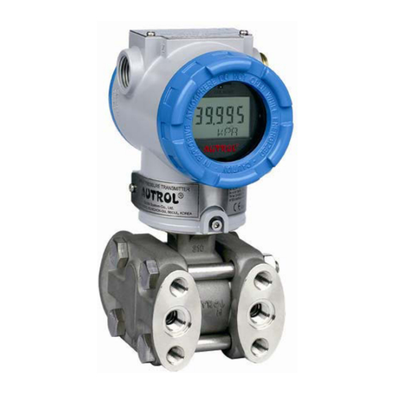
Внешний вид преобразователей приведен на рисунке 1.
мод. АРТ3100 мод. АРТ3200
Рисунок 1 — Внешний вид давления преобразователей давления AUTROL
Технические характеристики
Метрологические и технические характеристики приведены в таблице 1. Таблица 1
|
Наименование характеристики |
Значения характеристики |
|||
|
АРТ3100- G |
АРТ3100- D |
АРТ3100- Н |
АРТ3100- А |
|
|
Вид измеряемого давления |
избыточн. |
разность давлений |
абсолютн. |
|
|
Верхние пределы измерений (ВПИ), кПа |
от 1,5 до 41370 |
от 1,5 до 6895 |
от 37,3 до 2068 |
от 200 до 2500 |
|
Нижние пределы измерений, кПа |
0; минус 100 |
0 |
||
|
Пределы допускаемой основной приведенной погрешности, % от диапазона измерений |
± 0,04; ± 0,075; ±0,2 |
|||
|
Пределы доп. погрешности, вызванные изменением температуры нормальных условий окружающего воздуха до любой температуры в пределах значений рабочих температур на 10 °С, % от диапазона измерений |
±0,06 |
|||
|
Выходной сигнал — аналоговый, мА — цифровой |
от 4 до 20 НАRТ протокол |
|||
|
Напряжение питания постоянного тока, В — номинальное напряжение — допустимое рабочее напряжение |
24 от 11,9 до 45 |
|
Наименование характеристики |
Значения характеристики |
|||
|
АРТ3100- АРТ3100-G D |
АРТ3100- Н |
АРТ3100- А |
||
|
Потребляемая мощность, Вт, не более |
0,9 |
|||
|
Максимальное допускаемое испытательное давление, МПа |
(от 13,79 до 51,71)* |
— |
— |
(от 0,4 до 3)* |
|
Максимальное допустимое рабочее (статическое) давление, МПа |
— |
13,79 |
31,79 |
— |
|
Г абаритные размеры (длина х ширина х высота), мм, не более |
120x126x190,5 |
|||
|
Масса, кг не более |
4 |
|||
|
Наработка на отказ, ч |
100 000 |
|||
|
Средний срок службы, лет |
10 |
*- в зависимости от диапазона измерений.
Продолжение таблицы 1
|
Наименование характеристики |
Значения характеристики |
|
|
АРТ3200^ |
АРТ3200-А |
|
|
Вид измеряемого давления |
избыточное |
абсолютное |
|
Верхние пределы измерений (ВПИ), кПа |
от 150 до 60000 |
от 2 до 2500 |
|
Нижние пределы измерений, кПа |
0; минус 100 |
0 |
|
Пределы допускаемой основной приведенной погрешности, % от диапазона измерений |
± 0,04; ± 0,075; ±0,2 |
|
|
Пределы доп. погрешности, вызванные изменением температуры нормальных условий окружающего воздуха до любой температуры в пределах значений рабочих температур на 10 °С, % от диапазона измерений |
±0,06 |
|
|
Выходной сигнал — аналоговый, мА — цифровой |
от 4 до 20 HART протокол |
|
|
Напряжение питания постоянного тока, В — номинальное напряжение — допустимое рабочее напряжение |
24 от 11,9 до 45 |
|
|
Потребляемая мощность, Вт, не более |
0,9 |
|
|
Максимальное допускаемое испытательное давление, МПа |
(от 1,25 до 75)* |
(от 0,4 до 3)* |
|
Г абаритные размеры (длинахширинах хвысота), мм, не более |
172х127х155 |
|
|
Масса, кг не более |
2 |
|
|
Наработка на отказ, ч |
100 000 |
|
|
Средний срок службы, лет |
10 |
*- в зависимости от диапазона измерений.
Всего листов 5
Условия эксплуатации:
Диапазон рабочих температур окружающей среды, °С -для преобразователей с ЖКИ дисплеем -для преобразователей без ЖКИ дисплея Атмосферное давление окружающего воздуха, кПа Относительная влажность окружающего воздуха, %
от минус 30 до 80 от минус 40 до 85 от 84,0 до 106,7
до 100 до 98
-для преобразователей АРТ3100 -для преобразователей АРТ3200
Знак утверждения типа
Знак утверждения типа наносится типографским способом на титульный лист руководства по эксплуатации и методом наклейки или иным методом на корпус преобразователей.
Комплектность
Преобразователь — 1 шт.
Калибровочный сертификат изготовителя — 1 экз.
Руководство по эксплуатации — 1 экз.
Поверка
осуществляется по документу МИ 1997-89 «Рекомендация ГСИ. Преобразователи давления измерительные. Методика поверки».
Сведения о методах измерений
Сведения о методе измерений приведены в документе «Преобразователи давления AUTROL мод. АРТ3100, АРТ3200. Руководство по эксплуатации».
Нормативные и технические документы, устанавливающие требования к преобразователям давления AUTROL мод. АРТ3100, АРТ3200
1 ГОСТ 22520-85 «Датчики давления, разрежения и разности давлений с электрическими аналоговыми выходными сигналами ГСП»
2 ГОСТ 8.017-79 «ГСИ. Государственный первичный эталон и общесоюзная поверочная схема для средств измерений избыточного давления до 250 МПа»
3 ГОСТ 8.187-76 «ГСИ. Государственный специальный эталон и общесоюзная поверочная схема для средств измерений разности давлений до 4-104 Па».
4 ГОСТ 8.223-76 «ГСИ. Государственный специальный эталон и общесоюзная поверочная схема для средств измерений абсолютного давления в диапазоне 2,7-102-4000-102 Па»
5 МИ 1997-89 «Рекомендация ГСИ. Преобразователи давления измерительные. Методика поверки»
6 Техническая документация изготовителя.
Рекомендации к применению
выполнение работ по оценке соответствия промышленной продукции и продукции других видов, а также иных объектов установленным законодательством РФ обязательным требованиям, осуществление производственного контроля за соблюдением установленных законодательством Российской Федерации требований промышленной безопасности к эксплуатации опасного производственного объекта.
Заказать

Интеллектуальные датчики давления APT3100, APT3200, APT3500, APT3700
Микропроцессорные датчики давления серии APT3100, APT3200, APT3500, APT3700 предназначены, для преобразования входящих измеряемых величин в токовый или цифровой сигналы: абсолютного давления, избыточного давления, разности давлений, давленияразрежения и гидростатического давления (уровня). Широко применяются с 1989 года, в нефтегазовой, химической промышленности, энергетике, атомной промышленности и объектах морского кластера.
Работа и установка параметров датчиков, производится посредством:
• Клавиатуры LCD индикатора;
• HARTкоммуникатора;
• Программного обеспечения и средств АСУТП.
Преимущества датчика:
• Самодиагностика преобразователя, конвертера A/D с памятью, питания;
• Компактное исполнение;
• Устойчивость электроники к перегрузкам;
• Удобство установки «нуля» и настройки диапазона измерения;
• Гибкая калибровка по давлению и продукту;
• Конфигурация различных параметров датчика, посредством протокола HART.
Измеряемые среды: жидкости, в т.ч. нефтепродукты; пар и газ.
Функциональность и характеристики
• Легкое подключение датчика: DP, GP, AP, HP
• Диапазоны измеряемых давлений:
минимальный 0…0,075 кПа;
максимальный 0…41370кПа
• Выходные сигналы: аналоговый 420 мА и цифровой HARTпротокол;
• Высокая точность: от ±0,25% до ±0,075% во всем диапазоне измерений (Опция: ±0,04% со специальной калибровкой);
• Долгосрочная стабильность работы;
• Перенастройка диапазонов измерений в пределах 100:1;
• Конфигурация данных с помощью коммуникатора HART;
• Легкая регулировка нуля;
• Непрерывная самодиагностика датчика;
• Автоматическая компенсация от температуры окружающей среды;
• Защита от несанкционированной записи;
• Взрывобезопасное исполнение согласно стандартов: ГОСТ, ATEX и пр.;
• Морское свидетельство: ABS, LR, BR, DNV.
• Стандарты соответствия CE EMC (EN500812, EN500822)