Покраска дисков на WV R16 https://www.youtube.com/watch?v=aRcPbK_V-Wk&t=7s
покраска дисков ваз 2110 https://www.youtube.com/watch?v=W9oHoXtFlc0&t=16s
Реставрация составных дисков https://www.youtube.com/watch?v=Tqpqc9JHyBk
покраска дисков тойота королла https://www.youtube.com/watch?v=fw-CkbgbPBA&t=87s
покраска дисков на волгу https://www.youtube.com/watch?v=w2AUofRvgS0&t=14s
литые диски «Косей» https://www.youtube.com/watch?v=OF6pys1kjT8&t=1s
покраска дисков в 2 цвета и кэнди https://www.youtube.com/watch?v=NFPmdEZJSjM&t=1s
покраска дисков ниссан кашкай https://www.youtube.com/watch?v=u1NyE0T3gcY&t=1s
покраска дисков бмв е 39 https://www.youtube.com/watch?v=bHtPn213Pjk
Диски на мерседес сделаны под карбон https://www.youtube.com/watch?v=bBpuGC2Lyik&t=6s
литые диски красим в мокрый асфальт https://www.youtube.com/watch?v=G2TDlYcT7GU
покраска дисков в чёрный серый метал https://www.youtube.com/watch?
Видео правильный баланс на станке TS-500 канала MesserSmit79
Показать
- Manuals
- Brands
- Siemens Manuals
- Accessories
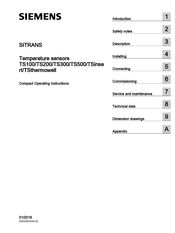
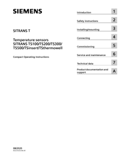
- SITRANS TS500
Manuals and User Guides for Siemens SITRANS TS500. We have 8 Siemens SITRANS TS500 manuals available for free PDF download: Compact Operating Instructions, Operating Instructions Manual
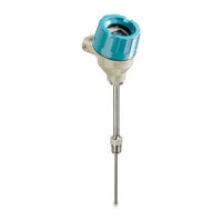
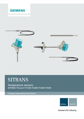
Siemens SITRANS TS500 Operating Instructions Manual (196 pages)
Brand: Siemens
|
Category: Temperature Controller
|
Size: 7.07 MB
Table of Contents
-
Table of Contents
3
-
1 Introduction
9
-
Purpose of this Documentation
9
-
Scope of Documentation
9
-
Functional Safety Manual
9
-
Document History
10
-
Product Compatibility TH320/420
10
-
Checking the Consignment
10
-
Security Information
11
-
Transportation and Storage
11
-
Notes on Warranty
12
-
-
2 Safety Notes
13
-
Preconditions for Use
13
-
Laws and Directives
13
-
Conformity with European Directives
14
-
Improper Device Modifications
14
-
Requirements for Special Applications
14
-
Use in Hazardous Areas
15
-
Use in Flameproof Enclosures «D» and Protection in Enclosures «Tb
15
-
For SITRANS TS500
16
-
Installation in «Flameproof Enclosures «D» and Enclosures «Tb
16
-
For SITRANS Tsinsert/Ts100/Ts200/Ts500
17
-
-
3 Description
19
-
Overview
19
-
Application
20
-
Functional Principles
20
-
Nameplate Structure
20
-
Temperature Transmitter for SITRANS TS500
21
-
Measuring Inserts for SITRANS TS500
22
-
Connection Heads for SITRANS TS500
23
-
USB Modem and SIPROM T
24
-
Applications
24
-
Product Features
24
-
Meaning of Leds on the USB Modem
25
-
-
4 Installing/Mounting
27
-
Basic Safety Notes
27
-
Installation and Location Requirements
28
-
Proper Mounting
29
-
Mounting the SITRANS TS500
31
-
Mounting SITRANS TS300 in Clamp-On Design
32
-
Rotating the Display
33
-
Disassembly
34
-
-
5 Connecting
35
-
Basic Safety Notes
35
-
For SITRANS Tsinsert
38
-
For SITRANS Tsinsert/Ts100/Ts200/Ts500
38
-
For SITRANS TS100/TS200
38
-
For SITRANS TS500
39
-
Connecting the Device
39
-
Connecting the Resistance Thermometer
39
-
Connecting the Thermocouple
40
-
Connecting the Plug-In Connector
41
-
Connecting the SITRANS TS500
42
-
Opening the Device
42
-
Connecting the SITRANS TS500 and TH320
43
-
Connecting the SITRANS TS500 and TH420
45
-
Closing the Device
48
-
Connecting TH320
49
-
Connecting TH420
50
-
-
6 Commissioning
53
-
Basic Safety Notes
53
-
Commissioning
54
-
Commissioning the USB Modem and SIPROM T
54
-
Fundamental Safety Instructions
54
-
Installing the SIPROM T Parameterization Software
55
-
Connecting USB Modem
57
-
-
7 Operating
59
-
Local Operation
59
-
Buttons
59
-
Operating the Device with Display
60
-
Navigating in the Views
60
-
Measurement View
61
-
Parameter View
62
-
Edit View
63
-
Remote Operation
65
-
Locking the Device
65
-
Introduction
65
-
Enable Write Protection with Write Protection Switch
65
-
Enable the User PIN on the Display
66
-
Enable the Button Lock on the Display
67
-
-
8 Parameter Assignment
69
-
Overview of Parameters and Functions
69
-
Parameters and Functions
69
-
Advanced Functions
72
-
Parameter Assignment with USB Modem and SIPROM T
73
-
Parameter Assignment over Device with Display
74
-
Input Type 1 [01]
74
-
Connection Type for Input 1 [02]
78
-
Wire Resistance for Connecting Cable at Input 1 [03]
78
-
Input Type 2 [04]
78
-
Connection Type for Input 2 [05]
81
-
Wire Resistance for Connecting Cable at Input 2 [06]
82
-
Assignment of the Primary Variable [07]
82
-
Introduction
82
-
Setting the Assignment of the Primary Variable
83
-
Unit [08]
83
-
Lower Range Value [09]/Upper Range Value [10]
84
-
Lower Range Value [09] Parameter
84
-
Upper Range Value [10] Parameter
84
-
Adjusting Lower Range Value/Upper Range Value
84
-
Damping Value [11]
85
-
Damping Value Parameter
85
-
Set Damping Value
85
-
Functional Safety [12]
86
-
Loop Test [13]
86
-
Loop Test with Preset Loop Current Value
86
-
Loop Test with User Defined Loop Current Value
87
-
One-Point Calibration Input 1 [14]
88
-
One-Point Calibration Input 2 [15]
88
-
Change User PIN [16]
88
-
Change User PIN
88
-
PIN Recovery [17]
89
-
Recovering the User PIN
90
-
User PIN [18]
91
-
User PIN
91
-
Enable User PIN
91
-
Disable User PIN
91
-
Minimum Measured Peak Value at Input 1 [19]
92
-
Maximum Measured Peak Value at Input 1 [20]
92
-
Minimum Measured Peak Value at Input 2 [21]
93
-
Maximum Measured Peak Value at Input 2 [22]
93
-
Minimum Transmitter Electronics Temperature [23]
93
-
Maximum Transmitter Electronics Temperature [24]
93
-
Button Lock [25]
93
-
Enabling Button Lock
94
-
Disabling Button Lock
94
-
Assigning Parameters Using Remote Operation
95
-
Introduction
95
-
Quick Start» Wizard
95
-
Identification
96
-
User-Specific Type
96
-
Introduction
96
-
Set the Linearization Table (60 Breakpoints)
98
-
Set the Spline Curve (40 Breakpoints)
98
-
Sensor Calibration
98
-
Introduction
98
-
Setting One-Point Calibration
99
-
Setting Two-Point Calibration
100
-
Transmitter Sensor Matching
101
-
Introduction
101
-
Changing the Callendar-Van Dusen Coefficients
102
-
Assignment of Dynamic Variables
102
-
Operating Hours Counter
102
-
Current Output
103
-
Fault Current
103
-
Lower Saturation Limit Parameter
104
-
Upper Saturation Limit Parameter
105
-
Setting the Fault Current of the Internal Transmitter with Switch to ≥ 21 Ma
106
-
-
9 Service and Maintenance
109
-
Basic Safety Notes
109
-
Maintenance
109
-
Sitrans Ts500
109
-
Cleaning
110
-
Maintenance and Repair Work
111
-
Uninstalling USB Drivers
112
-
Sitrans Ts500
113
-
Replacing the Display
114
-
Removing the Display
114
-
Installing the Display
115
-
Service and Maintenance
115
-
Return Procedure
116
-
Disposal
117
-
-
10 Diagnostics and Troubleshooting
119
-
Device Status Symbols
119
-
Diagnostic Messages
122
-
Troubleshooting of USB Modem
126
-
-
11 Technical Data
127
-
Rated Conditions
127
-
Minimum Permissible Ambient Temperatures in the Connection Area of the Sensor
127
-
Maximum Permissible Ambient Temperatures in the Connection Area of the Sensor
128
-
General Limitations for Compression Fittings
128
-
Sitrans Ts100
128
-
Sitrans Ts500
129
-
Maximum Permitted Sample Temperatures Within the Process
138
-
Measuring Range
139
-
Construction
140
-
Electrical Data
141
-
Measuring Tolerances for Resistance Thermometers
142
-
Measuring Accuracy for Thermocouples
142
-
Certificates and Approvals
144
-
SITRANS Tsinsert/Ts100/Ts200/Ts500
144
-
Sitrans Ts500
145
-
Display
146
-
Factory Settings of SITRANS TH320/TH420
147
-
Factory Setting of SITRANS TH320
147
-
Factory Setting of SITRANS TH420
147
-
-
12 Dimension Drawings
149
-
Overview
149
-
Sitrans Ts100
153
-
Sitrans Ts200
154
-
Sitrans Ts300
155
-
Sitrans Ts500
159
-
SITRANS TS500, Types 2 and 2N
159
-
SITRANS TS500, Types 2G and 2F
160
-
SITRANS TS500, Type 3
161
-
SITRANS TS500, Types 3G and 3F
162
-
SITRANS TS500, Types 4 and 4F
163
-
SITRANS TS500, Type ST, Threaded Tapered Well (7MC65
164
-
SITRANS TS500, Type SST, Threaded Tapered Well (7MC55
166
-
SITRANS TS500, Type SS, Threaded Straight Well (7MC65
167
-
SITRANS TS500, Type SS, Threaded Straight Well (7MC55
169
-
SITRANS TS500, Type SR, Threaded Reduced Well (7MC65
170
-
SITRANS TS500, Type SR, Threaded Reduced Well (7MC55
171
-
SITRANS TS500, Type FT, Flanged Tapered Well (7MC65
172
-
SITRANS TS500, Type FST, Flanged Tapered Well (7MC55
173
-
SITRANS TS500, Type FS, Flanged Straight Well (7MC65
175
-
SITRANS TS500, Type FS, Flanged Straight Well (7MC55
176
-
SITRANS TS500, Type FR, Flanged Reduced Well (7MC65
177
-
SITRANS TS500, Type FR, Flanged Reduced Well (7MC55
178
-
SITRANS TS500, Type SWT, Socket Tapered Well (7MC65
179
-
SITRANS TS500, Type SWST, Socket Tapered Well (7MC55
180
-
SITRANS TS500, Type SWS, Socket Straight Well (7MC65
181
-
SITRANS TS500, Type SWS, Socket Straight Well (7MC55
182
-
SITRANS TS500, Type SWR, Socket Reduced Well (7MC65
183
-
SITRANS TS500, Type SWR, Socket Reduced Well (7MC55
184
-
SITRANS TS500 for Installation in Existing Protective Tubes
185
-
SITRANS TS500, Type GP, General Purpose, no Well
187
-
SITRANS Tsinsert — Measuring Inserts for SITRANS TS500
188
-
-
Product Documentation and Support
189
-
Product Documentation
189
-
Technical Support
190
-
QR Code Label
190
-
-
Remote Operation
191
-
Simatic Pdm
191
-
Overview SIMATIC PDM
191
-
Check SIMATIC PDM Version
191
-
Updating the Electronic Device Description (EDD)
192
-
-
Index
193
Advertisement
Siemens SITRANS TS500 Compact Operating Instructions (392 pages)
Brand: Siemens
|
Category: Temperature Controller
|
Size: 9.19 MB
Siemens SITRANS TS500 Compact Operating Instructions (245 pages)
Temperature sensors
Brand: Siemens
|
Category: Accessories
|
Size: 9.66 MB
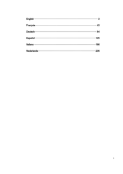
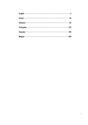
Table of Contents
-
Safety Information
5
-
Electrical Connection
17
-
Technical Data
22
-
Electrical Data
25
-
Mise en Service
59
-
Entretien Et Maintenance
60
-
Technische Daten
103
-
Dati Tecnici
185
-
Technische Gegevens
225
Advertisement
Siemens SITRANS TS500 Compact Operating Instructions (245 pages)
Brand: Siemens
|
Category: Temperature Controller
|
Size: 9.97 MB
Siemens SITRANS TS500 Compact Operating Instructions (244 pages)
Brand: Siemens
|
Category: Temperature Controller
|
Size: 9.97 MB
Siemens SITRANS TS500 Compact Operating Instructions (245 pages)
Brand: Siemens
|
Category: Temperature Controller
|
Size: 9.91 MB
Siemens SITRANS TS500 Compact Operating Instructions (110 pages)
Temperature sensors
Brand: Siemens
|
Category: Accessories
|
Size: 4.42 MB
Table of Contents
-
Table of Contents
3
-
1 Introduction
7
-
Purpose of this Documentation
7
-
Scope of this Documentation
7
-
Document History
8
-
Checking the Consignment
8
-
Security Information
9
-
Transportation and Storage
9
-
Notes on Warranty
10
-
-
2 Safety Notes
11
-
Preconditions for Use
11
-
Laws and Directives
11
-
Conformity with European Directives
12
-
Improper Device Modifications
12
-
Requirements for Special Applications
13
-
Use in Hazardous Areas
13
-
Qualified Personnel for Hazardous Area Applications
13
-
Use in Flameproof Enclosures «D» and Protection in Enclosures «Tb
14
-
For SITRANS TS500
15
-
For SITRANS Tsinsert/Ts100/Ts200/Ts500
16
-
-
3 Description
17
-
Overview
17
-
Application
18
-
Functional Principles
18
-
Nameplate Structure
18
-
Temperature Transmitter for SITRANS TS500
19
-
Measuring Inserts for SITRANS TS500
20
-
Connection Heads for SITRANS TS500
21
-
-
4 Installing
23
-
Basic Safety Notes
23
-
Installation and Location Requirements
24
-
Proper Mounting
25
-
Install
27
-
Install SITRANS TS300 Clamp-On
29
-
Disassembly
30
-
-
5 Connecting
31
-
Basic Safety Notes
31
-
For SITRANS Tsinsert
34
-
For SITRANS Tsinsert/Ts100/Ts200/Ts500
34
-
For SITRANS TS100/TS200
34
-
For SITRANS TS500
35
-
Electrical Connection
35
-
Electrical Connection of Resistance Thermometers
36
-
Electrical Connection of Thermocouples
37
-
Electrical Connection of Connectors
37
-
-
6 Commissioning
39
-
Basic Safety Notes
39
-
Commissioning
40
-
-
7 Service and Maintenance
41
-
Cleaning
43
-
Return Procedure
43
-
Disposal
44
-
-
8 Technical Data
45
-
Rated Conditions
45
-
Maximum Permissible Ambient Temperatures in the Connection Area of the Sensor
45
-
General Limitations for Compression Fittings
45
-
Sitrans Ts100
46
-
Sitrans Ts500
47
-
Maximum Permitted Sample Temperatures Within the Process
54
-
Measuring Range
56
-
Construction
56
-
Electrical Data
57
-
Measuring Tolerances for Resistance Thermometers
58
-
Measuring Accuracy for Thermocouples
59
-
Certificates and Approvals
60
-
SITRANS Tsinsert/Ts100/Ts200/Ts500
60
-
Sitrans Ts500
62
-
-
9 Dimension Drawings
65
-
Overview
65
-
Sitrans Ts100
69
-
Sitrans Ts200
70
-
Sitrans Ts300
71
-
9.5 Sitrans Ts500
75
-
SITRANS TS500, Types 2 and 2N
75
-
SITRANS TS500, Types 2G and 2F
76
-
SITRANS TS500, Type 3
77
-
SITRANS TS500, Types 3G and 3F
78
-
SITRANS TS500, Types 4 and 4F
79
-
SITRANS TS500, Type ST, Threaded Tapered Well (7MC65
81
-
SITRANS TS500, Type SST, Threaded Tapered Well (7MC55
82
-
SITRANS TS500, Type SS, Threaded Straight Well (7MC65
84
-
SITRANS TS500, Type SS, Threaded Straight Well (7MC55
85
-
SITRANS TS500, Type SR, Threaded Reduced Well (7MC65
86
-
SITRANS TS500, Type SR, Threaded Reduced Well (7MC55
87
-
SITRANS TS500, Type FT, Flanged Tapered Well (7MC65
88
-
SITRANS TS500, Type FST, Flanged Tapered Well (7MC55
89
-
SITRANS TS500, Type FS, Flanged Straight Well (7MC65
91
-
SITRANS TS500, Type FS, Flanged Straight Well (7MC55
92
-
SITRANS TS500, Type FR, Flanged Reduced Well (7MC65
93
-
SITRANS TS500, Type FR, Flanged Reduced Well (7MC55
94
-
SITRANS TS500, Type SWT, Socket Tapered Well (7MC65
95
-
SITRANS TS500, Type SWST, Socket Tapered Well (7MC55
96
-
SITRANS TS500, Type SWS, Socket Straight Well (7MC65
98
-
SITRANS TS500, Type SWS, Socket Straight Well (7MC55
99
-
SITRANS TS500, Type SWR, Socket Reduced Well (7MC65
100
-
SITRANS TS500, Type SWR, Socket Reduced Well (7MC55
101
-
SITRANS TS500 for Installation in Existing Protective Tubes
102
-
SITRANS TS500, Type GP, General Purpose, no Well
104
-
SITRANS Tsinsert — Measuring Inserts for SITRANS TS500
105
-
-
Appendix
107
-
Certificates
107
-
Technical Support
107
-
A.1 Certificates
107
-
Index
109
-
Siemens SITRANS TS500 Compact Operating Instructions (60 pages)
Brand: Siemens
|
Category: Temperature Controller
|
Size: 1.33 MB
Table of Contents
-
Table of Contents
3
-
1 Introduction
5
-
Purpose of this Documentation
5
-
Scope of Documentation
5
-
Document History
5
-
Intended Use
5
-
Checking the Consignment
6
-
Security Information
6
-
Transportation and Storage
7
-
Notes on Warranty
7
-
-
2 Safety Instructions
9
-
Preconditions for Use
9
-
Laws and Directives
9
-
Conformity with European Directives
10
-
Improper Device Modifications
10
-
Requirements for Special Applications
10
-
Use in Hazardous Areas
11
-
Use in Flameproof Enclosures «D» and Protection in Enclosures «Tb
11
-
For SITRANS TS500
12
-
Installation in «Flameproof Enclosures «D» and Enclosures «Tb
12
-
For SITRANS Tsinsert/Ts100/Ts200/Ts500
13
-
-
3 Installing/Mounting
15
-
Basic Safety Notes
15
-
Installation and Location Requirements
16
-
Proper Mounting
17
-
Mounting the SITRANS TS500
19
-
Mounting SITRANS TS300 in Clamp-On Design
20
-
Disassembly
21
-
-
4 Connecting
23
-
Basic Safety Notes
23
-
For SITRANS Tsinsert
26
-
For SITRANS Tsinsert/Ts100/Ts200/Ts500
26
-
For SITRANS TS100/TS200
26
-
For SITRANS TS500
27
-
Connecting the Device
27
-
Connecting the Resistance Thermometer
27
-
Connecting the Thermocouple
28
-
Connecting the Plug-In Connector
29
-
-
5 Commissioning
31
-
Basic Safety Notes
31
-
Commissioning
32
-
-
6 Service and Maintenance
33
-
Basic Safety Notes
33
-
Maintenance
33
-
Sitrans Ts500
33
-
Cleaning
34
-
Maintenance and Repair Work
35
-
Sitrans Ts500
36
-
Service and Maintenance
36
-
Return Procedure
37
-
Disposal
38
-
-
7 Technical Data
39
-
Rated Conditions
39
-
Minimum Permissible Ambient Temperatures in the Connection Area of the Sensor
39
-
Maximum Permissible Ambient Temperatures in the Connection Area of the Sensor
40
-
General Limitations for Compression Fittings
40
-
Sitrans Ts100
40
-
Sitrans Ts500
41
-
Maximum Permitted Sample Temperatures Within the Process
50
-
Measuring Range
51
-
Construction
52
-
Electrical Data
53
-
Certificates and Approvals
53
-
SITRANS Tsinsert/Ts100/Ts200/Ts500
54
-
Sitrans Ts500
54
-
-
Product Documentation and Support
57
-
Product Documentation
57
-
Technical Support
58
-
QR Code Label
58
-
-
Index
59
Advertisement
Related Products
-
Siemens TC12
-
Siemens TC63
-
Siemens SITRANS TS100
-
Siemens SITRANS TS200
-
Siemens SITRANS TS300
-
Siemens sitrans
-
Siemens SITRANS WFS320
-
Siemens SITRANS AS100
-
Siemens SITRANS WS300
-
Siemens SITRANS FSS200
Siemens Categories
Controller
Control Unit
Industrial Equipment
![]()
Washer
![]()
Switch
More Siemens Manuals
48,001.0 руб.
TS500 Балансировочный стенд
- Масса колеса до — 65 кг
- Диаметр колеса до — 760 мм
- Диаметр диска 10–21”
- Ширина диска 3–9”
- Питание от сети — 220В
- Потребление — 0,2 кВт
- Точность балансировки до — 1 гр
- Время измерения — 8 сек
- Опорный вал — 36 мм
Упаковка
- Масса — 115
- Габариты — 120 / 80 / 90 см
-
Описание
-
Отзывы (0)
Описание
TS-500 Балансировочный станок — это стенд для компьютерный балансировки колёс легковых автомобилей с ручным вводом параметров колеса.
Особенности
- Динамическая и статическая балансировка.
- Прогрессивная технология измерений позволяет произвести все вычисления за один рабочий цикл даже в том случае, когда грузики на разных плоскостях потребуется установить близко друг от друга.
- Режимы работы DINAMIC, STATIC, ALU1, ALU2, ALU3.
- Режим автокалибровки.
- Кожух с возможностью подключения автозапуска в комплекте.
Комплектация
- Конус 1 (135-90мм)
- Конус 2 (106-75мм)
- Конус 3 (77-55мм)
- Конус 4 (61-41мм)
- Кронциркуль – 1шт.
- Защитный кожух – 1шт.
- Клещи для установки/снятия грузов – 1шт.
- Грузик 100 грамм для калибровки станка – 1шт.
- Инструкция по эксплуатации – 1шт.
Характеристики TS 500
- Масса колеса до — 65 кг
- Диаметр колеса до — 760 мм
- Диаметр диска 10–21”
- Ширина диска 3–9”
- Питание от сети — 220В
- Потребление — 0,2 кВт
- Точность балансировки до — 1 гр
- Время измерения — 8 сек
- Опорный вал — 36 мм
Упаковка
- Масса — 115
- Габариты — 120 / 80 / 90 см


TS-500 Балансировочный станок купить
Только зарегистрированные клиенты, купившие данный товар, могут публиковать отзывы.