- Manuals
- Brands
- Can-Am Manuals
- Offroad Vehicle
- 2008 DS 450
- Operator’s manual
-
Contents
-
Table of Contents
-
Troubleshooting
-
Bookmarks
Quick Links
Related Manuals for Can-Am 2008 DS 450
Summary of Contents for Can-Am 2008 DS 450
-
Page 2
WARNING YOUR VEHICLE CAN BE HAZARDOUS TO OPERATE. A collision or rollover can occur quickly, even during routine maneuvers such as turning and driv- ing on hills or over obstacles, if you fail to take proper precautions. For your safety, understand and follow all the warnings contained in this Operator’s Guide and the labels on your vehicle. -
Page 3: Important Information
In Canada, products are distributed by Bombardier Recreational Products Inc. (BRP). In USA, products are distributed by BRP US Inc. The following trademarks are the property of Bombardier Recreational Prod- ucts Inc.: Can-Am™ DS 450 Rotax ® XP-S…
-
Page 4
FOREWORD Congratulations on your purchase of a The information and components/ new Can-Am™ ATV. It is backed by the system descriptions contained in this BRP warranty and a network of autho- document are correct at the time of rized Can-Am dealers ready to provide publication. -
Page 5: Table Of Contents
TABLE OF CONTENTS While reading this Operator’s Guide, remember that: WARNING Indicates a potential hazard that, if not avoided, could result in serious in- jury or death. NOTICE…………….7 INTRODUCTION ..
-
Page 6
2) Front Brake Lever …………64 3) Clutch Lever . -
Page 7
MAINTENANCE INFORMATION GENERAL …………….100 MAINTENANCE CHART . -
Page 8
WARRANTY BRP LIMITED WARRANTY NORTH AMERICA: 2008 CAN-AM ATV . .. 130 BRP INTERNATIONAL LIMITED WARRANTY: 2008 CAN-AM ATV ..134 BRP EUROPEAN UNION MEMBER STATES LIMITED WARRANTY: 2008 CAN-AM ATVS …………..138 PRIVACY OBLIGATION/DISCLAIMER . -
Page 9: Notice
NOTICE This Operator’s Guide has been pre- pared to acquaint the owner/operator of a new vehicle with the various ve- hicle controls, maintenance and safe operating instructions. It is indispens- able for the proper use of the product. This Operator’s Guide uses the follow- ing symbols.
-
Page 10: Introduction
INTRODUCTION Your dealer should have provided you The contents of this Operator’s Guide with some basic information on the provide riding information which has particular controls and features of your been proven reliable by other users. new vehicle. Please take the time to They are not intended as a definitive study this Operator’s Guide and all means of avoiding accidents.
-
Page 11: Safety Information
SAFETY INFORMATION ____________ ____________ SAFETY INFORMATION…
-
Page 12: Special Safety Messages
Operator’s Guide. instructor. Contact an authorized Always keep both hands on the Can-Am for more informations. handlebars and both feet on the USA and Canada only: to find footrests of the vehicle during op- out about available training course eration.
-
Page 13
Never operate this vehicle on hills Always use proper procedures if too steep for the vehicle or for your you stall or roll backwards when abilities. Practice on smaller hills climbing a hill. To avoid stalling, before attempting larger hills. use proper gear and maintain a steady speed when climbing a hill. -
Page 14
Allow greater distance for braking. MORE INFORMATION ABOUT ATV SAFETY, contact an authorized Can-Am dealer to find out about available training courses nearest you. USA and Canada only: Call the Specialty Vehicle Institute of Amer-… -
Page 15: Operation Warnings
Beginning and inexperienced operators should complete a training course. They should then regularly practice the skills learned in the course and the operating techniques described in this Operator’s Guide. For more information about the training course, contact an authorized Can-Am dealer. ____________ ___________ SAFETY INFORMATION…
-
Page 16
WARNING POTENTIAL HAZARD Failure to follow the age recommendations for this vehicle. WHAT CAN HAPPEN A lack of respect for this age recommendation can lead to severe injury or death of the child. Even though a child may be within the age group for which this vehicle is recommended, he may not have the skills, abilities, or judgment needed to operate this vehicle safely and may be involved in a serious accident. -
Page 17
WARNING POTENTIAL HAZARD Carrying a passenger on this vehicle. WHAT CAN HAPPEN Greatly reduces your ability to balance and control this vehicle. Could cause an accident, resulting in harm to you and/or your passenger. HOW TO AVOID THE HAZARD Never carry a passenger. Even with a long seat that provides unrestricted operator movement, it is not designed nor intended to carry passenger(s). -
Page 18
WARNING POTENTIAL HAZARD Operating this vehicle on paved surfaces. WHAT CAN HAPPEN The tires are designed for off-road use only, not for use on pavement. Paved surfaces may seriously affect handling and control of this vehicle, and may cause the vehicle to go out of control. HOW TO AVOID THE HAZARD Never operate this vehicle on any paved surfaces, including sidewalks, driveways, parking lots and streets. -
Page 19
WARNING POTENTIAL HAZARD Operating this vehicle on public streets, roads or highways. WHAT CAN HAPPEN You can collide with another vehicle. HOW TO AVOID THE HAZARD Never operate this vehicle on any public street, road or highway, even a dirt or gravel one. In many states or provinces it is illegal to operate this vehicle on public streets, roads or highways. -
Page 20
WARNING POTENTIAL HAZARD Riding this vehicle without wearing an approved helmet, eye protection and protective clothing. WHAT CAN HAPPEN The following items concern all ATV’s operator: – Riding without an approved helmet increases the chances of a se- vere head injury or death in the event of an accident. –… -
Page 21
WARNING POTENTIAL HAZARD Riding this vehicle after consuming alcohol or drugs. WHAT CAN HAPPEN Could seriously affect your judgment. Could cause you to react more slowly. Could affect your balance and perception. Could result in an accident or death. HOW TO AVOID THE HAZARD Never consume alcohol or drugs before or while riding this vehicle. -
Page 22
WARNING POTENTIAL HAZARD Operating this vehicle at excessive speeds. WHAT CAN HAPPEN Increases your chances of losing control of the vehicle, which can result in an accident. HOW TO AVOID THE HAZARD Always travel at a speed which is proper for the terrain, visibility and op- erating conditions, and your experience. -
Page 23
WARNING POTENTIAL HAZARD Attempting wheelies, jumps and other stunts. WHAT CAN HAPPEN Increases the chance of an accident, including an overturn. HOW TO AVOID THE HAZARD Never attempt stunts, such as wheelies or jumps. Do not try to show off. ____________ ___________ SAFETY INFORMATION… -
Page 24
WARNING POTENTIAL HAZARD Failure to inspect the vehicle before operating. Failure to properly maintain the vehicle. WHAT CAN HAPPEN Increases the possibility of an accident or equipment damage. HOW TO AVOID THE HAZARD Always inspect your vehicle each time you use it to make sure the vehicle is in safe operating condition. -
Page 25
WARNING POTENTIAL HAZARD Removing hands from handlebar or feet from the footrests during opera- tion. WHAT CAN HAPPEN Removing even one hand or foot can reduce your ability to control the vehicle or could cause you to lose your balance and fall off the vehicle. If you remove a foot from the footrests, your foot or leg may come into contact with the rear wheels, which could injure you or cause an accident. -
Page 26
WARNING POTENTIAL HAZARD Failure to use extra care when operating this vehicle on unfamiliar terrain. WHAT CAN HAPPEN You can come upon hidden rocks, bumps, or holes, without enough time to react. Could result in the vehicle overturning or loss of control. HOW TO AVOID THE HAZARD Go slowly and be extra careful when operating on unfamiliar terrain. -
Page 27
WARNING POTENTIAL HAZARD Failure to use extra care when operating on excessively rough, slippery or loose terrain. WHAT CAN HAPPEN Could cause loss of traction or vehicle control, which could result in an accident, including an overturn. HOW TO AVOID THE HAZARD Do not operate on excessively rough, slippery or loose terrain until you have learned and practiced the skills necessary to control this vehicle on such terrain. -
Page 28
WARNING POTENTIAL HAZARD Turning improperly. WHAT CAN HAPPEN Vehicle could go out of control, causing a collision or overturn. HOW TO AVOID THE HAZARD Always follow proper procedures for turning as described further in this Operator’s Guide. Practice turning at low speeds before attempting to turn at faster speeds. -
Page 29
WARNING POTENTIAL HAZARD Operating on excessively steep hills. WHAT CAN HAPPEN The vehicle can overturn more easily on extremely steep hills than on level surfaces or small hills. HOW TO AVOID THE HAZARD Never operate this vehicle on hills too steep for the vehicle or for your abil- ities. -
Page 30
WARNING POTENTIAL HAZARD Climbing hills improperly. WHAT CAN HAPPEN Could cause loss of control or cause vehicle to overturn. HOW TO AVOID THE HAZARD Always follow proper procedures for climbing hills as described further in this Operator’s Guide. Always check the terrain carefully before you start up any hill. Never climb hills with excessively slippery or loose surfaces. -
Page 31
WARNING POTENTIAL HAZARD Going down a hill improperly. WHAT CAN HAPPEN Could cause loss of control or cause vehicle to overturn. HOW TO AVOID THE HAZARD Always follow proper procedures for going down hills as described further in this Operator’s Guide. NOTE: A special technique is required when braking as you go down a hill. -
Page 32
WARNING POTENTIAL HAZARD Improperly crossing hills or turning on hills. WHAT CAN HAPPEN Could cause loss of control or cause vehicle to overturn. HOW TO AVOID THE HAZARD Never attempt to turn the vehicle around on any hill until you have mas- tered the turning technique as described further in this Operator’s Guide on level ground. -
Page 33
WARNING POTENTIAL HAZARD Stalling, rolling backwards or improperly dismounting while climbing a hill. WHAT CAN HAPPEN Could result in vehicle overturning. HOW TO AVOID THE HAZARD Use proper gear and maintain steady speed when climbing a hill. If you lose all forward speed: Keep your weight uphill. -
Page 34
WARNING POTENTIAL HAZARD Improperly operating over obstacles. WHAT CAN HAPPEN Could cause loss of control or a collision. Could cause the vehicle to overturn. HOW TO AVOID THE HAZARD Before operating in a new area, check for obstacles. Never attempt to ride over large obstacles, such as large rocks or fallen trees. -
Page 35
WARNING POTENTIAL HAZARD Skidding or sliding improperly. WHAT CAN HAPPEN You may lose control of this vehicle. You may also regain traction unexpectedly, which may cause the vehicle to overturn. HOW TO AVOID THE HAZARD Learn to safely control skidding or sliding by practicing at low speeds and on level smooth terrain. -
Page 36
WARNING POTENTIAL HAZARD Operating this vehicle through deep or fast flowing water. WHAT CAN HAPPEN Tires may float, causing loss of traction and loss of control, which could lead to an accident. HOW TO AVOID THE HAZARD Never operate this vehicle in fast flowing water or in water deeper than that specified further in this Operator’s Guide. -
Page 37
WARNING POTENTIAL HAZARD Operating this vehicle with improper tires, or with improper or uneven tire pressure. WHAT CAN HAPPEN Use of improper tires on this vehicle, or operation of this vehicle with im- proper or uneven tire pressure, may cause loss of control, tire blow outs, tire to move around on its rim, and increases the risk of an accident. -
Page 38
All parts and accessories added to this vehicle should be approved by BRP and should be installed and used according to instructions. If you have questions, consult an authorized Can-Am dealer. Modification of the vehicle to increase speed and performance may violate the terms and conditions of your vehicle limited warranty. -
Page 39
WARNING POTENTIAL HAZARD Overloading this vehicle or carrying or towing cargo improperly. WHAT CAN HAPPEN Could cause changes in vehicle handling which could lead to an accident. HOW TO AVOID THE HAZARD Never exceed the stated load capacity for this vehicle including operator as well as other loads and added accessories. -
Page 40
WARNING POTENTIAL HAZARD Transporting flammable or dangerous material can lead to explosions. WHAT CAN HAPPEN This can cause serious injury or death. HOW TO AVOID THE HAZARD Never transport flammable or dangerous material. While reading this Operator’s Guide, remember that: WARNING Indicates a potential hazard that, if not avoided, could result in serious in- jury or death. -
Page 41: Riding The Vehicle
Never assume that vehicle thorized Can-Am dealer. will go everywhere safely. Sudden USA and Canada only: to find out changes in terrain caused by holes, about available training course nearest depressions, banks, softer or harder you, call the Specialty Vehicle Institute “ground”…
-
Page 42
Correct any problem you may have sure they work properly. found before riding. See an autho- rized Can-Am dealer as necessary. – Verify if steering operates freely. – Activate throttle control lever sever- al times to ensure it operates freely. -
Page 43: Clothing
Clothing Actual weather conditions should help you decide how to dress. However, it is important that the operator always wear the appropriate protective clothing and apparel, including an approved helmet, eye protection, boots, gloves, long sleeved shirt and pants. This type of clothing will provide you protection from some of the minor hazards you may encounter en route.
-
Page 44: Carrying Loads
Carrying Loads Any load carried on the vehicle will affect the stability and control of the vehi- cle. For this reason, do not exceed the load limits of the vehicle’s manufacturer. Always make sure the load is secured and cannot interfere with your proper con- trol.
-
Page 45: Design Limitation
Observe the rule… “what you take in, carry out”. Do not litter. Do not start campfires unless you have permission to do so… and then only… away from dry areas. The hazards you may create on the trail may cause injury to others or yourself, even at a later date.
-
Page 46: Uphill Driving
Uphill Driving Due to configuration, this vehicle has excellent climbing ability, so much so that tipover is possible before traction is lost. For example, its common to encounter terrain situations where the top of the hill has eroded to a point that the hill peak rises very sharply.
-
Page 47
To maintain proper control it is strongly advised that you keep your hands on the handlebar and within easy reach of all controls. The same holds true for your feet. To minimize the possibility of any leg or foot injury, keep your feet on the footrests at all times. -
Page 48
Water will affect the braking ability of your vehicle. Make sure you dry the brakes by applying them several times after the vehicle leaves the water. Mud or marsh lands may be encountered near water. Be prepared for sudden “holes” or changes in depth. Similarly so, be watchful of hazards such as rocks, logs, etc., partially covered by vegetation. -
Page 49
When riding in sand dunes it is advisable to equip the vehicle with an antenna type safety flag. This will help make your location more visible to others over the next sand dune. Proceed carefully should you see another safety flag ahead. Since the antenna type safety flag can snag and rebound on your body if caught, do not use it in areas where there are low hanging branches or obstacles. -
Page 50
When stopped or parked always apply the parking device. This is especially im- portant when parking on a slope. On very steep inclines or if the ATV is carring a cargo, the wheels should be blocked using rocks or bricks. Uphill Keep your body weight forward towards the top of the hill. -
Page 51
Downhill Keep your body weight rearwards. Apply the brake gradually to prevent skidding. Do not “coast” down the slope using solely engine compression or in neutral gear. ____________ ___________ SAFETY INFORMATION… -
Page 52
Side Hilling This is one of the most risky types of riding since it may drastically change the balance of the vehicle. It should be avoided wherever possible. If it is necessary to do so however, it is important that you ALWAYS keep your body weight on the upside of the slope… -
Page 53: Routine Maintenance
Part of your responsibility towards safety is to respect the contents of this Op- erator’s Guide. It provides valuable advice on how to properly take care of your vehicle. If further assistance is required your authorized Can-Am dealer is always willing to help.
-
Page 54: Hang Tag
HANG TAG This vehicle comes with a hang tag and labels containing important safety infor- mation. Any person who rides this vehicle should read and understand this information before riding. vmo2006-005-009_en ___________ ___________ SAFETY INFORMATION…
-
Page 55: Important On Product Labels
If missing or damaged, they can be replaced free of charge. See an au- thorized Can-Am dealer. NOTE: The following illustrations used in this Operator’s Guide are a general representation only. Your model may differ.
-
Page 56
USA and Canada Models Label 3 Label 1 Label 4 vmo2008-011-088_en Label 5 Label 2 Label 6 vmo2008-011-089_en ___________ ___________ SAFETY INFORMATION… -
Page 57
Label 7 vmo2007-002-002 NOT SHOWN Other Countries in the World Label 8 vmo2008-011-090 While reading this Operator’s Guide, remember that: WARNING Indicates a potential hazard that, if not avoided, could result in serious in- jury or death. ____________ ___________ SAFETY INFORMATION… -
Page 58
___________ ___________ SAFETY INFORMATION… -
Page 59: Vehicle Information
VEHICLE INFORMATION _____________________…
-
Page 60: How To Identify Your Vehicle
These numbers are required by the authorized Can-Am dealer to complete warranty claims properly. No warranty will be allowed by BRP if the engine identification…
-
Page 61: Noise Emission Control System Regulation
NOISE EMISSION CONTROL SYSTEM REGULATION USA and Canada Only Tampering with Noise Control System is Prohibited! U.S. Federal law and Canadian provincial laws may prohibit the following acts or the causing there of: 1. The removal or rendering inoperative by any person other than for purposes of maintenance, repair or replacement of any device or element of design incorporated into any new vehicle for the purpose of noise control prior to its sale or delivery to the ultimate purchaser or while it is in use or,…
-
Page 62: Emission Requirements
EMISSION REQUIREMENTS USA Only The California Air Resources Board (CARB) requires that your vehicle complies with applicable exhaust emissions standards during its useful life, when operated and maintained according to the instructions supplied. A non-compliance RED label (as well as a GREEN label) is obtained annually dur- ing California Vehicle registration.
-
Page 63: Break-In Period
5-Hour Engine Oil and Filter Replacement The Can-Am DS 450/X is the most ad- vanced sport ATV and it has been de- signed using the latest technology all the way down to its synthetic multi- layer oil filter and break-in oil.
-
Page 64: Controls/Components/Instrument
CONTROLS/COMPONENTS/INSTRUMENT NOTE: Some controls/instruments/equipment are optional. vmo2008-011-096_a TYPICAL ______________________…
-
Page 65
vmo2008-011-097_a TYPICAL While reading this Operator’s Guide, remember that: WARNING Indicates a potential hazard that, if not avoided, could result in serious in- jury or death. _____________________… -
Page 66: Throttle Lever
WARNING WARNING This vehicle may exceed the per- Always release the throttle when formance of other vehicles you shifting gears. Shifting gears may have ridden in the past. without releasing the throttle, This category S (sport) is a high could cause loss of control in- performance vehicle for off road cluding the vehicle to overturn use only.
-
Page 67: Clutch Lever
4) Parking Brake When applied, it temporarily prevents the vehicle from moving. Useful when the brake needs to be locked for example such as doing a K-turn, dur- ing transportation or when the vehicle is not in operation. vmo2008-011-003_a 1. Adjustment cam 2.
-
Page 68: Multi-Switch Housing
vmo2008-011-005_b Step 1: Squeeze front brake lever and maintain Step 2: Move parking brake lever to desired position NOTE: Parking brake can be adjusted vmo2008-011-007_a in four (4) different positions. 1. Headlamp switch 2. Engine stop switch 3. Engine start button Headlamp Switch vmo2008-011-006_a PARKING BRAKE POSITIONS…
-
Page 69: Fuel Tank Cap
vmo2008-011-027_a vmo2008-011-009_b IGNITION SWITCH POSITIONS 1. Engine start button 1. OFF 2. ON “with light” 6) Fuel Tank Cap 3. ON “without light” CAUTION: Never place anything Engine Stop Switch over fuel tank cap because the vent This switch is used to stop engine and hole on the top of fuel tank cap can as an emergency control.
-
Page 70: Ignition Switch
7) Ignition Switch Can-Am dealer. Lamp blinks: Engine is under Key-operated 3 position switch. a protection mode (limp home), contact an authorized Can-Am dealer. fuel level. There approximately 2.5 L (0.6 U.S. gal) of fuel left in fuel tank.
-
Page 71: Gearshift Pedal
The tool kit contains tools for basic maintenance. The tools included in the tool kit are: – pliers (1) – screwdriver (1) – open wrench 10/13 mm (1) – socket wrench 16/18 mm (1) vmo2008-011-010_a 1. Front brake fluid reservoir –…
-
Page 72: Footpeg
Seat Installation Insert seat front upper slot into coolant tank hook, then make sure seat middle tab is well engaged. When seat rests in its position, firmly push seat down to latch. NOTE: A distinctive snap will be felt. Double check that the seat is secure by giving it a tug to confirm proper vmo2008-011-011_b latching.
-
Page 73: Engine Oil Tank Cap
vmo2008-011-061_a 1. Coolant tank cap location vmo2008-011-013_a 1. Rear brake fluid reservoir Refer to LIQUIDS section to check brake fluid level correctly. 16) Engine Oil Tank Cap The engine oil tank is located in front of engine. Use the oil tank cap to check the oil level in the engine.
-
Page 74: Air Filter
Refer to MAINTENANCE INFORMA- TION section for details on mainte- nance procedure. vmo2008-011-029_b SERVICE COMPARTMENT 1. Fuse holder vmo2008-011-037_a LH SIDE OF ENGINE 1. Fuse holder 19) Air Filter The air filter is located underneath the seat in service compartment inside the air filter housing.
-
Page 75: Liquids
LIQUIDS While reading this Operator’s Guide, remember that: WARNING Indicates a potential hazard that, if not avoided, could result in serious in- jury or death. NOTE: This section specifies the rec- Fuel Level ommended liquids and procedures to WARNING check their levels. Refer to MAIN- TENANCE INFORMATION for proce- Always stop engine before refu- dures to replace the liquids.
-
Page 76: Engine Coolant
Do not use other synthetic oil, synthetic blend oil or vmo2008-011-017_a oil additives in Can-Am ATV wet 1. Full clutch equipped vehicles. There is 2. Add no known equivalent on the market 3.
-
Page 77
vmo2008-011-061_a vmo2008-011-033_a UNDERNEATH ACCESS COVER 1. Tabs 1. Coolant tank cap location Gently pull cover rearward to remove. To remove access cover, proceed as follow. Remove seat. vmo2008-011-033_b vmo2008-011-026_c Remove filler cap. 1. Seat latch With vehicle on a level surface, liquid Remove fuel tank cap. -
Page 78: Brake Fluid
2. Low fluid level quently requires coolant is the indica- tion of leaks or engine problems. See Clean and remove the filler cover then an authorized Can-Am dealer. add fluid as required. Do not overfill. Visually inspect lever boot condition. Brake Fluid Check for cracks, tears etc.
-
Page 79
vmo2008-011-018_a RH SIDE OF VEHICLE 1. Maximum level (MAX) 2. Minimum level (MIN) Clean and remove the filler cap then add fluid as required. Do not overfill. _____________________… -
Page 80: Operating Instructions
Correct any problem you may have al times to ensure it operates freely. found before riding. See an autho- It must return to idle position when rized Can-Am dealer as necessary. released. – Activate the brake levers and brake Starting the Engine…
-
Page 81
vmo2008-011-027_b vmo2008-011-004_b Place engine stop switch to RUN posi- Press and hold engine start button un- tion. til engine starts. vmo2008-011-038_a vmo2008-011-038_b Shift transmission to NEUTRAL posi- Release button immediately when en- tion or press and hold clutch lever. gine has started. vmo2008-011-038_c vmo2008-011-019_c WARNING… -
Page 82: Shifting The Transmission
Shifting the Transmission Stopping the Engine Gearshift Control WARNING To shift the transmission, pull in the Avoid parking vehicle on slope. clutch lever, then operate gearshift pedal as follows. Release throttle and completely stop the vehicle. WARNING Always use the clutch lever to up- shift or downshift.
-
Page 83: Post-Operation Care
Turn ignition key to OFF position and remove key. vmo2008-011-004_b Shift to 1 gear. vmo2008-011-027_c WARNING Post-Operation Care Always use the clutch lever when When vehicle is used in salt-water shifting gears. environment (beach area, launching/ loading boats, etc.), rinsing the vehi- cle with fresh water is necessary to preserve vehicle and its components.
-
Page 84: Front Suspension Adjustments
The best way to set up the suspen- Lift the front of the vehicle. Spring sion, is to start from factory settings length should be measured without (refer to SUSPENSION FACTORY load on the wheels. SETTINGS), then customize each ad- justment one at a time.
-
Page 85: Rear Suspension Adjustments
Turning it clockwise (H) increases Turning it clockwise (H) increases shock damping action (stiffer). shock damping action (stiffer). Turning it counterclockwise (S) de- Turning it counterclockwise (S) de- creases shock damping action (soft- creases shock damping action (soft- er). er). Compression (high speed) Rear Suspension Adjustments…
-
Page 86: Suspension Factory Settings
vmo2008-011-076_a vmo2008-011-077_a PRELOAD ADJUSTMENT 1. Rebound adjuster (flat screwdriver) Step 1: Loosen top locking ring Step 2: Turn adjusting ring accordingly Turning it clockwise (H) increases Step 3: Tighten top locking ring shock damping action (stiffer). Shock Damping Strength Turning it counterclockwise (S) de- Adjustment creases shock damping action (soft- er).
-
Page 87
Then, turn compression adjuster counterclockwise to a specific po- sition depending on the model. X Package Turn compression adjuster counter- clockwise (8 clicks) to return to facto- ry settings. vmo2008-011-057_a PRELOAD ADJUSTMENT Step 1: Loosen top locking ring Step 2: Turn adjusting ring accordingly Step 3: Tighten top locking ring Lift the front of the vehicle. -
Page 88
vmo2008-021-004_b vmo2008-011-075_a 1. Rebound adjuster (flat screwdriver) X PACKAGE ONLY 1. High speed compression adjuster (17 mm wrench) First, turn rebound adjuster clockwise until it stops. First, turn high speed compression ad- Then, turn rebound adjuster counter- juster clockwise until it stops. clockwise (9 clicks) to return to facto- Then, turn high speed compression ry setting. -
Page 89
First, turn compression adjuster clock- wise until it stops. Then, turn compression adjuster counterclockwise (9 clicks) to return to factory setting. vmo2008-011-076_a PRELOAD ADJUSTMENT Step 1: Loosen top locking ring Step 2: Turn adjusting ring accordingly Step 3: Tighten top locking ring Lift the rear of the vehicle. -
Page 90
vmo2008-011-075_b FACTORY SETTING Step 1: Turn clockwise until it stops Step 2: Turn counterclockwise (9 clicks) ______________________… -
Page 91: Special Procedures
Vehicle Immersion Should the vehicle become immersed, it will be necessary to take it to an au- thorized Can-Am dealer as soon as possible. NEVER START THE EN- GINE! CAUTION: Immersion of the vehi- cle can cause serious damage if the correct restart procedure is not fol- lowed.
-
Page 92: Cargo And Transportation
CARGO AND TRANSPORTATION While reading this Operator’s Guide, remember that: WARNING Indicates a potential hazard that, if not avoided, could result in serious in- jury or death. Cargo CAUTION: Attaching vehicle at oth- er locations may damage the vehi- cle. WARNING This vehicle is not designed or manufactured to carry cargo or…
-
Page 93: Troubleshooting
• Install new spark plugs if possible or clean and dry spark plugs. • Start engine as explained above. If engine continues to flood, see an authorized Can-Am dealer. NOTE: Make sure to verify that there is no fuel in engine oil, if so, replace engine oil.
-
Page 94
– Start engine with spark plugs grounded to the engine away from spark plug holes. If no spark appears, replace spark plugs. – If trouble persists, contact an authorized Can-Am dealer. 5. Engine compression. – If no pulsating resistance is felt, it suggests a major loss of compression. -
Page 95
2. Water in fuel. – Drain fuel system and refill with fresh fuel. UNUSUAL ENGINE NOISE 1. Valve adjustment. – Contact an authorized Can-Am dealer. 2. Chain tensioner plugged. – Contact an authorized Can-Am dealer. 3. Timing chain wear. – Contact an authorized Can-Am dealer. -
Page 96
– Let engine cool down before checking coolant level and refill if possible, refer to ENGINE COOLANT in LIQUIDS. – Contact an authorized Can-Am dealer. 2. Cooling fan is not working properly. – Check fuse. -
Page 97: Specifications
SPECIFICATIONS MODEL DS 450/DS 450 X ENGINE BRP – Rotax, 4-stroke. Double overhead Type camshaft engine, chain drive Number of cylinder Number of valves Displacement 449.3 cc (27.42 cu. in) Bore Standard 97 mm (3.82 in) Stroke 60.8 mm (2.44 in) 11.8:1 Compression ratio Dry sump lubrication with replaceable…
-
Page 98
MODEL DS 450/DS 450 X ELECTRICAL Make Denso Magneto generator Type 250 W @ 6000 RPM Ignition type IDI (Inductive Digital Ignition) Ignition timing Not adjustable Engine RPM limiter 10 200 (any gear in forward) Make Spark plug Type DCPR9E 0.7 to 0.8 mm (.028 to .032 in) Number of spark plug Type… -
Page 99
MODEL DS 450/DS 450 X TIRES Pressure Front 48 kPa (7 PSI) maximum (up to 100 kg 34.5 kPa (5 PSI) minimum Rear (220 lb)) Front 21 x 7R-10 Size Rear 20 x 10R-9 WHEELS Front 10 x 5.5 Size Rear 9 x 8.5 61 N•m… -
Page 100
MODEL DS 450/DS 450 X LIQUIDS XP-S 5W 40 synthetic oil. Do not use other synthetic oil, synthetic blend oil or additive in Can-Am ATV Engine oil type wet clutch equipped vehicles. Refer to RECOMMENDED OIL section for more details Ethylene-glycol/water mix (50% coolant, 50% distilled water). -
Page 101: Maintenance Information
MAINTENANCE INFORMATION _____________________…
-
Page 102: General
NOTE: The following covers the maintenance items that can be performed by the customer if desired. Other items found in MAINTENANCE CHART must be performed by an authorized Can-Am dealer. _____________________…
-
Page 103: Maintenance Chart
Can-Am dealer. PERIODIC MAINTENANCE CHART INITIAL INSPECTION 10 H OR 400 KM (250 mi) (To be performed by an authorized Can-Am dealer. The initial maintenance is very important and must not be neglected.) C: CLEAN…
-
Page 104
PERIODIC MAINTENANCE CHART INITIAL INSPECTION 10 H OR 400 KM (250 mi) (To be performed by an authorized Can-Am dealer. The initial maintenance is very important and must not be neglected.) C: CLEAN 25 H OR 1250 KM (800 mi) -
Page 105
PERIODIC MAINTENANCE CHART INITIAL INSPECTION 10 H OR 400 KM (250 mi) (To be performed by an authorized Can-Am dealer. The initial maintenance is very important and must not be neglected.) C: CLEAN 25 H OR 1250 KM (800 mi) -
Page 106
PERIODIC MAINTENANCE CHART INITIAL INSPECTION 10 H OR 400 KM (250 mi) (To be performed by an authorized Can-Am dealer. The initial maintenance is very important and must not be neglected.) C: CLEAN 25 H OR 1250 KM (800 mi) -
Page 107: Engine
ENGINE Among other things, this section gives Remove oil tank cap. the procedures to replace the liquids. Refer to LIQUIDS for procedures to check levels and refill. Oil Change and Oil Filter Replacement Oil and filter are to be replaced at the same time.
-
Page 108
vmo2008-011-066_a vmo2008-011-100_a LH SIDE OF VEHICLE OIL OUTLET ASSEMBLY 1. Retaining bolts 1. Hexagonal bolt 2. Tank outlet fitting 2. Washer 3. Oil tank 3. Insert 4. Outlet fitting 5. O-ring Remove oil tank strainer behind outlet 6. Strainer fitting. Oil Filter Replacement Unscrew oil filter cover. -
Page 109: Coolant Replacement
vmo2008-011-084_a vmo2008-011-032_a LH SIDE OF ENGINE UNDERNEATH ACCESS COVER 1. Oil filter cover 1. Coolant tank cap 2. Oil filter 3. O-ring Unscrew the drain plug slowly and drain the coolant into a suitable con- Wipe out any oil spillage on engine. tainer.
-
Page 110: Air Filter Housing
vmo2008-011-107_a vmo2008-011-086_a COOLANT RESERVOIR 1. Gear clamp 1. Level marks 2. Outlet hose 3. Radiator At this point, wait until engine reach- es normal operating temperature. De- Reinstall hose and secure with gear press the throttle lever two or three clamp.
-
Page 111: Air Filter
CAUTION: Do not start engine when liquid or deposits are found in the drain tubes. When liquid/deposits are found, the air filter must be inspected/dried/ replaced depending on its condition. Remove air filter as explained below. Air Filter Removal vmo2008-011-043_a 1.
-
Page 112: Radiator
WARNING Never perform this operation im- mediately after the engine has been run because exhaust system is very hot. Remove the spark arrester from the muffler. vmo2008-011-069_a CLEAN 1. Clean this portion For installation, reverse the removal procedure. Radiator Inspect radiating fins. They must be clean, free of mud, dirt, leaves and any other deposit that would prevent the radiator to cool properly.
-
Page 113: Gearshift Pedal Adjustment
WHEN HOSING, USE LOW PRESSURE ONLY, DO NOT USE A HIGH PRESSURE WASHER. vmo2008-011-063_c See an authorized Can-Am dealer to CLUTCH LEVER — NOMINAL FREE PLAY check the performance of the cooling A. 10 to 15 mm (3/8 to 5/8 in) system.
-
Page 114
Therefore, it is strong- Install special tool provided in tool kit ly recommended to take the vehicle onto lock nut. to an authorized Can-Am dealer for clutch plates inspection. Loosen cable adjuster lock nut. Loosen clutch cable adjuster to pro- vide maximum free play. -
Page 115
vmo2008-011-071_a vmo2008-011-085_b 1. Lock nut 1. Screwdriver 2. Special tool Hold adjustment screw using a flat To confirm proper adjustment, gently screwdriver, then loosen lock nut push on adjustment screw using a fin- counterclockwise. ger, a small play should be felt, if not, perform adjustment again. -
Page 116
vmo2008-011-042_c 1. Access plug Properly adjust clutch lever. Refer to ADJUSTMENT AT CLUTCH LEVER above. _____________________… -
Page 117: Fuel System
FUEL SYSTEM Throttle Cable Lubrication The throttle cable must be lubricated with cable lubricant (P/N 293 600 041) or an equivalent. WARNING Always use a silicone-based lu- bricant. Using another lubricant (like water-based lubricant) could cause the throttle lever/cable stick- ing or stiffness.
-
Page 118: Throttle Lever Adjustment
Loosen lock nut then turn the adjuster WARNING to obtain correct throttle lever free Always wear eye protection and play. gloves when you lubricate a cable. NOTE: Place a rag around the cable luber to prevent the lubricant splash. Put the lubricant until it passes through the cable.
-
Page 119: Electrical
ELECTRICAL Installation WARNING Prior to installation, make sure that Unless otherwise indicated, al- contact surfaces of cylinder head and ways turn ignition switch to the spark plugs are free of grime. OFF position before performing any maintenance or repair on elec- Using a feeler gauge, set spark plugs trical system.
-
Page 120: Fuses
Service Compartment vmo2008-011-044_a 1. RED (+) 2. BLACK (–) 3. Battery holder Cleaning vmo2008-011-029_b Clean battery post and cables end with LOCATION a wire brush. 1. Fuse holder Installation Reinstall battery in vehicle. Fasten battery holder. WARNING Connect RED (+) cable first then BLACK (–) cable.
-
Page 121: Bulb Replacement
vmo2008-011-045_a vmo2008-011-081_a 1. Bulb location DESCRIPTION 1. Fan (5 A) Headlamp 2. ECM (Engine Control Module) (10 A) 3. Main (20 A) CAUTION: Never touch glass por- tion of an halogen bulb with bare Fuse Inspection/Replacement fingers, it shortens its operating To remove fuse from holder, pull fuse life.
-
Page 122: Indicator Lamp Replacement
vmo2008-011-050_a vmo2008-011-048_a 1. Console Unplug wires on defective indicator Properly reinstall removed parts in the lamp. reverse order of their removal. Press both taps then pull indicator Taillight lamp out of hole. Unscrew lens screws to expose bulb. vmo2008-011-049_a 1. Screws Push bulb in and hold while turning counterclockwise to release.
-
Page 123
vmo2008-011-074_a 1. Headlamp 2. Adjusting screw _____________________… -
Page 124: Drive Train
DRIVE TRAIN Drive Chain Adjust the drive chain before every ride. WARNING Unless otherwise indicated, al- ways turn ignition switch to the OFF position before you check, adjust or lubricate the drive chain. vmo2008-011-052_a 1. Rear axle lock bolts Inspection This vehicle is equipped with O-ring Insert screw driver pin (tool kit) sealed permanently greased pins and…
-
Page 125: Drive Chain Slider
Replace the drive chain slider when it install a bias tire with a radial tire. is worn. This combined application may See an authorized Can-Am dealer for create handling and/or stability replacement. problems. Do not mix tires of different size Sprocket and Pinion and/or design on the same axle.
-
Page 126: Front Wheel Bearing Condition
Front Wheel Bearing Condition Push and pull the wheels from the up- per edge to feel the play. See an au- thorized Can-Am dealer if there is any play. Rear Axle Inspection vmo2008-011-103 Lift rear of vehicle high enough to have DISC PROTECTOR wheels off the ground.
-
Page 127: Suspension
Shock Absorbers grease (P/N 293 550 033) or an equiv- Inspection alent. Inspect shock absorber for oil leaks and fasteners for tightness. See an authorized Can-Am dealer as neces- sary. vmo2008-011-054_a TYPICAL — LOWER A-ARM 1. Grease fittings vmo2008-011-055_a TYPICAL — UPPER A-ARM 1.
-
Page 128: Brakes
1 mm (.040 in) Discs thickness 3.5 mm (.138 in) Maximum discs 0.2 mm (.008 in) warpage See your authorized Can-Am dealer if a problem is detected concerning the brake system. WARNING The brake fluid replacement or brake system maintenance and re- pairs should be performed by an authorized Can-Am dealer.
-
Page 129: Body/Frame
Frame Fasteners Check fastener condition and tight- ness on the vehicle. See an autho- rized Can-Am dealer for torque specifi- cations, parts replacement or repairs. Seat Latch Remove seat and check latch mecha- nism. See an authorized Can-Am deal- er for parts replacement if damaged.
-
Page 130: Storage And Preseason Preparation
CHART. When a vehicle is not in use for more than one month, proper storage is a necessity. See an authorized Can-Am dealer for proper procedures. When using your vehicle after storage, a preparation is required. See an au- thorized Can-Am dealer for proper pro- cedures.
-
Page 131
WARRANTY _____________________… -
Page 132: Brp Limited Warranty North America: 2008 Can-Am Tm Atv
All genuine Can-Am ATV parts and accessories, installed by an authorized BRP dealer (as hereinafter defined) at the time of delivery of the 2008 Can-Am ATV, carry the same warranty as that of the Can-Am ATV. A GPS receiver may be supplied by BRP as standard equipment on certain 2008 Can-Am ATV’s.
-
Page 133
• Damage caused by abuse, abnormal use, neglect or operation of the product in a manner inconsistent with the recommended operation described in the Can-Am ATV Operator’s Guide; • Damage resulting from accident, submersion, fire, theft, vandalism or any act of God;… -
Page 134
This warranty coverage is available only if each of the following conditions has been fulfilled: • The 2008 Can-Am ATV must be purchased as new and unused by its first owner from a BRP dealer authorized to distribute Can-Am ATVs in the country in which the sale occurred (“BRP dealer”);… -
Page 135
BRP’s obligations under this warranty are limited to, at its sole discretion, repair- ing parts found defective under normal use, maintenance and service, or replac- ing such parts with new genuine Can-Am ATV parts without charge for parts and labor, at any authorized BRP dealer during the warranty coverage period. -
Page 136: Brp International Limited Warranty: 2008 Can-Am Tm Atv
Can-Am distributor/dealer (as hereinafter defined) at the time of delivery of the 2008 Can-Am ATV, carry the same warranty as that of the Can-Am ATV. Use of the product for racing or any other competitive activity, at any point, even by a previous owner will render this warranty null and void.
-
Page 137
This warranty coverage is available only if each of the following conditions has been fulfilled: • The 2008 Can-Am ATV must be purchased as new and unused by its first owner from a Can-Am distributor/dealer authorized to distribute Can-Am ATVs in the country in which the sale occurred (“Can-Am distributor/dealer”);… -
Page 138
BRP’s obligations under this warranty are limited to, at its sole discretion, repair- ing parts found defective under normal use, maintenance and service; or replac- ing such parts with new genuine Can-Am ATV parts without charge for parts and labour, at any authorized Can-Am distributor/dealer. -
Page 139
For countries within Europe, Middle East, Africa, Russia & CIS, please contact our European office: BRP EUROPE N.V. Consumer Service Center Skaldenstraat 125 9042 Gent Belgium Tel.: + 32-9-218-26-00 For Scandinavian countries, please contact our Finland office: BRP FINLAND OY Service Department Ahjotie 30 Fin-96320 Rovaniemi… -
Page 140: Brp European Union Member States Limited Warranty: 2008 Can-Am Tm Atvs
All genuine Can-Am ATV parts and accessories, installed by an authorized BRP Distributors/Dealers at the time of delivery of the 2008 Can-Am ATV, carry the same warranty as that of the ATV. Use of the product for racing or any other competitive activity, at any point, even by a previous owner, will render this warranty null and void.
-
Page 141
This warranty coverage is available only if each of the following conditions has been fulfilled: • The 2008 Can-Am ATV must be purchased as new and unused by its first owner from a Can-Am Distributor/Dealer authorized to distribute Can-Am ATVs in the country in which the sale occurred;… -
Page 142
BRP’s obligations under this warranty are limited to, at its sole discretion, repair- ing parts found defective under normal use, maintenance and service, or replac- ing such parts with new genuine Can-Am parts without charge for parts and labor, at any authorized BRP Distributor/Dealer during the warranty coverage period. -
Page 143
For countries within Europe, Middle East, Africa, Russia & CIS, please contact our European office: BRP EUROPE N.V. Consumer Service Center Skaldenstraat 125 9042 Gent Belgium Tel.: + 32-9-218-26-00 For Scandinavian countries, please contact our Finland office: BRP FINLAND OY Service Department Ahjotie 30 Fin-96320 Rovaniemi… -
Page 144: Privacy Obligation/Disclaimer
PRIVACY OBLIGATION/DISCLAIMER We wish to inform you that your coordinates will be used for safety and warranty purposes. Sometimes, we also use the coordinates of our clients to inform them about our products and to present them offers. Should you prefer not to receive information on our product, services and offers, please let us know by writing to the address below.
-
Page 145: Change Of Address/Ownership
848-4957 (USA) or 819 566-3366 STOLEN UNITS: If your personal ATV (Canada); is stolen, you should notify BRP or an authorized Can-Am dealer. We – notifying an authorized Can-Am will ask you to provide your name, dealer. address, phone number, the vehicle…
-
Page 146
_____________________… -
Page 147
Please verify with your dealer to ensure your vehicle has been registered with BRP. While reading this Operator’s Guide, remember that: WARNING Indicates a potential hazard that, if not avoided, could result in serious in- jury or death.
This manual is also suitable for:
Ds 450 x
Инструкция на русском языке по эксплуатации и техническому обслуживанию гусеничного комплекта Apache Track Kit для мотовездеходов марки Can-Am.
- Издательство: BRP Inc.
- Год издания: 2007
- Страниц: 33
- Формат: PDF
- Размер: 5,7 Mb
Инструкция на русском языке по эксплуатации и техническому обслуживанию гусеничного комплекта Apache 360 Track Kit для мотовездеходов марки Can-Am.
- Издательство: BRP Inc.
- Год издания: 2011
- Страниц: 33
- Формат: PDF
- Размер: 3,0 Mb
Сборник руководств на русском языке по эксплуатации и техническому обслуживанию мотовездеходов Can-Am моделей Commander 800R и Commander 1000 2011-2014 годов выпуска.
- Издательство: BRP Inc.
- Год издания: 2010-2013
- Страниц: —
- Формат: PDF
- Размер: 37,6 Mb
Руководство на английском языке по техническому обслуживанию и ремонту мотовездеходов Can-Am моделей Commander 800R и Commander 1000 2011 года выпуска.
- Издательство: BRP Inc.
- Год издания: 2010
- Страниц: 423
- Формат: PDF
- Размер: 63,2 Mb
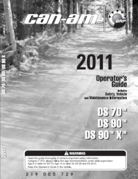
Сборник руководств на английском языке по эксплуатации и техническому обслуживанию квадроциклов Can-Am моделей DS 70/DS 90/DS 90X/DS 250/DS 650 2007-2011 годов выпуска.
- Издательство: BRP Inc.
- Год издания: 2006-2010
- Страниц: —
- Формат: PDF
- Размер: 31,7 Mb
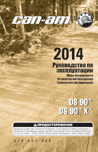
Сборник руководств на русском языке по эксплуатации и техническому обслуживанию квадроциклов Can-Am моделей DS 70/DS 90/DS 90X/DS 250/DS 450/DS 450X 2010-2014 годов выпуска.
- Издательство: BRP Inc.
- Год издания: 2009-2013
- Страниц: —
- Формат: PDF
- Размер: 47,1 Mb
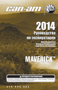
Сборник руководств на русском языке по эксплуатации и техническому обслуживанию квадроциклов Can-Am модели Maverick 2013-2014 годов выпуска.
- Издательство: BRP Inc.
- Год издания: 2012/2013
- Страниц: 158/138
- Формат: PDF
- Размер: 70,1 Mb
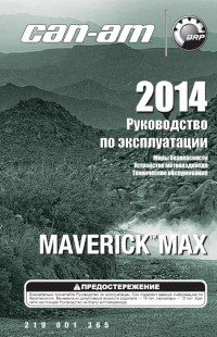
Руководство на русском языке по эксплуатации и техническому обслуживанию квадроциклов Can-Am модели Maverick Max 2014 года выпуска.
- Издательство: BRP Inc.
- Год издания: 2013
- Страниц: 142
- Формат: PDF
- Размер: 5,7 Mb
Руководство на английском языке по эксплуатации и техническому обслуживанию квадроциклов Can-Am модели Outlander 400 EFI 2009 года выпуска.
- Издательство: BRP Inc.
- Год издания: 2009
- Страниц: 148
- Формат: PDF
- Размер: 9,6 Mb

Сборник руководств на русском языке по эксплуатации и техническому обслуживанию квадроциклов Can-Am моделей Outlander/Outlander Max 400/500/650/800/1000 2006-2014 годов выпуска.
- Издательство: BRP Inc.
- Год издания: 2006-2013
- Страниц: —
- Формат: PDF
- Размер: 214,3 Mb

Руководство на английском языке по техническому обслуживанию и ремонту мотовездеходов Can-Am моделей Outlander 500/650/800 и Renegade 500/800 2007-2008 годов выпуска.
- Издательство: BRP Inc.
- Год издания: —
- Страниц: 504
- Формат: PDF
- Размер: 28,9 Mb
Сборник руководств на русском языке по эксплуатации и техническому обслуживанию квадроциклов Can-Am модели Renegade 500/800R/1000 2010-2014 годов выпуска.
- Издательство: BRP Inc.
- Год издания: 2009-2013
- Страниц: —
- Формат: PDF
- Размер: 61,1 Mb

Руководство на русском языке по эксплуатации и техническому обслуживанию трициклов Can-Am модели Spyder RS 2011 года выпуска.
- Издательство: BRP Inc.
- Год издания: 2010
- Страниц: 150
- Формат: PDF
- Размер: 18,8 Mb
Руководство на русском языке по эксплуатации и техническому обслуживанию трициклов Can-Am модели Spyder RT 2011 года выпуска.
- Издательство: BRP Inc.
- Год издания: 2010
- Страниц: 178
- Формат: PDF
- Размер: 12,3 Mb
Руководство на русском языке по техническому обслуживанию и ремонту трициклов Can-Am моделей Spyder GS и Spyder RS 2008-2011 годов выпуска.
- Издательство: BRP Inc.
- Год издания: 2011
- Страниц: 698
- Формат: PDF
- Размер: 91,1 Mb

Руководство на русском языке по техническому обслуживанию и ремонту трициклов Can-Am модели Spyder RT 2010-2011 годов выпуска.
- Издательство: BRP Inc.
- Год издания: 2011
- Страниц: 782
- Формат: PDF
- Размер: 85,1 Mb
Table of Contents
2
Safety Notice
9
General Information
10
Vehicle Information
11
Engine Emissions Information
11
Model Number
11
Vehicle Identification Number (VIN)
11
Self-Locking Fasteners Procedure
12
Loctite Application Procedure
12
Owner Responsibility
12
ERA Emission Regulations
12
Stud in Blind Holes
13
Preassembled Parts
13
Adjusting Screw
13
Stripped Thread Repair
14
Gasket Compound
14
Standard Thread Repair
14
Repair of Small Holes/Fine Threads
14
Tightening Torques
15
Mounting on Shaft
15
Case-In Components
15
Mounting with a Press
15
Fastener Grade/Torque
16
Maintenance Chart
20
Preseason Preparation
24
Storage Procedures
26
Fuel Stabilizer
26
Engine Lubrication
26
Rags Installation
26
Coolant Density
27
Drive and Driven Pulleys Protection
27
Vehicle Cleaning
27
Vehicle Protection
27
Special Procedures
28
Service Products
28
Turn over
28
ATV Immersion
28
Troubleshooting Chart
30
Starter Does Not Turn
30
Starter Turns, but Does Not Crank the Engine
31
Starter Motor Keeps Running
31
High Engine Operating Temperature
31
Battery Not Charging or Charging Voltage Inadequate
32
Low or no Oil Pressure/High Oil Consumption
33
Oil Contamination
33
Unusual Engine Noise And/Or Vibration
34
Oil Contamination on Cylinder And/Or Head
34
Unusual Engine Noise And/Or Vibrations
34
Unusual Gearbox Noise And/Or Vibrations
34
Gear Indication Fails
35
Gear(S) Is (Are) Hard to Shift
35
Wheel Drive Indication Fails
37
Wheel Drive Does Not Engage or Disengage
37
Unusual Acceleration Behavior
37
Engine Maximum RPM Is too High and Top Speed Is Not Reached
38
Drive Pulley Noise in Idle Speed
38
Drive Pulley Noise When Accelerating/Decelerating
38
Vibrations Originating from Drive Pulley
39
Vibrations Originating from Driven Pulley
39
Pulley’s Do Not Down/Up Shift Properly
39
Belt Glazed Excessively or Having Baked Appearance
39
Belt Worn Excessively in Top Width
40
Belt Disintegration
40
Cracks between Cogs
40
Engine Cranks but Fails to Start
40
Engine Does Not Start
41
Engine Hard to Start
41
Engine Suddenly Turns off
41
Engine Backfires
42
Engine Does Not Offer Maximum Power And/Or Does Not Reach Maximum Operating RPM
43
Engine Removal and Installation
45
Service Tools
45
Engine Removal
46
Vehicle and Engine Preparation
46
Engine Installation
52
Final Assembly Procedure
52
Engine Mount Replacement
53
Air Intake System
55
Air Filter Housing
56
Air Filter Removal
57
Air Filter Housing Removal
57
Air Filter Housing Installation
59
Restrictor Removal
59
Restrictor Installation
59
Exhaust System
61
Front Exhaust Pipe Inspection
62
Front Exhaust Pipe Removal
62
Front Exhaust Pipe Installation
62
Muffler Removal
63
Muffler Installation
63
«Y» Exhaust Pipe Removal
63
«Y» Exhaust Pipe Installation
63
Fuel Tank Protector Removal
64
Fuel Tank Protector Installation
64
Lubrication System
65
Lubrication System Components
66
Engine Oil
68
Recommended Oil
68
Engine Oil Viscosity
68
Engine Oil Level Verification
68
Engine Oil Pressure
69
Oil Filter Removal
69
Oil Pressure Switch (OPS)
70
Oil Filter Inspection
70
Oil Filter Installation
70
Oil Pressure Switch Activation
70
Engine Oil Pressure Regulator
71
Oil Pressure Switch Removal
71
Oil Pressure Switch Installation
71
Oil Pump Removal
72
Oil Pump Inspection
72
Oil Pump Installation
73
Engine Oil Strainer Removal
74
Engine Oil Strainer Cleaning and Inspection
74
Reed Valve Removal
74
Reed Valve Inspection
74
Cooling System Service Tools
75
Radiator
76
Water Pump
77
Cooling System Leak Test
78
Coolant Replacement
79
Recommended Coolant
79
Draining the System
79
Refilling the System
79
Thermostat Removal
80
Radiator Cap
81
Coolant Tank
81
Thermostat Installation
81
Radiator Installation
81
Coolant Temperature Sensor (CTS)
82
Radiator Fan Relay (R1)
82
Relay Installation
82
Relay Operation Test
82
Radiator Fan Operation
83
Radiator Fan Test
84
Water Pump Housing
85
Radiator Fan Removal
85
Water Pump Housing Removal
85
Radiator Fan Installation
85
Water Pump Impeller
86
Water Pump Shaft and Seals
86
Water Pump Housing Inspection
86
Water Pump Housing Installation
86
Shaft/Seal Installation
88
Magneto System
91
Magneto Cover Removal
93
Magneto Cover Inspection and Cleaning
93
Magneto Cover Installation
93
Stator Removal
94
Stator Inspection
94
Stator Installation
94
Rotor Removal
95
Rotor Inspection
95
Rotor Installation
95
Sprag Clutch Removal
96
Sprag Clutch Inspection
96
Sprag Clutch Installation
96
Sprag Clutch Gear Removal
97
Sprag Clutch Gear Inspection
97
Starter Drive Gears
97
Sprag Clutch Gear Installation
97
Gear Removal
98
Gear Inspection
98
Gear Installation
98
Intake Manifold, Cylinder Head and Cylinder
99
Intake Manifold
100
Cylinder Head No.1
101
Cylinder Head No.2
102
Cylinders and Pistons
103
Maintenance
104
Valve Adjustment
104
Valve Clearance
104
Leak Test Inspection
105
Intake Manifold Removal
107
Valve Cover Removal
108
Intake Manifold Inspection
108
Intake Manifold Installation
108
Timing Chain Tensioner Removal
109
Timing Chain Tensioner Inspection
109
Timing Chain Tensioner Installation
109
Camshaft Timing Gear Removal
110
Camshaft Timing Gear Inspection
110
Camshaft Timing Gear Installation
110
Rocker Arm Removal
112
Rocker Arm Inspection
112
Timing Chain
113
Rocker Arm Installation
113
Rocker Arm Shaft
113
Cylinder Head Removal
114
Cylinder Head Inspection
114
Camshaft
115
Cylinder Head Installation
115
Camshaft Timing
115
Camshaft Timing Cylinder 2
116
Camshaft Timing Cylinder 1
117
Camshaft Inspection
119
Valve Spring Removal
120
Camshaft Installation
120
Valve Spring Inspection
121
Valve Spring Installation
121
Valve Removal
122
Valve Inspection
122
Valve Stem Seal
122
Valve Stem Diameter
122
Valve Installation
123
Valve Face and Seat
123
Valve Seat Contact Width
123
Valve Guide Removal
124
Valve Guide Inspection
124
Valve Guide Installation
124
Cylinder Removal
125
Cylinder Inspection
125
Cylinder Taper in Diameter
125
Cylinder Installation
126
Cylinder out of Round
126
Piston Removal
126
Piston Inspection
127
Piston/Cylinder Clearance
127
Piston Pin Diameter
128
Connecting Rod/Piston Pin Clearance
128
Piston Installation
129
Connecting Rod Small End Diameter
129
Piston Rings
131
Ring Removal
131
Ring Inspection
131
Ring Installation
131
Bottom End
133
Engine Drive Shaft
134
Crankcase and PTO Cover
135
Crankshaft
136
Oil Seal Removal
137
Engine Drive Shaft Removal
137
Engine Drive Shaft Inspection
137
Engine Drive Shaft Installation
138
PTO Cover Oil Seal Removal
139
PTO Oil Seal Inspection
139
PTO Oil Seal Installation
139
PTO Cover Removal
139
PTO Cover Inspection
140
Plain Bearing Replacement Procedure
140
Plain Bearing Removal
140
PTO Cover Installation
141
Plain Bearing Installation
141
Drive Gears Removal
142
Drive Gears Inspection
142
Drive Gear Installation
142
Timing Chain Removal (Magneto Side)
143
Timing Chain Removal (PTO Side)
143
Timing Chain Inspection
143
Timing Chain Installation
143
Timing Chain Guide
144
Chain Guide Inspection
144
Chain Guide Installation
144
Crankcase Disassembly
144
Crankcase Cleaning
145
Crankcase Inspection
145
Oil Strainer
145
Plain Bearing Replacement
146
Crankcase Assembly
147
Crankshaft Locking Procedure
148
Crankshaft Inspection
150
Crankshaft Axial Play
150
Connecting Rod Big End Axial Play
150
Connecting Rod Big End Radial Play
150
Crankshaft Radial Play MAG/PTO Side
151
Crankshaft Assembly
152
Crankshaft Radial Play (PTO Side Support Bearing)
152
Crankshaft Installation
153
Outlander 500
153
Outlander 650 and 800
153
Gearbox and 4X4 Coupling Unit
155
Gearbox Components and 4X4 Coupling Mechanism
156
Gearbox Housing and 4X4 Actuator Unit
157
Gearbox Oil Change
158
Draining Procedure
158
Gearbox Position Indicator Switches Removal
159
Gearbox Position Indicator Switches Installation
159
4WD Indicator Switch Removal
160
4WD Indicator Switch Test
160
4WD Indicator Switch Installation
160
Oil Seals Removal
160
Countershaft Oil Seal
161
Shift Shaft Oil Seal
161
Output Shaft Oil Seal
161
Output Shaft and Countershaft Oil Seal
161
Actuator Test
162
Actuator Removal
162
Output Shaft and Coupling Mechanism
164
Output Shaft Backlash Procedure
164
Coupling Sleeve Groove Width
167
Coupling Fork Claw Thickness
167
Gearbox Removal
169
Gearbox Disassembly
169
Bevel Gear Axial Clearance
169
Bearing Removal in Housing
173
Gearbox Inspection
173
Shift Forks
174
Shift Drum
174
Levers
174
Gears
174
Width of Shift Fork Engagement Groove
175
Intermediate Gear Shaft
175
Bevel Gear Adjustment
176
Bevel Gear Backlash Procedure
177
Bevel Gear Axial Clearance Procedure
178
Bearing Installation in Housing
179
Other Gearbox Components
180
Shifter Service Products
187
Transmission Lever
188
Shifter Lever Removal
188
Link Rod Removal
189
Shifter Lever Inspection
189
Shifter Lever Installation
189
Shifting Plate
190
Link Rod Inspection
190
Link Rod Installation
190
Shifting Plate Removal
190
Shifting Plate Inspection
191
Shifting Plate Installation
191
Overview
193
Front
193
Engine Management System Overview
193
Operating Principle
194
Air Induction
194
Fuel System
194
Throttle Body
194
Fuel Rail
195
Fuel Pump Module
195
Fuel Pressure Regulator
195
Fuel Filter
195
Electrical System
196
Engine Control Module (ECM)
196
Power Distribution
196
Engine Management System
198
Electronic Fuel Injection
198
Ignition
198
ECM and VFB Interaction with the Electrical System
198
Engine Modes of Operation
199
Ignition Timing
199
Vehicle Speed Limiter
199
Limp Home Mode
199
Monitoring System
200
Diagnostic Mode
200
Battery Voltage Warning Device
200
Low Oil Pressure Warning Device
200
Engine Management System Flow Chart
201
EMS Diagnostic
203
On-Board Diagnostic
203
Fault Codes
204
TPS (Throttle Position Sensor) Faults
204
TPS «Out of Range» Fault
204
Fault Code P2119
204
Fault Code Table
205
Adjustment and Repair Procedures
213
Diagnostic Tools
215
Resistance Measurement
215
ECM Connectors
216
Engine Connector
216
Temperature Sensor Table
216
Basic Adjustments
217
Idle Speed
217
Throttle Cable
217
Closed Throttle and Idle Actuator Reset
218
Repair Procedures
219
Main Relay
219
D1 Diode (ECM)
219
Diode (D1) Installation
219
Diode (D1) Test
220
Quick Test to Validate ECM Operation
220
ECM Power Supply and Ground Pinout
220
ECM Power Supply Verification
220
If ECM Works When Bypassing Relay
222
ECM Replacement
222
Fuel Injector
223
Security Exchange
223
Leakage Test
223
Electrical Test
223
Fuel Injector Replacement
225
Fuel Injector Removal
225
Fuel Injector Installation
225
Fuel Rail Replacement
226
Fuel Rail Removal
226
Fuel Rail Installation
226
Mechanical Inspection
227
Electrical Inspection
227
Throttle Body Replacement
227
Throttle Position Sensor (TPS)
230
TPS Wear Test
230
TPS Resistance Test
231
TPS Input Voltage Test
231
TPS Replacement
231
Idle Bypass Valve (IBV)
232
IBV Information in B.U.D.S. Software
232
IBV Resistance Test
232
IBV Visual Inspection
233
Crankshaft Position Sensor (CPS)
234
CPS Resistance Test
234
CPS Replacement
234
Camshaft Position Sensor (CAPS)
235
CAPS Voltage Test
235
Manifold Air Pressure and Temperature Sensor (Mapts)
236
CAPS Replacement
236
Sensor Pressure Function
236
Voltage Test
236
Quick Test
237
Sensor Temperature Function
237
Resistance Test
237
MAPTS Replacement
237
CTS Resistance Test
238
CTS Replacement
238
Fuel Tank and Fuel Pump
239
Fuel Tank Leak Test Inspection
241
Check Valve and Pressure Relief Valve
242
Fuel Pressure Test
244
Fuel Hose and Oetiker Clamps
245
In-Line Fuel Filter
245
Fuel Hose Replacement
245
Oetiker Clamp Replacement
245
Fuel Tank Draining
246
Fuel Tank Removal
246
Fuel Tank Protector
247
Fuel Tank Inspection
247
Fuel Tank Installation
247
Fuel Pump Circuit Test
248
Fuel Pump Power Supply
248
Fuel Pump Ground Circuit
249
Fuel Pump Removal
249
Fuel Pump Installation
249
Fuel System Diagnostic Flow Chart
250
Communication Tools and B.U.D.S. Software
251
Multi-Purpose Interface (MPI)
251
MPI Supply
251
Connections with Vehicle
251
Multi-Purpose Interface-2 (MPI-2)
252
MPI-2 Supply
253
B.U.D.S. Software
253
Changes in ECM
254
Ignition System
255
Ignition Switch
255
Switch Resistance Test
255
Switch Wiring Test (Ignition Function)
256
Switch Wiring Test (DESS Function)
256
Engine Run/Stop Switch
257
Switch Resistance Test (Ignition Function)
257
Switch Resistance Test (DESS Function)
257
Ignition Coil Input Voltage
258
Ignition Coil Resistance Test
259
Spark Plug Removal
260
Troubleshooting Fouled Spark Plug
260
Spark Plug Analysis
260
Spark Plug Installation
260
Charging System
263
Magneto
263
Voltage Regulator/Rectifier
263
DC Current Test with an Inductive Ammeter
264
DC Current Test with a Multimeter
264
Stator
266
Static Test: Continuity
266
Static Test: Insulation
267
Dynamic Test: AC Voltage
267
Battery Information
268
Battery Troubleshooting
268
Discharged or Weak Battery
268
Battery Unloaded Test
268
Battery Removal
269
Battery Cleaning
269
Battery Inspection
270
Battery Storage
270
Main Ground
271
Starting System
273
Engine Cranking Conditions
273
Ignition Switch and Engine Run/Stop Switch
273
Electrical Cable and Connections
273
Fuses
274
D2 Diode (Starter Solenoid)
274
Start Button
275
Start Button Resistance Test
275
Start Button Wiring Test
275
Starting Solenoid
276
Solenoid Signal Test
277
Electric Starter
278
Starter Test
278
Digitally Encoded Security System (DESS)
281
DESS Key Programming
281
Lights, Gauge and Accessories
283
Diagnostic
283
Checking for Shorts between 2 Wires
283
Recommended Tools
283
Electrical Connectors
284
Fuses in Front Service Compartment
284
Fuse Located at the Rear
284
Accessory Relay (R3)
285
Multifunction Gauge
286
Unit Selection (MPH Vs Km/H)
286
Gauge Operation
286
Tachometer
289
Transmission Position Display
289
Fuel Level Display
289
Indicator Lamps
290
Multifunction Display (Normal Display Mode)
290
Multifunction Display (Temporary Display Mode)
291
Multifunction Display Codes/Messages
291
Function Display Problems
293
Fuel Level
293
2/4WD Pilot Lamp
293
HI Beam Pilot Lamp
293
Multifunction Gauge Pinout
294
Multifunction Gauge Removal
295
Multifunction Gauge Installation
295
New Multifunction Gauge Registration (Coding)
295
Country Selection
295
Vehicle Speed Sensor (VSS)
296
Fuel Level Sender
297
Multifunction Switch
297
Low/Hi Beam Switch
298
Override Switch
298
12-Volt Auxiliary Power Outlet
299
12-Volt Auxiliary Power Outlet Test
299
12-Volt Power Outlet Removal
299
12-Volt Power Outlet Installation
299
Headlamp Test
300
Headlamp Bulb Replacement
300
Headlamp Beam Aiming
302
Headlamp Adjustment
302
Taillight Bulb Replacement
303
Winch Test
303
Winch Motor
303
Voltage Supply to Switch
303
Winch Control Switch
304
Winch Relay
304
Winch Removal
305
Winch Installation
305
D5 and D6 Diodes (Winch Relay)
306
Winch Control Switch Removal
306
Winch Control Switch Installation
306
Continuously Variable Transmission (CVT)
309
Drive Belt Removal
311
Drive Pulley
312
Drive Belt Inspection
312
Drive Belt Installation
312
Drive Pulley Removal
313
Drive Pulley Disassembly
314
Sliding Sheave
315
Fixed Sheave
315
Drive Pulley Cleaning
315
Drive Pulley Inspection
316
Drive Pulley Governor Cup
316
Drive Pulley Roller and Slider Shoe
316
Centrifugal Lever Bore Diameter
317
Centrifugal Lever Pivot Bolt Bore Diameter
317
Sliding Sheave Large Bushing
317
Drive Pulley Assembly
318
Sliding Sheave Small Bushing
318
Spring Free Length
318
Spring Sleeve Length
318
Friction Washer
319
Driven Pulley Removal
320
Bushings Bore Diameter
322
Bushing Bore Diameter
322
Wear on Teeth both Sides
322
Width on Top Surface
323
Wear on Contact Surface
323
Clutch Spring Squareness
323
CVT Air Guide Removal
325
CVT Air Guide Inspection
325
CVT Air Guide Installation
325
Front Drive
327
Tires and Wheels
329
Wheel Hub Removal
329
Wheel Hub Inspection
330
Wheel Hub Installation
330
Front Drive Shaft Removal
330
Drive Shaft Inspection
331
Drive Shaft Installation
331
Drive Shaft Boot Inspection
332
Drive Shaft Boot Removal
332
Drive Shaft Boot Installation
332
Front Differential Oil Level
332
Front Differential Oil Change
333
Front Differential Removal
333
Front Differential Inspection
334
Front Differential Disassembly
334
Ring Gear Carrier/Ring Gear
334
Pinion Gear
334
Ring Gear Adjustment
335
Backlash
335
Front Propeller Shaft Removal
336
Front Propeller Shaft Inspection
337
Front Propeller Shaft Installation
337
Propeller Shaft U-Joint Removal
337
Propeller Shaft U-Joint Installation
337
Rear Drive
339
Differential Protector Removal
342
Differential Protector Installation
342
Drive Shaft Removal
342
Rear Propeller Shaft
343
Steering System
351
Handlebar Grip Removal
353
Handlebar Grip Installation
353
Handlebar Cover Removal
353
Handlebar Cover Installation
353
Handlebar Inspection
354
Handlebar Installation
354
Steering Column Removal
354
Steering Column Inspection
354
Steering Column Bearing Removal
355
Steering Column Installation
355
Tie-Rod
355
Tie-Rod Removal
356
Tie-Rod Installation
356
Knuckle Removal
356
Knuckle Inspection
358
Wheel Bearing Inspection
358
Wheel Bearing Removal
358
Wheel Bearing Installation
359
Multifunction Switch Removal
359
Throttle Handle Removal
359
Multifunction Switch Installation
360
Handle Brake Removal
360
Handle Brake Hose Removal
360
Steering Alignment
360
Front Suspension
363
Shock Absorber and Spring Removal
367
Shock Absorber and Spring Disassembly
368
Shock Absorber and Spring Inspection
368
Lower Suspension Arm Protector Removal
369
Lower Suspension Arm Protector Installation
369
Lower Suspension Arm Inspection
369
Lower Suspension Arm Removal
369
Lower Suspension Arm Installation
370
Lower Ball Joint Removal
371
Lower Ball Joint Installation
371
Upper Suspension Arm Lubrication
372
Upper Suspension Arm Inspection
372
Upper Suspension Arm Removal
372
Upper Suspension Arm Installation
373
Upper Suspension Arm Bracket Removal
373
Upper Suspension Arm Bracket Inspection
374
Upper Suspension Arm Bracket Installation
374
Upper Ball Joint Inspection
374
Upper Ball Joint Removal
374
Upper Ball Joint Installation
375
Rear Suspension
377
Rear Shock Removal
379
Rear Shock Disassembly
379
Rear Shock Inspection
380
Rear Shock Assembly and Installation
380
Torsion Bar Removal
380
Torsion Bar Inspection
381
Torsion Bar Installation
381
Trailing Arm Removal
381
Trailing Arm Inspection
382
Trailing Arm Installation
382
Trailing Arm Bearings Inspection
382
Trailing Arm Bearings Removal
382
Trailing Arm Bearings Installation
384
Front and Rear Brakes
385
Hydraulic Brakes System
389
Parking Brake
389
Brake Recommended Fluid
389
Brake Fluid Level
389
Brake Fluid Replacement
390
Brake Fluid Draining
390
Brake Fluid Filling and Bleeding
390
With a Vacuum Pump
390
Rear Brake Light Switch Inspection
391
Rear Brake Light Switch Test
391
Rear Brake Light Switch Removal
392
Rear Brake Light Switch Installation
392
Front Brake Light Switch Inspection
392
Parking Brake Mechanism Removal
392
Front Brake Light Switch Installation
393
Brake Lever Removal
393
Brake Lever Installation
393
Front Master Cylinder Removal
393
Front Master Cylinder Disassembly
394
Front Master Cylinder Assembly
394
Front Master Cylinder Installation
394
Rear Master Cylinder Removal
394
Rear Master Cylinder Disassembly
395
Rear Master Cylinder Inspection and Lubrication
395
Rear Master Cylinder Assembly
395
Rear Master Cylinder Installation
396
Caliper Removal
396
Caliper Disassembly
397
Caliper Inspection
397
Caliper Assembly
397
Brake Pads Removal
397
Brake Pads Installation
398
Brake Disc Inspection
399
Brake Disc Removal
399
Brake Disc Installation
400
Brake Pedal Removal
400
Brake Pedal Installation
400
Brake Hoses Inspection
400
Brake Hoses Removal
401
Brake Hoses Installation
401
Body
403
Outlander Series Body Parts (Front View)
404
Outlander Series Body Parts (Rear View)
405
Outlander Series Body Parts (Side View)
406
Outlander Series Seat
407
Outlander Series XT Package
408
Renegade Models Body Parts (Front View)
409
Renegade Models Body Parts (Rear View)
410
Renegade Models Body Parts (Side View)
411
Renegade Models Seat
412
Vehicle Care
413
Plastic Rivet
413
Decal Removal
413
Decal Installation
413
Seat Removal
414
Seat Installation
415
Seat Cover Replacement
415
Central Panel Removal
415
Central Panel Installation
416
Dash Board Removal
416
Side Panel Removal
416
Side Panel Installation
416
Footrest Removal
417
Inner Fender Removal
417
Inner Fender Installation
417
Bumper Removal
417
Bumper Installation
418
Front Bumper/Front Skid Plate/Front Fascia Removal
418
Luggage Rack Removal
419
Luggage Rack Installation
419
Fender Removal
419
Fender Installation
421
Fender Support Removal
422
Fender Support Installation
422
Frame
423
Footrest Support Removal
425
Footrest Support Inspection
425
Battery Support Removal
425
Battery Support Installation
426
Hitch Removal
426
Hitch Installation
426
Hook Removal
426
Hook Inspection
427
Hook Installation
427
Frame Cleaning
427
Frame Welding
427
Technical Specifications
429
Outlander Series
429
Renegade Models
439
Deutsch Connectors
449
Removal from Engine Connector Bracket
449
Connector Disassembly
449
Terminal Removal
451
Terminal Crimping (Kostal)
452
Multifunction Speedometer Connector
453
Battery and Starter Cable Terminals
454
Crimping
454
Wiring Diagrams
457
Wiring Connectors Coding
457
Wire Colors
457
Wire Gauge
457
Wire Location in Connector
458
Distribution System
459
Injection/Ignition System
461
Cooling System
463
- Скачать руководство по ремонту BRP Can-Am Outlander Series
Данный раздел посвящен редким книгам технического содержания на скачку
На этой странице вы можете бесплатно скачать руководство по ремонту квадроцикла BRP Can-Am Outlander Series /
МАХ Series. Благодаря подробным инструкциям книги ремонт указанной модели квадроциклов станет доступным не только профессиональным автотехникам, но и любителям этого вида спорта.
Руководство по ремонту квадроцикла BRP Can-Am Outlander Series / МАХ Series
Это пособие поможет владельцам и ремонтникам техники профессионально подойти к ремонту квадроцикла BRP Can-Am Outlander Series / МАХ Series. Книга в доступной, но точной форме отражает процесс исправления неисправностей данной техники.
скачать руководство бесплатно
Правила данной темы. Данная тема создана для технической литературы и документации по технике Can-am. Постепенно в нее буду скидывать все, что удалось найти, купить, выпросить, слямзить и т.д. У кого что есть, тоже просьба не стесняться, скидывайте описание и ссылку в личку, буду добавлять со ссылкой на автора в первый пост, чтобы полезное не утонуло в куче страниц. В самих постах ссылки размещать не надо. В постах можно писать запросы на поиск литературы, которые буду дублировать также в первом посте.
Сервисные каталоги Can-am в удобной програмной оболочке.
Полное описание возможностей программы и скриншоты здесь: http://www.ebay.co.uk/itm/ws/eBayISAPI.dll?ViewItem&item=170856984055&ssPageName=ADME:L:OU:GB:1123
Файлы для скачивания и краткое содержание:
1. для Win
На Гугл диске::https://drive.google.com/file/d/0B7lKlyMaWC7gTlNTcGpMV1RINnc/edit?usp=sharing
На Яндекс диске: https://yadi.sk/d/mRn43EzcjQ5TW
— (2007-2012) Outlander 400 650
— (2007-2012) Outlander Renegade 500
— (2007-2012) Outlander Renegade 800
2. для Win
На Гугл диске: https://drive.google.com/file/d/0B7lKlyMaWC7gQllzekNfR3lCdG8/edit?usp=sharing
На Яндекс диске: https://yadi.sk/d/KhiWkzWojQ5ZN
— (2006-2012) Outlander 400
— Outlander 800
3. для Mac
На Гугл диске: https://drive.google.com/file/d/0B7lKlyMaWC7gLUhWOFpUNnpkZjg/edit?usp=sharing
На Яндекс диске: https://yadi.sk/d/fVJk2gAWjQ5eb
— (2007-2012) Outlander 400 650
— (2007-2012) Outlander Renegade 500
— (2007-2012) Outlander Renegade 800
4. Сервис-мануал на коммандер 2012
На Гугл диске: https://drive.google.com/file/d/0B7lKlyMaWC7gbVJtc250UmFWbVE/edit?usp=sharing
На Яндекс диске: https://yadi.sk/d/HaVpkx_ujQ5ky
Файл PDF. Для его просмотра нужна последняя версия adobe acrobat reader. Предоставлен комрадом _dh_, за что ему братское спасибо!
5. Сервис-мануал BRP 2005 года (Rally 200, Sarasota 1000, Traxter Stries) Файл PDF
На Яндекс диске: https://yadi.sk/d/YemPHE1mjQ6k6
6. Сервис мануал на ауты 2014 года (близки и к 2013) (Includes all DPS (power steering), XT, ARS (air ride suspension) & Max (2-Seater) versions of the models listed below):
2014 Can-Am Outlander 500
2014 Can-Am Outlander 500 Max
2014 Can-Am Outlander 650
2014 Can-Am Outlander 650 Max
2014 Can-Am Outlander 800R
2014 Can-Am Outlander 800R Max
2014 Can-Am Outlander 1000
2014 Can-Am Outlander 1000 Max
2014 Can-Am Outlander 650 XMR (includes Supplement)
2014 Can-Am Outlander 1000 XMR (includes Supplement)
2014 Can-Am Renegade 500
2014 Can-Am Renegade 800R
2014 Can-Am Renegade 1000
Файл PDF. Для его просмотра нужна последняя версия adobe acrobat reader. Предоставлен комрадом aster, за что ему братское спасибо!
На Яндекс диске: https://yadi.sk/d/7FPWKZkMn25ng
————————————————————————————————————————————-
Примечание!!! ОЧЕНЬ ВАЖНОЕ!!!
— Кнопка «спасибо» в правом нижнем углу
— Пользуйтесь на здоровье!!! 
P.S. Файлы перезалиты на мой Гугл и Яндекс диск. В случае отсутствия файлов для скачивания по указанным ссылкам — пишите в личку — перезалью.


