- Manuals
- Brands
- Alpha Manuals
- Inverter
- 6000
- User manual
-
Contents
-
Table of Contents
-
Troubleshooting
-
Bookmarks
Quick Links
Related Manuals for Alpha 6000
Summary of Contents for Alpha 6000
-
Page 2: Preface
Preface Preface Thank you for buying ALPHA6000/6100 series inverter made by Shenzhen ALPHA Inverter Co., Ltd. To satisfy the high performance needs, ALPHA6000/6100 series inverters use magnetic flux vector control method to achieve high torque at low speed and low-noise at steady running.
-
Page 3
Preface Danger! This system contains voltages that may be as high as 400 volts! Electric shock can cause serious or fatal injury. Only qualified personnel shall wire the drive. Please cut off the power before wiring and inspecting. It is not permissible to touch PCB or interior components before battery control lamp goes off or until 5 minutes after the power has been removed. -
Page 4: Table Of Contents
Contents Contents Preface ……………………..1 Contents …………………….. 3 Chapter 1 Purchase Inspection ………………6 1.1 Unpacking Inspection ………………6 1.2 Naming Rule ………………… 6 1.3 Nameplate of Inverter ………………7 Chapter 2 Installation and Wiring ………………. 8 2.1 Exterior Size and Mounting Size (See Appendix 1) ……… 8 2.2 Mounting Place Requirement and Management ……….
-
Page 5: Table Of Contents
Contents 3.3.1 Operation Mode of Inverter …………..48 3.3.2 Checkpoints Before Operation …………..49 3.3.3 Operation Checkpoints …………….49 3.3.4 A Trial Run ………………..50 3.4 Commissioning of Keyboard …………….51 3.5 Operation of Control Circuit Terminal …………52 Chapter 4 Parameter Index ………………. 54 Chapter 5 Parameter Introductions …………….
-
Page 6: Table Of Contents
Contents 7.2.4 Leakage Current Protector …………..177 7.2.5 Capacitor Box ………………177 Chapter 8 Maintenance ………………..178 8.1 Inspection and Maintenance …………….. 178 8.1.1 Daily Inspection ………………178 8.1.2 Regular Maintenance …………….179 8.1.3 Replace Device at Regular Intervals …………182 8.2 Storage and Keeping ………………
-
Page 7: Chapter 1 Purchase Inspection
Chapter 1 Purchase Inspection Chapter 1 Purchase Inspection 1.1 Unpacking Inspection All inverters have passed the strict test before delivery. After unpacking, please check if the product was damaged by careless transport, the product specification, model is complied with the order, and if it has a quality check passed mark. If there is any problem, please contact the supplier.
-
Page 8: Nameplate Of Inverter
Chapter 1 Purchase Inspection 1.3 Nameplate of Inverter On the right side of the bottom plate of inverter, there is a nameplate, which marks the model and rated values of inverter. See the following figure: Inverter types Rated input voltage,current and frequency Motor output power,rated current and frequency Barcode information Nameplate of Inverter…
-
Page 9: Chapter 2 Installation And Wiring
Chapter 2 Installation and Wiring Chapter 2 Installation and Wiring 2.1 Exterior Size and Mounting Size (See Appendix 1) 2.2 Mounting Place Requirement and Management Attention · Don’t carry the inverter by its cover. The cover cannot support the weight of the inverter and may drop.
-
Page 10: The Ambient Temperature
Chapter 2 Installation and Wiring 2.2.2 The Ambient Temperature In order to enhance operating reliability of the inverter, be sure where the inverter mounted has a good ventilation; when the inverter is used in a closed case, cooling fans or an air-conditioning must be installed to keep the ambient temperature below 40℃. 2.2.3 Preventive Measures Installing the inverter, please set a shield to prevent metal debris falling into it, and remove the shield after installing.
-
Page 11
Chapter 2 Installation and Wiring Fig 2-2 S2R4GB~S2R75GB Main Circuit Wiring Table2-1 S2R4GB~S2R75GB main circuit terminals function Terminal Symbol Terminal name and function L, N Single-phase 220V AC supply input terminals +, PB Reserved terminals for braking resistor U, V, W Three-phase AC output terminals Earth terminal Fig 2-3 S21R5GB~S22R2GB Main Circuit Wiring… -
Page 12
Chapter 2 Installation and Wiring Fig. 2-4 3R75GB/31R5PB~3004GB/35R5PB Main Circuit Wiring Table2-2 3R75GB/31R5PB~3004GB/35R5PB main circuit terminals function Terminal Symbol Terminal name and function L, N Three-phase 220V AC supply input terminals +, PB Reserved terminals for braking resistor DC negative bus output terminal U, V, W Three-phase AC output terminals Earth terminal… -
Page 13
Chapter 2 Installation and Wiring Table 2-4 35R5GB/37R5PB~3015GB/3018PB main circuit terminals function Terminal Symbol Terminal name and function R, S ,T Three-phase 380V AC supply input terminals P1,+/B1 Terminals for an external DC reactor +/B1, B2 Terminals for an external braking resistor DC negative bus output terminals U,V,W Three-phase AC output terminals… -
Page 14
Chapter 2 Installation and Wiring Table 2-5 3018G/3022P~3055G/3075P main circuit terminals function Terminal Function R, S, T Three-phase 380V AC supply input terminals P1,+ Terminals for an external DC reactor Terminal for an external DC negative bus U, V, W Three-phase AC output terminals Earth terminal Attention: When DC reactor is not connected, please short “P1”… -
Page 15
Chapter 2 Installation and Wiring Fig. 2-8 3400G~3500G Main Circuit Wiring Table 2-6 3160G/3185P~3500G main circuit terminals function Terminal Function R, S, T Three-phase 380V AC supply input terminals P1,+ Terminals for an external DC reactor DC negative bus output terminals U, V ,W Three-phase AC output terminals Earth terminal… -
Page 16
Chapter 2 Installation and Wiring Operation 2.4.2 Main Circuit Wiring When the motor is running, please make sure if it is in positive rotation while the motor receives positive rotation command. If the motor is in reverse rotation, the rotation direction of the motor can be changed by exchanging any two wires of output terminals (U, V, and W) of the inverter. -
Page 17
Chapter 2 Installation and Wiring output cables and the control signal cables greater than 30 cm, the effect of conduction interference will obviously decrease too. Countermeasures to RFI: The input cables, output cables and the inverter itself would produce RFI. Placing noise filters both at input and output sides, and shielded with metal shell would reduce RFI.. -
Page 18: Control Circuit Connection
Chapter 2 Installation and Wiring 2.5 Control Circuit Connection 2.5.1 Function of Control Circuit Terminals Fig. 2-11 S2R4GB~S2R75GB Arrangement of Control Circuit Terminals Fig. 2-12 S21R5GB~3004GB/35R5PB Arrangement of Control Circuit Terminals Fig. 2-13 35R5GB/37R5PB~3500GB Arrangement of Control Circuit Terminals In order to reduce interference and attenuation of control signal, the length of control cables should be limited in 50m and away from power cables for more than 30cm.
-
Page 19
Chapter 2 Installation and Wiring Function of Control Circuit Terminals Table 2-8 Function of control circuit terminals Category Terminal Name Functions Specification Receive voltage/current input. Voltage or current Input voltage range: input mode are Analog input1 0~10 V selectable by (Input resistance: data-chosen-switch 100 kΩ) -
Page 20
Chapter 2 Installation and Wiring Category Terminal Name Functions Specification Standard RS-485 communication 485+ RS485+ interface RS485 Not isolated with communicatio n interface Please use 485- RS485- twisted-pair or shielded cable Optical-isolator input Multi- Input resistance: function input It can be defined as R=3.9 kΩ… -
Page 21
Chapter 2 Installation and Wiring Category Terminal Name Functions Specification It can be defined as Optical-isolator input Multi- multi-function on- off Input resistance: function input input terminal. See R=3.9 kΩ terminal 6 section 5.4, Chapter 5 for Maximum input (only details. -
Page 22
Chapter 2 Installation and Wiring Category Terminal Name Functions Specification TA-TB: Normally close; TA-TC: Normally It can be defined as open. multi-function output Programmable Capacity of contacts: terminal of relay. See relay output 250 VAC/2 A section 5.4, Chapter 5 for (COSΦ=1) details. -
Page 23
Chapter 2 Installation and Wiring Category Terminal Name Functions Specification Be shorted to 24V before delivery PLC is internal isolated with 24V. Notes: S2R4GB, S2R75GB model don’t have this Common function terminal of To use PLC for Common terminal of multi- following models, JP1 multi-function input… -
Page 24: Control Circuit Wiring
Chapter 2 Installation and Wiring 2.5.2 Control Circuit Wiring ●Wiring Analog Input Terminal AI1/AI2 terminals can accept analog signal input, operate Data-chosen-switch SW1 to select input voltage (0~10V) or input current (0~20mA). The wiring is shown as Figure 2-14: AI1/AI2 0~…
-
Page 25
Chapter 2 Installation and Wiring Inverter Shielded wire rear Grounding Fig 2-16 35R5GB/37R5PB~3500G Analog output terminal wiring diagram Notes: 1) Dialing SW1, SW2, SW3 to “I” represents current, dialing to “V” represents voltage. 2)Analog input and output signals are easily disturbed by exterior environment, so shielded cables must be used for wiring and the length of the cables should be as short as possible. -
Page 26
Chapter 2 Installation and Wiring If several inverters (Max 31) are connected in the network by RS485, wiring is especially important because the disturbance to the communication system increases, STP (Shielded Twisted Pair) must be used for communication BUS, you can connect the cables as follows: Fig. -
Page 27
Chapter 2 Installation and Wiring 3)Mount a toroid to the communication cable, or reduce the carrier frequency if the local conditions permit . Wire Multi-Function Input Terminals Multi-function input terminals of the inverter use a full-bridge rectifying circuit. PLC is the common terminal of terminals X1~X8(in 3R75GB/31R5PB~3004GB/35R5PB only X1~X5). -
Page 28
Chapter 2 Installation and Wiring +24V X1~X8 Fig. 2-21 Use an external supply(in 3R75GB/31R5PB~3004GB/35R5PB only X1~X5) Method 2 of Connections 1)Inverter’s internal +24V power supply is used and the external controller uses NPN transistors whose common emitters are connected, as shown in Figure 2-22. External t ll 24V DC… -
Page 29
Chapter 2 Installation and Wiring External 24V DC Shield wire near grounding Fig. 2-23 Drain connection method by using inverter’s internal +24 V power supply (in 3R75GB/31R5PB~3004GB/35R5PB only X1~X5) 3)Use external power supply by source connection method (Attention: be sure to disconnect the cable JP1 between PLC and 24V for models of 3R75GB~3004GB;… -
Page 30
Chapter 2 Installation and Wiring 4)Use external power supply by drain connection method (Attention: be sure to disconnect the cable JP1 between PLC and 24V for models of 3R75GB~3004GB; and disconnect wiring cable between models 35R5GB/37R5PB~3500G). External controller 20~30V 24V DC —… -
Page 31
Chapter 2 Installation and Wiring 2)Multi-function output terminals D0 as switching output can also use the external 9~30V power supply and the wiring method is shown in Figure 2-27. DC9~30V relay Fig. 2-27 Wiring method 2 of DO as switching output 3)Multi-function output terminals / Pulse output terminal DO as pulse output can use the internal 24V power supply and the wiring is shown in Figure 2-28. -
Page 32
Chapter 2 Installation and Wiring 4)Multi-function output terminals / Pulse output terminal DO as Pulse output can also use the external 9~30V power supply and the wiring is shown in Figure 2-29. +24V +24V 4.7K 20~30V Digital frequency meter Fig. 2-29 Wiring method 2 of DO as pulse output 5)Multi-function output terminals Y1 and Y2 can use the internal 24V power supply of inverter and the wiring method is shown in Figure 2-30. -
Page 33
Chapter 2 Installation and Wiring 6)Multi-function output terminals Y1 and Y2 can also use the external 9~30V power supply and the wiring method is shown in Figure 2-31. Fig. 2-31 Wiring method 2 of multi-function output terminal (only 35R5GB/37R5PB~3500G) Wiring of Relay Output Terminals TA, TB, TC and BRA, BRB, BRC (BRA, BRB, BRC is provided only in 35R5GB/37R5PB~3500G) If the inverter drives an inductive load (such as relay or contactor), then a surge… -
Page 34
Chapter 2 Installation and Wiring no longer than 15 meters, otherwise it wouldn’t work properly. (Remove the original keyboard of models of S2R4GB~3004GB/35R5PB, or the exterior can not work properly) Table 2-9 T568B standard connection Corresponding Number Color White/Orange Orange White/Green Blue White/Blue… -
Page 35: Wiring Of Inverter For Basic Operation
Chapter 2 Installation and Wiring 2.6 Wiring of Inverter for Basic Operation Braking Resistor (external optional) Circuit breake Motor Single phase 220V 50/60HZ Analog output 0/4 ~ 20mA 0/4 ~ 20mA current Multi-function input 1 0/2 ~ 10V 0/2 ~ 10V voltage Multi-function input 2 Multi-function input 3 Multi-function input 4…
-
Page 36
Chapter 2 Installation and Wiring Braking Resistor (connect optional parts externally) MCCB Motor Power Supply 3-phase 380V 50/60HZ Ground Analog output 0/4 ~ 20mA 0/4 ~ 20mA current Multi-function input 1 0/2 ~ 10V 0/2 ~ 0V voltage Multi-function input 2 Multi-function input 3 Multi-function input 4 Multi-function input 5… -
Page 37
Chapter 2 Installation and Wiring B r a k i n g R e s i s t o r DC reactor (connect optional (connect optional parts externally) parts externally) P1 +/B1 Motor Power Supply 3-phase 380V 50/60HZ Ground Analog output Multi-function input1 0/4 ~ 20mA 0/4 ~ 20mA current… -
Page 38
Chapter 2 Installation and Wiring DCL DC reactor Braking resistor (connect externally,optional or braking unit parts for 3132G/3160P or below) Motor Power Supply 3-phase 380V 50/60HZ Ground Analog output Multi-function input1 0/4 ~ 20mA 0/4 ~ 20mA current Multi-function input2 0/2 ~ 10V 0/2 ~ 0V voltage Multi-function input3… -
Page 39: Wiring Attention
Chapter 2 Installation and Wiring 2.7 Wiring Attention Be sure the input power supply of the inverter is cut off then you can remove or replace the motor. Be sure the inverter has stopped output then you can switch the motor or the power supply.
-
Page 40: Chapter 3 Operation
Chapter 3 Operation Chapter 3 Operation 1. Only turn on the input power supply after replacing the front DANGER cover. Do not remove the cover while the inverter is powered up. 2. When the retry function is selected, do not approach the inverter or the load, since it may restart suddenly after being stopped.
-
Page 41: Overview Of Keyboard
Chapter 3 Operation 3.1.1 Overview of Keyboard REMOTE TRIP Status indicator Frequency:Hz Roate speed:r/min r/min LED Display Current:A Percent% linear speed:m/s Displays set values of each function or monitoring values such as output Voltage:V frequency and current (4 digits). Increment key Programming key Decrement key >…
-
Page 42: Description Of Keystroke Function
Chapter 3 Operation Table 3-1 The LED monitoring objects Permission of Modify Monitoring object(Unit) value in running state PC.01=1 Output frequency before compensation (Hz) PC.02=1 Actual output frequency (Hz) PC.03=1 Output current (A) PC.04=1 Setting frequency (Hz blink) permission PC.05=1 Motor rotate speed (r/min) PC.06=1 Setting speed (r/min blink)
-
Page 43
Chapter 3 Operation Table 3-2 Description of keystroke function Name of key Key functions Enter or exit programming state. In monitoring state, press the PRG/ESC key to programming state. The first, enter function group menu, and press the “ENTER” key to enter function code and function parameter progressively;… -
Page 44: Description Of Led Digitals And Indicators
Chapter 3 Operation Name of key Key functions Press this button to change the direction of Direction switch rotation. See P0.05 function description for details. In keypad control mode, this key is used to stop STOP Stop/Reset key the inverter. Clear the failure and return to RESET normal state when there is a failure.
-
Page 45: Display State Of Keyboard
Chapter 3 Operation Indicator Display state Mean: Indicator the state of inverter Normal TRIP failure indicator Slow flicker Failure Keypad control state REMOTE command mode Terminal control state indicator Slow flicker Serial communication state 3.1.4 Display State of Keyboard The working state of this series inverter includes two states: stop state and running state. Stop State: If there is no running command input after the inverter is power on and initialized, or the inverter has received a stop command input, the inverter will come into stop state.
-
Page 46
Chapter 3 Operation >> By pressing the key, user can view the parameters value of stop state. If you want to see the details of fault information, press the key, the keyboard will go to programming state, to see the details, please see the parameter values of group PE. STOP RESET To reset the inverter, press the… -
Page 47: Operation Method Of Keyboard
Chapter 3 Operation In stop, running fault or warning state, press the PRG/ESC key , the inverter will come into programming state.(If the user has set the user password, please see chapter 5.16, description of PF.00). In programming state, there are three display menus, see figure 3-4.
-
Page 48
Chapter 3 Operation Display 0.00 50.00 49.99 49.50 40.00 0.00 of LED Operation of key The maximal Stop Keep on output turn left 1 3 seconds Turn left the step length trunning turnning, later,the time,seting frequency digital can reach the decrease keyboard will frequency encoder,the… -
Page 49: Run Command Mode Select
Chapter 3 Operation parameter value. The inverter parameters are protected. If function parameter value PF.01=1 or 2, the parameters are forbidden to be changed. This parameter protection function is to avoid operation mistake. To change the protection parameters, change value of function code PF.01 to zero, then all the parameters can be changed.
-
Page 50: Checkpoints Before Operation
Chapter 3 Operation PID closed loop operation: If PID close loop operation is selected by P0.01 (set the value to 9), the inverter will choose PID closed loop operation mode. In other word, it will come into PID adjustment as the PID feed and PID feedback. (see parameter group P7).
-
Page 51: A Trial Run
Chapter 3 Operation Switch of operation modes of this series inverter are as figure 3-8 description: Operation mode of inverter JOG active JOG running PID termianl PID running active Wobble frequency Wobble frequency running terminal running active PLC termianl PLC running active Termianl function: Common running…
-
Page 52: Commissioning Of Keyboard
Chapter 3 Operation Operation process of power up the inverter is as the following: Start wiring as the requirement stated in this manual wiring is right. the input voltate is right Power ON see output frequency monitor: 0.00Hz heard the sound of contactor indraft? Display fault code»CCF2″or no…
-
Page 53: Operation Of Control Circuit Terminal
Chapter 3 Operation Using the keyboard can take the following steps to realize the task: A typical operation pattern using the keyboard: Forward 30.00Hz Reverse P ower Frequency Forward Run Reverse Run S t op Set t ing 30.00Hz Figure 3-10 Operation sequence by keyboard Running and stop operation: Display -P0-…
-
Page 54
Chapter 3 Operation Forward 30.00Hz Power Frequency Running Stop setting Figure 3-13 Sequence of terminal operation Operation steps: Display -P0- P0.00 0.00 50.00 P0.01 -P0- 30.00 0.00 30.00 of LED Operation Open Close ENTER ENTER ENTER of key X1-COM X1-COM go to monitoring go from… -
Page 55: Chapter 4 Parameter Index
Chapter 4 Parameter Index Chapter 4 Parameter Index Attention: “○”means that the parameters can be changed during inverter running and stop state; “×”means that the parameters cannot be changed during running; “*” means that the actually measured value or fixed parameters cannot be changed; “-”…
-
Page 56
Chapter 4 Parameter Index Function MODBUS Function Name Range of settings Default Change code Address Keyboard 0: Forward P0.05 ○ 0105 direction setting 1: Reverse S2R4GB~3004GB/35R5PB : 0.10~650.0Hz P0.06 Basic Frequency 50.00Hz × 0106 35R5GB/37R5PB or above: 0.10~400.0Hz S2R4GB~3004GB/35R5PB : MAX [50.00Hz, Upper limit frequency, Reference frequency] Maximum… -
Page 57
Chapter 4 Parameter Index Function MODBUS Function Name Range of settings Default Change code Address 3004GB/35 R5PB or below: 0.0: Magnetic flux vector control 4.0% P0.19 Control mode ○ 0113 0.1~30.0%: Manual torque boost 35R5GB/37 R5PB or above: 0.0% Cut-off point P0.20 used for manual 0.00~50.00Hz… -
Page 58
Chapter 4 Parameter Index Function MODBUS Function Name Range of settings Default Change code Address Time of S-curve 10.0~80.0% (Acc/Dec Time) P1.07 60.0% ○ 0207 rising P1.06+P1.07≤90% 0: Deceleration to stop P1.08 Stop mode 1: Coast to stop × 0208 2: Dec +DC braking DC injection 0.00~MIN(50.00Hz, Frequency upper… -
Page 59
Chapter 4 Parameter Index P2: Auxiliary Operation Function MODBUS Function Name Range of settings Default Change code Address P2.00 Jog frequency 0.10~Upper limit frequency 5.00Hz ○ 0300 3132G/3160P or below: 0.1~3600s 3022G/3030P P2.01 Acc time of Jog ○ 0301 3160G/3185P or above: or below: 1.0~3600s 6.0s… -
Page 60
Chapter 4 Parameter Index Function MODBUS Function Name Range of settings Default Change code Address Multi-step P2.20 0314 frequency 10 Multi-step P2.21 0315 frequency 11 Multi-step P2.22 0316 frequency 12 0.00~Maximum frequency 0.00Hz ○ Multi-step P2.23 0317 frequency 13 Multi-step P2.24 0318 frequency 14… -
Page 61
Chapter 4 Parameter Index P3: I/O Terminal control This page only for 3004GB/35R5PB and below Function MODBUS Function Name Range of settings Default Change code Address 0: Close valid Terminal P3.00 1: Open valid (Normally open /close is × 0400 function mode not limited.) 0: NULL, No defined… -
Page 62
Chapter 4 Parameter Index This page only for 3004GB/35R5PB and below Function MODBUS Function Name Range of settings Default Change code Address 0~40: Ibid 41: Command channel switch to Keyboard control 42: Start PLC operation 43: Pause the PLC operating 44: Reset PLC stop status 45: Start Wobble frequency operating 46: Reset the Wobble frequency operating… -
Page 63
Chapter 4 Parameter Index This page only for 35R5GB/37R5PB and above Function MODBUS Function Name Range of settings Default Change code Address 0: Close valid Terminal P3.00 1: Open valid (Normally open /close is × 0400 function mode not limited.) 0:NULL, No defined 1: FWD: Running Forward 2: REV: Running Reverse… -
Page 64
Chapter 4 Parameter Index This page only for 35R5GB/37R5PB and above Function MODBUS Function Name Range of settings Default Change code Address 0~40: Ibid 41: Command channel switch to Multi-function Keyboard control P3.04 input selection × 0404 42: Start PLC operation Terminal X4 43: Pause the PLC operating 44: Reset PLC stop status… -
Page 65
Chapter 4 Parameter Index Function MODBUS Function Name Range of settings Default Change code Address Terminal UP/DN 1.00Hz P3.10 0.01~99.99Hz/s ○ 040A rate UP/DN reference P3.11 0.00~Frequency upper limit 10.00Hz × 040B amplitude 0: Receive STOP, UP/DN reference reset to zero 1: Receive STOP, UP/DN reference not Digital frequency reset to zero, and not save when… -
Page 66
Chapter 4 Parameter Index Function MODBUS Function Name Range of settings Default Change code Address Reserved 0~27: Ibid (3004GB/35R5PB 28: Fixed-length arrived, output a high or below) level signals P3.15 040F Terminal Y2 29: Standby function definition × 30: Zero-speed running (35R5GB/37R5PB Note: Function code or above) -
Page 67
Chapter 4 Parameter Index P4: Analog and Pulse Function Function MODBUS Function Name Range of settings Default Change code Address Analog Nonlinear 0:None 1:AI1 P4.00 × 0500 Selection 2:AI2 3: Pulse Min analog value P4.01 Input 1 (AI1 0.00~P4.03 0.10V ○… -
Page 68
Chapter 4 Parameter Index Function MODBUS Function Name Range of settings Default Change code Address Physical value 3 corresponding to P4.14 0.0~100.0% 100.0% ○ 050E Max pulse value Input Pulse input filter time constant 3 P4.15 0.01~50.00s 0.05s ○ 050F (pulse Input Terminal) P4.16… -
Page 69
Chapter 4 Parameter Index Function MODBUS Function Name Range of settings Default Change code Address Min output 0.00~ Max Pulse frequency output of P4.25 impulse frequency 0.00kHz ○ 0519 of DO P5: PLC Operating Function MODBUS Function Name Range of settings Default Change code… -
Page 70
Chapter 4 Parameter Index Function MODBUS Function Name Range of settings Default Change code Address Program Operating P5.16 10.0 ○ 0610 Timing T13 Program Operating P5.17 0.0~3600 10.0 ○ 0611 Timing T14 Program Operating P5.18 10.0 ○ 0612 Timing T15 Step T1 Program P5.19 ○… -
Page 71
Chapter 4 Parameter Index Function MODBUS Function Name Range of settings Default Change code Address Record of Program P5.35 0~15 0623 steps Program operating P5.36 0.0~3600 0624 Time P6: Wobble Frequency Operating Function MODBUS Function Name Range of settings Default Change code Address… -
Page 72
Chapter 4 Parameter Index Function MODBUS Function Name Range of settings Default Change code Address 0: AI1 terminal 1: AI2 terminal 2: Serial communication 3: Pulse feedback 4: |AI1-AI2| PID feedback P7.01 5: Reserved × 0801 selection 6: AI1+AI2 7: MIN (AI1, AI2) 8: MAX (AI1, AI2) 9: PG or single-phase speed measuring input… -
Page 73
Chapter 4 Parameter Index P8: Fixed-length Function Function MODBUS Function Name Range of settings Default Change code Address P8.00 Preset length Max[0.000,P8.06]~65.53 m 0.000m ○ 0900 0.000~65.53m (Save when power P8.01 Actual length 0.000m 0901 loss) P8.02 Rate of length 0.001~30.00 1.000 ○… -
Page 74
Chapter 4 Parameter Index Function MODBUS Function Name Range of settings Default Change code Address This value depends on PA.03 No-load current I0 0.1~999.9A × 0B03 the inverter model. This value depends on PA.04 Resistance of stator %R1 0.00%~50.00% ○ 0B04 the inverter model. -
Page 75
Chapter 4 Parameter Index Function MODBUS Function Name Range of settings Default Change code Address Output frequency (Hz) PC.01 0: No display 1: Display ○ 0D01 (before compensation) Output frequency (Hz) PC.02 0: No display 1: Display ○ 0D02 (Actual) PC.03 Output current(A) 0:No display;… -
Page 76
Chapter 4 Parameter Index Function MODBUS Function Name Range of settings Default Change code Address 0.1~999.9% Linear speed = Running frequency *PC.22 (no PG)) Linear speed = Rotate speed*PC.22 (PG) Linear speed display PC.22 Reference linear speed = reference 100.0% ○… -
Page 77
Chapter 4 Parameter Index Function MODBUS Function Name Range of settings Default Change code Address Input phase loss Pd.09 detection delay 2~255s × 0E09 time Output phase loss detection level (SP0) (Motor rated current Pd.10 0~100% × 0E0A corresponds to 100%) Reserved (S2R4GB,… -
Page 78
Chapter 4 Parameter Index PE: Running History Record Function MODBUS Function Name Range of settings Default Change code Address 0: NULL 1: Uu1: Bus under-voltage during running. 2: Uu2: Control circuit Under voltage 3: Uu3: Charging circuit in poor condition 4: OC1: Over-current in Acc process 5: OC2: Over-current in Dec process 6: OC3: Over-current in… -
Page 79
Chapter 4 Parameter Index Function MODBUS Function Name Range of settings Default Change code Address DC bus voltage at PE.04 0~1000V 0F04 last fault 0: StP : Stop Running status at 1: Acc: Acceleration PE.05 0F05 last fault 2: Dec: Deceleration 3: con: constant Fault history 1 PE.06… -
Page 80: Chapter 5 Parameter Introductions
Chapter 5 Parameter Introductions Chapter 5 Parameter Introductions 5.1 Basic Function (Group P0) P0.00 Reference frequency Range: 0~Maximum frequency【0.00Hz】 Note: P0.00 is active when P0.01 or P0.02 is 1, that is, the value can only be adjusted by keyboard digital encoder. P0.00 defines inverter’s frequency setting value. …
-
Page 81
Chapter 5 Parameter Introductions details. P0.03 Frequency setting selection Range: 0~5【0】 0: Frequency setting 1 1: Terminal Selection 2: Frequency setting 1+ Frequency setting 2 3: | Frequency setting 1- Frequency setting 2 | 4: Min(Frequency setting 1, Frequency setting 2) 5: Max(Frequency setting 1, Frequency setting 2) Note: … -
Page 82
Chapter 5 Parameter Introductions Terminal control: The user should define X1~X8 terminal to achieve RUN, F/R, FWD, REV, HLD and other running functions (see P3.01~P3.08) first, and then used the terminals to control the inverter Start, Stop. etc. Serial communication: Users connected the serial communication port to PC or PLC, then through communication to control the inverter Start, Stop, F/R and so on. -
Page 83
Chapter 5 Parameter Introductions P0.10 Max output voltage Range: 110~480V【Inverter rated】 Note: Basic Frequency F : Basic operating frequency is the Min output frequency BASE when the output voltage of inverter is equal to rated voltage U Usually, the motor rated frequency can be treated as basic frequency. -
Page 84
Chapter 5 Parameter Introductions If P0.11 is set to 0, digital encoder integral regulation function is enabled. That is keeping on turning digital encoder, the length of every step can rise from 1 to10 and the max 100. If P0.11 is set to non-zero, fixed-length regulation function is enabled. -
Page 85
Chapter 5 Parameter Introductions Ooutput Voltagey(V) Max output Voltage (P0.10) Output Frequency(Hz) Basic Frequency (P0.06) Fig. 5-0-2 Torque-reducing curve If P0.12 is set to 4, you can define V/F curve by P0.13~P0.18, as shown in Fig. 5-0-3. The V/F curve can be defined with 4 points to meet special load characteristics demand. Voltage % 100% P0.18… -
Page 86
Chapter 5 Parameter Introductions Output voltage Max output voltage Manual torque boost Output Freq. Cut-off Freq. for torque boost Basic operation frequency Fig. 5-0-4 Manual torque boost diagram (shadow area is the boost value) Tips: 1. Wrong parameter setting can cause overheat or over-current protection of the motor. 2. -
Page 87: Start/Stop Control (Group P1)
Chapter 5 Parameter Introductions 5.2 Start/Stop Control (Group P1) P1.00 Start mode Range: 0~2【0】 0: Start directly 1: Brake First and then start at start frequency 2: Speed tracking restart (It is only effective for the motor of 35R5GB/37R5PB or above) Note: …
-
Page 88
Chapter 5 Parameter Introductions Operation Freq. Detect motor’s speed and direction Time Motor speed Time Output voltage Time Power Fig. 5-1-2 Speed tracking restart diagram Starting process includes the start of inverter power on, power recover, external fault reset, and restart after coast-to-stop. … -
Page 89
Chapter 5 Parameter Introductions Output Freq.(Hz) Reference Freq. Start Freq. Time Start frequency holding time Fig. 5-1-3 Starting frequency and starting time Tips: 1.Starting frequency is not restricted by the frequency lower limit. 2.If reference frequency is lower than starting frequency during acceleration, the inverter will run at zero-speed. -
Page 90
Chapter 5 Parameter Introductions Tips: If the range of rated current of motor is smaller than the inverter, this parameter value is suggested to set as: Motor rated current (A) / Inverter rated current (A) * 100% P1.05 Acc/Dec mode Range: 0~3【0】… -
Page 91
Chapter 5 Parameter Introductions P1.06 Time of S-curve initial Range: 10.0~50.0%【20.0%】 P1.07 Time of S-curve rising Range: 10.0~80.0%【60.0%】 Note: P1.06 and P1.07 are only active when the Acc/Dec mode is S-curve mode (P1.05=1) and P1.06+P1.07≤90%. Starting process of S-curve is shown in Fig. 5-1-5 as “①”, where the changing rate of output frequency increases from 0. -
Page 92
Chapter 5 Parameter Introductions Range: This value depends on the inverter P1.11 DC injection braking current at stop model【0.0%】 P1.12 DC injection braking time at stop Range: 0.0~30.0s【0.0s】 Note: DC injection braking is injecting DC current to motor, to let it stop quickly, and keep the spindle of motor in standstill until finished DC injection braking Output Freq. -
Page 93
Chapter 5 Parameter Introductions P1.13 Dynamic braking selection Range: 0~3【1】 0: Dynamic braking is disabled 1: Dynamic braking is enabled 2: Magnetic flux braking is enabled 3: Both are enabled Tips: dynamic braking and magnetic flux braking are enabled automatically If setting is 3, in deceleration to improve the control capability;… -
Page 94: Auxiliary Operation (Group P2)
Chapter 5 Parameter Introductions voltage recovers, “Uu” alarm will disappear, If Uu1 fault occurs, the inverter will stop. If the voltage continues to drop to below 300V, a failure history record or a fault output will not happen. However, if the voltage restores, the system will record the Uu1 fault.
-
Page 95
Chapter 5 Parameter Introductions As shown in Fig. 5-2-1, t is Acc time of Jog and t is Dec time of Jog t is the Jog time; P2.00 is the Jog frequency. Actual Acc time of JOG (t ) can be determined by the following formula. -
Page 96
Chapter 5 Parameter Introductions P2.04 Frequency lower limit deal mode Range: 0,1【0】 0: Run at Frequency lower limit 1: Run at zero-speed. Note: If setting is 0, when the reference frequency is lower than frequency lower limit, the inverter will run at frequency lower limit instead of reference frequency. As shown in Fig. -
Page 97
Chapter 5 Parameter Introductions Range: 1~16.0kHz[This value depends on the P2.06 Carrier frequency inverter model] 3015GB/30 S2R4GB 37R5GB/30 3055G/307 35R5GB 18PB~ Inverter Power ( kW) ~3004GB/ 11PB~3011 5P~3075G/ /37R5PB 3045G/305 35R5PB GB/3015PB 3093P 1.0~16.0 1.0~16.0 1.0~16.0 1.0~10.0 1.0~6.0 Carrier frequency (KHz) 【6.0】… -
Page 98
Chapter 5 Parameter Introductions P2.11 Multi-step frequency 1 Range: 0.00~Max frequency 【5.00Hz】 P2.12 Multi-step frequency 2 Range: 0.00~Max frequency【0.00Hz】 P2.13 Multi-step frequency 3 Range: 0.00~Max frequency【0.00Hz】 P2.14 Multi-step frequency 4 Range: 0.00~Max frequency【0.00Hz】 P2.15 Multi-step frequency 5 Range: 0.00~Max frequency【0.00Hz】 P2.16 Multi-step frequency 6 Range: 0.00~Max frequency【0.00Hz】… -
Page 99: I/O Terminal Ctrl (Group P3)
Chapter 5 Parameter Introductions inverter will take Acc/Dec time 1 as Acc/Dec time. However, when the inverter chooses PLC or JOG operation, Acc/Dec time will not be controlled by external terminals, but will be set by parameter of PLC or JOG. P2.32 Fan control mode Range: 0,1【0】…
-
Page 100
Chapter 5 Parameter Introductions Open is valid: Signal is disabled if the control terminal and COM terminal are short-circuited. Normally open and normally close are not limited. For models which power is equal or below 3004GB/35R5PB: P3.01 Multi-function input selection Terminal X1 Range: 0~65【1】… -
Page 101
Chapter 5 Parameter Introductions Setting Function Setting Function RST: reset FC: Setting frequency selection FJOG: JOG FWD RJOG: JOG REV DOWN UP/DOWN Reset FRE: Coast-to-stop Forced outage (according to DC injection braking Dec time4) Acc/Dec prohibit Inverter running prohibit S1 Multi-step Speed 1 S2 Multi-step Speed 2 S3 Multi-step Speed 3 S4 Multi-step Speed 4… -
Page 102
Chapter 5 Parameter Introductions Setting Function Setting Function Speed measuring input SM1 Speed measuring input SM2 (3004GB/35R5PB and below is (3004GB/35R5PB and below is only decided by X4; only decided by X5; 35R5GB/37R5PB and above is 35R5GB/37R5PB and above is only decided by X7 ) only decided by X8) Notes to functions listed in Table 5-3-1:… -
Page 103
Chapter 5 Parameter Introductions is for jog reverse command, as shown in Fig.5-3-2. The defined Jog function of terminal isn’t limited by run command mode selection (P0.04). When Jog frequency, and jog Acc/Dec time can be defined in P2.00~P2.02. Operation Freq.(Hz) P2.00 Time Fig. -
Page 104
Chapter 5 Parameter Introductions Reference Freq.(Hz) Frequency setting1+Frequency setting 2 UP/DOWN Terminal Run UP/DN reference amplitude Frequency setting 2 Run command UP command DOWN command STOP command Fig. 5-3-3 UP/DOWN combination operation diagram Note: UP/DOWN Terminal is valid only when P0.01 is set to 7 and the inverter must be in running state. -
Page 105
Chapter 5 Parameter Introductions 14: Forced outage (Dec to stop within Dec time 4) 36: Forced outage normally close The inverter stops according to Dec time 4, and decided by P1.08 (stop mode). Operation Freq.(Hz) UP/DN reference UP/DOWN amplitude reference Initial Run Command… -
Page 106
Chapter 5 Parameter Introductions 16: Acc/Dec prohibit If the setting is 16, the terminal can make the motor operate at present speed without being influenced by external signal (except STOP command). 17: Inverter running prohibits If one terminal has been defined as this function and the terminal is valid. The running motor will coast to stop and be prohibited to restart. -
Page 107
Chapter 5 Parameter Introductions Description P2.25 P2.24 P2.23 P2.22 Run Freq.(Hz) P2.21 P2.20 P2.19 P2.18 P2.17 P2.16 P2.15 P2.14 P2.13 P2.12 Time(S) P2.11 Description If it has defined S1~S7 and SS1~SS4 function at the same time, S1~S7 is prior. 25: Command channel switch to Terminal control 2 … -
Page 108
Chapter 5 Parameter Introductions 37, 38:External fault normally open/normally closed; 54, 55: EH2 External fault rising edge valid/falling edge valid EH0 External fault normally open, EH1External fault normally closed; EH2 External fault rising edge valid, EH3 External fault falling edge valid: External fault instruction. Fault instruction from devices associated with inverters can be input through EH0,… -
Page 109
Chapter 5 Parameter Introductions 42~44: Terminal PLC Control Start PLC operation: If the function is valid, frequency setting 1 will be selected as PLC operation. Wobble frequency operation and PID operation are similar. Pausing PLC operation: Timing paused. … -
Page 110
Chapter 5 Parameter Introductions 50: Counter’s trig signal input This terminal is used for pulse input to the internal counter of the inverter. The highest pulse frequency is 400 Hz. The present counting value can be saved when power off. 51: Counter clear … -
Page 111
Chapter 5 Parameter Introductions (Prohibit reverse operation disabled), the inverter will run reverse. If FWD and REV are valid or invalid at the same time, the inverter will stop. Terminals wiring is shown in Fig.1 2-wire control mode 2 … -
Page 112
Chapter 5 Parameter Introductions Fig.2 Fig. 1 2-wire control mode 2 2-wire control mode 1 SB1 SB2 Fig.4 Fig. 3 3-wire control mode 2 3-wire control mode 1 Range: 0.01~99.99Hz/s【1.00Hz/s】 P3.10 Terminal UP/DN rate P3.11 UP/DN reference amplitude Range:0.00~Frequency upper limit【10.00Hz】 Note: … -
Page 113
Chapter 5 Parameter Introductions Range: 0~30【2】 P3.15 Terminal Y2 function definition P3.16 Output function of Relay 1 (TA/TB/TC) Range: 0~30【19】 P3.17 Output function of Relay 2 Range: 0~30【0】 (BRA/BRB/BRC) Note: For model 3004GB/35R5PB and below, function code P3.14, P3.15 are reserved and cannot been modified. -
Page 114
Chapter 5 Parameter Introductions Table 5-3-5 Multi-function Output Setting Function Description NULL None The inverter is in running state, the output of terminal is valid. FAR Frequency Refer to description of parameters P3.18 (Frequency arriving arriving signal (FAR)). FDT Frequency Refer to description of parameters P3.19 (FDT level) , detection P3.20 (FDT lag). -
Page 115
Chapter 5 Parameter Introductions Setting Function Description When the total operating time (PE.09) reaches the Preset operating preset operating time (P3.26), the output of terminal is time arriving out valid. If motor’s torque is reach reference value (set by Torque arriving P3.23), the output of terminal is valid. -
Page 116
Chapter 5 Parameter Introductions P3.17 Preset operating Range: 0.0~3.0s 【1.0s】 time(3004GB/35R5PB and below) Note: For model 3004GB/35R5PB and below: function code P3.17 is valid for fixed-length arriving hold time setting. For models above, P3.17 is the Output function of Relay 2.See description of P3.16 above; … -
Page 117
Chapter 5 Parameter Introductions P3.20 Frequency detection hysteresis Range: 0.00~10.00Hz【1.00Hz】 values (FDT lag) Note: When the output frequency reaches a certain preset frequency (frequency detection threshold), Y terminal output will be valid. We called the preset frequency FDT level. In the dropping of output frequency, Y terminal output keep valid, until the output frequency drops below another certain frequency of FDT level, which is called release frequency (FDT1 level-FDT1 lag), as shown in Fig. -
Page 118
Chapter 5 Parameter Introductions Operating Freq.(Hz) Frequency upper limit Frequency lower limit Time FDTH Delay time FDTL Delay time FDTH FDTL Fig. 5-3-10 FDTH/FDTL diagram P3.23 Torque detection reference Range: 0.0~200.0%【100.0%】 Note: If motor torque is equal to or more than the range of torque detection reference, the output of terminal is valid. -
Page 119: Analog And Pulse Function (Group P4)
Chapter 5 Parameter Introductions Xi Input Counting value arriving output Preset Counting value Fig. 5-3-12 Count value arriving P3.25 Preset timing arriving Range: 0.0~6553.5s 【0.0】 Note: ◆ When the timing time reaches the preset timing arriving (P3.25), the output of terminal is valid, as shown in Fig.
-
Page 120
Chapter 5 Parameter Introductions P4.01 Min analog value Input 1 (AI1 Terminal) Range: 0.0~P4.03【0.10V】 P4.02 Physical value 1 corresponding to Min Range: 0.0~100.0%【0.0%】 analog value Input P4.03 Max analog value Input 1 (AI1 Terminal) Range: P4.01~10.00V【10.00V】 P4.04 Physical value 1 corresponding to Max Range: 0.0~100.0%【100.0%】… -
Page 121
Chapter 5 Parameter Introductions Physical value corresponding to Max analog value Input% Physical value corresponding to Min analog value Input% Max analog Min analog value (V) value (V) Physical value corresponding to Max analog value Input % Physical value corresponding to Min analog value Input %… -
Page 122
Chapter 5 Parameter Introductions The bigger the filter time constant, the higher the immunity level and the longer the response time is. On the contrary, the smaller the time constant, the shorter the response time and the lower the immunity level is. If the best setting is not clear, you can adjust setting value according to the status of control stability and response delay time. -
Page 123: Plc Operating (Group P5)
Chapter 5 Parameter Introductions adjust the output gain (AO1or AO2) for the meter calibration and the change of measuring range. To avoid fluctuations of output in calibrating, you can make the inverter output a standard signal (set P4.17 or P4.18 to 5 to get DC 5v. It is 50% of the full range) for AO gain calibration.
-
Page 124
Chapter 5 Parameter Introductions Single cycle 2 (holding the final value) The inverter will hold the operating frequency and direction of last step after completing one cycle of operation. As shown in Fig. 5-5-2. Operation Freq.(Hz) Time Run Command Fig. -
Page 125
Chapter 5 Parameter Introductions 2: Continue to operate at the frequency when the inverter stops Note: Restart from first stage If the inverter stops during PLC operation because of receiving stop command or fault, or power loss, it will restart from the first step after restarting. … -
Page 126
Chapter 5 Parameter Introductions Operation Freq. (Hz) Continue to operate at the frequency when the inverter stops Time Remnant time of stage 3 Operating time of stage 3 Run command Stopping signal Fig. 5-5-5 PLC start mode 2 Tips: The difference between mode 1 and mode 2 is that the inverter can record the operating frequency when the inverter stops and will run at the recorded frequency after restart in mode 2. -
Page 127
Chapter 5 Parameter Introductions Range: 0.0~3600【10.0】 P5.08 Operating Timing T5 Range: 0.0~3600【10.0】 P5.09 Operating Timing T6 Range: 0.0~3600【10.0】 P5.10 Operating Timing T7 Range: 0.0~3600【10.0】 P5.11 Operating Timing T8 Range: 0.0~3600【10.0】 P5.12 Operating Timing T9 Range: 0.0~3600【10.0】 P5.13 Operating Timing T10 Range: 0.0~3600【10.0】… -
Page 128: Wobble Frequency Operating (Group P6)
Chapter 5 Parameter Introductions Table 5-5-1 Settings of PLC stage Symbol Acc/Dec time Direction F: Forward Acc/Dec time 1 P0.21, P0.22 r: Reverse F: Forward Acc/Dec time 2 P2.26, P2.27 r: Reverse F: Forward Acc/Dec time 3 P2.28, P2.29 r: Reverse F: Forward Acc/Dec time 4 P2.30, P2.31…
-
Page 129
Chapter 5 Parameter Introductions Range: : 0.00~650.0Hz 3004GB/35R5PB and below 【0.00Hz】 P6.02 Preset of wobble frequency : 0.00~400.0Hz 35R5GB/37R5PB and above 【0.00Hz】 P6.03 Holding time before wobble Range: 0.0~3600s【0.0s】 frequency operating Range: (0.0~50%) of P0.00 【0.0%】 P6.04 Wobble frequency amplitude P6.05 Skip frequency Range: (0.0~50%) of P6.04 【0.0%】… -
Page 130
Chapter 5 Parameter Introductions The inverter transits to the central frequency within Acc/Dec time, and at last the inverter operates according to the preset wobble frequency amplitude (P6.04), skip frequency (P6.05), skip time (P6.06), wobble frequency operating cycle (P6.07) and wobble ratio (P6.08) until it receives a stop command and stops within Dec time. -
Page 131: Pid Control (Group P7)
Chapter 5 Parameter Introductions Operation Freq.(Hz) Central Freq. Preset Freq. Time(S) Run command Stop command Fig. 5-6-3 Wobble frequency start: Restart 5.8 PID Control (Group P7) P7.00 PID feed selection Range: 0~4【1】 0: PID digital input 1: AI1 terminal 2: AI2 terminal 3: Pulse frequency 4: Serial communication Note:…
-
Page 132
Chapter 5 Parameter Introductions P7.01 is used to define the input method of PID feedback. If P7.01 is set to 9, speed PID is selected as PID feedback. If the feed is analog input, the analog signal should be set according to full-scale of the maximum speed (The max of signal should be corresponding to the maximum frequency speed). -
Page 133
Chapter 5 Parameter Introductions the running direction set by operation control command: that is to run forward when the setting direction is forward rotation and run reversely when the setting direction is reverse; and if the final frequency is negative, the running direction will be in opposite to the direction set by operation control command: that is to run forward when the setting direction is reverse rotation and run reversely when the setting direction is forward rotation. -
Page 134
Chapter 5 Parameter Introductions Note: If the residual between feed and feedback value is smaller than residual margin, PID regulation will stop and the PID output maintain constant. As shown in Fig. 5-7-1. Setting this parameter correctly is helpful to balance the system output accuracy and stability. -
Page 135
Chapter 5 Parameter Introductions Range: 3004GB/35R5PB and below: 0.00~650.0Hz【0.00Hz】 P7.12 PID preset frequency 35R5GB/37R5PB and above: 0.00~400.0Hz【0.00Hz】 Range: 0.0~3600s 【0.0s】 P7.13 Hold time of PID Preset frequency Note: This function can make the PID regulation enter stable state quickly. … -
Page 136: Fixed-Length Function (Group P8)
Chapter 5 Parameter Introductions This function is used to stop the variable pump (auxiliary pumps are all down) when the flow is zero. In this case, if the frequency of variable pump were lower than the “dormancy threshold”, the dormancy delay would be start. …
-
Page 137
Chapter 5 Parameter Introductions Range: 0.001~30.00 【1.000】 P8.02 Rate of length Range: 0.001~1.000 【1.000】 P8.03 Correction Coefficient of length Range: 0.01~100.0 cm 【10.00 cm】 P8.04 Shaft Diameter P8.05 Deceleration point Range: 50~100 % 【90 %】 Range: Max[-200.0,P8.00]~200.0 mm P8.06 Deviation value 【0mm】… -
Page 138
Chapter 5 Parameter Introductions Operation Freq.(Hz) Operation according to inverter’s preset Dec time Time(S) Actual Length Preset length Time(S) Run command Actual Length clearing Command Fig. 5-8-1 Fixed length control diagram We can adjust the initial deceleration time of the inverter through setting the deceleration point, reducing the deceleration point appropriately when the motor inertia is large, thus the motor will decelerate ahead of schedule. -
Page 139: Advanced Control (Group P9)
Chapter 5 Parameter Introductions actual frequency P0.00 P0.09 P0.21 P8.00 P8.00+P8.06 Actual Length P0.21 Fig. 5-8-2 Fixed length control diagram 2 Tips: The actual length can be cleared by multi-function input terminal (Define terminal Xi as No.52 function). The actual length will calculate only when this terminal is disconnected.
-
Page 140
Chapter 5 Parameter Introductions slip compensation according to the load torque. Therefore, the electrical characteristics of the mechanical hardness are improved. As shown in Fig. 5-9-1. Freq. after Compensation Freq. f compensation Synchronous speed Load torque Fig. 5-9-1 Auto slip compensation diagram … -
Page 141
Chapter 5 Parameter Introductions P9.04 Energy saving voltage lower limit(50Hz) Range: 0~120% 【50%】 P9.05 Energy saving voltage lower limit(5Hz) Range: 0~25% 【12%】 Note: These parameters are used to set the lower limit of output voltage. If the voltage reference value calculated in the energy saving mode is smaller than the energy saving voltage lower limit, the energy saving voltage limit will be treated as the output voltage reference. -
Page 142: Motor Parameters (Group Pa)
Chapter 5 Parameter Introductions voltage will keep constant within the inverter output capacity. P9.08 Over modulation enable Range: 0, 1【0】 0: Disabled 1: Enabled Note: When the over modulation function is enabled, the inverter voltage output capacity can be improved. However, if the output voltage is too high, the output current harmonics will increase.
-
Page 143
Chapter 5 Parameter Introductions The motor power should match that of the inverter. Generally, the motor power is allowed to be 20% lower than that of the inverter or 10% higher; otherwise, the control performance would not be ensured. Range: 0.1~999.9A【This value depends on the PA.03 No load current I0 inverter model】… -
Page 144: Modbus Communication (Group Pb)
Chapter 5 Parameter Introductions If motor parameters are known, please set PA.04 ~PA.07 to the values calculated according to the above formulas. After motor power (PA.01) change, the inverter will change PA.02~PA.08 according to the motor power. Range: 0~24000 rpm【This value depends on the inverter PA.08 Rated Speed model】…
-
Page 145
Chapter 5 Parameter Introductions set parameter, you can read monitor content and write function parameter. Select “serial communication” in parameter P0.01 (Frequency setting 1, P0.01=5) or P0.02 (Frequency setting 2, P0.02=5), and then the frequency setting command can be provided by PLC. Writing the value of frequency setting in special register (002H) can set frequency setting, which is not saved after power off. -
Page 146
Chapter 5 Parameter Introductions If Pb.03 is set to zero, this function is disabled. If Pb.03 is not set to zero, overtime detection is enabled. And the detecting time is the setting value of Pb.03. If in detecting time, abnormal data is be sent or received, the inverter will stop immediately and display EF0. -
Page 147: Display Control (Group Pc)
Chapter 5 Parameter Introductions Pb.07 CCF6 Handling Range:0,1【0】 Fault 0: Not generate fault and keep running 1: Generate fault and stop Note: This function code is used to decide whether to generate communication fault or not. When the value is 1, if communication fault occurs, the keyboard will display CCF6 and the inverter stop as fault occurs;…
-
Page 148
Chapter 5 Parameter Introductions the “Hz” unit indicator will flicker. If P0.01 is set to 1, which means the reference frequency can be changed by keyboard digital encoder, turning left/right the digital encoder will change the reference frequency. If keep on turning , the length of every step can rise from 0.01 Hz to 0.1 Hz and the max 1 Hz. -
Page 149
Chapter 5 Parameter Introductions If PC.09 is set to 1, output power will be displayed with unit “kW” in monitoring state, and all unit indicators will be off. If it is set to 0, output power will not be displayed. -
Page 150
Chapter 5 Parameter Introductions when the user press shift key >> to monitor this object or Analog PID feedback, analog PID feed can be adjusted online and be saved into P7.02 after press “ENTER” key. PC.17 External counting value (no unit) Range: 0,1【0】… -
Page 151
Chapter 5 Parameter Introductions Always on Relay2 Relay1 BRA/BRB/BRC TA/TB/TC 35R5GB/37R5PB~3500G Fig. 5-12-2Terminal status diagram of PC.19 Actual length (m) Range: 0,1【0】 0: No display 1: Display Note: If PC.19 is set to 1, the actual length will be displayed in monitoring state, and all unit indicators will be off. -
Page 152: Protection And Fault Parameters (Group Pd)
Chapter 5 Parameter Introductions Reference linear speed= reference speed × PC.22 (PG) Tips: The range of Display: Linear speed and Reference: 0.000~65.53m/s Output power 0~999.9 kW Output torque 0~300.0% Output voltage 0~999.9V Bus voltage 0~1000V AI1/AI2 0.00~10.00V External counting value 0~65530 Actual length/Preset length 0.001~65.53m…
-
Page 153
Chapter 5 Parameter Introductions Time Motor overload protective 100% coefficient 1 min Output current 100% 200% Fig. 5-13-1 Motor overload protection curve Motor overload protection coefficient calculates: Motor overload protection coefficient=the max allowed current of load/rated output current of inverter*100% Generally, the Max load current is the motor rated current. -
Page 154
Chapter 5 Parameter Introductions Output current Detect threshold Detect time Time Detect time Action Enabled Time Fig. 5-13-2 Overload pre-alarm function Tips: 1. Pre-overload detection threshold should be lower than the overload protection threshold. 2. During the overload detection time, if the current of inverter is less than Pd.02, the inverter will clear the record of pre-overload detection time. -
Page 155
Chapter 5 Parameter Introductions Over-current during acceleration or constant speed , reduce frequency: When this function is valid, if the current goes too high in acceleration and constant speed occasion, the inverter’s output frequency will be reduced to avoid overload and over-current. -
Page 156
Chapter 5 Parameter Introductions Output Freq.(Hz) Time(s) Bus voltage(%) Time(s) Deceleration Fig. 5-13-5 Deceleration Pd.08 Input phase loss detection level Range:1~100%【100%】 Pd.09 Input phase loss detection delay time Range: 2~255s【10s】 Note: Input phase loss detection function can detect loss of input phase or a serious imbalance in the three-phase input, in order to protect inverter. -
Page 157
Chapter 5 Parameter Introductions Note: The function is used to decide whether need to display alarm when analog signal is abnormal. When the setting is 1, warning AE1 and AE2 will display respectively if analog signal 1 or 2 is abnormal; when the setting is 0, warning will not display. Pd.14 Auto reset times Range: 0~10【0】… -
Page 158
Chapter 5 Parameter Introductions Ouput Freq.(Hz) Using deceleration time 4 Setting Frequency Pd.16 Time(s) Output current % Time(s) Fig. 5-13-6 Acceleration speed over current Automatic running selection after Pd.17 Setting range: 0,1【1】 power on 0: No action after power on 1: Run automatically after power on Notes: … -
Page 159: Running History Record (Group Pe)
Chapter 5 Parameter Introductions System power off illustration Output Freq. (Hz) Reference Freq. Time (s) Power on, Run Power on Power off Fig. 5-13-7 Machine does not shut down after power failure 5.15 Running History Record (Group PE) Range: Table 5-14-1【NULL】 PE.00 Type of latest fault PE.01 Output frequency at last fault Range: 0~Frequency upper limit【0.00Hz】…
-
Page 160
Chapter 5 Parameter Introductions Fault Fault Fault categories Fault categories code code Over current in constant speed Over Voltage in Acc process Operation Over voltage in constant speed Over Voltage in Dec process operation Ground Fault Heat-sink Overheat Motor Overload Inverter Overload External Fault of serial Load Short-Circuit… -
Page 161: Protection Of Parameters (Group Pf)
Chapter 5 Parameter Introductions Range: 0~9999MWh【0】 PE.11 Total electric-consumption (MWh) Range: 0~999KWh【0】 PE.12 Total electric-consumption (KWh) Note: “Total Operating time” (PE.09) records the actual operating time from first use of the inverter to present. “Total Power On time” records the actual time that the inverter is power-on from first power on to present.
-
Page 162
Chapter 5 Parameter Introductions is running or not. The parameters, which are marked “×” can be only changed when the inverter is in stop state. Other parameters cannot be changed. About the changeable of parameters, refer to Chapter 4 for details. In addition, you can examine the parameters display on keyboard. -
Page 163
Chapter 5 Parameter Introductions If PF.03 is set to 3, the rated parameters stored in the keyboard except motor’s will be cope to inverter. Tips: When inverter is working in the same application, using this function can quickly copy the set parameters, and shorten the time spent on debugging and maintenance. -
Page 164: Chapter 6 Troubleshooting
Chapter6 Troubleshooting Chapter 6 Troubleshooting 6.1 Troubleshooting When the inverter has detected a fault, the keyboard will display the fault code, and the inverter will stop PWM output and come into fault state. In the fault indicator TRIP will flicker, the fault relay will output the programming function and the motor will coast to stop.
-
Page 165
Chapter6 Troubleshooting Fault Name of Possible reasons of fault Actions display protection ●Too short decelerating ●Increase decelerate time time ●Add appropriate braking ●Inertia torque of the component load is big. Over current ●Select a high-power ●Too low inverter’s in Dec process inverter power ●Check resistance of the… -
Page 166
Chapter6 Troubleshooting Fault Name of Possible reasons of fault Actions display protection ●Check input power ●Abnormity input supply/ the setting of voltage detection level Over voltage ●Too short accelerating/ ●Increase decelerating time in constant decelerating time setting properly speed ●Inertia torque of the ●Add appropriate braking Operation load is big… -
Page 167
Chapter6 Troubleshooting Fault Name of Possible reasons of fault Actions display protection ●Reduce the load, increase accelerating time ●Inverter’s output exceed ●Reduce the DC injection its overloading value braking current, increase ●DC injection braking braking time current is too big Inverter ●Adjust V/F curve and ●Improper V/F curve… -
Page 168
Chapter6 Troubleshooting Fault Name of Possible reasons of fault Actions display protection ●The inverter connect keyboard once after electrifying, then Control circuit CCF1 transmitting fault fault0 continue for 2 seconds or above(during ●Reconnect the keyboard operating) ●Check connection cable of keyboard ●Transmission between ●Replace the keyboard… -
Page 169: Warning Display And Explanation
Chapter6 Troubleshooting Fault Name of Possible reasons of fault Actions display protection ●The inverter’s current detection circuit is Hall current ●Replace the inverter faulty detection fault ●Seek for tech support ●The current sensor is damaged ●Pulses per revolution or ●Set correct pulse detection lower frequency are too method small.
-
Page 170: Motor’s Faults And Corrective Measure
Chapter6 Troubleshooting Table 6-2 Warning display and description Warning Display content Description display Under voltage Detected under voltage, the inverter can continue detection working after detected The inverter working current exceeded overload Warning of the detection level and maintained a longer time than OLP2 inverter’s overload the setting of overload detection time.
-
Page 171
Chapter6 Troubleshooting Table 6-3 Motor fault and corrective measure Fault Content of checking Corrective measure ●Turn on the current ●Cut the current and then turn Whether the power supply on again connect to terminals R, S, T. ●Check voltage of power Whether charge LED lit supply ●Be sure the bolts fasten… -
Page 172
Chapter6 Troubleshooting Fault Content of checking Corrective measure Whether the max output ●Check the setting of frequency setting is correct maximum output frequency Motor’s rotate Use a rectifying voltmeter to speed is too fast test Whether the voltage drop or too low ●Check V/F characteristics between the motor’s terminals is too much… -
Page 173: Chapter 7 Peripheral Equipments
Chapter 7 Peripheral Equipments Chapter 7 Peripheral Equipments 7.1 Peripheral Equipments Connection Diagrams Isolator switch Circuit breaker or fuse Contactor AC input reactor Input EMI filter DC reactor Braking unit Braking resistor Output EMI filter AC output reactor Motor 7-1 S2R4GB~3015GB/3018PB Diagrams of Peripheral Equipments…
-
Page 174
Chapter 7 Peripheral Equipments Isolator switch Circuit breaker or fuse Contactor AC input reactor Input EMI filter DC reactor Braking unit Braking resistor Output EMI filter AC output reactor Motor 7-2 3018G/3022P~3500G Diagrams of Peripheral Equipments… -
Page 175: Function Of Peripheral Equipments
Chapter 7 Peripheral Equipments 7.2 Function of Peripheral Equipments Table 7-1 Function of Peripheral Equipments Peripherals MCCB *ACL *EMI-NF &R Options Cut off Cut off Improve Applicable mains failure input power when power Current factor. Brake torque supply fast and Decrease Decrease cannot meet…
-
Page 176: Emi Filter
Chapter 7 Peripheral Equipments 0.09 0.04 0.08 0.04 Three- Three- 0.06 0.04 phase phase 0.05 0.03 0.05 0.03 0.05 0.025 7.2.2 EMI Filter EMI filter is used to restrain transmit of Electromagnetic Interference (EMI) and external radio interference; including instant impulsion and surge. Table 7-3 Three-phase three-wire EMI filter selection Primary Parameter of Filter Motor…
-
Page 177: Brake Unit And Resistor
Chapter 7 Peripheral Equipments closer to the inverter. The grounding of the filter should not employ thin and long wire, but directly connect the filter housing to the back plate of metal case where the paint has been scraped off. This grounding method through surface contacting can effectively reduce the HF grounding resistance, and the filter is capable of maximizing its potential effect.
-
Page 178: Leakage Current Protector
Chapter 7 Peripheral Equipments 7.2.4 Leakage Current Protector Because safety capacitor or distributed capacitance to earth exists in interior of inverter and motor and in the input or output leading wires, and higher carrier frequency is used for low noise, the leakage current of the inverter is to high, obvious in large capacity machine.
-
Page 179: Chapter 8 Maintenance
Chapter 8 Maintenance Chapter 8 Maintenance DANGER 1. Terminals of the inverter have high-voltage. Never touch them, or it will cause electric shock. 2. Replace all protective covers before powering up the inverter. When removing the cover, be sure to shut off the power supply to the inverter. 3.
-
Page 180: Regular Maintenance
Chapter 8 Maintenance The daily inspecting contents and cautions are listed in Table 8-1. Table:8-1 The daily inspecting contents and cautions serial Inspection Inspection Inspection item Access standard number part part Display normal or Confirmed by Display monitors abnormal operation mode Cooling Rotate flexibly, Without abnormal…
-
Page 181
Chapter 8 Maintenance Component Check Corrective Action Blow with dry, compressed Printed Circuit air( 39.2×10 Accumulation of Board 58.8×10 Pa (4 to 6kg.cm conductive dust of oil (PCB) pressure), if dust and oil can not be removed, then replace the board. For abnormal noise and vibration, Cooling Fan… -
Page 182
Chapter 8 Maintenance ( + ) ( — ) Fig. 8-1 Recommendable Wiring of Main Circuit Electro Measurement Table 8-3 Description of Main Circuit Electro Measurement Input Output Item Intermediate (Power supply) (Motor) terminals Link Measuring Current Power Volt Current Power Volt Voltmeter… -
Page 183: Replace Device At Regular Intervals
Chapter 8 Maintenance U, V, W, P1, + ,-)must be short-circuited before using megohm-meter and the megohm voltage level must match the system(220V system/megohm-meter 250V, 380V system/megohm-meter 500V, 660V system/megohm-meter 1000V. Control circuit can’t be measure by megohm-meter, but by universal meter (high resistance). Earth-resistance of product (380V) should not be less than 5 MΩ…
-
Page 184: Chapter 9 Quality Guarantees
Chapter 9 Quality Guarantees Chapter 9 Quality Guarantees Quality guarantees is transacted as the following rules and regulations: The warranty range is confined to the inverter only. The start time of warranty period is calculated from the delivery date of the product. Our products are guaranteed for twelve months, but not exceed 24 months from the manufacturing date marked on the nameplate of the inverter.
-
Page 185
Chapter 9 Quality Guarantees service. Though the product is designed and manufactured under a strict quality control, be sure to inquire us first if the inverter is planned to be used on the following occasions in which failure or error operation would cause damage to body or life . … -
Page 186: Appendix 1 Exterior Size And Mounting Size (Unit: Mm)
Appendix 1 Exterior size and mounting size (Unit:mm) Appendix 1 Exterior Size and Mounting Size (Unit: mm) S2R4GB~3004GB/35R5PB: Inverter Model S2R4GB, S2R75GB 141.5 130.5 S21R5GB, S22R2GB 3R75GB/31R5PB, 31R5GB/32R2PB, 32R2GB/3004PB 3004GB/35R5PB 179.5 114.5…
-
Page 187
Appendix 1 Exterior size and mounting size (Unit:mm) 35R5GB/37R5PB~37R5GB/3011PB: Inverter Model 35R5GB/37R5PB, 37R5GB/3011PB… -
Page 188
Appendix 1 Exterior size and mounting size (Unit:mm) 3011GB/3015PB~3132G/3160P: Inverter Model 3011GB/3015PB, 373 360 235 180 176 188 125 3015GB/3018PB 3018G/3022P, 3022G/3030P 420 405 270 200 218 230 175 3030G/3037P, 3037G/3045P 503 488 200 230 242 185 3045G/3055P, 3055G/3075P 590 570 351 200 254 266 208 10 18 3075G/3093P, 3093G/3110P 698 672 400 280 260 272 213 12 22 3110G/3132P, 3132G/3160P… -
Page 189
Appendix 1 Exterior size and mounting size (Unit:mm) 3160G/ 3185P-X~3355G/3400P-X: Inverter Model 3160G/3185P-X, 3185G/3200P-X, 1380 1360 3-φ14 4-φ14 3200G/3220P-X, 3220G/3250P-X 3250G/3280P-X, 3280G/3315P-X, 1535 1515 3-φ14 4-φ14 3315G/3355P-X, 3355G/3400P-X… -
Page 190
Appendix 1 Exterior size and mounting size (Unit:mm) 3160G/ 3185P-V~3355G/3400P-V: Inverter Model 3160G/3185P-V, 3185G/3200P-V, 1056 1026 6-φ14 3200G/3220P-V, 3220G/3250P-V 3250G/3280P-V, 3280G/3315P-V, 1210 1179 6-φ14 3315G/3355P-V, 3355G/3400P-V… -
Page 191
Appendix 1 Exterior size and mounting size (Unit:mm) 3400G-X ~3500G-X: Inverter Model 3400G-X, 3500G-X 1000 1800 4-φ22… -
Page 192
Appendix 1 Exterior size and mounting size (Unit:mm) 3160G/ 3185P~3355G/3400P: Inverter Model 3160G/3185P, 3185G/3200P, 1600 3200G/3220P, 3220G/3250P 3250G/3280P, 3280G/3315P, 1800 3315G/3335P, 3335G/3400P… -
Page 193
Appendix 1 Exterior size and mounting size (Unit:mm) 3400G ~3500G: Inverter Model 3400G, 3500G 1000 1800… -
Page 194: Appendix 2 Technology Standards
Appendix2 Technology Standards Appendix 2 Technology Standards Items Standards Rated input 1AC 200~240V 50/60Hz voltage, 3AC 380V~440V 50/60Hz frequency Permission 1AC 220: 176~264V, frequency less than ±5% input working 3AC 304~456V, voltage unbalance rate less than 3%, frequency less voltage range than ±5% Inverter S2R4GB…
-
Page 195
Appendix2 Technology Standards Items Standards Motor Output(kW) Rated output 380.0 426.0 480.0 520.0 600.0 current(A) Inverter 3355G/ 3400G/ 3500G Model 3355P 3400P Motor Output(kW) Rated output 680.0 750.0 900.0 current(A) Rated output 0~Rated input voltage voltage Types for general purpose control: 150% 1 minute, 180% 20 seconds; Overload Types for constant pressure water supply: 120% 30 second;… -
Page 196
Appendix2 Technology Standards Items Standards Ambient ~+40 ℃ ℃ Temperature Humidity 5~95% Relative humidity ( RH ) (non-condensing) Store ~+70 ℃ ℃ temperature Mounting Indoors, less than 1000 meters above sea level, Dust free, Away from place corrosive gases and direct sunlight. Vibration Be less than 0. -
Page 197: Appendix 3 Main Circuit Output Cable Selection (Recommended)
Appendix3 Main Circuit Output Cable Selection (Recommended) Appendix 3 Main Circuit Output Cable Selection (Recommended) The maximal length of output cable(m) Without output With output reactor reactor Voltage Power Wire grade(kW) gauge( Shielded Shielded Shielded Shielded Cable Cable Cable Cable ( m) 0.4 kW 0.75kW…
-
Page 198
Appendix3 Main Circuit Output Cable Selection (Recommended) The maximal length of output cable(m) Without output With output reactor reactor Voltage Power Wire grade(kW) gauge( Shielded Shielded Shielded Shielded Cable Cable Cable Cable ( m) 280kW 185*2 315kW 250*2 355kW 325*2 400kW 325*2 500kW… -
Page 199: Appendix 4 Modbus Communication
Appendix 4 MODBUS Communication Appendix 4 MODBUS Communication This series of inverter can perform serial transmission by using a programmable controller (PLC) and MODBUS communication. Composition of MODBUS Communication MODBUS is composed of one master PLC and 1 to 31 (maximum) slave inverters. In signal transmission between master and slave units, the master unit always starts transmission and the slave units respond to it.
-
Page 200
Appendix 4 MODBUS Communication RS-485 Switchs of terminal resistance Note on Communication Wiring: (1) Communication wires must be separated from the main circuit and other power supply wires. (2) Communication wires must be shielded cable and one terminal near the inverter the shielded layer must connect to the terminal GND of inverter, the other terminal should keep free to avoid disturber. -
Page 201
Appendix 4 MODBUS Communication MODBUS Communication Parameters Set To communication with PLC, the inverter must be programmed. Here are some communication parameters that should be modified in advance. “○”write-in is possible during running; “×”write-in is impossible during running but possible during stop. Function Parameter MODBUS… -
Page 202
Appendix 4 MODBUS Communication Function Parameter MODBUS Setting range Default Change code name address 0: PID feed 0004H 1: AI1 Terminal Given PID, Feed P7.00 2: AI2 Terminal × 0~1000 is select 3: Pulse corresponding 4: Serial communication 0.0~100.0% 0: AI1 Terminal 1: AI2 Terminal 2: Serial communication 0003H… -
Page 203
Appendix 4 MODBUS Communication Function Parameter MODBUS Setting range Default Change code name address Selection 0: Not save to EEPROM Pb.06 MODBUS 1: Directly save to × data EEPROM storage 0: Not generate fault and CCF6 keep on running Pb.07 Fault ×… -
Page 204
Appendix 4 MODBUS Communication *notes: In the way of choosing even parity checking, user can obtain the fastest communication response. The minimum transmission period is the interval between sending data from master station and receiving the correct data from the slave. If the transmission period is smaller than the minimum one, the master station is likely to receive disorderedly coded data. -
Page 205
Appendix 4 MODBUS Communication CRC check: CRC-16 is calculated as follows: 1. The initial value of general CRC-16 calculation result is «0», the initial value of the communication terminal is «1» (every bit of the 16-bit is «1»). 2. The LSB of the communication frame is the MSB of calculation result, the MSB is the LSB of calculation result. -
Page 206
Appendix 4 MODBUS Communication Instructions example Read Holding Registers [03H] The contents of the specified number are read out in MODBUS address. The holding register contents are divided into the high 8-bit and low-order 8-bit, and become the data in the response message in that order. Example: Read out the slave 1 running status Command Message Normal Response Message AbnomalResponse Message… -
Page 207
Appendix 4 MODBUS Communication Example: Loopback test with slave 1. Command Message Normal Response Message AbnomalResponse Message Slave Address Slave Address Slave Address Function Code Function Code Function Code Upper Upper Error Code Test Test Lower Lower Upper Upper Upper Lower Test Test… -
Page 208
Appendix 4 MODBUS Communication Example: 30.00 Hz frequency reference is saved in EEPROM. Command Message Normal Response Message AbnomalResponse Message (Frequency Reference Write) (ENTER) (Under voltage writing) Slave Address Slave Address Slave Address Function Code Function Code Function Code Upper Upper Error Code Starting… -
Page 209
Appendix 4 MODBUS Communication ● Data List: ●Command data (Only write-in is possible) Descriptions Address Name 0000H (Reserved) Run command (1: Run 0: Stop) Reverse command (1: REV 0: FWD) External fault (1: External fault [EF0]) Fault reset (1: Fault reset) Multi-function reference 1 (P3.01 X1 Terminal function) Multi-function reference 2 (P3.02 X2 Terminal… -
Page 210
Appendix 4 MODBUS Communication *NOTE 3: When read the only write-in registers, the inverter will response with fault content“02H”. Save parameters [Enter instruction] (Only for write) MODBUS Name Content Setting range Initial value address To save the data and Enter 00FFH write the data to 0100H ~ 1004H… -
Page 211
Appendix 4 MODBUS Communication Address Name Content Over current (OC) Over voltage while Accelerating (Ou1) Inverter overload (OL2) Inverter overheat (OH1) Over voltage while decelerating (Ou2) Overt voltage while constant running (Ou3) Hall current check error (HE) External fault (EFO~EF1) Fault 0021H Hardware fault (CCF3~CCF6) -
Page 212
Appendix 4 MODBUS Communication Address Name Content 0025H AI1 analog input(V) 0026H AI2 analog input(V) 0027H Output current (A) 0028H Output voltage (V) 0029H Reference frequency (Hz) 002AH (Reserved) Terminal X1 1:CLOSED 0:OPEN Terminal X2 1:CLOSED 0:OPEN Terminal X3 1:CLOSED 0:OPEN Terminal X4 1:CLOSED… -
Page 213
Appendix 4 MODBUS Communication Address Name Content 1:“ON” 0:“OFF” Y1(Only35R5GB/3 1:“ON” 0:“OFF” 7R5PB ~ 3500G) Multi- Y2(Only35R5GB/3 1:“ON” 0:“OFF” function 7R5PB ~ 3500G) 002DH output RELAY 1 1:“ON” 0:“OFF” terminal RELAY2(Only monitor 35R5GB/37R5PB ~ 1:“ON” 0:“OFF” 3500G) (Reserved) 002EH- (Reserved) 0030H 0031H DC bus voltage… -
Page 214
Appendix 4 MODBUS Communication ●MODBUS registers address: Function parameter No. (DEC) MODBUS registers address No. (HEX) (ENTER to save data) (00FFH) (Only write-in data) (0001H~001FH) (Only read-out data) (0020H~004FH) P0.00~P0.22 0100H~ 0116H* P1.00~P1.16 0200H~ 0210H P2.00~P2.34 0300H~ 0322H P3.00~P3.26 0400H~ 041AH P4.00~P4.25 0500H~ 0519H P5.00~P5.36… -
Page 215
Appendix 4 MODBUS Communication ●Fault Response Error Codes with MODBUS Error Code Fault Content Function error Unregistered function code, beyond 03H,08H,10H Register No. error Unrecognized register no. No register address, register address is 0000. Read only write-in MODBUS address [0x00FFH] . Not open the MODBUS address communication function. -
Page 216: Appendix 5 Keyboard Mounting Size (Unit: Mm)
Appendix 5 Keyboard Mounting Size (Unit: mm) Appendix 5 Keyboard Mounting Size (Unit: mm) Fig. A5-1 Keyboard Mounting Size of S2R4GB~3004GB/35R5PB…
-
Page 217
Appendix 5 Keyboard Mounting Size (Unit: mm) Fig. A5-2 Keyboard Mounting Size of 35R5GB/37R5PB~3500G… -
Page 218: Appendix 6 Inverter Warranty
Appendix 6 Inverter warranty Appendix 6 Inverter Warranty User name: User address: Contact: Tel: Post code: Fax: Type: Num: Purchase date: Fault date: Fault condition Motor: Poles Motor uses: Failure date: Input power no-load load Others: % Fault phenomena: Fault display: OC None Others: Used control terminal: Reset operation: can…
This manual is also suitable for:
6100
Электропривод переменного тока серии ALPHA6000 общего назначения имеет привлекательный внешний вид, выдающуюся производительность и мощный набор функций. Стабильное качество и точная работа делают продукт идеальным для широкого спектра применений.
Характеристики
Технические характеристики
Широкий диапазон колебаний входного напряжения ±20%.
32-битный высокоскоростной ЦП для управления двигателем.
Быстрая реакция на внезапные изменения нагрузки.
Высокий крутящий момент при старте в 150% при низкой частоте в 0,50Гц.
Для реализации безударного отслеживания скорости применяется специальное оборудование.
Встроенный разъем RS485 для протокола Modbus RTU.
Предоставляет функцию множественного выбора PID, что делает доступным синхронное упреждающее управление.
Автоматическое сбережение энергии.
Функция подачи различных частот.
Высокоточное скоростное управление.
Параметры могут проверяться и изменяться онлайн.
Копирование параметров в буфер.
Доступно несколько програмируеммых терминалов ввода/вывода.
35 функций защиты от неполадок и отслеживания работы.
Уникальный модуль для интеграции решения по управлению.
Сферы применения
Наиболее распространенные сферы применения преобразователей частоты переменного тока включают в себя их использование в экструдерах, грануляторах, станках по выдуву бутылок, пленки, упаковочных и резочных машинах, пресспатах, бумагорезательных машинах, мешалках, ровничных машинах, кардочесальных машинах, красильных машинах, промышленных производственных линий, фармацевтическом оборудовании, оборудовании для обработки стекла и т.д.
Спецификация
Техническая спецификация ALPHA6000
| Наименование | Спецификации |
| Диапазон мощностей | 220В ±20% одна фаза : От 0,4 до 2,2кВт
380В ±20% три фазы : От 0,75 до 500кВт |
| Номинальное напряжение на входе и частота | 220В одна фаза : 50/60Гц
380В три фазы : 50/60Гц |
| Допустимый диапазон входных напряжений | 220В одна фаза : От 176 до 264В, Колебание частоты в пределах ±5%
380В три фазы: От 304 до 456В, колебание напряжения в пределах 3%, колебание частоты в пределах ±5% |
| Номинальное напряжение на выходе | От 0 номинального напряжения на входе |
| Макс. ток перегрузки | Модель G: 150% в течение одной минуты, 180% в течение 20 секунд
Модель P: 120% в течение одной минуты, 150% в течение одной секунды |
| Метод управления | Управление напряжением/частотой |
| Диапазон частот | От 0,00 до 650,00Гц (от S2R4GB до 3004GB)
От 0,00 до 400,00Гц (от 35R5GB/37R5PB до 3500G) |
| Точность частоты | Цифровая команда ± 0,01 % (от -10 ℃ до 40℃ ) Симуляционная команда ± 0,01 % (25 ℃ ±10 ℃ ) |
| Разрешение предварительно установленной частоты | Цифровая команда 0,01 Гц Симуляционная команда 1/1000 максимальной частоты |
| Разрешение выходной частоты | 0,01 Гц |
| Сигнал предварительно установленной частоты | От 0 до 10В, от 0 до 20мА |
| Время ускорения-торможения | От 0,1 до 3600 секунд (Время ускорения и торможения может быть установлено независимо друг от друга.) |
| Тормозящий момент | Дополнительное тормозное сопротивление может достигать 125%. |
| Характеристика напряжения/частоты | Доступны четыре типа фиксированной характеристики напряжения/частоты. Любая из характеристик напряжения/частоты может быть установлена. Доступно управление напряжением/частотой с PG. |
| Защитные функции | Предусмотрена защита от следующих явлений: избыточное напряжение, недостаточное напряжение, ограничение тока, сверхток, перегрузка, перегрев, перенапряжение, короткое замыкание, потеря фазы входного сигнала, потеря фазы выходного сигнала, короткое замыкание на землю, междуфазное короткое замыкание, перегрузка двигателя и многих других |
| Рабочие условия | От -10℃ до 40℃ |
| Влажность | От 5 до 95% относительной влажности (Без конденсации) |
| Температура хранения | От -40 ℃ до 70℃ |
| Место обслуживания | В помещении (без коррозионных газов) |
| Место установки | Максимальная высота над уровнем моря 1000м. Без воздействия пыли, коррозионных газов или прямых солнечных лучей. |
| Вибрация | Менее чем 5,9м/с2 (0,6g) |
| Уровень защиты | IP20 |
| Способ охлаждения | Естественное охлаждение или принудительное воздушное охлаждение |
Руководство по выбору
Руководство по выбору модели серии ALPHA6000
| Классы напряжения | Модель | Мощность двигателя (кВт) | Номинальная сила выходного тока (А) |
| 220В Одна фаза | 6000-S21R5GB | 1.5 | 7 |
| 6000-S22R2GB | 2.2 | 11 | |
| 380В Три фазы | 6000-3R75GB/31R5PB | 0.75/1.5 | 2.5/4 |
| 6000-31R5GB/32R2PB | 1.5/2.2 | 4/6 | |
| 6000-32R2GB/3004PB | 2.2/3.7 | 6/9 | |
| 6000-3004GB/35R5PB | 4/5.5 | 9/13 | |
| 6000-35R5GB/37R5PB | 5.5/7.5 | 13/17 | |
| 6000-37R5GB/3011PB | 7.5/11 | 17/25 | |
| 6000-3011GB/3015PB | 11/15 | 25/32 | |
| 6000-3015GB/3018PB | 15/18.5 | 32/37 | |
| 6000-3018G/3022P | 18.5/22 | 37/45 | |
| 6000-3022G/3030P | 22/30 | 45/60 | |
| 6000-3030G/3037P | 30/37 | 60/75 | |
| 6000-3037G/3045P | 37/45 | 75/90 | |
| 6000-3045G/3055P | 45/55 | 90/110 | |
| 6000-3055G/3075P | 55/75 | 110/152 | |
| 6000-3075G/3093P | 75/90 | 152/176 | |
| 6000-3093G/3110P | 90/110 | 176/210 | |
| 6000-3110G/3132P | 110/132 | 210/253 | |
| 6000-3132G/3160P | 132/160 | 253/304 | |
| 6000-3160G/3185P | 160/185 | 304/342 | |
| 6000-3185G/3200P | 185/200 | 342/380 | |
| 6000-3200G/3220P | 200/220 | 380/426 | |
| 6000-3220G/3250P | 220/250 | 426/480 | |
| 6000-3250G/3280P | 250/280 | 480/520 | |
| 6000-3280G/3315P | 280/315 | 520/600 | |
| 6000-3315G/3355P | 315/350 | 600/680 | |
| 6000-3355G/3400P | 355/400 | 680/750 | |
| 6000-3400G | 400 | 750 | |
| 6000-3500G | 500 | 900 |
Размеры преобразователя частоты ALPHA6000 общего назначения
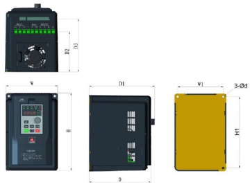
| Модель | H | H1 | W | W1 | D | D1 | D2 | D3 | d |
| 6000-S21R5GB | 180 | 169 | 115 | 105 | 150 | 158 | 85 | 120 | 4.5 |
| 6000-S22R2GB | |||||||||
| 6000-3R75GB/31R5PB | 180 | 169 | 115 | 105 | 150 | 158 | 85 | 120 | 4.5 |
| 6000-31R5GB/32R2PB | |||||||||
| 6000-32R2GB/3004PB | |||||||||
| 6000-3004GB/35R5PB | 195 | 173 | 130 | 108 | 157 | 167 | 100 | 130 | 4.5 |
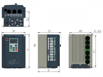
| Модель | H | H1 | W | W1 | D | D1 | D2 | d |
| 6000-35R5GB/37R5PB | 270 | 255 | 190 | 175 | 176 | 186 | 122 | 7 |
| 6000-37R5GB/3011PB |
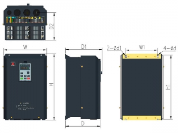
| Модель | H | H1 | W | W1 | D | D1 | D2 | d | d 1 |
| 6000-3011GB/3015PB | 373 | 360 | 235 | 200 | 176 | 188 | 125 | 7 | 12 |
| 6000-3015GB/3018PB | |||||||||
| 6000-3018G/3022P | 420 | 405 | 270 | 200 | 218 | 230 | 175 | 7 | 14 |
| 6000-3022G/3030P | |||||||||
| 6000-3030G/3037P | 503 | 488 | 311 | 200 | 230 | 242 | 180 | 7 | 14 |
| 6000-3037G/3045P | |||||||||
| 6000-3045G/3055P | 590 | 570 | 351 | 200 | 254 | 266 | 192 | 10 | 20 |
| 6000-3055G/3075P | |||||||||
| 6000-3075G/3093P | 698 | 672 | 400 | 280 | 260 | 272 | 186 | 12 | 22 |
| 6000-3093G/3110P | |||||||||
| 6000-3110G/3132P | 850 | 823 | 505 | 420 | 280 | 292 | 212 | 12 | 22 |
| 6000-3132G/3160P |
Установочный размер 380В 160~355кВт трехфазной стандартной модели с основанием
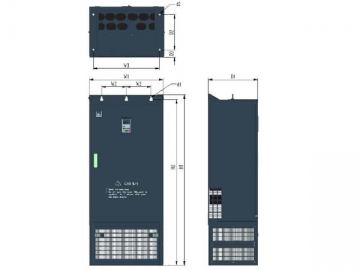
| Модель | W1 | W2 | W3 | H1 | H2 | D1 | D2 | D3 | d 1 | d 2 |
| 6000-3160G/3185P | 600 | 200 | 530 | 1380 | 1360 | 400 | 280 | 60 | 3-φ 14 | 4-φ 14 |
| 6000-3185G/3200P | ||||||||||
| 6000-3200G/3220P | ||||||||||
| 6000-3220G/3250P | ||||||||||
| 6000-3250G/3280P | 800 | 300 | 730 | 1535 | 1515 | 410 | 288 | 60 | 3-φ 14 | 4-φ 14 |
| 6000-3280G/3315P | ||||||||||
| 6000-3315G/3355P | ||||||||||
| 6000-3355G/3400P |
Установочный размер 380В 160~355кВт трехфазной стандартной модели с настенным креплением
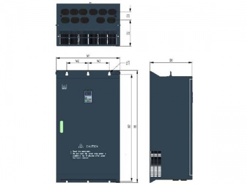
| Модель | W1 | W2 | H1 | H2 | D1 | D2 | D3 | d 1 |
| 6000-3160G/3185P | 600 | 200 | 1026 | 1360 | 400 | 245 | 77 | 6-φ 14 |
| 6000-3185G/3200P | ||||||||
| 6000-3200G/3220P | ||||||||
| 6000-3220G/3250P | ||||||||
| 6000-3250G/3280P | 800 | 300 | 1180 | 1515 | 410 | 250 | 88 | 6-φ 14 |
| 6000-3280G/3315P | ||||||||
| 6000-3315G/3355P | ||||||||
| 6000-3355G/3400P |
Установочный размер 380В 400-500кВт трехфазной стандартной модели
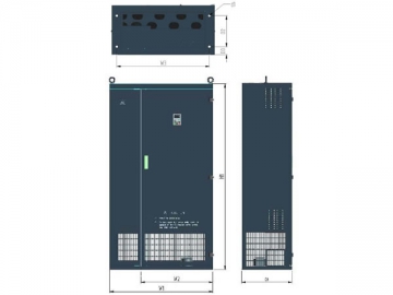
| Модель | W1 | W2 | W3 | H1 | D1 | D2 | D3 | d 1 |
| 6000-3400G | 1000 | 700 | 900 | 1800 | 480 | 300 | 80 | 4-φ 22 |
| 6000-3500G |
Установочный размер 380В 160-500кВт трехфазной модели с узким корпусом
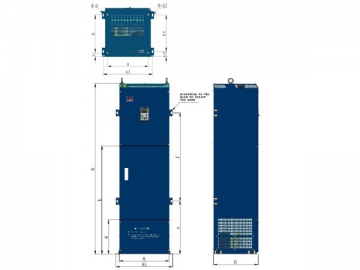
| Модель | W | W1 | D | H | a | b | c | d |
| 6000-3160G/3185P | 450 | 514 | 400 | 1600 | 400 | 315 | 30 | 15 |
| 6000-3185G/3200P | ||||||||
| 6000-3200G/3220P | ||||||||
| 6000-3220G/3250P | ||||||||
| 6000-3250G/3280P | 450 | 514 | 400 | 1800 | 400 | 315 | 30 | 15 |
| 6000-3280G/3315P | ||||||||
| 6000-3315G/3355P | ||||||||
| 6000-3355G/3400P |
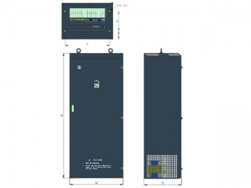
| Модель | W | D | H | a | b | c | d |
| 6000-3400G | 800 | 550 | 2000 | 700 | 300 | 125 | 18 |
| 6000-3500G |
Скачать
Руководство пользователя
ALPHA6000
Брошюра
Электропривод переменного тока серии ALPHA6000 общего назначения
Решения
Применение преобразователя частоты в ALPHA6000 вентиляторах и насосах
Применение инверторов Alpha в термических печах и сталепрокатных станах
План использования инверторов ALPHA в предприятии бумажной промышленности в г. Changping
Применение инвертора Alpha в закалочной печи
Применение инверторов ALPHA6000 в цементной промышленности
Применение инверторов ALPHA в промышленных стиральных машинах
Применение инверторов ALPHA в проекте по сбережению энергии корпорации Fengshou Sugar
Применение инверторов ALPHA в системе центрального кондиционирования воздуха
Применение инвертора ALPHA6000 в станке с ЧПУ
Применение инвертора ALPHA6000 в системе подачи воды
Preface
Thank you for buying ALPHA6000/6100 series inverter made by Shenzhen ALPHA
Inverter Co., Ltd.
To satisfy the high performance needs, ALPHA6000/6100 series inverters use magnetic
flux vector control method to achieve high torque at low speed and low-noise at steady
running. The inner PID operation can perform PID close loop control easily.
ALPHA6000/6100 proprietary features include the advanced automatic torque
compensation, multiple controlling methods, up to 36 fault protections and warning
functions. Online watching and changing parameters, Integrated RS485 Interface, and
operation flexibility. In addition, energy saving running can furthest improves the motor
power factor and efficiency.
ALPHA6000/6100 series are suitable for almost all motor driving applications like
paper process, textile machines, food process, cement, spinning weaving and dyeing,
metallurgy, iron and steel, and other machinery.
The inverter has wide speed-adjusting range, stable operation, high accuracy and reliable
performance. It can be widely used in application of electrical power energy saving.
If you have some problems that can’t be solved in operation, please contact the nearest
local agents or service center, or contact our company directly.
To ensure the perfect use of this product and the safety of user, please read the user
manual carefully before the operation of inverter and keep the manual in proper place for
future reference.
The information contained in this manual is subject to change without notice.
Before mounting, wiring and commissioning the inverter, to ensure the safety of user and
extending the life of this equipment, it strongly suggests that we must read the safety
rules warnings listed in this book and cautions marked on the inverter.
When in operation, we must pay attention to the situation of driven load and all notes that
related on safety.
1
Модератор: тень
-
kU
- Подполковник

- Сообщения: 16308
- Зарегистрирован: 15 окт 2009, 22:05
- Страна: Российская Федерация
- Откуда: Москва

Сообщение
kU » 23 авг 2020, 15:18.
-
Паха46
- Прапорщик
- Сообщения: 2403
- Зарегистрирован: 17 окт 2013, 18:24

Сообщение
Паха46 » 23 авг 2020, 15:55.
Спасибо. Почитаю. Попробую.
——————
Легко умереть за друга,но трудно найти друга готового умереть за тебя..
-
Паха46
- Прапорщик
- Сообщения: 2403
- Зарегистрирован: 17 окт 2013, 18:24
Сообщение
Паха46 » 23 авг 2020, 16:00.
Оно б конечно на словах да пальцем тыкнуть было бы понятней или по телефону.
——————
Легко умереть за друга,но трудно найти друга готового умереть за тебя..
-
Паха46
- Прапорщик
- Сообщения: 2403
- Зарегистрирован: 17 окт 2013, 18:24
Сообщение
Паха46 » 23 авг 2020, 18:41.
Читал,читал и не понял ни чего ![]() .
.
——————
Легко умереть за друга,но трудно найти друга готового умереть за тебя..
-
Змеюка
- Прапорщик
- Сообщения: 2773
- Зарегистрирован: 01 янв 2000, 03:10
Сообщение
Змеюка » 24 авг 2020, 04:01.
Два раза нажимаете PRG
стрелочками находите параметр Р008 — это максимальная частота,
нажимаете SET
поднимаете его стрелочкой с 50 до желаемого (предел 400)
еще раз SET или сразу
два раза PRG
дальше заново то же самое, только параметр 009 ставите в желаемую частоту
Нормальная инструкция на работе, если не получится — пишите, уточню.
-
Паха46
- Прапорщик
- Сообщения: 2403
- Зарегистрирован: 17 окт 2013, 18:24
Сообщение
Паха46 » 24 авг 2020, 08:08.
Змеюка писал(а):
Два раза нажимаете PRG
стрелочками находите параметр Р008 — это максимальная частота,
нажимаете SET
поднимаете его стрелочкой с 50 до желаемого (предел 400)
еще раз SET или сразу
два раза PRG
дальше заново то же самое, только параметр 009 ставите в желаемую частоту
Нормальная инструкция на работе, если не получится — пишите, уточню.
Благодарю.
——————
Легко умереть за друга,но трудно найти друга готового умереть за тебя..
-
Гриня
- Подпоручик
- Сообщения: 3655
- Зарегистрирован: 15 июн 2004, 06:43

Сообщение
Гриня » 24 авг 2020, 12:32.
Был опыт с подобным. С ручки он только 50 гц, выше поднимает только кнопками.
-
Змеюка
- Прапорщик
- Сообщения: 2773
- Зарегистрирован: 01 янв 2000, 03:10
Сообщение
Змеюка » 25 авг 2020, 11:57.
Да, еще что посоветую:
Р006 — «управление с внешних клемм» — ставите в 1.
После чего можно прицепить проводки к клеммам FWD и GND, и на них выключатель около гриндера, при замыкании включится, при размыкании выключится.
Это позволяет убрать преобразователь в коробочку с вентилятором и фильтром от пыли на входе, что сильно продлит его жизнь.
Дальше — Р016 — ставите 20 — 30. Это рост момента при увеличении сопротивления на валу, то есть если придавили со всей силы, гриндер не будет терять скорость.
Если к аппарату подходит кто-то длинноволосый или с неподвернутыми рукавами, и есть опасения про наматывание на вал, то Р018 в наименьшее значение, а в провод к кнопочке от FWD — GND ставите второй выключатель типа грибка под колено или локоть, как аварийный.
P.S. на работе валяется лишняя оригинальная инструкция на английском, как выздоровлю от деревяшки в лицо, могу прислать ее Вам, пишите адрес в личку.
Вернуться в «Мастерская»
Перейти
- Пневматическое оружие
- ↳ Всё о пневматическом оружии
- ↳ Общий
- ↳ ППП
- ↳ PCP
- ↳ PCP online
- ↳ EDgun
- ↳ Компрессионное
- ↳ Углекислый уголок (CO2)
- ↳ Пневматическое оружие глазами владельца
- ↳ Апгрейд и ремонт пневматического оружия
- ↳ Охота с пневматическим оружием
- ↳ Пульки
- ↳ Пострелушки
- ↳ Для начинающих
- ↳ Мастерская
- ↳ Помощь в ремонте и эксплуатации изделий Umarex, Walther, Hammerli Rohm
- ↳ Практическое использование пневматического оружия
- ↳ Общий
- ↳ AirSoft
- ↳ Обзоры
- ↳ Пейнтбол
- ↳ Хардбол
- ↳ Варминт
- ↳ Снайпинг
- ↳ Советы по пулевой стрельбе
- ↳ Продажи
- ↳ Пневматическая барахолка
- ↳ AirSoft
- ↳ Пейнтбол
- ↳ Магазины по пневматическому оружию
- ↳ в России
- ↳ на Украине
- ↳ в Белоруси
- ↳ Другие магазины
- ↳ Запчасти, принадлежности
- Холодное и метательное оружие
- ↳ Холодное оружие
- ↳ Общий
- ↳ Нож глазами владельца
- ↳ Ножи с фиксированым клинком
- ↳ Финки и другие скандинавы
- ↳ Кухонные ножи
- ↳ Специальные ножи и инструмент
- ↳ Складные ножи
- ↳ Неклинковое холодное оружие
- ↳ Клуб любителей Spyderco
- ↳ Для ценителей Спайдерко
- ↳ Samura Knives
- ↳ Китайские ножики
- ↳ Авторские и кастомные ножи
- ↳ Ножевой бой
- ↳ Кают-компания Пятой
- ↳ Метательное оружие
- ↳ Луки и арбалеты
- ↳ Рогатки и пращи
- ↳ Мастерская
- ↳ Инструментальный парк
- ↳ Кузнечное дело
- ↳ Технологии
- ↳ Заточка режущего инструмента
- ↳ Продажи
- ↳ Ножевая барахолка
- ↳ Арбалетно-лучная ярмарка
- ↳ Ножевые магазины
- ↳ Барахолка мастерской
- ↳ Продажа холодного оружия за пределами РФ
- ↳ Частные лица
- ↳ Складные ножи из мастерской
- ↳ Ножи с фиксированным клинком
- ↳ Разовые продажи и обмен складных ножей
- ↳ Разовые продажи и обмен ножей с фиксированным клинком
- ↳ Материалы и оборудование для ножеделов
- Огнестрельное оружие
- ↳ Гладкоствольное оружие
- ↳ Общий
- ↳ Ружье глазами владельца
- ↳ Гладкоствольная мастерская
- ↳ Сайга
- ↳ Клуб любителей МЦ
- ↳ Продукция ИМЗ
- ↳ Снаряжение патронов гладкоствольного оружия
- ↳ Боеприпасы для гладкоствольного оружия
- ↳ Клуб любителей MP-153
- ↳ Benelli Club
- ↳ Комбинированные ружья
- ↳ Куплю-продам ружье
- ↳ Запчасти, принадлежности
- ↳ Купля-продажа Сайга
- ↳ Нарезное оружие
- ↳ Общий
- ↳ Винтовка глазами владельца
- ↳ Боеприпасы для нарезного оружия
- ↳ Продукция КСПЗ
- ↳ Пристрелка оружия
- ↳ Высокоточная стрельба
- ↳ Всё для высокоточной стрельбы
- ↳ Релоадинг
- ↳ Страничка Neckа
- ↳ Специализированные соревнования
- ↳ Легендарные винтовки мировых войн
- ↳ Ремингтон 700 серии
- ↳ Купля-продажа винтовки
- ↳ Оружейная фирма «Орсис»
- ↳ Нарезная барахолка
- ↳ Запчасти, принадлежности
- ↳ Короткоствольное оружие
- ↳ Короткоствольное оружие
- ↳ Пистолет глазами владельца
- ↳ Короткоствол без границ
- ↳ Методика подготовки стрелка
- ↳ Стрелковые туры
- ↳ Стрелковый клуб
- ↳ Продукция Grand Power
- ↳ Продукция ИМЗ
- ↳ Продукция ЗМЗ
- ↳ IDPA
- ↳ По правилам IPSC
- ↳ Легализация короткоствольного оружия
- ↳ Травматическое оружие
- ↳ Общий форум
- ↳ Тюнинг травматического оружия
- ↳ Резинострельное оружие
- ↳ Резинострел глазами владельца
- ↳ Бесствольное оружие
- ↳ Оружие под патрон Флобера
- ↳ «Удар» и все о нем
- ↳ Продукция завода Молот
- ↳ Сигнальное оружие
- ↳ Купля-продажа газового/травмат. оружия
- ↳ Продукция ООО ПКП АКБС
- ↳ РоссИмпортОружие
- ↳ Продукция ЗАО ТЕХНОАРМС
- ↳ Продукция компании «A+A»
- ↳ Клуб любителей турецкого оружия
- ↳ Запчасти
- ↳ Тюнинг и ремонт огнестрельного оружия
- Оптика
- ↳ Оптический форум
- ↳ Общий
- ↳ Оптика глазами владельца
- ↳ Оптика для пневматики
- ↳ Прицелы
- ↳ Оптические прицелы
- ↳ Диоптрические прицелы
- ↳ Коллиматорные прицелы
- ↳ Ночные прицелы
- ↳ Открытые прицелы
- ↳ Другая оптика
- ↳ Дальномеры
- ↳ Подзорные трубы
- ↳ Фонари
- ↳ ЛЦУ
- ↳ Бинокли
- ↳ Ночная оптика
- ↳ Продажи
- ↳ Купля-продажа оптики
- ↳ Купля-продажа ночной оптики
- ↳ Магазины по оптике
- Охота и рыбалка
- ↳ Охота
- ↳ Охота глазами участника
- ↳ Охотничьи товары
- ↳ Охрана природы
- ↳ Подводная охота
- ↳ Трофейная охота
- ↳ Всё об охоте
- ↳ Выживание
- ↳ Изготовление трофеев
- ↳ Охотничьи собаки
- ↳ На охоту
- ↳ О животных
- ↳ Организация охот, клубы, охотничьи хозяйства
- ↳ Оружие на охоте
- ↳ Таксидермия
- ↳ СТИЧ ПРОФИ
- ↳ Горная охота
- ↳ Купля-продажа щенков
- ↳ Снаряжение патронов
- ↳ Птицы
- ↳ Прочие
- ↳ Товары для охотничьих собак
- ↳ На привале
- ↳ Рыбалка
- ↳ Общий
- ↳ Снасти
- ↳ Экипировка
- ↳ Лодки
- ↳ Наживка-приманка-прикормка
- ↳ Кухня
- ↳ Нахлыст
- ↳ Отчёты
- ↳ Соревнования-слёты-турниры
- ↳ Уловы
- ↳ Полезные приблуды
- ↳ Рыбацкие хитрости
- ↳ Куда поехать на рыбалку
- ↳ Спининг
- ↳ Троллинг
- ↳ Зимняя рыбалка
- ↳ Подводная охота
- ↳ Курьёзы
- ↳ Рыболовная барахолка
- Спортивная стрельба
- ↳ Спортивная стрельба из нарезного оружия
- ↳ Специализированные соревнования
- ↳ ISSF — Пулевая стрельба
- ↳ IPSC
- ↳ IDPA
- ↳ Стрелковый клуб «Объект»
- ↳ Стрелковый клуб «Мишень»
- ↳ Товары для спортивной стрельбы
- ↳ Спортивная стрельба из пневматического оружия
- ↳ БР
- ↳ ФТ/ХФТ
- ↳ Оборудование для Бенчреста
- ↳ Спортивная стрельба из пневматики
- ↳ Стрельба из гладкоствольного оружия
- ↳ Стендовая стрельба
- ↳ Пулевая стрельба из гладкоствольного оружия
- Безопасность
- ↳ Безопасное обращение с оружием
- ↳ Безопасность с пневматическим оружием
- ↳ Безопасность с огнестрельным оружием
- ↳ Безопасность с травматическим оружием
- ↳ Безопасность с холодным оружием
- ↳ Безопасность для рыболова
- ↳ Безопасность для мастеровых
- ↳ Пожарная безопасность
- ↳ Общая безопасность
- Военное дело и гражданская оборона
- ↳ Военное дело
- ↳ Авиация
- ↳ Армейский раздел
- ↳ Тактическое оружие
- ↳ Артиллерия
- ↳ Баллистика
- ↳ История оружия
- ↳ ПВО
- ↳ Поиск однополчан
- ↳ Давай закурим!
- ↳ Гражданская оборона
- ↳ Гражданская оборона
- ↳ Самооборона в России
- ↳ Самооборона без оружия
- ↳ Охранная деятельность
- ↳ Технические средства охраны
- ↳ Обмундирование, экипировка, амуниция
- ↳ Выживание в кризисных ситуациях
- ↳ Экипировка своими руками
- ↳ Организация владельцев гражданского оружия
- ↳ Продукция компании «СПЛАВ»
- ↳ Магазины амуниции и экипировки
- ↳ Купля-продажа экипировки
- ↳ Газовое оружие
- ↳ Газовые баллончики
- ↳ Газовые пистолеты и револьверы
- ↳ Тюнинг газового оружия
- ↳ Электрошоковые устройства
- ↳ Гражданское оружие
- ↳ Разовые продажи и обмен экипировки
- История оружия
- ↳ Коллекционное оружие
- ↳ Антиквариат
- ↳ Историческое холодное оружие
- ↳ Макеты и реплики оружия
- ↳ Обладателям коллекционных лицензий
- ↳ Японское холодное историческое оружие
- ↳ Дульнозарядное оружие
- ↳ Реплики холодного оружия
- ↳ Мастерская коллекционного оружия
- ↳ Документация по оружию
- ↳ Оружейные идеи
- ↳ Военно-исторические миниатюры
- ↳ Компьютерное моделирование оружия
- ↳ Популярная механика
- ↳ Книжная барахолка
- ↳ Купля-продажа
- ↳ Купля-продажа антиквариата
- ↳ Купля-продажа макетов, реплик
- Обо всем
- ↳ Радиосвязь
- ↳ Новости
- ↳ Правила раздела
- ↳ Пожелания покупателей
- ↳ Портативные рации
- ↳ Производители радиостанций
- ↳ Anytone
- ↳ Baofeng
- ↳ Kydera
- ↳ Boxchip
- ↳ Puxing
- ↳ Quansheng
- ↳ Tytera
- ↳ VOYAGER
- ↳ WLN
- ↳ WOUXUN
- ↳ Yiyan
- ↳ Автомобильные рации
- ↳ Baofeng
- ↳ Cobra
- ↳ Resent
- ↳ TYT
- ↳ Tytera
- ↳ VOYAGER
- ↳ Yiyan
- ↳ LPD, PMR, FRS
- ↳ CB Radio 27МГц
- ↳ Цифровые рации
- ↳ Антенны для раций
- ↳ Производители антенн
- ↳ Baofeng
- ↳ Comet
- ↳ Cte
- ↳ Diamond
- ↳ Kenwood
- ↳ Lemm
- ↳ Nagoya
- ↳ Opek
- ↳ Storm
- ↳ Аксессуары к рациям
- ↳ Батареи для раций
- ↳ Зарядные устройства
- ↳ Программаторы
- ↳ Блоки питания
- ↳ Измерительные приборы
- ↳ Гаджеты
- ↳ Разъемы и переходники
- ↳ Ретрансляторы
- ↳ Гарнитуры, наушники, тангенты
- ↳ Защитные чехлы
- ↳ Некондиция и б.у.
- ↳ Купля-продажа электронных устройств
- ↳ Разное
- ↳ Спутниковые телефоны
- ↳ Приёмники
- ↳ Сотовые телефоны
- ↳ GPS-навигаторы
- ↳ Коммуникаторы
- ↳ Карманные компьютеры
- ↳ Купля-продажа средств навигации
- ↳ Отдел заказов
- ↳ Заказы оружия
- ↳ Заказы ножей
- ↳ Заказы оптики
- ↳ Заказы по охоте и рыбалке
- ↳ Заказы антиквариата
- ↳ Заказы других товаров
- ↳ Книга отзывов
- ↳ Транспортный раздел
- ↳ Полноприводные автомобили
- ↳ Мотоциклы
- ↳ Купля продажа транспорта и запчастей
- ↳ Дорожно-транспортные происшествия
- ↳ Купля-продажа автомобилей
- ↳ Купля-продажа мотоциклов и т.п.
- ↳ Купля-продажа водного транспорта
- ↳ Разное
- ↳ Частные объявления
- ↳ Домашнее хозяйство
- ↳ Поиск работы
- ↳ Спорт
- ↳ Компьютерные игры
- ↳ Компьютеры и программы
- ↳ Мобильные измерительные приборы
- ↳ Фонари
- ↳ Фонарная барахолка
- ↳ Сельхозпродукция и продукция охоты
- ↳ Медицина
- ↳ Бизнес-Клуб
- ↳ Литература и языкознание
- ↳ Мемориал
- ↳ Криминальные сводки
- ↳ Подарю
- ↳ Юмор
- ↳ Законодательство
- ↳ Законодательство
- ↳ Правовая поддержка
- ↳ Законодательство об охоте
- ↳ Оружие в СМИ
- ↳ Клуб работников правоохранительных органов
- ↳ Общение
- ↳ Организация встреч
- ↳ Знакомства
- ↳ Мужской разговор
- ↳ Отчеты, истории, куда пойти
- ↳ Отдых, путешествия
- ↳ Фотография
- ↳ Отзывы о продавцах и покупателях
- ↳ Курилка
- Регионы
- ↳ Российская Федерация
- ↳ Центральный округ
- ↳ Москва
- ↳ Белгород
- ↳ Брянск
- ↳ Владимир
- ↳ Воронеж
- ↳ Вологда
- ↳ Калуга
- ↳ Коломна
- ↳ Курск
- ↳ Липецк
- ↳ Рязань
- ↳ Тамбов
- ↳ Тверь
- ↳ Тула
- ↳ Ярославль
- ↳ Северо-Западный округ
- ↳ Санкт-Петербург
- ↳ Купля-продажа. Санкт-Петербург
- ↳ Архангельск
- ↳ Карелия
- ↳ Калининград
- ↳ Мурманск
- ↳ Псков
- ↳ Южный округ
- ↳ Волгоград
- ↳ Краснодар
- ↳ Ростов
- ↳ Ставрополь
- ↳ Приволжский округ
- ↳ Башкортостан
- ↳ Ижевск
- ↳ Йошкар-Ола
- ↳ Киров
- ↳ Нижний Новгород
- ↳ Оренбург
- ↳ Пенза
- ↳ Пермь
- ↳ Самара
- ↳ Саратов
- ↳ Татарстан
- ↳ Ульяновск
- ↳ Уральский округ
- ↳ Екатеринбург
- ↳ Стрелковый клуб Южного Урала
- ↳ Тюмень
- ↳ Челябинск
- ↳ Сибирский округ
- ↳ Барнаул
- ↳ Иркутск
- ↳ Кемерово
- ↳ Красноярск
- ↳ Новокузнецк
- ↳ Новосибирск
- ↳ Омск
- ↳ Дальний Восток
- ↳ Владивосток
- ↳ Томск
- ↳ Хабаровск
- ↳ Чита
- ↳ Другие страны
- ↳ Украина
- ↳ Купля-продажа. Украина
- ↳ Киев
- ↳ Беларусь
- ↳ Минск
- ↳ Казахстан
- ↳ Алма-Ата
- ↳ Молдова
- ↳ Германия
- ↳ Армения
- ↳ Латвия
- ↳ Литва
- ↳ Эстония
- ↳ Другие страны
- О нашем сайте
- ↳ Информация о нашем сайте
- ↳ О сайте
- ↳ ТОП-новости
- ↳ Новости и объявление
- ↳ Референдумы
- ↳ Книга жалоб
- ↳ Ссылки

Кто сейчас на конференции
Сейчас этот форум просматривают: нет зарегистрированных пользователей и 4 гостя
Specifications:
|
Accompanying Data:
Alpha 6000 Inverter PDF Operation & User’s Manual (Updated: Saturday 18th of February 2023 09:53:36 AM)
Rating: 4.9 (rated by 47 users)
Compatible devices: ALUTILE, 6000S series, ALPHA6000 Series, SMILE5, FR-A8NC, SA-600R Series, C350 Series, L600W.
Recommended Documentation:
Alpha 6000: Text of Operation & User’s Manual
(Ocr-Read Version Summary of Contents, UPD: 18 February 2023)
-
108, Chapter 5 Parameter Introductions 107 37, 38:External fault normally open/normally closed; 54, 55: EH2 External fault rising edge valid/falling edge valid EH0 External fault normally open, EH1External fault normally closed; EH2 External fault rising edge valid, EH3 External fault falling edge valid: External fault instruction. Fault instruction from devices associated with inverters …
-
129, Chapter 5 Parameter Introductions 128 P6.02 Preset of wobble frequency Range: 3004GB/35R5PB and below: 0.00~650.0Hz 【0.00Hz】 35R5GB/37R5PB and above: 0.00~400.0Hz 【0.00Hz】 P6.03 Holding time before wobble frequency operating Range: 0.0~3600s【0.0s】 P6.04 Wobble frequency amplitude Range: (0.0~50%) of P0.00 【0.0%】 P6.05 Skip frequency Range: (0…
-
170, Chapter6 Troubleshooting 169 Table 6-2 Warning display and description Warning display Display content Description Uu Under voltage detection Detected under voltage, the inverter can continue working after detected OLP2 Warning of the inverter’s overload beforehand The inverter working current exceeded overload detection level and maintained a longer time than the setting of…
-
58, Chapter 4 Parameter Index 57 Function code Function Name Range of settings Default Change MODBUS Address P1.07 Time of S-curve rising 10.0~80.0% (Acc/Dec Time) P1.06+P1.07≤90% 60.0% ○ 0207 P1.08 Stop mode 0: Deceleration to stop 1: Coast to stop 2: Dec +DC braking 0 × 0208 P1.09 DC injection braking frequency at stop 0.00~MIN(50.00Hz, Frequency upper limi…
-
198, Appendix3 Main Circuit Output Cable Selection (Recommended) 197 Voltage (V) Power grade(kW) Wire gauge(mm 2 ) The maximal length of output cable(m) Without output reactor With output reactor No Shielded Cable ( m) Shielded Cable (m) No Shielded Cable (m) Shielded Cable (m) 380 280kW 185*2 320 280 550 430 315kW 250*2 320 280 550 430 355kW 325*2 320 280 550 …
-
59, Chapter 4 Parameter Index 58 P2: Auxiliary Operation Function code Function Name Range of settings Default Change MODBUS Address P2.00 Jog frequency 0.10~Upper limit frequency 5.00Hz ○ 0300 P2.01 Acc time of Jog 3132G/3160P or below: 0.1~3600s 3160G/3185P or above: 1.0~3600s 3022G/3030P or below: 6.0s 3030G/3037P or above: 20.0s ○ 0301 P2.02 Dec ti…
-
142, Chapter 5 Parameter Introductions 141 voltage will keep constant within the inverter output capacity. P9.08 Over modulation enable Range: 0, 1【0】 0: Disabled 1: Enabled Note: When the over modulation function is enabled, the inverter voltage output capacity can be improved. However, if the output voltage is too high, the output current harmonics will increase. P9.09…
-
151, Chapter 5 Parameter Introductions 150 X3 X5 X7 X8X6X4X2X1 Y1 Relay1 TA/TB/TC Relay2 BRA/BRB/BRC Y2DO Always on Fig. 5-12-2Terminal status diagram of 35R5GB/37R5PB~3500G PC.19 Actual length (m) Range: 0,1【0】 0: No display 1: Display Note: If PC.19 is set to 1, the actual length will be displayed in monitoring state, and all unit indicators will be off. If it is se…
-
92, Chapter 5 Parameter Introductions 91 P1.11 DC injection braking current at stop Range: This value depends on the inverter model【0.0%】 P1.12 DC injection braking time at stop Range: 0.0~30.0s【0.0s】 Note: DC injection braking is injecting DC current to motor, to let it stop quickly, and keep the spindle of motor in standstill until finished DC injection braking O…
-
125, Chapter 5 Parameter Introductions 124 2: Continue to operate at the frequency when the inverter stops Note: Restart from first stage If the inverter stops during PLC operation because of receiving stop command or fault, or power loss, it will restart from the first step after restarting. Continue from the step where the inverter stops When the inverter stops…
-
77, Chapter 4 Parameter Index 76 Function code Function Name Range of settings Default Change MODBUS Address Pd.09 Input phase loss detection delay time 2~255s 10s × 0E09 Pd.10 Output phase loss detection level (SP0) (Motor rated current corresponds to 100%) 0~100% 2% × 0E0A Reserved (S2R4GB, S2R75GB) Pd.11 Output phase loss detection delay …
-
163, Chapter 5 Parameter Introductions 162 If PF.03 is set to 3, the rated parameters stored in the keyboard except motor’s will be cope to inverter. Tips: When inverter is working in the same application, using this function can quickly copy the set parameters, and shorten the time spent on debugging and maintenance. PF.03 is only valid f…
Alpha 6000: Recommended Instructions
C.valve C Class, DAV-S300 — Dvd Dream System, 386SX, 7FF1CME


-
形3G3JX-A□簡易型小型インバータNT302E0193670-5Cマニュアル番号マニュアル名称取扱説明書このたびは、SYSDRIVE 形 3G3JX シリーズをお買い求めいただきまして、誠にありがとうございます。この製品を安全に正しくご使用いただくために、お使いになる前に、この取扱説明書と安全上 …
3G3JX-AE002 4
-
/ Perfect Charging / Perfect Welding / Solar Energy42,0410,2145 012-04082017Fronius Symo HybridInstallationInstallation InstructionGrid-connected inverterwww.fronius-usa.com/inverter-manuals FIND YOUR OPERATING MANUALSwww.fronius.com/energy-package-manuals FIND YOUR OPERATING MANUALS …
Symo Hybrid 52
-
FR-A700INSTALLATION GUIDELINEFR-A720-00030 to 03460-NAFR-A740-00015 to 09620-NAFR-A720-00030 to 00330-N4FR-A740-00015 to 00170-N4FR-A760-00017 to 06630-NAINVERTER700CONTENTSINSTALLATION OF THE INVERTER AND INSTRUCTIONS…………….. 1OUTLINE DIMENSION DRAWING ………………………………………………… 3WIRING…………………………………………………. …
FR-A700 45
-
E6582062Safety precautionsIIntroductionIIQuick indexIIIRead first1Installation and wiring2[Basic operation] Operation panel and screen display3[Basic operation] Operation methods of motor4[Fundamental opera-tion] How to use parameters5[Advanced] How to use parameters6Operating using exter-nal signals7Monitoring operation status8Measures to satisfy standards9Selection and installa-tion of perip …
TOSVERT VF-AS3 598
-
PNI L500WPower inverter / Invertor de tensiune / Tápegység / Falownik / Inversor de energia / Invertitore di potenzaUser manual / Manual de utilizare Használati utasítás / Instrukcja obsługi Manual de usuario / Manuale dell’utente …
L500W 8
-
Januar 2010 Ver08208 962-21 (208 962-E8) · 12/2010 · pdfTechnical ManualInverter Systemsand Motorsfor the Contouring ControlsTNC 410 MTNC 426 MTNC 430 MiTNC 530MANUALplusMMANUALplus 4110CNC PILOT 4290 …
TNC 410 M 700
-
PGC — 2/20/01 Page 1 of 1Hitachi America, Ltd.EN-022001-1ENGINEERING NOTESUBJECT: J100 AND J300 WATT LOSS DATAAt 100% Load:Model Watt Loss (W) CarrierFrequency(kHz)J100-004SF 40 16J100-007SF 65 16J100-015SF 75 16J100-022SF 110 16J100-015HF 100 16J100-022HF 135 16J300-037HF 208 16J300-055HF 370 16J300-075HF 450 16J300-110HF 610 16J300-150HF 810 16J300-220HF 800 12J300-300HF 1100 10J300-370HF …
J300 Series 1
-
AT‐MG250 User Manual – V1.02 AT‐MG250Micro‐inverterInstallationManualApxteckRenewableTechnologyCo.,Ltd. …
AT?MG250 16