- Manuals
- Brands
- Holip Manuals
- Inverter
- HLP-A Series
- Instruction manual
-
Contents
-
Table of Contents
-
Troubleshooting
-
Bookmarks
Quick Links
Related Manuals for Holip HLP-A Series
Summary of Contents for Holip HLP-A Series
-
Page 2
HLP-A Series… -
Page 4: Table Of Contents
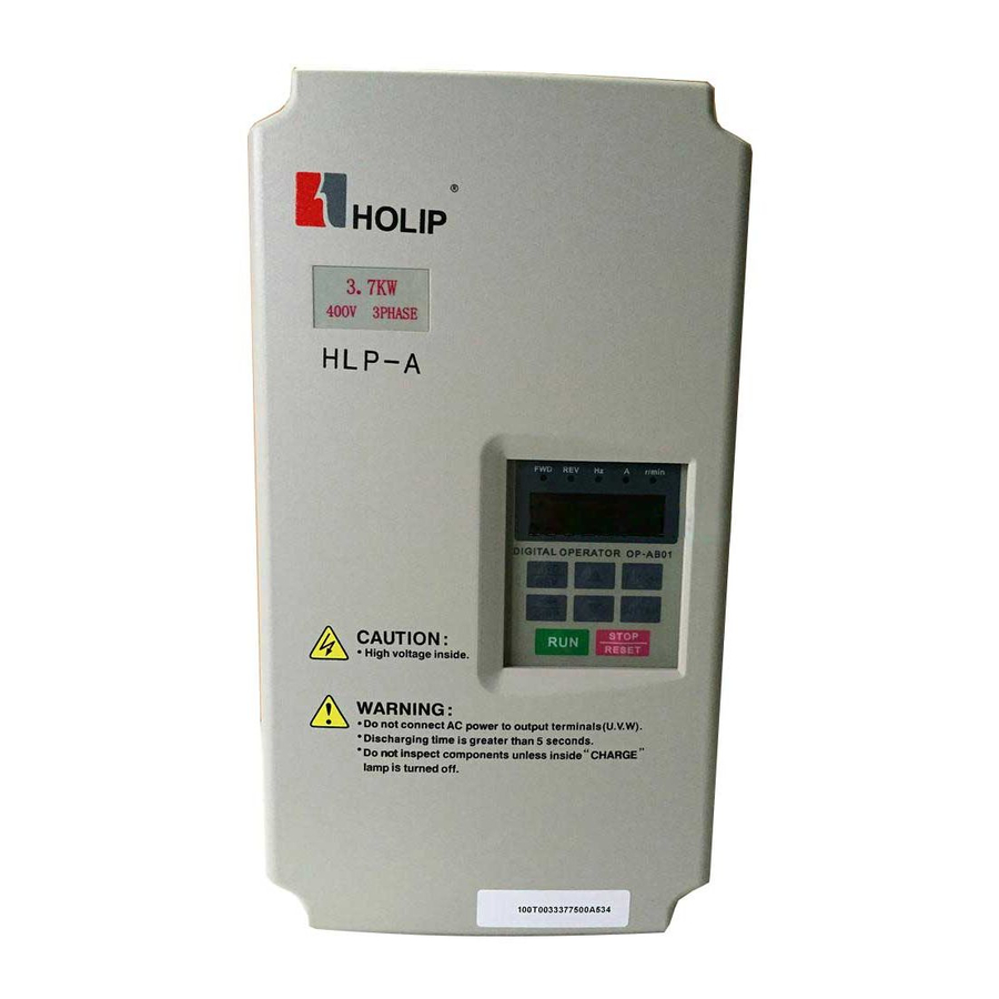
HLP-A Series I. Introduction 1. Checks upon Delivery 2. Nameplate Description of HLP Series Inverter II. Safety Precautions 1. Before the Power-up 2. During the Power-up 3. During the Operation III. Standards and Specifications 1. Particular Specifications 2. General Specifications IV.
-
Page 5: Table Of Contents
HLP-A Series X. Care & Maintenance, Fault Information and Troubleshooting 82 1. Precautions about Inspection and Maintenance 2. Periodical Inspection and Maintenance items 3. Fault Indication and Troubleshooting 4. Faults and Analysis XI. Selection of Peripheral Devices and Disposition 1. Options 2.
-
Page 6: I. Introduction
HLP-A Series I. Introduction Thank you for purchasing and using the general-purpose inverter of HLP series of multi-functions and high performance. Please read carefully the operation manual before putting the inverter to use so as to correctly install and operate the inverter, give full play to its functions and ensure the safety.
-
Page 7: Checks Upon Delivery
HLP-A Series Caution ● Do not make any voltage-withstanding test with any component inside the inverter. These semi-conductor parts are subject to the damage of high voltage. ● Never connect the AC main circuit power supply to the output terminals U.V W of the inverter.
-
Page 8: Nameplate Description Of Hlp Series Inverter
HLP-A Series 2. Nameplate Description of HLP Series Inverter MODEL: Model: HLP A 01D5 43 C Hardware Version Voltage Rating,43 means 3-phase 380V Inverter Capacity,01D5 means 1.5KW Serial No., A means A series Trade Mark HLP-A Series…
-
Page 9: Ii. Safety Precautions
HLP-A Series II. Safety Precautions 1. Before the Power-up Caution ● Check to be sure that the voltage of the main circuit AC power supply matches the input voltage of the inverter. ● The symbol, , represents ground terminals. Be sure to make correct ground connection of the earth terminals of the motor and the inverter for safety.
-
Page 10
HLP-A Series ● Be su re to t u r n off the power supply before dissembling or assembling the operation keypanel and fixing the front cover to avoid bad contact causing faults or non-display of the operator. ● Do not install the inverter in a space with explosive gas to avoid the risk of explosion. -
Page 11: During The Power-Up
50Hz. The user must strictly follow the instruction to operate and make wire connection. Otherwise HOLIP will not responsible for the damages due to wrong operation. The user will responsible for the damages themselves.
-
Page 12: Particular Specifications
HLP-A Series III. Standards and Specifications 1. Particular Specifications Inverter Output Suitable Input Power Type Capacity Current Motor Voltage (KW) (KVA) (KW) One & Three phase HLPA00D423C 220V 50Hz One & Three phase HLPA0D7523C 0.75 0.75 220V 50Hz One & Three phase…
-
Page 13
HLP-A Series Inverter Output Suitable Input Power Type Capacity Current Motor Voltage (KW) (KVA) (KW) One & Three phase HLPA009023B 137.2 220V 50Hz HLPA0D7543C 3Φ380V 50Hz 0.75 0.75 HLPA01D543C 3Φ380V 50Hz HLPA02D243C 3Φ380V 50Hz HLPA03D743B 3Φ380V 50Hz HLPA05D543B 3Φ380V 50Hz 12.5… -
Page 14: General Specifications
HLP-A Series 2. General Specifications Inverter Series HLP-A Control Mode SPWM 380±15% for 380V power ; 220±15% Input Power for 220V power D i s p l a y i n g f r e q u e n c y, c u r r e n t , 5-Digits Display &…
-
Page 15
HLP-A Series 5 multi-function output terminals for displaying of r unning, zero speed, Multi-Outputs counter, external abnormity, program operation and other information and warnings. AV R (a u t o v o l t a g e r e g u l a t i o n) ,… -
Page 16: Iv. Storage And Installation
HLP-A Series IV. Storage and Installation 1. Storage The inverter must be kept in its original package box before installation. Pay attention to the followings when keeping it in storage if the inverter is not used for the time being: ●…
-
Page 17
HLP-A Series board under the inverter bottom base and install it again. If the inverter is installed on a loose surface, stress may cause damage of parts in the main circuit so as to damage the inverter. ● The inverter should be installed on non-combustible materials, such as iron plate. -
Page 18: V. Wiring
HLP-A Series V. Wiring 1. Main Circuit Wiring Schematic Diagram Power supply: ● Verify that the inverter’s rated voltage coincides with AC power supply voltage to avoid a damage of the inverter No fuse breaker: ● Refer to the related list Ground fault circuit interrupter: ●…
-
Page 19: Description Of Terminal Block
HLP-A Series 2. Description of Terminal Block 1 ) Arrangement of Main circuit Terminals HLPA00D423C-HLPA01D523C HLPA0D7543C-HLPA02D243C HLPA03D743B HLPA02D223B-HLPA03D723B HLPA05D543B-HLPA07D543B HLPA001143B-HLPA003043B HLPA05D523B-HLPA003023B HLPA003743B-HLPA016043B HLPA003723B-HLPA009023B Cabinet HLPA013243BG-HLPA041543B HLP-A Series…
-
Page 20
HLP-A Series 2) Arrangement of Control Circuit Terminals HLPA00D423C-HLPA01D523C HLPA0D7543C-HLPA02D243C HLPA03D743B-HLPA041543B HLPA001123B-HLPA009023B HLPA02D223B-HLPA03D723B HLPA05D523B-HLPA07D523B 3) Function Description of Main circuit Terminals Symbol Function Description Input terminal of AC line power. ( 220V class, for both R.S.T single/three phase, single phase connected to any two phases )… -
Page 21: Basic Connection Diagram
HLP-A Series Symbol Function Description Factory setting M a x . o u t p u t c u r r e n t +12V Power Supply 200mA M a x . o u t p u t c u r r e n t…
-
Page 22
HLP-A Series 12V/100mA HLPA00D423C-HLPA03D723B HLPA0D7543C-HLPA03D743B HLPA05D543B-HLPA07D543B HLP-A Series… -
Page 23
HLP-A Series EV(P24) HLPA001143B~HLPA003043B HLPA05D523B~HLPA003023B HLPA003743B~HLPA041543B HLPA003723B~HLPA009023B HLP-A Series… -
Page 24: Precautions On Wiring
HLP-A Series 4. Precautions on Wiring 1) For the main circuit wiring: ● While wiring the sizes and specifications of wires should be selected and the wiring should be executed according to the electrical engineering regulations to ensure the safety.
-
Page 25
HLP-A Series Control Input wire Output wire Model NFB(A) wire Screw HLPA07D523B HLPA001123B HLPA001523B HLPA18D523B HLPA002223B HLPA003023B HLPA004523B HLPA005523B HLPA007523B HLPA009023B HLPA0D7543C HLPA01D543C HLPA02D243C HLPA03D743B HLPA05D543B HLPA07D543B HLPA001143B HLPA001543B HLPA18D543B HLPA002243B HLPA003043B HLPA003743B HLPA004543B HLPA005543B HLPA007543B HLPA009043B HLPA011043B HLPA013243B HLPA016043B… -
Page 26
HLP-A Series Control NFB(A) Input wire Output wire Model wire Screw HLPA022043B 150×2 150×2 HLPA025043B 150×2 150×2 HLPA028043B 150×2 150×2 HLPA030043B 150×2 150×2 HLPA031543B 1000 185×2 150×2 HLPA034543B 1000 185×2 150×2 HLPA037543B 1200 240×2 185×2 HLPA040043B 1200 240×2 185×2 HLPA041543B 1200 240×2… -
Page 27
HLP-A Series (1) Good (2) Good (3) Not good HLP-A Series… -
Page 28: Vi.instruction Of The Digital Operator
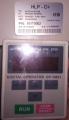
HLP-A Series VI. Instruction of the Digital Operator 1. Description of the Digital Operator Note: The inverter of the hardware version C can use the panel OP-AC01,the inverter of the hardware version B can use the panel OP-AB01 or OP- AB02.
-
Page 29: Description Of The Panel Type
HLP-A Series 2. Description of the panel type 3. List of the panel used in inverter Model Specification Panel type HLPA00D423C 0.4KW/220V OP-AC01 HLPA0D7523C 0.75KW/220V OP-AC01 HLPA01D523C 1.5KW/220V OP-AC01 HLPA02D223B 2.2KW/220V OP-AB01 HLPA03D723B 3.7KW/220V OP-AB01 HLPA05D523B 5.5KW/220V OP-AB02 HLPA009023B 90KW/220V HLPA0D7543C 0.75KW/380V…
-
Page 30: Description Of Operation Examples
HLP-A Series 2) Description of Display Items 5. Description of Operation Examples Indicator Procedures Display Explanation Lamp Power up Dsp2.0 FWD Hz Self detect when power-up, ↓ AXX.XX ¢ ¤ display version no. display ← running f requency PROG CD000…
-
Page 31
HLP-A Series Indicator Procedures Display Explanation Lamp ↓ FWD Hz Switch to main screen, display running DISP 50.00 ¤ ¤ f requency Switch of FWD.REV.rotation, display the ↓ 50.00→ 00.00 REV Hz status of REV.rotation → 50.00 ¤ ¤ ↓… -
Page 32: Vii. Commissioning
HLP-A Series VII. Commissioning 1. Important Checks before the Commissioning ● If there is any wrong connected wires? Pay special attention to the terminal of U.V.W; Make sure the power supply wires are connected to R.S.T, not U.V.W. ● If there is any metal powder or wires left on the base plate of the inverter or the terminal block, which may cause short circuit.
-
Page 33: Parameter And Function List
HLP-A Series VIII. Function List Parameter and Function List (Part 1) Set Range & Function Factory Category Code Function Explanation Setting CD000 Main Frequency 0.00~400.00 Hz 0.00 CD001 Max. Voltage 0.1V—* 220/380 CD002 Base Frequency 0.01~400.00 Hz 50.00 CD003 Intermediate Voltage 0.1V—*…
-
Page 34
HLP-A Series Parameter and Function List (Part 2) Set Range & Function Factory Category Code Function Explanation Setting 0: Rev Run forbidden; CD037 Rev. Rotation Select 1: Rev Run Enable 0: STOP Invalid CD038 STOP key select 1: STOP Valid CD039 S-Curve Time 0.0~6500.0S… -
Page 35
HLP-A Series Parameter and Function List (Part 3) Set Range & Function Factory Category Code Function Explanation Setting *CD056 Multi-output 1(DRV) 0: Invalid; 1: Run; 2: Fault indication; *CD057 Multi-output 2(UPF) 3: Zero Speed; Multi-output 4: Braking indication; *CD058 3(Terminals of 5: Set Frequency reach;… -
Page 36
HLP-A Series Parameter and Function List (Part 4) Set Range & Function Factory Category Code Function Explanation Setting Bias Direction at 0: Positive direction CD069 Higher Frequency 1: Negative direction Analog Negative Bias 0:Not allowable CD070 Reversed 1:Allowable AM Analog output… -
Page 37
HLP-A Series Parameter and Function List (Part 5) Set Range & Function Factory Category Code Function Explanation Setting CD095 AutoPLC Memory CD096 Reserved CD109 Number of Auxiliary CD110 Pump Continuous CD111 Operating Time of 1~9000min Aux.Pumps Interlocking Time of CD112 0.1~250S… -
Page 38
HLP-A Series Parameter and Function List (Part 6) Set Range & Function Factory Category Code Function Explanation Setting Set according to Motor CD130 Rated Motor Voltage nameplate Set according to Motor CD131 Rated Motor Current nameplate CD132 Motor pole number. -
Page 39
HLP-A Series Parameter and Function List (Part 7) Set Range & Function Factory Category Code Function Explanation Setting Communication Baud CD161 Rate Communication Data CD162 Method CD163 Reserved CD166 CD167 Display Items 0-31 CD168 Display Items Open Voltage Rating of… -
Page 40: Ix. Descriptions Of Functions
HLP-A Series IX. Descriptions of Functions CD000 Main Frequency Set Range: 0.00-400.00 Hz Unit: 0.01 Hz Factory Setting: 0.00 In the digital operator mode, the inverter will run at the set value of CD000. During running, the operating f requency can be changed by pressing ▲ or ▼ .
-
Page 41
HLP-A Series f requency the torque compensation will lose its f unction. When adjusting this parameter the output current of the inverter should be increased f rom low to high slowly according to the load of machines until it meets the starting requirement. -
Page 42
HLP-A Series Code Code CD003 CD005 CD012 CD013 CD035 CD003 CD005 CD012 CD013 CD035 Model Model A007523B A022043B A009023B A025043B A0D7543C A028043B A01D543C A030043B A02D243C 10.5 A03 1543B A03D743B 10.5 A034543B A05D543B A037543B A07D543B A040043B A041543B Note: ① Ramp Time 2 = Ramp Time 1 x 2 ②… -
Page 43
HLP-A Series This is set for preventing workers f rom false operation to avoid over-heat or some other mechanical faults, which might be caused due to too low operating f requency. The setting of Frequency Lower Limit must be less than the set value of CD007. -
Page 44
0Hz (See t2 in the diagram). HLP-A Series inverter have altogether 4 Ramp Times. For Ramp Time 2.3.4 the user can select the different ramp up or down time through the external terminals or switching of ramp time according to the actual needs. -
Page 45
HLP-A Series speed. When restarting, the current becomes higher, and over-current or stall may occur. So attention must be paid to the adjustment of current level of f requency track. Generally, CD144 is adjusted around 100. The concrete value can be set according to the characteristics of mechanical load. -
Page 46
HLP-A Series CD034 Source of Operating Frequency Set Range: 0—2 Unit: 1 Factory Setting: 0 0: Set by the operator. Operating f requency is given via the digital operator. 1 : Set by external terminals. Operating f requency is controlled by analog signals input via external terminals. -
Page 47
HLP-A Series is set by Ramp-up Time 4. When the jog button is released the inverter will stop output immediately. In case of jogging f unction please set the corresponding multi-input terminals to 07 or 08. This f unction is only valid at stop. It is invalid at running. For the related parameters refer to CD050-CD055. -
Page 48
HLP-A Series CD040 Up/Down Set Range: 0.01~2.50Hz Unit:0.01Hz Factory Setting:0.01 This parameter can be set in combination with CD073 for Up/Down of external control and the speed of increase and decrease. the step length of Up/Down=(the set value of CD040/0.01)× UP/DOWN speed CD041 Starting Frequency Set Range: 0.10—10.00 Hz… -
Page 49
HLP-A Series CD044 Skip Frequency 1 CD045 Skip Frequency 2 CD046 Skip Frequency 3 Set Range: 0.00—400.00 Hz Unit: 0.01Hz Factory Setting: 0.00 CD047 Skip Frequency Range Set Range: 0.10—10.00 Hz Unit: 0.01Hz Factory Setting: 0.50 These three f requency skipping points are set for avoiding a mechanical resonance point. -
Page 50
HLP-A Series CD050 Multi-input 1 (FOR function) Factory Setting: 02 CD051 Multi-input 2 (REV function) Factory Setting: 03 CD052 Multi-input 3 (RST function) Factory Setting: 10 CD053 Multi-input 4 (SPH function) Factory Setting: 17 CD054 Multi-input 5 (SPM function) Factory Setting: 18… -
Page 51
HLP-A Series of the inverter will be increased or decreased by one unit. When the switch of the terminal is hold the f requency will increase or decrease rapidly to a point and then increase or decrease 26: Down Function at even speed. When the power is up again af ter the power breakdown the changed f requency will not be memorized. -
Page 52
HLP-A Series 3. Description of Ramp Time 1 and 2: 1) This f unction is only valid when CD076 is set to 0, 1 and 2. Under the disturbance and internal control multi-speed it is invalid. 2) Any two multi-inputs can be combined for 4 kinds of ramp time for selection. -
Page 53
HLP-A Series Note: ( 1 ) This f unction is only valid when CD076 is set to 1, i.e. for 4-Speed of external control. ( 2 ) Low, middle and high speed f requency are determined by Frequency 2,3, 4. -
Page 54
HLP-A Series ( 8 ) When using the f unction of UP and DOWN, the keys of △ ▽ of the panel are valid. Af ter changing the values it needs to press SET (ENTER) key for confirmation and then the inverter can implement the action. Meanwhile the value will write to CD000, which will be memorized af ter a power breakdown. -
Page 55
HLP-A Series 02: Fault Indication: The contact will act when the inverter detects abnormal conditions. 03: Zero Speed: The contact will act when the output f requency of the inverter is less than its starting f requency. 04: DC Braking indication: The contact will act when the inverter is in DC braking. -
Page 56
HLP-A Series 28: PID Lower Limit Alarm: This contact will act when the PID feedback is smaller than the lower limit (the set value of CD156). 29: PID Upper Limit Alarm: This contact will act when the PID feedback is greater than the upper limit (the set value of CD155). -
Page 57
HLP-A Series CD061 Uniform Frequency 1 CD062 Uniform Frequency 2 Set Range: 0.00—400.00 Hz Unit: 0.01 Hz Factory Setting: 0.00 CD063 Uniform Frequency Range Set Range: 0. 1 0—10.00 Hz Unit: 0.01 Hz Factory Setting: 0.50 When the output f requency is more than the unif orm f requency the corresponding multi-outputs will act. -
Page 58
HLP-A Series Among which: U: Analog Voltage; U : Maximum Analog Voltage; I: Analog Current; I : Maximum Analog Current. For example, When +10V and 20mA are respectively entered for the analog input, the output f requency of the inverter is 50Hz. -
Page 59
HLP-A Series Setting: CD066=50 CD067=0 CD068=0 CD069=0 CD070=0 Not e: t h is c u r ve is a k i nd of s pecia l application of reverse ramp setting. When using transmitter for the control of pressure, temperature and others and while the control… -
Page 60
HLP-A Series CD072 UP/DOWN Function Set Range: 0-1 Unit: 1 Factory Setting: 0 0: Not memorized 1 : Memorized This parameter can be set for the selection of whether the values changed by the UP or DOWN shall be memorized or not af ter stop. The changed values… -
Page 61
HLP-A Series Multi-f unction Terminals Results Multi-speed Multi-speed Multi-speed Main f requency and f requencies are determined by CD000 or potentiometer. Multi-speed 1 and f requency are determined by CD080. Multi-speed 2 and f requency are determined by CD081 . -
Page 62
HLP-A Series multi-f unction terminals. ⑥ This main f requency can be set in two ways. One method is to set it through CD000 and another is to set it through the potentiometer. When CD034 is set to 1 the f requency of Main Frequency is set by the potentiometer. -
Page 63
HLP-A Series be used the timer can be set to 0. ④ Running direction of each speed step is determined by CD078. ⑤ In the internal control multi-speed operation the running time and direction are determined by the setting of internal parameters. Any switching of external time and FOR/REV rotation is invalid. -
Page 64
HLP-A Series Explanation: 1. Stop after the program runs one cycle. When the command of auto program operation is given, the inverter will run with each set value of internal parameters. It will run for one cycle and then stop automatically. The inverter will not restart and run until it receives another command of operation. -
Page 65
HLP-A Series 0: For. 1 : Rev. Main Speed (CD000) For. Frequency 1 (CD080) Rev. Frequency 2 (CD081) For. Frequency 3 (CD082) Rev. Frequency 4 (CD083) For. Frequency 5 (CD084) For. Frequency 6 (CD085) Rev. Frequency 7 (CD086) For. The parameter value 01001010 is converted to a decimal value: 1 ×2… -
Page 66
HLP-A Series t5 Select Ramp Time 1 So CD079 is set to 99 t6 Select Ramp Time 1 Attach: 2 t7 Select Ramp Time 1 =16 2 =32 2 =64 2 =128 t8 Select Ramp Time 1 CD080 Frequency 2 Factory Setting 15.00**… -
Page 67
HLP-A Series CD096~CD109 Reserved *CD110 Number of Auxiliary Pump Set Range : 0—2 Unit: 1 Factory Setting: 0 This parameter is set for the number of auxiliary pump. The start or stop of the auxiliary pumps is controlled by using the multi-output contacts and Auxiliary Pump 1 or Auxiliary Pump 2 is controlled through the peripheral control circuit. -
Page 68
HLP-A Series CD1 13 and CD1 14 must be used in combination of CD061, CD062 and multi- outputs. Their main f unction is to increase or decrease the number of auxiliary pump. *CD115 Stopping Voltage Level Set Range:0~150% Unit:1% Factory Setting:95 This parameter is set for the voltage level of the master pump entering into sleep mode. -
Page 69
HLP-A Series The following is the block diagram of multi pumps operation: HLP-A Series… -
Page 70
HLP-A Series F ≥ CD061 P ≥ CD115 T ≥ CD116 F ≥ CD061 T ≥ CD113 CD120 Over-voltage Stall Prevention Set Range: 0—1 Unit: 1 Factory Setting: 1 0: Over-voltage stall prevention invalid 1 : Over-voltage stall prevention valid. -
Page 71
HLP-A Series inverter to increase. So when the f unction of over-voltage stall prevention is started, if the DC voltage of the inverter becomes too high, the inverter will stop decelerating till the voltage at DC decreases below the set value, then the inverter will go on to decelerate and the ramp-down time will be extended automatically. -
Page 72
HLP-A Series 100% current is the rated current of the motor. CD124 Over-torque Detect Mode Set Range: 0—3 Unit: 1 Factory Setting: 0 0: When reaching the f requency it starts to detect over-torque and when over- torque is detected it continues to run. -
Page 73
HLP-A Series CD127 Decel. Time for Stall Prevention at Constant Speed Factory Setting: 5.0 When the inverter is used for the loads of kinds of fan and pump CD122 can be set to 120. When the current of the inverter is greater than 120% the output f requency will decrease and the current will also decrease accordingly. -
Page 74
HLP-A Series CD133 Rated Motor Revolution Set Range: 0~9999r/min Unit: 1r/min Factory Setting: 1440 This is set according to the actual revolution of the motor. The displayed value is the same as this set value. It can be used as a monitoring parameter, which is convenient to the user. -
Page 75
HLP-A Series CD142 DC Braking Time at stop Set Range: 0.0~25.0S Unit: 0.1S Factory Setting: 0.0 Note: When this parameter is set to any non-zero value it starts DC brake at stop and sends the DC braking time to the motor. DC braking at stop is of ten used for a high-level stop or positioning control. -
Page 76
HLP-A Series CD147 Number of Abnormal Restart Set Range: 00—10 Unit: 1 Factory Setting: 00 Af ter the abnormal conditions (such as over-current and over-voltage) happens the inverter will automatically reset and restart. If the starting mode is set to normal mode it will start according to the normal procedures. -
Page 77
HLP-A Series *CD150 Proportional Constant (P) Set Range:0~1000.0% Unit:0.1% Factory Setting:100.0 This proportional constant is set for the error value gain. In case of I=0, D=0, it is only for proportional control. *CD151 Integral Time (T) Set Range:0.1~1000.0S Unit:0.1S Factory Setting:.5.0 The integral time (I) is set for the responding speed for PID. -
Page 78
HLP-A Series General operating methods of PID control: (1) Choose the correct transmitter (with the output specification of standard current signal 4-20mA). (2) Set the right target value. (3) If the output does not have oscillation, increase the proportional constant (P). -
Page 79
4: 8E1 For RTU 5: 8O1 For RTU CD163~CD166 Reserved HOLIP MODBUS Communication Protocol When using the RS485 communication interface, each of the inverters must be set for its own address so that the computer can use this individual address to carry out the control. -
Page 80
HLP-A Series example: 64H ASCII mode: Each of 8-bit data is composed of two ASC IIbyte, for example: One 1-bit data 64H (hexadecimal) is composed of ASC II byte“64”, included“6” (36H) and “4”(34H). Byte ASCII code Byte ASCII code 2: Communication Data Method (1) 8N1 For ASCII CD162=0 (… -
Page 81
HLP-A Series ( 5 ) 8E1 For RTU C D162=4 ( 6 ) 8O1 For RTU C D162=5 3 : Communication Document Formats 3. 1 ASCII Mode Communication Document Forms DATA (n-1) “ : ” ADDR FUNC CR(0DH) ..(3AH) -
Page 82
HLP-A Series If DATA is one word, the LEN=3, If DATA is one byte, the LEN=2 . When inverter has no this f unction code or reply no ef fect, the format as follows : ADDR 81H 01 FUNC b : Write f unction code data… -
Page 83
HLP-A Series word, LEN=3, when one byte or <1byte, LEN=2 . (5) DATA: <Data characters> data content. 2n ASCII compose n bytes, it have fif ty ASC II at most. (6) LRC : longitudinal redundancy check ASCII mode: Get LRC methods is that add ADDR to the last data, if the result is more than 256,then the result subtract 256 until the result is less then 256 (if the result is 128H, take 28H), then 100H subtract the result get LRC. -
Page 84
HLP-A Series all data. The last data of CRC register is CRC value. When send CRC value in command data, low bytes must change the sequence with high bytes, i.e. low bytes will be sent first. (7) Example 1 : Write 30.00Hz to inverter of 01… -
Page 85
HLP-A Series 5: Total running time of power up(Unit: Hour) 6-3 1 : Invalid CD168 Display Items Open Set Range: 0—7 Unit: 1 Factory Setting: 0 This parameter is set for selection of displaying of DC voltage, AC voltage and other items so that the customer can monitor and view them in sequence through the switch key. -
Page 86
CD181 Reserved CD182 Communication Protocol Select Set Range:0-1 Unit:1 Factory Setting:0 0: Holip MODBUS Communication Protocol 1 : Standard MODBUS Communication Protocol CD183~CD250 Reserved Note: * means the said parameter has a variety of set values or should be set specifically according to concrete conditions. -
Page 87: X. Care & Maintenance, Fault Information And Troubleshooting
HLP-A Series X. Care & Maintenance, Fault Information and Troubleshooting Periodical maintenances and inspections will keep your inverter in its normal state for long time. 1. Precautions about Inspection and Maintenance ● Be sure to turn off the power supply to the inverter (R.S.T) first before the inspection and maintenance.
-
Page 88: Fault Indication And Troubleshooting
HLP-A Series The inverter of HLP series is relatively perfective with the protection f unctions of overload, inter-phase short circuit, earth short circuit, under-voltage, overheating and over-current, etc. When a protection f unction happens with the inverter please check the reasons of faults according to the information listed in the table below.
-
Page 89
HLP-A Series Fault Fault Contents & Disposal methods Display Description E.ou.S Over-voltage at stop E.ou.a Over-voltage at 1 : Extend the Ramp-down Time or add a accel braking resistor. E.ou.n Over-voltage at 2: Improve the mains supply voltage and check… -
Page 90
HLP-A Series Fault Fault Contents & Disposal methods Display Description E.bT.A Braking transistor E.bT.n Please send it for repair. damage E.bT.d E.EC.S E.EC.n CPU fault Please contact the factory. E.EC.d E.EC.A E.EE.S E.EE.n Prom fault Please contact the factory. E.EE.d E.EE.A… -
Page 91: Faults And Analysis
HLP-A Series 4. Faults and Analysis (1) When RUN key is pressed, the motor does not run. 1) The setting of operation mode is wrong, i.e., under the operation mode of external control terminals, the inverter is started by the digital operator or under the operation mode of the digital operator it is started by the external control terminals.
-
Page 92
HLP-A Series phase to phase withstand voltage against shock than the maximum shock voltage. (7) The starting of the inverter interferes other control devices 1) Decrease the carrier f requency and reduce the number of actions of internal switches. 2) Install a noise filter at the power input of the inverter. -
Page 93: Options
HLP-A Series X I . S e l e c t i o n o f P e r i p h e r a l D e v i c e s a n d Disposition 1. Options Description…
-
Page 94: Disposition
HLP-A Series 3) DC reactors It is necessary to install a DC reactor when the capacity of power supply is more than 1000 KVA or the mains power capacity is higher than the rated capacity of the inverter. A DC reactor is also needed for the case with higher demand on the improvement of power f actor of power supply.
-
Page 95
HLP-A Series Connection ① Remove the jumpers of P and P1 terminals. ② Connect DC reactor to Terminals P and P1 as shown in the following diagram: DC Reactor Note: HLP inver ter of above 37 K W h a s c o n n e c t o r s. T h e inverter of below 37KW must not be connected with it. -
Page 96
HLP-A Series AC Reactor The incoming reactor is also named shif t-changing reactor and it is used for the incoming wire of the mains with AC f lowing inside. Its f unction is to suppress the harmonics of the inverter feedback to the mains. -
Page 97
HLP-A Series Braking resistor Braking torque Special Motor Specification Inverter Model 10%ED Ω HLPA016043B 36000 13.6/4 HLPA01 8543B 45000 13.6/5 1 85 HLPA020043B 45000 13.6/5 HLPA022043B 48000 13.6/5 HLPA025043B 48000 13.6/5 HLPA028043B 57600 13.6/6 HLPA030043B 57600 13.6/6 For the braking resistor used for the machines of above 3 15 KW please contact the factory. -
Page 98: Xii. Appendices
HLP-A Series XII. Appendices Appendix 1: Simple Examples of Application 1 . Disturbance Function (Generation of Triangle Wave) A curve as in lef t is generated. Parameter setting: CD076=3 CD000=30 CD080=27 CD086=0.5 CD087=10 CD088=10 2. Drawing Function Parameter setting: CD076=5…
-
Page 99
HLP-A Series Parameter setting: CD033=1 CD034=1 CD066=50 CD068=50 CD067= 1 CD069=0 CD070= 1 4. Internal Control 8 Speed Run A curve as shown in the following diagram is established. Internal control 8-speed run will stop af ter running for one cycle. -
Page 100
HLP-A Series 5. Linkage of Multi Pumps Attention: ① The f requency of the main inverter can be set by the potentiometer. ② The proportion relation of the inverters can be adjusted by CD068. For example: For F =1 : 2 : 3 the parameters of CD068 can… -
Page 101
HLP-A Series 6. Run by Switching of Power Frequency/Variable Frequency Note: ① K is a switch for power f requency/variable f requency. ② K is a start button and K is a stop button for power f requency. ③ The stopping mode is set for coasting stop. -
Page 102
HLP-A Series 7. Example application of simple water supply with constant pressure (1) Use a pressure transmitter with measuring range of 0-10kg, feedback of 4-20mA, requiring water supply at the pressure of 5kg with alarming at the upper limit of 6kg and the lower limit of 4kg. The start f rom the panel stops. -
Page 103
HLP-A Series ② The feedback signal is 4-20mA. Others are invalid. ③ In this example the target value is given by the potentiometer (0~10V) . ④ CD150, CD15 1 and CD152 should be set according the actual condition. (Refer to the parameter description.) ⑤… -
Page 104
HLP-A Series example the switching is made through the panel) 9. Example application of Auto PLC Suspend Requirement: Auto PLC can be suspended during the internal control multi- speed run. Af ter handling the related problems it can resume. (1) Connection… -
Page 105: Appendix 2: Appearance And Installation Dimensions
HLP-A Series Appendix 2: Appearance and Installation Dimensions Inverter Model Appearance and Installation Dimensions HLPA00D423C HLPA0D7523C HLPA01D523C HLPA0D7543C HLPA01D543C HLPA02D243C Unit: mm HLPA02D223B HLPA03D723B HLPA03D743B Unit: mm HLP-A Series…
-
Page 106
HLP-A Series HLPA05D523B HLPA07D523B Unit : mm HLPA05D543B~ HLPA07D543B Unit : mm HLP-A Series… -
Page 107
HLP-A Series HLPA001 123B HLPA005523B HLPA001 143B HLPA005543B Unit : mm HLPA007523B HLPA009023B HLPA007543B HLPA016043B Unit : mm HLP-A Series… -
Page 108
HLP-A Series Height of 4 hoisting eyes : 132~250KW 36mm 280~415KW 43mm HLPA013243BG HLPA016043BG HLPA01 8543B HLPA041543B 2. External Dimensions Table (Unit: mm) Inverter Model HLPA00D423C HLPA0D7523C HLPA01D523C 1 16 1 70 Φ5 HLPA0D7543C HLPA01D543C HLPA02D243C HLPA02D223B HLPA03D723B Φ5 HLPA03D743B HLPA05D523B Φ7… -
Page 109
HLP-A Series Inverter Model HLPA003043B 3 15 5 10 Φ8 HLPA003023B HLPA003743B Φ10 HLPA004543B HLPA005543B HLPA003723B Φ16 HLPA007543B HLPA004523B Φ16 HLPA009043B HLPA005523B HLPA007523B HLPA009023B Φ16 HLPA01 1043B HLPA013243B HLPA016043B Φ16 HLPA013243BG 1649 Φ16 HLPA016043BG HLPA01 8543B 1 805 Φ16 HLPA025043B… -
Page 110: Appendix 3: Appearance And Installation Dimensions
HLP-A Series Appendix 3: Appearance and Installation Dimensions Type Appearance and Installation Dimensions OP-AB01 OP-AC01 Unit : mm OP-AB02 Unit : mm HLP-A Series…
-
Page 111: Appendix 4: Description Of Parameter Setting For Hlp-A Inverter
HLP-A Series Appendix 4: Description of Parameter Setting for HLP-A Inverter 1 . Requirements: Use a potentiometer to control the speed and a button to control starting or stopping of the inverter. 2. Setting requirements: 1) Wiring ⑴ 220V power supply, connecting to any two terminals of R, S, T, 3φ220 connecting to R, S, T terminals;…
-
Page 112
HLP-A Series for confirmation. When 0 (i.e. content of CD033) is displayed, press Δ to change the value to “1” and press Key “SET” for confirmation. It will display END and later CD034. Other parameters can be set in the same way. Af ter finishing setting, find PROG Key and return to the main menu to show the value for f requency. -
Page 113: Appendix 5: User’s Records And Feedback
HLP-A Series Appendix 5: User’s Records and Feedback Factory User’s Factory User’s Code Function Code Function Setting Par. Setting Par. CD000 Main Frequency 0.00 CD087 Timer 1 10.0 220/380 CD001 Max. Voltage acc. to CD088 Timer 2 10.0 model CD002 Base Frequency 50.00…
-
Page 114
HLP-A Series Factory User’s Factory User’s Code Function Code Function Setting Par. Setting Par. Stall Prevention CD03 1 Starting Mode CD123 Level at Deceleration CD124 Over-torque Detect CD032 Stopping Mode Mode CD033 Source of Run CD125 Over-torque Detect Commands Level… -
Page 115
HLP-A Series Factory User’s Factory User’s Code Function Code Function Setting Par. Setting Par. CD148 Auto Voltage CD053 Multi-input 4 (SPH) Regulation CD149 Auto Energy CD054 Multi-input 5 (SPM) Saving CD150 Proportional CD055 Multi-input 6 (SPL) Constant (P) CD056 Multi-output 1… -
Page 116
HLP-A Series Factory User’s Factory User’s Code Function Code Function Setting Par. Setting Par. CD080 Frequency 2 15.00 CD180 Serial No. CD081 Frequency 3 20.00 CD181 Reserved CD182 Communication CD082 Frequency 4 25.00 Protocol Select CD183 CD083 Frequency 5 30.00…
#1
![]()
OFFLINE
Nikolay79
-

- Пользователи
-
- 4 сообщений
Абитуриент


- Из:Москва
Отправлено 27 Май 2015 — 18:09
Уважаемые специалисты.
Имеется частотник HLPC+01D523B.
Он настроен на 400гц, вольт-частотный метод. Мне необходимо его перенастоить на 50гц, для работы с общепромышленным трёхфазником. Но он не запоминает параметры.
Или я что-то не так делаю. Нажимаю PROG 2 раза, на экране С0000, выбираю С0005, далее держу ENTER, он входит в параметр, меняю частоту, держу ENTER. Параметр не запоминается. Причём таких частотников 2. И оба не запоминают.
Подскажите пожалуйста, как запомнить параметры, и если есть назначение программ.
Также, пожалуйста, просвятите по поводу назначения клемм: FA, FB, FC, DRV, SPL, SPM, SPH, AM
Похожие темы:
Частотник HLPC+ 01D523B
-
0
- Наверх
#2
![]()
OFFLINE
T-Rex
T-Rex
- Пол:Мужчина
- Из:Йошкар-Ола
Отправлено 27 Май 2015 — 22:07
Нажимаю PROG 2 раза, на экране С0000, выбираю С0005, далее держу ENTER, он входит в параметр, меняю частоту, держу ENTER. Параметр не запоминается.
А в C0060, случайно, не установлена ли единичка (запрет модификации настроек)?
-
1
- Наверх
#3
![]()
OFFLINE
Nikolay79
Nikolay79
-
- Пользователи
-
- 4 сообщений
Абитуриент
- Из:Москва
Отправлено 28 Май 2015 — 15:51
Огромное Вам спасибо Человичище! Вы съэкономили мне кучу денег и времени.
Методом тыка был найден параметр, запрещающий редактирование. Это С0120. После его выставления в 0, при подтверждении параметра появляется надпись END, и параметр запоминается.
Если можно, ещё 3 вопроса:
-Как установить нижнюю границу напряжения на вольт-частотный методе, и как включить векторное управление напряжением?
-Можно ли от этого частотника запитать однофазный асинхронник?
-Где может находится документация на частотники этой серии (даже не обязательно на этот, просто, примерно, алгоритм поиска)?
-
0
- Наверх
#4
![]()
OFFLINE
MiG
MiG
- Пол:Мужчина
- Из:Россия , Ковров
Отправлено 28 Май 2015 — 16:12
-
0
- Наверх
#5
![]()
OFFLINE
3D-BiG
3D-BiG
- Пол:Мужчина
- Город:Ареал обитания — вся страна, но обычно встречаюсь в Новосибирске…
- Интересы:Полежать на диване, пофлудить на форуме….
- Из:СССР
Отправлено 28 Май 2015 — 16:55
На Холиб С+ была грамотно переведенная инструкция от Пурелоджика…
-
2
Лужу, паяю, станки ЧПУ починяю….
Еще частенько здесь болтаю: Телеграм сообщество ЧПУшников: t.me/cncunion
- Наверх
#6
![]()
OFFLINE
MiG
MiG
- Пол:Мужчина
- Из:Россия , Ковров
Отправлено 28 Май 2015 — 16:59
Поискал у них ,там вроде бы не на holip ,
а на Tecorp HC1C+ , или все таки и на Holip было?
Сообщение отредактировал MiG: 28 Май 2015 — 17:04
-
0
- Наверх
#7
![]()
OFFLINE
3D-BiG
3D-BiG
- Пол:Мужчина
- Город:Ареал обитания — вся страна, но обычно встречаюсь в Новосибирске…
- Интересы:Полежать на диване, пофлудить на форуме….
- Из:СССР
Отправлено 28 Май 2015 — 17:21
Раньше было — покупал у них Пару холибов и скачивал инструкцию, но что-то найти у себя НЕ могу….
Сообщение отредактировал 3D-BiG: 28 Май 2015 — 17:41
-
0
Лужу, паяю, станки ЧПУ починяю….
Еще частенько здесь болтаю: Телеграм сообщество ЧПУшников: t.me/cncunion
- Наверх
#8
![]()
OFFLINE
MiG
MiG
- Пол:Мужчина
- Из:Россия , Ковров
Отправлено 28 Май 2015 — 17:28
Понятно , так и не нашел,удалили значит … 
-
0
- Наверх
#9
![]()
OFFLINE
Nikolay79
Nikolay79
-
- Пользователи
-
- 4 сообщений
Абитуриент
- Из:Москва
Отправлено 28 Май 2015 — 17:37
Мда, на HLPC+ пока ничего не найдено. Номера программ, того что есть — другие.
Насчёт однофазного асинхронника — не в курсе? Можно его подключить к этому частотнику?
-
0
- Наверх
#10
![]()
OFFLINE
MiG
MiG
- Пол:Мужчина
- Из:Россия , Ковров
Отправлено 28 Май 2015 — 18:21
А вот с этим мануалом сравните ваши параметры ,
это Tecorp HC1C (eng) , похоже это аналог Holip-C,
в английской версии мануала параметры вроде совпадают ,
в отличии от пурелоджиковской русской…
про запитку однофазного движка от трехфазного инвертора (ближе к концу страницы)
Сообщение отредактировал MiG: 28 Май 2015 — 18:42
-
0
- Наверх
#11
![]()
OFFLINE
Nikolay79
Nikolay79
-
- Пользователи
-
- 4 сообщений
Абитуриент
- Из:Москва
Отправлено 28 Май 2015 — 19:51
Большое спасибо.
Здесь все номера программ сходятся.
Однофазник от этого инвертора, увы, не запитать. Это дренажный насос с неразборным корпусом. Третий вывод не доступен.
Тему можно закрывать.
-
0
- Наверх
#12
![]()
OFFLINE
T-Rex
T-Rex
- Пол:Мужчина
- Из:Йошкар-Ола
Отправлено 28 Май 2015 — 21:57
Однофазник от этого инвертора, увы, не запитать.
Однофазник от трехфазного инвертора лучше вообще не запитывать. Даже если у него выводы обеих обмоток доступны. Как ни изощряйся, все равно включение получится «per anus».
Tecorp HC1C (eng) , похоже это аналог Holip-C
Судя по параметрам — нет, не аналог (120-й параметр у топикстартера запрещает изменение настроек, а в Tecorp — сбрасывает на заводские настройки).
И на Холиповском сайте, к сожалению, тоже нет мануала на HLP-C+. На HLP-C100 есть, но как выяснилось, назначение параметров у них не совпадает (защита настроек в модели C100 — параметр под номером 0060, а не 0120).
-
0
- Наверх
#13
![]()
OFFLINE
MiG
MiG
- Пол:Мужчина
- Из:Россия , Ковров
Отправлено 28 Май 2015 — 22:10
Судя по параметрам — нет, не аналог (120-й параметр у топикстартера запрещает изменение настроек, а в Tecorp — сбрасывает на заводские настройки). И на Холиповском сайте, к сожалению, тоже нет мануала на HLP-C+. На HLP-C100 есть, но как выяснилось, назначение параметров у них не совпадает (защита настроек в модели C100 — параметр под номером 0060, а не 0120).
перевод описания 120-го параметра Tecorp :
«C120 Выбор блокировки параметров .
Диапазон установки 0-1 ,
Значение 1-Заводская настройка , 0 -выкл.
0-откл.
1- вкл (что означает, что другие параметры были заблкированны от изменения)
Эта функция может предотвратить изменение вашего заданного значения другим персоналом .»
Это именно блокировка … да и остальные параметры которые вспомнил совпадают(если правильно вспомнил) …
Сообщение отредактировал MiG: 28 Май 2015 — 22:17
-
0
- Наверх
#14
![]()
OFFLINE
T-Rex
T-Rex
- Пол:Мужчина
- Из:Йошкар-Ола
Отправлено 28 Май 2015 — 23:02
перевод описания 120-го параметра Tecorp
Oops, извиняюсь. Правда, вина не полностью моя.
Гляжу в англоязычный мануал (не люблю русские переводы, за исключением, разве что, Дельтовских). В кратком списке параметр C120 назван, как «Factory setting», а в подробном описании параметра — уже как «Parameters lock».
В таком случае:
Как установить нижнюю границу напряжения на вольт-частотный методе
Параметр C003 = 0, и лепи собственную V/F кривую по трем точкам:
C004 — напряжение, выдаваемое при «базовой» частоте C005 (равной 50..60Гц для обычного мотора или 300..400Гц для шпиндельного). При повышении частоты сверх «базовой» напряжение расти уже не будет.
C008/C009 — начальная точка кривой (минимальное напряжение при минимальной частоте).
C006/C007 — промежуточная точка кривой (позволяет прогнуть кривую «горбом» для повышения крутящего момента на малых/средних частотах, или «седлом» для «насосно-вентиляторной» характеристики).
как включить векторное управление напряжением?
Этот частотник не поддерживает векторный режим.
Сообщение отредактировал T-Rex: 28 Май 2015 — 23:03
-
0
- Наверх
#15
![]()
OFFLINE
MiG
MiG
- Пол:Мужчина
- Из:Россия , Ковров
Отправлено 28 Май 2015 — 23:11
Да, и я тоже сначала 120 увидел в таблице как заводская настройка
и только в описании усмотрел блокировку, это косяк составителей …
А мануал как раз английский смотрел ,просто перевел один параметр здесь …
…в русской же версии мануала от пурелоджика ( на которую ссылка в 6-м сообщении)
там вообще совсем другие параметры,даже их обозначение не Cxxx ,а Pxxx.
…он точно не подойдет …
Сообщение отредактировал MiG: 28 Май 2015 — 23:41
-
0
- Наверх
#16
![]()
OFFLINE
ithitym
Отправлено 01 Июнь 2015 — 19:48
Уважаемые Гуру CНС .Очень прошу вас помочь з частотником ( HLP-A 3PHASE), 220vHOLIP .Дисплей не работает. Обороты на шпинделе регулируются переменним резистором.Я новичок, и токо не давно блогадаря вашей помоши, на етом форуме и знаниям ,запустил чпу станок,которий достался без документации и инструкций.Резал пару моделей. Получается, но есть не удобство, не наешь на каких оборотах работает частотник. Ориентируюсь на стружку (работаю пока з деревом).
Нужен мануал (желательно на русском), дисплейчик на дсп пульте,переставлял в частотник, все ровно не горит.
Станок лет десять стоял без роботы.(вуудпекер RS6590).
Забыл написать ,частотник 2.2 киловатта.
-
0
- Наверх
#17
![]()
OFFLINE
MiG
MiG
- Пол:Мужчина
- Из:Россия , Ковров
Отправлено 01 Июнь 2015 — 20:04
-
0
- Наверх
#18
![]()
OFFLINE
3D-BiG
3D-BiG
- Пол:Мужчина
- Город:Ареал обитания — вся страна, но обычно встречаюсь в Новосибирске…
- Интересы:Полежать на диване, пофлудить на форуме….
- Из:СССР
Отправлено 01 Июнь 2015 — 21:02
Дисплей не работает. Обороты на шпинделе регулируются переменним резистором.Я новичок, и токо не давно блогадаря вашей помоши, на етом форуме и знаниям ,запустил чпу станок,которий достался без документации и инструкций.Резал пару моделей. Получается, но есть не удобство, не наешь на каких оборотах работает частотник.
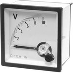
В русском мануале обратите на стр.72, на клеммы на схеме АМ АСМ — это выводы для подключения 10вольтового стрелочного прибора, который можно проградуировать в обороты… Точности индикации будет более чем достаточно для работы…
-
0
Лужу, паяю, станки ЧПУ починяю….
Еще частенько здесь болтаю: Телеграм сообщество ЧПУшников: t.me/cncunion
- Наверх
#19
![]()
OFFLINE
ithitym
Отправлено 02 Июнь 2015 — 19:09
Огромное спасибо за наданую информацию.Пожалуста уточните какой прибор можно брать.Пример где они стоять ,чтоб знать как они виглядят.
-
0
- Наверх
#20
![]()
OFFLINE
MiG
MiG
- Пол:Мужчина
- Из:Россия , Ковров
Отправлено 02 Июнь 2015 — 19:39
…например вот такой
стрелочный вольтметр с диапазоном измерения 0-10v
размер 72х72мм
или вот такой
Вольтметр стрелочный SF-40 шкала 0-10V
размер 40х40мм

Сообщение отредактировал MiG: 02 Июнь 2015 — 19:56
-
0
- Наверх
Серия HLP-A100 — это новое поколение универсальных векторных приводов Holip с высокой надежностью, высокой адаптивностью к окружающей среде, превосходным удобством для пользователя и отличными характеристиками управления.
Он может широко применяться во многих отраслях промышленности, таких как пластмасса, текстиль, станки, пищевая упаковка, химикаты, полиграфия, строительные материалы, камень, волочение проволоки, стекло, шаровые мельницы, экология, перегрузка вентиляторов и т.д.
Особенности продукта
Высокая надежность
- Длинный жизненный цикл
- Скорость вентилятора регулируется
- Строгая конструкция и тестирование производственной системы
Удобство для пользователя
- Простота в эксплуатации
- Настройка платы IO
- Небольшой размер
- Режим множественной установки
Высокая экологичность
- Независимая конструкция ветрового пути
- Покрытие PCBA 100%
- Радиатор с широким шагом зуба
- Легкая очистка и замена вентилятора
- Предусматривает опции IP5X
- Широкий диапазон напряжения
- Высокая адаптивность, характеристики EMC
- RFI переключатель
- ≥37 кВт в модели встроенного дросселя постоянного тока
- Интеллектуальная система управления отоплением
Технические характеристики
| Характеристика | Спецификация | |
| Источник питания | Напряжение питания | Однофазный / трехфазный 200 ~ 240 В -20% ~ + 10%; |
| Трехфазный 380 ~ 480В -20% ~ + 10%; | ||
| частота | 48-62Hz; | |
| Макс. несбалансированность | 3%; | |
| Мощность двигателя | Выходное напряжение | Три фазы 0-100% от напряжения питания |
| Выходная частота | V / F: 0-400 Гц, VVC +: 0-200 Гц; | |
| IO | вход | 6 цифровых входов (1 поддерживает импульсный вход, диапазон импульсов: 1 Гц ~ 100 кГц); |
| Питание | 2 аналоговых входа, оба могут принимать сигналы напряжения или тока. | |
| Контроль | ||
| Клеммы | Вывод | 2 цифровых выхода (1 поддерживает импульсный выход, диапазон импульсов: 1 Гц ~ 100 кГц); |
| 2 релейных выхода; | ||
| 2 аналоговых входа (1 можно выбрать в качестве выхода тока или напряжения через перемычку). | ||
| Источник питания | 1 + 10 В, максимальный выходной ток 10 мА; | |
| 1 24 В, максимальный выходной ток 200 мА; | ||
| связь | RS +, RS-, максимальная скорость передачи 115200 бит / с; | |
| Дисплей | 8 сегментов, 5 цифровых дисплеев | Частота отображения, предупреждения, статус и т. Д .; |
| Индикатор | Светлые FWD, REV, HZ, A, RPM отображают различные состояния привода; | |
| Считывание данных | Настройка частоты, выходной частоты, значения обратной связи, выходного тока, напряжения звена постоянного тока, выходного напряжения, выходной мощности, состояния входных клемм, состояния выходных клемм, аналогового входа, аналогового выхода, 1-10 записей о сбоях и накопленного рабочего времени и т. Д .; | |
| Окружающая среда | Ограждение | IP20; |
| Температура окружающей среды | 10 ℃ ~ 50 ℃, снижение использования при превышении 40 ℃; | |
| Влажность | 5% -85% (95% без конденсации); | |
| Вибрационный тест | ≤75 кВт: 1,14 г; | |
| ≥90 кВт: 0,7 г; | ||
| Максимум. высота над уровнем моря | 1000 м, снижение характеристик при использовании более 1000 м; | |
| Длина кабеля двигателя | Экран кабеля: 50 метров; Откидной кабель: 100 метров; | |
| Другие | Дроссель постоянного тока | ≥37 кВт встроенный |
| Тормозной блок | ≤22 кВт встроенный |
Функции продукта
| Основные функции управления | Режим управления | V / F, VVC +; |
| Пусковой момент | 0,5 Гц 150%; | |
| Перегрузочная способность | 150% 60 с, 200% 1 с; | |
| Частота переключения ШИМ | 2k ~ 16 кГц; | |
| Разрешение установки скорости | Цифровой: 0,001 Гц; | |
| Аналогия: 0,5 ‰ от макс. рабочая частота ; | ||
| Точность контроля скорости без обратной связи | 30 ~ 4000 об / мин: допуск ± 8 об / мин; | |
| Источник управляющей команды | LCP, цифровой терминал, локальная шина; | |
| Источник настройки частоты | LCP, аналоговая, импульсная, локальная шина; | |
| Управление рампой | Выбираемые 4-ступенчатые ступени: время увеличения и уменьшения 0,05–3600,00 с; | |
| Основные функции | Контроль скорости без обратной связи; Управление процессом с обратной связью; Управление моментом без обратной связи; Функция AMA; Намагничивание двигателя; Компенсация скольжения; Компенсация крутящего момента; Автоматическое регулирование напряжения; Управление V / F, Тормоз постоянного тока; Тормоз переменного тока; Ограничение скорости; Текущий предел; Быстрый старт; Функция сброса; Счетчик; Таймер; | |
| Функции приложения | Функция колебания; Многоскоростное управление через цифровой вход; SLC (включая контроль заказов и параллельное управление); Механическое торможение; ВВЕРХ ВНИЗ ; Относительное масштабирование | |
| Защита | Отсутствие защиты фазы двигателя; Низковольтная защита; Защита от перенапряжения; Защита от сверхтока; Защита от потери выходной фазы; Защита от короткого замыкания на выходе; Защита от замыкания на выходе; Тепловая защита двигателя; Функция тайм-аута в реальном времени; AMA Fails; Сбой процессора; Ошибки EEPROM; Кнопка замораживания; Повторяющиеся ошибки; LCP Invalid; LCP несовместимый; Параметр только для чтения; Ссылка вне диапазона; Неверно во время работы и т. д. | |
| Функции |
Характеристики по моделям
| Модель | Входное напряжение | Вход. ток | Вых. ток | Ном. мощность | Сила рассеивания | Расход воздуха | Нетто |
| (А) | (А) | (КВт) | (Вт) | (М3 / ч) |
(кг) | ||
| HLP-A1000D3721 | 1×200-240V | 7 | 2,5 | 0,37 | 17,7 | 51 | 1,3 |
| HLP-A1000D7521 | 1×200-240V | 13,9 | 5 | 0,75 | 33,3 | 51 | 1,3 |
| HLP-A10001D521 | 1×200-240V | 20,6 | 7,5 | 1,5 | 53,8 | 51 | 1,3 |
| HLP-A10002D221 | 1×200-240V | 30,4 | 11 | 2,2 | 75 | 51 | 1,3 |
| HLP-A10003D721 | 1×200-240V | 49,7 | 17 | 3,7 | 115,7 | 51 | 2 |
| HLP-A10005D521 | 1×200-240V | 62,4 | 25 | 5,5 | 160 | 124 | 5,6 |
| HLP-A10007D521 | 1×200-240V | 84 | 32 | 7,5 | 225 | 230 | 7,8 |
| HLP-A1000D3723 | 3×200-240V | 4 | 2,5 | 0,37 | 16,8 | 51 | 1,3 |
| HLP-A1000D7523 | 3×200-240V | 8,0 | 5 | 0,75 | 31,5 | 51 | 1,3 |
| HLP-A10001D523 | 3×200-240V | 12 | 7,5 | 1,5 | 51 | 51 | 1,3 |
| HLP-A10002D223 | 3×200-240V | 17,7 | 11 | 2,2 | 73,7 | 51 | 1,3 |
| HLP-A10003D723 | 3×200-240V | 27,2 | 17 | 3,7 | 110,9 | 51 | 2,0 |
| HLP-A10005D523 | 3×200-240V | 35,1 | 25 | 5,5 | 155 | 124 | 5,6 |
| HLP-A10007D523 | 3×200-240V | 43,4 | 32 | 7,5 | 210 | 124 | 5,6 |
| HLP-A100001123 | 3×200-240V | 61 | 45 | 11 | 323 | 272 | 7,8 |
| HLP-A100001523 | 3×200-240V | 73 | 61 | 15 | 447 | 300 | 18,5 |
| HLP-A1000D7543 | 3 × 380-440V |
3,7 | 2,3 | 0,75 | 38,5 | 51 | 1,3 |
| 3 × 440-480V | 3,2 | 2,1 | |||||
| HLP-A10001D543 | 3 × 380-440V |
6,4 | 4 | 1,5 | 49,0 | 51 | 1,3 |
| 3 × 440-480V | 5,5 | 3,6 | |||||
| HLP-A10002D243 | 3 × 380-440V |
8,9 | 5,6 | 2,2 | 65,2 | 51 | 1,3 |
| 3 × 440-480V | 7,7 | 5,1 | |||||
| HLP-A10004D043 | 3 × 380-440V |
+15,8 | 9,9 | 4,0 | 122,9 | 51 | 2,0 |
| 3 × 440-480V | 13,6 | 9 | |||||
| HLP-A10005D543 | 3 × 380-440V |
21,3 | 13,3 | 5,5 | 139,4 | 51 | 2,0 |
| 3 × 440-480V | 18,4 | 12,1 | |||||
| HLP-A10007D543 | 3 × 380-440V |
28,3 | 17,7 | 7,5 | 211,6 | 68 | 2.5 |
| 3 × 440-480V | 24,4 | 16,1 | |||||
| HLP-A100001143 | 3 × 380-440V |
35,9 | 25 | 11 | 262,4 | 124 | 5,8 |
| 3 × 440-480V | 31,4 | 22,7 | |||||
| HLP-A100001543 | 3 × 380-440V |
43,4 | 32 | 15 | 339,3 | 170 | 5,8 |
| 3 × 440-480V | 38,8 | 29,1 | |||||
| HLP-A10018D543 | 3 × 380-440V |
51,5 | 38 | 18,5 | 418,0 | 230 | 8 |
| 3 × 440-480V | 46,1 | 34,5 | |||||
| HLP-A100002243 | 3 × 380-440V |
61,0 | 45 | 22 | 468,2 | 272 | 8 |
| 3 × 440-480V | 54,5 | 40,9 | |||||
| HLP-A100003043 | 3 × 380-440V |
73 | 61 | 30 | 676,3 | 303 | 19 |
| 3 × 440-480V | 64 | 52 | |||||
| HLP-A100003743 | 3 × 380-440V |
72 | 75 | 37 | 795 | 374 | 22 |
| 3 × 440-480V | 65 | 68 | |||||
| HLP-A100004543 | 3 × 380-440V |
86 | 91 | 45 | 974,8 | 408 | 26 |
| 3 × 440-480V | 80 | 82 | |||||
| HLP-A100005543 | 3 × 380-440V |
110 | 112 | 55 | 1246 | 476 | 26 |
| 3 × 440-480V | 108 | 110 | |||||
| HLP-A100007543 | 3 × 380-440V |
148 | 150 | 75 | 1635 | 595 | 37 |
| 3 × 440-480V | 135 | 140 | |||||
| HLP-A100009043 | 3 × 380-440V |
175 | 180 | 90 | 2204 | 646 | 60 |
| 3 × 440-480V | 154 | 160 | |||||
| HLP-A100011043 | 3 × 380-440V |
206 | 215 | 110 | 2600 | 714 | 60 |
| 3 × 440-480V | 183 | 190 | |||||
| HLP-A100013243 | 3 × 380-440V |
251 | 260 | 132 | 3178 | 850 | 60 |
| 3 × 440-480V | 231 | 240 | |||||
| HLP-A100016043 | 3 × 380-440V |
304 | 315 | 160 | 3689 | 1029 | 99 |
| 3 × 440-480V | 291 | 302 | |||||
| HLP-A100018543 | 3 × 380-440V |
350 | 365 | 185 | 4268 | 1190 | 99 |
| 3 × 440-480V | 320 | 335 | |||||
| HLP-A100020043 | 3 × 380-440V |
381 | 395 | 200 | 4627 | 1292 | 99 |
| 3 × 440-480V | 348 | 361 | |||||
| HLP-A100022043 | 3 × 380-440V |
420 | 435 | 220 | 4935 | 1411 | 99 |
| 3 × 440-480V | 383 | 398 | |||||
| HLP-A100025043 | 3 × 380-440V |
472 | 480 | 250 | 5323 | 1564 | 250 |
| 3 × 440-480V | 436 | 443 | |||||
| HLP-A100028043 | 3 × 380-440V |
525 | 540 | 280 | 6543 | 1700 | 250 |
| 3 × 440-480V | 475 | 490 | |||||
| HLP-A100031543 | 3 × 380-440V |
590 | 605 | 315 | 7251 | 1870 | 250 |
| 3 × 440-480V | 531 | 540 | |||||
| HLP-A100035543 | 3 × 380-440V |
647 | 660 | 355 | 7497 | 2125 | 250 |
| 3 × 440-480V | 580 | 590 | |||||
| HLP-A100041543 | 3 × 380-440V |
718 | 745 | 415 | 8284 | 2380 | 250 |
| 3 × 440-480V | 653 | 678 |
Размеры установки

| Корпус | Напряжение и питание | Размеры(mm) | ||||||||
| 1×200-240V | 3×200-240V | 3×380-480V | W | H | D | W1 | H1 | W2 | d | |
| A0 | 0.37-1.5kW | 0.37-1.5kW | 0.75-2.2kW | 125 | 210 | 152 | 104 | 194 | — | 4.5 |
| A1 | 2.2-3.7kW | 2.2-3.7kW | 4.0-5.5kW | 145 | 250 | 167 | 124 | 230 | — | 4.5 |
| A2 | — | — | 7.5kW | 155 | 263 | 177 | 133 | 243 | — | 4.5 |
| A3 | 5.5kW | 5.5-7.5kW | 11-15kW | 192 | 365 | 189 | 150 | 340 | — | 6.5 |
| A4 | 7.5kW | 11kW | 18.5-22kW | 216 | 420 | 194 | 150 | 395 | — | 6.5 |
| A5-1 | — | 15kW | 30-37kW | 292 | 517 | 229 | 240 | 492 | — | 9 |
| A5-2 | — | — | 45-55kW | 292 | 562 | 249 | 240 | 537 | — | 9 |
| A6 | — | — | 75kW | 292 | 665 | 277 | 240 | 640 | — | 9 |
| A7 | — | — | 90-132kW | 350 | 799 | 375 | 220 | 765 | 280 | 10.5 |
| A8 | — | — | 160-220kW | 486 | 900 | 390 | 345 | 863 | 410 | 10.5 |
| A9 | — | — | 250-415kW | 600 | 1568 | 509 | 424 | 304 | — | 15 |
HLP-C100 Series
7.1 Parameter group 00: operation/display
Chapter 8 Accessory Specifi cation
8.1 Braking resistor
8.2 LCP Mounting Kit
8.2.1 External LCP Communication Cable
8.2.2 Mounting steps
9.1 EMC-Correct Installation
9.2 RFI Switch
10.1 Fault list
11.1 Note
11.2 Storage and transport
12.1 Format specifi cation
12.2 Coil addressing
12.4 Force single coil
12.8 Read/write array
HLP-C100 Series Operating Manual
— 33 —
— 33 —
— 35 —
— 39 —
— 41 —
— 51 —
— 54 —
— 55 —
— 59 —
— 60 —
— 62 —
— 65 —
— 67 —
— 72 —
— 72 —
— 72 —
— 72 —
— 73 —
— 73 —
— 73 —
— 74 —
— 74 —
— 76 —
— 78 —
— 78 —
— 78 —
— 79 —
— 79 —
— 79 —
— 81 —
— 82 —
— 82 —
— 83 —
— 84 —
— 85-
— 85 —
— 87 —
Технические характеристики
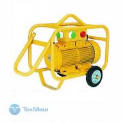
- Номинальная мощность, кВт
- 220
- Входное напряжение
- 3×380-440V50/60Hz
- Вес, кг
- 99
- Габариты, ДхШхВ, мм
- 486х345х863
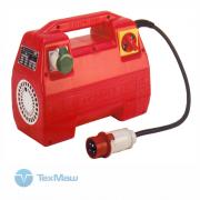
Отзывы: Частотный преобразователь Holip HLP-SK190022043
Похожие товары
Код товара:
2746
- Масса, кг:
- 15
- Количество выходов:
- 1
- Напряжение вход/выход, В:
- 380/42
- Мощность, кВт:
- 1.8
- Выход. ток:
- 13
79 521
RUB/шт.
с НДС
- Масса, кг:
- 15
- Количество выходов:
- 1
- Напряжение вход/выход, В:
- 380/42
- Мощность, кВт:
- 1.8
- Выход. ток:
- 13
Код товара:
2747
- Масса, кг:
- 17
- Количество выходов:
- 1
- Напряжение вход/выход, В:
- 2200/42
- Мощность, кВт:
- 1.3
- Выход. ток:
- 13
88 456
RUB/шт.
с НДС
- Масса, кг:
- 17
- Количество выходов:
- 1
- Напряжение вход/выход, В:
- 2200/42
- Мощность, кВт:
- 1.3
- Выход. ток:
- 13
Код товара:
2748
- Масса, кг:
- 25
- Количество выходов:
- 2
- Напряжение вход/выход, В:
- 380/42
- Мощность, кВт:
- 2.7
- Выход. ток:
- 23
105 432
RUB/шт.
с НДС
- Масса, кг:
- 25
- Количество выходов:
- 2
- Напряжение вход/выход, В:
- 380/42
- Мощность, кВт:
- 2.7
- Выход. ток:
- 23
Код товара:
2749
- Масса, кг:
- 27
- Количество выходов:
- 2
- Напряжение вход/выход, В:
- 220/42
- Мощность, кВт:
- 2
- Выход. ток:
- 24
109 542
RUB/шт.
с НДС
- Масса, кг:
- 27
- Количество выходов:
- 2
- Напряжение вход/выход, В:
- 220/42
- Мощность, кВт:
- 2
- Выход. ток:
- 24
Код товара:
2750
- Масса, кг:
- 30
- Количество выходов:
- 2
- Напряжение вход/выход, В:
- 380/42
- Мощность, кВт:
- 2.8
- Выход. ток:
- 24
117 048
RUB/шт.
с НДС
- Масса, кг:
- 30
- Количество выходов:
- 2
- Напряжение вход/выход, В:
- 380/42
- Мощность, кВт:
- 2.8
- Выход. ток:
- 24
Код товара:
2751
- Масса, кг:
- 33
- Количество выходов:
- 2
- Напряжение вход/выход, В:
- 220/42
- Мощность, кВт:
- 2
- Выход. ток:
- 24
120 622
RUB/шт.
с НДС
- Масса, кг:
- 33
- Количество выходов:
- 2
- Напряжение вход/выход, В:
- 220/42
- Мощность, кВт:
- 2
- Выход. ток:
- 24
Код товара:
2752
- Масса, кг:
- 34
- Количество выходов:
- 3
- Напряжение вход/выход, В:
- 380/42
- Мощность, кВт:
- 4
- Выход. ток:
- 36
175 125
RUB/шт.
с НДС
- Масса, кг:
- 34
- Количество выходов:
- 3
- Напряжение вход/выход, В:
- 380/42
- Мощность, кВт:
- 4
- Выход. ток:
- 36
Код товара:
2753
- Масса, кг:
- 70
- Количество выходов:
- 3
- Напряжение вход/выход, В:
- 380/42
- Мощность, кВт:
- 6
- Выход. ток:
- 50
205 504
RUB/шт.
с НДС
- Масса, кг:
- 70
- Количество выходов:
- 3
- Напряжение вход/выход, В:
- 380/42
- Мощность, кВт:
- 6
- Выход. ток:
- 50
Код товара:
2754
- Масса, кг:
- 80
- Количество выходов:
- 4
- Напряжение вход/выход, В:
- 380/42
- Мощность, кВт:
- 9
- Выход. ток:
- 61
261 347
RUB/шт.
с НДС
- Масса, кг:
- 80
- Количество выходов:
- 4
- Напряжение вход/выход, В:
- 380/42
- Мощность, кВт:
- 9
- Выход. ток:
- 61
Код товара:
2755
- Масса, кг:
- 90
- Количество выходов:
- 4
- Напряжение вход/выход, В:
- 380/42
- Мощность, кВт:
- 11
- Выход. ток:
- 82
330 593
RUB/шт.
с НДС
- Масса, кг:
- 90
- Количество выходов:
- 4
- Напряжение вход/выход, В:
- 380/42
- Мощность, кВт:
- 11
- Выход. ток:
- 82
Код товара:
2761
- Масса, кг:
- 18
- Количество выходов:
- 1
- Напряжение вход/выход, В:
- 220/42
- Мощность, кВт:
- 1
- Выход. ток:
- 15
75 590
RUB/шт.
с НДС
- Масса, кг:
- 18
- Количество выходов:
- 1
- Напряжение вход/выход, В:
- 220/42
- Мощность, кВт:
- 1
- Выход. ток:
- 15
Код товара:
2762
- Масса, кг:
- 18
- Количество выходов:
- 1
- Напряжение вход/выход, В:
- 380/42
- Мощность, кВт:
- 1
- Выход. ток:
- 15
84 078
RUB/шт.
с НДС
- Масса, кг:
- 18
- Количество выходов:
- 1
- Напряжение вход/выход, В:
- 380/42
- Мощность, кВт:
- 1
- Выход. ток:
- 15

Частотный преобразователь Holip HLP-SK190022043

Ваша корзина пуста
Выберите в каталоге интересующий товар
и нажмите кнопку «В корзину».
Перейти в каталог

Отложенных товаров нет
Выберите в каталоге интересующий товар
и нажмите кнопку ![]()
Перейти в каталог

Частотный преобразователь Holip HLP-SK190018543
Частотный преобразователь Holip HLP-SK190018543
661 494 руб.
661 494 руб.
|
185 |
|
|
380 ~ 480 |
|
|
99 |
|
|
486х345х863 |
Калькулятор доставки

Выбрать город
![]()
Самовывоз (ТК)
Доставка (ТК)

- Характеристики
- Отзывы
Частотный преобразователь Holip HLP-SK190018543: характеристики
Габариты, ДхШхВ, мм
486х345х863
Введите наименование населенного пункта
Пожалуйста, подождите

Преобразователь частоты — это силовой электронный блок, который является посредником между системой управления и электродвигателем. Он обеспечивает питание для двигателя, защищает его и задаёт необходимый режим работы — разгон, торможение или постоянное изменение скорости.
Для примера возьмем шлифовальный станок, который часто можно встретить в промышленном цеху или в столярной мастерской. Для качественной работы станка движение должно осуществляться в двух направлениях, скорость вращения ленты — меняться плавно, а аварийная кнопка мгновенно отключать питание. Без преобразователя частоты тут точно не обойтись.

Рис.1 Внешний вид шлифовального станка.
Подключение силовых цепей
Все провода, подключаемые к частотному преобразователю, можно разделить на 2 группы: силовые и контрольные. Рассмотрим подключение силовых.
Три провода сетевого питания 380 В, 50 Гц — клеммы R, S, T + провод заземления PE. Нейтраль частотному преобразователю не нужна. Даже если она у вас есть, подключать не нужно. А вот провода питания можно подключать в любом порядке. При необходимости чередование фаз можно изменить в программе частотника.
Три провода питания двигателя — клеммы U, V, W + провод заземления PE. На выходе напряжение может меняться от 0 до 380 В, а частота от 0 до 500 Гц. В этом и кроется смысл работы частотного преобразователя — он позволяет изменять скорость двигателя от нуля до номинального значения и даже выше, если это позволяет механика.

Рис.2 Подключение силовых цепей
Подключение цепей управления
С контрольными проводами всё несколько сложнее. Тут нужно хорошо подумать, прежде чем подключать. На выбор целая россыпь дискретных и аналоговых входов и выходов. В документации производители чаще всего публикуют стандартную схему подключения с заводскими настройками, но для каждого механизма на деле нужна своя схема и индивидуальные настройки.

Рис.3 Подключение цепей управления
У нас задача не самая сложная. Для управления шлифовальной машиной достаточно кнопок «Пуск», «Стоп», переключателя «Вперед – Назад» и переменного резистора для изменения скорости вращения, его ещё называют потенциометром.
К дискретным входам DI подключаются сигналы, которые могут принимать одно из двух состояний — «вкл» и «выкл» или логический 0 и 1. В нашей схеме это кнопки «Пуск», «Стоп», переключатель направления и аварийный «грибок». Мы будем использовать кнопки без фиксации, которые уже установлены на станке.
К аналоговым входам AI подключаются сигналы с непрерывно меняющейся величиной тока 4…20 мА или напряжения 0…10 В. Это могут быть датчики, сигналы от контроллера или другого внешнего устройства. В нашем случае — это ручка потенциометра, которая обеспечивает плавную регулировку скорости.
Потенциометр или переменный резистор — это регулируемый делитель напряжения с тремя контактами.

Рис.4 Внешний вид потенциометра
На два крайних неподвижных контакта подаётся постоянное напряжение 10 В от частотного преобразователя, а средний подвижный контакт служит для снятия текущей величины напряжения, которая зависит от положения ручки. Если ручка повернута наполовину, значит и напряжение будет только половинное = 5 В. Преобразователь пересчитает напряжение в задание скорости и разгонит двигатель.

Рис.5 Подключение потенциометра
Любой потенциометр не подойдёт, необходим с сопротивлением от 2 до 5 кОм, чтобы аналоговый вход стабильно работал. А ещё он должен быть с удобной ручкой, ведь крутить его придётся постоянно. Мощность может быть любой, даже 0,125 Вт достаточно. Идеально подойдёт XB5AD912R4K7 с сопротивлением 4,7 кОм.
На дискретные — DO и аналоговые выходы AO преобразователь выдает информацию о своем текущем состоянии, скорости или токе двигателя, достижении заданных значений или выходе за их пределы. В нашем случае выходы не используются, поэтому подключать нечего.
Настройка
Недостаточно просто подключить все провода к частотнику, его ещё нужно правильно настроить, чтобы механизм работал стабильно и долго. Для этого в частотном преобразователе несколько сотен параметров. Конечно, все настраивать не придётся, но вот основные — обязательно.
Настройка осуществляется с помощью клавиш на встроенной панели управления. С ними всё предельно просто.
Кнопка PRG отвечает за вход и выход из режима программирования. Кнопки вверх, вниз и вбок осуществляют навигацию внутри меню, а кнопка Enter — подтверждает выбор параметра или его значения.
MF.K — это дополнительная функциональная кнопка, которую можно настроить на необходимое действие, например переключение между местным и дистанционным управлением или смену направления вращения.
Зеленая и красная кнопки — это Пуск и Стоп, если управление осуществляется с панели.
Если запутались, не беда. Нужно несколько раз нажать на кнопку PRG, чтобы вернуться к исходному состоянию.

Рис.6 Внешний вид панели управления
А теперь к параметрированию
Во-первых, необходимо дать понять частотному преобразователю, какой двигатель к нему подключен. Для этого в параметры с F1-01 по F1-05 запишем значения с шильдика двигателя:
F1-01 = 1,5 кВт — номинальная мощность двигателя
F1-02 = 380 В — номинальное напряжение двигателя
F1-03 = 3,75 А — номинальный ток двигателя
F1-04 = 50 Гц — номинальная частота двигателя
F1-05 = 1400 об/мин — номинальная скорость двигателя

Рис.7 Шильдик двигателя
Теперь, когда основные данные о двигателе есть, нужно провести автонастройку. Этот процесс нужен, чтобы частотный преобразователь ещё лучше адаптировался к работе с конкретным двигателем: вычислил сопротивление и индуктивность обмоток. Так управление будет точнее, а экономия энергии — больше.
Для запуска процедуры устанавливаем F1-37 = 1 — статическая автонастройка и нажимаем кнопку «Run» на панели управления. Через пару минут дисплей переходит в исходное состояние и частотник готов к работе.
Далее переведём управление на внешние кнопки и настроим его
В нашем случае подойдёт трёхпроводное управление, где кнопка «Стоп» осуществляет разрешение на работу, кнопка «Старт» — запуск станка, а переключатель выбирает направление вращения.

Рис.8 Схема трёхпроводного управления
Настроим эти параметры:
F0-02 = 1 — управление через клеммы управления
F0-03 = 2 — задание частоты с AI1 (потенциометр)
F4-00 = 1 — пуск
F4-01 = 2 — выбор направления движения
F4-02 = 3 — разрешение работы
F4-03 = 47 — аварийный останов
F4-11 = 3 — режим трёхпроводного управления
Теперь станок начинает оживать, реагирует на нажатие кнопок и вращение ручки скорости. Остаётся настроить время разгона, торможения и проверить на практике удобство использования. Наш частотный преобразователь настроен и готов к использованию!
Защита и безопасность
Преобразователь частоты — умное устройство. После настройки в работу включаются все защитные функции, которые в случае аварии сберегут и сам частотник, и двигатель, и механизм.
Например, при заклинивании: преобразователь вычислит, что ток двигателя намного выше номинального, который мы установили в параметре F1-03 ранее, выдаст ошибку «Перегрузка двигателя» и отключится. Двигатель не перегреется и не сгорит, а механика останется целой.
А если возникла угроза здоровью оператора или поломки оборудования — спасет аварийная кнопка «грибок». При её нажатии преобразователь в мгновение остановит станок и отключит питание. Никто не пострадает!
Вместо заключения
Настройка частотного преобразователя — процесс увлекательный. Порой преобразователь берёт на себя не только управление двигателем, но и целой системой и может заменить даже простой контроллер. К частотнику можно подключать датчики, лампы индикации, реле и даже контакторы. Применение преобразователю можно найти везде: от насосов и конвейеров до сложных станков, подъёмников и лифтов. Главное внимательно изучать документацию и делать всё по порядку, тогда всё обязательно получится.
Ещё по теме
Настройка частотного преобразователя для регулирования давления в трубопроводе
Как настроить управление частотным преобразователем по сети Modbus
Инструкция по эксплуатации и чертежи MD310
Каталог с актуальными ценами
Specifications:
|
Accompanying Data:
Holip HLP-C100 Series Inverter PDF Operating Manual (Updated: Sunday 12th of February 2023 07:33:02 PM)
Rating: 4.5 (rated by 45 users)
Compatible devices: G3800 X036, HLP-A100 Series, HLP-P Series, HLP-A Series, hlp-c+, M-Series, HG2201-A, HLP-NV Series.
Recommended Documentation:
Holip HLP-C100 Series: Text of Operating Manual
(Ocr-Read Version Summary of Contents, UPD: 12 February 2023)
Holip HLP-C100 Series: Recommended Instructions
S64-R2, SB65ELE, 46UL610U, JB400DP


-
Inversor de Energía de 3000 VatiosModelo: PKC0AWManual del Propietario e Información de GarantíaLea completamente estas instrucciones antes de usar este producto.Conserve este Manual del Propietario para referencia futura.P/N XXXXX, 1/0913000 Watt Power InverterModel No.: PKC0AWOwner’s Manual and Warranty InformationRead these instructions completely before using this product.Retain …
PKC0AW 10
-
MB079tdp-z02_mb (10A2)TDP 0,2 • TDPZ 0,2Analog-Tacho/Doppel-Tacho Ausführungen mit EURO-FlanschTachogenerator/Twin TachogeneratorVersions with EURO angeMontage- und BetriebsanleitungInstallation and operating instructions …
HUBNER TDP 0,2 Series 32
-
SI23 Solar Pump Inverter Manual 1Chapter 1 Safety Requirement and Cautions To ensure safety of your health, equipment and property, please read this chapter carefully before using the frequency inverter and act in compliance with the instructions when installing,ebugging, running and overhauling the frequency inverter. 1.1 Safety Definition Danger: it will c …
SI23-D1 series 31
-
OPERATING AND SERVICE MANUAL 5065A RUBIDIUM VAPOR FREQUENCY STANDARD WaHWBMfC- >»^»io % * # (a) ~* Reproduced with Permission. courtesy of Agilent Technologies, Inc. PDF produced IS September 2009 by Brian Kirby — KD4FM NOT FOR RESALE a HEWLETT PACKARD 5 …
5065A 355
-
INVERTER MIG / MAGONDULEUR MIG / MAGMIG-135A • MIG-150RThis manual provides important safety information and instructions on how to set up your welder. Every welding situation has the potential for personal injury. In order to minimize that risk, it’s important to read this manual carefully.Keep this manual in a safe place, review it frequently and ensure that …
MIG-135A 18
-
INSTRUCTION MANUAL1234INVERTERPlug-in optionFR-A7AX16 bit digital input functionPRE-OPERATION INSTRUCTIONSINSTALLATION AND WIRINGCONNECTION DIAGRAM AND TERMINALPARAMETERSA7AX.book 1 ページ 2005年9月22日 木曜日 午後7時40分 …
FR-A7AX 33
-
1 E3-MAC Series by Isolite Installation/Operation Manual for E3-MAC Emergency Lighting Central Inverter System 1.0KW – 3.0KW Models 1KW Model – Single Cabinet IMPORTANT SAFEGAURDS When using electrical equipment, basic safety precautions should always be followed including the following: READ AND FOLLOW ALL SAFETY INSTRUCTIONS A. Do not use outdoors B. Do not m …
E3-MAC Series 34
-
Fronius prints on elemental chlorine free paper (ECF) sourced from certified sustainable forests (FSC)./ Perfect Charging / Perfect Welding / Solar Energy42,0410,2024 019-17092019Fronius Symo — Installation10.0-3-M / 12.5-3-M / 15.0-3-M17.5-3-M / 20.0-3-MInstallation InstructionGrid connected inverter FIND YOUR OPERATING MANUALS FIND YOUR OPERATING MANUALSwww …
Symo Series 64
-
Instruction for installation, start-up, use and maintenance for Masoneilan* 12000 Series levels installed in potentially explosive atmospheres. GEA32346A (former 186034) 03/2016 — English *Denotes a trademark of General Electric Company. The equipment that you have just bought was designed, manufactured and tested in accordance with the essential safety requ …
12000 26
-
INSTRUCTIONS This product is charged by solar power. It can last over 1 hour of continuous use after charging for one full day in sunny conditions, or longer, up to 2-4 hours, in ideal conditions.NOTE:1. This product should be charged on a sunny day in a location where the solar panel can receive optimal sun coverage.2. On cloudy and rainy days, the lamp can be charg …
NA4177 2
Additional Information:
Popular Right Now:
Operating Impressions, Questions and Answers:
Описание
Частотные преобразователи Holip серии SK190– это устройства, предназначенные для корректировки и нормализации скорости оборотов электродвигателей асинхронного вида. Работают, изменяя в нужную сторону частоту напряжения сети электропитания.
Технические характеристики:
Страна бренд

Страна изготовитель
Эксперт-рейтинг:

В формировании рейтинга участвуют только профессионалы: сервисные сотрудники, старшие менеджеры и логисты компании. Эксперт рейтинг — это способ реализовать наши знания в трёх базовых критериях:
- Качество сборки — прочность, выцветание пластика со временем, крепление элементов.
- Долговечность — качество установленных компонент, страна изготовления узлов, класс защиты, сплав головки и ресивера, статистика рекламаций.
- Производительность — количество воздуха производимое компрессором в сравнении с точными аналогами по мощности, давлению, питанию и конструкции.
рейтинг покупателей:
Отзывы (0) | вопросы (0)
Написать отзыв
Будем рады узнать ваше мнение!
Выберите то количество звёзд, которое отражает ваше общее удовлетворение товаром.