Blue Box
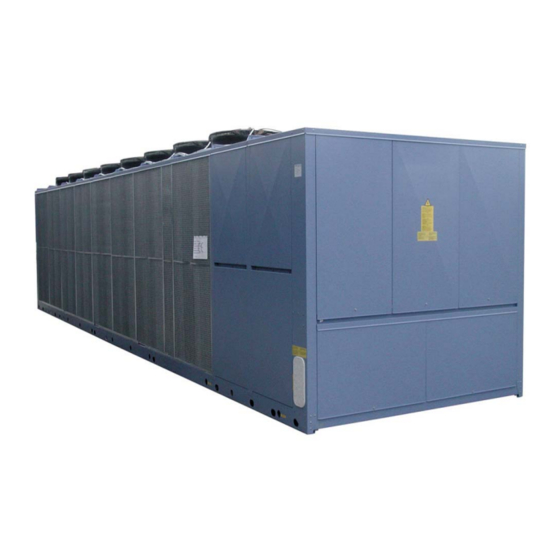
Чиллеры Blue Box серии ZETA 2002 (38 — 266 кВт) с воздушным охлаждением конденсатора, осевыми вентиляторами и
герметичными спиральными компрессорами. Инструкции по монтажу, эксплуатации и техническому обслуживанию.
Скачать
Pdf 2.54 Mb
Язык: RU
-
Contents
-
Table of Contents
-
Troubleshooting
-
Bookmarks
Quick Links
KAPPA V SR
635 ÷ 1065 kW
Installation, operating,
and maintenance
manual
Water chillers
Manual
Issue
Replaces
Air/water
self-contained
ISO 9001 — Cert. n. 0201
101070B02
02.03
06.02
0062
Axial fans and
screw compressors
Related Manuals for Blue Box KAPPA V SR
Summary of Contents for Blue Box KAPPA V SR
-
Page 1
KAPPA V SR 101070B02 Manual 02.03 Issue 635 ÷ 1065 kW 06.02 Replaces Installation, operating, and maintenance manual 0062 Water chillers Air/water Axial fans and self-contained screw compressors ISO 9001 — Cert. n. 0201… -
Page 3: Table Of Contents
4.2.2 Spring Anti-Vibration Isolators WATER PIPING CONNECTIONS RECOMMENDED HYDRAULIC CIRCUIT DIAGRAM FOR KAPPA V SR HYDRAULIC CIRCUIT DIAGRAM VERSION KAPPA V SR /ST 2PS EVAPORATOR WATER PIPE CONNECTIONS FLEXIBLE JOINTS DESUPERHEATER HYDRAULIC CONNECTION (optional) HEAT RECOVERY EXCHANGER HYDRAULIC CONNECTIONS (OPTIONAL)
-
Page 4
4.14 OPERATION WITH LOW TEMPERATURE CHILLED WATER AT EVAPORATOR TABLE 1 — FREEZING POINT FOR WATER-ANTIFREEZE MIXTURES OPERATING LIMITS EVAPORATOR PRESSURE DROP PUMPS AVAILABLE PRESSURE — MODEL KAPPA V SR /ST 2PS ELECTRICAL PANEL LAY OUT 4.15 ELECTRICAL CONNECTIONS 4.15.1 General 4.15.2… -
Page 5
INTRODUCTION REPAIRING THE REFRIGERANT CIRCUIT 8.3.1 Leak test 8.3.2 High vacuum and dehydration of the refrigerant circuit 8.3.3 Refrigerant charge ENVIRONMENTAL CONSIDERATIONS TROUBLESHOOTING DECOMMISSIONING THE UNIT REFRIGERANT CIRCUIT OVERALL DIMENSIONS, WEIGHTS AND HYDRAULIC CONNECTIONS… -
Page 7: Kappa V Sr Water Chiller
KAPPA V SR water chiller UNIT FRAME Self supporting frame with removable panels, internally coated with expanded polyurethane sound-absorbing material; constructed from galvanized sheet steel with RAL 5014 powder paint baked at 180°C to provide a durable weatherproof finish. Threaded fasteners in stainless steel.
-
Page 8: Testing
KAPPA V SR /DC: unit with heat recovery condenser. In addition to the components of version KAPPA V SR this unit includes for each compressor a 100% heat recovery condenser for the production of hot water. The microprocessor automatically controls the water tempe- rature and the heat recovery safety switch.
-
Page 9: Hydraulic Circuit Accessories
— Set-point variable with remote signal (0-1 V, 0-10 V, 0-4 mA, 0-20 ma) VARIOUS ACCESSORIES — Rubber or spring type anti-vibration mounts — Anti-corrosion treatment of coils for use in aggressive environments — Timber crate packing — Pallet/skid for container shipment — Non-standard RAL paint colours Blue Box 3…
-
Page 10: Series
SERIES The KAPPA V SR series of water cooled chillers and heat pumps, are available in various sizes with capacities from 635 to 1.065 kW (capacities refer to water entering/leaving 12/7 °C, ambient air 35 °C) in the following basic versions:…
-
Page 11: Technical Data
TECHNICAL DATA Refrigerant R407C MODEL KAPPA V SR 65.2 73.2 80.2 84. 2 C o o l i n g ( * ) Nominal capacity 635,6 710,2 769,3 813,7 Evaporator water flow 30,37 33,93 36,76 38,88 109.316 122.150 132.323 139.963…
-
Page 12
2.432 Shipping weight 7.681 7.632 7.816 8.576 (1) total water flow (*) ambient air temperature 35 °C; evaporator entering/leaving water temperature 12-7 °C;. (**) ambient air temperature 8 °C DB, 50%RH; condenser entering/leaving water temperature 40-45 °C. Blue Box 6… -
Page 13: Electrical Characteristics And Components
(2) maximum current before safety cut-outs stop the unit. This value is never exceeded and must be used to size the electrical supply cables and relevant safety devices (refer to electrical wiring diagram supplied with the unit). All values in brackets are refer to /ST version (units with storage tank) or units with pump. Blue Box 7…
-
Page 14: Technical Data — Kappa V Sr /St 2Ps
TECHNICAL DATA — KAPPA V SR /ST 2PS Refrigerant R407C M O D E L K A P P A V S R 65.2 73.2 80.2 84. 2 Pump section Evaporator water flow 30,37 33,93 36,76 38,88 109.316 122.150 132.323 139.963…
-
Page 15: Sound Pressure Levels
106.3 73,1 77,3 76,0 74,9 76,1 73,9 65,0 54,3 80,0 Lcc: sound pressure values measured in free field conditions with phonometer at 1 m from the unit and 1,5 m from ground levelon the condensing coil side. Blue Box 9…
-
Page 16: Field Of Application
Delivery Note which must be signed by both parties. Blue Box or their Agent must be informed, as soon as possible, of the extent of the damage.
-
Page 17
(1) Side panel protection (not supplied) (2) Lifting holes Figure 1 Caution: ensure that the method of lifting does not allow the unit to slip from chains and slings or turn-over or slide from lifting devices. Blue Box 11… -
Page 18: Safety Precautions
— The compressor compartment contains various high temperature components. Adopt maximum caution when working in the vicinity of the compressors and avoid touching any parts of the unit without appropriate protection. — Do not work within the theoretical discharge trajectory of the relief valves. Blue Box 12…
-
Page 19: Mechanical Hazards
UNI EN 294. All the protections supplied to limit and enclose the fan compartments cannot be removed without the use of special tools. Blue Box 13…
-
Page 20: Thermal Hazards
Normal operating regime Contact with electrically live units designed built parts (direct contact). compliance with harmonised standard EN Elements carrying electrical 60204-1. Maintenance current in the case of faults. Inappropriate insulation. Radiated heat due to short- circuits or overloads. Blue Box 14…
-
Page 21: Refrigerant Safety Data — R407C
Personal precautions: Use personal protective equipment. Evacuate personnel to safe RELEASE MEASURES: areas. Do not breath vapours or spray mist. Ensure adequate ventilation. Methods for cleaning Shut off leaks it without risk. Solid evaporates. Ensure adequate ventilation. Blue Box 15…
-
Page 22
S59 — Refer to manufacturer/supplier for information on recovery/recycling. Contaminated Do not reuse empty containers. Empty pressure vessels should be packaging: returned to supplier. 12. TRANSPORT No. O.N.U. 3340 INFORMATIQN: ADR/RID UN 3340 Refrigerant gas R407C, 2, 2° A, ADR/RID Label: 2 Blue Box 16… -
Page 23: Positioning
— possible sound reverberation. All models in the KAPPA V SR series are designed for exterior installation: to avoid the risk of air recirculation units must not be covered by a shelter roof or located under trees (even if the unit is only partially covered).
-
Page 24
The units should not be installed next to offices, bedrooms, or other areas where low noise levels are a necessity. To avoid excess sound reverberation do not install the units in narrow or confined spaces. Figure 3 Blue Box 18… -
Page 25: Installation
High walls near the machine may interfere with correct functioning. When units are side by side the minimum distance between them should be 3 metres (see figure 4). SIDE BY SIDE UNITS 3 m min. 0.75 m (*) 1.5 m Figure 4 Blue Box 19…
-
Page 26: Anti-Vibration Isolators (Option)
The load of the unit is and two bolts and washers. supported by the full surface of the isolators. The load is not exerted on the bolt. Figure 6 Blue Box 20…
-
Page 27: Water Piping Connections
— Vent valves, to be installed in the upper parts of the circuit, for air bleeding. — Expansion device with accessories for circuit pressurisation, water thermal expansion compensation and system filling. — Unload valve and if necessary drainage tank for circuit emptying during maintenance and seasonal stop. Blue Box 21…
-
Page 28: Recommended Hydraulic Circuit Diagram For Kappa V Sr
Blue Box 22…
-
Page 29: Hydraulic Circuit Diagram Version Kappa V Sr /St 2Ps
HYDRAULIC CIRCUIT DIAGRAM VERSION KAPPA V SR /ST 2PS Blue Box 23…
-
Page 30: Evaporator Water Pipe Connections
It is mandatory to install a flow switch (supplied with the unit) on the evaporator water outlet connection identified by the following decal: EVAPORATOR WATER It is compulsory to install a metallic filter, on the water inlet piping. If a filter is not installed the warranty will be terminated immediately. Blue Box 24…
-
Page 31: Flexible Joints
4) Line up the connection and the counter-connection, place the gasket in the original position and if possible lubricate it on contact areas with a non-aggressive oil or grease. 5) Assemble the joint and tighten the nuts. Joint Gasket Figure 7 Blue Box 25…
-
Page 32: Desuperheater Hydraulic Connection (Optional)
RECOVERY WATER Heat recovery water outlet: RECOVERY WATER On HP version units the hydraulic connection to the desuperheater must be isolated during heat pump operation Entering/leaving chilled water Desuperheater recovery water outlet Desuperheater recovery water inlet Figure 8 Blue Box 26…
-
Page 33: Heat Recovery Exchanger Hydraulic Connections (Optional)
30 °C. DIAGRAM WITH 3-WAY VALVE 3-way valve Recovery water outlet Recovery water inlet Figure 9 Blue Box 27…
-
Page 34: Pressure Relief Valves
The vent pipe must be sized no smaller than the relief valve and it must not be supported from the valve. Caution: The relief valve must be directed into a safe zone where no injuries can be caused to people. Blue Box 28…
-
Page 35: Water Flow Rate To Evaporator
This control is calibrated and factory tested. Warning: speed control calibration settings must not be altered. If it proves necessary to alter speed calibration settings, this task must be entrusted to a skilled engineer, who should refer to the attached instruction sheet. Blue Box 29…
-
Page 36: Operation With Low Temperature Chilled Water At Evaporator
In the case of ST versions with a glycol content greater than 30% pumps with special seals must be specified at the time of the order. Blue Box 30…
-
Page 37: Operating Limits
OPERATING LIMITS KAPPA V SR — Refrigerant R407C Refrigeratore / Chiller Con dispositivi opzionali per basse Raffreddamento temperature dell’aria esterna. Cooling With low ambient temperature kit. Ambient air temperature [°C] Pompa di calore Heat pump Riscaldamento Heating Con dispositivi opzionali per basse Raffreddamento temperature dell’aria esterna.
-
Page 38: Evaporator Pressure Drop
EVAPORATOR PRESSURE DROP 73.2 80.2 100.2 106.3 65.2 84.2-88.2-93.2 Portata acqua [l/s] Water Flow [ l / s ] The water temperature rise for all versions must be between 3 °C (min) and 8 °C (max) Blue Box 32…
-
Page 39: Pumps Available Pressure — Model Kappa V Sr /St 2Ps
PUMPS AVAILABLE PRESSURE — MODEL KAPPA V SR /ST 2PS PREVALENZA UTILE 93.2 84.2-88.2 65.2-73.2 100.2 80.2 106.3 Portata acqua [l/s] Water flow [l/s] Water flow Blue Box 33…
-
Page 40: Electrical Panel Lay Out
ELECTRICAL PANEL LAY OUT MODELS 65.2 — 100.2 Blue Box 34…
-
Page 41
ELECTRICAL PANEL LAY OUT MODEL 106.3 Remote electric panel Option — ST version See sheet 2 Blue Box 35… -
Page 42
FUSES CAPAC. POW. FACT. CORRECT. COMPR. 1 RELAIS START 3 FU42 FUSES CAPAC. POW. FACT. CORRECT. COMPR. 2 MAIN SWITCH FU46 FUSES CAPAC. POW. FACT. CORRECT. PUMPS TEMPERATURE SENSOR FU50 FUSES AUX. TRANSFORMER AUX. TRANSFORMER FU51 AUX. CIRCUIT FUSES FU52 FUSE CONTROL Blue Box 36… -
Page 43: Electrical Connections
Line voltage fluctuations must not be more than ±5% of the nominal value, while the voltage unbalance between one phase and another must not exceed 2%. If these tolerances are not possible contact Blue Box to provide the necessary devices.
-
Page 44: Potential Free Contacts
4.15.6 RS485 serial interface (optional) All KAPPA V SR units can be equipped with a serial interface board for supervision or remote diagnostics functions by means of a computer. The serial interface board plugs into a dedicated slot on the connection board.
-
Page 45: User Interface — Microprocessor Pco
“Clock” key: press this key to open the clock menus. “Set” key: this key opens the menus in which the various operating set-points can be edited. “Prog” key: this key opens the service menus. Blue Box 39…
-
Page 46
Arrow key: the arrow keys allow you to navigate through the menus; when an editable field is selected, the arrow keys serve to change the current value. “Enter” key: pressing this key allows you to access fields containing editable parameters and also to confirm any changes you make to such parameters. Blue Box 40… -
Page 47: Start-Up
In this condition the display shows the values of the various machine parameters, but compressor is inhibited. When in stand-by mode the unit can be powered on. Power-on is obtained by pressing the “ON-OFF” button of the microprocessor control or via serial or an external interlock. Blue Box 41…
-
Page 48: Enabling The Unit
The low temperature water alarm can only be activated when the unit is switched on (in stand-by conditions the freeze alarm is not operational). 5.2.9 Evaporator anti-freeze protection electric heater (optional) Blue Box 42…
-
Page 49: Compressor Operation
With the start rotation function active, the first compressor to start is the first one that previously stopped. The first compressor to start will be the one with the least operating hours. The capacity control of compressors can be carried out either by steps or continuously. Blue Box 43…
-
Page 50: High And Low Pressure Alarms
The evaporation control is active only during heating mode operation. Depending on the ambient air temperature and humidity conditions, condensate or frost will tend to form, consequently obstructing the free passage of air and causing thermal insulation. The frost that builds up on the Blue Box 44…
-
Page 51: Total Heat Recovery (Option)
The valves are sized on the basis of the temperature values specified at the time of the order. The machine operating limits shown in the catalogue are not affected. If the hydraulic circuit contains glycol in sufficient Blue Box 45…
-
Page 52: Operation Leaving Water Temperature Control (Option)
Disconnect the unit from the power supply only in the event of prolonged disuse (e.g. seasonal shutdowns). For temporary shutdown of the unit refer to the guide lines given in paragraph 5.6. Blue Box 46…
-
Page 53: Stopping The Unit
5.5 EMERGENCY STOP Emergency stops are obtained by turning the red colour main disconnect switch on the electrical panel to position 0. (figure 14). Figure 14 Blue Box 47…
-
Page 54: Checks During Operation
(saturation temperature corresponding to condenser delivery pressure); for units charged with R407C refrigerant, refer to the B.P. (Bubble Point) pressure gauge scale. The difference between the temperature values measured in this manner is equivalent to the subcooling value. Blue Box 48…
-
Page 55: Calibration Of Control Equipment
Minimum pressure switch setting 2.5 / 0.7 * manual (from controller) Evaporator heater setting °C automatic Defrost start setting automatic Defrost end setting automatic Defrost end thermostat setting °C automatic Defrost pressure switch setting automatic * Chiller / heat pump Blue Box 49…
-
Page 56: Maintenance And Periodic Checks
Check the colour of the sight glass core (green = no moisture, yellow = moisture every 4 months present): if it is yellow change the refrigerant filter Check that the noise level has not increased. every 4 months Blue Box 50…
-
Page 57: Repairing The Refrigerant Circuit
— Repeat the operation described above. — Repeat the operation described above for the third time in order to reach the highest degree of vacuum possible. This procedure should guarantee the elimination of up to 99% of contaminants. Blue Box 51…
-
Page 58: Refrigerant Charge
Refrigerant R407C is mentioned among substances subject to special monitoring regimes established by law, and as such they are subject to the prescriptions indicated above. Use special care during maintenance work in order to limit the risk of refrigerant leakage as far as possible. Blue Box 52…
-
Page 59: Troubleshooting
We therefore recommend that Blue Box or other skilled HVAC engineers are contacted to identify and correct the problem.
-
Page 60
No compressor No consent from Activate operation from running. Display On: supervision system supervision system ”OFF from supervision system” No compressor ⊗ ⊗ No consent from “on/off” Press “on/off” key running. Display On: key of user interface ”OFF” Blue Box 54… -
Page 61
Check voltage stability and fit running. Display On: voltage appropriate protection if unit ON with alarm necessary “Thermal protections Compressor 1, 2, 3” ⊗ ⊗ Setting of thermal Contact assistance protections ⊗ ⊗ Circuits partially discharged Call service to replenish charge Blue Box 55… -
Page 62
⊗ Faulty controller Contact service organisation ⊗ Defrost sensor short circuit Contact service organisation No compressor ⊗ Excessive thermal load Reduce thermal load running. Display On: unit ON with alarm “Exceeded Threshold Low Temperature User Water Reference” Blue Box 56… -
Page 63
⊗ Incorrect phase sequence Invert two of the phase wires of running. Display On: the power supply line unit OFF with alarm ”Incorrect Phase Sequence” and phase sequence relay with green LED On and orange LED Off Blue Box 57… -
Page 64
Unit at temperature Normal operation ⊗ ⊗ Compressor fuses burnt- Check continuity of fuses; if burnt-out call service ⊗ ⊗ Controller faulty Call service ⊗ ⊗ Anti-recycle timer running Wait 5 minutes until the timer generates a consent Blue Box 58… -
Page 65
Liquid refrigerant valve not Check and open fully completely open ⊗ ⊗ Pressostat faulty Check; replace if necessary ⊗ ⊗ One or more Problems at the compressor Call service organisation compressors switched off. Display On with alarm “Compressor Thermal Protections” Blue Box 59… -
Page 66
Call service organisation discharged ⊗ Liquid refrigerant filter Clean or replace clogged ⊗ ⊗ Controller not working Call service organisation ⊗ 4-way reversing valve not Check power supply and energised solenoid valve coils and replace if necessary Blue Box 60… -
Page 67
Casing panels vibrate Check that panels are properly fastened; contact service organisation if necessary ⊗ ⊗ Worn fan bearings Check; replace fan if necessary If the display presents alarms other than those described above, contact the service organisation. Blue Box 61… -
Page 68: Decommissioning The Unit
This procedure is designed to assist the work of collection, disposal, and recovery specialists and to reduce the associated environmental impact. Blue Box 62…
-
Page 69: Refrigerant Circuit
REFRIGERANT CIRCUIT KAPPA V SR ≠ ≠ Blue Box 63…
-
Page 70
REFRIGERANT CIRCUIT KAPPA V SR /HP ≠ ≠ Blue Box 64… -
Page 71
REFRIGERANT CIRCUIT KAPPA V SR /DC ≠ ≠ Blue Box 65… -
Page 72: Overall Dimensions, Weights And Hydraulic Connections
OVERALL DIMENSIONS, WEIGHTS AND HYDRAULIC CONNECTIONS KAPPA V SR — KAPPA V SR/HP Models 65.2 — 73.2 Blue Box 66…
-
Page 73
OVERALL DIMENSIONS, WEIGHTS AND HYDRAULIC CONNECTIONS KAPPA V SR — KAPPA V SR/HP — FOOTPRINT Models 65.2 — 73.2 Blue Box 67… -
Page 74
OVERALL DIMENSIONS, WEIGHTS AND HYDRAULIC CONNECTIONS KAPPA V SR — KAPPA V SR/HP Models 80.2 — 88.2 Blue Box 68… -
Page 75
OVERALL DIMENSIONS, WEIGHTS AND HYDRAULIC CONNECTIONS KAPPA V SR — KAPPA V SR/HP — FOOTPRINT Models 80.2 — 88.2 Blue Box 69… -
Page 76
OVERALL DIMENSIONS, WEIGHTS AND HYDRAULIC CONNECTIONS KAPPA V SR — KAPPA V SR/HP Models 93.2 — 100.2 Blue Box 70… -
Page 77
OVERALL DIMENSIONS, WEIGHTS AND HYDRAULIC CONNECTIONS KAPPA V SR — KAPPA V SR/HP — FOOTPRINT Models 93.2 — 100.2 Blue Box 71… -
Page 78
OVERALL DIMENSIONS, WEIGHTS AND HYDRAULIC CONNECTIONS KAPPA V SR — KAPPA V SR/HP Model — 106.3 Blue Box 72… -
Page 79
OVERALL DIMENSIONS, WEIGHTS AND HYDRAULIC CONNECTIONS KAPPA V SR — KAPPA V SR/HP — FOOTPRINT Model — 106.3 Blue Box 73… -
Page 80
Blue Box 74… -
Page 82
BLUE BOX srl is an associate company of BLUE BOX GROUP BLUE BOX srl Via E. Mattei, 20 35028 Piove di Sacco PD Italy Tel. +39.049.9716300 Fax +39.049.9704105 BLUE BOX GROUP www.blueboxgroup.it Info@blueboxgroup.it Manual 101070B02 — Issue 02.03 / Replaces 05.02…
Бренд: Blue Box
Категория для инструкций: Кондиционеры промышленные и VRF-системы
Алфавит (англ.): B
Описание: Чиллеры Blue Box серии OMEGA. V 2001 (188 — 1143 кВт) с водяным охлаждением конденсатора, полугерметичными винтовыми компрессорами. Инструкции по монтажу, эксплуатации и техническому обслуживанию
Размер файла: 853231 байт
Инструкции на чиллеры Blue Box серии OMEGA с водяным охлаждением конденсатора

Контактный телефон: (495) 664-23-70
E-mail: , пожалуйста, укажите свой контактный телефон
© 2011 — 2023 splitoff
Цены на сайте не являются публичной офертой и указаны без НДС.
Публикация данных статей, фото, видео материалов на других сайтах, форумах, чатах, блогах, без письменного разрешения авторов сайта запрещена.
Регистрируясь на сайте или ставляя отзыв (комментарий), вы соглашаетесь с политикой конфиденциальности.
- Manuals
- Brands
- BlueBox Manuals
- Chiller
ManualsLib has more than 4 BlueBox Chiller manuals
Click on an alphabet below to see the full list of models starting with that letter:
O
Z
Models
Document Type
O
Omega Sky Xi

Technical Manual
Omega Sky Xi HPW
Technical Manual
Omega Sky Xi OH
Technical Manual
Z
Zeta Rev
Installation, Use And Maintenance Manual