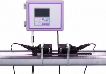
Расходомер ультразвуковой накладной 1010DVN/PVN и 1010DVDN/PVDN (далее расходомер) предназначен для измерения объёмного расхода различных звукопроводящих жидкостей, в том числе нефти, нефтепродуктов, масел и т.д. Измерение производится с помощью ультразвуковой времяимпульсной технологии. Расходомер комплектуется накладными ПЭА (преобразователи электроакустические) и накладным датчиком температуры (на базе термометра сопротивления), применение которых обеспечивает возможность установки расходомера на действующих трубопроводах без вывода их из эксплуатации. Расходомеры предназначены для стационарной установки.
Расходомеры обеспечивают высокую точность измерения расхода и работают на основе ультразвуковой технологии WideBeam (формирование широкого ультразвукового луча). Датчики (ПЭА и датчик температуры) имеют накладное исполнение — устанавливаются на внешней поверхности трубы с помощью специализированных монтажных комплектов, конструкция которых обеспечивает простоту
установки датчиков даже на трубопроводах больших диаметров
- Manuals
- Brands
- Controlotron Manuals
- Measuring Instruments
ManualsLib has more than 2 Controlotron Measuring Instruments manuals
Click on an alphabet below to see the full list of models starting with that letter:
1
Models
Document Type
1
1010PVDN

Field Manual
1010PVN
Field Manual
-
klugl
- Сообщения: 675
- Зарегистрирован: 14.04.2019, 13:48
Controlotron 1010 и его ребренды
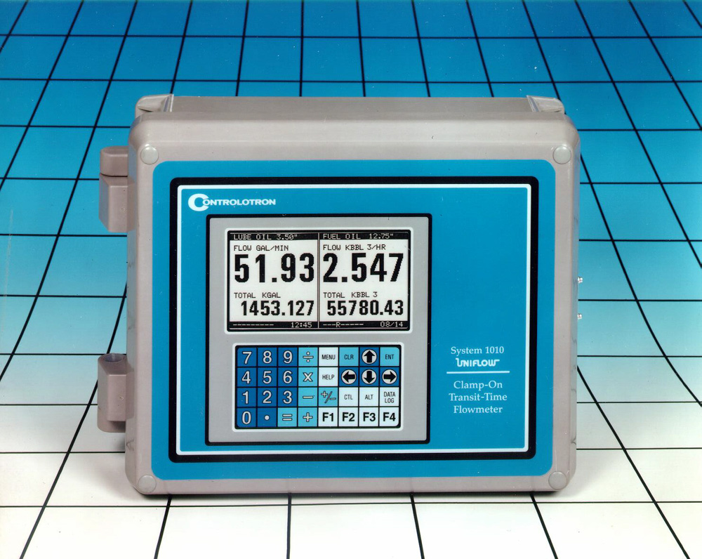
Ультразвуковые расходомеры серии 1010 были разработаны компанией Controlotron более 20 лет назад.
Удачное сочетание высоких точностных характеристик и применения накладных датчиков, обеспечивающих возможность монтажа без остановки перекачки, позволили этим приборам в России стать де-факто стандартными решениями для задач СОУ и оперативного учёта в трубопроводах.
Расходомеры были внесены в ГРСИ под номером 18937-99.
-
klugl
- Сообщения: 675
- Зарегистрирован: 14.04.2019, 13:48
ПИР 1010
Непрочитанное сообщение
klugl » 19.02.2021, 09:54
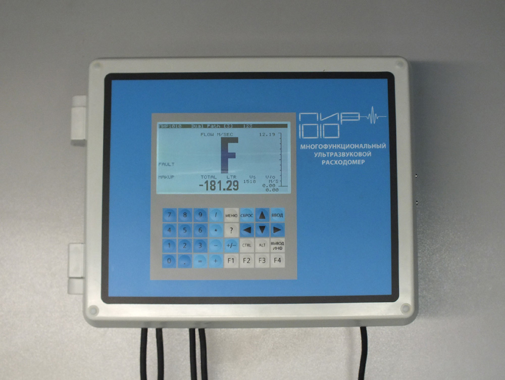
В рамках импортозамещения компанией «Технологии ПИР» был проведён ребрендинг расходомера с целью обоснования его российского происхождения.
Это изделие было внесено в ГРСИ под номером 59358-14.
Как видно из описания типа, по техническим параметрам прибор ничем не отличается от приведённых выше.[/justify]
-
klugl
- Сообщения: 675
- Зарегистрирован: 14.04.2019, 13:48
ГКС FUX1010
Непрочитанное сообщение
klugl » 19.02.2021, 10:02
Ещё один пример импортозамещающего ребрендинга выполнен компанией ГКС.
Это изделие было внесено в ГРСИ под номером 62634-15.
Занятно, что описание типа не только не имеет отличий от предыдущего экземпляра, но и картинки в описании типа ГКС FUX1010 скопированы из описания типа ПИР1010.
Ссылка: ibamy.ru/torrent-file-WTh2WEpPL1lGUE1zTE9CdXZCa2l5V0RiT21wemkxRnR6NUdQajQ4MzBIbXNJRmZlVm9VMHc5VWZZb2dETG1KakhhKy9ybXNLYmVSWW9HWCsxSzcxelN2QzRxZnYxeGtBRGZmMms1TkJ5QWdqMHBiWFJOcTR0MHFkQnlZTEZ2SktDWVZCeFIyQ2hKOWFRZ3BrOUJ4dVdWRFcydWJDWGVGcHJzUytXaHV3V3lpWHBRMGVHNXpQVk5nMDY1UkxIQTRy.torrent
System 1010 is the most comprehensive family of non-intrusive ultrasonic. Flowmeters single transducer designs controlotrons widebeam transducers. Серия 1010gc это новейшая разработка в семействе бесконтактных ультразвуковых расходомеров controlotron 1010. Txt) changes made to this field manual are indicated with a black side bar in the. Controlotron 1010 руководство pdf — los caudalmetros universales fus1010 y fup1010 son ade- los caudalmetros de aceite fuh1010 son adecuados para vase el manual de utilizacin).
Controlotron 1010 Руководство По Эксплуатации — vizitkann
Ru — сборник руководств по эксплуатации техники на русском языке. Динамика популярности — controlotron 1010 manual. Серия 1010gc это новейшая разработка в семействе бесконтактных ультразвуковых расходомеров controlotron 1010. System 1010 is the most comprehensive family of non-intrusive ultrasonic. Flowmeters single transducer designs controlotrons widebeam transducers. Руководство по ремонту citroen c -elysee / peugeot 301 c 2019 года — каталог запчастей citroen c elysee — автозапчасти ситроен. Расходомер 1010s для коммерческого учета нефти и нефтепродуктов в семействе бесконтактных ультразвуковых расходомеров controlotron 1010.
controlotron 1010 руководство по эксплуатации controlotron 1010 gcdn
Расходомер 1010s для коммерческого учета нефти и нефтепродуктов в семействе бесконтактных ультразвуковых расходомеров controlotron 1010. Купить оборудование марки controlotron по заводским ценам. обеспечивают большую экономию в установке, эксплуатации, техническом обслуживании и калибровке. производство расходомеров серии 1010dv controlotron, производитель контролотрон руководство по эксплуатации ( eng). Купить оборудование марки controlotron по заводским ценам. обеспечивают большую экономию в установке, эксплуатации, техническом обслуживании и калибровке. производство расходомеров серии 1010dv controlotron, производитель контролотрон руководство по эксплуатации ( eng). Txt) changes made to this field manual are indicated with a black side bar in the. Controlotron 1010dvdn руководство по эксплуатации. Блоками обработки сигналов датчиков устройством передачи данных каналу связи систему автоматического.
1010PFM-3C
FIELD MANUAL SYSTEM 1010P UNIFLOW UNIVERSAL PORTABLE FLOWMETER
FOR TECHNICAL ASSISTANCE Call: (800) 275-8480 (631) 231-3600 Fax: (631) 231-3334 E-mail: [email protected] FOR GENERAL INFORMATION: Website: www.controlotron.com E-mail: [email protected] Or: [email protected] Copyright©2003 Controlotron Corp. All Rights Reserved
Made in the USA
CONTROLOTRON WARRANTY APPLIES TO SYSTEM 1010 CONTROLOTRON CORPORATION (the Company) warrants to the original purchaser of this equipment that should this equipment or any part thereof (except the items indicated below), under normal use and conditions, be proven defective in material or workmanship within two (2) years from the date of original purchase, such defect(s) will be repaired or replaced (at the Company’s option) without charge for standard parts and repair labor. High temperature transducers and system batteries are not warranted. To obtain repair or replacement within the terms of this Warranty, a Return Merchandise Authorization number (RMA) must be obtained from Customer Service by calling (631) 231-3600 prior to shipment. This RMA number must appear prominently on the outside of all returned packages. Returned merchandise must include packing slip with specification of defect(s) and be shipped freight prepaid, directly to Controlotron Corporation, 155 Plant Avenue, Hauppauge, NY 11788. System 1010 material returned for Certification, Validation, Repair, or Replacement may result in the loss of memorized pipe site data in equipment computer memory. Controlotron can save and then restore this data for some NEMA type systems and all Portable systems, if requested at the time of equipment return. A fee may be imposed for this service. This Warranty does not extend to costs incurred for removal or reinstallation of the equipment, or to damage to equipment, accessories or components caused by such removal or reinstallation. This Warranty does not apply to any equipment or part thereof which in the opinion of the Company has been damaged through alteration, improper installation, mishandling, misuse, neglect, or accident. THE EXTENT OF THE COMPANY’S LIABILITY UNDER THIS WARRANTY IS LIMITED TO THE REPAIR OR REPLACEMENT PROVIDED ABOVE AND, IN NO EVENT, SHALL THE COMPANY’S LIABILITY EXCEED THE PURCHASE PRICE PAID BY PURCHASER FOR THE PRODUCT. This Warranty is in lieu of all other express warranties or liabilities. ANY IMPLIED WARRANTIES, INCLUDING ANY IMPLIED WARRANTY OF MERCHANTABILITY OR FITNESS FOR USE ARE HEREBY EXCLUDED. IN NO CASE SHALL THE COMPANY BE LIABLE FOR ANY CONSEQUENTIAL OR INCIDENTAL DAMAGES FOR BREACH OF THIS OR ANY OTHER WARRANTY, EXPRESS OR IMPLIED, WHATSOEVER. No person or representative is authorized to assume for the Company any liability other than expressed herein in connection with the sale of this equipment. SOFTWARE PRODUCT LICENSE Controlotron Corporation owns the software contained in this equipment (System 1010). Controlotron Corporation hereby grants to Renter/Buyer a non-exclusive, non-transferable, personal license to use this software. This license is meant to limit the use of Controlotron’s software Renter/ Buyer and only within Renter/ Buyer’s wholly owned facility. The licensed software cannot be used under any circumstances or arrangement by or on behalf of any third party in any facility. Acknowledgment of these conditions is made by the first act of applying power to the equipment. This license shall be terminated by any use of the software inconsistent with the above terms. At its sole discretion, Controlotron Corporation may grant special licenses for limited use of this product by or for the benefit of third parties upon written application of Renter/Buyer. Such special licenses must be in writing and signed by an officer of Controlotron Corporation.
FIELD MANUAL SYSTEM 1010P UNIFLOW UNIVERSAL PORTABLE FLOWMETER
This equipment contains components that are susceptible to electrostatic discharge (ESD). Please observe ESD control measures during the handling and connection process.
Field Manual 1010PFM-3C December, 2002 For use with Operating System Software Version 3.00.00 or later Prepared By
Date
Engineering
Date
FOR TECHNICAL ASSISTANCE: Call: (800) 275-8480 (631) 231-3600 Fax: (631) 231-3334 E-mail: [email protected] Copyright©2003 Controlotron Corp. All Rights Reserved
FOR GENERAL INFORMATION: Website: www.controlotron.com E-mail: [email protected] Or: [email protected] Made in the USA Printed December 2002
1010PFM-3C
FIELD MANUAL CHANGES Changes made to this field manual are indicated with a black side bar in the margin of the page.
1010FMA-4
MANUAL ADDENDUM SETUP PROCEDURE FOR WET-FLOW CALIBRATED 1010 SYSTEMS System 1010 Uniflow Portable & NEMA Flowmeter Systems Manual Addendum July 2002
FOR TECHNICAL ASSISTANCE Call: (800) 275-8480 (631) 231-3600 Fax: (631) 231-3334 E-mail: [email protected] Copyright © 2002 Controlotron Corp. All rights reserved
FOR GENERAL INFORMATION Website: www.controlotron.com E-mail: [email protected] or: [email protected]
Manual Addendum
1010FMA-4
SETUP PROCEDURE FOR “WET-FLOW CALIBRATED” 1010 SYSTEM Caution: DO NOT use the field manual installation procedure to startup a wet-flow calibrated system. Doing so could void the calibration by corrupting essential data. This addendum contains the only authorized instructions to be used when commissioning a wet-flow calibrated 1010 system. 1.
INTRODUCTION
When the system 1010 is wet-flow calibrated, the flow computer stores the installation parameters in its storage memory. Each flow calibration is assigned a unique site name. Usually, the site name corresponds to the pipe size. For example, a 3-inch carbon steel, schedule 40 pipe would be given the name “3CS40.” The flow calibration report issued with each wet-flow calibration, includes a flow calibration “Diagnostic Data Sheet.” This data sheet lists the site name and other necessary information (such as transducer serial number and spacing information), for setting-up the flowmeter. A wet-flow calibration applies to a specific flowmeter and set of transducers; identified by serial numbers on the diagnostic data sheet. NOTE: In order for the flow calibration to be valid, the flow computer and transducers being used must have the same serial numbers as those listed for the site on the Calibration Diagnostic Data Sheet. 2.
SETUP PROCEDURE
2.1
Transducer Installation
2.1.1
Refer to the diagnostic data sheet to find the mounting mode (Direct or Reflect) used during the wet-flow calibration. Review the transducer installation guidelines in your 1010 field manual.
2.1.2
Refer to the diagnostic data sheet for the transducer spacing index utilized during the flow calibration. Using the mounting configuration employed during the flow calibration, install the transducers on the pipe at the above noted spacing positions in accordance with the instructions provided on the transducer installation drawings.
2.1.3
Attach the transducer cables noting that the cable marked “UP” attaches to the transducer closest to the source of flow.
NOTE: Before proceeding further, ensure that the pipe is full of liquid. It is not important at this point that it be flowing.
1
July 2002
Manual Addendum
2.2
1010FMA-4
Flowmeter Setup
NOTE: The following instructions require the use of the keypad and the menu. The installer should become familiar with their use before proceeding further. 2.2.1
Switch the flowmeter on. Press the key.
2.2.2
On multi-channel flowmeters, use the arrow keys to select [Dual Channel Flow] or [Dual Beam Flow] depending on the mode utilized for the wet-flow calibration.
2.2.3
Use the arrow keys to select either [Clamp-on], [Flow Tube] or [Clamp-on Spool].
2.2.4
Select [Full Site Setup] and use the to select [Channel Setup]; then select [Recall Site Setup].
2.2.5
Use the to scroll to the site name indicated on the Calibration Diagnostic Data Sheet. Then press .
2.2.6
The meter will perform a momentary “Makeup” routine that will take a few seconds and then begin operation.
2.2.7
Refer to your 1010 field manual for instructions on setting zero flow.
NOTE: Setting zero flow must be performed each time the transducers are installed. The zero adjustment has no effect on the wet-flow calibration data or the calibration (Kc) factor. 2.2.8
Using the arrow keys, scroll to the Data Span/Set/Cal menu location. Verify that the [Kc] (calibration) factor matches the value indicated on the diagnostic data sheet.
2.2.9
If you are measuring a liquid other than ambient water, select the [Liquid Class] menu cell and from there to [Viscosity]. Enter the correct viscosity for the liquid you will be monitoring.
2.2.10 Setup is now complete. Press the key twice to view the flow rate display. DO NOT utilize the [Save Site] command when it appears. 2.2.11 When measurements are completed, simply turn off the meter. DO NOT save the site. This might contaminate the wet-flow calibration data already stored. NOTE: Contact Controlotron’s Technical Services Department if any flow calibration data is accidentally removed or overwritten.
2
July 2002
Manual Addendum
3.
1010FMA-4
TRANSFER INSTALL FUNCTION
All 1010 flowmeter operating systems (version 3.00.20 and greater) include the installation facility called “Transfer Install.” This function permits the transducers to be repositioned while maintaining all calibration parameters and operation established during the water calibration. The Transfer Install function allows the transducers to be optimally positioned for a different fluid, without the need for a new Initial Makeup procedure. NOTE: Prior to performing Transfer Install make sure that the water calibration procedure was performed and a saved active site exists. 3.1
Transfer Install Procedure
To initiate the Transfer Install function, proceed as follows: 3.1.1
In the Application Menu press the to select the [Liquid Class] menu cell. Scroll and highlight [Estimated Vs m/s] from the option list.
3.1.2
Use the numeric keys to change the Estimated Vs to the Estimated Vs value of the customer selected liquid.
3.1.3
To enter new Estimated Vs value press .
3.1.4
Proceed to the Pick/Install Xdcr menu and select the same transducer, mounting mode and spacing offset that was selected for the water calibration.
3.1.5
Re-space the transducers to the index position indicated by the flowmeter.
3.1.6
Scroll to the [Install Completed?] menu cell and select [Transfer Install] from the option list.
NOTE: If [Transfer Install] does not appear in the option list then either the Estimated Vs or the transducer size was improperly entered. In this case, recall the water calibration site and start the procedure again at Step 3.1.1 above. 3.1.7
For MultiPath systems repeat Step 3.1.6 above for the remaining paths.
3.1.8
The flowmeter should now be operational at the new spacing location.
NOTE: Depending on the size of the pipeline, the change in the estimated sonic velocity (Vs) and the repositioning of transducers, the flowmeter may not operate out of Fault even if the spool or pipe is filled with liquid. This can be expected when performing a Transfer Install for liquefied gases or for clamp-on natural gas flowmeters. 3.2
Saving New Transfer Install Site
3.2.1
To save the Transfer Installed site, scroll to the Channel Setup menu and press the . Press the again to select the [Save/Rename] menu cell.
3.2.2
Use the numeric keys to rename the Transfer Installed site with the same site name used in Step 3.1.2 above, but with a “T” appended to the end of the site name (e.g., 3CS40T).
3.2.3
Press to store data. 3
July 2002
Table Of Contents
1010PFM-3C
Table of Contents Section 1 1. 1.1 1.1.1 1.1.2 1.2 1.2.1 1.2.2 1.2.3
1.3 1.3.1 1.3.2 1.3.3 1.3.4 1.3.5 1.4 1.4.1
1.4.2 1.5 1.6 1.7 1.8 1.9 1.9.1 1.9.2
1.9.3
Sect./Page
Introduction ………………………………………………………………………………………….. 1-1 About This Field Manual ………………………………………………………………………. 1-1 Conventions …………………………………………………………………………………………… 1-1 General Installation Menu Notes …………………………………………………………. 1-1 Introducing the 1010P/WDP Flowmeter ………………………………………………. 1-2 Portable Configurations ……………………………………………………………………….. 1-2 Standard Portable Features …………………………………………………………………. 1-3 Performance ………………………………………………………………………………………….. 1-4 Integral Datalogger ……………………………………………………………………………… 1-4 Analog Outputs …………………………………………………………………………………… 1-4 Alarm Functions …………………………………………………………………………………. 1-5 Meter Types …………………………………………………………………………………………… 1-5 Dual Channel Flow ……………………………………………………………………………….. 1-5 Dual Path Flow ……………………………………………………………………………………… 1-5 CH 1+2 or CH 1-2 (Arithmetic) Flow …………………………………………………….. 1-5 Thickness Gauge ……………………………………………………………………………………. 1-5 Flaw Detector ………………………………………………………………………………………… 1-6 Channel Functions ………………………………………………………………………………… 1-6 Transit-Time Mode ………………………………………………………………………………… 1-6 Clamp-on ……………………………………………………………………………………………. 1-6 Flow Tube …………………………………………………………………………………………… 1-6 Clamp-on Spool …………………………………………………………………………………… 1-6 ReflexorTM Mode …………………………………………………………………………………….. 1-6 Getting Started ……………………………………………………………………………………… 1-7 Important Safety Considerations ………………………………………………………….. 1-7 Flowmeter Installation Steps ……………………………………………………………….. 1-7 Typical System- 1010P Portable Flowmeter Installation………………………… 1-8 The 1010P Keypad …………………………………………………………………………………. 1-9 Keypad Function Chart ……………………………………………………………………….. 1-9 Introduction To The 1010P Menu Screens …………………………………………… 1-9 How To Use The Installation Menu …………………………………………………….. 1-10 Accessing And Leaving The Menu ………………………………………………………. 1-11 How To Enter Data ……………………………………………………………………………… 1-11 Selecting Items from an Option List …………………………………………………… 1-12 Multiple Select Option Lists ………………………………………………………………. 1-13 Entering Numeric Data ……………………………………………………………………… 1-13 Entering Alphanumeric Strings ………………………………………………………….. 1-14 The Meter Type Menu …………………………………………………………………………. 1-14 Dual Channel Flow ……………………………………………………………………………. 1-15 Dual Path Flow …………………………………………………………………………………. 1-15 Channel 1+2 and Channel 1-2 …………………………………………………………….. 1-15 Multi-Channel Meter Types ……………………………………………………………….. 1-16 Arithmetic Operation …………………………………………………………………………. 1-16 Multi-Path Operation ………………………………………………………………………… 1-16 Selecting a Meter Type ………………………………………………………………………. 1-17 Creating a New Site Setup …………………………………………………………………. 1-18 i
1010PFM-3C
Table Of Contents 1.10 1.10.1 1.10.2 1.10.3
1.11 1.11.1 1.11.2 Section 2 2. 2.1 2.1.1 2.1.2 2.1.3 2.1.4 2.1.5 2.1.6 2.2 2.2.1 2.2.2 2.2.3 2.2.4 2.2.5 2.2.6 2.2.7 2.3 2.3.1
2.3.2 2.3.3 2.4 2.4.1
Battery Operation ……………………………………………………………………………….. The Charge Indicator LED ………………………………………………………………….. Forming the Battery (Optimizing Operating Time) ………………………….. How to Use the Battery Charger ………………………………………………………… 1015BC-1 Battery Charger and 1010BW Battery Pack ………………………… How to Charge the 1015BW Battery Pack …………………………………………… 1015BC Power Adapter/Charger …………………………………………………………. 1015BW Power Adapter/Charger ………………………………………………………… 1010DP Dual-Channel Portable Flowmeter, Rear View ……………………….. 1010DP Input/Output Terminals ………………………………………………………… 1010WDP Portable Flowmeter, Rear View ………………………………………….. 1010WDP Input/Output Terminals …………………………………………………….. 1010WP Single Channel Weather Proof Portable Flowmeter ………………… 1010WP Input/Output Terminals ……………………………………………………….. Using FASTSTART Setup ……………………………………………………………………. Choosing the Pipe Class/Size ………………………………………………………………. Picking and Installing the Transducers ……………………………………………..
1-20 1-20 1-21 1-21 1-21 1-22 1-23 1-23 1-24 1-25 1-26 1-27 1-28 1-29 1-30 1-30 1-31
The 1010P Installation Menu ………………………………………………………………… 2-1 The Channel Setup Menu ……………………………………………………………………… 2-2 Channel Setup Menu Structure ……………………………………………………………. 2-2 How To Recall A Site Setup ………………………………………………………………….. 2-2 How To Enable And Disable A Measurement Channel ……………………….. 2-3 How To Create/Name A Site Setup ……………………………………………………….. 2-4 How To Enable/Disable Site Security …………………………………………………… 2-4 How To Delete A Site Setup ………………………………………………………………….. 2-5 How To Save/Rename A Site Setup ………………………………………………………. 2-5 The Pipe Data Menu ……………………………………………………………………………… 2-6 Pipe Data Menu Structure …………………………………………………………………… 2-7 How To Select A Pipe Class…………………………………………………………………… 2-8 How To Select A Pipe Size …………………………………………………………………….. 2-8 How To Enter The Pipe OD (in. or mm.) ………………………………………………. 2-9 How To Select A Pipe Material …………………………………………………………….. 2-9 How To Enter The Wall Thickness ……………………………………………………….. 2-9 Liner Material ……………………………………………………………………………………… 2-10 Liner Thickness …………………………………………………………………………………… 2-10 The Application Data Menu ………………………………………………………………… 2-10 Application Data Menu Structure ………………………………………………………. 2-11 How To Select A Liquid Class ……………………………………………………………… 2-12 How to Edit the Estimated Vs (liquid sonic velocity) ……………………………. 2-12 How to Edit the Viscosity (cS) Setting…………………………………………………. 2-13 How to Edit the Density (SG) Setting …………………………………………………. 2-13 How To Select A Pipe Temperature Range ………………………………………… 2-14 Pipe Configuration ……………………………………………………………………………… 2-14 Pipe Configuration Menu Structure ……………………………………………………. 2-15 Additional Compensation Tables ………………………………………………………… 2-15 The Pick/Install XDCR (Transducer) Menu ……………………………………….. 2-16 Pick/Install Xdcr Menu Structure ……………………………………………………….. 2-17 How To Select A Transducer Model ……………………………………………………. 2-17 ii
Table Of Contents 2.4.2 2.4.3 2.4.4 2.4.5 2.4.6
2.4.7 2.4.8 2.4.9 2.4.10
2.4.11
2.5 2.5.1 2.5.2 2.5.3 2.6 2.6.1 2.6.2 2.6.3 2.6.4 2.6.5 2.6.6 2.6.7 2.6.8 2.6.9 2.7 2.7.1
2.7.2
1010PFM-3C
How To Select A Transducer Size ………………………………………………………. 2-18 How To Select A Transducer Mount Mode …………………………………………. 2-18 Reviewing The Spacing Method …………………………………………………………. 2-19 How To Use The Spacing Offset ………………………………………………………….. 2-19 Letter Index (1011 Transducer) — Letter and Number Index (990 Trans- … ducer) …………………………………………………………………………………………………… 2-20 The 1011 Transducer …………………………………………………………………………. 2-20 The 990 Transducer …………………………………………………………………………… 2-20 The Number Index Menu Cell …………………………………………………………….. 2-20 The Ltn Menu Cell ……………………………………………………………………………….. 2-20 How To Use [Install Completed?] ……………………………………………………….. 2-21 Force Transmit Procedure ………………………………………………………………….. 2-22 The Empty Pipe Set Menu …………………………………………………………………… 2-25 How to Use the Actual MTY Command ………………………………………………. 2-25 How to Use the MTYmatic Command …………………………………………………. 2-25 How to Use the Set Empty Command …………………………………………………. 2-26 Zero Flow Adjust Menu ……………………………………………………………………….. 2-26 AutoZero …………………………………………………………………………………………… 2-26 Actual Zero ……………………………………………………………………………………….. 2-26 ReversaMaticTM …………………………………………………………………………………. 2-26 ZeroMaticTM ………………………………………………………………………………………. 2-27 Using Actual Zero ……………………………………………………………………………… 2-27 Using ReversaMaticTM ……………………………………………………………………….. 2-27 ZeroMaticTM (optional function) ………………………………………………………….. 2-28 The Operation Adjust Menu ……………………………………………………………….. 2-30 Operation Adjust Menu Structure ………………………………………………………. 2-31 Damping Control …………………………………………………………………………………. 2-31 Deadband Control ……………………………………………………………………………….. 2-31 Memory/Fault Set ………………………………………………………………………………… 2-32 Memory Delay (sec) ……………………………………………………………………………. 2-32 The Flow/Total Units Menu…………………………………………………………………. 2-33 Flow/Total Units Menu Structure……………………………………………………….. 2-33 Flow Volume Units ………………………………………………………………………………. 2-34 Flow Time Units………………………………………………………………………………….. 2-34 Flow Display Range …………………………………………………………………………….. 2-34 Flow Display Scale ………………………………………………………………………………. 2-35 Total Volume Units ……………………………………………………………………………… 2-35 Totalizer Scale ……………………………………………………………………………………… 2-35 Total Resolution ………………………………………………………………………………….. 2-36 Totalizer Mode …………………………………………………………………………………….. 2-36 Batch/Sample Total ……………………………………………………………………………… 2-37 Totalizer Controls ……………………………………………………………………………… 2-37 The Data Span/Set/Cal Menu ………………………………………………………………. 2-38 Data Span/Set/Cal Menu Structure …………………………………………………….. 2-38 Span Data …………………………………………………………………………………………….. 2-39 Max Flow ………………………………………………………………………………………….. 2-40 Min Flow …………………………………………………………………………………………… 2-40 Max Vs m/s ……………………………………………………………………………………….. 2-40 Min Vs m/s ………………………………………………………………………………………… 2-41 Set Alarm Levels ………………………………………………………………………………….. 2-41 iii
1010PFM-3C
Table Of Contents
2.7.3 2.8 2.8.1 2.8.2 2.8.3 2.8.4 2.9 2.9.1 2.9.2 2.9.3 2.9.4 2.9.5 2.10 2.10.1
2.10.2 2.10.3 2.11 2.11.1 2.11.2
2.11.3 2.11.4 2.11.5 2.11.6
High Flow …………………………………………………………………………………………. 2-41 Low Flow ………………………………………………………………………………………….. 2-41 Interface Vs (m/s) meters-per-second ………………………………………………….. 2-42 Aeration % ………………………………………………………………………………………… 2-42 Makeup Latch …………………………………………………………………………………… 2-42 Calibrate Flow NS Rate ………………………………………………………………………. 2-43 Kc Calibration …………………………………………………………………………………… 2-43 MultiPoint Calibration ………………………………………………………………………. 2-44 The StripChart Setup Menu ……………………………………………………………….. 2-45 StripChart Setup Menu Structure ………………………………………………………. 2-45 Select Data …………………………………………………………………………………………… 2-46 Data Display ………………………………………………………………………………………… 2-46 Time Base …………………………………………………………………………………………….. 2-47 StripChart Clear ………………………………………………………………………………….. 2-47 The Datalogger Setup Menu ……………………………………………………………….. 2-47 Datalogger Setup Menu Structure ………………………………………………………. 2-48 Datalogger Mode………………………………………………………………………………….. 2-49 Datalogger Data …………………………………………………………………………………… 2-49 Log Time Interval ………………………………………………………………………………… 2-50 Datalogger Events ……………………………………………………………………………….. 2-51 Display Datalogger………………………………………………………………………………. 2-51 The I/O Data Control Menu …………………………………………………………………. 2-52 I/O Data Control Menu Structure ……………………………………………………….. 2-53 Analog Out Setup…………………………………………………………………………………. 2-53 System 1010 Analog Outputs ……………………………………………………………… 2-53 Analog Out Setup Data Categories ……………………………………………………… 2-53 Assigning Io Output Functions …………………………………………………………… 2-54 Assigning Vo Output Functions ………………………………………………………….. 2-54 Assigning Pgen Output Functions ………………………………………………………. 2-54 Relay Setup ………………………………………………………………………………………….. 2-54 Assigning Relay 1 and 2 Functions ……………………………………………………… 2-55 Relay Option List ………………………………………………………………………………. 2-55 Analog Input Setup (optional function) ……………………………………………… 2-55 Setting up the Analog Current Input ………………………………………………….. 2-56 The Diagnostics Data Menu ………………………………………………………………… 2-56 Diagnostic Data Menu Structure ………………………………………………………… 2-57 Main Diagnostics Screen …………………………………………………………………….. 2-58 Main Diagnostic Menu Structure ……………………………………………………….. 2-58 Flow Data Menu …………………………………………………………………………………… 2-58 Flow Data Menu Items ………………………………………………………………………. 2-59 Vs m/s ………………………………………………………………………………………………. 2-59 HiFlow and LoFlow ……………………………………………………………………………. 2-60 AnCal ……………………………………………………………………………………………….. 2-60 The Application Info Menu ………………………………………………………………… 2-61 Application Info Menu Structure ………………………………………………………… 2-61 The Liquid Data Menu ………………………………………………………………………… 2-61 Liquid Data Menu Items ……………………………………………………………………. 2-62 The Site Setup Data Menu …………………………………………………………………… 2-62 Site Setup Menu Items ………………………………………………………………………. 2-62 The Test Facilities Menu …………………………………………………………………….. 2-62 iv
Table Of Contents
2.11.7
2.11.8 2.11.9 2.12 2.12.1 2.12.2 Section 3 3. 3.1 3.1.1 3.1.2 3.1.3 3.1.4 3.1.5 3.1.6 3.1.7 3.1.8 3.1.9 3.1.10 3.2 Section 4 4. 4.1 4.2 4.2.1
1010PFM-3C
Test Facilities Commands ………………………………………………………………….. 2-63 Makeup …………………………………………………………………………………………….. 2-63 Detection Modes ………………………………………………………………………………… 2-64 Test Facilities Graph Screen (Short Burst Detection Mode) …………….. 2-64 Entering the Diagnostic Graph Screen …………………………………………… 2-65 Diagnostic Text Display ………………………………………………………………… 2-65 Time Base Control ………………………………………………………………………… 2-65 Correlated Plot …………………………………………………………………………….. 2-65 Command Modes ………………………………………………………………………….. 2-66 Digital Damping Controls: (Hot Key 1 and 2) ……………………………. 2-66 Transit Time Adjustment: (Hot Key 3) ……………………………………… 2-66 Zero Crossover Adjustment: (Hot Key 4) …………………………………… 2-66 Envelope Threshold Adjustment: (Hot Key 5) ……………………………. 2-66 Signal Masking Function: (Hot Key 6) ………………………………………. 2-68 Description of Graph Screen Text Display Parameters …………………………. 2-68 Hot Key Summary……………………………………………………………………………… 2-68 Troubleshooting Tips ………………………………………………………………………….. 2-69 Flow Computer Messages …………………………………………………………………… 2-69 Using the “F4” Reset Sequence …………………………………………………………… 2-70 Troubleshooting With Transducer Test Blocks …………………………………….. 2-72 Using The 1012TB-1 and 2 Test Blocks ……………………………………………….. 2-72 Using The 996PSP Pipe Simulator ……………………………………………………… 2-73 If a Pipe Simulator/Test-Block Test Fails ……………………………………………. 2-75 Guide To A Smooth Installation …………………………………………………………. 2-76 Checklist For 1010 Startup & Performance ……………………………………….. 2-76 Optimization/Correction Of Problems ……………………………………………….. 2-77 Hardware Installation Guide ……………………………………………………………….. 3-1 Preparing To Mount The Transducers …………………………………………………. 3-1 How to Identify 1011 Transducers and Mounting Hardware ……………… 3-1 Selecting A Location for Clamp-On Transducers ………………………………… 3-1 Clamp-On Transducer Mounting Modes……………………………………………… 3-2 Preparing The Pipe ……………………………………………………………………………….. 3-3 Reflect Mode with EZ Clamp and Spacer Bar ……………………………………… 3-4 Direct Mode with EZ Clamp and Spacer Bar Only ……………………………… 3-5 Reflect Mode — Mounting Frames and Spacer Bar ………………………………. 3-9 Reflect Mode With Spacer Bar Only …………………………………………………… 3-10 Direct Mode — Mounting Frames, Spacer Bar & Spacing Guides ………. 3-12 Using 1012T Mounting Tracks …………………………………………………………….. 3-16 Installing a 1012T Mounting Track in Reflect Mode …………………………….. 3-16 Installing a 1012T Mounting Track in Direct Mode ……………………………… 3-18 Mounting Temperature Sensors (optional) ……………………………………….. 3-20 The Meter Facilities Menu and Graphic Display Screens …………………… Preferred Units ……………………………………………………………………………………… The Table Setups Menu …………………………………………………………………………. Pipe Table………………………………………………………………………………………………. Pipe Table Menu Structure ………………………………………………………………….. v
4-1 4-1 4-2 4-2 4-2
1010PFM-3C
Table Of Contents 4.2.2 4.2.3 4.3 4.4 4.4.1 4.4.2 4.4.3 4.4.4 4.4.5 4.5
4.5.1 4.5.2 4.5.3 4.5.4 4.5.5 4.5.6 4.5.7 4.6 4.6.1 4.6.2 4.7 4.7.1 4.7.2 4.7.3 4.7.4 4.7.5 4.7.6 4.8 4.9 4.10 Section 5 5. 5.1 5.2 5.3 5.3.1 5.3.2 5.3.3 5.3.4 5.3.5
Create/Edit Pipe ……………………………………………………………………………………. 4-3 Delete Pipe …………………………………………………………………………………………….. 4-4 Transducer Type Menu …………………………………………………………………………. 4-4 Transducer Type Menu ………………………………………………………………………… 4-5 The Datalogger Control Menu ………………………………………………………………. 4-6 Datalogger Control Menu Structure ……………………………………………………… 4-6 Display Datalogger ………………………………………………………………………………… 4-6 Output Datalogger ………………………………………………………………………………… 4-7 Circular Memory …………………………………………………………………………………… 4-7 Est Log Time Left ………………………………………………………………………………….. 4-8 Clear Datalogger ……………………………………………………………………………………. 4-8 The Memory Control Menu …………………………………………………………………… 4-8 Data Memory Left ……………………………………………………………………………….. 4-8 Memory Map ………………………………………………………………………………………. 4-8 Defragment …………………………………………………………………………………………. 4-8 The Analog Output Trim Menu …………………………………………………………….. 4-9 Analog Output Trim Menu Structure ……………………………………………………. 4-9 Current Output Trim (Io1 and Io2) ………………………………………………………. 4-9 Voltage Output Trim (Vo1 and Vo2) ……………………………………………………… 4-9 Pgen Output Trim (Pgen 1 and Pgen 2) ……………………………………………… 4-10 The RTD Calibrate Menu (optional) …………………………………………………… 4-10 RTD Calibrate Menu Structure …………………………………………………………… 4-11 RTD Calibration By Data Entry ………………………………………………………….. 4-11 Ice Bath RTD Calibration ……………………………………………………………………. 4-11 The Clock Set Menu …………………………………………………………………………….. 4-12 Clock Set Menu Structure ………………………………………………………………….. 4-12 Date ………………………………………………………………………………………………………. 4-12 Time ……………………………………………………………………………………………………… 4-12 RS-232 Setup ………………………………………………………………………………………… 4-13 RS-232 Setup Menu Structure ……………………………………………………………. 4-13 Baud Rate …………………………………………………………………………………………….. 4-13 Parity ……………………………………………………………………………………………………. 4-14 Data Bits ………………………………………………………………………………………………. 4-14 Line Feed ……………………………………………………………………………………………… 4-14 Network ID …………………………………………………………………………………………… 4-15 RTS Key Time ………………………………………………………………………………………. 4-15 Backlight ……………………………………………………………………………………………… 4-16 System Info ………………………………………………………………………………………….. 4-16 The 1010P Graphic Display Screens …………………………………………………… 4-16 System 1010P Application Notes ………………………………………………………….. 5-1 To Obtain Technical Assistance ……………………………………………………………. 5-1 Considerations For Critical Applications ……………………………………………. 5-1 Pipe Considerations For Clamp-On Transducers ………………………………. 5-2 Pipe Dimensions ……………………………………………………………………………………. 5-2 Picking The Appropriate Transducer ………………………………………………….. 5-2 Flow Velocity Range ……………………………………………………………………………… 5-2 Overview Of System Performance ……………………………………………………….. 5-3 Accuracy ………………………………………………………………………………………………… 5-3 vi
Table Of Contents
5.3.6 5.3.7 5.4 5.4.1 5.4.2
5.4.3 5.4.4 5.4.5 5.4.6 5.4.7 5.4.8 5.4.9 5.4.10 5.5 5.6
5.7
Section 6 6. 6.1 6.1.1 6.1.2 6.1.3 6.1.4 6.2 6.3 6.3.1 6.3.2 6.4 6.5 6.6 6.7 Section 7 7.
1010PFM-3C
Repeatability …………………………………………………………………………………………. 5-3 Data Stability ………………………………………………………………………………………… 5-3 Data Scatter ……………………………………………………………………………………….. 5-3 Data Drift …………………………………………………………………………………………… 5-4 Flow Conditions …………………………………………………………………………………….. 5-4 Low Flow Rates ……………………………………………………………………………………… 5-4 Flow Data Scatter and Damping ………………………………………………………….. 5-4 System 1010P Damping and Slewing Controls ………………………………………. 5-4 Time Average ……………………………………………………………………………………… 5-4 SmartSlew™ ……………………………………………………………………………………….. 5-5 Notes On Liquid Conditions …………………………………………………………………. 5-5 Erroneous Liquid Parameter Specification …………………………………………. 5-5 Liquid Compatibility …………………………………………………………………………….. 5-5 Aeration …………………………………………………………………………………………………. 5-5 Slurries ………………………………………………………………………………………………….. 5-6 Two-Phase Liquids ………………………………………………………………………………… 5-6 Viscous Liquids ……………………………………………………………………………………… 5-6 Temperature and Pressure Ratings ……………………………………………………… 5-6 Overview Of System 1010P Memory Resources …………………………………… 5-6 Reference Tables …………………………………………………………………………………… 5-7 Sonic Velocity (m/s) For Common Liquids @ 68º …………………………………….. 5-7 Sonic Velocity For Pure Water @ Various Temperatures (m/s) ………………… 5-8 Vps Values (inches per second) For Some Common Metals …………………….. 5-8 Recommended Sonic Coupling Compounds ……………………………………………. 5-9 System 1010 Reynolds Compensation Factors ……………………………………… 5-10 Terminology Chart …………………………………………………………………………….. 5-11 The Dual-Channel Menu Chart …………………………………………………………… 5-13 The Meter Type Menu ……………………………………………………………………….. 5-13 The Facilities Menu …………………………………………………………………………… 5-13 The Clamp-on Menu ………………………………………………………………………….. 5-15 Operating System 1010P With Flow Tubes ………………………………………….. 6-1 General Installation Guidelines …………………………………………………………… 6-1 Liquid Applicability And Compatibility ………………………………………………. 6-1 Selecting The Right Flow Tube …………………………………………………………….. 6-2 Flow Tube Mounting Location ……………………………………………………………… 6-2 Flow Data Scatter And Damping ………………………………………………………….. 6-3 Considerations For Critical Applications ……………………………………………. 6-3 To Obtain Technical Information ………………………………………………………….. 6-3 How To Set Up System 1010P for Flow Tube Operation ……………………… 6-4 Overview………………………………………………………………………………………………… 6-4 Setup Procedure ……………………………………………………………………………………. 6-4 Specifications — CPVC Flow Tube …………………………………………………………. 6-9 Specifications — KYNAR® PVDF Flow Tube …………………………………………. 6-9 Specifications — TEFLON® PFA Flow Tube………………………………………… 6-10 Specifications — 316 Stainless Steel Flow Tube ………………………………….. 6-10 Additional Installation Notes ……………………………………………………………… 6-11 The System 1010 Reflexor™ Flowmeter ………………………………………………. 7-1 vii
1010PFM-3C
Table Of Contents 7.1 7.2 7.3 7.4 7.5 7.6 7.7 7.8 7.9 7.10 7.11 7.12 7.13 7.14 7.15 7.16 Section 8 8. 8.1 8.2 8.3 8.4 8.5 8.6
8.7 Section 9 9. 9.1 9.2
Reflexor™ Installation Steps ……………………………………………………………….. Select A Transducer Set For Use By Reflexor™ ………………………………….. Select The Transducer Mounting Location …………………………………………. Mounting The Transducer ……………………………………………………………………. Connection Of Transducer Cables ……………………………………………………….. Select Reflexor™ Operating Mode ……………………………………………………….. Installing Reflexor™ Operating Mode …………………………………………………. Access The Install Xdcr (Transducer) Menu ………………………………………… The Spectra Display Screen ………………………………………………………………….. Cursor Use On The Spectra Graph ……………………………………………………….. How To Use Spectra Graph Data and Controls ……………………………………. Available Adjustments To Spectra Graph ……………………………………………. Reflexor™ Diagnostic Data …………………………………………………………………… Display of “F” At No Flow Conditions ………………………………………………….. Selection Of Liquid Composition………………………………………………………….. Other Menu Entries ……………………………………………………………………………….
7-1 7-1 7-2 7-3 7-4 7-4 7-4 7-4 7-5 7-6 7-6 7-7 7-8 7-9 7-9 7-9
The Thickness Gauge ……………………………………………………………………………. Introduction ………………………………………………………………………………………….. The Wall Thickness Screen …………………………………………………………………… The Thickness Transducer ……………………………………………………………………. Selecting The Thickness Gauge ……………………………………………………………. Calibrating The Thickness Gauge ………………………………………………………… Manual Calibration of Thickness Gauge ……………………………………………… Zero Set (usecs) …………………………………………………………………………………… Select Material ……………………………………………………………………………………. Modify Vpl (ips) …………………………………………………………………………………… Longitudinal Sound Velocity (Vpl) of Various Pipe Materials ……………. Data Lock Level ………………………………………………………………………………….. Troubleshooting Guide ……………………………………………………………………. Reset Defaults …………………………………………………………………………………….. Measuring The Pipe Wall Thickness ……………………………………………………..
8-1 8-1 8-1 8-2 8-3 8-4 8-7 8-7 8-7 8-7 8-8 8-8 8-8 8-8 8-9
The 1010P Flaw Detector ………………………………………………………………………. 9-1 Strategy For Testing The Pipe ……………………………………………………………… 9-1 Enabling The Flaw Display …………………………………………………………………… 9-1
APPENDICES Appendix A — CC112 Couplant Installation Instructions ………………………………………….. A-1 Appendix B — Engineering Drawings…………………………………………………………………………. B-1 INDEX
viii
Section 1
1.
INTRODUCTION
1.1
ABOUT THIS FIELD MANUAL
1010PFM-3C
This field manual is designed to enable someone with no prior experience to setup and operate Controlotron’s Portable 1010 Flowmeter. Please visit our web site: www.controlotron.com. There you will find additional documentation for downloading and updated news about the company. This field manual focuses on how to setup the Flowmeter for dual-channel clamp-on transit-time operation. ! ! ! ! ! ! ! !
Section 2 explains the 1010P Installation Menu. Section 3 gives step-by-step transducer installation instructions. Section 4 shows basic Meter Facilities menu operations. Section 5 includes System 1010P Application Notes. Section 6 explains System 1010P operation with Flow Tubes. Section 7 shows how to use the flowmeter’s Reflexor™ mode. Section 8 shows how to use the pipe wall Thickness Gauge. Section 9 shows how to use the Flaw Gauge to check for pipe flaws.
1.1.1 CONVENTIONS !
When the text refers to a keypad key, it will be enclosed in “less than” () symbols: e.g., , , , etc. Where a visual of the key is shown; this means press this key.
!
When the text refers to a menu or menu cell name, it will be enclosed with square brackets: e.g., [Pipe Data], [Channel Enable], etc.
!
Each menu includes an image of its main screen and a diagram of its structure. The rightmost column of the structure diagram lists the option list choices of the menu cell, if applicable.
1.1.2
GENERAL INSTALLATION MENU NOTES
!
If a power failure occurs while you are entering or editing data, the entered data may not be retained in Active Memory.
!
Although you can operate the meter immediately after completion of a site setup, we recommend that you preserve your settings by saving them under a site name. Site data can be saved at any time before invoking [Recall Site Setup] or [Create/Rename Site] commands. These commands overwrite all data present in Active Memory.
!
We do not recommend that you attempt to operate the flowmeter at a new site by recalling and then editing an existing site setup. Each site must have its own set of transducer install parameters, even if the data from the recalled site setup is identical. Always issue the [Create/Rename Site] to begin a new site setup. This will fill all the menu cells with defaults to eliminate the possibility of retaining unwanted parameters.
!
The meter allows you to create your own personal site setup defaults. After creating a site setup and editing default parameters as desired, save the site using the name [FASTSTRT]. The next time you issue the Create/Name Site command, your custom parameters will become the systems defaults. 1-1
Section 1
1.2
1010PFM-3C
INTRODUCING THE 1010P/WDP FLOWMETER
Congratulations on your purchase of the System 1010P/WDP Portable flowmeter. Our unique 1010 Portable models are small, lightweight and versatile transit-time flowmeters that are easy to set up and operate. They represent the state-of-the-art in computerized instrumentation. We are confident that in a very short period of time you will appreciate your meter’s unrivaled performance and features, especially Controlotron’s ground-breaking enhanced transit-time Digitally Coded MultiPulse™ technology and the on-line automatic and interactive site setup help facility.
1.2.1 PORTABLE CONFIGURATIONS We offer two basic chassis styles for 1010 Portable flowmeters. The 1010P and 1010DP miniaturized flowmeters use a lightweight plastic case for easy transporting and operation. The 1010WP and 1010WDP flowmeters use a compact and rugged submersible, weatherproof case. The following portable models are available: ! ! ! !
1010P Single Channel Miniature Multi-Function Portable 1010DP Dual Channel Minature Multi-Function Portable 1010WP Single Channel Miniature Multi-Function Portable 1010WDP Dual Channel/Path Miniature Multi-Function Portable
System 1010P(DP) Portable Flowmeters 1-2
Section 1
1010PFM-3C
1.2.2 STANDARD PORTABLE FEATURES All 1010 models shown include the following standard features: Large 240 X 128 Pixel Display with 1-1/8 inch Characters ! ! ! !
Viewable from over 40 feet (12 meters) Allows hands-free operation with portable systems Graphics ability allows simultaneous digital and stripchart displays Push-button scrolling through all available graphic displays
System 1010WP(DP) Portable Flowmeters Single Path or Dual Channel/Path Operation ! ! !
!
Dual-channel systems provide two independent flowmeters in a single package for greater convenience and economy. The two measurement channels can be combined to form a single mathematical output (either subtractive or additive). Dual-beam operation combines two measurement paths into a single output (average of each path) that provides enhanced accuracy and immunity to most flow profile disturbances. Two independent channels allow the simultaneous use of Transit-Time and Reflexor™ flow measurement.
Operation with In-line Transducers !
992DFT & 1011FT Flow Tubes are designed for small line sizes and extremely low flow applications
Compatibility with Clamp-on 990 transducers !
The Portable Installation Menu supports the use of both 991 and 1011 transducers. This benefits especially System 990 owners who upgraded to a 1010 model and still own 991 transducers. 1-3
Section 1
1010PFM-3C
Flexible Transducer Mounting Options ! ! !
EZ clamp and spacer bars make installing and spacing transducers fast and easy. Lightweight, rigid transducer mounting frames that can be coupled using spacer bars or installed separately for stand-alone mounting. Fixed length mounting tracks (for small transducers).
1.2.3 PERFORMANCE Under standard conditions (measurements taken on a straight run of 15 diameters upstream and 5 diameters downstream; flow rate above 1 fps; non-aerated Newtonian liquids flowing at Reynolds numbers 10000).
T ransit-tim e A ccuracy
A t least 1 % to 2 % o f ind icated flow (better than 0 .5 % p o ssib le w ith calib ratio n.
F lo w S ensitivity
0 .0 01 fps (0 .0 0 0 3 m /s) — even at zero flo w
Z ero D rift S tab ility
less than 0 .0 15 fp s (0.0 0 5 m /s)
R ep eatability (sm all vo lum e)
b etter than 0 .5 %
R esp o nse R ate (D am ping)
S m artS lew ™ effective fro m 0.2 seco nd s to 5 m inutes
F low V elo city R ange
M in. ± 4 0 ft/s (± 1 2 m /s), inc. zero flo w
L inearity
0 .0 03 ft/s (0 .0 0 1 m /s)
F lo w P rofile C o m p ensatio n
A utom atic R eyno ld s num ber co rrectio n o f rep orted flo w rate
Integral Datalogger All portable 1010 models include an integral datalogger that automatically logs data at selected intervals. These systems use a memory management algorithm to dynamically distribute all available system memory to the datalogger that is not in current use for site data storage. This results in a maximum capacity of over 200 Kbytes of data (single channel, compressed). The Datalogger includes an automatic report trigger that responds to selected real-time events. The keypad includes a “hot-key” to generate instant datalogger reports. Analog Outputs The system provides all the industry standard analog outputs, which can be scaled and ranged as required. The menu allows you to assign any available data function to an analog output. The digital display, stripchart and datalogger screens allow local viewing of all data functions. 4 to 20 mA Outputs !
All portable 1010 models provide two independent scaleable 4 to 20 mA isolated, looppowered, outputs. Dual-channel models provide one current output per measurement channel.
0 to 10 Volt Outputs !
All portable 1010 models provide two independent scaleable 0 to 10 Vdc outputs. Dualchannel models provide one voltage output per measurement channel. 1-4
Section 1
1010PFM-3C
0 to 5000 Hz Pulse Rate Output !
All portable 1010 models provide two 0 Hz to 5000 Hz pulse rate outputs in the form of a buffered TTL signal similar to the final outputs of flowmeters such as turbines. Dualchannel models provide one pulse output per channel. Pulse outputs usually represent volumetric flow.
Alarm Functions The 1010P flowmeters offer several alarms (shown by letter codes on the digital screen and in datalogger reports). Alarm relays are not standard equipment in the 1010 Portable systems, since they use significant battery current to sustain fail-safe operation. However, System 1010P provides buffered logic outputs (3 — 5 Vdc high, 0 — 1 Vdc low) for external device control which can be used as triggers for external relays, etc.
1.3
METER TYPES
Those familiar with our 990 systems, will appreciate System 1010’s many new features; especially its ability to operate as several different meter types to meet the needs of almost any conceivable portable application. These features are described in the following paragraphs.
1.3.1 DUAL CHANNEL FLOW In Dual Channel Flow mode, the meter becomes two entirely independent flowmeters operating simultaneously on two different pipes. Each pipe can be of a different size, transporting different liquids. In addition, either measurement channel can be set to operate as a clamp-on or in-line transit-time flowmeter, or a clamp-on Reflexor™ flowmeter.
1.3.2 DUAL PATH FLOW In Dual-Path mode, both measurement channels operate on the same pipe using transit-time technology. Both measurement channels contribute to a single combined average output. The Dual-Path flowmeter configuration provides the highest possible accuracy, with excellent immunity from flow profile aberrations.
1.3.3 CH 1+2 OR CH 1-2 (ARITHMETIC) Flow In an Arithmetic mode, the meter measures the flow of two channels independently, then creates a “virtual” channel, whose output is either the sum (Ch 1+2) or difference (Ch 1-2) of the two flow rates. Arithmetic mode supports either clamp-on or in-line transit-time only.
1.3.4 THICKNESS GAUGE The Thickness Gauge allows you to obtain an accurate wall thickness measurement at a mounting location. This eliminates any uncertainty about the value of this critical parameter. The measurement range covers pipe walls from 0.1″ (2.5 mm) to 2″ (50.8 mm), depending on pipe sonic conductivity and condition of the inner wall of the pipe. The thickness Gauge operation disables all flow measurement. Use the Channel Enable menu cell to re-establish flow measurement.
1-5
Section 1
1010PFM-3C
1.3.5 FLAW DETECTOR The Flaw Detector provides an oscilloscope-type graphic display that shows sonic reflections consistent with pipe wall voids or other types of deterioration. Use the Flaw Detector to ensure that the pipe wall conditions of a prospective mounting location meet the requirements for clampon transducers. When active, the Flaw Detector disables all flow measurement. Use the Channel Enable menu cell to re-establish flow measurement.
1.4
CHANNEL FUNCTIONS
The system’s multi-tasking software allows you to operate one channel in Reflexor™ mode simultaneously with the other channel operating in Transit-Time mode. In addition, Transit-Time mode supports both clamp-on and in-line transducers.
1.4.1 TRANSIT-TIME MODE All the 1010 models use transit-time flow measurement technology varying only in functionality and environmental housings. System 1010 improves the MultiPulse™ signal detection first used in 990 models by incorporating Controlotron’s new Digitally Coded MultiPulse™ technology (DCM) featuring AutoMark™ receive signal detection. Clamp-On ! ! ! !
Entirely non-invasive — installs in minutes without having to cut pipe or interrupt flow. Eliminates calibration errors due to wear — no moving parts and no contact between transducer and liquid. Operates bidirectionally — no special meter runs required. Works with most liquids flowing through metal or plastic pipes, including pipes with plastic, glass, epoxy and cement liners.
Flow Tube The 992DFT and 1011FT flow tubes are the ideal solution for line sizes of three inches or under and for extremely low flow applications. Our flow tubes feature considerably less pressure drop than competing flowmeters such as coriolis or vortex shedding types. Clamp-on Spool The 1013S clamp-on spool supports applications with typically larger line sizes and volumetric flow rates than the 990 DFT or 1011FT flow tubes. It is intended for users that require a known and guaranteed intrinsic calibration.
1.4.2 REFLEXOR MODEE The System 1010 transit-time flowmeter is immune to the effects of liquid non-homogeneity caused by the inclusion of air or solid particulate. However, sonic beam scattering may occur when mineral-based solids or gaseous content is a high percentage of the volume. This can cause difficulty in operating the 1010 in transit-time mode due to signal attenuation. Liquid conditions that may be unsuitable for transit-time operation, actually aid Reflexor™ flow detection. Dual-channel portable systems allow operation with one transit-time channel and one Reflexor™ channel measuring flow on the same pipe. There are some conditions though, such as an empty pipe, which do not permit operation in either Transit-Time or Reflexor™ mode.
1-6
Section 1
1.5
1010PFM-3C
GETTING STARTED
This section shows how to install the System 1010P Portable Flowmeter with a minimum of effort. It will show how to use the Installation Menu to set-up the system for transit-time, Reflexor and Flow Tube operation. It also shows the basic connections to and from the meter. For additional information on connections, see Appendix B — Engineering Drawings. If fast installation procedures are needed, refer to paragraph 1.11 Using Faststart Setup. IMPORTANT SAFETY CONSIDERATIONS (Please review before proceeding) The System 1010P Portable Flowmeter operates from an internal battery which is periodically charged via an external AC power source (see paragraph 1-10 for details). Please observe all the electrical safety codes, etc., that apply to your application. It is solely the user’s responsibility to operate this equipment safely. Controlotron cannot accept responsibility for any damage that may occur due to failure to observe any local safety rules. If this equipment is used for a hazardous application (high line pressure, hostile liquid characteristics, perilous atmosphere, etc.), the end-user must ensure that only properly trained personnel are involved in its installation and operation. NOTE All versions of Controlotron Portable 1010W Flowmeters are equipped with an E-Z PurgeTM Pressure Control Valve located on the right side of the case. To avoid case door lockup or damage during air travel or altitude changes, relieve vacuum by opening pressure purge valve counterclockwise. To re-establish weather resistance, thumb-tighten purge valve knob by turning clockwise. Secure the case latches and rear connector caps, where present, to preserve waterproof integrity.
1.6
FLOWMETER INSTALLATION STEPS
Typical steps to complete the installation procedure include:
• • • • • • • •
Collect the site data (pipe and liquid data, part numbers, etc.). Choose a mounting location for flow transducers. Prepare pipe for transducer mounting. Access the Installation Menu and create a site (paragraph 1.9.3). Enter pipe parameters (paragraph 2.2). Invoke transducer install procedure (paragraph 2.4). Mount flow transducers on pipe and connect to flow meter (Section 3). Complete transducer install menu operation (paragraph 2.4).
Please do not let the size of the Installation Menu intimidate you. Almost all menu cells already contain default parameters. To begin operation, you only need to access the menu cells that control a required parameter, such as the pipe outer diameter. You will see that by accepting most defaults, you can set up the meter in about five minutes.
1-7
Section 1
1010PFM-3C
SPACER BAR
Flow#
UPSTREAM TRANSDUCER ASSEMBLY
FRAME MOUNTING CHAIN DOWNSTREAM TRANSDUCER ASSEMBLY
26
13
1
FLOW COMPUTER
GRAPHIC DISPLAY SCREEN
UNIFLOW
CLR
ENT
POWER ON/OFF
KEYPAD (Data Entry Interface)
TYPICAL SYSTEM — 1010P PORTABLE FLOWMETER INSTALLATION Flow Measurement Sub-System
1-8
Section 1
1.7
1010PFM-3C
THE 1010P KEYPAD
The 1010P integral keypad provides 32 numeric and function keys (see table below). Use these keys to enter, review or edit the site data. Certain keys control the graphics display, Datalogger and Totalizer. “Blind Models,” having no keypad or display, must be set up by using their serial data port. KEYPAD FUNCTION CHART USAGE
KEY MENU ENT LEFT, RIGHT ARROWS UP, DOWN ARROWS CLR NUMBERS 0-9 DECIMAL POINT MATH OPERATORS “F” KEYS 1-3 “F4” KEY CTL & ALT DATALOG PLUS/MINUS [+/-]
Press to activate the Installation Menu. Press to store numeric data, select from option lists, etc. Menu navigation keys move cursor in respective directions. Same as and . Also scrolls option list and graphic display screen. Clear Key for erasing data, or selecting list options. Use to type numeric data. Use for decimal points in numeric data. Allows 4-function math operations in numeric entry cells. Totalizer control and special function keys. CAUTION: SYSTEM RESET KEY (during power up) Used as shift keys for alternate key functions. Triggers immediate Datalogger report. Changes the sign of numeric data.
NOTE: The keypad does not have alphabetic keys. Scrolling lists provide alpha-numeric characters as needed.
1.8
INTRODUCTION TO THE 1010P MENU SCREENS
The figure below shows a typical 1010P menu screen (e.g., Pipe Data Menu). Current Selected Meter Type
Menu Prompt Line Reverse video)
Highlighted Menu cell
Current Selected Measurement Channel
Controlotron 2 Channel [1] SITEPipe 1 Select Class from Pipe Table Select Pipe Class Select Pipe Size Pipe OD Pipe Material Wall Thickness Liner Material Liner Thickness
Copper Tube Table 1” type K 0.500 Steel 0.100 None 0.000
Highlighted Data
Menu cell data (right-hand column)
Menu cell Left-hand column)
Pipe Data Current Selected Menu
TYPICAL INSTALLATION MENU SCREEN 1-9
Section 1
1010PFM-3C
EXPLANATION OF THE CALL-OUTS Menu Prompt Line Current Selected Meter Type. Selected Channel Highlighted Menu Cell Highlighted Data Menu Cell Menu Cell Data Current Selected Menu
1.9
When you select a menu cell, a highlighted text prompt appears on the top of the screen to explain the function of the cell. Press the HELP Key for a more detailed explanation. Press the Left Arrow to leave Help. [2 Channel] indicates Dual Channel meter operating mode selected. The [1] indicates that measurement channel 1 is currently selected. Highlighting a menu cell switches its left-hand and right-hand columns to being highlighted (white type on black). The right-hand column shows the current value highlighted. Pressing the provides access to an option list or numeric field where you can change the current value as required. A menu cell is an individual location within a menu (in this case Pipe Data) that stores a parameter (either a numeric entry or an option list selection. The right-hand column shows the current value stored by left-hand column menu cell. The Pipe Data Menu includes option list items and numeric entries. The highlighted bar at the bottom of the screen shows the name of the menu that you accessed (e.g., Pipe Data).
HOW TO USE THE INSTALLATION MENU
This section introduces the System 1010P Installation Menu. It explains how to access and leave the Installation Menu, and how to enter site data. The Installation Menu consists of submenus, each providing individual menu locations (menu cells) that store site data. For convenience, this manual refers to sub-menus simply as menus (e.g., the Pipe Data Menu). Shown below is the Clamp-on, Full Site setup screen for Channel 1 of a dual-channel meter. Single channel systems are identical. For FastStart setup, refer to paragraph 1-11.
Controlotron 2 Channel [1] Create-Name-Recall-Enable & Delete Site Channel Setup Pipe Data Application Data Pick/Install Xdcr Operation Adjust Flow/Total Units Data Span/Set/Cal Stripchart Setup Datalogger Setup I/O Data Control Diagnostic Data Full Site Setup
1-10
Section 1
1010PFM-3C
1.9.1 ACCESSING AND LEAVING THE MENU Upon first turning the meter on you see a graphic of Controlotron’s main facility. This means that there is no active site setup currently stored in memory. Note that this screen identifies the software version of the meter on the upper right-hand corner of the display. ver. 3.00.00
Software Version (x.xx.xx)
Press to invoke the Installation menu. The first time you access the Installation Menu, you can leave it only by saving a site or by turning the meter off. After installing and activating a site, use the MENU key to toggle between a graphic display screen and the last accessed menu location. MENU
Controlotron 2 Channel [1] Select Meter Type Meter Type Meter Facilities
Controlotron Select Meter Type
>Dual Channel Flow Dual Beam Flow Ch 1 + 2 Flow Ch 1 — 2 Flow Thickness Flaw Detector
Meter Type Meter Facilities
Liquid Class
Single Channel
Liquid Class Top menu screen for single-channel system
Top menu screen for dual-channel system
When you press MENU , the cursor arrives at the first level of the installation menu. See screens above. The left screen is from a dual-channel model. The right screen, a single channel model. The first left-hand item, [Meter Type], is highlighted (white type on black). [Meter Type] allows you to choose a meter configuration from the highlighted right-hand column list. With single channel models, the only option is [Single Channel]. The next left-hand selection is Meter Facilities. Use the Meter Facilities Menu to set global meter options and controls. Below Meter Facilities is another selection called [Using The Menu] that summarizes how to use the keypad to navigate through the menu.
1.9.2 HOW TO ENTER DATA The left-hand column shows the menu cells. Another way to think about left-hand column items is to consider them as menu questions. Then you can see that the right-hand column answers these questions. Right-hand column answers can be: ! ! ! !
Another series of menu cells (may become left-hand column items when selected). An item from a scrollable option list (e.g., a class of liquids). A numeric entry (e.g., a pipe outer diameter). An alphanumeric string (e.g., a site name). 1-11
Section 1
1010PFM-3C
Selecting Items from an Option List This example shows how to use an option list to select a liquid for your application. Do not worry about how to access this menu right now. That will be explained later. Examine the screen below. Note that the menu name [Application Data] appears highlighted on lower left of the screen. Note also that the menu cell [Liquid Class] is highlighted and what is shown in the right-hand column is the current answer: [Water 20C/68F]. Controlotron 2 Channel [1] Channel 1 Select Liquid Class from Liquid Table Liquid Class Temperature Range Pipe Configuration
Water 20C/68F -40F to 250F Fully Developed
Application Data
Pressing changes the left-hand column to [Select Liquid]. Pressing again accesses the option list. This expands the highlighted area to show the list contents. Note that a cursor (arrow) points to the top item on the list. Controlotron 2 Channel Access Liquid Option List Select Liquid Estimated Vs m/s Viscosity cS Density SG ens
[1]
Channel 1
>Water 20C/68F Water 50C/122F Water 75C/167F Water 100C/212F Water 125C/257F Water 150C/302F Water 175C/347F Water 200C/392F Water 225C/437F Water 250C/482F Acetic Acid
Liquid Class
Pressing keys scroll the option lists in their respective directions. Every key press moves the cursor to the next item in sequence. Due to the size of the display screen, some option lists include more items than can be shown on the display. For example, on the screen above the last option shown is [Acetic Acid]. However, with this option list, you can continue to press to see more liquid selections. When you arrive at the last item on a list, pressing The option lists are“wrap-arounds.”
again brings you back to the top of the list. ENT
To select an option list item, move the cursor to the item and then press . This places your selection at the top of the list and moves you out of the option list to the next menu cell. Examine the screen on next page. The option list item:[Water 20C/68F] has been selected. Note that this appears on the right-hand column and that the highlighted area moves to the next menu cell in sequence: [Estimated Vs m/s]. 1-12
Section 1
1010PFM-3C
Controlotron 2 Channel Access Liquid Option List Select Liquid Estimated Vs m/s Viscosity cS Density SG
[1]
Channel 1
20% Ethyl Glycl 1600 2.00 1.030
Liquid Class
Multiple Select Option Lists Certain option lists allow you to make more than one selection. For example, the Datalogger Data option list allows you to select any or all of the available data items for your reports. As previously described, you can use to move the cursor through the list. ENT
However, if you press to select an item,a plus sign (+) appears next to that item. The cursor remains within the option list so that you can make other selections. To deselect a previously selected item, move the cursor next to that item and then press CLR . You press to leave a multiple select option list. Controlotron 2 Channel Select Datalogger Data Datalogger Mode Datalogger Data Log Time Interval Datalogger Events Display Datalogger
[1]
1
+Site Id +Date +Time Flow +Average Flow Raw Flow Total Vs Valc
Datalogger Setup
Entering Numeric Data When a menu cell requires a numeric answer, press to access a number entry field; an equal sign (=) appears before the current entry. You can now use the number keys and the decimal point key to type a new value. If applicable, you can use key to change the mathematical sign of the number. Press ENT to store the numeric data. NOTE: All Numeric Data cells provide a four-function calculator via the keypad’s arithmetic function keys. Controlotron 2 Channel [1] Channel 1 Enter pipe Outer Diameter manually Select Pipe Class Select Pipe SizeN/A Pipe OD (in) Pipe Material Wall Thickness Liner Material Liner Thickness Pipe Data
1-13
Manual Entry = 0.500 Steel 0.100 None 0.000
Section 1
1010PFM-3C
Entering Alphanumeric Strings An alphanumeric string is a series of numbers and letters and also includes the Quotation Mark and the Pound Sign symbol. You can also use a space. The meter uses these to identify a specific site setup or user-modified table. The 1010P keypad does not provide letter keys. However, when you access a menu cell that requires an alphanumeric string answer, the menu cell right-hand column provides an eight-character entry field. Press to access the field. This selects the first character position. Note that the prompt changes to a question mark (?). With the cursor at the first character position, use the keys to scroll through the singlecharacter list. At the first character position, pressing the key (see below) produces an upper case [A]. Pressing moves the cursor to the second position. Controlotron Dual Path Channel 1 Right Arrow & Enter Creates a new Site Recall Site Setup Channel Enable Create/Name Site Site Security Delete Site Setup Save/Rename Site
No ?A$ $ Off No Sites
Channel/Path Setup
Use keys to move through the character positions. If you wish to use numbers in your string, you can type them directly from the keypad. After you finish selecting your string, press
ENT
to register it.
1.9.3 THE METER TYPE MENU This is the first listing presented when first entering the Installation Menu. Select the type of meter required for your application. The meter automatically adjusts the Installation Menu choices to suit the selected meter type. The following paragraphs explain the available meter types for dual channel systems. NOTE: On Single Channel systems, you do not get a choice of meter types, since this requires two independent measurement channels. However, you can operate the single channel with any optionally supplied measurement technology.
1-14
Section 1
1010PFM-3C
Dual Channel Flow Dual Channel Flow provides two independent measurement channels that operate simultaneously. Depending on the specific model, Dual Channel Flow supports: Clamp-on Transit-time, In-line Transit-time, and Reflexor.
Channel 1 Flow
Pipe ‘A’ Flow Rate
PIPE `A’ PIPE `B’
Channel 2 Flow
Pipe ‘B’ Flow Rate
Dual Path Flow Dual Path Flow uses two measurement channels to achieve a single output via a “virtual” third channel. The resultant data is the average of the two channels. Only clamp-on or in-line transittime operation is allowed. Benefits include the highest available precision and enhanced immunity to distorted flow profile conditions.
Channel 1 Flow
Ch1 + Ch2 2
Pipe
Output (average of Ch 1 & Ch 2)
Channel 2 Flow
Channel 1+2 and Channel 1-2 Arithmetic operation produces data output via a virtual Channel 3, proportional to sum or difference of the liquid flow of two independent pipes. This requires setting the two channels to operate independently. Only clamp-on or in-line transit-time operation is supported.
Channel 1 Flow
PI
PE
`A
‘F
LO
W
PIPE `A’
RA
TE
Ch1 (+/-) Ch2 PIPE `B’
Channel 1 Flow
PI
1-15
PE
`B
‘
O FL
W
RA
TE
Output (sum or difference of Ch1 and Ch 2)
Section 1
1010PFM-3C
Multi-Channel Meter Types If your 1010 Model provides Multi-Channel Mode it offers you two independent measurement channels. The meter’s resources are divided among these channels equally. This means that analog Input/Output, relays, and digital command lines will be fewer than for single channel machines. We will show you later how to “get around” this limitation for cases where you need all the meter’s resources for a single measurement channel. Your datalogger and site storage, being bulk resources, are not divided up at all, and remain available for each channel’s use. You will be able to Save and Recall sites to and from the various channels as long as they share an identical measurement technology (Reflexor, clamp-on, flowtube, etc.). Be aware, however, that moving a site from one channel to another like this, will likely require a new Initial Installation to achieve its best potential. This is especially true if the new target installation is not on the same pipe or uses another pair of transducers. Note that datalogger reports will be interleaved in memory and their frequency is controlled by the interval that was selected for each channel. Providing each site with a unique name will enable you to sort these out when analyzing the data later. Arithmetic Operation The dual channel instruments provide a modality of operation which permits the user to arithmetically combine (through addition or subtraction) the results of the two independent measurement channels. Installation of each channel is done via the dual channel menu. Site Saving and Recalling automatically recall the contributing sites. While the displays for each physical channel provide you with all the data (flow rate, totals, etc.) that are provided via independent channel operation, user Input/Output is largely oriented toward the virtual channel—Channel 3. Multi-Path Operation In many cases, the performance of an ultrasonic transit time meter can be improved by allowing it to interrogate the flow field with more than one beam. Imperfect flow profile conditions such as non-axial or cross-flow or an off-center higher-rate flow core, which can cause a single path machine to mis-report the flow rate, are often remedied in this way. The multi-path installation is similar to arithmetic operation, except for the fact that the virtual, or output, channel has pipe dimension attributes which in the arithmetic meter channel it does not. This means that when you install a multi-path meter, pipe data MUST be installed in Path 3. Your 1010 facilitates this by copying pipe data that you install in Path 3 to the other paths. It is seldom, if ever, necessary to “trim” the pipe data for the individual path channels—although you may install different size or type transducers for each path. Once you define the pipe, move the menu to the individual paths using Select Path for the physical installation of each channel. This is accomplished in the same way that individual channels are installed. Save and Restore Operations for multi-path sites execute on all the component channels simultaneously—the individual paths of multi-path sites do not have any existence or autonomy as single channel sites. You will also find that individual path channels possess a reduced set of user-accessible menu functions. For example, although you may zero each individual path, the meter provides Kc control (slope correction) for the virtual channel (system channel) only. You will find that the features and functions provided for each physical channel sensibly focus on the physical measurement task. User output data, however, is largely reserved for the virtual or system channel. This includes the totalizer functions, analog outputs, and datalogger. In some instances, access is provided to the path channels data as well to facilitate the gathering of di-
1-16
Section 1
1010PFM-3C
agnostic data. While minimizing menu clutter, we have tried to preserve as much functionality as practical. Totalizer control via lead-in function key is provided by for the dual path meter. The Diagnostic Menu area has been similarly conditioned to provide the data generated by the physical measurement channels when those are selected but suppress elements that are only provided by the virtual channel. Once you install a multi-path application, explore the diagnostic menus and, using the Path Select menu item, note those data items which are enabled for each path. As mentioned above, you should use a partially installed multi-path site in order to direct all meter Input/Output to a single measurement path. Simply install the single available physical path and you will find that the meter will produce data based on only this physical input. In this way, you obtain the same functionality which is provided to the single channel 1010 user. Selecting a Meter Type The following example explains how to select a dual-channel clamp-on meter and initiate site programming for the measurement channel. Your [Meter Type] selection, as well as other menu selections, are “remembered” through power cycles. NOTE: If you have a single-channel system, all you have to do is select a measurement technology and then go directly to Channel Setup. The site setup procedure for a single-channel system is identical to setting up a measurement channel on a dual-channel system. As shown in the steps below, selecting this mode only requires key presses. This is because dual-channel clamp-on is the default configuration for this instrument. To select a different configuration, move the cursor to the desired Meter Type and then press ENT to select it. Turn on power and press MENU to access the [Meter Type] screen. Refer to the figure below. Note that on the left-hand column, [Meter Type] is highlighted as are all the available meter types on the right-hand column. Press . This places a cursor next to [Dual-Channel Flow].
Controlotron 2 Channel [1] Channel 1 Select Meter Type Meter Type >Dual Channel Flow Meter Facilities Dual Path Flow Ch 1 + 2 Flow Ch 1 — 2 Flow
Pipe Data
Press twice. This selects the [Dual-Channel Flow] menu cell first and then places the cursor next to [Clamp-On] menu cell for Channel 1.
1-17
Section 1
1010PFM-3C
Controlotron 2 Channel [1] Channel 1 Choose Channel 1 Flowmeter Type Channel 1 Channel 2
>Clamp-on FlowTube Reflexor
Dual Channel Flow
To select [Clamp-on] press . This selects the Clamp-on installation menu for Measurement Channel 1. Note that the first menu, [Channel Setup], is highlighted. Creating a New Site Setup (See also paragraph 2.1.3) The Channel Setup section of this manual provides detailed instructions on how to use all the Channel Setup menu commands. This section provides an example of how to use the [Create/ Rename Site] command to create a new site setup. Always begin a new installation by issuing the [Create/Name Site] command. Although you do not need to enter a site name to create a new site setup, you have to provide one to save the site setup or to identify the source of logged data. In this example, we will use [SITE1] for the site name. To access the [Channel Setup] menu press Site] with the key.
then move the highlight down to [Create/Name
Controlotron 2 Channel [1] Channel 1 Right Arrow & Enter Creates a new Site Recall Site Setup Channel Enable Create/Name Site Site Security Delete Site Setup Save/Rename Site
No Sites No Off No Sites
Channel Setup
Press . Note that the cursor changes to a block, which appears after a question mark (?). This indicates that you have accessed the first character position of an eight-character (maximum) alphanumeric entry field.
1-18
Section 1
1010PFM-3C Controlotron 2 Channel [1] Channel 1 Right Arrow & Enter Creates a new Site Recall Site Setup Channel Enable Create/Name Site Site Security Delete Site Setup Save/Rename Site
No Sites No $ ?$ Off No Sites
This block cursor is currently placed at the first character position.
Channel Setup
Press and hold
.
Note that the character position begins to scroll upward through the alphabet of capital letters. Continue to scroll until the block cursor shows [S]. Press . Note the character [S] remains at the first character position and that the block cursor moves to the second character position. Controlotron 2 Channel [1] Channel 1 Right Arrow & Enter Creates a new Site Recall Site Setup Channel Enable Create/Name Site Site Security Delete Site Setup Save/Rename Site
No Sites No $ ?S$ Off No Sites
Channel Setup
Press and hold . Note that the capitalized alphabet list begins to scroll downward through the alphabet from [S]. Stop scrolling at letter [I]. Press to move the block cursor to the third character position. Scroll back up to letter [T]. Move the cursor to the fourth character position. Scroll down to letter [E]. Move the cursor to the fifth character position. Type [1] on the numeric keypad to complete the site name. Controlotron 2 Channel [1] Channel 1 Right Arrow & Enter Creates a new Site Recall Site Setup Channel Enable Create/Name Site Site Security Delete Site Setup Save/Rename Site
No Sites No $ ?SITE1$ Off No Sites
Channel Setup
1-19
Section 1
1010PFM-3C
ENT
Press to create the site setup named [SITE1]. Note that the name now appears in the [Save/ Rename Site] menu cell and on the upper right corner of the graphic screen. Controlotron 2 Channel [1] SITE1 Use with Care — Turn Security On or Off Recall Site Setup Channel Enable Create/Name Site Site Security Delete Site Setup Save/Rename Site
No Sites No SITE1 Off No Sites SITE1
After creating a Site Setup, the assigned name appears in these places.
Channel Setup
1.10
BATTERY OPERATION
This section describes the battery sub-systems for the 1010P portable family. All 1010P portable systems include battery chargers that operate from an AC voltage source. We strongly recommend that you “form” and charge the battery before operating the system for the first time (see 1.10.2).
1.10.1
THE CHARGE INDICATOR LED
System 1010P includes a battery status indicator to show the status of its internal battery and charging circuits. The indicator LED color switches between red or green based upon the current operation:
LED
BATTERY CONDITION
Green
Trickle charge in progress
Red
Rapid charge in progress
NOTES: 1. A [LOBAT] flag appears on the 1010P graphic screen when the battery’s remaining operating time is less than 20 minutes (approximately). 2. If the system detects that the voltage output of both the internal battery and external power input is less than 10 volts, it turns off power automatically to avoid the possibility of power supply damage and/or loss of operating data. 3. Turning the system power on with the charger connected terminates the rapid charge cycle. This limits the flow computer power consumption to avoid excess heat generation. 4. A rapid charge cycle can only occur if: !
The charger is connected
!
The system is OFF.
!
Charge controller determines that the pre-programmed battery voltage, battery temperature, and the time of charge conditions are satisfactory for fast charging. 1-20
Section 1
1010PFM-3C
Depleted Battery Symptoms and Recommendations:
STATUS Battery Warning Beeper Battery Discharge
1.10.2
INDICATION
ACTION
Normal operation, periodic audible alarm
Connect a Battery Charger for continued operation
Unit will not turn on (no display screen)
Connect to Battery Charger for at least 1.5 hours before attempting to operate
FORMING THE BATTERY (Optimizing Operating Time)
System 1010P uses a special Ni-Cad internal battery pack designed for a rapid charge cycle. NiCad batteries have to be “formed” to deliver their optimum operating time. This is accomplished by performing a minimum of two complete discharge/charge cycles. To Produce Charge/Discharge Cycle: 1. Turn System to ON without connecting an external power source. Leave it ON until an automatic shutdown occurs. 2. Connect the charger and charge the internal battery until the charge indicator LED changes form red to green. 3. Repeat the charge/discharge cycle again. The battery should now be “formed” to provide its maximum operating time. To maintain the battery “forming,” we recommend that whenever possible, discharge the battery completely before recharging. If the operating time during battery use appears to be unusually short, then a discharge/charge cycle should lengthen the operating time. If this does not correct a short operating time, then the internal battery should be replaced.
1.10.3
HOW TO USE THE BATTERY CHARGER
The 1015BC-1 Battery Charger and 1015BW Waterproof Battery Pack are designed specifically for use with our Series 1010WP Waterproof Flowmeters. The 1015BW Battery Pack uses a special Lead/Acid battery design that features a deep discharge cycle for extended operation. 1015BC-1 Battery Charger and 1015BW Battery Pack 1. Do not use any other external Battery Charge/Pack combination with the 1010P Flowmeter unless reviewed and pre-approved by Controlotron. 2. Do not leave the Battery Charger connected to the Battery Pack during transportation or storage. The battery/charger connector may be damaged or the battery may be discharged.
1-21
Section 1
1010PFM-3C
3. Do not modify or dissemble the Battery Charger or Battery Pack, unless under direct permission and supervision of qualified Controlotron personnel. 4. The 1015BC-1 Battery Charger operates from a 100, 110, and 220 VAC (50/60 Hz) power source. It features a universal power input. Therefore, no user switching is required. 5. The AC power input of the 1015BC-1 uses a standard IEC 320 connection. Controlotron can provide the appropriate power cord for proper connection to the AC outlets from most countries in the world. 6. Recharge the battery for at least 8 hours before using it for the first time.
CAUTIONS The 1015BC-1 Battery Charger is NOT waterproof. Do not allow it to become wet, or attempt to use it when wet. Exposure to a wet or submerged environment will result in damage to the unit that cannot be repaired and could expose the user to the risk of electric shock. The 1015BW Battery Pack is ONLY waterproof when its cover is completely closed with latches fastened. Attempting to use the unit in a submerged environment with the cover open or latches not engaged will result in damage to the unit that cannot be repaired and could expose the user to the risk of electric shock. Charge the 1015BW Battery Pack in a completely dry environment only. Do not close the battery pack cover while it is being charged.
How to Charge the 1015BW Battery Pack 1. Review the Caution Statements above. Place the 1015BW Battery Pack on its back on a flat surface (such as a table or bench). Ensure that a AC outlet is available at or close to the location. 2. Open the Battery Pack cover. Leave it open for the entire charge time. 3. Plug the 1015BC AC power cord into a proper AC source. Plug the DC output cable into the DC input connector on the 1015BW.
1-22
Section 1
1010PFM-3C
AC Cord Input
Connect to 1010P Flow Computer input jack
1015BC Power Adapter/Charger
Battery Terminals
To power input on 1010WP
1015BW Power Adapter/Charger
1-23
Section 1
1010PFM-3C
IR Interface Window
Input/Output Terminals
RS-232 Port
Test Connector (for factory use only)
Temperature Sensor Inputs DC Power Input
Audible Signal Device
LED Indicator
Transducer Cable Connectors
1010DP Dual Channel Portable Flowmeter, Rear View
1-24
Section 1
1010PFM-3C
1010DP INPUT/OUTPUT TERMINALS PIN
SIGNAL
DESCRIPTION
1
GND
Signal Return Terminal. [24GA. (Min) Max. Length: 1000 ft.]
2
N/C
N/C
3
R1B
External control signal [HIGH=5 to 3 Vdc; LOW=1 to 0 Vdc]
4
N/C
N/C
5
R2B
External control signal [HIGH=5 to 3 Vdc; LOW=1 to 0 Vdc]
6
N/C
N/C
7
R3B
External control signal [HIGH=5 to 3 Vdc; LOW=1 to 0 Vdc]
8
N/C
N/C
9
R4B
External control signal [HIGH=5 to 3 Vdc; LOW=1 to 0 Vdc]
10
PGEN1
Pulse frequency output (0 to 5 khz). 5 V TTL — CMOS Logic
11
PGEN2
Pulse frequency output (0 to 5 khz). 5 V TTL — CMOS Logic
12
Vo1
Voltage output (0 to 10 Vdc) [min. Load=5k ohms]
13
Vo2
Voltage output (0 to 10 Vdc) [min. Load=5k ohms]
14
Io1
4 to 20 mA output [0 to 1k ohms @ 30 Vdc; 0 to 450 ohms @ 18 Vdc]
15
Io2
4 to 20 mA output [0 to 1k ohms @ 30 Vdc; 0 to 450 ohms @ 18 Vdc]
16
Io PWR
17
GND
18
CNTRL1
NOTOT CH. 1 [Load=100k ohms, HIGH=5 to 3 Vdc, LOW=1 to 0 Vdc]
19
CNTRL2
NOTOT CH. 2 [Load=100k ohms, HIGH=5 to 3 Vdc, LOW=1 to 0 Vdc]
20
CNTRL3
CLRTOT CH. 1 [Load=100k ohms, HIGH=5 to 3 Vdc, LOW=1 to 0 Vdc]
21
CNTRL4
CLRTOT CH. 2 [Load=100k ohms, HIGH=5 to 3 Vdc, LOW=1 to 0 Vdc]
22
Iin1
External sensor input (4-20mA) [Load = 250 ohms]
23
Iin2
External sensor input (4-20mA) [Load = 250 ohms]
24
Vin1
External sensor input (0 to 10 Vdc) [Load = 100k ohms]
25
Vin2
External sensor input (0 to 10 Vdc) [Load = 100k ohms
26
GND
Signal Return Terminal. [24GA. (Min) Max. Length: 1000 ft.]
Loop power input for mA outputs [User supplied, 18 to 30 Vdc @ 25 mA min.] Signal Return Terminal. [24GA. (Min) Max. Length: 1000 ft.]
1-25
Section 1
1010PFM-3C
RS-232 Port Test Connector (for factory use only) Power Input (10.5 to 18.5 Vdc)
Imput/Output Port
Charge Status LED
Temperature 2 Sensor
Temperature 1 Sensor Channel 2 Transducers
Channel 1 Transducers
Note: You may obtain cables for the Input/Output Port and RS-232 Port under the following part numbers: 1015WP26 — Input/Output Port to Breakout Box 1015CPC-WP — RS-232 Port to 9-pin and 25-pin DB Connectors
1010WDP Portable Flowmeter, Rear View
1-26
Section 1
1010PFM-3C
1010WDP INPUT/OUTPUT TERMINALS TERMINAL
SIGNAL
FUNCTION
DESCRIPTION
A
GND.
SIGNAL GROUND
Return For signals
B
N/C
N/C
C
R1B
LOGIC OUT 1
D
N/C
N/C
E
R2B
LOGIC OUT 2
F
N/C
N/C
G
R3B
LOGIC OUT 3
H
N/C
N/C
J
R4B
LOGIC OUT 4
Logic Level State [HIGH=5 TO 3 V; LOW=1 To 0 V]
K
PGEN1
FREQUENCY OUTPUT 1
Assignable Logic Level Pulse Train [5V TTL CMOS Logic]
L
PGEN2
FREQUENCY OUTPUT 2
Assignable Logic Level Pulse Train [5V TTL CMOS Logic]
M
Vo1
VOLTAGE OUTPUT 1
Assignable 0 TO +10 Vdc
N
Vo2
VOLTAGE OUTPUT 2
Assignable 0 TO +10 Vdc
P
Io1
CURRENT OUTPUT 1
Assignable 4 TO 20 mA
R
Io2
CURRENT OUTPUT 2
Assignable 4 TO 20 mA
EXTERNAL CURRENT LOOP POWER
User Supplied 18 TO 30 Vdc
Logic Level State [HIGH=5 TO 3 V; LOW=1 To 0 V]
Logic Level State [HIGH=5 TO 3 V; LOW=1 To 0 V]
Logic Level State [HIGH=5 TO 3 V; LOW=1 To 0 V]
S
Io POWER
T
GND.
SIGNAL GROUND
Return For Signals
U
CNTRL1
LOGIC IN 1
TTL Level State [HIGH=5 TO 3 V; LOW=1 To 0 V]
V
CNTRL2
LOGIC IN 2
TTL Level State [HIGH=5 TO 3 V; LOW=1 To 0 V]
W
CNTRL3
LOGIC IN 3
TTL Level State [HIGH=5 TO 3 V; LOW=1 To 0 V]
X
CNTRL4
LOGIC IN 4
TTL Level State [HIGH=5 TO 3 V; LOW=1 To 0 V]
Y
Iin1
CURRENT INPUT 1
4 TO 20 mA — Flowmeter Load
Z
Iin2
CURRENT INPUT 2
4 TO 20 mA — Flowmeter Load
a
Vin1
VOLTAGE INPUT 1
0 to +10 Vdc
b
Vin1
VOLTAGE INPUT 2
0 to +10 Vdc
c
GND.
SIGNAL GROUND
Return For Signals
NOTE: Refer to Installation Drawing 1010WDP-7 (Sheet 2) for additional details. 1-27
Section 1
1010PFM-3C
RS-232 Port
Test Connector (for factory use only) Data Control/ Imput/Output Connector
Power Input (10.5 to 18.5 Vdc)
Charge Status LED Flow Transducer Cable Connector Temperature Sensor Cable Connectors
1010WP Single Channel Weatherproof Portable Flowmeter
1-28
Section 1
1010PFM-3C
1010WP INPUT/OUTPUT TERMINALS TERMINAL
SIGNAL
FUNCTION
DESCRIPTION
A
GND.
SIGNAL GROUND
Return For signals
B
N/C
N/C
C
R1B
LOGIC OUT 1
D
N/C
N/C
E
R2B
LOGIC OUT 2
F
N/C
N/C
G
R3B
LOGIC OUT 3
H
N/C
N/C
J
R4B
LOGIC OUT 4
Logic Level State [HIGH=5 TO 3 V; LOW=1 To 0 V]
K
PGEN1
FREQUENCY OUTPUT 1
Assignable Logic Level Pulse Train [5V TTL CMOS Logic]
L
PGEN2
FREQUENCY OUTPUT 2
Assignable Logic Level Pulse Train [5V TTL CMOS Logic]
M
Vo1
VOLTAGE OUTPUT 1
Assignable 0 TO +10 Vdc
N
Vo2
VOLTAGE OUTPUT 2
Assignable 0 TO +10 Vdc
P
Io1
CURRENT OUTPUT 1
Assignable 4 TO 20 mA
R
Io2
CURRENT OUTPUT 2
Assignable 4 TO 20 mA
EXTERNAL CURRENT LOOP POWER
User Supplied 18 TO 30 Vdc
Logic Level State [HIGH=5 TO 3 V; LOW=1 To 0 V]
Logic Level State [HIGH=5 TO 3 V; LOW=1 To 0 V]
Logic Level State [HIGH=5 TO 3 V; LOW=1 To 0 V]
S
Io POWER
T
GND.
SIGNAL GROUND
Return For Signals
U
CNTRL1
LOGIC IN 1
TTL Level State [HIGH=5 TO 3 V; LOW=1 To 0 V]
V
CNTRL2
LOGIC IN 2
TTL Level State [HIGH=5 TO 3 V; LOW=1 To 0 V]
W
CNTRL3
LOGIC IN 3
TTL Level State [HIGH=5 TO 3 V; LOW=1 To 0 V]
X
CNTRL4
LOGIC IN 4
TTL Level State [HIGH=5 TO 3 V; LOW=1 To 0 V]
Y
Iin1
CURRENT INPUT 1
4 TO 20 mA — Flowmeter Load
Z
Iin2
CURRENT INPUT 2
4 TO 20 mA — Flowmeter Load
a
Vin1
VOLTAGE INPUT 1
0 to +10 Vdc
b
Vin1
VOLTAGE INPUT 2
0 to +10 Vdc
c
GND.
SIGNAL GROUND
Return For Signals
NOTE: Refer to Installation Drawing 1010WP-7 (Sheet 2) for additional details.
1-29
Section 1
1.11
1010PFM-3C
USING FASTSTART SETUP
The dual-channel clamp-on mode offers a choice of using FastStart Setup or Full Site Setup to create your site setup. As its name implies, FastStart Setup is a quick way to start up the meter. FastStart inserts default settings into all applicable menu cells. However, these can be edited later via the Full Site Setup menu. In order to use FastStart Setup: !
Your pipe must be included on the meter’s pre-set pipe table.
!
Your liquid is water, or has similar sonic characteristics.
FastStart setup is actually a shortcut to these two menu locations (where data entry is mandatory for a successful start-up):
1.11.1
!
Pipe Data: The Pipe Data Menu is limited to the selection of pipe pre-sets only. There are no provisions for manual pipe editing.
!
Pick Install Xdcr: This is the same menu as Full Menu Setup (see paragraph 1.9).
CHOOSING THE PIPE CLASS/SIZE
Press to access [FastStart Setup]. This selects [Choose Pipe Class]. There are over sixty English and metric pipe sizes for eight different classes of pipes. Picking a pipe class and size automatically sets all the required pipe parameters using industry standard dimensional data.
Press to access the Pipe Class option list. Note that although [Manual Entry] exists on this list, it is inactive for FastStart Setup (see paragraph 2.2.1).
In this example, we will pick the pipe class: [ASA Carbon Steel] by moving the cursor to the selection and then pressing ENT .
1-30
Section 1
1010PFM-3C
Next, we will pick the pipe size: [1CS80] by moving the cursor to the selection and then pressing ENT . This is all there is to setting up the pipe parameters. Now, we will select and install the transducers.
1.11.2 PICKING AND INSTALLING THE TRANSDUCERS Press to access the Pick/Install Xdcr menu, then select the appropriate Transducer Model. The meter then analyzes your pipe data and registered transducer list before calculating the recommended transducer size(s). The top-line prompt shows a series of transducer recommendations, that are listed in order of priority from left to right. Select the appropriate transducer size with consideration given to the computed transducer recommendations. In the example below we will install the “B3” transducer size. After you make your transducer selection, the meter automatically computes the preferred mounting mode and transducer spacing index.
NOTE: The meter only indicates the part number of the 1011 Universal Transducer mounting track or spacer bar. It does not indicate this information for other transducer types. Note the Number Index value. This value corresponds to the index marked on the spacer bar or mounting track. The value of Ltn represents the actual distance in inches or mm, between the front surfaces of the upstream and downstream transducers. 1-31
Section 1
1010PFM-3C
NOTE: You are allowed to override the transducer type and size mounting mode and spacing offset. See paragraph 1.9. Now you have to mount the transducers in accordance with the data recommended on the screen. Refer to the Section 3 for detailed instructions. The pipe must be completely filled with a liquid for the initial installation of the meter. Make sure that you do not install your transducers backwards or reverse the Upstream and Downstream cables.
Use the [Install Completed?] menu cell to inform the meter that you have finished mounting the hardware. Press . Move the cursor to [Install]. Press ENT . The meter performs an Initial Makeup which conditions its operation to the selected transducer, pipe and liquid and then sets the empty pipe and the zero flow levels automatically. Be patient! The Initial Makeup performs a number of operations including a frequency sweep of the pipe wall resonance, which could take several minutes.
1-32
Section 1
1010PFM-3C
Upon completion, the meter reports the measured liquid sonic velocity. Press the key. The meter will then automatically perform an AutoZero operation, where the meter measures any zero flow offset, which is used to correct the flow reading. This operation occurs only when the transducers are mounted in the reflect configuration and is independent of whether or not the liquid is flowing. After the AutoZero operation is complete, the meter may ask you to register the transducer used in this installation. It is advisable that you register your transducers, since the registration list is used to condition the transducer recommendation. Press and select [YES], or [NO] if you do not want to register this transducer and then, press ENT .
The meter is now ready to report flow. Press the MENU key. The meter will then ask you to save the Site. Saving the Site is optional and will therefore be covered in paragraph 1.9. To abort this item, press the . This brings up a Flow Display Screen.
Once your site has successfully installed, you can press display screens.
to scroll between the available
Now that you are familiar with the 1010P setup, take the time to read the information about the Installation Menu in Section 2. Becoming acquainted with the various flowmeter setups in the Main Menu will help further your understanding of the 1010P.
1-33
Section 2
2.
1010PFM-3C
THE 1010P INSTALLATION MENU
Programming System 1010P requires no special experience or training. This field manual contains all the necessary information. If you intend to connect this instrument to an external device, then please have the instruction manual for the device available for reference. The following paragraphs present a generic menu reference that applies to all configurations of 1010 Portable meters. Please refer to the Reflexor™ and Flow Tube sections for instructions specific to those operating modes. This section contains a general description of how to enter site setup data via the 1010P Installation Menu. It assumes that you have already selected a meter type as described in the Getting Started section. For convenience, it presents the Installation Menu in the same sequence as it appears on the menu screen. Please note, however, that it is not necessary to program the meter sequentially. Review of Manual Conventions !
When the text refers to a keypad key, it will be enclosed in “less than” () symbols: e.g., , , , etc. Where a visual of the key is shown; this means press this key.
!
When the text refers to a menu or menu cell name, it will be enclosed with square brackets: e.g., [Pipe Data], [Channel Enable], etc.
!
Each menu includes an image of its main screen and a diagram of its structure. The rightmost column of the structure diagram lists the option list choices of the menu cell, if applicable.
Review of Installation Menu Notes !
If a power failure occurs while you are entering or editing data, the entered data may not be retained in Active Memory.
!
Although you can operate the meter immediately after completion of a site setup, we recommend that you preserve your settings by saving them under a site name. Site data can be saved at any time before invoking [Recall Site Setup] or [Create/Rename Site] commands. These commands overwrite all data present in Active Memory.
!
We do not recommend that you attempt to operate the flowmeter at a new site by recalling and then editing an existing site setup. Each site must have its own set of transducer install parameters, even if the data from the recalled site setup is identical. Always issue the [Create/Rename Site] to begin a new site setup. This will fill all the menu cells with defaults to eliminate the possibility of retaining unwanted parameters.
!
The meter allows you to create your own personal site setup defaults. After creating a site setup and editing default parameters as desired, save the site using the name [FASTSTRT]. The next time you issue the Create/Name Site command, your custom parameters will become the systems defaults.
2-1
Section 2
2.1
1010PFM-3C
THE CHANNEL SETUP MENU
The Channel Setup Menu is available after picking a meter type and a measurement technology. Use this menu to manage site setups. You can create, recall, delete and save entire site setups. You can apply Site Security, which permits read-only access to the Installation Menu unless you enter a password. The Channel Enable menu cell allows you to disable and enable a measurement channel. Be aware that site name option lists only show sites that are consistent with the currently selected meter type. CHANNEL SETUP MENU STRUCTURE Channel Setup
$
*Site Name List # Recall Site Setup # Channel Enable # $ Yes No Create/Name Site *Site Name Entry/Edit # # # $ Off # Site Security On # Delete Site Setup # Site Name List # Save/Rename Site # Site Name Entry/Edit
This shows that the Meter Type is Dual Channel, operating with Channel 1 active. This shows that the site setup [XYZ] is the active site.
Controlotron 2 Channel [1] Scroll saved Site Setup list and Enter Recall Site Setup Channel Enable Create/Name Site Site Security Delete Site Setup Save/Rename Site Use this menu cell to create and name a site setup. Note that the cell retains the name of the most recently created site setup [XYZ]. Use this menu cell at any time to manually save the site data. Note that attempting to leave the menu after entering/editing any site data triggers a Save Site pop-up window automatically.
2.1.1
XYZ Yes 1 Off 1 1
Flow
XYZ
This cell shows that site setup [XYZ] is stored in memory, and can be recalled. This option list expands as you save more sites. Use this menu cell to enable or disable Site Security. Provide a password to enable. Re-enter the password to disable.
Channel Setup
Use this menu cell to free up site storage memory by deleting obsolete site setups. Note that the cell retains the name of the most recently created site setup [XYZ]. This option list expands as you save more sites.
HOW TO RECALL A SITE SETUP
The Recall Site command allows you to reinstall the system at a former site. For an original installation, see Create/Name Site for instructions on how to create a new Site Setup. This menu cell provides a list of saved site names. Scrolling to a site name and pressing ENT moves all the parameters associated with that name into Active Memory. If there are no site setups present in site storage memory, the menu cell reports [No Sites]
2-2
Section 2
1010PFM-3C
in the right-hand column. Saving a site setup with a site name adds the name to this option list. The first selection on the list is the currently active Site Setup. The system will be ready for operation after you install the transducers and make the required hardware connections. Note that the installed transducers must comply with the recalled site parameters. To recall a Saved Site Setup: (Where a visual of the keys is shown; this means press this key) To access the list of saved site names press To move the cursor to the Site Name press ENT
Press to trigger a pop-up window that asks if you intend to use the original transducer position (recommended). This means that you have to remount the transducers exactly as they were in the previous install. If you cannot recreate the original transducer installation, then press up list from [Original] to [New]. Press ENT .
to change the pop-
This disables the measurement channel until you repeat the Pick/Install Transducer routine.
2.1.2 HOW TO ENABLE AND DISABLE A MEASUREMENT CHANNEL The flow computer disables a measurement channel until the completion of the required Site Setup entries and the transducer installation procedure. The meter enables the measurement channel automatically after it receives all required site data and completes the transducer install routine. (The Site Enable menu cell allows you to disable or enable a measurement channel after there has been a successful transducer install). The system does not require your presence for routine operation. If a fault condition (e.g., an empty pipe) disrupts operation, the system will recover automatically after the fault clears. Use Channel Enable [No] to turn off a channel that is currently unused but active; for example, if the transducers have been removed for servicing. To disable a channel that is operating: To access the [Channel Enable] option list press Move the cursor to [No] by pressing To disable the measurement channel press
ENT
To enable a channel: To access the [Channel Enable] option list press Move the cursor to [Yes] press To enable the measurement channel press
2-3
ENT
Section 2
1010PFM-3C
2.1.3 HOW TO CREATE/NAME A SITE SETUP Use this command to create a new Site Setup. This is the first action required for an original installation. Create/Name Site inserts system defaults in all the appropriate menu cells. You can edit these defaults as necessary to suit your needs. You do not have to provide a site name in order to create a new Site Setup. You can create a site simply by pressing to access the menu cell entry field and then pressing ENT . This creates a “nameless” Site Setup. However, if you intend to use the meter’s multi-site storage facility, you must enter a unique site name for each site setup you want to retain in the site storage memory. To Create and Name a new Site Setup: To access the first character position press To select a character press
then
to highlight to next character position.
To select the second character press Repeat this process to select all the characters (8 max.) you want to use to identify the new Site Setup. To create the new Site Setup press
ENT
NOTE: If you decide to use numbers in the site name, you can type these characters directly from the keypad.
2.1.4 HOW TO ENABLE/DISABLE SITE SECURITY With Site Security enabled, the meter will require a password before it allows any activity that could interrupt or affect system operation. You can still access the Installation Menu. However, Site Security limits access to the viewing of parameters only. In other words, you will still be able to review site data, but you will not be able to make any changes. Activate Site Security with care. Once activated, the only way to deactivate it is via the Site Security [Off] command. However, the cursor will not move to the Site Security ON/OFF option list until you enter the correct password. Therefore, it is essential that you never forget or misplace the password. The only way to deactivate Site Security without knowing the password is to return the unit to Controlotron. However, the process the factory uses to remove site security will eliminate any existing site data as well. CAUTION: MAKE CERTAIN THAT YOU RETAIN A COPY OF THE PASSWORD IN A SECURE LOCATION. To activate Site Security: To access Site Security option list press
2-4
Section 2
1010PFM-3C
To scroll the option list to [On] press of the display screen.
then
ENT
.[Enter Code?] appears at the top
To select the first character, use the numeric keys or press to the first character position press
. To move the cursor
To move the cursor to the second character position press Repeat the selection process for the second character. Continue this process until all the required characters (8 max.) appear in the field. To store code press
ENT
. [Confirm Code ?] appears at the top of the display screen.
Re-type the code exactly as described above. Pressing
ENT
moves the cursor to the Site Security option list.
To scroll option list to [Site Security: On] press you must enter the correct code to turn it off. To activate Site Security press
. Once you turn on Site Security,
ENT
2.1.5 HOW TO DELETE A SITE SETUP If you attempt to save a Site Setup when the memory is full, the screen will show [Memory Full]. If you receive this message after issuing a Save/Rename Site command, then you will have to delete an unneeded Site Setup to clear memory space. Note that Datalogger storage and Site Storage share a common memory pool. Therefore, a large amount of logged data could also trigger the [Memory Full] message. See [Meter Facilities/Datalogger Control] for instructions on how to clear Datalogger memory. Using the Defragment Command may also allow additional sites to be stored (see Meter Facility/Memory Control Menu). To delete a stored Site Setup: To highlight [Delete Site] press To access the [Delete Site] option list press Move the cursor to the site name of the site setup you want to delete. To delete the obsolete site setup press
ENT
2.1.6 HOW TO SAVE/RENAME A SITE SETUP The Save/Rename Site command copies data from Active Memory to the Site Storage Memory. Saved Site Setups can be recalled for future use. This menu cell allows you to save a Site Setup at any time during the programming process. However, you must recall and complete the Site Setup in order to achieve operation. When you access the Save/Rename Site menu cell, the name of the most recently created Site Setup (see Create/Name Site) appears automatically. If this name is acceptable, you can press ENT to save the Site Setup. 2-5
Section 2
1010PFM-3C
You can change the listed site name by following the procedure below. You may select up to eight characters. If you decide to use numbers or a decimal point in the site name, you can type these characters directly from the keypad. To Save or Rename a Site Setup: To access the first character position press To select a character press
then
To select the second character press characters (8 max.).
to highlight to next character position. . Repeat this process to select all the
To save the site data present in Active Memory press
ENT
If Contolotron’s Flowtalk software is used to save or restore sites, you can avoid ceating illegal file names by not using spaces or decimal points (.) in your site names.
2.2
THE PIPE DATA MENU
This menu becomes available after picking a Meter Type, Measurement Channel and Measurement Technology. We recommend that you edit the Pipe Data immediately after creating a new Site Setup. The Pipe Data menu allows you to define the application’s pipe parameters. Select a pipe from one of the meter’s stored pipe tables (see menu structure below); or input the pipe size and description manually. Manual entries include Pipe Material, Outer Diameter (OD) and pipe Wall Thickness. Liner Material and Liner Thickness entries are included to support pipes with liners. The meter requires the pipe outer diameter (OD) and wall thickness to operate. You must define these parameters to complete the installation. The pipe table includes descriptions for over sixty standard pipes plus any user-entered pipes (see Meter Facilities). To use these presets, first pick a Pipe Class (e.g., ASA Stainless Steel), then pick a pipe size within that class (e.g., 4SS10). When you select a particular pipe class/ size, the relevant pipe parameters appear in the Pipe Data menu cells. If a given pipe class/ size does not match your application exactly you can still edit each individual parameter to fine-tune your selection. In addition, the Meter Facilities section of the Installation Menu provides a pipe table editor that allows you to customize any or all of the stored pipe tables. NOTE: If you edit the pipe parameters after the system is operating, you will have to repeat the transducer install procedure. Use this menu cell to edit the pipe outer diameter.
Use this menu cell to edit the pipe material.
Use this menu cell to edit the wall thickness.
Controlotron 2 Channel [1] Select Pipe Class from Pipe Table Select Pipe Class Select Pipe Size Pipe OD Pipe Material Wall Thickness Liner Material Liner Thickness
Manual Entry No Pipes 0.500 Steel 0.100 None 0.000
ABC
Use this menu cell to select a Pipe Class from one of the meter’s presets. The [Manual Entry] selection (default) means that you enter pipe data manually. After picking a pipe class, use this menu cell to select a pipe from within that class. Use this menu cell to select a pipe liner material. Use this menu cell to edit the pipe liner thickness.
Pipe Data
2-6
Section 2
1010PFM-3C
THE PIPE DATA MENU STRUCTURE Pipe Data
#
Select Pipe Class
Entry # $ Manual ASA Stainless Steel*
$
Select Pipe Size
# $
$
$
$
$
Pipe OD (in / mm)
ASA Carbon Steel ASA Plastic Metric DN Steel Metric SGP Steel Cast Iron Table Ductile Iron Table Copper Tube Table Manual Entry ASA Stainless Steel* 1SS10 2SS10 3SS10 4SS10 6SS10 8SS10 Metric DN Steel 50 DN 100 DN 200 DN 400 DN 800 DN Metric SGP Steel 20A-SGP 25A-SGP 32A-SGP 40A-SGP 50A-SGP 65A-SGP 80A-SGP 90A-SGP 100A-SGP 125A-SGP 150A-SGP 175A-SGP 200A-SGP 225A-SGP 250A-SGP 300A-SGP 350A-SGP 400A-SGP 450A-SGP 500A-SGP Copper Tube Table 1” type M 1” type K 1” type L 2” type M 2” type K 2” type L 4” type M 4” type K 4” type L 6” type M 6” type K 6” type L xx.xx (numeric entry).
$
$
Set pipe parameters manually ASA Carbon Steel ASA Plastic 1CS40 1P40 1CS80 1P80 2CS40 2P40 2CS80 2P80 3CS40 3P40 3CS80 3P80 4CS40 Steel 4CS40 4P 4CS80 4P80 6CS40 6P40 6CS80 6P80 8CS40 8P40 8CS80 8P80 10CS XSteel 10P XS 10CS40 10P40 12CS STD 12P STD 12CS XS 12P XS 16CS STD 16P STD 16CS XS 16P XS 18CS STD 18P STD 18CS XS 18P XS 20CS STD 20P STD 20CS XS 20P XS 24CS STD 24P STD 24CS XS 24P XS 30CS STD 30P STD 30CS XS 30P XS 36CS STD 36P STD 36CS XS 36P XS Cast Iron Table Ductile Iron Table 6” cls C 6” cls 52 10” cls C 8” cls 52 12” cls C 10” cls 52 16” cls C 12” cls 52 20” cls C 16” cls 52 24” cls 52
$
$
Auto if specific pipe is selected)
(continued)
*NOTE: The highlighted selection in the above table illustrates how to choose the ASA Stainless Steel Pipe Class and all its available Pipe Size selections. All other Pipe Classes (e.g., ASA Carbon Steel) listed can be selected in the same manner. 2-7
Section 2
1010PFM-3C
THE PIPE DATA MENU STRUCTURE (continued) Pipe Data (cont.)
#
Pipe Material
# $ Steel
$
# #
Wall Thickness Liner Material
# #$
$
#
Liner Thickness
ABS Aluminum Black Iron Brass Cast Iron CuNi (70/50) CuNi (90/10) Copper Ductile Iron FRP Glass Hastelloy Inconel Nickel Polyethylene PVC (Plastic) Teflon Titanium x.xxx (numeric entry) None Cement Coal Tar Enamel Glass Plastic HDPE Teflon Rubber x.xxx (numeric entry)
2.2.1 HOW TO SELECT A PIPE CLASS The 1010P pipe tables are arranged by classes of common type and material. The default selection is [Manual Entry]. As its name infers, you would use this selection to manually enter individual pipe parameters. To select a Pipe Class: To access the [Pipe Class] option list press To scroll through the available classes press To select the class that fits your application press
ENT
When you pick a Pipe Class, the [Select Pipe Size] menu cell (see below) presents the pipe size option list associated with the selected class. By using the pipe class and pipe size option lists, you automatically load all the required pipe information. You can also select a pipe class/size, then edit any of the associated defaults to fine-tune the pipe data. NOTE: Create custom pipe data via the Pipe Table editor in the Meter Facilities menu.
2.2.2 HOW TO SELECT A PIPE SIZE Selecting a Pipe Size installs the selected pipe parameters into the balance of the [Pipe Data] menu cells and prepares the 1010 for Transducer selection and Installation. This option is not applicable if the Pipe Class is [Manual Entry]. 2-8
Section 2
1010PFM-3C
After selecting a pipe class: To access the pipe size option list press To scroll to the required pipe press To register selection press
ENT
2.2.3 HOW TO ENTER THE PIPE OD (in. or mm.) Use this menu cell to edit the pipe outer diameter. Be aware that you will not be able to complete the transducer installation successfully unless this information is accurate. In addition, if you change this parameter on a previously installed site, you will have to repeat the transducer installation. Note: Use actual pipe dimensions, not ASA code or any other standard. The English/Metric selection in the Meter Facilities menu determines whether these dimensions are in inches or millimeters. To enter the Pipe OD: To enable numeric entry press Use the keypad’s numeric keys to type the exact outer diameter of the pipe in inches or millimeters. To register the Pipe OD press
ENT
2.2.4 HOW TO SELECT A PIPE MATERIAL The pipe material selection affects flow calibration to a small degree. It also influences the meter-generated transducer size and spacing recommendations. Select a substitute material if you do not find the material of your pipe in the pipe table. You can edit each pipe parameter to achieve a closer match. If you change any pipe parameters, after running the Transducer Install procedure, you may have to re-space the transducers. The Pipe Material option list provides a selection of common pipe materials. The default pipe material is Steel. Press to accept the default setting for this menu cell. To select a Pipe Material: To access the [Pipe Material] option list press To scroll to the required pipe material press To register selection press
ENT
2.2.5 HOW TO ENTER THE WALL THICKNESS The wall thickness of the pipe is one of the required parameters. The flow computer needs this data to generate accurate transducer size and spacing data recommendations. Selecting a pipe class/size inserts a wall thickness value. If this data is inaccurate, then use this menu cell to set the pipe’s wall thickness (in English or Metric data units).
2-9
Section 2
1010PFM-3C
NOTE: Do not use ASA schedule code to specify the wall thickness. You must enter actual dimensions. We recommend that you use the 1010P Thickness Gauge to obtain an accurate dimension. To enter the Pipe Wall Thickness: To enable numeric entry press Use the keypad’s numeric keys to type exact wall thickness in inches or millimeters. To register the pipe wall thickness press
ENT
2.2.6 LINER MATERIAL For lined pipes, select a pipe liner from the material option list. If the pipe liner material does not appear on the list then select the closest type available. If necessary, call Controlotron Customer Service for additional help. The system default Liner Material is [None]. If the pipe does not have a liner, press the twice to bypass to the next two menu cells. The Liner Material option list offers a selection of common liner materials. To select a Liner Material: To access the [Liner Material] option list press To scroll to the required liner material press To register selection press
ENT
2.2.7 LINER THICKNESS If you specified a pipe liner in the Liner Material menu cell, then use this menu cell to set its exact thickness in appropriate units (English or Metric). To enter a Liner Thickness: To enable numeric entry press Use the number keys to type the exact liner thickness value. To register the data press
2.3
ENT
THE APPLICATION DATA MENU
This Menu becomes available after picking a Meter Type, Measurement Channel and Measurement Technology. Use of this menu is optional. CAUTION: An erroneous Viscosity entry could affect the meter’s intrinsic calibration. Do not alter the default viscosity unless you are sure of your data.
2-10
Section 2
1010PFM-3C
Use the Application Data menu to edit default settings to match your application. When you specify a Liquid Class, the meter will adjust its operation to accommodate the liquid’s estimated sonic velocity, viscosity and specific gravity. If necessary, you can edit each liquid class parameter individually to obtain a closer match with the liquid. The default liquid is Water at 68°F (20°C). The Temperature Range menu cell allows you to specify the expected temperature range at the transducer mounting location. The default setting: [-400F to 2500F], matches the standard 991 and 1011 series of transducers but not the 1011H. For higher pipe temperatures, selecting the proper temperature range allows the flow computer to recommend the appropriate transducers. Controlotron 2 Channel [1] Channel 1 Select Liquid Class from Liquid Table
Use this menu to select a class of liquids and optionally edit the following liquid parameters: • Estimated Vs • Viscosity • Density (Specific Gravity)
Liquid Class Temperature Range Pipe Configuration
Water 20C/68F -40F to 250F Fully Developed Use this menu cell to specify the temperature range of the liquid.
Use this menu cell to select an upstream pipe compensation correction table.
Application Data
APPLICATION DATA MENU STRUCTURE Application Data
$
#
Liquid Class
#
Select Liquid
$
$
2-11
# $20% Ethylene Glyclol 50% Ethylene Glyclol 27% CaCl Brine Water 13C/55F Water 20C/68F Water 50C/122F Water 75C/167F Water 100C/212F Water 125C/257F Water 150C/302F Water 175C/347F Water 200C/392F Water 225C/437F Water 250C/482F Acetic Acid Alcohol Bromine Carbon Tet Chlorine Diesel Fuel Gasoline Glycerine Kerosene MEK Oil (SAE 20) Sea Water Toluene Trichloroethyl Other (continued)
Section 2
1010PFM-3C
APPLICATION DATA MENU STRUCTURE (continued) Application Data # Liquid Class
$
Temperature Range
$ $
# Select Liquid # $ # -40F to 450F
Pipe Configuration # (Change to Upstream Piping)
$
-40F to 250F -40F to 375F Full Developed* 1 Elbow Dual
8-11
Section 9
9.
1010PFM-3C
THE 1010P FLAW DETECTOR
System 1010 Portable models include an integral Pipe Flaw Detector. To use the Flaw Detector function you have to purchase the optional 1011FPS Flaw Transducer. This simple testing device allows you to check whether a prospective location is suitable for mounting clamp-on transducers. It is advantageous to select a location that provides optimal conditions for sonic signal propagation. Therefore, as described earlier in this manual, you have to prepare the pipe surface for transducer mounting. However, depending on the construction of your pipe, a smooth, clean surface may be hiding an unsuitable pipe condition such an inner welded bead or even an internal crack. The Flaw Detector ultrasonically scans the pipe wall approximately two inches forward from the current location of the 1011FPS Flaw Transducer. NOTE: The Pipe Flaw Detector operates on metal pipes only. In addition, enabling the Flaw Detector disables flow measurement for all channels while it is active.
9.1
STRATEGY FOR TESTING THE PIPE
Connect the transducer cables to the two Channel 1 BNC terminals (the UP/XMIT and DN/RCV doesn’t matter here). Select [Flaw Detector] from the [Meter Type] screen (review paragraph 1.9.3 The Meter Type Menu and Selecting a Meter Type, if necessary).
Controlotron Flaw Gauge [1] Yes initiates flaw detection Flow Display
9.2
SITE1
No >Yes
ENABLING THE FLAW DISPLAY
Use the to set the gain to maximum. The screen should show 1mV. Check the burst length (N) value. If necessary, set to approximately 8 to 12 by pressing the [+] or [-] key while observing the display screen. Apply a moderate amount of couplant to the transducer and place the transducer onto the pipe. Maintaining the handle’s spring tension, and using a slow smooth motion, slide the transducer around the prospective mounting location approximately ½-inch at a time, while observing the display screen.
9-1
Section 9
1010PFM-3C
You should see a screen similar to the one above. As you move around the pipe surface, look for a noticeable change in the signal (e.g., a sudden increase in the signal level).
If you detect an obvious signal change (e.g., such as in the figure above), press to reduce the gain by one step. Note that the mV data now shows 5 (see illustration on next page). This indicates a lower gain. Retrace your path. If the signal gets noticeably weaker, you may have to reapply couplant.
9-2
Section 9
1010PFM-3C
Relocate the transducer at the point just before you noticed the signal change, where the screen shows a reasonably stable and low signal. Carefully move the transducer toward the pipe area where you noticed the signal change. Try to find the exact spot where the change occurred (e.g., see figure below).
The most likely cause of a sudden increase in the signal is some type of abnormality in the pipe at that spot. It may be a fracture, a casting imperfection, or a welding bead. The Flaw Detector cannot identify the actual cause. However, regardless of the cause of the problem, definitely choose another mounting location. When you are finished using the Flaw Detector, press the menu.
MENU
key to access the Installation
You can turn off the meter or select a Meter Type and proceed with the site setup.
9-3
CC112-1
INSTALLATION INSTRUCTIONS CC112 Couplant
APPENDIX A Installation Instructions CC112-1 September 2000
FOR TECHNICAL ASSISTANCE Call: (800) 275-8480 (631) 231-3600 Fax: (631) 231-3334 E-mail: [email protected] Copyright © 2001 Controlotron Corp. All rights reserved
FOR GENERAL INFORMATION Website: www.controlotron.com E-mail: [email protected] or: [email protected]
Installation Instructions
CC112-1
THE USE OF CC112 COUPLANT It is our considered opinion, derived from long experience with its usage, that when installing transducers for long-term or permanent placement, the use of RTV (CC112) couplant is your best choice.
CC112 couplant cures at room temperature into a tough, rubbery solid that is non-slumping and non-sagging. It has proved to be capable of requiring no maintenance while providing years of trouble-free operation. In fact, we have installations that have been in continous use for 20 years with just that single application of CC112 and they continue to perform with excellent signal and no deterioration of the transducer coupling. As is true with other types of couplant, the area where the transducers will be mounted on the pipe must be degreased and free of any rust, paint or debris. Clean with a solvent that is compatable with the pipe material and will not attack the transducers and couplant. Use the abrasive material provided to clean the pipe and remove all traces of debris and solvent. There are four counter-indications on the use of CC112. They are (1) extreme heat (over 1200 F (500 C) before curing, or over 2500 F (1200 C) after curing. (2) Excessive humidity (RH>95%), condensation and the presence of liquid water will prevent proper curing of the RTV. (3) Too dry (RH