Add to collection(s)
Add to saved
- Engineering & Technology
- Computer Science
advertisement
advertisement
Is the category for this document correct?
- Engineering & Technology
- Computer Science
Thank you for your participation!
Related documents
Proceed to the SFC Application
SFC minutes 4.28.14 — Baltimore City Public School System
Leave of Absence Credit Note (GS 081)
SFC minutes 5.19.14
000 — SFC — Brochure — PRINT.indd

al_eng_TTY_15ab_slaidi_alg_c_
C Hegarty, S Katz, A Minenko, C Niewoehner, J… P Southern, D Wangensteen, K Watson, T Weinhaus, M Woods
The Role of Government
Service Function Chaining Use Cases
Abstract — Compressed fluid technologies
Download
advertisement
Add this document to collection(s)
You can add this document to your study collection(s)
Sign in
Available only to authorized users
Title
Description
(optional)
Visible to
Everyone
Just me
Add this document to saved
You can add this document to your saved list
Sign in
Available only to authorized users
-
Cat. No. W446-E1-12
SYSMAC
OPERATION MANUAL
CX-Programmer Ver. [email protected]@@C-V4/[email protected]@D-V4
-
SYSMAC CX-Programmer Ver. [email protected] [email protected]@C-V4/[email protected]@D-V4 Operation
Manual Revised July 2010 -
OMRON CX-Programmer Operation Manual
CX-Programmer_Page (ii)
About this Manual (W446): This manual describes the operation of
the CX-Programmer and consists of the following three parts.Part 1: CX-Programmer This part describes the CX-Programmer
software that is a PLC Programming Device, and also provides the
overall precautions and the version upgrades information.Part 2: CX-Server PLC Tools This part describes the CX-Server
PLC Tools software, which is a collection of the following
components: PLC Memory, IO Table, PLC Setup, Data Trace/Time Chart
Monitor, PLC Error, Memory Card, PLC-Clock, and CX-Net Network
Configuration (including Data Link Editor and Routing Table).Part 3: CX-Server Runtime This part describes the CX-Server
software that is a communications middleware.Note: References within each part are references to the pages or
chapters within that part.Related Manual For details on the function block functions and
ST programming, refer to the CX-Programmer Operation Manual
Function Blocks and Structured Text (Cat. No. W447).For details on the SFC programming functions, refer to the
CX-Programmer Operation Manual SFC (Cat. No. W469).For details on procedures for installing the CX-Programmer from
the CX-One FA Integrated Tool Package, refer to the CX-One Setup
Manual provided with CX-One.Cat. No. Model Manual name Contents
W463 [email protected]@C-V4/ [email protected]@D-V4
CX-One Setup Manual Installation and overview of CX-One FA
Integrated Tool Package.WARNING: Failure to read and understand the information provided
in this manual mayresult in personal injury or death, damage to the product, or
product failure. Please read each chapter in its entirety and be
sure you understand the information provided in the chapter and
related chapters before attempting any of the procedures or
operations given. -
OMRON CX-Programmer Operation Manual
CX-Programmer_Page (iv)
Read and Understand this Manual Please read and understand this
manual before using the product. Please consult your OMRON
representative if you have any questions or comments.Warranty and Limitations of Liability WARRANTY
(1) The warranty period for the Software is one year from either
the date of purchase or the date on which the Software is delivered
to the specified location.(2) If the User discovers a defect in the Software (i.e.,
substantial non-conformity with the manual), and returns it to
OMRON within the above warranty period, OMRON will replace the
Software without charge by offering media or downloading services
from the Internet. And if the User discovers a defect in the media
which is attributable to OMRON and returns the Software to OMRON
within the above warranty period, OMRON will replace the defective
media without charge. If OMRON is unable to replace the defective
media or correct the Software, the liability of OMRON and the Users
remedy shall be limited to a refund of the license fee paid to
OMRON for the Software.LIMITATIONS OF LIABILITY (1) THE ABOVE WARRANTY SHALL CONSTITUTE
THE USERS SOLE AND EXCLUSIVE REMEDIESAGAINST OMRON AND THERE ARE NO OTHER WARRANTIES, EXPRESSED OR
IMPLIED, INCLUDING BUT NOT LIMITED TO, WARRANTY OF MERCHANTABILITY
OR FITNESS FOR A PARTICULAR PURPOSE. IN NO EVENT WILL OMRON BE
LIABLE FOR ANY LOST PROFITS OR OTHER INDIRECT, INCIDENTAL, SPECIAL,
OR CONSEQUENTIAL DAMAGES ARISING OUT OF USE OF THE SOFTWARE.(2) OMRON SHALL ASSUME NO LIABILITY FOR DEFECTS IN THE SOFTWARE
BASED ON MODIFICATION OR ALTERATION OF THE SOFTWARE BY THE USER OR
ANY THIRD PARTY.(3) OMRON SHALL ASSUME NO LIABILITY FOR SOFTWARE DEVELOPED BY
THE USER OR ANY THIRD PARTY BASED ON THE SOFTWARE OR ANY
CONSEQUENCE THEREOF. -
OMRON CX-Programmer Operation Manual
CX-Programmer_Page (v)
Application Considerations SUITABILITY FOR USE
THE USER SHALL NOT USE THE SOFTWARE FOR A PURPOSE THAT IS NOT
DESCRIBED IN THE ATTACHED USER MANUAL. -
OMRON CX-Programmer Operation Manual
CX-Programmer_Page (vi)
Disclaimers CHANGE IN SPECIFICATIONS
The software specifications and accessories may be changed at
any time based on improvements or for other reasons.EXTENT OF SERVICE The license fee of the Software does not
include service costs, such as dispatching technical staff.ERRORS AND OMISSIONS The information in this manual has been
carefully checked and is believed to be accurate; however, no
responsibility is assumed for clerical, typographical, or
proofreading errors, or omissions. -
OMRON CX-Programmer Operation Manual
CX-Programmer_Page (vii)
Precautions
Intended Audience
This manual is intended for the following personnel, who must
also have knowledge of electrical systems (an electrical engineer
or the equivalent). Personnel in charge of installing FA systems.
Personnel in charge of designing FA systems. Personnel in charge of
managing FA systems and facilities.General Precautions
The user must operate the product according to the performance
specifications described in the operation manuals. Before using the
product under conditions which are not described in the manual or
applying the product to nuclear control systems, railroad systems,
aviation systems, vehicles, combustion systems, medical equipment,
amusement machines, safety equipment, and other systems, machines,
and equipment that may have a serious influence on lives and
property if used improperly, consult your OMRON representative.
Make sure that the ratings and performance characteristics of the
product are sufficient for the systems, machines, and equipment,
and be sure to provide the systems, machines, and equipment with
double safety mechanisms. This manual provides information for
programming and operating the Unit. Be sure to read this manual
before attempting to use the Unit and keep this manual close at
hand for reference during operation.WARNING It is extremely important that a PLC and all PLC Units
be used for the specified purpose and under the specified
conditions, especially in applications that can directly or
indirectly affect human life. You must consult with your OMRON
representative before applying a PLC System to the above-mentioned
applications.Safety Precautions
WARNING Confirm safety sufficiently before transferring I/O
memory area status from the CX-Programmer to the PLC. The devices
connected to Output Units may malfunction, regardless of the
operating mode of the CPU Unit. Caution is required in respect to
the following functions. Transferring from the CX-Programmer to
real I/O (CIO Area) in the CPUUnit using the PLC Memory window. Transferring from file memory
to real I/O (CIO Area) in the CPU Unitusing the Memory Card window.
-
OMRON CX-Programmer Operation Manual
CX-Programmer_Page (viii)
WARNING Observe the following precautions when using the PLC
Backup Tool. Sufficiently check the data that is selected for
restoring before performingthe next step. If the correct data is not restored, unexpected
operation may occur in the controlled system after the data is
restored.Some Special I/O Units and CPU Bus Units operate with parameters
that are stored in the CPU Unit. If one of these Units is selected
for backup, restrictions will be displayed in the Comments Area of
the Backup from PLC Dialog Box. Confirm the restrictions, and
always select the Special I/O Unit or CPU Bus Unit together with
the CPU Unit when backing up or restoring data. If the data from
both Units is not backed up or restored together, unexpected
operation may occur in the controlled system.If there are any backup restrictions for the Units to which data
is being restored, the restrictions will be displayed in the
Comments Area of the Backup from PLC Dialog Box. Confirm the
restrictions, and always take the required measures. If required
measures are not taken, unexpected operation may occur in the
controlled system after the data is restored.Forced status can be backed up, but it cannot be restored. If
you restored data that contained forced status, use the
CX-Programmer after restoring the data to force-set or force-reset
bits as required. If required bits are not force-set or
force-reset, differences in the forced status in memory may cause
unexpected operation of the controlled system.Confirm that stopping PLC operation will not create any problems
before restoring data during PLC operation. If the PLC stops at an
unanticipated time, unexpected operation may occur in the
controlled system.Always turn the power supply to the PLC OFF and then ON after
restoring data. If the power supply is not turned OFF and then ON,
memory in the PLC may not be updated to the restored data, which
may cause unexpected operation of the controlled system.Caution Observe the following precaution when specifying a
symbol or word address for an array variable index in a ladder
program or when specifying a symbol for an array variable index in
an ST program.When using a symbol or address to indirectly specify the element
number of an array variable, be sure that the resulting address is
not outside the memory area that contains the first word in the
array. For example, use a symbol comparison instruction or an IF
statement to ensure that processing is performed only when the
memory area is not exceeded. If an element number that exceeds the
memory area is specified, data in another memory area will be read
or written, possibly resulting in unexpected operation.Caution Observe the following precaution when specifying a
symbol or word address for an offset in a ladder program.When using a symbol or address to indirectly specify an offset
for a memory address, be sure that the resulting address is not
outside the memory area that contains original address. For
example, use a symbol comparison instruction to ensure that
processing is performed only when the memory area is not exceeded.
If the final address (i.e., the original address plus the specified
offset) exceeds the memory area, data in another memory area will
be read or written, possibly resulting in unexpected operation. -
OMRON CX-Programmer Operation Manual
CX-Programmer_Page (ix)
Caution Confirm safety at the destination node before
transferring a program to another node or changing contents of the
I/O memory area. Doing either of these without confirming safety
may result in injury.Caution Execute online edit only after confirming that no
adverse effects will be caused by extending the cycle time.
Otherwise, the input signals may not be readable.Caution If synchronous unit operation is being used, perform
online editing only after confirming that an increased synchronous
processing time will not affect the operation of the main and slave
axes.Caution Confirm safety sufficiently before monitoring power flow
and present value status in the Ladder Section window or when
monitoring present values in the Watch window. If force-set/reset
or set/reset operations are inadvertently performed by pressing
short-cut keys, the devices connected to Output Units may
malfunction, regardless of the operating mode of the CPU Unit.Caution Caution is required when connecting peripheral devices,
such as a personal computer, to the PLC when Units with
non-isolated power supplies, such as the CS1W-CLK12/CLK52(-V1),
that are connected to an external power supply are mounted to the
PLC. If the 24-V side is grounded on the external power supply, a
short will be created if the 0-V side of the peripheral device is
grounded. When connecting peripheral devices, either ground the 0-V
side of the external power supply or do not ground the external
power supply at all.24-VDC
0-VDC 0-VDC
Non-isolated power supplies
0-VDC
Controller Link unit Peripheral devices
FG
FG
CPU unit
External powersupply
FGFG
Cable
-
OMRON CX-Programmer Operation Manual
CX-Programmer_Page (x)
Application Precaution
Observe the following precautions when using the
CX-Programmer.Observe the following precautions before starting the
CX-Programmer. Exit all applications not directly related to the
CX-Programmer.Particularly exit any software such as screen savers, virus
checkers, email or other communications software, and schedulers or
other applications that start up periodically or automatically.Disable sharing hard disks, printers, or other devices with
other computers on any network.With some notebook computers, the RS-232C port is allocated to a
modem or an infrared port by default. Follow the instructions in
documentation for your computer and enable using the RS-232C port
as a normal serial port.With some notebook computers, the default settings for saving
energy do not supply the rated power to the RS-232C port. There may
be both Windows settings for saving energy, as well as setting for
specific computer utilities and BIOS. Following the instructions in
documentation for your computer, disable all energy saving
settings.Do not turn OFF the power supply to the PLC or disconnect the
connecting cable while the CX-Programmer is online with the PLC.
The computer may malfunction.With the CS/CJ-series PLCs, when creating an AUTOEXEC.IOM file
from the CX-Programmer to automatically transfer data at startup,
set the first write address to D20000 and be sure that the size of
data written does not exceed the size of the DM Area. When the data
file is read from the Memory Card at startup, data will be written
in the CPU Unit starting at D20000 even if another address was set
when the AUTOEXEC.IOM file was created. Also, if the DM Area is
exceeded (which is possible when the CX-Programmer is used), the
remaining data will be written to the EM Area. Refer to information
on file operations in the CS/CJ-series Programming Manual for
details.Confirm that no adverse effect will occur in the system before
attempting any of the following. Not doing so may result in an
unexpected operation.Changing the operating mode of the PLC.
Force-setting/force-resetting any bit in memory. Changing the
present value of any word or any set value in memory. Check the
user program for proper execution before actually running iton the Unit. Not checking the program may result in an
unexpected operation.Precaution on Using Indirect DM and EM Addresses in Comparison
Instructions: When indirect DM or EM addresses are used as operands
in comparison instructions, the top portion of the comparison
instruction will be displayed in yellow when it is being monitored.
At that time the power flow will not be monitored to the right of
such comparison instructions. The contact and coil status, and
present values of operands in special instructions will be
displayed normally. -
OMRON CX-Programmer Operation Manual
CX-Programmer_Page (xi)
The user program and parameter area data in CS1-H CPU Units is
backed up in the built-in flash memory. The BKUP indicator will
light on the front of the CPU Unit when the backup operation is in
progress. Do not turn OFF the power supply to the CPU Unit when the
BKUP indicator is lit. The data will not be backed up if power is
turned OFF. To display the status of writing to flash memory on the
CX-Programmer, place a checkmark by Display dialog to show PLC
Memory Backup Status on the PLC properties and then select Windows
| PLC Memory Backup Status from the Windows menu.Precaution in Changing the PLC Type
On the CX-Programmer, you can change the PLC (device) type or
CPU type. When these are changed, however, only the data for the
ladder program and the symbol tables are changed. The following
data will be initialized and must be reset. PLC Setup Expansion
instructions I/O tables PLC memory Particularly the PLC Setup has a
large impact on PLC system operation. Be careful to reset all
require settings after changing the PLC type. If expansion
instruction allocations are not reset, program errors could occur,
preventing the PLC from running. Always restore the expansion
instruction allocates to the previous settings after changing the
PLC type. -
OMRON CX-Programmer Operation Manual
CX-Programmer_Page (xii)
Observe the following precautions when using the CX-Net.
Do not change the operating mode of the CPU Unit without first
confirming that operation of the controlled system will not be
affect.Do not run the user program on the PLC until its operation has
been checked sufficiently.The data link mode (manual setting or automatic setting) and
data link method are determined according to the data link setting
in the startup node. In the startup node, set a data link table in
the case of manual setting and data link automatic setting
parameters in the case of automatic setting. If the settings are
incorrect, the data link will not start.Check the following items before starting data links. If
incorrect data link tables or parameters are set, injury may result
due to unexpected operation of the system. Even if the correct data
link tables and parameters have been set, do not start or stop data
links before verifying that there will be no adverse influence on
the system.(1) Manually Set Data Links
Check the data link tables in each node participating in the
data link to see that they are correct. Be sure that data link
tables are deleted from nodes that are not participating in the
data links.(2) Automatically Set Data Links
Be sure that the correct DM parameters have been set in the data
link startup node.CPU Bus Units will be automatically restarted when routing
tables are transferred from a Programming Device to the CPU Unit.
Resetting is required to use the new tables. Confirm that
restarting the CPU Bus Units will not adversely affect system
operation before transferring routing tables.When Special I/O Unit or CPU Unit settings are performed in the
I/O Table Window and then transferred from the PLC Memory Window,
the following warning will be displayed if the allocated DM
Area/CIO Area addresses set for Special I/O Units or CPU Bus Units
in the I/O Table Window on the computer overlap with the PLC data
table addresses.Unless the CPU Bus Unit or Special I/O Unit settings have been
previously transferred to the CPU Unit and the allocated DM
Area/CIO Area data in the PLC data table for Special I/O Units or
CPU Bus Units is to be overwritten, always click the No Button,
shift the address, and repeat the transfer procedure.CPU Bus Unit and Special I/O Unit settings are not checked for
logical consistency. Be very careful of the logical consisting of
the overall settings when making any setting that affects other
settings, e.g., settings that enable or disable other settings.
Transfer the Special I/O Unit or CPU Bus Unit settings to the PLC
and then start operation, being aware that any logical
inconsistencies may produce unexpected operation.For example, if one setting selects either user settings or
default settings and is set to use the default settings, it will
not automatically change to enable user settings even if the
related user settings are made. To use the user settings, they will
have to be enabled manually and specifically in the setting that
selects either user settings or default settings. -
CX-Programmer_Page (xiii)
Unit Versions of CS/CJ/CP-series CPU Units Unit Versions
A unit version has been introduced to manage CPU Units in the
CS/CJ/CP Series according to differences in functionality
accompanying Unit upgrades. This applies to the CJ2H, CJ2M, CS1-H,
CJ1-H, CJ1M, CS1D, CP1H, CP1L, and CP1E CPU Units.Notation of Unit Versions on Products The unit version is given
to the right of the lot number on the nameplate of the products for
which unit versions are being managed, as shown below.Unit versionExample for unit version 3.0
CS1H-CPU67H
CPU UNIT
Lot No. 040715 0000 Ver.3.0
OMRON Corporation MADE IN JAPAN
Produce nameplateCS/CJ/CP-series CPU Unit
Lot No.
CS1-H, CJ1-H, and CJ1M CPU Units (except for low-end models)
manufactured on or before November 4, 2003 do not have a unit
version given on the CPU Unit (i.e., the location for the unit
version shown above is blank).The unit version of the CJ1-H-R CPU Units begins at version 4.0.
The unit version of the CS1-H, CJ1-H, and CJ1M CPU Units, as well
as theCS1D CPU Units for Single-CPU Systems, begins at version 2.0.
The unit version of the CS1D CPU Units for Duplex-CPU Systems
beginsat version 1.1. The unit version of the CP1H/CP1L/CP1E CPU Units
begins at version 1.0,except for the [email protected]@@@[email protected], for which the unit version begins
at version 1.1.CPU Units for which a unit version is not given are called
Pre-Ver. @[email protected] CPU Units, such as Pre-Ver. 2.0 CPU Units and Pre-Ver.
1.1 CPU Units.Confirming Unit Versions with Support Software
CX-Programmer version 4.0 can be used to confirm the unit
version using one of the following two methods. Using the PLC
Information Using the Unit Manufacturing Information (This method
can be used forSpecial I/O Units and CPU Bus Units as well.) Note CX-Programmer
version 3.3 or lower cannot be used to confirm unit versions.PLC Information If you know the device type and CPU type, select
them in the Change PLCDialog Box, go online, and select PLC — Edit — Information from
the menus.If you dont know the device type and CPU type, but are connected
directly to the CPU Unit on a serial line, select PLC — Auto Online
to go online, and then select PLC — Edit — Information from the
menus.In either case, the following PLC Information Dialog Box will be
displayed. -
CX-Programmer_Page (xiv)
Unit version
Use the above display to confirm the unit version of the CPU
Unit.Unit Manufacturing Information In the IO Table Window,
right-click and select Unit Manufacturing information — CPU
Unit.The following Unit Manufacturing information Dialog Box will be
displayedUnit version
Use the above display to confirm the unit version of the CPU
Unit connected online. -
CX-Programmer_Page (xv)
Using the Unit Version Labels The following unit version labels
are provided with the CPU Unit.These labels can be attached to the front of previous CPU Units
to differentiate between CPU Units of different unit versions.Unit Version Notation In this manual, the unit version of a CPU
Unit is given as shown in the following table.Product nameplate
Meaning
CPU Units on which no unit version is given
Lot No. XXXXXX XXXX
OMRON Corporation MADE IN JAPAN
Units on which a version is given (Ver. @[email protected])
Lot No. XXXXXX XXXX [email protected]@
Designating individual CPU Units (e.g., the CS1H-CPU67H)
Pre-Ver. 2.0 CS1-H CPU Units CS1H-CPU67H CPU Unit Ver. @[email protected]
Designating groups of CPU Units (e.g., the CS1-H CPU Units)
Pre-Ver. 2.0 CS1-H CPU Units CS1-H CPU Units Ver. @[email protected]
Designating an entire series of CPU Units (e.g., the CS-series
CPU Units)Pre-Ver. 2.0 CS-series CPU Units CS-series CPU Units Ver.
@[email protected] -
CX-Programmer_Page (xvi)
Unit Versions and Lot Numbers
Dec. 2009
Feb 2010
Series Model
CS1 CPU Units
CS1-V1 CPU Units
CS1-H CPU Units
CS Series
Earlier
[email protected]@@
No unit version
[email protected]@@-V1
[email protected]@@H
Oct. 2003
Nov. 2003
Data of manufacture
Dec. 2003
Jul. 2004
Feb. 2005
Nov. 2005
July 2006
July 2007
June 2008
Dec. 2008
May 2009
CPU Units Ver. 4.0 CPU Units Ver. 3.0 (Lot No.: 040622 on)
CPU Units Ver. 2.0 (Lot No.: 031105 on)
Support Soft- ware
[email protected]@C-E
CX-One
CP1E CPU Units
CP1L CPU Units
CP Series CP1H CPU Units [email protected]@@@[email protected]
[email protected]@@@[email protected]
[email protected]@@@[email protected]
[email protected]@@@[email protected]
[email protected]@@@[email protected]
[email protected]@[email protected] [email protected]@[email protected]@
CJ1M CPU Units, low-end models
CJ1M CPU Units except low-end models
CJ1-H CPU Units
CJ1M-CPU11/21
[email protected]@
[email protected]@ H-R
[email protected]@@ H
CJ1G- [email protected]@P (Ver. 3.0 or higher only)
CJ1 CPU Units
CJ Series CJ2 CPU Units
[email protected]@
[email protected](-EIP)
CS1D CPU Units
CPU Units for Duplex-CPU System
CPU Units for Single-CPU System
[email protected]@H
[email protected]@S
CJ2M CPU Units [email protected]@ CPU Unit
Ver. 1.0
July 2010
Ver. 4.0
CPU Unit Ver. 2.0
CPU Unit Ver. 1.2
CPU Unit Ver. 1.0
CPU Unit Ver. 1.1
CPU Unit Ver. 1.3
CPU Units Ver. 2.0 (Lot No.: 031215 on)
CPU Units Ver. 1.1 (Lot No.: 031120 on)
CPU Units Ver. 1.2 No unit version
CPU Units Ver. 4.0
CPU Units Ver. 4.0 CPU Units Ver. 2.0 (Lot No.: 0301105 on)
CPU Units Ver. 3.0 (Lot No.: 040623 on)
No unit version
CPU Units Ver. 4.0 CPU Units Ver. 3.0 (Lot No.: 040624 on)
CPU Units Ver. 2.0 (Lot No.: 0301105 on)
No unit version
No unit version
No unit version
No unit version
CPU Units Ver. 4.0 CPU Units Ver. 2.0 (Lot No.: 031002 on)
CPU Units Ver. 3.0 (Lot No.: 040629 on)
CPU Units Ver. 1.0 or 1.1
CPU Units Ver. 1.1
CPU Units Ver. 1.0
CPU Units Ver. 1.0
Ver. 3.0 Ver. 1.1
Ver. 1.0
Ver. 3.2
Ver. 3.1
Ver. 2.1
Ver. 2.0
-
CX-Programmer_Page (xvii)
Function Support by Unit Version
CS1-H CPU Units ([email protected]@@H) Unit version Function
Pre-Ver. 2.0 CPU Units
CPU Units Ver. 2.0 or later
Downloading and Uploading Individual Tasks — OK
Improved Read Protection Using Passwords — OK
Write Protection from FINS Commands Sent to CPU Units via
Networks— OK
Online Network Connections without I/O Tables — OK
Communications through a Maximum of 8 Network Levels — OK
Connecting Online to PLCs via NS-series PTs OK from lot number
030201OK
Setting First Slot Words OK for up to 8 groups OK for up to 64
groupsAutomatic Transfers at Power ON without a Parameter File —
OKAutomatic Detection of I/O Allocation Method for Automatic
Transfer at Power ON— —
Operation Start/End Times — OK
MILH, MILR, MILC — OK
=DT, DT, =DT — OK
BCMP2 — OK
GRY OK from lot number 030201
OK
TPO — OK
DSW, TKY, HKY, MTR, 7SEG — OK
EXPLT, EGATR, ESATR, ECHRD, ECHWR — OK
Reading/Writing CPU Bus Units with IORD/IOWR OK from lot number
030418OK
New Application Instructions
PRV2 — —
-
CX-Programmer_Page (xviii)
CS1D CPU Units
CS1D CPU Units for Duplex-CPU Systems ([email protected]@H)
CS1D CPU Units for Single-CPU
Systems ([email protected]@S)
Function
Pre-Ver. 1.1 CPU Units
CPU Unit Ver. 1.1 CPU Unit Ver. 2.0 or later
Duplex CPU Units OK OK — Online Unit Replacement OK OK OK
Duplex Power Supply Units OK OK OK Duplex Controller Link Units OK
OK OKFunctions unique to CS1D CPU Units
Duplex Ethernet Units — OK OK
Downloading and Uploading Individual Tasks — — OK
Improved Read Protection Using Passwords — — OK
Write Protection from FINS Commands Sent to CPU Units via
Networks— — OK
Online Network Connections without I/O Tables
— — OK
Communications through a Maximum of 8 Network Levels
— — OK
Connecting Online to PLCs via NS-series PTs
— — OK
Setting First Slot Words — — OK for up to 64 groups
Automatic Transfers at Power ON without a Parameter File
— — OK
Automatic Detection of I/O Allocation Method for Automatic
Transfer at Power ON— — —
Operation Start/End Times — OK OK
MILH, MILR, MILC — — OK
=DT, DT, =DT
— — OK
BCMP2 — — OK
GRY — — OK
TPO — — OK
DSW, TKY, HKY, MTR, 7SEG — — OK
EXPLT, EGATR, ESATR, ECHRD, ECHWR
— — OK
Reading/Writing CPU Bus Units with IORD/IOWR
— — OK
New Application Instructions
PRV2 — — —
-
CX-Programmer_Page (xix)
CJ1-H/CJ1M CPU Units CJ1-H CPU Units CJ1M CPU Units
([email protected]@H-R) ([email protected]@@H) ([email protected]@P)
CJ1M-CPU12/13/22/23 CJ1M-CPU11/21
Function
Pre-Ver. 2.0 CPU Units
CPU Units Ver. 2.0
Pre-Ver. 2.0 CPU Units
CPU Units Ver. 2.0
CPU Units Ver. 2.0 or
later Downloading and Uploading Individual Tasks
— OK — OK OK
Improved Read Protection Using Passwords
— OK — OK OK
Write Protection from FINS Commands Sent to CPU Units via
Networks— OK — OK OK
Online Network Connections without I/O Tables
OK, but only if I/O table allocation at power ON is set
OK OK, but only if I/O table allocation at power ON is set
OK OK
Communications through a Maximum of 8 Network Levels
OK for up to 8 groups
OK for up to 64 groups
OK for up to 8 groups
OK for up to 64 groups
OK for up to 64 groups
Connecting Online to PLCs via NS-series PTs
OK from lot number 030201
OK OK from lot number 030201
OK OK
Setting First Slot Words — OK — OK OK
Automatic Transfers at Power ON without a Parameter File
— OK — OK OK
Automatic Detection of I/O Allocation Method for Automatic
Transfer at Power ON— OK — OK OK
Operation Start/End Times — OK — OK OK
MILH, MILR, MILC
— OK — OK OK
=DT, DT, =DT
— OK — OK OK
BCMP2 — OK OK OK OK
GRY OK from lot number 030201
OK OK from lot number 030201
OK OK
TPO — OK — OK OK
DSW, TKY, HKY, MTR, 7SEG
— OK — OK OK
EXPLT, EGATR, ESATR, ECHRD, ECHWR
— OK — OK OK
Reading/Writing CPU Bus Units with IORD/IOWR
— OK — OK OK
New Application Instructions
PRV2 — — — OK, but only for models with built-in I/O
OK, but only for models with built-in I/O
-
CX-Programmer_Page (xx)
Functions Supported by Unit Version 3.0 or Later
CS1-H CPU Units ([email protected]@@H) Unit version Function
Pre-Ver. 2.0, Ver. 2.0
Ver. 3.0 Ver. 4.0 (See note.)
Function blocks (supported for CX-Programmer Ver. 5.0 or
higher)— OK OK
Serial Gateway (converting FINS commands to CompoWay/F commands
at the built-in serial port)— OK OK
Comment memory (in internal flash memory) — OK OK Expanded
simple backup data — OK OKTXDU(256), RXDU(255) (support no-protocol communications with
Serial Communications Units with unit version 1.2 or later)— OK OK
Model conversion instructions: XFERC(565), DISTC(566),
COLLC(567), MOVBC(568), BCNTC(621)— OK OK
New application instructions
Special function block instructions: GETID(286)
— OK OK
Additional instruction functions
TXD(235) and RXD(236) instructions (support no-protocol
communications with Serial Communications Boards with unit version
1.2 or later)— OK OK
New application instructions
ASCII conversion instructions (NUMBER-TO-ASCII and ASCII-TO-
NUMBER) Text File Write (TWRIT)— — OK
Online editing of function blocks — — OK Input-output
variables are supported. (Input-output variables can be specified
in arrays.)— — OK Improved function block (FB) functions
The STRING data type and text-string processing functions are
supported in ST language.— — OK
Using ST language programming in tasks — — OK with
CX-Programmer Ver. 7.2 or higherUsing SFC programming in tasks — — OK with CX-Programmer
Ver. 7.2 or higherNote: CX-Programmer version 7.0 or higher is required to use
functions added for unit version 4.0. Additional functions are
supported if CX-Programmer version 7.2 or higher is used.CS1D CPU Units Unit version 3.0 (Ver. 3.0) is not supported.
-
CX-Programmer_Page (xxi)
CJ1-H/CJ1M CPU Units ([email protected]@@H, [email protected]@) Unit version
FunctionPre-Ver. 2.0, Ver. 2.0
Ver. 3.0 Ver. 4.0 (See note.)
Function blocks (supported for CX-Programmer Ver. 5.0 or
higher)— OK OK
Serial Gateway (converting FINS commands to CompoWay/F commands
at the built-in serial port)— OK OK
Comment memory (in internal flash memory) — OK OK Expanded
simple backup data — OK OK Additional instruction functionsPRV(881) and PRV2(883) instructions: Added high-frequency
calculation methods for calculating pulse frequency. (CJ1M CPU
Units only)— OK OK
TXDU(256), RXDU(255) (support no-protocol communications with
Serial Communications Units with unit version 1.2 or later)— OK OK
Model conversion instructions: XFERC(565), DISTC(566),
COLLC(567), MOVBC(568), BCNTC(621)— OK OK
New application instructions
Special function block instructions: GETID(286)
— OK OK
Additional instruction functions
TXD(235) and RXD(236) instructions (support no-protocol
communications with Serial Communications Boards with unit version
1.2 or later)— OK OK
New application instructions
ASCII conversion instructions (NUMBER-To-ASCII and ASCII-TO
NUMBER)— — OK
Online editing of function blocks — — OK Input-output
variables are supported. (Input-output variables can be specified
in arrays.)— — OK Improved function block (FB) functions
The STRING data type and text-string processing functions are
supported in ST language.— — OK
Using ST language programming in tasks — — OK with
CX-Programmer Ver. 7.2 or higherUsing SFC programming in tasks — — OK with CX-Programmer
Ver. 7.2 or higherNote: CX-Programmer version 7.0 or higher is required to use
functions added for unit version 4.0. Additional functions are
supported if CX-Programmer version 7.2 or higher is used. -
CX-Programmer_Page (xxii)
Functions Supported by Unit Version for CJ2 CPU Units
([email protected], [email protected]) Functions Added for Unit Version
1.3CX-Programmer version 9.1 or higher is required to use functions
added for unit version 1.3. CPU Units CJ2H CPU Units Models
[email protected][email protected] Unit version
Function Unit version 1.3
CJ1W-NC281/NC481/NC881 Position Control Units: PCU HIGH-SPEED
POSITIONING (NCDMV(218))Supported. Special instructions for specific CPU Bus Units
CJ1W-NC281/NC481/NC881 Position Control Units: PCU POSITIONING
TRIGGER (NCDTR(219))Supported.
SIGNED AREA RANGE COMPARE (ZCPS(117))
Supported. New special instructions
DOUBLE SIGNED AREA RANGE COMPARE (ZCPSL(118))
Supported.
Unit Version 1.2 or Later CX-Programmer version 8.3 or higher
must be used to enable using the functions added for unit version
1.2. Unit CJ2H CPU Unit Model [email protected][email protected] Unit version
Item Unit version 1.2
EM Area force-setting/resetting Supported.
Unit Version 1.1 or Later CX-Programmer version 8.1 or higher
must be used to enable using the functions added for unit version
1.1. Unit CJ2H CPU Unit Model [email protected][email protected] Unit version
Item Unit version 1.1 Unit version 1.0
High-speed interrupt function Decreased overhead time for
interrupt tasks Minimum interval setting of 0.1 ms for Scheduled
Interrupt TaskSupported. Not supported.
Changing the minimum cycle time setting in MONITOR mode
Supported. Not supported.
Synchronous unit operation Supported. Not supported.
-
CX-Programmer_Page (xxiii)
Unit Version 1.0 All functions that are supported by unit
version 4.0 or later of the CJ1 CPU Units are supported by unit
version 1.0 of the CJ2 CPU Units. CX-Programmer version 8.0 or
higher must be used to enable using unit version 1.0 of the CJ2 CPU
Units.Functions Supported by Unit Version for CJ2M CPU Units Functions
Added for Unit Version 2.0CX-Programmer version 9.12 or higher is required to use the
following function added for unit version 2.0.Support of the CJ2M-MD211/212 Pulse I/O Modules.
Functions Added for Unit Version 1.0 The functions supported by
unit versions 1.0 to 1.3 of the CJ2H CPU Units are supported except
for the following functions from unit version 1.1.High-speed interrupt function Synchronous unit operation
-
CX-Programmer_Page (xxiv)
Functions Supported by Unit Version for CP-series CPU Units
Functions Supported by Unit Version 1.0 and 1.1Functionality is the same as that for CS/CJ-series CPU Units
with unit version 3.0. The functionality added for CS/CJ-series CPU
Unit unit version 4.0 is not supported.CP1H CPU Units CX-Programmer version 6.11 or higher is required
to use [email protected]@@@-@/[email protected]@@@[email protected] with unit version 1.1 or 1.0. CX-Programmer version
6.20 or higher is required to use [email protected]@@@-@ with unit version 1.1. CPU Unit CP1H CPU Unit Model
[email protected]@@@[email protected][email protected]@@@[email protected] (See note 1.)
[email protected]@@@[email protected](See note 2.)
Unit versionFunction
Ver. 1.1 or later
Ver. 1.0 Ver. 1.1
Allocated built-in I/O terminals
4 axes at 100 kHz
2 axes at 100 kHz 2 axes at 30 kHz
2 axes 100 kHz Pulse outputs
Special pulse output terminals
None 2 axes at 1 kHz
Note 1. The unit version for the [email protected]@@@[email protected]/[email protected]@@@[email protected] begins at
1.0.2. The unit version for the [email protected]@@@[email protected] begins at 1.1. 3.
CX-Programmer version 7.11 or higher is required to use CP1L CPU
Units with unitversion 1.0.
-
CX-Programmer_Page (xxv)
Unit Versions and Programming Devices CX-Programmer version 4.0
or higher must be used to enable using the functions added for CPU
Unit Ver. 2.0. The following tables show the relationship between
unit versions and CX-Programmer versions.Unit Versions and Programming Devices for CJ2 CPU Units Required
Programming DeviceCX-Programmer CPU Unit Functions
Ver. 7.1 or
lower
Ver. 8.0 Ver. 8.1 Ver. 8.2 Ver. 8.3 Ver. 9.0 Ver. 9.1 Ver.
9.12[email protected] Unit version 1.0
Functions for unit version 1.0
[email protected] Unit version 1.1
Functions added for unit version 1.1
[email protected] Unit version 1.1
Functions added for unit version 1.1
[email protected] Unit version 1.2
Functions added for unit version 1.2
[email protected] Unit version 1.2
Functions added for unit version 1.2
[email protected] Unit version 1.3
Functions added for unit version 1.3
[email protected] Unit version 1.3
Functions added for unit version 1.3
[email protected]@ Unit version 1.0
Functions for unit version 1.0
[email protected]@ Unit version 2.0
Functions for unit version 2.0
: Cannot be used, : Can be used except for new functions added
for unit versions, : Can be used Note 1. It is not necessary to
upgrade the version of the CX-Programmer if functionality that
wasenhanced for the upgrade of the CPU Unit will not be used. 2.
CX-Programmer version 8.1 or higher is required to use the
functions added for unitversion 1.1. The high-speed interrupt function and changing the
minimum cycle time setting in MONITOR mode, however, are also
supported by CX-Programmer version 8.02.3. A Programming Console cannot be used with a CJ2H CPU
Unit. -
CX-Programmer_Page (xxvi)
Unit Versions and Programming Devices for CPU Units Other Than
CJ2 CPU Units Required Programming DeviceCX-Programmer CPU Unit Functions
Ver. 3.3 Ver. 4.0 Ver. 5.0 Ver. 6.0
Ver. 7.0 Ver. 7.2 Ver. 8.0 or later
CS/CJ Series CPU Units, Unit Ver. 4.0
Functions added for unit version 4.0
(See note 4.)
CS/CJ Series CPU Units, Unit Ver. 3.0
Functions added for unit version 3.0
CS/CJ Series CPU Units, Unit Ver. 2.0
Functions added for unit version 2.0
CS1D CPU Units for Single-CPU Systems, Unit Ver. 2.0
Functions added for unit version 2.0
CS1D CPU Units for Duplex-CPU Systems, Unit Ver.1.1
Functions added for unit version 1.1
: Cannot be used, : Can be used except for new functions added
for unit versions, : Can be used Note 1. As shown above, there is
no need to upgrade to CX-Programmer version 4.0 as long asthe functions added for unit version 2.0 or unit version 1.1 are
not used. 2. CX-Programmer version 7.0 or higher is required to use
functions added for unit version4.0. Additional functions are supported if CX-Programmer version
7.2 or higher is used. 3. Unit version 4.2 of the [email protected] is
supported only by CX-Programmer version 8.0or higher. 4. CX-Programmer version 8.0 or higher is required to
use unit version 4.2 of the CJ1H-[email protected]
Unit Versions of CP-series CPU Units and Programming Devices
CX-Programmer version CPU Unit Model Unitversion Ver. 6.11 Ver. 6.20 Ver. 7.11 Ver. 8.2 or later
[email protected]@@@[email protected] Ver. 1.1 OK OK OK OK [email protected]@@@[email protected] Ver. 1.0 OK OK
OK OKCP1H CPU Units
[email protected]@@@[email protected] Ver. 1.1 — OK OK OK [email protected]@@@[email protected] CP1L CPU Units
[email protected]@@@[email protected]Ver. 1.0 — — OK OK
[email protected]@[email protected] CP1E CPU Units [email protected]@[email protected]@
Ver. 1.0 — — — OK
Note 1. Functionality of CP1H CPU Units with unit version 1.0 or
1.0 and CP1L CPU Units with unit version 1.0 is the same as that
for CS/CJ-series CPU Units with unit version 3.0. The functionality
added for CS/CJ-series CPU Unit unit version 4.0 is not
supported.2. There is no need to upgrade to CX-Programmer as long as the
upgraded functionality is not used. -
CX-Programmer_Page (xxvii)
Device Type Setting The unit version does not affect the setting
made for the device type on the CX-Programmer. Select the device
type as shown in the following table regardless of the unit version
of the CPU Unit.Series CPU Unit group CPU Unit model Device type setting on
CX-Programmer[email protected]@H CS1G-H CS1-H CPU Units [email protected]@H CS1H-H
CS1D CPU Units for Duplex-CPU Systems [email protected]@H CS1D-H (or
CS1H-H)CS Series
CS1D CPU Units for Single-CPU Systems [email protected]@S CS1D-S CJ2H
CPU Units [email protected](-EIP) CJ2H CJ2M CPU Units [email protected]@ CJ2M[email protected]@H CJ1G- [email protected]@P
CJ1-H CPU Units
[email protected]@[email protected]@H
CJ1G-H
CJ Series
CJ1M CPU Units [email protected]@ CJ1M CP1H CPU Units [email protected]@@@[email protected]
[email protected]@@@[email protected]@@@@[email protected]
CP1H
CP1L CPU Units [email protected]@@@[email protected] [email protected]@@@[email protected]
CP1L
CP Series
CP1E CPU Units [email protected]@[email protected] [email protected]@[email protected]@
CP1E
Note Device types not supported by the CX-Programmer version
that is being used will not bedisplayed on the pull-down list of the Device type Field.
-
CX-Programmer_Page (xxviii)
Troubleshooting Problems with Unit Versions on the CX-Programmer
Problem Cause SolutionAfter the above message is displayed, a compiling error will be
displayed on the Compile Tab Page in the Output Window.An attempt was made using CX-Programmer version 4.0 or higher to
download a program containing instructions supported only by CPU
Units Ver. 2.0 or later to a Pre-Ver. 2.0 CPU Units.Check the program or change the CPU Unit being downloaded to a
CPU Unit Ver. 2.0 or later.An attempt was made using CX-Programmer version 4.0 or higher to
download a PLC Setup containing settings supported only by CPU
Units Ver. 2.0 or later (i.e., not set to their default values) to
a Pre-Ver. 2.0 CPU Units.Check the settings in the PLC Setup or change the CPU Unit being
downloaded to a CPU Unit Ver. 2.0 or later.«????» is displayed in a program transferred from the PLC to the
CX-Programmer.CX-Programmer version 3.3 or lower was used to upload a program
containing instructions supported only by CPU Units Ver. 2.0 or
later from a CPU Unit Ver. 2.0 or later.The new instructions cannot be uploaded using CX-Programmer
version 3.3 or lower. Use CX-Programmer version 4.0 or higher. -
PART 1: CX-Programmer
-
OMRON PART 1: CX-Programmer
CX-Programmer_Page (i)
Notice OMRON products are manufactured for use according to
proper procedures by a qualified operator and only for the purposes
described in this manual.The following conventions are used to indicate and classify
precautions in this manual. Always heed the information provided in
them. Failure to heed precautions can result in injury to people or
damage to the product.DANGER Indicates an imminently hazardous situation which, if not
avoided, will result in death or serious injury. Additionally,
there may be severe property damage.WARNING Indicates a potentially hazardous situation which, if
not avoided, could result in death or serious injury. Additionally,
there may be severe property damage.Caution Indicates a potentially hazardous situation which, if
not avoided, may result in minor or moderate injury, or property
damage.OMRON Product References All OMRON products are capitalized in
this manual. The word Unit is also capitalized when it refers to an
OMRON product, regardless of whether or not it appears in the
proper name of the product.The abbreviation PLC means Programmable Logic Controller and is
not used as an abbreviation for anything else. -
OMRON PART 1: CX-Programmer
CX-Programmer_Page (ii)
Visual Aids The following headings appear in the left column of
the manual to help you locate different types of information.Indicates information of particular interest for efficient and
convenient operation of the product.1, 2, 3 Indicates lists of one sort or another, such as
procedures, checklists etc.Represents a shortcut on the Toolbar to one of the options
available on the menu of the same window.OMRON, 2005 All rights reserved. No part of this publication may
be reproduced, stored in a retrieval system, or transmitted, in any
form, or by any means, mechanical, electronic, photocopying,
recording, or otherwise, without the prior written permission of
OMRON.All copyright and trademarks acknowledged.
No patent liability is assumed with respect to the use of the
information contained herein. Moreover, because OMRON is constantly
striving to improve its high-quality products, the information
contained in this manual is subject to change without notice. Every
precaution has been taken in the preparation of this manual.
Nevertheless, OMRON assumes no responsibility for errors or
omissions. Neither is any liability assumed for damages resulting
from the use of the information contained in this publication. -
OMRON PART 1: CX-Programmer
CX-Programmer_Page (iii)
About this Part This part describes the CX-Programmer
application and its ability to create and maintain programs for use
with OMRON SYSMAC CS/CJ/CP, CV and C PLCs. It does not provide
detailed information concerning the PLCs themselves, for this
information the commercial manual for the device must be
consulted.This part contains the following chapters:
Precautions. This portion describes general precautions for
using the CX-Programmer (including CX-Server PLC Tools).Version Upgrade Information. This portion describes the changes
that have been made from version 3.0 to version 3.1 of the
CX-Programmer.Chapter 1 Technical Specifications. This chapter describes the
CX-Programmer software in general terms and also provides details
of the operating environment and minimum configuration necessary
for the satisfactory operation of CX-Programmer.Chapter 2 Quick Start Guide. This chapter describes the basic
features of CX-Programmer together with a simple tutorial for
familiarization purposes.Chapter 3 Project Reference. This describes the features common
to two or more parts of CX-Programmer.Chapter 4 Reference. This chapter introduces the features
contained in the Project workspace and discusses their associated
commands and features.Chapter 5 Advanced Topics. This chapter discusses the more
advanced topics in relation to CX-Programmer.Appendix A Toolbars and Keyboard Shortcuts. This appendix
summarizes the toolbar and keyboard shortcuts available from
CX-Programmer.A Glossary of Terms and Index are also provided.
-
OMRON PART 1: CX-Programmer
CX-Programmer_Page (iv)
Version 9.1 Upgrade Information
Functionality Improved from Version 9.0 to 9.1 Compatible PLC
Models*The CJ2M CPU Units with unit version 2.0 are supported. The
CJ2M-MD211/212 Pulse I/O Modules are available.Improvements on Ethernet Connections* With a CP1E-N30/40/60 or
CP1E-NA CPU Unit, Ethernet connections are made available using a
CP1W-CIF41 Ethernet Option Board with unit version 2.0.* Functionality improved in version 9.12 over version 9.10.
Compatible PLC Models The CJ2M CPU Units are supported. Select
the CJ2M as the PLC model. CJ2H CPU Units with unit version 1.3 are
supported.Improvements to Memory View Function When the CJ2M is selected
as the PLC model, function block area usage is displayed.Improvements for Host Link (SYSMAC WAY) Connections When the
CP1E is selected as the PLC model, the network type can be set to
SYSMAC WAY.Version 9.0 Upgrade Information
Functionality Improved from Version 8.3 to 9.0 Compatible PLC
ModelsThe CX-Programmer also supports CP1E-NA20 CPU Units (20-point
CPU Units). CP1E-N/E CPU Units with 10, 14, and 60 I/O points are
supported.Supported Operating Systems The CX-Programmer will run on
Windows 7.Improvements to Memory View Function When the CP1E is selected
as the PLC model, Program Area usage is displayed.Improvements for Host Link (SYSMAC WAY) Connections When the
CJ2H is selected as the PLC model, the network type can be set to
SYSMAC WAY.Data Structures Supported as Symbol Data Types Previous version
(version 8.3) New version (version 9.0)Data structures are not supported. CJ2 CPU Units now support
data structures as symbol data types.Enhanced Program Input Functions Previous version (version 8.3)
New version (version 9.0)The input mode cannot be changed. A Smart Input Mode is
supported that automatically displays suggested instructions and
addresses. The input mode can be changed from a menu or a tool
bar.When copying circuits to create similar rungs with different
addresses, the addresses must be input again.The Address Incremental Copy function can be used to easily
create copies of similar circuit structures with offset
addresses. -
OMRON PART 1: CX-Programmer
CX-Programmer_Page (v)
Enhanced User Interface for Menu and Option Settings Previous
version (version 8.3) New version (version 9.0)The display configuration for menus and options cannot be
changed.Switching to Smart Style Mode is now possible for the menu and
option setting style. Smart Style is the same type of menu and
option setting function as the one supported in CX-Programmer for
CP1E. Either the previous Classic Mode or the new Smart Style Mode
can be selected for the menus and options by selecting Tools —
Options and then setting the Menu/Options Style on the General Tab
Page.Changes to Search/Replace Dialog Boxes Previous version (version
8.3) New version (version 9.0)Searches can be performed only in the entire PLC or in the data
in the current view.«Programs» has been added to the search range.
The setting for the item to be searched for was very detailed
and included bit addresses, address, values (constants/numbers),
mnemonics, symbols, and I/O comments.Searched objects have been grouped into addresses, symbol names,
and all (text strings).Replacements can be performed only in the entire PLC or in the
data in the current view.«Programs» has been added to the replacement range. Also, the
selected circuits can be set as the replacement range.The setting for the item to be replaced was very detailed and
included bit addresses, address, values (constants/numbers),
mnemonics, symbols, and I/O comments.Searched objects have been grouped into addresses, symbol names,
mnemonics, and comments.Version 8.3 Upgrade Information Functionality Improved from
Version 8.2 to 8.3 Compatible PLC ModelsThe functionality improvements are supported for CJ2H CPU Units
with unit version 1.2 or later.TIMER and COUNTER Added as Symbol Data Types Previous version
(version 8.2) New version (version 8.3)When defining timer numbers and counter numbers as symbols, the
following three different symbols had to be registered in the
symbols table.1. Timer numbers and counter numbers specified in instruction
operands had to be defined as NUMBER symbols.2. Timer and Counter Completion Flags had to be defined as BOOL
symbols.3. Timer and counter present values had to be defined as CHANNEL
symbols.TIMER and COUNTER symbols are supported so that all of the
previous three types of symbols can be managed as one data type.
(TIMER and COUNTER are supported only by CJ2H CPU Units with unit
version 1.0 or later.) TIMER: Can be used for 1) the timer number,
2) the Timer Completion Flag, and 3) the timer present value.
COUNTER: Can be used for 1) the counter number, 2) the Counter
Completion Flag, and 3) the counter present value.Automatically assigning timer and counter numbers in ladder
programs was not possible.Automatic address assignment and layout are supported for TIMER
and COUNTER symbols. (TIMER and COUNTER are supported only by CJ2H
CPU Units with unit version 1.0 or later.) -
OMRON PART 1: CX-Programmer
CX-Programmer_Page (vi)
Force-setting/resetting Bits in EM Area Previous version
(version 8.2) New version (version 8.3)Bits in the EM Area could be force-set/reset in CJ2H CPU Units
only for specific EM Area banks for which automatic address
assignment was used.With CJ2H CPU Units with unit version 1.2 or later, PLC Memory
Allocate EM Memory Settings can be used to specify the EM Area
banks for which bits can be force-set/reset. (The first bank is
specified and force-setting/resetting bits is possible in that bank
and all banks following it.) This is called the EM Area
force-setting/resetting function.Searching for Symbol Names and Displaying Usage Locations from
Cross-reference Pop-upsPrevious version (version 8.2) New version (version 8.3)
Searching from cross-reference pop-ups was possible only for
address specifications. (To search for symbols, you had to click
the Browse button and search for symbol names from the Symbol
Search Dialog Box.)Symbol names can be specified directly in cross-reference
pop-ups to display a list of locations that use the address of that
symbol. -
OMRON PART 1: CX-Programmer
CX-Programmer_Page (vii)
Version 8.2 Upgrade Information Functionality Improved from
Version 8.1 to 8.2 Connecting Online to the PLC through an
NV-series PT*Previous version (version 8.1) New version (version 8.2) It was
not possible to connect online from the CX-Programmer through an
NV-series PT to a PLC connected to the NV-series PT.It is now possible to connect online from the CX-Programmer
through an NV-series PT to a PLC connected to the NV-series PT.*Functionality improved in version 8.21 over version 8.20.
CP1E CPU Unit Supported for Connecting Online to a PLC via an
NS-series PT Previous version (version 8.1) New version (version
8.2)With a CP1E CPU Unit, it was not possible to connect online from
the CX-Programmer through an NS-series PT to a PLC connected to the
NS-series PT.With a [email protected]@[email protected]@ CPU Unit, it is now possible to connect
online from the CX-Programmer through an NS-series PT to a PLC
connected to the NS-series PT.Compatible PLC Models The functionality improvements are
supported for CP-series CP1E CPU Units with unit version 1.0.Online Connection to the PLC via an NS-series PT Previous
version (version 8.1) New version (version 8.2)An online connection from the CX-Programmer through an NS-series
PT to a PLC connected to the PT was not possible.An online connection from the CX-Programmer through an NS-series
PT to a PLC connected to the PT is possible when the PLC is
connected to the PT using a serial connection, Ethernet connection,
or Controller Link connection. -
OMRON PART 1: CX-Programmer
CX-Programmer_Page (viii)
Version 8.1 Upgrade Information Functionality Improved from
Version 8.0 to 8.1 Compatible PLC ModelsThe functionality improvements are supported for CJ-series CJ2
CPU Units ([email protected](-EIP)) with unit version 1.1.Support for Synchronous Unit Operation Support has been added
for the synchronous unit operation function for a combination of a
CJ-series CJ2 CPU Unit ([email protected] (-EIP)) with unit version 1.1
and CJ-series Position Control Units ([email protected]@4). Settings and
monitoring are now possible for synchronous unit operation.Improved Special I/O Unit and CPU Bus Unit Setup Functionality
Multiple dialog boxes can now be opened simultaneously when setting
CJ-series Position Control Unit ([email protected]@4) parameters. In
addition, the CAM Data Creation Software (WS02-MOPC2) can be used
to convert cam data in a CSV file into data that can be used by a
Position Control Unit, and the data can be imported to the PLC
memory component of the CX-Programmer.Improved CS/CJ Data Tracing Function Improved Trace Settings
With support for the synchronous unit operation function of CJ2
CPU Units with unit version 1.1, tracing can now be executed for
each synchronous cycle.Improved Bit Graph Display Bit graphs are displayed according to
screen size, and addresses are displayed beside the graphs. -
OMRON PART 1: CX-Programmer
CX-Programmer_Page (ix)
Version 8.0 Upgrade Information Functionality Improved from
Version 7.2 to 8.0 Support has been added for the following PLC
models as part of the version 7.2 to version 7.3 upgrade.
Compatible PLC ModelsNew CP-series CP1L CPU Units The CP-series CP1L CPU Units
([email protected]@ and [email protected]@) are supported.The following functions have been added or improved as part of
the upgrade from version 7.3 to 8.0.Compatible PLC Models CJ-series CJ2 CPU Units The CJ-series CJ2
CPU Units ([email protected]) are supported. EtherNet/IPConnection is possible to the [email protected] and EtherNet/IP
Units. New Ladder Programming InstructionsThe new instructions for the CJ2 CPU Units can be used,
including the Tracking Instructions and Data Search/Sort
Instructions.Improved Data Trace Function Overhaul of Data Tracing Function
for CS/CJ-series PLCs If a CJ2 CPU Unit is used, long-term
continuous data tracing is possible. Operations have been improved,
including zooming in and out of trace results graphs and adjusting
offsets. Trace results can also be printed or saved as bit
maps.PLC Backups Data from the CPU Unit, Special I/O Units, and CPU
Bus Units can be backed up as a batch from a personal computer. The
backup data can be compared or restored as a batch, or the data for
only selected Units can be restored. -
OMRON PART 1: CX-Programmer
CX-Programmer_Page (x)
Improvements in Programming Symbols in Array Variable
Subscripts.Previous version (version 7.2) New version (version 8.0) Symbols
could be used for array variable subscripts only inside function
blocks.With a CJ2 CPU Unit, symbols can be used for array variable
subscripts in ladder diagram programming in tasks.Address Offsets Previous version (version 7.2) New version
(version 8.0)With a CJ2 CPU Unit, an offset value can be input to offset a
specific bit or word address in ladder diagram programming.DM/EM Bit Addresses Previous version (version 7.2) New version
(version 8.0)Only word addresses could be used in the EM and DM Areas.
With a CJ2 CPU Unit, bit addresses can be specified in the EM
and DM Areas.Improvements to Online Functions With a CJ2 CPU Unit, you can
easily connect to a PLC on an EtherNet/IP network.Improvements to Monitoring When registering an array variable in
the Watch Window, it is now possible to register and monitor a
selected range of array elements.Improvements to Symbol Tables It is now possible to edit data
items (i.e., arrange or delete) when copying and pasting variable
table data via the clipboard from external applications. It is also
possible to set the contents of symbol table data to be copied to
the external application in advance using option settings.Other Improvements Previous version (version 7.2) New version
(version 8.0)The error log of the CPU Unit only displayed the error code.
In the error log of the CPU Unit, a code which gives more
detailed information about the error is displayed in addition to
the error code. -
OMRON PART 1: CX-Programmer
CX-Programmer_Page (xi)
Version 7.2 Upgrade Information Functionality Improved from
Version 7.0 to Version 7.2 Support has been added for the following
PLC models as part of the version 7.0 to version 7.10 upgrade.
Compatible PLC ModelsThe high-speed CJ1-H-R CPU Units ([email protected]@H-R) are
supported.Support has been added for the following PLC models as part of
the upgrade from version 7.10 to 7.11.Compatible PLC Models The CP-series CP1L CPU Units (CP1L-M and
CP1L-L) are supported.The following functions have been added or improved as part of
the upgrade from version 7.11 to 7.2.Improved IEC 61131-3 Language Support Support has been
strengthened for the ST and SFC languages, which are IEC 61131-3
languages. Ladder, ST, and SFC programs can be combined freely, so
the user program can be written in the language most appropriate
for the required processing. Using the most appropriate language
can reduce program development time and simplify programming.Support for ST Language Programming in Tasks Previous version
(version 7.0) New version (version 7.2)The ST language could be used only in function blocks.
The ST language can be used in programs other than function
blocks. (ST programs can be allocated to tasks.) Different
languages can be used in a single user program, which allows
numerical processing and string processing to be written in ST
programs, while other processing is written in ladder or SFC
programs. Note: The ST language is supported only in CS/CJ-series
CPUUnits with unit version 4.0 or later. It is not supported in
CP-series CPU Units.Support for SFC Language Programming in Tasks Previous version
(version 7.0) New version (version 7.2)The SFC language could not be used. The SFC language can be used
in programs. (SFC programs can be allocated to tasks.) Different
languages can be used in a single user program, which allows the
overall system processing to be written in SFC programs, while
other processing is written in ladder or ST programs. Note: The SFC
language is supported only in CS/CJ-series CPUUnits with unit version 4.0 or later. It is not supported in
CP-series CPU Units. -
OMRON PART 1: CX-Programmer
CX-Programmer_Page (xii)
Support for Array Variables in Ladder, ST, and SFC Programs
Previous version (version 7.0) New version (version 7.2)Array variables could be used for internal variables and
input-output variables in a function blocks algorithm, but array
variables could not be used in programs (tasks).Array variables can be specified even in programs (tasks)
written in ladder, ST, or SFC language. This feature allows
multiple variables with the same data characteristics to be managed
as a group.Comparing Function Block Definitions Previous version (version
7.0) New version (version 7.2)Function block definitions could not be compared.
Function block definitions can be compared in detail. This
feature makes it easy to check for differences between the programs
in function block definitions.Comparison of Function Block Definitions, ST Programs, and
Action Programs/Transition Programs/Subcharts in SFC ProgramsPrevious version (version 7.0) New version (version 7.2) ST
programs and SFC programs could not be compared.ST programs and SFC programs can be compared. ST programs in an
SFC program can also be compared in detail.PLC-PT Integrated Simulation The following improvements have
been made to the simultaneous interactive debugging function
(integrated simulation), which debugs operation between the
CX-Programmers ladder program and NS-series PT touch panel test
screens in the CX-Designer.Starting Integrated Simulator from the CX-Programmer Previous
version (version 7.0) New version (version 7.2)The integrated simulator could be started from the CX-Designer
only; it could not be started from the CX-Programmer.The integrated simulator can be started from the CX-Programmer
(specifying a saved CX-Designer screen file). With this feature, it
is possible to easily confirm the interaction between a ladder
program being edited in the CX-Programmer and NS-series PT touch
panel test screens.Simulating the Occurrence of PLC Errors Previous version
(version 7.0) New version (version 7.2)During simulation, it was not possible to generate PLC system
errors by manipulating the corresponding Auxiliary Area flags. (The
system error flags were write-protected.) It was necessary to
create ladder programming that generated errors using the FAL and
FALS instructions, and check operation in the simulation.PLC system errors can be generated during CX-Programmer ladder
program simulation by selecting Simulation — PLC Error Simulator
and writing the corresponding system error flags in the Auxiliary
Area. With this feature, it is not necessary to create ladder
programming to generate errors. Also, it is easy to check the
operation of the ladder program and NS-series touch panel when PLC
errors occur.Improvements to Symbol Tables Improved Interaction of the
CX-Designer with Symbol Table DataPrevious version (version 7.0) New version (version 7.2) Symbol
tables could be copied and pasted from the CX-Programmer to the
CX-Designer, but not the opposite direction. Consequently, when
NS-series touch panel test screens were being edited in the
CX-Designer and I/O comments were edited in the CX-Designer symbol
table, it was necessary to write the data in Excel and transfer it
to the CX-Programmers symbol table.Symbol tables can be copied in pasted in both directions between
the CX-Designer and CX-Programmer. This feature makes it easy to
reflect changes to the CX-Designers symbol table, such as edited
I/O comments, in the CX-Programmers symbol table. -
OMRON PART 1: CX-Programmer
CX-Programmer_Page (xiii)
Support for the STRING Data Type in Ladder Programs and ST
Programs Previous version (version 7.0) New version (version
7.2)The STRING data type could be used only in ST-language function
blocks.The STRING data type can be used in both ladder and ST
languages, in both task programs and function blocks. The STRING
data type supports ASCII characters between 1 and 255.Improved Automatic Online Connection Added Automatic Detection
of the Computers Serial PortPrevious version (version 7.0) New version (version 7.2) When
automatic online connection was performed from the computers serial
port, it was not necessary for the user to set the PLC model
because it was recognized automatically, but the serial port had to
be set in advance.It is not necessary for the user to select the computers serial
port in advance. When automatic online connection is performed, the
software automatically searches for computer serial ports that can
be used. If the software finds a serial port that can be used for
the online connection, the software automatically connects online
from the detected port, and the serial port setting is also changed
automatically.Improved Conversion of C500/C120/C**P Programs
Previous version (version 7.0) New version (version 7.2)
Programs stored in C500, C120, or C**P-series PLCs could be
uploaded and converted for use in CS/CJ/CP-series PLCs or
CVM1/CV-series PLCs, but the DM and HR Area data could not be
converted to PLC memory.DM and HR Area data can also be converted to PLC memory. After
conversion, it is now possible to select the CP1L as the PLC
model.A backup program and I/O memory (DM and HR Area data) file
(extension .c5b) could be used to restore the program to a
C500/C120/C**P-series PLC, but it could not be converted to a
CX-Programmer project.A backup program and I/O memory (DM and HR Area data) file
(extension .c5b) can be converted to a CX-Programmer project for a
CS/CJ/CP-series PLC or CVM1/CV-series PLC.A program uploaded from a C500, C120, or C**P-series PLC could
not be saved to a file in mnemonic-text format.A program uploaded from a C500, C120, or C**P-series PLC can be
saved to a file in mnemonic-text format. The saved file can be
pasted as text in the CX-Programmers Statement List (mnemonic
window), and displayed or printed in ladder format. This feature
allows the program to be checked in the CX-Programmer before
converting it to a CS/CJ/CP-series PLC or CVM1/CV-series PLC
program.Other Improvements Previous version (version 7.0) New version
(version 7.2)The CPU Units production information could be displayed from the
I/O table only.The CPU Units production information can be displayed from the
Main Menus PLC Information Dialog Box.When a CS1D Duplex System CPU Unit was being used, the CPU Units
Active/Standby status could not be displayed in the project
directory tree.When a CS1D Duplex System CPU Unit (CS1D-H) is being used, the
CPU Units Active/Standby status is displayed in the project
directory tree. -
OMRON PART 1: CX-Programmer
CX-Programmer_Page (xiv)
Version 7.0 Upgrade Information Functionality Improved from
Version 6.1 to Version 7.0 Compatible PLC ModelsThe following PLC models have been added as compatible PLCs as
part of the version 6.1 to version 7.0 upgrade.CS/CJ Series CPU Units with unit version Ver. 4.0 and higher
Ver. 4.0 and higher CS/CJ Series CPU Units are supported.CP Series CPU Units The CP Series CPU Units (CP1H-Y) are
supported.Support for NSJ-M3D Controllers The [email protected]@@@@(B)-M3D Controllers
are supported.Ladder Program to Function Block Conversion Function Previous
version (Ver. 6.1) New version (Ver. 7.0)To convert existing ladder programming to a function block, the
ladder programming was copied and pasted into a function block
definition. At that point, it was necessary to check the variables
and addresses used in the program and manually register those
variables and addresses while organizing the input variables,
internal variables, and output variables.Existing ladder program sections can be easily converted to
function blocks by selecting the program circuits to be converted
and selecting Function Block (ladder) generation. The function
block definition is created automatically and the variables are
allocated automatically based on the usage of the variables and
addresses in the program.Online Editing of Function Blocks Previous version (Ver. 6.1)
New version (Ver. 7.0)A function block definition (algorithm and variable table) could
not be edited while the PLC program was being executed. (The
instance I/O parameters could be changed.)A function block definition (algorithm and variable table) can
be edited while the PLC program is being executed. (Instances
cannot be added.) With this capability, it is possible to debug and
edit the function block definitions themselves even if the PLC must
operate 24 hours/day because there are devices that cannot be
stopped. To edit a function block, select the function block
definition in the Workspace and select FB Online Edit Begin from
the popup menu. Note: Function block instances cannot be added.
Note: This function cannot be used for simulations on the CX-
Simulator.STRING Data and Text-processing Functions Supported in
ST-language Function Blocks Previous version (Ver. 6.1) New version
(Ver. 7.0)The STRING data type could not be used in the ST language. (See
note.)The STRING data type can be used as a data type in the ST
language. With this capability, it is easy to set a variable
containing text (ASCII) in another variable with a substitution
operation (such as: a := @READ;). In this case, it is not necessary
to know the length of the ASCII text string. -
OMRON PART 1: CX-Programmer
CX-Programmer_Page (xv)
Previous version (Ver. 6.1) New version (Ver. 7.0) There were no
text-processing functions for the ST language. To process text for
message displays and no-protocol communications in the ladder
language, the user had to know the length of the ASCII string and
execute instructions such as text-processing instructions, data
conversion instructions, and serial communications instructions.
Note: The user can input text strings can inI/O memory using the CX-Programmers PLC memory function, but it
is necessary to know the data size in I/O memory.Text-processing functions (extracting text, merging, searching,
etc.) are supported for the ST language. With these functions, it
is easy to create text strings and process displayed messages using
ST language in a function block without knowing the actual ASCII
codes.Support for Input-Output Variables Previous version (Ver. 6.1)
New version (Ver. 7.0)Input-output variables were not supported in function blocks.
(Only input variables, internal variables, and output variables
could be used.)Input-output variables can be used in function blocks.
Input variables could not be specified as arrays. Input-output
variables can be specified as arrays. Values are passed from input
parameters to input variables.Addresses (not values) are passed from input parameters to input
variables. Consequently, array input-output variables can be used
in the function blocks and large amounts of data can be passed
easily to the function blocks through input parameters.Support for C500/C120/C**P Backup Function Previous version
(Ver. 6.1) New version (Ver. 7.0)The programs in C500/C120/C**P PLCs could not be managed online
from the CX-Programmer.A program stored in a C500/C120/C**P PLC can be uploaded and
converted to a CS/CJ/CP Series program or CVM1/CV Series PLC
program. If an instructions specifications are different, a comment
is displayed to alert the user of the differences when the program
is converted. To convert a program, select Tools C500/C120/CxxP
Support Online PLC Program Conversion. Program and I/O memory data
(DM and HR) stored in a C500/C120/C**P PLC can be backed up. Later,
the backed up program and I/O memory data can be restored to a
C500/C120/C**P PLC. To backup or restore the data, select Tools
C500/C120/CxxP Support Backup from PLC or Tools C500/C120/CxxP
Support Restore to PLC. Program and I/O memory data (DM and HR)
stored in a specified file can be compared to the program and I/O
memory data (DM and HR) in a C500/C120/C**P PLC. To compare the
data, select Tools C500/C120/CxxP Support Compare PLC and file.Improvements in Data Trace/Time Chart Monitoring Previous
version (Ver. 6.1) New version (Ver. 7.0)Only one word of data could be specified at the trace data for
data tracing and timechart monitoring.Up to eight words of data can be specified at the trace data for
data tracing and timechart monitoring. -
OMRON PART 1: CX-Programmer
CX-Programmer_Page (xvi)
Version 6.1 Upgrade Information Functionality Improved from
Version 6.0 to Version 6.1 Compatible PLC ModelsThe following PLC models have been added as compatible PLCs as
part of the version 6.0 to version 6.1 upgrade: CP Series CP1H CPU
Units (CP1H-XA and CP1H-X)Support for NSJ-series NSJ Controllers The PLC model (device
type) can be set to NSJ and the CPU type can be set to the G5D.Support for FQM1 Unit Version 3.0 The new models of the FQM1
Flexible Motion Controller are now supported (i.e., the FQM1-CM002
Coordinator Module and the FQM1-MMA22/MMP22 Motion Control
Modules).Ladder Program Simulation Function Previous version (Ver. 6.0)
New version (Ver. 6.1)The CX-Simulator could be used to execute a ladder program step
(Step Run), execute steps continuously (Continuous Step Run),
execute a single cycle (Scan Run), and set I/O break point
conditions.The Step Run, Continuous Step Run, Scan Run, and Set/Clear Break
Point functions can be executed as CX-Programmer functions. All of
these functions can be used with ladder programs and ladder/ST
programs in function blocks. Note 1: The CX-Simulator Ver. 1.6
(sold separately) must be installed inorder to use these functions. Note 2: I/O break conditions
cannot be set.Improved Function Block Functions Monitoring ST Programs in
Function BlocksPrevious version (Ver. 6.0) New version (Ver. 6.1) The operation
of ST programs within function block instances could not be
monitored while monitoring the program online. (It was possible to
check the contents of a function block definition’s program and
monitor the I/O status of a function block instance’s ladder
diagram.)The status of a function block instance’s ST program can be
monitored while monitoring the program. To monitor the ST program’s
status, either double-click the function block instance or
right-click the instance and select Monitor FB Instance from the
pop-up menu. At this point, it is possible to change PVs and
force-set/reset bits. Note: Online editing is not supported. -
OMRON PART 1: CX-Programmer
CX-Programmer_Page (xvii)
Password Protection of Function Blocks Previous version (Ver.
6.0) New version (Ver. 6.1)The function block properties could be set to prevent the
display of a function block definition’s program.The following two kinds of password protection can be set.
Password protection restricting both reading and writing. Password
protection restricting writing only.Starting the Switch Box Utility with PLC Information Previous
version (Ver. 6.0) New version (Ver. 6.1)The Switch Box Utility could be started from the CX-Programmers
Tools Menu, but the PLC model and communications settings could not
be inherited in that case.The Switch Box Utility can start with the PLC model and
communications settings set in the CX-Programmers project.Saving the CPU Units Error Log as a CSV File Previous version
(Ver. 6.0) New version (Ver. 6.1)The CPU Units error log could not be saved. The CPU Units error
log can be saved as a CSV file. The data collected in these CSV
files can be analyzed or printed later with programs such as MS
Excel.Displaying Current Consumption in the I/O Table Window Previous
version (Ver. 6.0) New version (Ver. 6.1)The current consumption for the 5 V system could not be
separated from the 26 V/24 V system in the I/O table windows
current consumption display. The total current consumption at the
different voltages could not be separated. There was no total power
consumption display.The current consumption display in the I/O table window is
divided into 5 V and 26 V/24 V system displays. A total power
consumption display was also added.Displaying Unit Versions in the I/O Table Window Previous
version (Ver. 6.0) New version (Ver. 6.1)The I/O table windows Unit profile information display showed
only the model number and did not show the unit version.The unit version was added to the I/O table windows Unit profile
information display in addition to the model number.USB Supported as a Network Type Previous version (Ver. 6.0) New
version (Ver. 6.1)USB was not available as a network type. As part of the CP
Series support upgrade, USB is supported as a network type for the
connection between the computer and PLC. This improvement allows
the computers USB port to be connected to the PLCs USB port. In
addition, if the computer supports automatic online USB
connections, this function can be used. Note: This function can be
used only with the CP Series PLCs, whichare equipped with USB port.
CP1H Memory Cassette Transfers and Flash Memory Backup Functions
Previous version (Ver. 6.0) New version (Ver. 6.1)The CP1H CPU Units were not supported. When the PLC model is set
to CP Series CP1H, it is possible to transfer and verify data
between a Memory Cassette and the CP1H CPU Unit. The contents of
Data Memory in the CPU Units RAM can also be backed up to flash
memory as initial values. (To access these functions, select PLC
Edit Memory Cassette/DM.) -
OMRON PART 1: CX-Programmer
CX-Programmer_Page (xviii)
Version 6.0 Upgrade Information Functionality Improved from
Version 5.0 to Version 6.0 Installing the CX-Programmer from the
Integrated CX-One PackagePrevious version (Ver. 5.0) New version (Ver. 6.0) The
CX-Programmer could be installed only independently.The CX-Programmer can be installed as one of the functions of
the integrated CX-One Software Package.Automatic Selection of Network Configuration Tool
(CX-Integrator/CX-Net Startup) Previous version (Ver. 5.0) New
version (Ver. 6.0) The CX-Net started automatically when Tools
Network Configuration Tool was selected.If the PLC model is set to the CS/CJ-series, the CX-Integrator
starts when Tools Network Settings is selected. If the PLC model is
set to a model other than the CS/CJ-series, the CX-Net starts when
Tools Network Settings is selected.CX-Programmer Startup Method Previous version (Ver. 5.0) New
version (Ver. 6.0) The CX-Programmer could be started only from the
Start Menu.The CX-Programmer can also be started by right-clicking a PLC in
the CX-Integrators Network Configuration Window and selecting Start
Special Tool from the pop-up menu. Note: When the Start with
Settings Inherited Option is selected, the CX-Programmer will start
with the same online/offline status as the CX-Integrator and a new
project will be created (i.e., inserted into the Network
Configuration Window).Switch Box Utility Location and Startup Method Previous version
(Ver. 5.0) New version (Ver. 6.0) The Utility could be installed
from the CX-Programmers Setup Disk as a separate program and
started from the Start Menu.The Switch Box Utility is handled as a Programming Device and it
can be started from the Tools Menu. Note: The Switch Box Utility
supports the PLCs Debug operations. The Utility can be used to
display I/O status of a user-specified address. A specified bits
status can be Set/Reset or Force-Set/Reset from the keyboard and a
specified words content can be changed. For details, refer to the
Switch Box Utilitys online help program.Compatible PLC Models FQM1-series Compatibility
The CX-Programmer now supports FQM1 Flexible Motion Controllers.
An FQM1-CM Coordinator Module and FQM1-MMA/FQM1-MMP Motion Control
Module can be selected as the PLC model.Note: After selecting the FQM1-CM as the PLC model, insert the
FQM1-MMA or FQM1-MMP as the PLC. -
OMRON PART 1: CX-Programmer
CX-Programmer_Page (xix)
Improved I/O Table Window (CS/CJ-series PLCs Only) Setting CPU
Bus Unit and Special I/O Unit Parameters in the I/O Table
WindowPrevious version (Ver. 5.0) New version (Ver. 6.0) The
CX-Programmer had to be online and only the following
Communications Unit settings could be made from the I/O table
window. 1. Software Switch Settings(for Controller Link Units, Ethernet Units, Serial Communication
Boards/Units, etc.)2. Unit Settings (Ethernet Units)
If the PLC model is set to the CS/CJ-series, parameters for
Special I/O Units and CPU Bus Units (such as the allocated DM area
and CPU Bus Unit System Settings) can be set offline without
knowing the parameter addresses. The parameter data and I/O table
can be downloaded (see note), uploaded, or compared with the actual
PLCs data. The parameter data can also be stored in a CX-Programmer
project file (extension .CXP) or an individual Units parameters can
be stored as a file (extension .XML).Note: When downloading PLC memory data from the computer to an
actual PLC, a warning will be displayed if the PLC memory area
addresses to be transferred from the computer overlap the addresses
of the Special Unit settings in the computers I/O Table Window.Monitoring Additional Rack Information in the I/O Table Window
Previous version (Ver. 5.0) New version (Ver. 6.0) The Racks power
supply status,If the PLC model is set to the CS/CJ-series, each Racks power
consumption and rack width (CJ-series only) is displayed offline in
a dialog box. When the CX-Programmer is online, the CPU Units front
DIP Switch settings can be monitored in a dialog box.Improved Data Trace and Time Chart Functions Storing Collected
Data in CSV FilesPrevious version (Ver. 5.0) New version (Ver. 6.0) Data
collected with the Data Trace function or Time Chart Monitor
function could be stored in specialized CX-Programmer (.cdt) files
only.Data collected with the Data Trace function or Time Chart
Monitor function can be stored in standard CSV files, so the
collected data can be analyzed/printed with programs such as
Microsoft Excel.Improved Function Block Functions Nesting Function Blocks
Previous version (Ver. 5.0) New version (Ver. 6.0) A function
block could not be called from another function block. (Nesting not
supported.)A function block can be called from another function block
(nested). Up to 8 nesting levels are supported. The languages of
the calling function block and called function block can be either
ladder language or ST language. The nesting level relationship
between function blocks can be displayed in a directory tree
format. All nested function block definitions are stored in one
Function Block Library file (.cxf extension). -
OMRON PART 1: CX-Programmer
CX-Programmer_Page (xx)
Monitoring Word and Bit Status of Ladder Programs in Function
Blocks Previous version (Ver. 5.0) New version (Ver. 6.0) The I/O
status of a function block instances ladder diagram could not be
monitored while monitoring the program online. (It was only
possible to check the program in the function block
definition.)The I/O status of a function block instances ladder diagram can
be monitored while monitoring the program online. To monitor the
I/O status, either double-click the function block instance or
right-click the instance and select Monitor FB Ladder Instance from
the pop-up menu. At this point, it will be possible to monitor the
status of I/O bits and the content of words, change PVs,
force-set/reset bits, and monitor differentiation
MrPLC.com sells used surplus products. MrPLC.com is not an authorized distributor, affiliate, or representative for the brands we carry. Products sold by MrPLC.com come with MrPLC.com’s 1-year, 2-year, or 3-year warranty and do not come with the original manufacturer’s warranty. Designated trademarks, brand names and brands appearing herein are the property of their respective owners. This website is not sanctioned or approved by any manufacturer or tradename listed.
Rockwell Disclaimer: The product is used surplus. MrPLC.com is not an authorized surplus dealer or affiliate for the Manufacturer of this product. The product may have older date codes or be an older series than that available direct from the factory or authorized dealers. Because MrPLC.com is not an authorized distributor of this product, the Original Manufacturer’s warranty does not apply. While many Allen-Bradley PLC products will have firmware already installed, MrPLC.com makes no representation as to whether a PLC product will or will not have firmware and, if it does have firmware, whether the firmware is the revision level that you need for your application. MrPLC.com also makes no representations as to your ability or right to download or otherwise obtain firmware for the product from Rockwell, its distributors, or any other source. MrPLC.com also makes no representations as to your right to install any such firmware on the product. MrPLC.com will not obtain or supply firmware on your behalf. It is your obligation to comply with the terms of any End-User License Agreement or similar document related to obtaining or installing firmware.
- Manuals
- Brands
- Omron Manuals
- Software
- CX-PROGRAMMER V9
- Operation manual
-
Contents
-
Table of Contents
-
Bookmarks
Related Manuals for Omron CX-PROGRAMMER V9
Summary of Contents for Omron CX-PROGRAMMER V9
-
Page 1
Cat. No. W446-E1-12 SYSMAC CX-Programmer Ver. 9. CXONE-AL_C-V4/AL_D-V4 OPERATION MANUAL… -
Page 3
SYSMAC CX-Programmer Ver. 9.@ CXONE-AL@@C-V4/AL@@D-V4 Operation Manual Revised July 2010… -
Page 5
OMRON CX-Programmer – Operation Manual About this Manual (W446): This manual describes the operation of the CX-Programmer and consists of the following three parts. • Part 1: CX-Programmer This part describes the CX-Programmer software that is a PLC Programming Device, and also provides the overall precautions and the version upgrades information. -
Page 7
Warranty and Limitations of Liability WARRANTY (1) The warranty period for the Software is one year from either the date of purchase or the date on which the Software is delivered to the specified location. (2) If the User discovers a defect in the Software (i.e., substantial non-conformity with the manual), and returns it to OMRON within the above warranty period, OMRON will replace the Software without charge by offering media or downloading services from the Internet. -
Page 8
OMRON CX-Programmer – Operation Manual Application Considerations SUITABILITY FOR USE THE USER SHALL NOT USE THE SOFTWARE FOR A PURPOSE THAT IS NOT DESCRIBED IN THE ATTACHED USER MANUAL. CX-Programmer_Page (… -
Page 9
The license fee of the Software does not include service costs, such as dispatching technical staff. ERRORS AND OMISSIONS The information in this manual has been carefully checked and is believed to be accurate; however, no responsibility is assumed for clerical, typographical, or proofreading errors, or omissions. -
Page 10
This manual provides information for programming and operating the Unit. Be sure to read this manual before attempting to use the Unit and keep this manual close at hand for reference during operation. It is extremely important that a PLC and all PLC Units be used for the… -
Page 11
• Some Special I/O Units and CPU Bus Units operate with parameters that are stored in the CPU Unit. If one of these Units is selected for backup, restrictions will be displayed in the Comments Area of the Backup from PLC Dialog Box. -
Page 12
CS1W-CLK12/CLK52(-V1), that are connected to an external power supply are mounted to the PLC. If the 24-V side is grounded on the external power supply, a short will be created if the 0-V side of the peripheral device is grounded. When connecting peripheral devices, either ground the 0-V side of the external power supply or do not ground the external power supply at all. -
Page 13
D20000 and be sure that the size of data written does not exceed the size of the DM Area. When the data file is read from the Memory Card at startup, data will be written in the CPU Unit starting at D20000 even if another address was set when the AUTOEXEC.IOM… -
Page 14
The BKUP indicator will light on the front of the CPU Unit when the backup operation is in progress. Do not turn OFF the power supply to the CPU Unit when the BKUP indicator is lit. -
Page 15
Unless the CPU Bus Unit or Special I/O Unit settings have been previously transferred to the CPU Unit and the allocated DM Area/CIO Area data in the PLC data table for Special I/O Units or CPU Bus Units is to be overwritten, always click the No Button, shift the address, and repeat the transfer procedure. -
Page 16
• If you don’t know the device type and CPU type, but are connected directly to the CPU Unit on a serial line, select PLC — Auto Online to go online, and then select PLC — Edit — Information from the menus. -
Page 17
In the IO Table Window, right-click and select Unit Manufacturing information — CPU Unit. The following Unit Manufacturing information Dialog Box will be displayed Unit version Use the above display to confirm the unit version of the CPU Unit connected online. CX-Programmer_Page (… -
Page 18
These labels can be attached to the front of previous CPU Units to differentiate between CPU Units of different unit versions. Unit Version Notation In this manual, the unit version of a CPU Unit is given as shown in the following table. CPU Units on which no unit version is… -
Page 19
CPU Units Ver. 2.0 CPU Units Ver. 3.0 (Lot No.: 031002 on) (Lot No.: 040629 on) CP Series CP1H CPU Units CP1H-X@@ @@-@ CPU Units Ver. 1.0 or 1.1 CP1H-XA@@ @@-@ CP1H-Y@@ @@-@ CPU Units Ver. 1.1 CP1L CPU Units CP1L-M@@@ CPU Units Ver. -
Page 20
Units later Downloading and Uploading Individual Tasks Improved Read Protection Using Passwords Write Protection from FINS Commands Sent to CPU Units via Networks Online Network Connections without I/O Tables Communications through a Maximum of 8 Network Levels OK from lot number… -
Page 21: Table Of Contents
Connecting Online to PLCs via NS-series OK for up to 64 Setting First Slot Words groups Automatic Transfers at Power ON without a Parameter File Automatic Detection of I/O Allocation Method for Automatic Transfer at Power ON Operation Start/End Times…
-
Page 22: Ok Ok
Ver. 2.0 or later Downloading and Uploading Individual Tasks Improved Read Protection Using Passwords Write Protection from FINS Commands Sent to CPU Units via Networks Online Network Connections OK, but only if OK, but only if without I/O Tables I/O table…
-
Page 23: Ok Ok Ok
OK with CX- Programmer Ver. 7.2 or higher Note: CX-Programmer version 7.0 or higher is required to use functions added for unit version 4.0. Additional functions are supported if CX-Programmer version 7.2 or higher is used. CS1D CPU Units Unit version 3.0 (Ver. 3.0) is not supported.
-
Page 24
Using SFC programming in tasks OK with CX- Programmer Ver. 7.2 or higher Note: CX-Programmer version 7.0 or higher is required to use functions added for unit version 4.0. Additional functions are supported if CX-Programmer version 7.2 or higher is used. CX-Programmer_Page (… -
Page 25
Functions Supported by Unit Version for CJ2 CPU Units (CJ2H-CPU6@-EIP, CJ2H- CPU6@) Functions Added for Unit Version 1.3 CX-Programmer version 9.1 or higher is required to use functions added for unit version 1.3. CPU Units CJ2H CPU Units Models CJ2H-CPU6@-EIP… -
Page 26
Unit Version 1.0 All functions that are supported by unit version 4.0 or later of the CJ1 CPU Units are supported by unit version 1.0 of the CJ2 CPU Units. CX-Programmer version 8.0 or higher must be used to enable using unit version 1.0 of the CJ2 CPU Units. -
Page 27: Cx-Programmer_Page
Note 1. The unit version for the CP1H-X@@@@-@/XA@@@@-@ begins at 1.0. The unit version for the CP1H-X@@@@-@ begins at 1.1. CX-Programmer version 7.11 or higher is required to use CP1L CPU Units with unit version 1.0. xxiv CX-Programmer_Page (…
-
Page 28
2.0 Unit version 2.0 ×: Cannot be used, ∆: Can be used except for new functions added for unit versions, ❍: Can be used Note 1. It is not necessary to upgrade the version of the CX-Programmer if functionality that was enhanced for the upgrade of the CPU Unit will not be used. -
Page 29: Ok Ok Ok
1.1 Unit Ver.1.1 ×: Cannot be used, ∆: Can be used except for new functions added for unit versions, ❍: Can be used Note 1. As shown above, there is no need to upgrade to CX-Programmer version 4.0 as long as the functions added for unit version 2.0 or unit version 1.1 are not used.
-
Page 30: Cs1D Cpu
Device Type Setting The unit version does not affect the setting made for the device type on the CX-Programmer. Select the device type as shown in the following table regardless of the unit version of the CPU Unit. Series CPU Unit group…
-
Page 31
CPU Units Ver. 2.0 or later to a Pre-Ver. 2.0 CPU Units. After the above message is displayed, a compiling error will be displayed on the Compile Tab Page in the Output Window. An attempt was made using CX- Check the settings in the PLC Programmer version 4.0 or… -
Page 33
PART 1: CX-Programmer… -
Page 35
The following conventions are used to indicate and classify precautions in this manual. Always heed the information provided in them. Failure to heed precautions can result in injury to people or damage to the product. -
Page 36
OMRON PART 1: CX-Programmer Visual Aids The following headings appear in the left column of the manual to help you locate different types of information. Indicates information of particular interest for efficient and convenient operation of the product. Indicates lists of one sort or another, such as procedures, checklists etc. -
Page 37
PART 1: CX-Programmer About this Part This part describes the CX-Programmer application and its ability to create and maintain programs for use with OMRON SYSMAC CS/CJ/CP, CV and C PLCs. It does not provide detailed information concerning the PLCs themselves, for this information the commercial manual for the device must be consulted. -
Page 38
When the CJ2M is selected as the PLC model, function block area usage is displayed. Improvements for Host Link (SYSMAC WAY) Connections When the CP1E is selected as the PLC model, the network type can be set to SYSMAC WAY. -
Page 39
Version 8.3 Upgrade Information Functionality Improved from Version 8.2 to 8.3 Compatible PLC Models The functionality improvements are supported for CJ2H CPU Units with unit version 1.2 or later. TIMER and COUNTER Added as Symbol Data Types Previous version (version 8.2) New version (version 8.3) -
Page 40
This is called the EM Area force- setting/resetting function. Searching for Symbol Names and Displaying Usage Locations from Cross-reference Pop- Previous version (version 8.2) New version (version 8.3) Searching from cross-reference pop-ups was Symbol names can be specified directly in cross- possible only for address specifications. -
Page 41
PLC connected to the NV-series PT. connected to the NV-series PT. *Functionality improved in version 8.21 over version 8.20. CP1E CPU Unit Supported for Connecting Online to a PLC via an NS-series PT Previous version (version 8.1) New version (version 8.2) -
Page 42
Position Control Unit (CJ1W-NC@@4) parameters. In addition, the CAM Data Creation Software (WS02-MOPC2) can be used to convert cam data in a CSV file into data that can be used by a Position Control Unit, and the data can be imported to the PLC memory component of the CX-Programmer. -
Page 43
PART 1: CX-Programmer Version 8.0 Upgrade Information Functionality Improved from Version 7.2 to 8.0 Support has been added for the following PLC models as part of the version 7.2 to version 7.3 upgrade. Compatible PLC Models New CP-series CP1L CPU Units The CP-series CP1L CPU Units (CP1L-L10D@-@ and CP1L-M60D@-@) are supported. -
Page 44
DM Areas. DM Areas. Improvements to Online Functions With a CJ2 CPU Unit, you can easily connect to a PLC on an EtherNet/IP network. Improvements to Monitoring When registering an array variable in the Watch Window, it is now possible to register and monitor a selected range of array elements. -
Page 45
PART 1: CX-Programmer Version 7.2 Upgrade Information Functionality Improved from Version 7.0 to Version 7.2 Support has been added for the following PLC models as part of the version 7.0 to version 7.10 upgrade. Compatible PLC Models The high-speed CJ1-H-R CPU Units (CJ1-CPU@@H-R) are supported. -
Page 46
With this feature, it is not necessary to create ladder programming that generated errors using the FAL and FALS to generate errors. Also, it is easy to check the operation of the instructions, and check operation in the ladder program and NS-series touch panel when PLC errors occur. -
Page 47
Previous version (version 7.0) New version (version 7.2) When automatic online connection was It is not necessary for the user to select the computer’s serial port in performed from the computer’s serial port, it advance. was not necessary for the user to set the PLC… -
Page 48
New version (Ver. 7.0) The STRING data type could not be used in The STRING data type can be used as a data type in the ST language. the ST language. (See note.) With this capability, it is easy to set a variable containing text (ASCII) in another variable with a substitution operation (such as: a := ‘@READ’;). -
Page 49
Improvements in Data Trace/Time Chart Monitoring Previous version (Ver. 6.1) New version (Ver. 7.0) Up to eight words of data can be specified at the trace data for data Only one word of data could be specified at the tracing and timechart monitoring. -
Page 50
6.0 to version 6.1 upgrade: CP Series CP1H CPU Units (CP1H-XA and CP1H-X) Support for NSJ-series NSJ Controllers The PLC model (“device type”) can be set to “NSJ” and the CPU type can be set to the G5D. Support for FQM1 Unit Version 3.0 The new models of the FQM1 Flexible Motion Controller are now supported (i.e.,… -
Page 51
New version (Ver. 6.1) The CPU Unit’s error log could not be saved. The CPU Unit’s error log can be saved as a CSV file. The data collected in these CSV files can be analyzed or printed later with programs such as MS Excel. -
Page 52
If the PLC model is set to the CS/CJ-series, the CX-Integrator starts when Tools – automatically when Tools – Network Settings is selected. Network Configuration Tool If the PLC model is set to a model other than the CS/CJ-series, the CX-Net starts when was selected. Tools – Network Settings is selected. CX-Programmer Startup Method Previous version (Ver. -
Page 53
Unit Settings (Ethernet Units) Note: When downloading PLC memory data from the computer to an actual PLC, a warning will be displayed if the PLC memory area addresses to be transferred from the computer overlap the addresses of the Special Unit settings in the computer’s I/O Table Window. -
Page 54
Monitor FB Ladder Instance from the monitored while monitoring pop-up menu. At this point, it will be possible to monitor the status of I/O bits and the the program online. (It was… -
Page 55
OMRON PART 1: CX-Programmer Version 5.0 Upgrade Information The following tables outline the changes that have been made from version 4.0 to version 5.0 of the CX- Programmer. Functionality Improved from Version 4.0 to Version 5.0 Compatible PLCs CX-Programmer version 5.0 supports the following PLCs: CS/CJ-series CPU Unit Ver. -
Page 56
A list of all variables/addresses containing “temperature” are displayed. For example, select the item at the bottom of the list temp_alarm02, W0.05, The lower part of a device A temperature error (70 degrees min) to simply input the symbol name temp_alarm02. -
Page 57
Area 2, provided that the addresses are not the same. (manually set) with a CS/CJ- Example: The entire Data Link (i.e., Area 1 and Area 2) can be set in EM bank 0. series Controller Link Unit. Setting Local Network Tables (Using CX-Net Routing Tables) for the Serial Ports of Serial Communications Boards/Units (Ver. -
Page 58
OMRON PART 1: CX-Programmer Version 4.0 Upgrade Information The following tables outline the changes that have been made from version 3.3 to version 4.0 of the CX- Programmer. Functionality Improved from Version 3.3 to Version 4.0 Compatible PLCs CX-Programmer Version 4.0 supports the following PLCs: CS/CJ-series CPU Unit Ver. -
Page 59
Improvements to Program Development in Task Units • Downloading by Task (Program) (CS/CJ-series CPU Unit Ver. 2.0 or Later) Previous version (Ver. 3.3) New version (Ver. 4.0) When downloading a program… -
Page 60
WAIT (standby status). This function improves debugging efficiency when using multiple tasks. • Checking Whether the Same Address Is Being Used by Another Task (Program): Cross Reference Report Function (CS/CJ-series PLCs Only) Previous version (Ver. 3.3) New version (Ver. 4.0) -
Page 61
Improvements to Unit Error Log Display • Displaying Error Log for CPU Bus Units or Special I/O Units in the I/O Table Previous version (Ver. 3.3) New version (Ver. 4.0) The error log could not be… -
Page 62
OMRON PART 1: CX-Programmer Improvements to Comment Functions • Setting Multiple Comments (up to 16) for a Single Address, and Selecting a Label to Switch All the Comments Previous version (Ver. 3.3) New version (Ver. 4.0) A single comment could be… -
Page 63
New version (Ver. 4.0) The cross reference function By moving the cursor to an address in the ladder diagram and selecting Check usage only enabled the cross including unused, the usage list (with comments) can be displayed starting with the reference report to be selected address. -
Page 64
Previous version (Ver. 3.3) New version (Ver. 4.0) Mnemonic searches required Mnemonic searches do not require an asterisk * or parentheses () with function codes an asterisk * or parentheses () input after the mnemonic search target. with function code inputs after the mnemonic search target. -
Page 65
DM/EM Area data can be changed into PVs in bit units. Prevention of Leaving Set Forced Set/Reset Status • Checking the Forced Set/Reset Status when Changing from Online to Offline Previous version (Ver. 3.3) New version (Ver. 4.0) -
Page 66
Previous version (Ver. 3.3) New version (Ver. 4.0) FINS commands could be If a CS/CJ-series PLC of Ver. 2.0 or later is used, FINS commands can be used to used to access nodes up to access nodes up to eight. -
Page 67
Device Type to the CJ1M and the CPU Type to the CPU22. Creating a CX-Programmer Project for the CJ1M-CPU11/21 1. On the initial CX-Programmer display, select File – New and then set the Device Type to the CJ1M in the Change PLC Dialog Box. -
Page 68
PWM output 1 can be written and can be transferred, but an error will occur when the program is executed. Note: The Stop CPU on Instruction Error Option in the PLC Setup can be selected to stop program execution by creating a fatal error when an instruction error is detected. Instruction errors include instruction processing errors (the ER Flag will turn ON), DM/EM indirect addressing BCD errors, and illegal access errors. -
Page 69
OMRON PART 1: CX-Programmer Version 3.2 Upgrade Information The following tables outline the changes that have been made from version 3.1 to version 3.2 of the CX- Programmer. • New Models for Automatically Set Data Links Previous version New version (version 3.2) (version 3.1) -
Page 70
• The send data sizes is the same for all nodes for each area. • Area 1 is selected from the bit-access areas (e.g., CIO Area) and area 2 is selected from word-access areas (e.g., DM Area). • Data link areas are allocated in ascending order of node addresses. -
Page 71
Master node Slave node • All slave nodes receive part of the data sent by the master node. In addition, (1) Area and Start Word each slave node receives unique data from the master node (see a to d in figure). -
Page 72
• Master node Slave node All slave nodes receive part of the data sent by the master node (1a in figure). (1) Area and Start Word • The master node receives all data sent by the slaves. The data sizes are fixed for all nodes. -
Page 73
New version (version 3.2) (version 3.1) DM/EM data files created with DM/EM data files created with the SYSMAC Support Software (SSS) or CV Support the SYSMAC Support Software (CVSS) can be imported from the PLC Memory Window. Software (SSS) or CV Support The following DM/EM data files can be imported. -
Page 74
OMRON PART 1: CX-Programmer Version 3.1 Upgrade Information The following tables outline the changes that have been made from version 3.0 to version 3.1 of the CX- Programmer. • Program Editing Functions Improvements to Global Replacement Operation Previous version (Ver. 3.0) New version (Ver. -
Page 75
Previous version (Ver. 3.0) New version (Ver. 3.1) Present values were changed from the Present values can be changed by pressing the Enter key on an operand that is menus. being monitored, or by double-clicking it. Start Address Setting when Monitoring Present Values in I/O Memory (Continuous Address Monitoring) Previous version (Ver. -
Page 76
Individual cells being monitoring in the PLC Memory Window can be selected while monitoring, the monitor status had and the Set | Value command or the Set Value button can be used to display to be cleared and then PLC | Transfer | the Set Present Value dialog box. -
Page 77
PLC. closed project file. (Select Compare Program from the File menu and select the file to be compared.) The results of verification can be saved to a file in CSV format. Added or omitted instructions were not… -
Page 78
Options | Rack/Slot Start Address can be selected during I/O table editing to set the start address could not be set for the start address for a specific Rack and slot (in addition to the start address for each slot). -
Page 79
Previous version (Ver. 3.0) New version (Ver. 3.1) An open project could not be Select Save As from the Project menu to save a project open in CX-Net under any saved under a new file name. desired name. (The file name could be set only when a new project was created. -
Page 80
New version (Ver. 3.1) When the local network table in The local network type is not set in the local network table in the routing tables for the routing tables were set, the CS-, CJ-, and CV-series PLCs and the network type is not displayed on the main local network type and the view. -
Page 81
PART 1: CX-Programmer Detailed Information Displays when Verifying Routing Tables Previous version (Ver. 3.0) New version (Ver. 3.1) Details were not displayed when Detailed results are displayed after verifying routing tables. verifying routing tables, making it difficult to find errors. CX-Programmer_Page (xlvii) -
Page 82
Using Microsoft Windows Features in CX-Programmer………………51 CHAPTER 4 Reference ………………. 59 PLCs and Projects…………………………59 Symbols …………………………..60 Program Editing…………………………74 Memory View Function……………………….88 When Function Block Definitions or SFC Programs Are Created ……….89 Mnemonic Program Editing……………………..91 Simulation…………………………..91 Working On-line…………………………93 Flash ROM Backup ……………………….105 Data Trace/Time Chart Monitoring ……………………106… -
Page 83
Default CX-Programmer Keyboard Mappings ………………..128 Default SYSMAC Support Soft Keyboard Mapping………………130 Default GPPQ Keyboard Mapping (CX-Programmer Ver. 9.@ Only)…………..132 APPENDIX B EtherNet/IP Connections from Windows XP (SP2 or Higher), Windows Vista and Windows 7………… 135 APPENDIX C Smart Input Mode …………..137 Input Procedure in Smart Input Mode……………………137… -
Page 84: Chapter 1 Technical Specifications
The following list describes important features that were present in CX-Programmer 2.1. ♦ Support for new PLCs – Full support has been added for the, CS1G-H, CS1H-H and CJ1G, CJ1G-H, CJ1H- H series PLCs and the D/S Gateway PLC (CPM2*-S*).
-
Page 85
♦ Watch Window — The watch window has been enhanced to enable addresses to be entered directly on the watch sheet. ♦ Key Mapping — The data of Keyboard Mapping can be saved to a file (*.mac) and loaded into a CX- Programmer. -
Page 86
Programmer on a computer. Memory Capacity The required RAM depends on the size of the programs that are created. For each Kstep of PLC programming, approximately 2 Mbytes of available RAM is required. If more than one PLC is registered in a project, the total RAM for the programs for all of the PLCs is required. -
Page 87: Functional Restrictions For Windows Vista And Windows 7
Online connections to PLCs on SYSMAC NET networks are not possible through a SYSMAC NET Support Board when SYSMAC NET is selected as the network type. • Online connections to CS1 Boards in computers are not possible when «CS1 board» is selected as the network type. •…
-
Page 88: Installing And Uninstalling The Software
CX-Programmer comes with a detailed context-sensitive help system. At any time while using the software, it is possible to get help on the particular point that is currently being worked on, or on general aspects of CX- Programmer. This system is intended to complement the manual, by providing an on-line reference to specific functions of the software.
-
Page 89
♦ Instant Help. A brief message appears in the status bar as menu commands and buttons are selected. ♦ On-line Status. This shows the on-line or off-line status of the PLC. If connection to a PLC is lost, the status bar will indicate this by flashing. -
Page 90: Technical Support
Specifications), no difficulties should be encountered. However, if there is a problem, contact Customer Services. If a problem occurs, check that it does not relate to a fault outside CX-Programmer, for instance, with CX- Server components. Check the following: ♦ The computer is working correctly.
-
Page 92: Chapter 2 Quick Start Guide
CX-Programmer is activated from the Start button in the Microsoft Windows taskbar. Once activated, CX-Programmer is displayed. CX-Programmer provides the facility to create a project file in which as many PLCs as required can be included. For each PLC, ladder program(s), addressing and network details, pre-set PLC memory, IO table, expansion instructions (if applicable) and programming symbols can be defined.
-
Page 93: Introducing Cx-Programmer Projects
To access the Full Version of CX-Programmer, the appropriate license number must be entered. The license number may be input at the time of installation or later. To enter an upgrade license number or re- enter the existing number after installation, follow these steps: 1, 2, 3……
-
Page 94
The status bar displays instant help, Network and Node numbers of current PLC, PLC on-line status, PLC mode, connected PLC and PLC type, PLC cycle time, on-line edit buffer size and current cursor position depending on which view is displayed. -
Page 95
The symbol table, the Mnemonics view and the I/O Comment view must be explicitly selected to be displayed. All views can be opened at the same time and can be selected via options associated with the Window menu. -
Page 96
♦ Grid Dots. Dots that display at the connection points of each cell. To display the grid, select the Grid button from the toolbar. ♦ Rung Margin Area. The area to the left of the Left bus-bar. The rung number and step number for each rung are shown here (rung number on the left). -
Page 97
It is possible to indicate the physical format of the data that is stored at an address. This additional data typing facility enables CX-Programmer to check whether the address is used consistently within programs. In the symbol tables, an icon is shown next to a symbol that indicates its data type. The Data Type set is as follows: Data Type… -
Page 98
Each PLC within a project has a ‘global’ symbol table that consists of symbols that can be used in any of its programs. When a PLC is added to a project, its global symbol table is filled with a pre-set list of symbols, dependant upon PLC type. -
Page 99: Using Cx-Programmer
PLC. Programming should be targeted at the PLC that is to be used. It is possible to change the PLC type at any time — the program(s) are then converted. However, since the conversion may not be perfect, it is best to set the correct PLC type at the beginning.
-
Page 100
Determine PLC setup parameters PLC configuration data. Create appropriate IO Table List all related IO devices and addresses. Some C-series PLCs do not support this function. Decide how to input and edit the program CX-Programmer offers two languages: ladder and mnemonic. -
Page 101
Starting a New Project Once the project requirements have been worked out on paper, the first step is to create a project and define the device entries for that project. A project can have multiple PLCs. CS/CJ/CP-series PLCs are multi-tasking and can therefore have more than one program associated with them in the project;… -
Page 102
CS/CJ-series PLCs ST or SFC can be selected as the program language when inserting programs. When using CS/CJ-series PLCs, however, the CPU Unit of the PLC being used must be unit version 4.0 or higher. Right-click Program in the project workspace to display the pop-up menu and select Insert Program – Ladder, Insert Program –… -
Page 103
Creating Symbols An important step in creating a Ladder Program is the definition of those PLC data areas that are to be referenced by the program. It is possible to skip this step, and use addresses directly within the program. It is better, however, to create symbolic names for the addresses so that the programs become more readable and maintainable. -
Page 104
When a comment dialog is displayed, select the OK pushbutton again. Note that the rung margin now shows a red mark down its side. This is to indicate that the rung is incomplete – the marker bar shows whenever the rung has an error. -
Page 105
13. Give the instruction a comment of ‘Red and amber lights on together’. 14. Place a New Contact at the start of the next rung to display the New Contact dialog. 15. Select ‘AmberTimerDone’ from the combo and select the OK pushbutton. When a comment dialog is displayed, select the OK pushbutton again. -
Page 106
10. To the right of the second contact, place a coil and assign it to ‘AmberLight’. 11. Press return when the selected cell is on the right of the rung. This will create a new line. 12. Below the left ‘AmberTimerDone’ contact (but on the same rung), place a New Closed Contact and assign it to the symbol ‘RedTimerDone’. -
Page 107
Task Transfer to PLC from the PLC Menu, and download a specified single task or multiple tasks. This function enhances the efficiency of program development by multiple personnel. Particularly, by downloading to the PLC by task (program), only the parts to be changed are reflected in the PLC, resulting in fewer working errors. -
Page 108
Program verification is possible offline between the current project and a closed project file. (Select Compare Program from the File menu and select the file to be compared.) The results of verification can be saved to a file in CSV format. -
Page 109
CS-, CJ-, CP-, CVM1, or CV-series PLC or to the I/O comment area in the allocated UM (user memory) in a C-series PLC. -
Page 110: Summary
Writing a Ladder program. Note: You can switch to the Smart Style Mode to use Smart Menus. This is the same mode as the one supported by the CX-Programmer for CP1E. Select Tools — Options and then set the Menu/Options Style on the General Tab Page to display in the Smart Style Mode (CX- Programmer version 9.0 or higher).
-
Page 112: Chapter 3 Project Reference
A section is like a chapter in a book – the PLC scans the sections in order. A list of the sections in a program is displayed in the project workspace under the program name. There is also a section list view showing the Start and End steps, which can be opened in the workspace window by clicking on a program name.
-
Page 113
Note that when the section is dropped, it will reposition its self immediately below the cursor. To drag a section to the top of the list, it must be dropped on the program item itself. -
Page 114
By selecting Section/Rung Manager from the Program Menu, the rung comment data can be read (imported) from the project in the personal computer, and operations can be performed to move the data up and down (CX- Programmer Ver. 4.0 or later). This function allows rung comments to be allocated to a program all at once after uploading the program under the following conditions, even if there is no comment file (COMMENTS.CMT) in… -
Page 115: Cross-Reference Report
A single program section may be uploaded for online-editing (reducing the transfer time to a minimum). However, it may not be downloaded since it is only a program segment. To download a program section, it is necessary to copy it into a complete program.
-
Page 116: Address Reference Tool
By selecting Duplicate usage in programs in the cross reference report function, a list can be checked for any bits/words that have been allocated an address already being used by another task (see note; CX-Programmer Ver. 4.0 or later). This function can be used to easily check whether the same address is being used by another task…
-
Page 117: Output Window
To go to the source of errors indicated in the Compile or Find Report tabs, double-click the message in the output window. It is also possible to use the Next Reference command from the Edit menu – this jumps to the location of the next message on the output window, whichever tab is on show.
-
Page 118
Values can be set in this window to a specific value to test program execution. Watch items can be monitored either on the Watch window (for any number of watch items) or on the Set New Value dialog (for one watch item). -
Page 119: Options And Preferences
OMRON It is not possible to view items that are of a Number type. Items that are of a Number type and are dropped into the watch window will not be displayed and an error message for each item is displayed in the transfer output window.
-
Page 120
1. Select the Diagrams tab within the Options dialog. 1, 2, 3… 2. Set the Show rung and step numbers to view the rung and step numbers at the left of the ladder display, in the rung margin. Deselecting gives a smaller rung margin. -
Page 121
PLCs The PLC tab provides a default PLC and CPU which appears when adding a new PLC to a project. Use the following procedure to change PLC preferences. 1. Select the PLC tab within the Options dialog. -
Page 122
PLC. CMT instructions are used during upload so that comments in a comment file can be linked back to the program properly. If this is not set for a PLC then it is not possible to upload comments, but compiled programs will be smaller since CMT instructions are not generated. -
Page 123
Click the SFC Font button to set the font used for the entire display of the SFC programming window. The Cell Width slider allows the width of the cells to be changed on the ladder window, giving more or less space for text to be displayed. -
Page 124
Name When this option is selected it is possible to set the number of lines to be shown for a symbol name, and whether they are shown above or below the element (i.e. above or below a contact or coil). -
Page 125
Note that it may not be possible to fit all of the requested information on the right of the instruction — the height of a cell is not determined by these choices. The ‘Attached comment’ is always shown first (i.e. highest priority), followed by the ‘Symbol Comment’ and then the descriptions. -
Page 126
(a) When the Previous window environment option is selected, CX-Programmer will open a project using the settings of last saved. (b) When the Show ladder only option is selected, the project will be opened with only the ladder view, all the other windows will be hidden. -
Page 127: Finding And Replacing
When Change All is selected from the Edit menu option, the Change All dialog to replace Addresses within the PLC will be opened. Enter the Find what and Replace with text as described in Using Find and Replace in this chapter, the replacement of the text will be applied throughout the entire PLC.
-
Page 128
When doing a text search information will only be found in a step, regardless of whether it is being filtered from the view or not. For example in the Symbol Name is not being displayed but the symbol is found to have a match, the symbol will still be highlighted. -
Page 129
PLCs and their global and local symbol tables and sections will be searched. Note that if search is started when the focus is on the I/O Comment view, the search will occur only on this view. CX-Programmer _Page 46… -
Page 130
In addition, it is possible to search for ‘Whole Word Only’ — a match will only be found if an entire word matches the text typed. If this option is not selected, then a match will be found if a word contains the text typed, and any text may be in front or behind the ‘Find What’ text in the same word. -
Page 131
Moving Addresses: It is possible to move a range of addresses. To do this, enter a range in the ‘Find What’ field, and enter a new start address for the start of the range in the ‘Replace’ field. Note that a dash must be included at the end of the ‘Replace’ field, indicating that a new range is given. -
Page 132: Properties
Hence, a single view focus will never open another view whereas if the scope is a program level then the search will continue for the scope covered by that of a normal search.
-
Page 133
(CS/CJ/CP-series PLCs only). The icon to the left of the project workspace changes according to the task type selected. Cyclic tasks represent the main program. The task can also be set to start on start-up of the PLC. -
Page 134: Using Microsoft Windows Features In Cx-Programmer
2. Choose the file type that is to be imported in the Files of type field. 3. Select the file that is to be opened from the File name field, or type in the name. Note that the file type is determined by the suffix (i.e. the part of the name following the ‘.’).
-
Page 135
♦ Float. The selected window expands to full screen width. Select the Float option to expand the window. ♦ Dock. Moves the window left, right, to the top, or to the bottom. Select the Dock option to return the view to its previous size. -
Page 136
The item should be dropped. The effect of the drop operation is shown by the mouse cursor. If a ‘+’ is shown at the bottom of the cursor, then the drop will have the effect of duplicating the item being dragged. -
Page 137
IO Table cannot be deleted separately. ♦ A PLC cannot be deleted if it is currently opened for communications or if it is acting as a gateway PLC. ♦ If a program is deleted, its associated (local) symbol table is deleted. -
Page 138
The Commented Rung dialog shows a list of rungs within sections that have been given comment properties. Use the shortcut key L to display this dialog. The first line of a rung’s comment is shown in a numbered list (the numbers start from 1 and do not indicate the rung number). -
Page 139
‘Allow Address-Referencing without Window’ option is set. When the diagram cursor is above a contact (or coil), it is possible to jump directly to a coil (or contact) that is using the same address. Use the ‘Space’ key to jump to the next coil (or contact) and ‘Shift’ + ‘Space’ key to jump backwards. -
Page 140
4. Check the Cool Look setting to ON to remove the box around each toolbar button. 5. Check the Large Buttons setting to ON to increase the size of the toolbar buttons. 6. Click the OK button to accept the settings or the Cancel button to abort the operation. Customizing a Toolbar Toolbars can be customized by dragging and dropping buttons from a selected category or from toolbar to toolbar. -
Page 141
2. Click the New button. This displays the New Toolbar dialog. 3. Enter a name for the new toolbar and click OK. The new toolbar will then be added to the list of toolbars and displayed on the screen. It can then be repositioned if necessary by dragging and dropping. -
Page 142: Chapter 4 Reference
The PLCs selected also affect which setup procedures need to be performed. For example, the CV-series and CS/CJ-series require setting up the IO Table via the IO Table object in the project workspace and using the PLC settings object to establish specific PLC characteristics.
-
Page 143: Symbols
PLC. Data Types In addition to an address or number, a symbol has a data type. This describes the physical format of the data that is held within the symbol, including its size. Since a symbol’s format is known, CX-Programmer is able to monitor the contents of the symbol in the correct way.
-
Page 144
• → WORD CHANNEL 2: NUMBER cannot be used in ST programs. An error will occur in the program check if this data type is used. 3: CX-Programmer Ver. 5.0 or higher 4: This data type is supported only by CX-Programmer Ver. 7.2 (CX-One Ver. 2.1) or higher. -
Page 145
Different data-types are used to refer to these different parts. These three parts can set to different comments, but to set the same comment for all three parts, use I/O Comment view to input a comment — Refer to I/O Comment View in Chapter 4 Reference for further information. -
Page 146
To insert a symbol into the symbol table, select a registered structure data type in data type view. Note: Data structure information will not be updated if you edit data structures in the symbol table and then download only the symbol table to the PLC. When you download a symbol table that contains data structures, always download the symbol table and the program together. -
Page 147
Note: Automatic address allocation is not possible for structure symbols. In the symbol table, specify an address in one of the above areas as the first address of the data structure. • Symbol Tables in Which Structure Symbols Can Be Registered Structure symbols can be registered in the following symbol tables. -
Page 148
Note: Only one-dimensional arrays are possible with CX-Programmer. An array variable is specified if more than one variable of the same data type is being used and those variables are to be managed as a group. Perform the following procedure to specify an array variable. -
Page 149
View Local Symbol button from the toolbar. It is possible to define a symbol at a local level with the same name as a symbol at global level. This is considered an override of the symbol definition. The program uses the symbol definition from its local level. -
Page 150
In order to allow sharing of symbols, it is necessary to link a CX-Server file with the project, which holds a copy of the desired symbols. This is set up using the Project Properties dialog. Once this is done, it is necessary to indicate which symbols are to be shared. -
Page 151
AutoGen_[Address], where ‘Address’ is replaced with the symbol’s address. If two or more symbols of this type have the same address, a (Copy Of #) is suffixed, where # is a unique number. CX-Programmer _Page 68… -
Page 152
The symbols are searched for using the order of precedence rule. If a new match is found then the operand will be linked to the new symbol. If however no match is found then the operand reverts to the physical address of the deleted symbol. -
Page 153
Procedure 1. Select Tools – Options from the menu. 2. Click the Symbols Tab and set the copy order and items to be copied in the Type and order of symbol attributes copied onto clipboard Field. Pasting Symbols with Errors In the following example only two of the Symbols are correct the others are not, attempting to insert all these Symbols into a symbol table will generate errors. -
Page 154
The exception is for symbols with automatically allocated addresses – in these cases, the program shows the name of the removed symbol in the places where it was used. It is then easy to see where an address needs to be assigned in the program. -
Page 155
A list of memory ranges may be entered for the PLC. The list is ordered, so that the first area in the list is allocated first. 2. Use the Add… button to add an area to the allocation list. A dialog is shown to input the details for the area: 3. -
Page 156
On pressing the OK button, the address range is checked for validity and an appropriate error message in a message box is displayed. On closing the message box the user is returned to this dialog and the first field that is considered to be in error. -
Page 157: Program Editing
From then on, anytime that user enters a new contact, coil, instruction or symbol with a fixed address, then that address is immediately marked as being used if it occurs within an auto allocation area. Any symbols that the user enters that don’t have a fixed address are immediately auto allocated an address if available.
-
Page 158
Row option and Delete Column option from the context sensitive menu. By inserting Vertical Up or Vertical Down, rungs cannot be combined into one. To do this, select the rungs to be combined and select Combine from the context sensitive menu. When a rung needs to be divided, select Split from the context sensitive menu to divide the rung into two. -
Page 159
Contact and Coil Editing The Edit Contact dialog or Edit Coil dialog allows the name or address of the contact or coil to be entered or selected from a list of global and local symbols. The name or address can also be defined as a new symbol from this dialog and inserted into the local or global symbol table. -
Page 160
3. The Differentiation status of the operand bit can be set to prevent it from being turned ON for more than one cycle after the execution condition goes from ON to OFF (Down) or OFF to ON (Up). Select the Up option for OFF to ON or the Down option for ON to OFF. -
Page 161
♦ Set. Set is available from the contact or coil context sensitive menu. The bit can be set to 1 or 0 by selecting the Set option from the contact or coil context sensitive menu followed by Value, To 1 or To 0. -
Page 162
The dialog can be displayed in two forms, either: simple dialog mode or detailed dialog mode. The default mode can be set in the Diagram tab in the Options dialog. To change the simple dialog mode to a detailed dialog mode, select Detail pushbutton. -
Page 163
CHAPTER 4 – Reference OMRON Filter Symbol Button and enter a text string in the Filter Symbol Dialog Box to limit the search to symbols with symbol names or I/O comments that contain the specified text string. A list of these address_comment or name_address_comment combinations will be displayed in the drop-down list. -
Page 164
Note: If the drop-down list is displayed without any search item input in the Symbol/Address Input field, all symbols that can be used will be listed. 5 Select one of the symbols from the drop-down list and click the Enter Key or the OK Button to input the selected symbol in the Symbol/Address Input field. -
Page 165
OFF to ON or from ON to OFF. Entering Operands An instruction operand can either be entered as a symbol, address or literal value. When entering an operand in the detailed dialog mode, the dialog shows the valid address ranges and types of operands that are allowed. -
Page 166
Note that a symbol can hold a value – the NUMBER data type is used. It is possible to search for a symbol from the operand box by pressing the ‘…’ button to its right (or by pressing F2). This presents a dialog that allows a symbol to be selected or created. -
Page 167
2. Select Address Incremental Copy from the Edit Menu. The Address Incremental Copy Dialog Box will be displayed. *1: If a function block is used in the selected section, this item cannot be selected from the menu. 3. In the Offset Field, input 16 in the Bit Box and 10 in the CH Box. -
Page 168
Program/Section Comments is selected on the Ladder Information tab of Options dialog, the comment of the program and section will be shown at the top of the ladder diagram view. Double-click the comments to edit. Comments should be added to rungs as they are written, so that it is easier to understand their functions when reviewing the program later. -
Page 169
CHAPTER 4 – Reference OMRON Text can be added as comments to the Ladder program either as notes that are not compiled or as rung comments that are compiled with the code (setting the Use Comment Instructions property of a PLC). Rung comments are typically used for introducing and explaining chapters of code. -
Page 170
Ladder option to toggle back to ladder format. It may not be possible to show the instructions in a ladder form. Program Reusability Parts of the program (single or multiple rungs, or a single program section) can be saved as a file (.cxr: text file) − −… -
Page 171: Memory View Function
OMRON Memory View Function The memory view function calculates and displays the amount of User Memory that is being used, the amount of User Memory that is still available, memory usage for function blocks, and other memory usage for the program that is open on the CX-Programmer.
-
Page 172: When Function Block Definitions Or Sfc Programs Are Created
When Function Block Definitions or SFC Programs Are Created If function blocks or SFC programs are used, related usage is also displayed. PLC Model Set to Any CS/CJ-series CPU Unit (Unit Version 3.0 or Later) Except the CJ2M Function Block Area…
-
Page 173
To display memory usage on the actual CPU Unit, upload the program from the CPU Unit so that the same program is in both the project and the actual CPU Unit and then use the memory view function. -
Page 174: Mnemonic Program Editing
CX-Programmer normalizes the new mnemonics and redraws the rung. It is possible that during the entry of the mnemonics, the rung can not be drawn in ladder form. In this case, it is shown as a statement list box on the Ladder program.
-
Page 175
The display can be made to scroll automatically during Step Run or Continuous Step Run operation. Also, the break points can be displayed in a list and the display can be made to jump to a specified break point in the list. -
Page 176: Working On-Line
If a serial port than can be connected online is found, the automatic connection is made from that serial port. Auto Online — EtherNet/IP Node Online You can automatically and easily connect online to a PLC when using CJ2 CPU Units connected to nodes on an EtherNet/IP network. Connection Types ♦…
-
Page 177
Example: 192.168.250.1 (default IP address for the built-in EtherNet/IP port of the CJ2H-CPU6@-EIP) The Browse Button can be used to select a PLC from a list if the IP address of the PLC to be connected to is not known. -
Page 178
On-line editing must be performed in this mode. ♦ Run Mode. This mode sets the PLC to execute the current program as a live operation. This mode is generally used for final testing, after a program has been thoroughly tested and debugged. CX-Programmer cannot write to the PLC while it is in this mode. -
Page 179
Programming On-line Once a program has been created and the project and PLC settings are satisfactory, the PLC can be connected to allow on-line operations to be performed. -
Page 180
With the PLC running in Monitor mode it is possible to make changes as if the PLC were not connected. The difference is that once a rung has been completed, it can be downloaded to the PLC while the program is running. -
Page 181
Error Log. Select the OK pushbutton to complete the operation. Downloading Programs to the PLC Programs can be downloaded to the PLC from the project when the PLC is in Program mode. If the PLC is not already in this mode, CX-Programmer changes the mode automatically. -
Page 182
The comparison results can be saved in a file by selecting Save As from the File menu in the Compare Result dialog box. If the file is saved from the overview display, the comparison results for all programs will be saved in CSV format. If the file is saved from the mnemonic display, the comparison results for the currently displayed program will be saved in CSV format. -
Page 183
PLC file-card directly using the Transfer to PLC option above. To write the program to the file-card, use the above steps to produce the program file on one of the computer’s disks. It is then possible to transfer the file between the disk drive and the file-card on a PLC using the CX-Server memory-card component –… -
Page 184
Pause Monitoring is an online function that allows the normal monitoring display to be frozen at a point in time, so that the logic of a program can be examined. The pause can be triggered either manually or by a trigger condition. -
Page 185
Changing the Minimum Cycle Time Online With CJ2H CPU Units with unit version 1.1 or later or CJ2M CPU Units, the minimum cycle time can be changed to a specified value even during PLC operation in MONITOR Mode when the cycle time is set to “constant”… -
Page 186
The set value that is changed here will not be updated in the Timings/Synchronous Tab Page in the PLC Setup. To update the PLC Setup, transfer the PLC Setup to the personal computer. Monitoring Synchronous Unit Operation (CJ2H CPU Units with Unit Version 1.1 or Later) The operating status of synchronous unit operation can be monitored. -
Page 187
PLC Information dialog. (Note that the PLC must be on line). Setting the PLC’s Clock When a PLC is on-line, its clock (if it has one) can be synchronized to the computer clock or the PLC clock can be set to a specific time. -
Page 188: Flash Rom Backup
CX-Programmer supports the Monitoring function of Flash ROM Backup for the CS1x-H, CJ1x-H, or CP1H series of PLCs. When a backup is started for a CS1x-H, CJS1x-H, or CP1H PLC the Backup Monitor dialog is displayed automatically in online mode, when the option ‘Display Backup Monitor Dialog automatically’ is selected on the PLC Properties dialog.
-
Page 189: Data Trace/Time Chart Monitoring
During the execution of a Data Trace, the PLC records the data values and holds them in an internal buffer. When the trace is complete, the values are uploaded from the PLC and displayed on the screen.
-
Page 190: Io Table
IO Table The IO table enables the map of racks and units needed by the PLC programs to be edited. It also allows the desired map to be compared with the actual map of the connected PLC when online. See the CX-Server PLC Tools User manual for details on editing the table.
-
Page 191
PART 1: CX-Programmer CHAPTER 4 – Reference OMRON CX-Programmer _Page 108… -
Page 192: Chapter 5 Advanced Topics
PLCs or projects, keeping the correct symbol set. It is possible to override the definition of a global symbol at local level, by redefining the symbol at the local level. CX-Programmer gives a warning when performing a program check, but the practice is allowed.
-
Page 193: Using Cx-Programmer With Other Applications
A CX-Programmer project is created, usually with the same name as the original file, but with the file extension of ‘CXT’ (the text version of the CXP file type). This can be opened from within CX-Programmer as normal, ensuring that the Files of type field within the Open CX-Programmer File dialog is set to ‘CX-Programmer Text…
-
Page 194
CX-Programmer has the ability to import and export symbol definitions to or from another package, such as a spreadsheet. The information is transferred in a text format, so it is also possible to use a word processor to define a set of symbols and use them within CX-Programmer. -
Page 195
If an address is entered then the address is searched for in the symbol tables in the order of precedence. If a symbol with the address is found then it is linked to the contact. If an address is not found then the contact has a physical address. -
Page 196: Converting Programs Between Plc Types
CHAPTER 5 – Advanced Topics If an operand is linked to a symbol in the global symbol table, this link may be overridden by creating a new symbol in the local symbol table with either the same name or the same address. The operand will then be linked to the local symbol.
-
Page 197
It is possible to protect several programs or chapters of programs using the ‘Partial protection password’. For each program that needs to be protected check the Protect program option and specify a range of steps on the protection tab of the Program Properties dialog. -
Page 198: Chapter 6 Converting A C500/C120/C**P Program To Cs/Cj/Cp/Cvm1 Format
It is possible to convert C500/C120/C**P programs to CS/CJ/CV-series programs. Also, it is possible to read programs and DM/HR area data from C500/C120/C**P PLCs to save in a file and write the saved programs and DM/HR areas data to C500/C120/C**P PLCs.
-
Page 199: C500/C120/C**P Program Backup
The program will be saved under the file name destination file name.txt in the same folder as the post- conversion destination file. (If a file with the same name already exists, the mnemonic text file will be saved as a txt file with the same name with a number added.)
-
Page 200: Conversion Table For C500/C120/C**P Instructions
CHAPTER 6 – Converting a C500/C120/C**P Program to CS/CJ/CP/CVM1 Format C500/C120/C**P Compare It is possible to compare UM and DM/HR area data saved in a file and data in a C500/C120/C**P PLC. Select Tools – C500/C120/CxxP Support – Compare PLC and File.
-
Page 201
PART 1: CX-Programmer CHAPTER 6 – Converting a C500/C120/C**P Program to CS/CJ/CP/CVM1 Format OMRON Before conversion After conversion C500 CS/CJ C**P Example Example CV Series Example Remarks /C120 Series DIFD DIFD 0000 DIFD 000000 DIFD 000000 TIMH TIMH 002 #0150… -
Page 202
PART 1: CX-Programmer OMRON CHAPTER 6 – Converting a C500/C120/C**P Program to CS/CJ/CP/CVM1 Format Before conversion After conversion C500 CS/CJ C**P Example Example CV Series Example Remarks /C120 Series FUN75 FUN75 00 10 SRD 0000 0010 SRD 0000 0010 FUN75 is converted to its corresponding instruction, SRD. -
Page 203
PART 1: CX-Programmer CHAPTER 6 – Converting a C500/C120/C**P Program to CS/CJ/CP/CVM1 Format OMRON Before conversion After conversion C500 CS/CJ C**P Example Example CV Series Example Remarks /C120 Series FUN88 FUN88 #0030 15 40 IORD IORD 40 15 &0030 READ… -
Page 204
PART 1: CX-Programmer OMRON CHAPTER 6 – Converting a C500/C120/C**P Program to CS/CJ/CP/CVM1 Format Memory Area Conversion Table The memory addresses used in the operands are automatically converted. Before conversion After conversion Memory area CS/CJ C500/C120 C**P CV Series Remarks… -
Page 205
PART 1: CX-Programmer CHAPTER 6 – Converting a C500/C120/C**P Program to CS/CJ/CP/CVM1 Format OMRON Auxiliary Area Conversion Table The addresses of the special auxiliary relays used in the operands are automatically converted as shown below. Before conversion After conversion Name… -
Page 206: Appendix A Toolbars And Keyboard Shortcuts
It is possible to redefine the toolbars. It is also possible to drag/drop the toolbar buttons between toolbars, or drag buttons off the toolbars to remove them. To do this, hold down the ‘Alt’ key and drag the button. It is also possible to redefine the keyboard shortcuts.
-
Page 207: Diagram Toolbar
New PLC Instruction – creates a new PLC instruction call. New Function Block Call – creates a new Function Block call in the program. New Function Block Parameter – creates a new Function Block parameter of a Function Block cell. Line Connect Mode – enables creating connection lines.
-
Page 208: Symbol Table Toolbar
Details – displays items as a report. Validate Symbols (Selected Item) – checks the current symbol table. Validate Symbols (All) – checks all symbol tables in the PLC. PLC Toolbar Work Online – toggles the connection to the selected PLC.
-
Page 209: Sfc Toolbar
Cancel Online-Edit – stops the online-edit, canceling any changes. Send Online Edit Changes – transfers the changes made in the online-edit. Go to Online Edit Rung – jumps to the top of the online-editing rung. Section/Rung Manager – shows a dialog to edit sections and rungs.
-
Page 210: Views Toolbar
Toggle Output Window – toggles whether the output window is on view. Toggle Watch Window – toggles the watch window On and Off. Show Address Reference Tool – toggles the add. ref. tool On and Off. Show Properties – shows the item properties window.
-
Page 211: Keyboard Shortcuts
Using the Keyboard Mapping feature it is possible to reassign or add new keyboard keys used as short-cuts for any of the menu/ tool bar commands. It is also possible to assign several different keys to action a particular command.
-
Page 212
[Edit] | [Replace] [Ctrl]+[H] Change All [Edit] | [Change All] [Ctrl]+[R] Go to Rung/Step [Edit] | [Go To] | [Rung /Step Number…] [Ctrl]+[G] Go to Rung Comment [Edit] | [Go To] | [Commented Rung] [L], [Alt]+[Shift]+[R] Go to next address reference… -
Page 213: Default Sysmac Support Soft Keyboard Mapping
Shift+N Go to Previous Jump Point Shift+B Default SYSMAC Support Soft Keyboard Mapping Basic operations Shortcuts for all functions except for the following are the same as the defaults for the CX-Programmer. Function Menu Shortcut keys View project workspace [View] | [Window] | [Workspace]…
-
Page 214
PART 1: CX-Programmer − OMRON Keyboard Shortcuts CX-Programmer Edit Program Shortcuts for all functions except for the following are the same as the defaults for the CX-Programmer. Function Menu Shortcut keys Delete a column [Edit] | [Delete Column] [Shift]+[F3], [Ctrl]+[Alt]+[Right]… -
Page 215: Default Gppq Keyboard Mapping (Cx-Programmer Ver. 9.@ Only)
Basic Operations The shortcuts for all basic operations are the same as the defaults for the CX-Programmer. Edit Program Shortcuts for all functions except for the following are the same as the defaults for the CX-Programmer. Function Menu Shortcut keys…
-
Page 216
− OMRON Keyboard Shortcuts CX-Programmer Find and Replace Shortcuts for all functions except for the following are the same as the defaults for the CX-Programmer. Function Menu Shortcut keys Go to Rung Comment [Edit] | [Go To] | [Commented Rung]… -
Page 218: Appendix B Ethernet/Ip Connections From Windows Xp (Sp2 Or Higher), Windows Vista And Windows 7
Ethernet ports. When using an EtherNet/IP connection to one of the following PLCs from an Ethernet port on a computer, you must change the settings of the Windows Firewall to enable using CX-Programmer communications. • CJ2H-CPU6@-EIP Applicable PLCs: •…
-
Page 219
Windows Firewall with Advanced Security Dialog Box. 4. Select New Rule under Inbound Rules in the Actions Area on the right side of the dialog box. 5. Make the following settings for each step in the New Inbound Rule Wizard Dialog Box, clicking the Next Button to move between steps. -
Page 220: Appendix C Smart Input Mode
Input Procedure in Smart Input Mode The following example shows how to input instructions in Smart Input Mode. (I/O comments are not input in this example. For details on how to input I/O comments, refer to Displaying and Selecting from Candidate Operands below.) Inputting Bits Example: Inputting LD 0.00…
-
Page 221
The top instruction in the list (MOV) will be entered, and the first operand will be displayed. Note: If the first candidate is OK, the operand can be input immediately, without inputting the Enter or Space Key. 3. Enter “D0” and press the Enter Key or the Space Key. -
Page 222
CIO 100.00 (word CIO 100). Also, if there is more than one other instance of the instruction that is being input in the same circuit, the difference will be taken between the operand addresses of the other instructions and it will be added to the address of the most recently input instruction. -
Page 223
Dialog Box. The dialog box for inputting comments will then be hidden. Order of Display of Candidate Operands In the Parameter List in the Ladder Diagram Options Dialog Box, you can select any of the following orders for displaying candidate operands. -
Page 224: Glossary Of Terms
0 and 1. A digit used in binary notation, which can take the value 0 or 1. The value of a bit, or combination of bits, can represent the status of a device or can be used in programming.
-
Page 225
A data format supported by CX-Programmer – base 10 (i.e. digits 0-9). Default A value automatically set by a program in the absence of user input or on initial entry to an application; such values can be overwritten. Device group A class of devices that share similar properties, each group can be sub-divided into device types. -
Page 226
Output The signal sent from a PLC to an external device. Output instruction A type of PLC instruction that appears at the right of a ladder rung – it cannot be connected to at the right. Output window An area of the CX-Programmer display reserved for compilation messages and search results. -
Page 227
Server 1. Server is used in DDE functions to contain a link to an outside application. Refer also to Server application. 2. A Server is the central processing point of a Network that is accessible to all computers. Signed Decimal A data format supported by CX-Programmer. -
Page 228: Index
Quick start — 9 Output window — 34 Tutorial — 16 PLC — 25, 26, 50, 59, 60, 67, 74, 75, 84, 87, 95, 96, 97, 98, CX-Server — 141 99, 102, 103, 104, 105, 137, 138, 140 CX-Net Network Configuration tool -…
-
Page 229
Grid — 13, 75 Horizontal — 23, 74 Help — See on-line help Instruction — 21, 22, 74 Help and how to access it — 5 Instruction availability — 82 Context Sensitive Help — 6 Invert (NOT) — 78 Help Topics — 5… -
Page 230
PLC — Copy elements from a program — 53 Access — 25, 26, 50, 59, 60, 67, 74, 75, 84, 87, 95, 96, 97, Cut elements from a program — 53 98, 99, 102, 103, 104, 105, 137, 138, 140… -
Page 231
Search — 45 Access Mnemonics view — 14, 91 Search and Replace — 46 Access PLC — 25, 26, 50, 59, 60, 67, 74, 75, 84, 87, 95, 96, Addresses — 47 97, 98, 99, 102, 103, 104, 105, 137, 138, 140… -
Page 232
Tutorial — 16 Symbols — 109 Undo an operation — 53 Zoom — 44, 52 Units — 144 Zoom to Fit — 44 Unlinking / Linking Symbols – Rules for — 112 Upload program from PLC — 25, 97 CX-Programmer _Page 149… -
Page 234
PART 2: CX-Server PLC Tools… -
Page 236
The following conventions are used to indicate and classify precautions in this manual. Always heed the information provided in them. Failure to heed precautions can result in injury to people or damage to the product. DANGER Indicates an imminently hazardous situation which, if not avoided, will result in death or serious injury. -
Page 237
PART 2: CX-Server PLC Tools Visual Aids The following headings appear in the left column of the manual to help you locate different types of information. Indicates information of particular interest for efficient and convenient operation of the product. 1, 2, 3…… -
Page 238
PLC clock. ♦ Chapter 10 Data Links. This chapter describes how the Data Link Editor enables a PLC to be configured so that it can participate in one, or more automatic data sharing schemes, over SYSMAC LINK and Controller Link networks, without the need for special programming. -
Page 239
I/O Table Window Functions ……………………20 Special I/O Unit and CPU Bus Unit Settings…………………..21 CPS File Overview ……………………….21 Specialized Tool Startup Overview (Supported when CX-Programmer Is Installed from CX-One) ….21 Displaying an I/O Table……………………….22 Displaying the CS/CJ/CP I/O Table Window………………..22 Displaying the C/CV I/O Table Window ………………….23 Unit Settings …………………………..23… -
Page 240
Unit Settings …………………………40 Host Link Port ………………………….40 Peripheral Port………………………….40 Peripheral Service……………………….40 Duplex Settings ………………………..41 Saving the PLC Setup to a CSV File (CJ2 CPU Units Only) …………..42 CV-Series PLC Settings……………………….43 PLC Startup …………………………43 Error Log ………………………….43 Execution Controls ……………………….43 Host Link Port ………………………….44 IO Refresh …………………………44… -
Page 241
Procedure Through Data Link Startup………………….126 Controller Link Automatic Setup ……………………127 SYSMAC LINK Automatic Setup ………………….129 Transferring Automatic Data Link Setup Parameters to the Startup Node……….131 Monitoring Data Link Status ……………………132 CHAPTER 11 Routing Tables…………..135 Opening an existing Routing Table ……………………135 Creating a new Routing Table ………………………135… -
Page 242
The Network View Screen ……………………..139 The Overview Screen ……………………..139 Table View Screen ……………………….140 Gateway Counter Settings ………………………140 Transferring a Routing Table to a PLC …………………..142 Transferring a Routing table from a PLC ………………..142 CHAPTER 12 PLC Backup Tool …………..143 Overview …………………………..143 PLC Backup Tool Operations……………………..144… -
Page 244: Chapter 1 Technical Specification
The CX-Server PLC Tools come with a context-sensitive online help system which is designed to complement this manual and to provide a quick reference at any point while using CX-Server PLC Tools when the manual is not to hand. This general help system uses a fast hypertext system which allows progressively detailed information about any topic to be obtained by selecting keywords within the descriptive text.
-
Page 245: Cx-Server Plc Tools: New Features
The CX-Server PLC Tools come with a detailed context-sensitive help system. At any time while using the software, it is possible to get help on the particular point that is currently being worked on, or on general aspects of the CX-Server PLC Tools. This system is intended to complement the manual, by providing online reference to specific functions of the software and how to use them.
-
Page 246: Help Topics
Help Topics For any of the PLC Tools select the Help Contents option on the Help menu. The Help system provides a standard look-up dialog under the Contents tab showing the contents of the PLC Tools Help file. Click on an item to read the associated information.
-
Page 247: Technical Support
If the installation instructions for this application have been followed (refer to Installation in this Chapter), no difficulties should be encountered. However, if there is a problem, contact Customer Services. If a problem occurs, check that it does not relate to a fault outside CX-Server or the PLC Tools. Check the following: ♦…
-
Page 248
Version number of CX-Server component or tool: Serial number of the software: Operating system and version number: Language of operating system: PLC type, model and CPU details: Type of communications in use: Serial Number Toolbus SYSMAC LINK SYSMAC NET Device Net… -
Page 250: Chapter 2 Plc Memory Component
The toolbar and status bar can both be turned on or off. Select Status Bar from the View menu to control the display of the status bar. Select Toolbar from the View menu to control the display of the PLC Memory toolbar.
-
Page 251: Plc Data Area
Once a format has been selected a keyboard filter is applied so that non-valid keystrokes are ignored. When in either Debug mode (for CV-series PLCs only) or Monitor mode: it is not possible to edit a read-only value. PC to PLC Communications The PLC Memory component permits the transfer of data to and from the PLC and allows comparisons to be made between data stored on the computer and the PLC.
-
Page 252
5. Select the Compare pushbutton to accept the settings or the Cancel pushbutton to abort the operation. Whilst comparing, all values resident on the PLC that are different to those on the PC are annotated in brackets. Further editing to the data area causes further differences between PC and PLC versions, and these are also annotated. -
Page 253
Timer/Counter Memory areas Whether online or offline the PLC Memory component enables the data in the Timer (TIM) and Counter (CNT) memory areas to be formatted using either Binary Coded Decimal (BCD), Hexadecimal or Decimal data types. -
Page 254: Monitoring Data
When an Online Transfer from a PLC, Compare or Monitor operation is executed, the PLC Memory Component will read the data from the PLC and display it in the currently selected data format. If the data can not be displayed in the currently selected format, then an error message will be displayed.
-
Page 255: Clearing And Filling Data Areas
A whole data area can be cleared by clicking on the Clear Data Area button from the toolbar. A whole data area can be populated with a particular value. Use the following procedure to fill a data area with a single value.
-
Page 256: Plc Address Area
Decimal, Decimal, Signed Decimal, Hexadecimal or Text. Any special address information is shown in the Attribute field. The attribute of a bit can be forced. It is not possible to force bit addresses that are read-only. Use the following procedure to apply a forced setting.
-
Page 257: Forced Settings
Address menu. Forced Settings It is possible to specify the state of an address regardless of its actual (physical) state, this is particularly useful for testing certain conditions or rungs in a ladder program. Once scanned, the Forced Status window displays the address, value and attributes for all forced bits.
-
Page 258: Plc Memory Management
Save pushbutton. PLC Memory files have a .MEM extension. Information saved to a file can be supplemented with header information set as a preference. Refer to Chapter 2 — PLC Memory Component for details of setting header information to a file.
-
Page 259: Plc Memory Preferences
1, 2, 3… 1. Select an item or items in a window. 2. Select the Copy button from the toolbar to copy the item, or the Cut button from the toolbar to move the item. 3. Select an area to move the items to, for instance copying data area values into another data area.
-
Page 260
4. Select the Prompt Before Closing an Active Monitor Window option if confirmation is required before closing a data area window that is being monitored. 5. Select the Beep on Invalid Input option to receive an audible beep when an invalid input to the PLC Memory component has been made. -
Page 261
PART 2: CX-Server PLC Tools CHAPTER 2 – PLC Memory Component OMRON CX-Server PLC Tools_Page 18… -
Page 262: Chapter 3 Io Table Component
♦ Actual IO Table. The real hardware configuration of the PLC units and slots on power-up. ♦ Registered IO Table. The internal PLC table: this is the one used by the PLC when running, regardless of the state of the actual hardware. It can be read and, for C2000 PLCs, CV-series PLCs and CS/CJ series PLCs, written to by the CX-Server software.
-
Page 263: Distinguishing Between The Cs/Cj/Cp And C/Cv I/O Table Windows
Window is always selected, regardless of the PLC model and operating system. Distinguishing between the CS/CJ/CP and C/CV I/O Table Windows The I/O Table Windows can be identified by the names in the project directory tree and the colors of icons, as shown in the following table.
-
Page 264: Special I/O Unit And Cpu Bus Unit Settings
(This function is supported by the CS/CJ/CP I/O Table Window only.) Even if new Special I/O Units and CPU Bus Units are purchased, the new Units parameters can be set just by installing the Unit’s CPS (Component and network Profile Sheet), so it isn’t necessary to upgrade the CX-Programmer.
-
Page 265: Displaying An I/O Table
CHAPTER 3 – IO Table Component OMRON Displaying an I/O Table Displaying the CS/CJ/CP I/O Table Window The CS/CJ/CP I/O Table Window is displayed when the PLC is a CS/CJ/CP-series PLC. Rack’s starting CIO address Slot number Number of Unit resources occupied Unit’s starting CIO address…
-
Page 266: Displaying The C/Cv I/O Table Window
Creating an IO Table Creation of an IO Table whilst connected to a PLC causes the Actual IO Table in the hardware to be written to the Registered IO Table. An IO Table can also be edited offline and stored to file, this method is usually employed when designing a PLC’s IO Table.
-
Page 267
Setting Parameters for CS/CJ/CP-series CPU Bus Units and Special I/O Units After the I/O table has been created, the I/O table and Special I/O Unit/CPU Bus Unit parameters can be transferred from the PLC and edited in the computer, as shown in the following example. -
Page 268
Always confirm system safety before clicking the Reset Button. Note 2: When the CX-Programmer creates the Special I/O Unit or CPU Bus Unit settings in the I/O Table Window, it automatically uses the latest version of the CPS file that is available in the computer. -
Page 269
Printing the I/O Table or Unit Parameter Settings The following procedure explains how to print the I/O table or a parameter list of Special I/O Unit and CPU Bus Unit settings. CX-Server PLC Tools_Page 26… -
Page 270: Settings For The C/Cv Series I/O Table Window
Creating an IO Table Creation of an IO Table whilst connected to a PLC causes the Actual IO Table in the hardware to be written to the Registered IO Table. An IO Table can also be edited offline and stored to file, this method is usually employed when designing a PLC’s IO Table.
-
Page 271
3. Select the OK pushbutton to complete the operation or the Cancel pushbutton to abort the operation. The Sysmac-Bus Master unit provides two types of slave units that can be applied to the slave rack in the same manner as a normal rack: ♦… -
Page 272: Unit Setup
Verifying Correct Configuration If a change is made to the IO configuration that affects a type of IO word or the number of words required by a unit, for instance adding or removing units, an IO verification error occurs. Select Verify from the Options menu to ensure that an IO verification error has not occurred.
-
Page 273
SYSMAC LINK, SYSMAC NET and Controller Link. This setup is only used if the Node Type is Master. The list box at the bottom of the chapter is only used when Data Link is set to one of the automatic options (i.e. not specific). -
Page 274: Displaying Unit Error Log In The Io Table
The Network Status tab provides network status information. It also activates the PLC to perform internode tests. Select the Start option to set the PLC to check for errors and report them. Select the Stop option to stop the PLC from detecting errors.
-
Page 275: Pc To Plc Communications
The Registered IO Table can be compared with the CX-Server IO Table and displays any differences. This option is helpful to confirm that a table that has been set up in CX-Server and has been transferred to the PLC, agrees with how the hardware is set up.
-
Page 276: Starting Specialized Support Tools
Special Application from the pop-up menu. ♦ If the Unit is right-clicked in the I/O table and Start Special Application — Start with Settings Inherited is selected, the PLC model information, Unit model, and online/offline status information will be passed to the Programming Support Tool automatically when it starts.
-
Page 277
Note: With some of the Programming Tools (CX-Integrator, CX-Protocol, and CX-Process Tool), the I/O Table Window can be opened from the Programming Tool as shown by the dotted lines above, but only when the PLC is online. CX-Server PLC Tools_Page 34… -
Page 278: Plc Specific Features
Hot Swapping Hot swapping is permitted for C1000H/C2000H PLCs and allows modules to be changed without having to power down. The modules swapped must be identical. To Hot Swap, select the Hot Swap option from the Options menu. Note: With a CS1D or CVM1D CPU Unit, hot swapping (i.e., online replacement) is possible during operation for Basic I/O Units and, for the CS1D, Special I/O Units and CPU Bus Units as well.
-
Page 279: Setting Rack Start Addresses
For CS1-series PLCs, SIOU’s, CPU SIOU’s and other units, unit manufacturing information can be retrieved, the data read and comments saved against each unit to a Compact Flash disk when fitted. Use the following procedure to view the unit manufacturing details: 1.
-
Page 281: Chapter 4 Plc Setup Component
The PLC Setup component allows the PLC settings to be entered for individual C-series PLCs, CV-series PLCs or CS1 PLCs. More than one PLC Setup component can be opened at any one time allowing a number of PLCs to be configured simultaneously.
-
Page 282: Settings
EM is reformatted automatically. To use EM rather than Memory Card, select the EM File Setting enabled setting and enter the EM Start File No. CS/CJ-series PLCs can use EM as file memory, either as or as well as Compact Flash disk. When transferred to the PLC, EM is formatted.
-
Page 283: Siou Refresh
The Unit Settings tab of the PLC Setup component allows timings for the individual rack slots associated with the PLC to be set. Select the required slot(s) from the rack field and the required unit setting; the default is 8 ms.
-
Page 284: Duplex Settings
Asynchronous processing. Synchronous likewise sets the Execution Mode to Synchronous processing. Peripheral Service Mode Instruction Execution Time — A value within and including the range of 5 to 255 or 0 can be entered as a valid setting. Peripheral Service Execution Time — A value within and including 0.1 to 25.5 can be entered as a valid setting. For more information on when this option is available, see Sync/Async Comms, Execution Mode, above.
-
Page 285: Saving The Plc Setup To A Csv File (Cj2 Cpu Units Only)
Division Size – If the EM Division Transmission option has been selected the value entered for the division size will determine the size of the EM area to transfer. Note that this setting only takes effect at startup or at the start of an operation.
-
Page 286: Cv-Series Plc Settings
The Error Log tab permits certain settings to be applied to error logging. Either Data Memory (DM) or Extended Memory (EM) areas can be selected to hold the PLC’s Error Log. Refer to Chapter 6 — PLC Error Component for a description of the Error Log.
-
Page 287: Host Link Port
1, 2, 3… 1. The Port Settings default to 9600 bps, 1 start bit, 7-bit data, 2 stop bits and Even parity. 2. Select a Unit Number setting for the Host Link port setting. This has a maximum value of…
-
Page 288: Address Enable
10 ms or a specific value can be set. Hold The Hold tab of the PLC Setup component allows the Hold area of the PLC’s Work Area memory to be defined. Use the following procedure to apply settings in the Hold tab.
-
Page 289: Cycle Time
The SIOU Area DM settings are highly PLC specific and are dependent upon PLC selected and the SIOU mode. Refer to the online help for detailed information. This option specifies that the status of the IOM hold bit is to be reset to OFF (ticked) or maintained when power is next turned on.
-
Page 290: Error Settings
The Peripheral Port, Comms Board A, Comms Board B and Host Link Port tabs of the PLC Setup component defines the settings for the connection between the PC and PLC. The default settings may be used or an alternative communications protocol defined. Use the following procedure to apply settings.
-
Page 291: High Speed Counters
3. Write: These setting are the same as Read, but without the option of selecting the ‘AR’ memory area. ♦ Area — This option defaults to IR area 1, but can be set to IR area 2, DM area, LR area or HR area. ♦…
-
Page 292: Pc To Plc Communications
PLC Status These options determine the status of the PLC. Append PLC Status on top of IN data — Select this button to Append PLC Status on top of IN data, or choose ‘Do not append PLC Status’. Do not append PLC Status — Select this button to not append PLC Status on top of IN data, or choose ‘Append PLC Status on top of IN data’.
-
Page 293: Chapter 5 Data Trace/Time Chart Monitor Component
The Data Trace/Time Chart Monitor component has two separate modes of operation: ♦ Data Trace. The PLC can be configured to trace a number of channels and bits and can sample these when a trigger condition is activated. When the PLC trace buffer is full or the user stops the trace, the trace buffer can be uploaded and viewed –…
-
Page 294: Types Of Data Trace Window
The following paragraphs discuss sampling ranges specific to PLC series. CS/CJ/CP-series PLC Sampling Range (Except for CJ2 CPU Units) The CS/CJ-series PLC can trace a maximum of 31 bits and 6 words and performs data tracing using one of the following methods: ♦…
-
Page 295: Cv-Series Plc Sampling Range
The buffer for Data Trace is 32K, 16K, or 8K words depending on model. CV-series PLC Sampling Range The CV-series PLC can trace a maximum of 12 bits and 3 words and performs data tracing using one of the following methods: ♦…
-
Page 296: For Cs/Cj/Cp-Series
Following is the Parameter setting method of Data Trace for CS/CJ/CP. Display [Data Trace Configuration] dialog box. 1 Select [Data Trace] from [PLC] menu on main window (in the case that Data Trace Window is already open and Time Chart Monitor is selected, [Operation]|[Mode]|[Data Trace]).
-
Page 297
4 Click on [Transfer(PC to PLC)] or [OK] after all settings are done. The setting details of each tab will be discussed later. Settings on [Settings] tab Set operation conditions of Data Trace. Select [Settings] Tab on [Data Trace Configuration] dialog box. Item Function [Trace Type] Select Data Trace type. -
Page 298
Input Symbol or the address to be trigger object. Select data Settings] type from Combobox. 1ch data, 2ch data and 4ch data can be set on CJ2 CPU. 1ch data can be set on PLC of CS/CJ/CP Series other than CJ2 CPU. -
Page 299
1 Select [Trace Object] tab on [Data Trace Configuration] dialog box. The following screen will appear. 2 Input trace object. The methods of trace object input are the three of the following. Input trace object with the combination of 1ch data, 2ch data, 4ch data, and bit. -
Page 300
• I/O Module AR Selection Function When you use a CJ2M CPU Unit, an auxiliary area address to be used in the Pulse I/O Module can be selected from a list and registered. Refer to the CJ2 CPU Unit Software User’s Manual (Cat. No. W473) for the detailed operation. -
Page 301
♦ Select [Trace Settings] tab to check trace settings. ♦ Select [Properties] tab to refer to trace properties. ♦ Right click on trace screen and select [Copy to Clipboard]. Paste the graph screen to the paint and so on is possible. -
Page 302
2 Select [Operation]| [Settings] on Data Trace window. [Data Trace Configuration] dialog box will appear as follows. Refer to “Parameter Settings of Data Trace for CS/CJ/CP” for the functions of the buttons located at the bottom. 3 Click on the tab of items to be set. -
Page 303
PLC. Check Box Note: A continuous data trace may not run continuously for the specified maximum time span. *1 Continuous tracing cannot be used if the synchronous control cycle is less than 3.0 ms. CX-Server PLC Tools_Page 60… -
Page 304
♦ Performance Monitor screen is displayed. Whether all trace data is obtained or not can be confirmed with the screen. When not all trace data is obtained, the speed at which CPU saves the sampling data to trace memory possibly exceeds the communications speed between PC and PLC. Adjust sampling intervals and the size of trace object accordingly. -
Page 305
Save of the Data Collected from Data Trace Window for CS/CJ/CP The result data collected from Data Trace or Time Chart Monitor can be saved to a general- purpose CSV file. Following is the format of CSV file to be saved. -
Page 306
2 Select [Operation]| [Settings] on Data Trace window. [Time Chart Monitor Configuration] dialog box will appear as follows. Refer to “Parameter Settings of Data Trace for CS/CJ/CP” for the functions of the buttons located at the bottom 3 Click on the items to be set. -
Page 307
PART 2: CX-Server PLC Tools CHAPTER 5 – Data Trace/Time Chart Monitor Component OMRON Settings on [Settings] Tab Set the execution conditions of logging. Select [Settings] tab on [Time Chart Monitor Configuration] dialog box. CX-Server PLC Tools_Page 64… -
Page 308
Settings on [Trace Object] Tab Set the object of Time Chart Monitor. The operation procedure is as same as the one on the previous topic:” Parameter Settings of Data Trace for CS/CJ/CP”. Refer to settings on [Trace Object] tab on the previous topic. -
Page 309: Convenient Functions Of Data Trace Window For Cs/Cj/Cp
♦ Select [Option]| [Measure]| [Value] on menu or click on on tool bar. The value will be displayed. The value of X axis (time axis) on cursor position will appear at the bottom of graph. The value of Y axis (present value axis) will appear on Legend.
-
Page 310: Managing The Data Trace/Time Chart Monitor
3. For Time Chart Monitor only, establish the sampling time and Buffer Size on the Sampling tab. 4. Apply a delay value in the Delay field. A negative value in this field advances the start of the trace before the trigger condition by the supplied interval value. A positive value in this field delays the trace after the trigger condition by the supplied value in sampling.
-
Page 311: Saving Data Trace Settings
The top graph illustrates the word addresses or symbols. The bottom graph illustrates the bit addresses or symbols. Each word address is colour coded. The word and bit addresses are listed in the left pane; the splitter bar can be…
-
Page 312
OMRON CHAPTER 5 – Data Trace/Time Chart Monitor Component moved by placing the mouse cursor over the splitter bar and dragging it to its new position to show more or less of the displayed numbers. The slider position, used to analyze the data returned by the data trace, can be moved by placing the mouse cursor over the graph slider and dragging it to its new position. -
Page 313: Syswin Data Trace And Time Chart Monitor Files
Select the Cancel pushbutton to abort the operation. The display of the Data Trace or Time Chart Monitor can be further refined by displaying a grid over the window. Select Grid from the Options menu to control the display of the grid.
-
Page 314: Chapter 6 Plc Error Component
When the PLC is in Program Mode, all errors can be cleared; when in Monitor mode, only the last error can be cleared. It is not always possible to clear an error when the PLC is in Run mode; in this instance, a dialog is displayed which allows an attempt to be made at clearing the error.
-
Page 315: Error Log
The Error Log tab of the PLC Error component displays the error history of the associated PLC including entry number, date and time of occurrence (if date and time stamping is supported by the PLC), code position and error details. The icon shown against the Entry number indicates the error status (unlike the Errors tab, there is no Status column).
-
Page 316: Manually Updating The Error Log
Clock tab is greyed-out. Manually Updating the Error Log Manual refresh of the Error Log is useful if it is desired to prevent other users from clearing the displayed error history. Use the following procedure to enable manual refresh of the error log.
-
Page 317: Displaying The Error Log
Displaying the Error Log The PLC Error component can be set so that it is only activated when an error in the PLC actually occurs (providing it is already open); for example, if the PLC Error component has been minimised it automatically returns to full size as the top window when an error is generated in the PLC.
-
Page 318: Chapter 7 Memory Card Component
This chapter describes the Memory Card component available to CV-series PLCs and CS/CJ-series PLCs and its ability to store and transfer data. File storage is achieved by a File memory card for a CV-series PLC and a Compact Flash or EM memory configured as ‘file memory’ for a CS1-series PLC.
-
Page 319: Memory Card Display
Memory Card component is active. Files held on the memory card can be compared with data in the PLC. File formats can be one of four types: ♦…
-
Page 320: Memory Card Properties
The Toolbar and status bar can both be turned on or off. Select Status Bar from the View menu to control the display of the status bar. Select Toolbar from the View menu to control the display of the PLC Memory toolbar.
-
Page 321
Data Memory to Flash Memory Backup function All of the Data Memory in the CP1H CPU Unit’s internal RAM can be backed up as DM initial values in the CPU Unit’s internal flash memory. The backed up data is known as Backup DM (DM initial values). -
Page 322: Chapter 8 Cx-Server Network Configuration Tool (Cx-Net)
PLC which is currently connected, not the CX-Server project PLC. Routing Tables contain the information necessary to allow communications between different networks including local and remote network address details; they are held in a specific area of PLC memory. Refer to Chapter 11 — for information regarding Routing Tables.
-
Page 323: Cx-Net And Cx-Server Projects
NET network contains one node acting as the ‘parent’ node or Data Link server (containing the Data Link table), unlike the SYSMAC LINK network where a copy of the Data Link table is sent to all nodes on that network. The Controller Link network operates in a similar manner to SYSMAC LINK except that the network is split into two areas with each node being associated with one or other of these areas.
-
Page 324: Adding A Device
(rather than what is defined in the CX-Server project for that setting). When a connection is made to an Ethernet network the Node box changes to a drop-down list, allowing the node to be changed in order to connect to a new PLC.
-
Page 325: Closing A Plc
Device Information into a CX-Server Project. When the Scan Serial Ports for PLCs dialog is first displayed, it shows the results of the last scan to be performed until the Refresh pushbutton has been clicked. Use the following procedure to scan for PLC connections.
-
Page 326: Displaying Plc Device Information
The main window of the CX-Net Network Configuration tool shows the current operating mode of the connected PLC. The PLC Set Mode dialog allows this to be changed. The run modes available to a PLC depend upon the PLC device type. Use the following procedure to set the PLC Mode.
-
Page 327: Testing The Network Connection
♦ Broadcast Nodes Test. This test examines all nodes on the network and is available for Ethernet, Controller Link and SYSMAC LINK only. This test may take some time for an Ethernet network which is not subject to the same size restrictions as Controller Link and SYSMAC LINK. The results show all nodes found and the PLC type if possible;…
-
Page 328: Network Settings
These tables contain the network and unit number information required. It is only necessary to set up routing tables if the end connection PLC is not a direct connection, i.e. using another PLC as a gateway connection. The routing table is held within the PLC(s) which acts as the gateway device. Different types of PLC and networks have different capabilities for routing.
-
Page 329: Data Link
Words of IO and DM can be set aside for use as data link words, which are allocated to various nodes in the network. Limits on the amount of data and number of nodes varies with the type of network and the type of PLC.
-
Page 330
After an editing session using the offline editor (i.e. after pressing the Edit pushbutton), the dialog can be updated using the Update pushbutton. Saving a Table The Save As dialog allows the displayed table to be saved to disk with a given name. Use the following procedure to save a table. 1, 2, 3…… -
Page 331
Select the Insert Table Item option from the Table menu. Address information can also be edited by double-clicking on the required node. The Add SYSMAC NET Data Link Table Item dialog allows the memory area at the node to be configured. Use the following procedure to configure the node. -
Page 332: Chapter 9 Plc Clock Tool
The PLC Clock tool provides a facility to monitor and set the PLC Clock and synchronise the PLC clock to the PC clock. The PLC Clock tool dialog can be set so that it remains ‘on top’ and is not obscured by other windows by clicking the right mouse button in the task bar and selecting the Always on Top option.
-
Page 334: Chapter 10 Data Links
Manual settings enable more flexible allocations, including the send size for each node, the sequence of nodes for sending and receiving, and the setting of nodes for sending only or receiving only. Use manual settings to create flexible data links to meet the requirements of the individual system (e.g., efficient utilization of memory, restrictions on allocated addresses, etc.).
-
Page 335
Automatic settings can be used for simple data exchanges involving fixed allocations, when all nodes are set for the same send size and the same data is to be shared among all nodes in order of node address. Using a Programming Device (such as the CX-Programmer or a Programming Console), set the data exchange method in the DM parameter area of the startup node. -
Page 336: User Interface Overview
PART 2: CX-Server PLC Tools OMRON CHAPTER 10 – Data Links User Interface Overview Datalink Component The following illustration shows the window used when constructing Controller Link or SYSMAC LINK data links manually. Toolbar Data Link Configuration window Node Editing…
-
Page 337
Verify Node Compares data link tables generated by CX-Net with data link tables stored in the PLC. If they do not match, a error dialog box is displayed. Data Link Displays the operation and data link status of manually set data links. -
Page 338
Delete Deletes data link tables. Verify Node Compares data link tables generated by CX-Net with data link tables stored in the PLC. If they do not match, a error dialog box is displayed. (10) Data Link Operation/Status Displays the operation and data link status of manually set data links. -
Page 339: Manually Setting Data Links
F10: Show Next Node Shows the next node. Manually Setting Data Links Follow the procedure described below to create data link tables manually for Controller Link or SYSMAC LINK data links. Note: There is no need to create a data link tables when data links are set automatically. For details on automatic setup, refer to Automatically Set Data Links.
-
Page 340: Procedure Through Data Link Startup
1) Data Link | Setup 2) Select either Controller Link Unit or SYSMAC LINK Unit as the Communications Unit mounted to the PLC. (For the local network only, i.e., when the network address is 0.) 3) File | Open 4) Online | Transfer to PLC…
-
Page 341: Creating Data Link Tables
CHAPTER 10 – Data Links OMRON Creating Data Link Tables Create a data link table for each node registered in the CX-Server file that is read. Make the settings for (1) to (8) below. (1) Participating data link nodes (7) Receive…
-
Page 342: System Configuration Example
PART 2: CX-Server PLC Tools OMRON CHAPTER 10 – Data Links Note 1: It is possible to add or delete nodes from the participating data link nodes (1) using the Datalink Wizard. Adding nodes Select Table | Add Source Link .
-
Page 343
DM800 The refresh sequence for nodes 1 and 2 is as follows: #1, #2, #3. For node 3, the order is #2, #1, #3. Node address 03 does not receive all of the data sent from node address 02. Rather, data from the 20 words (CIO 1240 to CIO 1259) beginning from the start address +10 words (i.e., the offset) is received in IR 300 to IR 319. -
Page 344: Creating Data Link Tables Offline
First create manually set data link tables offline. Datalink Wizard Operations While offline, select Setup from the Data Link menu in CX-Net. The Data Link dialog box will be displayed. Select either Controller Link or SYSMAC LINK, and then click the OK button.
-
Page 345
Set the addresses of the nodes that are to participate in the data links. In this case, input 1-3 to set node addresses 01 to 03. (To set node addresses 01, 02, and 04, for example, input 1,2,4.) Click the Next button or press the Enter key. -
Page 346
IR 93 Node 6 Node 5 Set node address 01 as shown in the following table, and then click the Next button or press the Enter key. Set node addresses 02 and 03 in the same way. Item Data set… -
Page 347
Sets CIO 1300 as the data link status start start address address. Start address 1300 Set node address 03 as shown in the following table, and then click the Next button or press the Enter key. Item Data set Description Node address −… -
Page 348
CHAPTER 10 – Data Links Reference: Fast Datalink Wizard Settings It is possible to generate a table with all nodes set for the same PLC type and the same areas (using Fast Default Table Generation), and then to modify individual nodes in the Node Editing window as required. -
Page 349
: The arrows indicate the direction of data transfer. Send areas are indicated by ovals in order of the addresses of nodes participating in the data links. The same color indicates that data is shared among nodes. Therefore, with the number of participating nodes represented by n, one oval and n-1 rectangles are shown for each node. -
Page 350
CHAPTER 10 – Data Links Node Editing Window Settings Set the data link details for each node (i.e., send size, receive size, reception offset) in the Node Editing window. Note: The Node Edit window appears in table format by default, as shown below. To convert it back into the earlier list format, select View | Show in List. -
Page 351
Setting Size (Send or Receive) and Offset ♦ The send size can be set for the local node row by double-clicking in the Size cell. (The default is the size set by the Datalink Wizard.) For remote node rows, the receive size can be set. (The default is the entire send size from remote nodes.) -
Page 352
OMRON CHAPTER 10 – Data Links Reference: Size modifications and offsets can be set in the Area Specify dialog box that is displayed by double-clicking on the data link configuration icon (oval for send area or rectangular for receive area Area Specify Dialog Box (Send Area) Specify send size. -
Page 353
The following window is displayed by selecting Table | Add Source Node from the Datalink Component menu or by clicking the button in the Toolbar. Specify the node address, PLC type, and the Area 1 and Area 2 memory areas, and then click the OK button. CX-Server PLC Tools_Page 110… -
Page 354
Deleting Nodes Added to the Data Links Select the node to be deleted from the Node Editing window. Delete the node by clicking the F8: Delete Node button in the Function Bar. Caution: If the node is deleted by clicking the button in the Toolbar, the deletion will be executed immediately. -
Page 355: Procedure Using Setup Example
The data link data for the selected node address is displayed here. The data link table for node address 01, the node to be edited, is displayed as a list in the Node Editing window on the right. Sends 30 words from the local node (node address 01), starting with CIO 01000 (i.e., CIO 01000 to CIO…
-
Page 356
Function Bar, or pressing the F4 or F5 function keys. F5: Move Down Area Double-click on the Offset cell, and input the data size to be offset. In this example, set the offset size to 10 words. With this setting, 20 words sent from node 01 will be received, starting from CIO 1000, and with an offset of 10 words (i.e., CIO 1010 to CIO 1030). -
Page 357: Checking Data Link Tables
CHAPTER 10 – Data Links OMRON Checking Data Link Tables Select Table | Validate Table in the Data Link Editor (Controller Link or SYSMAC LINK). The results of the check will be displayed as shown in the following illustration. Printing Data Link Tables Follow the procedure below to print data link tables that have been generated.
-
Page 358: Saving Data Link Tables
Input the file name (“Sample” in this example), and specify the location where the file is to be saved. Then click the Save button. The data will be saved to a file with a .cl3 extension added to the file name (i.e., “Sample.cl3”…
-
Page 359
Writing CSV Files (Saving) Once data link tables have been created, they can be written to CSV-format files. Select Save As from the File menu in the Datalink Component dialog box, and then select *.csv from the File of Type field. -
Page 360
Description Set value <node-param> <node> The node No. 1 to 62. An error will be generated if an out-of-range for the link. value is set when a file is loaded. (Node No.) The PLC type CS1G, CS1G-H, CS1H, CS1H-H, CJ1G, CJ1G-H, for the node. -
Page 361
OMRON Tag name Description Set value <area1> <start-type> Specify the area type for Link Area 1. Same as for status area type. (Link Area 1 type) <start-ch> The beginning word for Link Area 1. Same as for status area start address. -
Page 362
PART 2: CX-Server PLC Tools OMRON CHAPTER 10 – Data Links An example text data configuration for a CSV file is shown below. Note: Commas are used for delineation. (They are added when there are blank cells.) CX-Server PLC Tools_ Page 119… -
Page 363: Connecting Online
CHAPTER 10 – Data Links OMRON Connecting Online After the PLC has been registered, select either of the following types of registered PLCs for connecting online, depending on the CX-Net function used. 1) PLCs registered for direct connection 2) PLCs registered as nodes on a network…
-
Page 364: Reading And Transferring Data Link Tables
CHAPTER 10 – Data Links Reading and Transferring Data Link Tables After a data link table has been created, follow the procedure below for reading it and transferring it to all nodes participating in the data links. Reading the Data Link Table Select Data Link | Setup from the CX-Net.
-
Page 365
Transferring the Data Link Table Transferring to All Nodes on the Network Select Set All Nodes for Network Operation from the Datalink Component’s Online menu. Selecting this operation allows the data link tables to be transferred simultaneously to multiple PLCs. -
Page 366
The transfer results will be displayed. Note: As long as all the data link tables can be transferred to all of the PLCs attempted, Set All Nodes for Network Operation can be selected to transfer the data link tables simultaneously to multiple PLCs. If there are any PLCs with the power turned OFF, or with disconnected cables, use the following method to transfer the data link table to one PLC at a time. -
Page 367: Starting And Stopping Data Links (Including Status Displays)
Before performing the operations described below, connect online to a node where the data link table has been transferred. As long as the data link table is stored there, data link starting and stopping can be executed from any node.
-
Page 368
Select Datalink Operation/Status from the Online menu. The Datalink Status dialog box will be displayed. As shown below, the status of various items is displayed. The communications cycle time and refresh cycle time are updated only when this window is opened or when the PLC operating status is changed. -
Page 369: Automatically Set Data Links
Make the settings in the Automatic Datalink (Controller Link) or Automatic Datalink (SYSMAC LINK) dialog box. First make the settings for data link operation at PLC startup, and for the automatic data link setup parameters, and then transfer the data to the startup node.
-
Page 370: Controller Link Automatic Setup
Before executing the following operations, connect online to the PLC that is serving as the startup node. Select Data Link | Setup from the CX-Net. (For local network only, i.e., when network address is 0.) Clicking on this down arrow will…
-
Page 371
Select Start or Stop in the Power Up Run State field. Note: Selecting Start causes the data links to start when the PLC is powered up, without having to perform any other data link startup operation. When Automatic is selected, the automatic data link setup parameters can be set, as shown below. -
Page 372: Sysmac Link Automatic Setup
Before executing the following operations, connect online to the PLC that is serving as the startup node. Select Data Link | Setup from the CX-Net. (For local network only, i.e., when network address is 0.) Clicking on this down arrow will…
-
Page 373
• CIO 16CH, DM 32CH • CIO 32CH, DM 64CH Select the memory area for automatic setup (CIO Area only, DM Area only, or CIO and DM Areas), and select the area and word settings from the following list. Reference… -
Page 374: Transferring Automatic Data Link Setup Parameters To The Startup Node
Transferring Automatic Data Link Setup Parameters to the Startup Node The automatic data link parameters that have been set are then sent to the connected startup node PLC. It is also possible to read the automatic data link parameters that have been set for the PLC.
-
Page 375: Monitoring Data Link Status
Select Open from the PLC menu to connect online. Select Data Link | Setup. Select Controller Link or SYSMAC LINK, and then click the OK button. The Datalink Component dialog box will be displayed. Select Online and then Datalink Operation/Status. The Data Link Status dialog box will be displayed.
-
Page 376
PART 2: CX-Server PLC Tools OMRON CHAPTER 10 – Data Links The following items can be monitored for a particular SYSMAC LINK Unit. Tag name Contents General Displays the words allocated in the CIO and DM Areas. Error Information Data link errors, node setting errors, routing table errors, communications controller errors, communications setting errors, data verification errors, duplicate No. -
Page 378: Chapter 11 Routing Tables
The routing tables contain the network, unit number information required. It is only necessary to set up routing tables if the end connection PLC is not a direct connection, i.e. using another PLC as a gateway connection. The routing table is held within the PLC(s) which acts as the gateway device. Different types of PLC and networks have different capabilities for routing.
-
Page 379: Adding A Local Network
Note: The serial port of the CPU Unit and the serial port of the Serial Communications Board/Unit (unit version 1.2 or later) are displayed in the Unit directory in the SIOU Tab on the left. Right-click and select Insert CPU SIOU to set the local network address in the serial port and register in the local network table.
-
Page 380: Adding A Remote Network
Each new remote connection must be given a unique ID number in the range 1 to 127. Note that a remote network can not be given the same ID number as an existing Local Network. Click OK. This will add the remote connection with the specified ID number (shown in red) to the Local Network.
-
Page 381: Editing The Routing Table
PART 2: CX-Server PLC Tools CHAPTER 11 – Routing Tables OMRON Editing the Routing Table Open the appropriate routing table from the Network Configuration Tool dialog then use the following procedure to edit the table. 1, 2, 3… Local Network: ♦…
-
Page 382: Additional Features
Selecting the Overview tab will show all the routing tables in an graphical format. The relay node numbers are shown in the whites boxes and the remote network numbers in the red boxes. The numbers on the right are the Local Network numbers.
-
Page 383: Gateway Counter Settings
The remote settings section allows a series of entries for the Remote Network number, it’s corresponding Relay Network number and it’s corresponding Relay Node number. The slider control to the right of each section can be used to bring any more than the eight entries into view if so required.
-
Page 384
Set the GCT value under Set Gateway Counter during routing table setup using the following procedure. 1. Setting the Gateway Counter Offline: Open the PLC Routing Table window, select the Unit Tab in the directory list, and then right-click the icon for the local PLC node. Setting the Gateway Count Online: Open the PLC Routing Table window, select the Network Tab in the directory list, and then right-click the icon for a PLC node in the network. -
Page 385: Transferring A Routing Table To A Plc
Gateway Counter Setting Dialog Box during the routing table setup. If Expand(7) is selected, the routing tables cannot be transferred. Transferring a Routing Table to a PLC Once a routing table has been created or edited, the routing table may be transferred to the PLC using the following steps: 1, 2, 3……
-
Page 386: Chapter 12 Plc Backup Tool
PLC Backup Tool Overview The PLC Backup Tool can be used to back up, compare, and restore data, such as programs and unit parameters, of all the Units or of only specified Units in a PLC that is connected online.
-
Page 387: Plc Backup Tool Operations
The data in the connected PLC will be backed up as a batch. Compare Click this button to compare data. The data in a backup file can be compared to the data in the connected PLC or to the data in another backup file. Restore to PLC Click this button to restore data.
-
Page 388: Communications Settings For The Target Plc
♦ If the PLC Backup Tool is started from the CX-Programmer Tools Menu, the communications of the CX-Programmer will be inherited. ♦ If the PLC Backup Tool is started from the Windows Start Menu, click the Communication Settings Button and specify the PLC to connect to.
-
Page 389
Connecting directly to PLC Select the gateway PLC. Select the target PLC. Setting Procedure 1, 2, 3… Click the Communication Settings Button in the PLC Backup Tool Dialog Box. The following Communication Settings Dialog Box will be displayed. CX-Server PLC Tools_Page 146… -
Page 390
PART 2: CX-Server PLC Tools OMRON CHAPTER 12 – PLC Backup Tool Select either the PLC Direct Connection or Connection via Gateway Option and click the Change Settings Button. The following Change PLC Dialog Box will be displayed. PLC Direct Connection Set the PLC Model and Network Type of the target PLC. -
Page 391
CHAPTER 12 – PLC Backup Tool OMRON Connection via Gateway Set the PLC Model and Network Type of the gateway PLC and click the OK Button. The Change PLC Dialog Box for the target PLC will be displayed. Select Gateway. -
Page 392: Backing Up Plc Data To The Computer
Backup Note: When the Backup from PLC Button is clicked, the Tool will connect to the PLC that is specified in the current communications settings. Check that the target PLC and network type are correct before performing the backup procedure.
-
Page 393
The following Backup from PLC (1/2) Dialog Box will be displayed after an online connection is made to the PLC. The registered I/O tables will be read from the connected PLC and all Units in the PLC will be displayed in the list. -
Page 394
Special I/O Unit or CPU Bus Unit together with the CPU Unit when backing up or restoring data. If the data from both Units is not backed up or restored together, unexpected operation may occur in the controlled system. -
Page 395
CHAPTER 12 – PLC Backup Tool OMRON Select the Units that you want to back up by selecting the boxes in the number column, and then click the Next Button. The Backup from PLC (2/2) Dialog Box will be displayed so you can enter attributes for the backup file. -
Page 396
Note 2: Do not change the folder structure or move files in the backup folder. If any changes are made, it will become impossible to read the data for the comparison and restore operations. -
Page 397: Comparing Data
PART 2: CX-Server PLC Tools CHAPTER 12 – PLC Backup Tool OMRON Comparing Data Data in backup files can be compared with data from other backup files or data from connected PLC, and the results shown. PLC Backup Tool Backup folder…
-
Page 398
2. Select the comparison source backup file and the target PLC or backup file and click the Compare Button. 3. A Confirm Connection Dialog Box will be displayed if the backup file is being compared to a PLC. -
Page 399
PART 2: CX-Server PLC Tools CHAPTER 12 – PLC Backup Tool OMRON 5. A Comparing Dialog Box will be displayed to indicate that the comparison operation is being executed and the comparison status will be displayed in the Log Display Area. Note: If the read protection has been set for the connected PLC, the protection must be cleared before the data can be compared. -
Page 400
PART 2: CX-Server PLC Tools OMRON CHAPTER 12 – PLC Backup Tool 6. Click the OK Button. The following Comparison Results Dialog Box will be displayed. Source backup file and PLC model on the computer. Destination PLC or backup file, and PLC model. -
Page 401
OMRON Detailed Display of the Comparison Results 1, 2, 3… Double-click the Unit in the comparison results list. The Details of Unmatched Item Dialog Box will be displayed. The data saved in the Unit is displayed. Whether the data matches is displayed. -
Page 402: Restoring Data
., Configuration Comparison Results, Setting Comparison Results, Data Name, Comparison Target Lot No Comparison Results Restoring Data PLC data can be restored to a previous state by transferring backup file data to a connected PLC. PLC Backup Tool Backup folder Default name:…
-
Page 403
Set the communications settings of the target PLC in the PLC Backup Tool Dialog Box. Note: When the Restore to PLC Button is clicked, the Tool will connect to the PLC that is specified in the current communications settings. Check that the target PLC and network type are correct before performing the restore procedure. -
Page 404
If the correct data is not restored, unexpected operation may occur in the controlled system after the data is restored. • Some Special I/O Units and CPU Bus Units operate with parameters that are stored in the CPU Unit. If one of these Units is selected for backup, restrictions will be displayed in the Comments Area of the Backup from PLC Dialog Box. -
Page 405
3. Select the check boxes for the data to be restored. 4. Click the Start Button. To restore all of the data, do not select the Select the unit data Check Box and click the OK Button. If the CPU Unit is not in PROGRAM mode, the following dialog box will be displayed to confirm that it is OK to change the operating mode. -
Page 406
When restoration has been completed, the following Restoration Completed Dialog Box will be displayed. • Always turn the power supply to the PLC OFF and then ON after restoring data. If the WARNING power supply is not turned OFF and then ON, memory in the PLC may not be updated to the restored data, which may cause unexpected operation of the controlled system. -
Page 407
When the configuration information in the backup file is displayed in the Restore to PLC Dialog Box, you can start the Support Software for specific Units to check the data before restoring it to the Unit. This function is supported for the following Units. -
Page 408
Clearing UM and Task Read Protection If read protection is set for the UM area or any tasks in the CPU Unit, the protection must be cleared before you can back up, compare, or restore data for the Unit. Before you can begin any of these procedures, a dialog box will be displayed to allow you to clear protection. -
Page 410: Appendix A Toolbars And Keyboard Shortcuts
APPENDIX A – Toolbars and Keyboard Shortcuts APPENDIX A Toolbars and Keyboard Shortcuts The following tables summarise the toolbars and keyboard shortcuts available from each component and tool. The F1 function key is common across all components and tools and provides context help. Toolbars…
-
Page 411: Data Trace/Time Chart Monitor Component
PART 2: CX-Server PLC Tools APPENDIX A – Toolbars and Keyboard Shortcuts OMRON Data Trace/Time Chart Monitor Component Toolbars Keyboard Shortcuts Ctrl+O …. Open Open Ctrl+PgUp ..Zoom In Save Ctrl+PgDn ..Zoom Out Configure Trace/Time Chart Zoom Out Restore Zoom…
-
Page 412: Memory Card Component
PART 2: CX-Server PLC Tools OMRON APPENDIX A – Toolbars and Keyboard Shortcuts Memory Card Component Toolbars Keyboard Shortcuts Ctrl+X….. Cut Ctrl+C….. Copy Ctrl+V….. Paste Copy Ctrl+A….. Select All Paste F5….Refresh device Delete Rename Properties Large Icons Small Icons…
-
Page 413: Import/Export Tool
PART 2: CX-Server PLC Tools APPENDIX A – Toolbars and Keyboard Shortcuts OMRON Import/Export Tool Toolbars Keyboard shortcuts Ctrl+N….. New Ctrl+O …. Open Open Ctrl+E….. Edit Project Edit Project Ctrl+C….. Import CVSS Ctrl+L ….. Import LSS Import CVSS Ctrl+T ….. Import Text Import LSS Ctrl+V…..
-
Page 414: Data Link Editor
PART 2: CX-Server PLC Tools OMRON APPENDIX A – Toolbars and Keyboard Shortcuts Data Link Editor Toolbars Keyboard Shortcuts Ctrl+N….. New Ctrl+O …. Open Show All Network Nodes Ctrl+S….. Save Open Ctrl+P….. Print Ctrl+<space..Change Window Save Toggle Network/Single Node operation…
-
Page 415: Routing Table Editor
PART 2: CX-Server PLC Tools APPENDIX A – Toolbars and Keyboard Shortcuts OMRON Routing Table Editor Toolbars Keyboard Shortcuts Ctrl+P …. Print Open Save Print Print Preview Always on top Transfer to PLC Transfer from PLC Check routing table Activate C-Series Control Link…
-
Page 416: Glossary Of Terms
0 and 1. A digit used in binary notation which can take the value 0 or 1. The value of a bit, or combination of bits, can represent the status of a device or can be used in programming.
-
Page 417
Data Link Editor The data Link Editor allows a PLC to be configured so that it can participate in one, or more automatic data sharing schemes, over Sysmac Link and Controller Link networks, without the need for special programming. -
Page 418
Refer to Transfer to PLC. Drag The act of moving an item on the screen by selecting it with the mouse, and keeping the mouse button depressed, moving the mouse until the item has reached the required location. The mouse button is then released. -
Page 419
Hardware or software employed to link the elements within a system, including networks, programs and computers. Internal data type The format of the data held at an address in PLC memory; for example, bit or signed character binary. Internode test An echo test performed to check the condition of a PLC on a network node. -
Page 420
A unique name for a data item within a topic. Local Area Network. Link Relay Area A common data area allowing the transfer of data between PLCs connected by a Data Link; the information held in this area in the memory of each PLC is identical. Link system A system that links PLCs together. -
Page 421
The number of 1s in a data transmission is odd. Offline The status of a device when it is not being controlled by a computer (although it may be physically connected to it). Object Linking and Embedding. Used to transfer and share information between Microsoft Windows based applications and accessories. -
Page 422
A table identifying the words in a Data Link to be refreshed for an individual PLC. Registered IO Table The internal PLC table: this is the one used by the PLC when running, regardless of the state of the actual hardware. It can be read and, for CV-series PLCs, written to by the CX-Server software. -
Page 423
An area of PLC memory containing a flag indicating the status of steps used within a program. Stop bits Bits indicating the end of transmission of each set of data bits; normally one or two bits, they indicate the delay time between sending successive characters down the line. Symbol An address that has been given a name to make the address information more flexible. -
Page 424
OMRON GLOSSARY OF TERMS – CX-Server PLC Tools Transfer to PLC The transfer of a program or data from a host (either a computer or a programming device) to a lower-level (or slave) device. Transition Area Contains flags indicating when a transition is ON or OFF Transmitter A device which sends out signals. -
Page 425: Index
Access · 2 Access Change PLC dialog · 81 Access Edit Project dialog · 81 Adding a device to a CX-Server project · 81 About CX-Server · 1, 3, 174 Adding a PLC to a CX-Server project · 81 access Broadcast nodes test ·…
-
Page 426
Creating a SYSMAC NET data link table · 87 Data Link Editor · 87 Deleting a table · 87 Deleting an item from a SYSMAC NET data link table · 88 Editing a SYSMAC NET data link table · 87 Editing a table · 86 Editing a Device List ·… -
Page 427
Viewing a file from the memory card · 75 Counter unit settings · 28 Memory Card Component · 75 Creating an IO table · 19, 20, 21, 22, 23, 27, 83 Memory Card Display · 76 CX-Server IO Table · 19 Memory Card Operation ·… -
Page 428
PLC Clock Tool · 89 Status bar · 7 PLC Error component Transfer from PLC · 8 Activating the error log following error detection · 74 Transfer to PLC · 9 Clearing errors · 71, 83 Updating forced status · 14 Clearing messages ·… -
Page 429
Retrieving Data Trace/Time Settings · 68 Data link tables setup · 86 Routing Table · 85 Deleting an item from a data link table · 88 routing tables Editing a data link table · 87 access Routing Table Editor · 135, 136 Logical error checking ·… -
Page 431
PART 3: CX-Server Runtime… -
Page 433
OMRON Product References All OMRON products are capitalised in this manual. The word “Unit” is also capitalised when it refers to an OMRON product, regardless of whether or not it appears in the proper name of the product. -
Page 434
An application project is defined by the software application invoking CX-Server. OMRON, 2005 All rights reserved. No part of this publication may be reproduced, stored in a retrieval system, or transmitted, in any form, or by any means, mechanical, electronic, photocopying, recording, or otherwise, without the prior written permission of OMRON. -
Page 435
Chapter 4 — Import/Export Tool. This chapter describes the Import/Export Tool and its ability to add data from CVSS and LSS files to a CX-Server project. • Chapter 5 — DDE Manager Tool. This chapter describes the DDE Manager and its ability to read and update point data via CX-Server. •… -
Page 436
Communications Requirements ……………………..2 Installation …………………………..3 Starting CX-Server …………………………3 Help and How to Access it ……………………….3 Technical Support…………………………4 CHAPTER 2 Introduction to CX-Server Projects ……… 7 CX-Server Projects …………………………7 CX-Server Project Concepts ……………………..7 Editing a CX-Server Project PLC List……………………8 Editing CX-Server Project ………………………10 CHAPTER 3 Communications…………… -
Page 437
CQM1 Device Group……………………….57 CQM1H Device Group……………………….58 CS1G/CS1G-H Device Group ……………………..58 CS1H/CS1H-H Device Group ……………………..58 IDSC Device Group………………………..58 SRM1 – SRM1 V2 Device Group ……………………58 CV1000 Device Group ……………………….59 CV2000 Device Group ……………………….59 CV500 Device Group ……………………….59 CVM1 Device Group……………………….59 CVM1-V2 Device Group………………………..59 APPENDIX B PLC Memory Areas………….. -
Page 438
OMRON PART 3: CX-Server Runtime APPENDIX C Toolbars and Keyboard Shortcuts ……..85 Project Editor ………………………….85 GLOSSARY OF TERMS…………….87 INDEX………………….. 93 Revision 2.0 CX-Server Runtime_Page (vi) -
Page 439: Chapter 1 Technical Specification
CX-Server comes with a context-sensitive online help system which is designed to complement this manual and to provide a quick reference at any point while using CX-Server when the manual is not to hand. This general help system uses a fast hypertext system, which allows progressively detailed information about any topic to be obtained by selecting keywords within the descriptive text.
-
Page 440: Features
Communications Requirements In order to use serial communication types SYSMAC WAY and Toolbus the following is required: ♦ RS232 connection via a standard serial port on the PC (COM1 etc.) or RS422 connection to a 422 serial board. ♦ In order to use SYSMAC LINK directly from the PC a SYSMAC LINK Network Service Board and FinsGateway Version 3 or higher is required.
-
Page 441: Installation
CX-Server comes with a detailed context-sensitive help system. At any time while using the software, it is possible to get help on the particular point that is currently being worked on, or on general aspects of CX- Server. This system is intended to complement the manual, by providing online reference to specific functions of the software and how to use them.
-
Page 442: Technical Support
CX-Server supports the use of context-sensitive help. The relevant online help topic is provided automatically by selecting the current area of the display responsible for carrying out those actions. Select the F1 function key to retrieve context-sensitive help. Some dialogs include a Help pushbutton when F1 cannot be accessed.
-
Page 443
CHAPTER 1 – Technical Specification When Customer Services need to be contacted, keep the details shown in the following table to hand. A clear and concise description of the problem is required, together with the exact text of any error messages. -
Page 444
PART 3: CX-Server Runtime CHAPTER 1 – Technical Specification OMRON Customer Services Required Information Table Version number of CX-Server component or tool: Serial number of the software: Operating system and version number: Language of operating system: PLC type, model and CPU… -
Page 445: Chapter 2 Introduction To Cx-Server Projects
CX-Server project files at a time, although often only one CX-Server project is used by the client software at any time. A number of steps are involved in the setting up of a CX-Server project. At a high-level, these can be regarded ♦ Identifying the PLCs which the PC is to communicate with;…
-
Page 446: Editing A Cx-Server Project Plc List
The CX-Server project file also contains a list of addresses which may be accessed in the defined PLCs, each address being contained inside a point. Each point has the following attributes: ♦ Name. A unique label within its group so that the point can be easily referenced, similar to folders in Microsoft Windows Explorer (for example, ‘Conveyor Position’).
-
Page 447
CX-Server project file; it must not contain any of the following characters: : / : ; , ? * & ! “ but can contain spaces and international characters. The PLC Name field is case sensitive, i.e. if a name is entered in upper case which already exists in lower case (and vice versa), a new PLC is created. -
Page 448: Editing Cx-Server Project
Comments (name and address comments) relating to a point are displayed when the appropriate element is highlighted. A point represents an input or output data area within a PLC; it can refer to a single bit of data (representing for example, “Hopper empty”, “Activate Reject Solenoid”), or to a multiple bit word (representing for example, “Process Temperature”).
-
Page 449
The Toolbar and status bar can both be turned on or off. Select Status Bar from the View menu to control the display of the status bar. Select Toolbar from the View menu to control the display of the Project Editor toolbar. -
Page 450
The new group name has a maximum length of 32 characters and must be unique within the group that it is being created. It must not contain any of the following characters: / : ; , ? * &… -
Page 451
If several points are to be added at a time, the Leave Box setting should be checked, this allows the dialog to stay active after the Add pushbutton is pressed. The fields remain populated with the previous point’s settings allowing further modification. -
Page 452
Points group. Moving is achieved by clicking on an item and then dragging the mouse to the item’s new position. A confirmation dialog is displayed. Copying is similar except that the Ctrl key must be kept depressed. -
Page 453: Chapter 3 Communications
Device Setup PLC Settings Each CX-Server project can contain a list of devices. A device can be a PLC which can be configured to map on to a physical connection (either directly or via an existing gateway connection). A correctly configured connection allows connections to the PLC.
-
Page 454
Toolbus on the CS/CJ/CP-series PLCs supports full n clients and n destinations. ♦ When the PLC model is set as a CP1H CPU Unit equipped with a USB port, a computer’s USB port can be connected directly to the PLC’s built-in USB port with a standard USB cable. -
Page 455
PLC depends upon details such as CPU type (e.g. the network options available to a C200HS require CPU31 or CPU33 setting to be specified). Device type settings cannot be adjusted for an open PLC or a gateway PLC. -
Page 456: Defining Connections And Gateway Plcs
PLCs. Generally, a directly connected PLC or the network NSB as a gateway is used to route to the required PLC by use of its routing table and networking capability. In order to specify the link information, a network type (e.g. SYSMAC LINK) and PLC addressing information is needed (i.e.
-
Page 457
DIP switches on the front of the CPU. The default protocol settings are 9,600 baud, 7 data bits, even parity and 2 stop bits. Older PLCs have a default baud rate of 2,400. For PLCs not supporting this feature, settings are configured via the PLC Setup component. -
Page 458
— — — Serial Networks When connecting a computer to a serial network of PLCs, each PLC needs to be configured so that it has a different Unit number. The Unit number for C-series PLCs should be configured as follows:… -
Page 459
1. Register the PLC to be connected serially (using Host Link FINS) in the project gateway (e.g., PLC2). 2. In the Change PLC Dialog Box of the target PLC (e.g., PLC1), select the relay PLC (gateway PLC) in the Network Type pull-down menu (e.g., [PLC2] (See note.)) and click the Settings Button to the right of the Network Type pulldown menu. -
Page 460
The serial port number address is automatically calculated in the Calculated Address field on the right. 5. Select the Use SYSWAY with the port option in the Hostlink SYSWAY Setting field, and enter the actual Host Link unit number for the target (communications partner) PLC in the Host Link Unit Number field. -
Page 461
CHAPTER 3 – Communications Connecting Directly to a CJ2 CPU Unit Using a USB Cable Connecting the CX-Programmer to a CJ2 CPU Unit using a USB Cable makes it possible to perform communications faster than when using the conventional Toolbus connection. -
Page 462: Network Communications (End Connection)
They also allow the connections to be defined for PLCs which are to act as gateways. Refer to the PLC Tools User Manual Chapter 8 — CX-Net Network Configuration Tool for further information.
-
Page 463: Devicenet
Two types of communications are supported: 1. – Remote I/O master communications that automatically transfer I/O between Slaves and the CPU Unit without any special programming in the CPU Unit and 2. – Message communications that read/write messages, control operations, or perform other functions for Master Units, CPU Units to which a Master Unit is mounted.
-
Page 464
PART 3: CX-Server Runtime CHAPTER 3 – Communications OMRON The following diagram illustrates the connection options available to the CV-series PLC. Possible Network Combinations — CV-series PLC Note: For Ethernet, multiple destination access is possible. CX-Server Runtime_Page 26 Revision 2.0… -
Page 465
PART 3: CX-Server Runtime OMRON CHAPTER 3 – Communications The following diagram illustrates the connection options available to the CS1-series PLC. Possible Network Combinations – CS1-series PLC Note: For Toolbus (Modem) and Ethernet, multiple destination access is possible. Revision 2.0… -
Page 466
Connections between the various PLCs and computers is achieved by fibre optics in a ring or loop configuration allowing the exchange of data between the attached devices. The link is achieved by an NSB and employment of Microsoft Windows device drivers. Refer to the SYSMAC NET Network Support Board manual for details on installation. -
Page 467: Connecting Using Ethernet/Ip
PLCs through Ethernet cables. This section describes the two methods that can be used to connect a PLC on a EtherNet/IP network. ♦ Directly connect to the gateway PLC using a USB cable, and connect to the PLC on the network through the gateway PLC.
-
Page 468
CPU6@-EIP or CJ2M-CPU3@ that is connected to the gateway PLC side that is connected by USB and the IP address of the PLC that is on the network and is to be connected to and then click the OK Button. -
Page 469
[EtherNet/IP] Dialog Box and System Configuration Image will be displayed. 4. Input the IP address of the PLC on the network to be connected, and then click the OK Button. 5. Click the OK Button in the Change PLC Dialog Box. -
Page 470
Controller is connected to an Expansion Unit or serial port on the Controller Section. Note 2: If you connect the PT to PLC 1 using a serial connection, you will not be able to connect online to PLC 2 or PLC 3 across the network layers. -
Page 471
Serial Communications Unit CS1W-SCU21-V1 CS1W-SCU31-V1 Note 1: Connection via an NS-series PT is not possible to the CP1L-L10D@-@ because an Option Board cannot be mounted. Note 2: A CP1W-EXT01 CJ Unit Adapter is required to use a CJ-series CPU Bus Unit. -
Page 472
2. Set the network type in the Change PLC Dialog Box to Ethernet and click the Set Button. 3. Input the IP address of the PT to connect to on the Driver Tab Page of the Network Settings Dialog Box. -
Page 473
Serial 1. Start the CX-Programmer. 2. Set the network type in the Change PLC Dialog Box to NS-Thru (USB) port and click the Set Button. 3. Click the Network Tab in the Network Setting Dialog Box and set the following items. -
Page 474
CHAPTER 3 – Communications OMRON Connecting Online Automatically You can connect the computer and NS-series PT online automatically without making the above settings in the Change PLC Dialog Box. 1. Start the CX-Programmer. Select Auto Online – Direct Online from the PLC Menu. -
Page 475: Connecting Through An Nv-Series Pt
The CX-Programmer can be connected through an NV-series PT to a PLC that is connected to that PT. System Configuration This function can be used when the NV-series PT is connected to both the computer and the PLC. For details on this connection method, refer to the NV Series PT Setup Manual (Cat. No. V103).
-
Page 477: Chapter 4 Import/Export Tool
Once these definitions of the PLCs and points (addresses) have been imported for use with CX-Server, they may be used by a CX-Server client. For example, the addresses used in a CVSS program could be used by the supervisory program SYSMAC-SCS.
-
Page 478: Supported Import/Export Data
The only information stored about the program which is useful in CX-Server is a table of address comments. Both LSS v3 and LSS v6 files can be imported. Text files are similar to Microsoft Windows ‘.INI’ files in structure. Headers within this file identify a chapter of addresses and a chapter of PLC information.
-
Page 479: Import
PLC details can be edited via the Edit pushbutton. A PLC can be added if none are suitable for the import operation. Refer to Chapter 2 — Introduction to CX-Server Projects for further information.
-
Page 480: Export
♦ Points: 200 per PLC. Export PLC data can be exported to either text or FinsServer files, for example symbol definitions can be exported as a FinsServer (‘.MDB’) file which can be read by Microsoft Excel (text files can also be imported into Microsoft Excel).
-
Page 481
Once the OK pushbutton has been selected, the Export Data File dialog is displayed. This is a standard Microsoft Windows File Open dialog. 5. Insert a filename to export in the File name field and click on OK or select the Cancel pushbutton to abort the operation. -
Page 483: Chapter 5 Dde Manager Tool
(usually) the client and CX-Server is the server. The dialogs available via the DDE Manager tool are the same as those illustrated in Chapter 2 — Introduction to CX-Server Projects; this chapter should be referred to for further information.
-
Page 484
Copying a Point Although it is possible to enter details of a link in a client manually, it may be quicker to use the DDE Manager tool facility to format the link details automatically. The Project Editor (DDE Manager) allows a point to be linked to an application so that the contents of the point can be displayed within that application;… -
Page 485
Note that attempting to paste a copied point into the same location will warn you that a point of the same description already exists. Details about a point can be displayed by right clicking on the point and selecting the Properties option from the menu. -
Page 486: Defining Update Intervals
Calculate Now from the Options menu to update the displayed contents of the cell. Defining Update Intervals The Update Interval dialog allows a default update rate (in seconds) to be assigned to new data requests. Use the following procedure to define an update interval: 1, 2, 3……
-
Page 487: Chapter 6 Performance Monitor Tool
Particularly, it allows monitoring of communications. For example, a SYSMAC WAY connection configured at 9,600 baud, 7 data bits, even parity and 2 stop bits, transmits 10 bits per byte at 9,600 bits per second; this means that the absolute maximum throughput of the cable is 960 bytes per second. Requesting or transmitting data at this rate results in slow response times.
-
Page 488
To refresh the Performance Monitor tool details, select the Refresh Now option from the View menu. The performance Monitor tool can be hidden from the desktop by minimising the window, and can be hidden from the taskbar in its minimised state by selecting Hide on Minimise option from the Options menu. Once hidden, the Performance Monitor tool can be restored by clicking the taskbar pushbutton or click the right- mouse button and from the menu select restore. -
Page 489: Chapter 7 Driver Management Tool
To close the Driver Management Tool, select the Close button in the title bar. A list of available drivers will be shown on the left pane of the main window. The list is generated when the Driver Management Tool is first opened, and obtained by performing a scan of your computer. When drivers are found, they are shown on the left pane, and once selected, the information about the selected driver is shown in the right pane.
-
Page 490
The Driver Management Tool will now automatically update the computer, making it possible to use a larger range of devices via CX-Server. In the future, as device families are extended, existing drivers may require updating, however the process for this modification remains the same as for adding anew. -
Page 491: Appendix A Network Availability
APPENDIX A – Network Availability APPENDIX A Network Availability The following tables indicate the network available to each PLC device group. FinsGateway has no network availability and is not described. Note: Modem connection is also available by Toolbus or SYSMAC WAY if a Modem device has been configured in Microsoft Windows.
-
Page 492: C2000H Device Group
PART 3: CX-Server Runtime APPENDIX A – Network Availability OMRON C2000H Device Group Device SYSMAC Toolbus SYSMAC SYSMAC Controller Ethernet Device Type LINK Link CPU01 C2000 C200H Device Group Device SYSMAC Toolbus SYSMAC SYSMAC Controller Ethernet Device Type LINK Link…
-
Page 493: C200Hg-Z Device Group
PART 3: CX-Server Runtime OMRON APPENDIX A – Network Availability C200HG-Z Device Group Device Type SYSMAC Toolbus SYSMAC SYSMAC Controller Ethernet Device LINK Link CPU33 CPU43 CPU53 CPU63 C200HS Device Group Device Type SYSMAC Toolbus SYSMAC SYSMAC Controller Ethernet Device…
-
Page 494: Cj2H Device Group
PART 3: CX-Server Runtime APPENDIX A – Network Availability OMRON CJ2H Device Group Device Type SYSMAC Tool SYSMAC SYSMAC Controller Ethernet Ether Device FinsGate LINK Link Net/IP CPU68 CPU67 CPU66 CPU65 CPU64 CPU68-EIP CPU67-EIP CPU66-EIP CPU65-EIP CPU64-EIP CJ2M Device Group…
-
Page 495: Cj1M Device Group
Device Type SYSMAC Tool SYSMAC SYSMAC Controller Ethernet Ether Device FinsGate LINK Link Net/IP *1: Only with a CP1E-N30/40/60 or CP1E-NA CPU Unit. CPM1 (CPM1A/CPM2*) Device Group SYSMAC SYSMAC SYSMAC Controller Device Device Type Toolbus Ethernet LINK Link CPU10 CPU20…
-
Page 496: Cqm1H Device Group
CPU66 CPU65 CPU64 CPU63 IDSC Device Group Device Type SYSMAC Toolbus SYSMAC SYSMAC Controller Ethernet Device LINK Link SRM1 – SRM1 V2 Device Group Device Type SYSMAC Toolbus SYSMAC SYSMAC Controller Ethernet Device LINK Link CX-Server Runtime_Page 58 Revision 2.0…
-
Page 497: Cv1000 Device Group
PART 3: CX-Server Runtime OMRON APPENDIX A – Network Availability CV1000 Device Group Device Type SYSMAC Toolbus SYSMAC SYSMAC Controller Ethernet Device LINK Link CPU01 CV2000 Device Group Device Type SYSMAC Toolbus SYSMAC SYSMAC Controller Ethernet Device LINK Link CPU01…
-
Page 499: Appendix Bplc Memory Areas
Some tables indicate special addresses. These can be as follows: ♦ CLOCK. This allows reading/writing of a PLC’s real-time clock. ♦ BANKNO. This allows reading/writing of a PLC’s extended memory bank number. ♦ MODE. This allows reading/writing of a PLC’s run-mode.
-
Page 500: C1000H Device Group
PART 3: CX-Server Runtime APPENDIX B – PLC Memory Areas OMRON C1000H Device Group Prefix Start End Channel Word Read Modifiers Channel Addressing Addressing Write Present Value Status 4095 IR (opt) SR (opt) SR (opt) 255 (bit 7) 0 (bit 7) Special addresses: MODE.
-
Page 501: C200H Device Group
IR (opt) SR (opt) SR (opt) 255 (bit 7) SR (opt) 0 (bit 7) SR (opt) Present Value Status CPU 32/42 Memory Areas Memory Areas in addition to general memory areas. Prefix Start End Channel Word Read Modifiers Channel Addressing Addressing…
-
Page 502: C200He-Z Device Group
IR (opt) SR (opt) SR (opt) 255 (bit 7) SR (opt) 0 (bit 7) SR (opt) Present Value Status CPU 32/42 Device Group Memory Areas in addition to general memory areas. Prefix Start End Channel Word Read Modifiers Channel Addressing Addressing…
-
Page 503: C200Hg-Z Device Group
PART 3: CX-Server Runtime OMRON APPENDIX B – PLC Memory Areas C200HG-Z Device Group Prefix Start End Channel Word Read Modifiers Channel Addressing Addressing Write 6655 IR (opt) IR (opt) SR (opt) SR (opt) 255 (bit 7) SR (opt) 0 (bit 7)
-
Page 504: C200Hx Device Group
SR (opt) SR (opt) 255 (bit 7) SR (opt) 0 (bit 7) Present Value Status 6143 * 3 CPU 65 Memory Areas Memory Areas in addition to general memory areas. Prefix Start End Channel Word Read Modifiers Channel Addressing Addressing…
-
Page 505: C500 Device Group
63 (bit 7) 0 (bit 7) CJ2H/CJ2M Device Group General Memory Areas General Memory Areas for all CJ2H (CPU64, 65, 66, 67 and 68) and CJ2M (CPU35, 34, 33, 32, 31, 15, 14, 13, 12 and 11) CPU Units. Prefix Start…
-
Page 506: Cj1G Device Group
Read Channel Addressing Addressing Write 32767*15 Note: Bits in EM banks 7 to E can be force-set and force-reset (Enable Forced Set/Forced Clear). CJ2H-CPU68(-EIP) Memory Areas Memory Areas in addition to General Memory Areas. Prefix Start End Channel Word Read…
-
Page 507: Cj1G-H Device Group
Write 32767 * 3 Special addresses: (all CPUs): CLOCK, MODE. (CPU 44/45): BANKNO. CJ1G-H Device Group General Memory Areas General Memory Areas for all CPUs 42, 43, 44 and 45. Prefix Start End Channel Word Read Modifiers Channel Addressing Addressing…
-
Page 508: Cj1H-H Device Group
PART 3: CX-Server Runtime APPENDIX B – PLC Memory Areas OMRON CPU 44 Memory Areas Memory Areas in addition to General Memory Areas. Prefix Start End Channel Word Read Modifiers Channel Addressing Addressing Write 32767 * 1 CPU 45 Memory Areas Memory Areas in addition to General Memory Areas.
-
Page 509: Cj1M Device Group
PART 3: CX-Server Runtime OMRON APPENDIX B – PLC Memory Areas CJ1M Device Group General Memory Areas General Memory Areas for all CPUs 12, 13, 22 and 23. Prefix Start End Channel Word Read Modifiers Channel Addressing Addressing Write Yes (double)
-
Page 510: Cpm2*/Cpm2*-S* Device Group
6144 6655 IR (opt) SR (opt) SR (opt) 255 (bit 7) 0 (bit 7) Present Value Status CPU 41/42/43/44/45 Memory Areas Memory Areas in addition to general memory areas. Prefix Start End Channel Word Read Modifiers Channel Addressing Addressing Write…
-
Page 511: Cqm1H Device Group
Addressing Write IR (opt) SR (opt) SR (opt) 255 (bit 7) 0 (bit 7) Present Value Status CPU 11/21 Memory Areas Memory Areas in addition to general memory areas. Prefix Start End Channel Word Read Modifiers Channel Addressing Addressing Write…
-
Page 512: Cs1G Device Group
PART 3: CX-Server Runtime APPENDIX B – PLC Memory Areas OMRON CS1G Device Group General Memory Areas General Memory Areas for all CPUs 42, 43, 44 and 45. Prefix Start End Channel Word Read Modifiers Channel Addressing Addressing Write Yes (double)
-
Page 513: Cs1G-H Device Group
PART 3: CX-Server Runtime OMRON APPENDIX B – PLC Memory Areas CS1G-H Device Group General Memory Areas General Memory Areas for all CPU 42, 42, 44 and 45 Start Word Read Prefix End Channel Modifiers Channel Addressing Addressing Write CIO (opt)
-
Page 514: Cs1D-H Device Group
Start End Channel Word Read Modifiers Channel Addressing Addressing Write 32767*3 CS1D-H Device Group General Memory Areas General Memory Areas for all CPU 65 and 67 Prefix Start End Channel Word Read Modifiers Channel Addressing Addressing Write CIO (opt) 6143…
-
Page 515: Cs1D-S Device Group
PART 3: CX-Server Runtime OMRON APPENDIX B – PLC Memory Areas CS1D-S Device Group General Memory Areas General Memory Areas for all CPU 42, 44, 65 and 67 Start Word Read Prefix End Channel Modifiers Channel Addressing Addressing Write CIO (opt)
-
Page 516: Cs1H Device Group
PART 3: CX-Server Runtime APPENDIX B – PLC Memory Areas OMRON CS1H Device Group General Memory Areas General Memory Areas for all CPUs 63, 64, 65, 66 and 67. Start Word Read Prefix End Channel Modifiers Channel Addressing Addressing Write…
-
Page 517: Cs1H-H Device Group
PART 3: CX-Server Runtime OMRON APPENDIX B – PLC Memory Areas CS1H-H Device Group General Memory Areas General Memory Areas for all CPU 63, 64, 65, 66 and 67 Prefix Start End Channel Word Read Modifiers Channel Addressing Addressing Write…
-
Page 518: Idsc Device Group
PART 3: CX-Server Runtime APPENDIX B – PLC Memory Areas OMRON CPU 67 Memory Areas Memory Areas in addition to General Memory Areas Prefix Start End Channel Word Read Modifiers Channel Addressing Addressing Write 32767*13 IDSC Device Group Prefix Start…
-
Page 519: Srm1 V2 Device Group
PART 3: CX-Server Runtime OMRON APPENDIX B – PLC Memory Areas SRM1 V2 Device Group Prefix Start End Channel Word Read Modifiers Channel Addressing Addressing Write 2047 6144 6655 0 (bit 7) Present Value Status Special addresses: MODE. CV1000 Device Group…
-
Page 520: Cv2000 Device Group
PART 3: CX-Server Runtime APPENDIX B – PLC Memory Areas OMRON CV2000 Device Group Prefix Start End Channel Word Read Modifiers Channel Addressing Addressing Write 2047 1023 Present Value Status CIO (opt) 2555 24575 1023 1023 Present Value Status 1023…
-
Page 521: Cvm1 Device Group
Read Prefix End Channel Modifiers Channel Addressing Addressing Write CIO (opt) 2555 0 (bit 7) CPU 01 Memory Areas Memory Areas in addition to General Memory Areas. Prefix Start End Channel Word Read Modifiers Channel Addressing Addressing Write Present Value…
-
Page 522: Finsgateway Cpu Unit
PART 3: CX-Server Runtime APPENDIX B – PLC Memory Areas OMRON CPU 01 Memory Areas Memory Areas in addition to General Memory Areas. Prefix Start End Channel Word Read Modifiers Channel Addressing Addressing Write Present Value Status 8191 Present Value…
-
Page 523
APPENDIX C – Toolbars and Keyboard Shortcuts APPENDIX C Toolbars and Keyboard Shortcuts The following tables summarise the toolbars and keyboard shortcuts available from each component and tool. The F1 function key is common across all components and tools and provides context help. Project Editor… -
Page 525
0 and 1. A digit used in binary notation which can take the value 0 or 1. The value of a bit, or combination of bits, can represent the status of a device or can be used in programming. -
Page 526
GLOSSARY OF TERMS – CX-Server Runtime OMRON Default A value automatically set by a program in the absence of user input or on initial entry to an application; such values can be overwritten. Device group A class of devices which share similar properties, each group can be sub-divided into device types. -
Page 527
Hardware or software employed to link the elements within a system, including networks, programs and computers. Internal data type The format of the data held at an address in PLC memory; for example, bit or signed character binary. Invoking application An application such as CX-Programmer and CX-Protocol that utilises components and tools belonging to CX-Server. -
Page 528
Programmable Logic Controller. Point A point is used to hold a value of a predefined type — Boolean, Integer, Text, etc. The contents of a point may be controlled by an object or I/O mechanism such as DDE. The contents of a point may control the action or appearance of an object, or be used for output via an I/O mechanism. -
Page 529
Serial Connection A direct connection between computer and PLC. Server 1. Server is used in DDE functions to contain a link to an outside application. Using DDE functions, CX-Server allows the manipulation of an outside application as specified as the Server. -
Page 530
PART 3: CX-Server Runtime GLOSSARY OF TERMS – CX-Server Runtime OMRON User Datagram Protocol Protocol which directs information across a network to port numbers rather than to IP addresses. Word A 16 bit unit of data memory. CX-Server Runtime_Page 92… -
Page 531
CX-Server Software · 1 CS1-Series connection options · 27 C-Series connection options · 25 CV-series connection options · 26 Data link tables · See Data Link tables DIP switches · 19 DDE · 45, 87, 88 Direct connection · 18 Automatic updates ·… -
Page 532
Performance Monitor tool Access · 3, 49, 51 Close · 49, 51 Help · See Online help Introduction · 49 Help and how to access it · 3 Taskbar setting · 49 Help topics · 3 User interface · 49 Help topics Performance Monitor Tool ·… -
Page 533
Access PLC · 37 Connect to PLC · 37 Projects · See CX-Server project. For non-CX-Server projects, Technical Specification · 1 refer to the user manual for the invoking application. Toolbars and Keyboard Shortcuts · 85 PROM Writer Toolbus Communications · 31 Communications ·…
 Loading…
![]()
Cat. No. W446-E1-10
SYSMAC
WS02-CXPC_-V9
CX-Programmer Ver. 9
OPERATION MANUAL
SYSMAC
WS02-CXPC@-V9
CX-Programmer Ver. 9.@
Operation Manual
Revised December 2009

|
OMRON |
CX-Programmer – Operation Manual |
|
About this Manual (W446):
This manual describes the operation of the CX-Programmer and consists of the following three parts.
•Part 1: CX-Programmer
This part describes the CX-Programmer software that is a PLC Programming Device, and also provides the overall precautions and the version upgrades information.
•Part 2: CX-Server PLC Tools
This part describes the CX-Server PLC Tools software, which is a collection of the following components:
PLC Memory, IO Table, PLC Setup, Data Trace/Time Chart Monitor, PLC Error, Memory Card, PLC-Clock, and CX-Net Network Configuration (including Data Link Editor and Routing Table).
•Part 3: CX-Server Runtime
This part describes the CX-Server software that is a communications middleware.
Note: References within each part are references to the pages or chapters within that part.
Related Manual
For details on the function block functions and ST programming, refer to the CX-Programmer Operation Manual Function Blocks and Structured Text (Cat. No. W447).
For details on the SFC programming functions, refer to the CX-Programmer Operation Manual SFC (Cat. No. W469).
For details on procedures for installing the CX-Programmer from the CX-One FA Integrated Tool Package, refer to the CX-One Setup Manual provided with CX-One.
|
Cat. No. |
Model |
Manual name |
Contents |
|
W463 |
CXONE-AL@@C-V4/ |
CX-One Setup Manual |
Installation and overview of CX-One FA |
|
AL@@D-V4 |
Integrated Tool Package. |
||
WARNING: Failure to read and understand the information provided in this manual may result in personal injury or death, damage to the product, or product failure. Please read each chapter in its entirety and be sure you understand the information provided in the chapter and related chapters before attempting any of the procedures or operations given.
CX-Programmer_Page (ii)

|
OMRON |
CX-Programmer – Operation Manual |
|
Read and Understand this Manual
Please read and understand this manual before using the product. Please consult your OMRON representative if you have any questions or comments.
Warranty and Limitations of Liability
WARRANTY
(1)The warranty period for the Software is one year from either the date of purchase or the date on which the Software is delivered to the specified location.
(2)If the User discovers a defect in the Software (i.e., substantial non-conformity with the manual), and returns it to OMRON within the above warranty period, OMRON will replace the Software without charge by offering media or downloading services from the Internet. And if the User discovers a defect in the media which is attributable to OMRON and returns the Software to OMRON within the above warranty period, OMRON will replace the defective media without charge. If OMRON is unable to replace the defective media or correct the Software, the liability of OMRON and the User’s remedy shall be limited to a refund of the license fee paid to OMRON for the Software.
LIMITATIONS OF LIABILITY
(1)THE ABOVE WARRANTY SHALL CONSTITUTE THE USER’S SOLE AND EXCLUSIVE REMEDIES AGAINST OMRON AND THERE ARE NO OTHER WARRANTIES, EXPRESSED OR IMPLIED, INCLUDING BUT NOT LIMITED TO, WARRANTY OF MERCHANTABILITY OR FITNESS FOR A PARTICULAR PURPOSE. IN NO EVENT WILL OMRON BE LIABLE FOR ANY LOST PROFITS OR OTHER INDIRECT, INCIDENTAL, SPECIAL, OR CONSEQUENTIAL DAMAGES ARISING OUT OF USE OF THE SOFTWARE.
(2)OMRON SHALL ASSUME NO LIABILITY FOR DEFECTS IN THE SOFTWARE BASED ON MODIFICATION OR ALTERATION OF THE SOFTWARE BY THE USER OR ANY THIRD PARTY.
(3)OMRON SHALL ASSUME NO LIABILITY FOR SOFTWARE DEVELOPED BY THE USER OR ANY THIRD PARTY BASED ON THE SOFTWARE OR ANY CONSEQUENCE THEREOF.
CX-Programmer_Page (iv)

|
OMRON |
CX-Programmer – Operation Manual |
|
Application Considerations
SUITABILITY FOR USE
THE USER SHALL NOT USE THE SOFTWARE FOR A PURPOSE THAT IS NOT DESCRIBED IN THE ATTACHED USER MANUAL.
CX-Programmer_Page (v)

|
OMRON |
CX-Programmer – Operation Manual |
|
Disclaimers
CHANGE IN SPECIFICATIONS
The software specifications and accessories may be changed at any time based on improvements or for other reasons.
EXTENT OF SERVICE
The license fee of the Software does not include service costs, such as dispatching technical staff.
ERRORS AND OMISSIONS
The information in this manual has been carefully checked and is believed to be accurate; however, no responsibility is assumed for clerical, typographical, or proofreading errors, or omissions.
CX-Programmer_Page (vi)

|
OMRON |
CX-Programmer – Operation Manual |
|
This manual is intended for the following personnel, who must also have knowledge of electrical systems (an electrical engineer or the equivalent).
•Personnel in charge of installing FA systems.
•Personnel in charge of designing FA systems.
•Personnel in charge of managing FA systems and facilities.
The user must operate the product according to the performance specifications described in the operation manuals.
Before using the product under conditions which are not described in the manual or applying the product to nuclear control systems, railroad systems, aviation systems, vehicles, combustion systems, medical equipment, amusement machines, safety equipment, and other systems, machines, and equipment that may have a serious influence on lives and property if used improperly, consult your OMRON representative.
Make sure that the ratings and performance characteristics of the product are sufficient for the systems, machines, and equipment, and be sure to provide the systems, machines, and equipment with double safety mechanisms.
This manual provides information for programming and operating the Unit. Be sure to read this manual before attempting to use the Unit and keep this manual close at hand for reference during operation.
It is extremely important that a PLC and all PLC Units be used for the specified purpose and under the specified conditions, especially in applications that can directly or indirectly affect human life. You must consult with your OMRON representative before applying a PLC System to the above-mentioned applications.
Confirm safety sufficiently before transferring I/O memory area status from the CX-Programmer to the PLC. The devices connected to Output Units may malfunction, regardless of the operating mode of the CPU Unit. Caution is required in respect to the following functions.
•Transferring from the CX-Programmer to real I/O (CIO Area) in the CPU Unit using the PLC Memory window.
•Transferring from file memory to real I/O (CIO Area) in the CPU Unit using the Memory Card window.
CX-Programmer_Page (vii)
![]()
|
OMRON |
CX-Programmer – Operation Manual |
|||
|
WARNING |
Observe the following precautions when using the PLC Backup Tool. |
|||
|
• Sufficiently check the data that is selected for restoring before performing |
||||
|
the next step. If the correct data is not restored, unexpected operation |
||||
|
may occur in the controlled system after the data is restored. |
•Some Special I/O Units and CPU Bus Units operate with parameters that are stored in the CPU Unit. If one of these Units is selected for backup, restrictions will be displayed in the Comments Area of the Backup from PLC Dialog Box. Confirm the restrictions, and always select the Special I/O Unit or CPU Bus Unit together with the CPU Unit when backing up or restoring data. If the data from both Units is not backed up or restored together, unexpected operation may occur in the controlled system.
•If there are any backup restrictions for the Units to which data is being restored, the restrictions will be displayed in the Comments Area of the Backup from PLC Dialog Box. Confirm the restrictions, and always take the required measures. If required measures are not taken, unexpected operation may occur in the controlled system after the data is restored.
•Forced status can be backed up, but it cannot be restored. If you restored data that contained forced status, use the CX-Programmer after restoring the data to force-set or force-reset bits as required. If required bits are not force-set or force-reset, differences in the forced status in memory may cause unexpected operation of the controlled system.
•Confirm that stopping PLC operation will not create any problems before restoring data during PLC operation. If the PLC stops at an unanticipated time, unexpected operation may occur in the controlled system.
•Always turn the power supply to the PLC OFF and then ON after restoring data. If the power supply is not turned OFF and then ON, memory in the PLC may not be updated to the restored data, which may cause unexpected operation of the controlled system.
|
Caution |
Observe the following precaution when specifying a symbol or word |
|
address for an array variable index in a ladder program or when specifying |
|
|
a symbol for an array variable index in an ST program. |
When using a symbol or address to indirectly specify the element number of an array variable, be sure that the resulting address is not outside the memory area that contains the first word in the array. For example, use a symbol comparison instruction or an IF statement to ensure that processing is performed only when the memory area is not exceeded. If an element number that exceeds the memory area is specified, data in another memory area will be read or written, possibly resulting in unexpected operation.
|
Caution |
Observe the following precaution when specifying a symbol or word |
|
address for an offset in a ladder program. |
When using a symbol or address to indirectly specify an offset for a memory address, be sure that the resulting address is not outside the memory area that contains original address. For example, use a symbol comparison instruction to ensure that processing is performed only when the memory area is not exceeded. If the final address (i.e., the original address plus the specified offset) exceeds the memory area, data in another memory area will be read or written, possibly resulting in unexpected operation.
CX-Programmer_Page (viii)
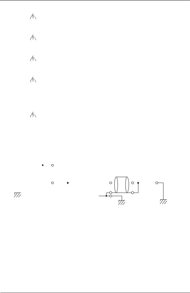
|
OMRON |
CX-Programmer – Operation Manual |
|||||||||||||||||||
|
Caution |
Confirm safety at the destination node before transferring a program to |
|||||||||||||||||||
|
another node or changing contents of the I/O memory area. Doing either of |
||||||||||||||||||||
|
these without confirming safety may result in injury. |
||||||||||||||||||||
|
Caution |
Execute online edit only after confirming that no adverse effects will be |
|||||||||||||||||||
|
caused by extending the cycle time. Otherwise, the input signals may not |
||||||||||||||||||||
|
be readable. |
||||||||||||||||||||
|
Caution |
If synchronous unit operation is being used, perform online editing only |
|||||||||||||||||||
|
after confirming that an increased synchronous processing time will not |
||||||||||||||||||||
|
affect the operation of the main and slave axes. |
||||||||||||||||||||
|
Caution |
Confirm safety sufficiently before monitoring power flow and present value |
|||||||||||||||||||
|
status in the Ladder Section window or when monitoring present values in |
||||||||||||||||||||
|
the Watch window. If force-set/reset or set/reset operations are |
||||||||||||||||||||
|
inadvertently performed by pressing short-cut keys, the devices connected |
||||||||||||||||||||
|
to Output Units may malfunction, regardless of the operating mode of the |
||||||||||||||||||||
|
CPU Unit. |
||||||||||||||||||||
|
Caution |
Caution is required when connecting peripheral devices, such as a |
|||||||||||||||||||
|
personal computer, to the PLC when Units with non-isolated power |
||||||||||||||||||||
|
supplies, such as the CS1W-CLK12/CLK52(-V1), that are connected to an |
||||||||||||||||||||
|
external power supply are mounted to the PLC. If the 24-V side is grounded |
||||||||||||||||||||
|
on the external power supply, a short will be created if the 0-V side of the |
||||||||||||||||||||
|
peripheral device is grounded. When connecting peripheral devices, either |
||||||||||||||||||||
|
ground the 0-V side of the external power supply or do not ground the |
||||||||||||||||||||
|
external power supply at all. |
||||||||||||||||||||
|
Non-isolated |
||||||||||||||||||||
|
24-VDC |
power supplies |
|||||||||||||||||||
|
External power |
Cable |
|||||||||||||||||||
|
supply |
||||||||||||||||||||
|
0-VDC |
0-VDC |
0-VDC |
||||||||||||||||||
|
FG |
||||||||||||||||||||
|
FG |
FG |
FG |
||||||||||||||||||
|
Controller Link unit |
CPU unit |
Peripheral devices |
||||||||||||||||||
CX-Programmer_Page (ix)

|
OMRON |
CX-Programmer – Operation Manual |
|
Application Precaution
Observe the following precautions when using the CX-Programmer.
•Observe the following precautions before starting the CX-Programmer.
•Exit all applications not directly related to the CX-Programmer. Particularly exit any software such as screen savers, virus checkers, email or other communications software, and schedulers or other applications that start up periodically or automatically.
•Disable sharing hard disks, printers, or other devices with other computers on any network.
•With some notebook computers, the RS-232C port is allocated to a modem or an infrared port by default. Follow the instructions in documentation for your computer and enable using the RS-232C port as a normal serial port.
•With some notebook computers, the default settings for saving energy do not supply the rated power to the RS-232C port. There may be both Windows settings for saving energy, as well as setting for specific computer utilities and BIOS. Following the instructions in documentation for your computer, disable all energy saving settings.
•Do not turn OFF the power supply to the PLC or disconnect the connecting cable while the CX-Programmer is online with the PLC. The computer may malfunction.
•With the CS/CJ-series PLCs, when creating an AUTOEXEC.IOM file from the CX-Programmer to automatically transfer data at startup, set the first write address to D20000 and be sure that the size of data written does not exceed the size of the DM Area. When the data file is read from the Memory Card at startup, data will be written in the CPU Unit starting at D20000 even if another address was set when the AUTOEXEC.IOM file was created. Also, if the DM Area is exceeded (which is possible when the CX-Programmer is used), the remaining data will be written to the EM Area. Refer to information on file operations in the CS/CJ-series Programming Manual for details.
•Confirm that no adverse effect will occur in the system before attempting
any of the following. Not doing so may result in an unexpected operation. Changing the operating mode of the PLC.
•Force-setting/force-resetting any bit in memory.
•Changing the present value of any word or any set value in memory.
•Check the user program for proper execution before actually running it on the Unit. Not checking the program may result in an unexpected operation.
•Precaution on Using Indirect DM and EM Addresses in Comparison Instructions:
When indirect DM or EM addresses are used as operands in comparison instructions, the top portion of the comparison instruction will be displayed in yellow when it is being monitored. At that time the power flow will not be monitored to the right of such comparison instructions. The contact and coil status, and present values of operands in special instructions will be displayed normally.
CX-Programmer_Page (x)

|
OMRON |
CX-Programmer – Operation Manual |
|
•The user program and parameter area data in CS1-H CPU Units is backed up in the built-in flash memory. The BKUP indicator will light on the front of the CPU Unit when the backup operation is in progress. Do not turn OFF the power supply to the CPU Unit when the BKUP indicator is lit. The data will not be backed up if power is turned OFF.
To display the status of writing to flash memory on the CX-Programmer, place a checkmark by Display dialog to show PLC Memory Backup Status on the PLC properties and then select Windows | PLC Memory Backup Status from the Windows menu.
•Precaution in Changing the PLC Type
On the CX-Programmer, you can change the PLC (device) type or CPU type. When these are changed, however, only the data for the ladder program and the symbol tables are changed. The following data will be initialized and must be reset.
•PLC Setup
•Expansion instructions
•I/O tables
•PLC memory
Particularly the PLC Setup has a large impact on PLC system operation. Be careful to reset all require settings after changing the PLC type.
If expansion instruction allocations are not reset, program errors could occur, preventing the PLC from running. Always restore the expansion instruction allocates to the previous settings after changing the PLC type.
CX-Programmer_Page (xi)

|
OMRON |
CX-Programmer – Operation Manual |
|
Observe the following precautions when using the CX-Net.
•Do not change the operating mode of the CPU Unit without first confirming that operation of the controlled system will not be affect.
•Do not run the user program on the PLC until its operation has been checked sufficiently.
•The data link mode (manual setting or automatic setting) and data link method are determined according to the data link setting in the startup node. In the startup node, set a data link table in the case of manual setting and data link automatic setting parameters in the case of automatic setting. If the settings are incorrect, the data link will not start.
•Check the following items before starting data links. If incorrect data link tables or parameters are set, injury may result due to unexpected operation of the system. Even if the correct data link tables and parameters have been set, do not start or stop data links before verifying that there will be no adverse influence on the system.
(1)Manually Set Data Links
Check the data link tables in each node participating in the data link to see that they are correct.
Be sure that data link tables are deleted from nodes that are not participating in the data links.
(2) Automatically Set Data Links
Be sure that the correct DM parameters have been set in the data link startup node.
•CPU Bus Units will be automatically restarted when routing tables are transferred from a Programming Device to the CPU Unit. Resetting is required to use the new tables. Confirm that restarting the CPU Bus Units will not adversely affect system operation before transferring routing tables.
•When Special I/O Unit or CPU Unit settings are performed in the I/O Table Window and then transferred from the PLC Memory Window, the following warning will be displayed if the allocated DM Area/CIO Area addresses set for Special I/O Units or CPU Bus Units in the I/O Table Window on the computer overlap with the PLC data table addresses. Unless the CPU Bus Unit or Special I/O Unit settings have been previously transferred to the CPU Unit and the allocated DM Area/CIO Area data in the PLC data table for Special I/O Units or CPU Bus Units is to be overwritten, always click the No Button, shift the address, and repeat the transfer procedure.
•CPU Bus Unit and Special I/O Unit settings are not checked for logical consistency. Be very careful of the logical consisting of the overall settings when making any setting that affects other settings, e.g., settings that enable or disable other settings. Transfer the Special I/O Unit or CPU Bus Unit settings to the PLC and then start operation, being aware that any logical inconsistencies may produce unexpected operation.
•For example, if one setting selects either user settings or default settings and is set to use the default settings, it will not automatically change to enable user settings even if the related user settings are made. To use the user settings, they will have to be enabled manually and specifically in the setting that selects either user settings or default settings.
CX-Programmer_Page (xii)
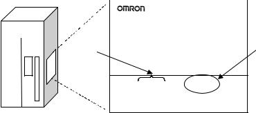
Unit Versions of CS/CJ/CP-series CPU Units
Unit Versions
A “unit version” has been introduced to manage CPU Units in the CS/CJ/CP
Series according to differences in functionality accompanying Unit upgrades.
This applies to the CJ2, CS1-H, CJ1-H, CJ1M, CS1D, CP1H, CP1L, and
CP1E CPU Units.
Notation of Unit Versions on Products
The unit version is given to the right of the lot number on the nameplate of the products for which unit versions are being managed, as shown below.
|
CS/CJ/CP-series CPU Unit |
Produce nameplate |
|||||
|
CS1H-CPU67H |
||||||
|
CPU UNIT |
||||||
|
Lot No. |
Unit version |
|||||
Example for unit version 3.0
|
Lot No. 040715 0000 |
Ver.3.0 |
|
|
OMRON Corporation |
MADE IN JAPAN |
|
•CS1-H, CJ1-H, and CJ1M CPU Units (except for low-end models) manufactured on or before November 4, 2003 do not have a unit version given on the CPU Unit (i.e., the location for the unit version shown above is blank).
•The unit version of the CJ1-H-R CPU Units begins at version 4.0.
•The unit version of the CS1-H, CJ1-H, and CJ1M CPU Units, as well as the CS1D CPU Units for Single-CPU Systems, begins at version 2.0.
•The unit version of the CS1D CPU Units for Duplex-CPU Systems begins at version 1.1.
•The unit version of the CP1H/CP1L/CP1E CPU Units begins at version 1.0, except for the CP1H-Y@@@@-@, for which the unit version begins at version 1.1.
•CPU Units for which a unit version is not given are called Pre-Ver. @.@
CPU Units, such as Pre-Ver. 2.0 CPU Units and Pre-Ver. 1.1 CPU Units.
Confirming Unit Versions with Support Software
CX-Programmer version 4.0 can be used to confirm the unit version using one of the following two methods.
•Using the PLC Information
•Using the Unit Manufacturing Information (This method can be used for Special I/O Units and CPU Bus Units as well.)
Note CX-Programmer version 3.3 or lower cannot be used to confirm unit versions.
PLC Information
•If you know the device type and CPU type, select them in the Change PLC Dialog Box, go online, and select PLC — Edit — Information from the menus.
•If you don’t know the device type and CPU type, but are connected directly to the CPU Unit on a serial line, select PLC — Auto Online to go online, and then select PLC — Edit — Information from the menus.
In either case, the following PLC Information Dialog Box will be displayed.
CX-Programmer_Page (xiii)
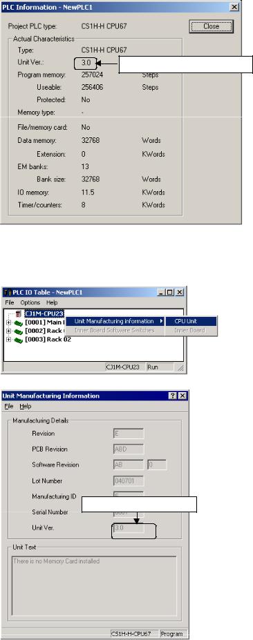
Unit version
Use the above display to confirm the unit version of the CPU Unit.
Unit Manufacturing Information
In the IO Table Window, right-click and select Unit Manufacturing information — CPU Unit.
The following Unit Manufacturing information Dialog Box will be displayed
Unit version
Use the above display to confirm the unit version of the CPU Unit connected online.
CX-Programmer_Page (xiv)
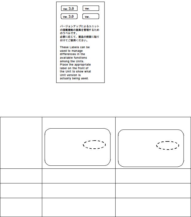
Using the Unit Version Labels
The following unit version labels are provided with the CPU Unit.
These labels can be attached to the front of previous CPU Units to differentiate between CPU Units of different unit versions.
Unit Version Notation
In this manual, the unit version of a CPU Unit is given as shown in the following table.
|
Product nameplate CPU Units on which no unit version is |
Units on which a version is given |
|
given |
(Ver. @.@) |
|
Lot No. XXXXXX XXXX |
Lot No. XXXXXX XXXX |
Ver.@.@ |
|
OMRON Corporation |
MADE IN JAPAN |
Meaning
Designating individual
CPU Units (e.g., the Pre-Ver. 2.0 CS1-H CPU Units CS1H-CPU67H CPU Unit Ver. @.@ CS1H-CPU67H)
Designating groups of
CPU Units (e.g., the Pre-Ver. 2.0 CS1-H CPU Units CS1-H CPU Units Ver. @.@ CS1-H CPU Units)
Designating an entire
series of CPU Units
Pre-Ver. 2.0 CS-series CPU Units CS-series CPU Units Ver. @.@
(e.g., the CS-series CPU Units)
CX-Programmer_Page (xv)

Unit Versions and Lot Numbers
CX-Programmer_Page (xvi)
Function Support by Unit Version
CS1-H CPU Units (CS1@-CPU@@H)
|
Function |
Unit version |
|||
|
Pre-Ver. 2.0 CPU |
CPU Units Ver. 2.0 or |
|||
|
Units |
later |
|||
|
Downloading and Uploading Individual Tasks |
— |
OK |
||
|
Improved Read Protection Using Passwords |
— |
OK |
||
|
Write Protection from FINS Commands Sent to CPU Units via |
— |
OK |
||
|
Networks |
||||
|
Online Network Connections without I/O Tables |
— |
OK |
||
|
Communications through a Maximum of 8 Network Levels |
— |
OK |
||
|
Connecting Online to PLCs via NS-series PTs |
OK from lot number |
OK |
||
|
030201 |
||||
|
Setting First Slot Words |
OK for up to 8 groups |
OK for up to 64 groups |
||
|
Automatic Transfers at Power ON without a Parameter File |
— |
OK |
||
|
Automatic Detection of I/O Allocation Method for Automatic |
— |
— |
||
|
Transfer at Power ON |
||||
|
Operation Start/End Times |
— |
OK |
||
|
New |
MILH, MILR, MILC |
— |
OK |
|
|
Application |
=DT, <>DT, <DT, <=DT, >DT, >=DT |
— |
OK |
|
|
Instructions |
||||
|
BCMP2 |
— |
OK |
||
|
GRY |
OK from lot number |
OK |
||
|
030201 |
||||
|
TPO |
— |
OK |
||
|
DSW, TKY, HKY, MTR, 7SEG |
— |
OK |
||
|
EXPLT, EGATR, ESATR, ECHRD, ECHWR |
— |
OK |
||
|
Reading/Writing CPU Bus Units with IORD/IOWR |
OK from lot number |
OK |
||
|
030418 |
||||
|
PRV2 |
— |
— |
CX-Programmer_Page (xvii)
CS1D CPU Units
|
Function |
CS1D CPU Units for Duplex-CPU |
CS1D CPU Units |
|||
|
Systems (CS1D-CPU@@H) |
for Single-CPU |
||||
|
Systems |
|||||
|
(CS1D-CPU@@S) |
|||||
|
Pre-Ver. 1.1 CPU |
CPU Unit Ver. 1.1 |
CPU Unit Ver. 2.0 |
|||
|
Units |
or later |
||||
|
Functions |
Duplex CPU Units |
OK |
OK |
— |
|
|
unique to |
Online Unit Replacement |
OK |
OK |
OK |
|
|
CS1D CPU |
|||||
|
Units |
Duplex Power Supply Units |
OK |
OK |
OK |
|
|
Duplex Controller Link Units |
OK |
OK |
OK |
||
|
Duplex Ethernet Units |
— |
OK |
OK |
||
|
Downloading and Uploading Individual Tasks |
— |
— |
OK |
||
|
Improved Read Protection Using Passwords |
— |
— |
OK |
||
|
Write Protection from FINS Commands Sent |
— |
— |
OK |
||
|
to CPU Units via Networks |
|||||
|
Online Network Connections without I/O |
— |
— |
OK |
||
|
Tables |
|||||
|
Communications through a Maximum of 8 |
— |
— |
OK |
||
|
Network Levels |
|||||
|
Connecting Online to PLCs via NS-series |
— |
— |
OK |
||
|
PTs |
|||||
|
Setting First Slot Words |
— |
— |
OK for up to 64 |
||
|
groups |
|||||
|
Automatic Transfers at Power ON without a |
— |
— |
OK |
||
|
Parameter File |
|||||
|
Automatic Detection of I/O Allocation Method |
— |
— |
— |
||
|
for Automatic Transfer at Power ON |
|||||
|
Operation Start/End Times |
— |
OK |
OK |
||
|
New |
MILH, MILR, MILC |
— |
— |
OK |
|
|
Application |
=DT, <>DT, <DT, <=DT, >DT, |
— |
— |
OK |
|
|
Instructions |
|||||
|
>=DT |
|||||
|
BCMP2 |
— |
— |
OK |
||
|
GRY |
— |
— |
OK |
||
|
TPO |
— |
— |
OK |
||
|
DSW, TKY, HKY, MTR, 7SEG |
— |
— |
OK |
||
|
EXPLT, EGATR, ESATR, |
— |
— |
OK |
||
|
ECHRD, ECHWR |
|||||
|
Reading/Writing CPU Bus |
— |
— |
OK |
||
|
Units with IORD/IOWR |
|||||
|
PRV2 |
— |
— |
— |
CX-Programmer_Page (xviii)
CJ1-H/CJ1M CPU Units
|
Function |
CJ1-H CPU Units |
CJ1M CPU Units |
|||||
|
(CJ1H-CPU@@H-R) |
CJ1M-CPU12/13/22/23 |
CJ1M- |
|||||
|
(CJ1@-CPU@@H) |
CPU11/21 |
||||||
|
(CJ1G-CPU@@P) |
|||||||
|
Pre-Ver. 2.0 |
CPU Units |
Pre-Ver. 2.0 |
CPU Units |
CPU Units |
|||
|
CPU Units |
Ver. 2.0 |
CPU Units |
Ver. 2.0 |
Ver. 2.0 or |
|||
|
later |
|||||||
|
Downloading and Uploading |
— |
OK |
— |
OK |
OK |
||
|
Individual Tasks |
|||||||
|
Improved Read Protection |
— |
OK |
— |
OK |
OK |
||
|
Using Passwords |
|||||||
|
Write Protection from FINS |
— |
OK |
— |
OK |
OK |
||
|
Commands Sent to CPU Units |
|||||||
|
via Networks |
|||||||
|
Online Network Connections |
OK, but only if |
OK |
OK, but only if |
OK |
OK |
||
|
without I/O Tables |
I/O table |
I/O table |
|||||
|
allocation at |
allocation at |
||||||
|
power ON is set |
power ON is set |
||||||
|
Communications through a |
OK for up to 8 |
OK for up to 64 |
OK for up to 8 |
OK for up to 64 |
OK for up to 64 |
||
|
Maximum of 8 Network Levels |
groups |
groups |
groups |
groups |
groups |
||
|
Connecting Online to PLCs via |
OK from lot |
OK |
OK from lot |
OK |
OK |
||
|
NS-series PTs |
number 030201 |
number 030201 |
|||||
|
Setting First Slot Words |
— |
OK |
— |
OK |
OK |
||
|
Automatic Transfers at Power |
— |
OK |
— |
OK |
OK |
||
|
ON without a Parameter File |
|||||||
|
Automatic Detection of I/O |
— |
OK |
— |
OK |
OK |
||
|
Allocation Method for |
|||||||
|
Automatic Transfer at Power |
|||||||
|
ON |
|||||||
|
Operation Start/End Times |
— |
OK |
— |
OK |
OK |
||
|
New |
MILH, MILR, |
— |
OK |
— |
OK |
OK |
|
|
Application |
MILC |
||||||
|
Instructions |
=DT, <>DT, <DT, |
— |
OK |
— |
OK |
OK |
|
|
<=DT, >DT, |
|||||||
|
>=DT |
|||||||
|
BCMP2 |
— |
OK |
OK |
OK |
OK |
||
|
GRY |
OK from lot |
OK |
OK from lot |
OK |
OK |
||
|
number 030201 |
number 030201 |
||||||
|
TPO |
— |
OK |
— |
OK |
OK |
||
|
DSW, TKY, HKY, |
— |
OK |
— |
OK |
OK |
||
|
MTR, 7SEG |
|||||||
|
EXPLT, EGATR, |
— |
OK |
— |
OK |
OK |
||
|
ESATR, ECHRD, |
|||||||
|
ECHWR |
|||||||
|
Reading/Writing |
— |
OK |
— |
OK |
OK |
||
|
CPU Bus Units |
|||||||
|
with IORD/IOWR |
|||||||
|
PRV2 |
— |
— |
— |
OK, but only for |
OK, but only for |
||
|
models with |
models with |
||||||
|
built-in I/O |
built-in I/O |
CX-Programmer_Page (xix)
Functions Supported by Unit Version 3.0 or Later
CS1-H CPU Units (CS1@-CPU@@H)
|
Function |
Unit version |
||||
|
Pre-Ver. 2.0, Ver. |
Ver. 3.0 |
Ver. 4.0 |
|||
|
2.0 |
(See note.) |
||||
|
Function blocks (supported for CX-Programmer Ver. |
— |
OK |
OK |
||
|
5.0 or higher) |
|||||
|
Serial Gateway (converting FINS commands to |
— |
OK |
OK |
||
|
CompoWay/F commands at the built-in serial port) |
|||||
|
Comment memory (in internal flash memory) |
— |
OK |
OK |
||
|
Expanded simple backup data |
— |
OK |
OK |
||
|
New |
TXDU(256), RXDU(255) (support |
— |
OK |
OK |
|
|
application |
no-protocol communications with |
||||
|
instructions |
Serial Communications Units with |
||||
|
unit version 1.2 or later) |
|||||
|
Model conversion instructions: |
— |
OK |
OK |
||
|
XFERC(565), DISTC(566), |
|||||
|
COLLC(567), MOVBC(568), |
|||||
|
BCNTC(621) |
|||||
|
Special function block instructions: |
— |
OK |
OK |
||
|
GETID(286) |
|||||
|
Additional |
TXD(235) and RXD(236) |
— |
OK |
OK |
|
|
instruction |
instructions (support no-protocol |
||||
|
functions |
communications with Serial |
||||
|
Communications Boards with unit |
|||||
|
version 1.2 or later) |
|||||
|
New |
ASCII conversion instructions |
— |
— |
OK |
|
|
application |
(NUMBER-TO-ASCII and ASCII- |
||||
|
instructions |
TONUMBER) |
||||
|
Text File Write (TWRIT) |
|||||
|
Improved |
Online editing of function blocks |
— |
— |
OK |
|
|
function block |
|||||
|
Input-output variables are |
— |
— |
OK |
||
|
(FB) functions |
|||||
|
supported. |
|||||
|
(Input-output variables can be |
|||||
|
specified in arrays.) |
|||||
|
The STRING data type and text- |
— |
— |
OK |
||
|
string processing functions are |
|||||
|
supported in ST language. |
|||||
|
Using ST language programming in tasks |
— |
— |
OK with CX- |
||
|
Programmer Ver. 7.2 |
|||||
|
or higher |
|||||
|
Using SFC programming in tasks |
— |
— |
OK with CX- |
||
|
Programmer Ver. 7.2 |
|||||
|
or higher |
|||||
Note: CX-Programmer version 7.0 or higher is required to use functions added for unit version 4.0. Additional functions are supported if CX-Programmer version 7.2 or higher is used.
CS1D CPU Units
Unit version 3.0 (Ver. 3.0) is not supported.
CX-Programmer_Page (xx)
CJ1-H/CJ1M CPU Units (CJ1@-CPU@@H, CJ1M-CPU@@)
|
Function |
Unit version |
||||
|
Pre-Ver. 2.0, |
Ver. 3.0 |
Ver. 4.0 |
|||
|
Ver. 2.0 |
(See note.) |
||||
|
Function blocks (supported for CX-Programmer Ver. |
— |
OK |
OK |
||
|
5.0 or higher) |
|||||
|
Serial Gateway (converting FINS commands to |
— |
OK |
OK |
||
|
CompoWay/F commands at the built-in serial port) |
|||||
|
Comment memory (in internal flash memory) |
— |
OK |
OK |
||
|
Expanded simple backup data |
— |
OK |
OK |
||
|
Additional |
PRV(881) and PRV2(883) |
— |
OK |
OK |
|
|
instruction |
instructions: Added high-frequency |
||||
|
functions |
calculation methods for calculating |
||||
|
pulse frequency. (CJ1M CPU Units |
|||||
|
only) |
|||||
|
New |
TXDU(256), RXDU(255) (support |
— |
OK |
OK |
|
|
application |
no-protocol communications with |
||||
|
instructions |
Serial Communications Units with |
||||
|
unit version 1.2 or later) |
|||||
|
Model conversion instructions: |
— |
OK |
OK |
||
|
XFERC(565), DISTC(566), |
|||||
|
COLLC(567), MOVBC(568), |
|||||
|
BCNTC(621) |
|||||
|
Special function block instructions: |
— |
OK |
OK |
||
|
GETID(286) |
|||||
|
Additional |
TXD(235) and RXD(236) |
— |
OK |
OK |
|
|
instruction |
instructions (support no-protocol |
||||
|
functions |
communications with Serial |
||||
|
Communications Boards with unit |
|||||
|
version 1.2 or later) |
|||||
|
New |
ASCII conversion instructions |
— |
— |
OK |
|
|
application |
(NUMBER-To-ASCII and ASCII- |
||||
|
instructions |
TO NUMBER) |
||||
|
Improved |
Online editing of function blocks |
— |
— |
OK |
|
|
function block |
|||||
|
Input-output variables are |
— |
— |
OK |
||
|
(FB) functions |
|||||
|
supported. (Input-output variables |
|||||
|
can be specified in arrays.) |
|||||
|
The STRING data type and text- |
— |
— |
OK |
||
|
string processing functions are |
|||||
|
supported in ST language. |
|||||
|
Using ST language programming in tasks |
— |
— |
OK with CX- |
||
|
Programmer Ver. 7.2 |
|||||
|
or higher |
|||||
|
Using SFC programming in tasks |
— |
— |
OK with CX- |
||
|
Programmer Ver. 7.2 |
|||||
|
or higher |
|||||
Note: CX-Programmer version 7.0 or higher is required to use functions added for unit version 4.0. Additional functions are supported if CX-Programmer version 7.2 or higher is used.
CX-Programmer_Page (xxi)
Functions Supported by Unit Version for CJ2 CPU Units (CJ2H-CPU6@-EIP, CJ2HCPU6@)
Unit Version 1.2 or Later
CX-Programmer version 8.3 or higher must be used to enable using the functions added for unit version 1.2.
|
Unit |
CJ2H CPU Unit |
|
Model |
CJ2H-CPU6@-EIP |
|
CJ2H-CPU6@ |
|
|
Unit version |
Unit version 1.2 |
|
Item |
|
|
EM Area force-setting/resetting |
Supported. |
Unit Version 1.1 or Later
CX-Programmer version 8.1 or higher must be used to enable using the functions added for unit version 1.1.
|
Unit |
CJ2H CPU Unit |
|
|
Model |
CJ2H-CPU6@-EIP |
|
|
CJ2H-CPU6@ |
||
|
Unit version |
Unit version 1.1 |
Unit version 1.0 |
|
Item |
||
|
High-speed interrupt function |
Supported. |
Not supported. |
|
Decreased overhead time for interrupt tasks |
||
|
Minimum interval setting of 0.1 ms for Scheduled |
||
|
Interrupt Task |
||
|
Changing the minimum cycle time setting in |
Supported. |
Not supported. |
|
MONITOR mode |
||
|
Synchronous unit operation |
Supported. |
Not supported. |
Unit Version 1.0
All functions that are supported by unit version 4.0 or later of the CJ1 CPU Units are supported by unit version 1.0 of the CJ2 CPU Units.
CX-Programmer version 8.0 or higher must be used to enable using unit version 1.0 of the CJ2 CPU Units.
CX-Programmer_Page (xxii)

Functions Supported by Unit Version for CP-series CPU Units
Functions Supported by Unit Version 1.0 and 1.1
Functionality is the same as that for CS/CJ-series CPU Units with unit version 3.0. The functionality added for CS/CJ-series CPU Unit unit version 4.0 is not supported.
CP1H CPU Units
•CX-Programmer version 6.11 or higher is required to use CP1H-X@@@@- @/XA@@@@-@ with unit version 1.1 or 1.0.
•CX-Programmer version 6.20 or higher is required to use CP1H-Y@@@@- @ with unit version 1.1.
|
CPU Unit |
CP1H CPU Unit |
||||
|
Model |
CP1H-@@@@-@ |
CP1H-Y@@@@-@ |
|||
|
CP1H-XA@@@@-@ |
(See note 2.) |
||||
|
(See note 1.) |
|||||
|
Unit version |
Ver. 1.1 or |
Ver. 1.0 |
Ver. 1.1 |
||
|
Function |
later |
||||
|
Pulse |
Allocated built-in |
4 axes at |
2 axes at |
2 axes 100 kHz |
|
|
outputs |
I/O terminals |
100 kHz |
100 kHz |
||
|
2 axes at |
|||||
|
30 kHz |
|||||
|
Special pulse |
None |
2 axes at 1 kHz |
|||
|
output terminals |
|||||
Note 1. The unit version for the CP1H-X@@@@-@/XA@@@@-@ begins at 1.0.
2.The unit version for the CP1H-X@@@@-@ begins at 1.1.
3.CX-Programmer version 7.11 or higher is required to use CP1L CPU Units with unit version 1.0.
CX-Programmer_Page (xxiii)
Unit Versions and Programming Devices
CX-Programmer version 4.0 or higher must be used to enable using the functions added for CPU Unit Ver. 2.0. The following tables show the relationship between unit versions and CX-Programmer versions.
Unit Versions and Programming Devices for CJ2 CPU Units
|
CPU Unit |
Functions |
Required Programming Device |
||||
|
CX-Programmer |
||||||
|
Ver. 7.1 or lower |
Ver. 8.0 |
Ver. 8.1 |
Ver. 8.2 |
Ver. 8.3 |
||
|
CJ2H-CPU6@-EIP |
Functions for unit version |
× |
||||
|
Unit version 1.0 |
1.0 |
|||||
|
CJ2H-CPU6@-EIP |
Functions added for unit |
× |
∆ |
|||
|
Unit version 1.1 |
version 1.1 |
|||||
|
CJ2H-CPU6@ |
Functions added for unit |
× |
∆ |
|||
|
Unit version 1.1 |
version 1.1 |
|||||
|
CJ2H-CPU6@-EIP |
Functions added for unit |
× |
∆ |
∆ |
∆ |
|
|
Unit version 1.2 |
version 1.2 |
|||||
|
CJ2H-CPU6@ |
Functions added for unit |
× |
∆ |
∆ |
∆ |
|
|
Unit version 1.2 |
version 1.2 |
|||||
×: Cannot be used, ∆: Can be used except for new functions added for unit versions, : Can be used
Note 1. It is not necessary to upgrade the version of the CX-Programmer if functionality that was enhanced for the upgrade of the CPU Unit will not be used.
2.CX-Programmer version 8.1 or higher is required to use the functions added for unit version 1.1. The high-speed interrupt function and changing the minimum cycle time setting in MONITOR mode, however, are also supported by CX-Programmer version 8.02.
3.A Programming Console cannot be used with a CJ2H CPU Unit.
Unit Versions and Programming Devices for CPU Units Other Than CJ2 CPU Units
|
CPU Unit |
Functions |
Required Programming Device |
|||||
|
CX-Programmer |
|||||||
|
Ver. 3.3 |
Ver. 4.0 |
Ver. 5.0 |
Ver. 7.0 |
Ver. 7.2 |
Ver. 8.0 |
||
|
Ver. 6.0 |
or later |
||||||
|
CS/CJ Series CPU |
Functions added for unit |
∆ |
∆ |
∆ |
|||
|
Units, Unit Ver. 4.0 |
version 4.0 |
(See note |
|||||
|
4.) |
|||||||
|
CS/CJ Series CPU |
Functions added for unit |
∆ |
∆ |
||||
|
Units, Unit Ver. 3.0 |
version 3.0 |
||||||
|
CS/CJ Series CPU |
Functions added for unit |
∆ |
|||||
|
Units, Unit Ver. 2.0 |
version 2.0 |
||||||
|
CS1D CPU Units for |
Functions added for unit |
∆ |
|||||
|
Single-CPU Systems, |
version 2.0 |
||||||
|
Unit Ver. 2.0 |
|||||||
|
CS1D CPU Units for |
Functions added for unit |
∆ |
|||||
|
Duplex-CPU Systems, |
version 1.1 |
||||||
|
Unit Ver.1.1 |
|||||||
×: Cannot be used, ∆: Can be used except for new functions added for unit versions, : Can be used
Note 1. As shown above, there is no need to upgrade to CX-Programmer version 4.0 as long as the functions added for unit version 2.0 or unit version 1.1 are not used.
2.CX-Programmer version 7.0 or higher is required to use functions added for unit version 4.0. Additional functions are supported if CX-Programmer version 7.2 or higher is used.
3.Unit version 4.2 of the CJ1H-CPU6@-R is supported only by CX-Programmer version 8.0 or higher.
4.CX-Programmer version 8.0 or higher is required to use unit version 4.2 of the CJ1H- CPU6@-R.
CX-Programmer_Page (xxiv)
Unit Versions of CP-series CPU Units and Programming Devices
|
CPU Unit |
Model |
Unit |
CX-Programmer version |
|||
|
version |
||||||
|
Ver. 6.11 |
Ver. 6.20 |
Ver. 7.11 |
Ver. 8.2 |
|||
|
or later |
||||||
|
CP1H CPU Units |
CP1H-X@@@@-@ |
Ver. 1.1 |
OK |
OK |
OK |
OK |
|
CP1H-XA@@@@-@ |
Ver. 1.0 |
OK |
OK |
OK |
OK |
|
|
CP1H-Y@@@@-@ |
Ver. 1.1 |
— |
OK |
OK |
OK |
|
|
CP1L CPU Units |
CP1L-M@@@@-@ |
Ver. 1.0 |
— |
— |
OK |
OK |
|
CP1L-L@@@@-@ |
||||||
|
CP1E CPU Units |
CP1E-E@@D@-A |
Ver. 1.0 |
— |
— |
— |
OK |
|
CP1E-N@@D@-@ |
||||||
Note 1. Functionality of CP1H CPU Units with unit version 1.0 or 1.0 and CP1L CPU Units with unit version 1.0 is the same as that for CS/CJ-series CPU Units with unit version 3.0. The functionality added for CS/CJ-series CPU Unit unit version 4.0 is not supported.
2.There is no need to upgrade to CX-Programmer as long as the upgraded functionality is not used.
Device Type Setting
The unit version does not affect the setting made for the device type on the CX-Programmer. Select the device type as shown in the following table regardless of the unit version of the CPU Unit.
|
Series |
CPU Unit group |
CPU Unit model |
Device type setting on |
|
CX-Programmer |
|||
|
CS Series |
CS1-H CPU Units |
CS1G-CPU@@H |
CS1G-H |
|
CS1H-CPU@@H |
CS1H-H |
||
|
CS1D CPU Units for Duplex-CPU Systems |
CS1D-CPU@@H |
CS1D-H (or CS1H-H) |
|
|
CS1D CPU Units for Single-CPU Systems |
CS1D-CPU@@S |
CS1D-S |
|
|
CJ Series |
CJ2 CPU Units |
CJ2H-CPU6@(-EIP) |
CJ2H |
|
CJ1-H CPU Units |
CJ1G-CPU@@H |
CJ1G-H |
|
|
CJ1GCPU@@P |
|||
|
CJ1H-CPU@@H–R |
|||
|
CJ1H-CPU@@H |
|||
|
CJ1M CPU Units |
CJ1M-CPU@@ |
CJ1M |
|
|
CP Series |
CP1H CPU Units |
CP1H-X@@@@-@ |
CP1H |
|
CP1H-XA@@@@-@ |
|||
|
CP1H-Y@@@@-@ |
|||
|
CP1L CPU Units |
CP1L-M@@@@-@ |
CP1L |
|
|
CP1L-L@@@@-@ |
|||
|
CP1E CPU Units |
CP1E-E@@D@-A |
CP1E |
|
|
CP1E-N@@D@-@ |
Note Device types not supported by the CX-Programmer version that is being used will not be displayed on the pull-down list of the Device type Field.
CX-Programmer_Page (xxv)
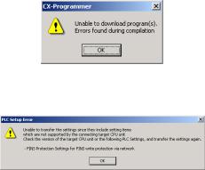
Troubleshooting Problems with Unit Versions on the CX-Programmer
|
Problem |
Cause |
Solution |
|
An attempt was made using CX- |
Check the program or change |
|
|
Programmer version 4.0 or |
the CPU Unit being |
|
|
higher to download a program |
downloaded to a CPU Unit |
|
|
containing instructions supported |
Ver. 2.0 or later. |
|
|
only by CPU Units Ver. 2.0 or |
||
|
After the above message is displayed, a compiling |
later to a Pre-Ver. 2.0 CPU Units. |
|
|
error will be displayed on the Compile Tab Page in |
||
|
the Output Window. |
||
|
An attempt was made using CX- |
Check the settings in the PLC |
|
|
Programmer version 4.0 or |
Setup or change the CPU Unit |
|
|
higher to download a PLC Setup |
being downloaded to a CPU |
|
|
containing settings supported |
Unit Ver. 2.0 or later. |
|
|
only by CPU Units Ver. 2.0 or |
||
|
later (i.e., not set to their default |
||
|
values) to a Pre-Ver. 2.0 CPU |
||
|
Units. |
||
|
«????» is displayed in a program transferred from the |
CX-Programmer version 3.3 or |
The new instructions cannot |
|
PLC to the CX-Programmer. |
lower was used to upload a |
be uploaded using CX- |
|
program containing instructions |
Programmer version 3.3 or |
|
|
supported only by CPU Units |
lower. Use CX-Programmer |
|
|
Ver. 2.0 or later from a CPU Unit |
version 4.0 or higher. |
|
|
Ver. 2.0 or later. |
CX-Programmer_Page (xxvi)

|
OMRON |
PART 1: CX-Programmer |
|
Notice
OMRON products are manufactured for use according to proper procedures by a qualified operator and only for the purposes described in this manual.
The following conventions are used to indicate and classify precautions in this manual. Always heed the information provided in them. Failure to heed precautions can result in injury to people or damage to the product.
DANGER Indicates an imminently hazardous situation which, if not avoided, will result in death or serious injury. Additionally, there may be severe property damage.
WARNING Indicates a potentially hazardous situation which, if not avoided, could result in death or serious injury. Additionally, there may be severe property damage.
Caution Indicates a potentially hazardous situation which, if not avoided, may result in minor or moderate injury, or property damage.
OMRON Product References
All OMRON products are capitalized in this manual. The word “Unit” is also capitalized when it refers to an OMRON product, regardless of whether or not it appears in the proper name of the product.
The abbreviation “PLC” means Programmable Logic Controller and is not used as an abbreviation for anything else.
CX-Programmer_Page (i)

|
OMRON |
PART 1: CX-Programmer |
|
Visual Aids
The following headings appear in the left column of the manual to help you locate different types of information.
Indicates information of particular interest for efficient and convenient operation of the product.
1, 2, 3… Indicates lists of one sort or another, such as procedures, checklists etc.
Represents a shortcut on the Toolbar to one of the options available on the menu of the same window.
OMRON, 2005
All rights reserved. No part of this publication may be reproduced, stored in a retrieval system, or transmitted, in any form, or by any means, mechanical, electronic, photocopying, recording, or otherwise, without the prior written permission of OMRON.
All copyright and trademarks acknowledged.
No patent liability is assumed with respect to the use of the information contained herein. Moreover, because OMRON is constantly striving to improve its high-quality products, the information contained in this manual is subject to change without notice. Every precaution has been taken in the preparation of this manual. Nevertheless, OMRON assumes no responsibility for errors or omissions. Neither is any liability assumed for damages resulting from the use of the information contained in this publication.
CX-Programmer_Page (ii)

|
OMRON |
PART 1: CX-Programmer |
|
About this Part
This part describes the CX-Programmer application and its ability to create and maintain programs for use with OMRON SYSMAC CS/CJ/CP, CV and C PLCs. It does not provide detailed information concerning the PLCs themselves, for this information the commercial manual for the device must be consulted.
This part contains the following chapters:
•Precautions. This portion describes general precautions for using the CX-Programmer (including CX-Server PLC Tools).
•Version Upgrade Information. This portion describes the changes that have been made from version 3.0 to version 3.1 of the CX-Programmer.
•Chapter 1 Technical Specifications. This chapter describes the CX-Programmer software in general terms and also provides details of the operating environment and minimum configuration necessary for the satisfactory operation of CX-Programmer.
•Chapter 2 Quick Start Guide. This chapter describes the basic features of CX-Programmer together with a simple tutorial for familiarization purposes.
•Chapter 3 Project Reference. This describes the features common to two or more parts of CXProgrammer.
•Chapter 4 Reference. This chapter introduces the features contained in the Project workspace and discusses their associated commands and features.
•Chapter 5 Advanced Topics. This chapter discusses the more advanced topics in relation to CXProgrammer.
•Appendix A Toolbars and Keyboard Shortcuts. This appendix summarizes the toolbar and keyboard shortcuts available from CX-Programmer.
A Glossary of Terms and Index are also provided.
CX-Programmer_Page (iii)

|
OMRON |
PART 1: CX-Programmer |
|
Functions Supported by the CXProgrammer Installed from the CX-One
• Starting Specialized Support Tools from the I/O Table Window
|
Previous version |
New version (CX-Programmer Installed from CX-One) |
|
Each CPU Bus Unit or |
If the PLC model is set to the CS/CJ/CP-series, each Unit’s Programming Tool (e.g., |
|
Special I/O Unit’s |
CX-Integrator, CX-Protocol, CX-Position, or CX-Process Tool) can be started directly |
|
Programming Tool was |
from the Special I/O Unit or CPU Bus Unit in the I/O Table Window. When the |
|
started individually. |
Specialized Support Tool is started, the CX-Programmer can pass information such as |
|
the PLC model, Unit model, and online/offline status. |
Functionality Improved from Version 8.3 to 9.0
Compatible PLC Models
The CX-Programmer also supports CP1E-NA20 CPU Units (20-point CPU Units).
Supported Operating Systems
The CX-Programmer will run on Windows 7.
Data Structures Supported as Symbol Data Types
|
Previous version (version 8.3) |
New version (version 9.0) |
|
Data structures are not supported. |
CJ2 CPU Units now support data structures as |
|
symbol data types. |
Enhanced Program Input Functions
|
Previous version (version 8.3) |
New version (version 9.0) |
|
The input mode cannot be changed. |
A Smart Input Mode is supported that |
|
automatically displays suggested instructions |
|
|
and addresses. |
|
|
The input mode can be changed from a menu or |
|
|
a tool bar. |
|
|
When copying circuits to create similar rungs |
The Address Incremental Copy function can be |
|
with different addresses, the addresses must be |
used to easily create copies of similar circuit |
|
input again. |
structures with offset addresses. |
Enhanced User Interface for Menu and Option Settings
|
Previous version (version 8.3) |
New version (version 9.0) |
|
The display configuration for menus and options |
Switching to Smart Style Mode is now possible |
|
cannot be changed. |
for the menu and option setting style. |
|
Smart Style is the same type of menu and option |
|
|
setting function as the one supported in CX- |
|
|
Programmer for CP1E. |
|
|
Either the previous Classic Mode or the new |
|
|
Smart Style Mode can be selected for the menus |
|
|
and options by selecting Tools — Options and |
|
|
then setting the Menu/Options Style on the |
|
|
General Tab Page. |
Changes to Search/Replace Dialog Boxes
|
Previous version (version 8.3) |
New version (version 9.0) |
|
Searches can be performed only in the entire |
«Programs» has been added to the search range. |
|
PLC or in the data in the current view. |
|
|
The setting for the item to be searched for was |
Searched objects have been grouped into |
|
very detailed and included bit addresses, |
addresses, symbol names, and all (text strings). |
|
address, values (constants/numbers), |
|
|
mnemonics, symbols, and I/O comments. |
CX-Programmer_Page (iv)

|
OMRON |
PART 1: CX-Programmer |
|||
|
Previous version (version 8.3) |
New version (version 9.0) |
|||
|
Replacements can be performed only in the |
«Programs» has been added to the replacement |
|||
|
entire PLC or in the data in the current view. |
range. |
|||
|
Also, the selected circuits can be set as the |
||||
|
replacement range. |
||||
|
The setting for the item to be replaced was very |
Searched objects have been grouped into |
|||
|
detailed and included bit addresses, address, |
addresses, symbol names, mnemonics, and |
|||
|
values (constants/numbers), mnemonics, |
comments. |
|||
|
symbols, and I/O comments. |
Version 8.3 Upgrade Information
Functionality Improved from Version 8.2 to 8.3
Compatible PLC Models
The functionality improvements are supported for CJ2H CPU Units with unit version 1.2 or later.
TIMER and COUNTER Added as Symbol Data Types
|
Previous version (version 8.2) |
New version (version 8.3) |
|
When defining timer numbers and counter |
TIMER and COUNTER symbols are supported |
|
numbers as symbols, the following three different |
so that all of the previous three types of symbols |
|
symbols had to be registered in the symbols |
can be managed as one data type. (TIMER and |
|
table. |
COUNTER are supported only by CJ2H CPU |
|
1. Timer numbers and counter numbers |
Units with unit version 1.0 or later.) |
|
specified in instruction operands had to |
TIMER: Can be used for 1) the timer number, 2) |
|
be defined as NUMBER symbols. |
the Timer Completion Flag, and 3) the timer |
|
2. Timer and Counter Completion Flags |
present value. |
|
had to be defined as BOOL symbols. |
COUNTER: Can be used for 1) the counter |
|
3. Timer and counter present values had |
number, 2) the Counter Completion Flag, and 3) |
|
to be defined as CHANNEL symbols. |
the counter present value. |
|
Automatically assigning timer and counter |
Automatic address assignment and layout are |
|
numbers in ladder programs was not possible. |
supported for TIMER and COUNTER symbols. |
|
(TIMER and COUNTER are supported only by |
|
|
CJ2H CPU Units with unit version 1.0 or later.) |
Force-setting/resetting Bits in EM Area
|
Previous version (version 8.2) |
New version (version 8.3) |
|
Bits in the EM Area could be force-set/reset in |
With CJ2H CPU Units with unit version 1.2 or |
|
CJ2H CPU Units only for specific EM Area banks |
later, PLC • Memory Allocate • EM Memory |
|
for which automatic address assignment was |
Settings can be used to specify the EM Area |
|
used. |
banks for which bits can be force-set/reset. (The |
|
first bank is specified and force-setting/resetting |
|
|
bits is possible in that bank and all banks |
|
|
following it.) This is called the EM Area force- |
|
|
setting/resetting function. |
Searching for Symbol Names and Displaying Usage Locations from Cross-reference Popups
|
Previous version (version 8.2) |
New version (version 8.3) |
|
Searching from cross-reference pop-ups was |
Symbol names can be specified directly in cross- |
|
possible only for address specifications. (To |
reference pop-ups to display a list of locations |
|
search for symbols, you had to click the Browse |
that use the address of that symbol. |
|
button and search for symbol names from the |
|
|
Symbol Search Dialog Box.) |
CX-Programmer_Page (v)

|
OMRON |
PART 1: CX-Programmer |
|
Version 8.2 Upgrade Information
Functionality Improved from Version 8.1 to 8.2
Connecting Online to the PLC through an NV-series PT*
|
Previous version (version 8.1) |
New version (version 8.2) |
|
It was not possible to connect online from the |
It is now possible to connect online from the CX- |
|
CX-Programmer through an NV-series PT to a |
Programmer through an NV-series PT to a PLC |
|
PLC connected to the NV-series PT. |
connected to the NV-series PT. |
*Functionality improved in version 8.21 over version 8.20.
CP1E CPU Unit Supported for Connecting Online to a PLC via an NS-series PT
|
Previous version (version 8.1) |
New version (version 8.2) |
|
With a CP1E CPU Unit, it was not possible to |
With a CP1E-N@@D@-@ CPU Unit, it is now |
|
connect online from the CX-Programmer through |
possible to connect online from the CX- |
|
an NS-series PT to a PLC connected to the NS- |
Programmer through an NS-series PT to a PLC |
|
series PT. |
connected to the NS-series PT. |
Compatible PLC Models
The functionality improvements are supported for CP-series CP1E CPU Units with unit version 1.0.
Online Connection to the PLC via an NS-series PT
|
Previous version (version 8.1) |
New version (version 8.2) |
|
An online connection from the CX-Programmer |
An online connection from the CX-Programmer |
|
through an NS-series PT to a PLC connected to |
through an NS-series PT to a PLC connected to |
|
the PT was not possible. |
the PT is possible when the PLC is connected to |
|
the PT using a serial connection, Ethernet |
|
|
connection, or Controller Link connection. |
CX-Programmer_Page (vi)

|
OMRON |
PART 1: CX-Programmer |
|
Version 8.1 Upgrade Information
Functionality Improved from Version 8.0 to 8.1
Compatible PLC Models
The functionality improvements are supported for CJ-series CJ2 CPU Units (CJ2H-CPU6@(-EIP)) with unit version 1.1.
Support for Synchronous Unit Operation
Support has been added for the synchronous unit operation function for a combination of a CJ-series CJ2 CPU Unit (CJ2H-CPU6@ (-EIP)) with unit version 1.1 and CJ-series Position Control Units (CJ1W-NC@@4). Settings and monitoring are now possible for synchronous unit operation.
Improved Special I/O Unit and CPU Bus Unit Setup Functionality
Multiple dialog boxes can now be opened simultaneously when setting CJ-series Position Control Unit (CJ1W-NC@@4) parameters. In addition, the CAM Data Creation Software (WS02-MOPC2) can be used to convert cam data in a CSV file into data that can be used by a Position Control Unit, and the data can be imported to the PLC memory component of the CX-Programmer.
Improved CS/CJ Data Tracing Function
•Improved Trace Settings
With support for the synchronous unit operation function of CJ2 CPU Units with unit version 1.1, tracing can now be executed for each synchronous cycle.
•Improved Bit Graph Display
Bit graphs are displayed according to screen size, and addresses are displayed beside the graphs.
CX-Programmer_Page (vii)

|
OMRON |
PART 1: CX-Programmer |
|
Version 8.0 Upgrade Information
Functionality Improved from Version 7.2 to 8.0
Support has been added for the following PLC models as part of the version 7.2 to version 7.3
upgrade.
Compatible PLC Models
New CP-series CP1L CPU Units
The CP-series CP1L CPU Units (CP1L-L10D@-@ and CP1L-M60D@-@) are supported.
The following functions have been added or improved as part of the upgrade from version 7.3 to 8.0.
Compatible PLC Models
CJ-series CJ2 CPU Units
The CJ-series CJ2 CPU Units (CJ2H-CPU6@-EIP) are supported.
•EtherNet/IP
Connection is possible to the CJ2H-CPU6@-EIP and EtherNet/IP Units.
•New Ladder Programming Instructions
The new instructions for the CJ2 CPU Units can be used, including the Tracking Instructions and Data Search/Sort Instructions.
Improved Data Trace Function
Overhaul of Data Tracing Function for CS/CJ-series PLCs
If a CJ2 CPU Unit is used, long-term continuous data tracing is possible. Operations have been improved, including zooming in and out of trace results graphs and adjusting offsets. Trace results can also be printed or saved as bit maps.
PLC Backups
Data from the CPU Unit, Special I/O Units, and CPU Bus Units can be backed up as a batch from a personal computer. The backup data can be compared or restored as a batch, or the data for only selected Units can be restored.
CX-Programmer_Page (viii)
![]()
OMRON PART 1: CX-Programmer
Improvements in Programming
• Symbols in Array Variable Subscripts.
|
Previous version (version 7.2) |
New version (version 8.0) |
|
Symbols could be used for array variable |
With a CJ2 CPU Unit, symbols can be used for array variable |
|
subscripts only inside function blocks. |
subscripts in ladder diagram programming in tasks. |
• Address Offsets
|
Previous version (version 7.2) |
New version (version 8.0) |
|
With a CJ2 CPU Unit, an offset value can be input to offset a |
|
|
specific bit or word address in ladder diagram programming. |
• DM/EM Bit Addresses
|
Previous version (version 7.2) |
New version (version 8.0) |
|
Only word addresses could be used in the EM |
With a CJ2 CPU Unit, bit addresses can be specified in the EM and |
|
and DM Areas. |
DM Areas. |
Improvements to Online Functions
With a CJ2 CPU Unit, you can easily connect to a PLC on an EtherNet/IP network.
Improvements to Monitoring
When registering an array variable in the Watch Window, it is now possible to register and monitor a selected range of array elements.
Improvements to Symbol Tables
It is now possible to edit data items (i.e., arrange or delete) when copying and pasting variable table data via the clipboard from external applications. It is also possible to set the contents of symbol table data to be copied to the external application in advance using option settings.
Other Improvements
|
Previous version (version 7.2) |
New version (version 8.0) |
|
The error log of the CPU Unit only displayed |
In the error log of the CPU Unit, a code which gives more detailed |
|
the error code. |
information about the error is displayed in addition to the error code. |
CX-Programmer_Page (ix)

|
OMRON |
PART 1: CX-Programmer |
|
Version 7.2 Upgrade Information
Functionality Improved from Version 7.0 to Version 7.2
Support has been added for the following PLC models as part of the version 7.0 to version 7.10 upgrade.
Compatible PLC Models
The high-speed CJ1-H-R CPU Units (CJ1-CPU@@H-R) are supported.
Support has been added for the following PLC models as part of the upgrade from version 7.10 to 7.11.
Compatible PLC Models
The CP-series CP1L CPU Units (CP1L-M and CP1L-L) are supported.
The following functions have been added or improved as part of the upgrade from version 7.11 to 7.2.
Improved IEC 61131-3 Language Support
Support has been strengthened for the ST and SFC languages, which are IEC 61131-3 languages.
Ladder, ST, and SFC programs can be combined freely, so the user program can be written in the language most appropriate for the required processing. Using the most appropriate language can reduce program development time and simplify programming.
• Support for ST Language Programming in Tasks
|
Previous version (version 7.0) |
New version (version 7.2) |
|
The ST language could be used only in function |
The ST language can be used in programs other than function |
|
blocks. |
blocks. (ST programs can be allocated to tasks.) |
|
Different languages can be used in a single user program, which |
|
|
allows numerical processing and string processing to be written in |
|
|
ST programs, while other processing is written in ladder or SFC |
|
|
programs. |
|
|
Note: The ST language is supported only in CS/CJ-series CPU |
|
|
Units with unit version 4.0 or later. It is not supported in CP- |
|
|
series CPU Units. |
• Support for SFC Language Programming in Tasks
|
Previous version (version 7.0) |
New version (version 7.2) |
|
The SFC language could not be used. |
The SFC language can be used in programs. (SFC programs can |
|
be allocated to tasks.) |
|
|
Different languages can be used in a single user program, which |
|
|
allows the overall system processing to be written in SFC programs, |
|
|
while other processing is written in ladder or ST programs. |
|
|
Note: The SFC language is supported only in CS/CJ-series CPU |
|
|
Units with unit version 4.0 or later. It is not supported in CP- |
|
|
series CPU Units. |
CX-Programmer_Page (x)

OMRON PART 1: CX-Programmer
• Support for Array Variables in Ladder, ST, and SFC Programs
|
Previous version (version 7.0) |
New version (version 7.2) |
|
Array variables could be used for internal |
Array variables can be specified even in programs (tasks) written in |
|
variables and input-output variables in a |
ladder, ST, or SFC language. |
|
function block’s algorithm, but array variables |
This feature allows multiple variables with the same data |
|
could not be used in programs (tasks). |
characteristics to be managed as a group. |
• Comparing Function Block Definitions
|
Previous version (version 7.0) |
New version (version 7.2) |
|
Function block definitions could not be |
Function block definitions can be compared in detail. |
|
compared. |
This feature makes it easy to check for differences between the |
|
programs in function block definitions. |
• Comparison of Function Block Definitions, ST Programs, and Action Programs/Transition
Programs/Subcharts in SFC Programs
|
Previous version (version 7.0) |
New version (version 7.2) |
|
ST programs and SFC programs could not be |
ST programs and SFC programs can be compared. |
|
compared. |
ST programs in an SFC program can also be compared in detail. |
PLC-PT Integrated Simulation
The following improvements have been made to the simultaneous interactive debugging function (integrated simulation), which debugs operation between the CX-Programmer’s ladder program and NS-series PT touch panel test screens in the CX-Designer.
• Starting Integrated Simulator from the CX-Programmer
|
Previous version (version 7.0) |
New version (version 7.2) |
|
The integrated simulator could be started from |
The integrated simulator can be started from the CX-Programmer |
|
the CX-Designer only; it could not be started |
(specifying a saved CX-Designer screen file). |
|
from the CX-Programmer. |
With this feature, it is possible to easily confirm the interaction |
|
between a ladder program being edited in the CX-Programmer and |
|
|
NS-series PT touch panel test screens. |
• Simulating the Occurrence of PLC Errors
|
Previous version (version 7.0) |
New version (version 7.2) |
|
During simulation, it was not possible to |
PLC system errors can be generated during CX-Programmer ladder |
|
generate PLC system errors by manipulating |
program simulation by selecting Simulation — PLC Error Simulator |
|
the corresponding Auxiliary Area flags. (The |
and writing the corresponding system error flags in the Auxiliary |
|
system error flags were write-protected.) |
Area. |
|
It was necessary to create ladder programming |
With this feature, it is not necessary to create ladder programming |
|
that generated errors using the FAL and FALS |
to generate errors. Also, it is easy to check the operation of the |
|
instructions, and check operation in the |
ladder program and NS-series touch panel when PLC errors occur. |
|
simulation. |
Improvements to Symbol Tables
• Improved Interaction of the CX-Designer with Symbol Table Data
|
Previous version (version 7.0) |
New version (version 7.2) |
||
|
Symbol tables could be copied and pasted from |
Symbol tables can be copied in pasted in both directions between |
||
|
the CX-Programmer to the CX-Designer, but |
the CX-Designer and CX-Programmer. |
||
|
not the opposite direction. |
This feature makes it easy to reflect changes to the CX-Designer’s |
||
|
Consequently, when NS-series touch panel test |
symbol table, such as edited I/O comments, in the CX- |
||
|
screens were being edited in the CX-Designer |
Programmer’s symbol table. |
||
|
and I/O comments were edited in the CX- |
|||
|
Designer symbol table, it was necessary to |
|||
|
write the data in Excel and transfer it to the CX- |
|||
|
Programmer’s symbol table. |
|||
|
CX-Programmer_Page (xi) |

OMRON PART 1: CX-Programmer
• Support for the STRING Data Type in Ladder Programs and ST Programs
|
Previous version (version 7.0) |
New version (version 7.2) |
|
The STRING data type could be used only in |
The STRING data type can be used in both ladder and ST |
|
ST-language function blocks. |
languages, in both task programs and function blocks. |
|
The STRING data type supports ASCII characters between 1 and |
|
|
255. |
Improved Automatic Online Connection
• Added Automatic Detection of the Computer’s Serial Port
|
Previous version (version 7.0) |
New version (version 7.2) |
|
When automatic online connection was |
It is not necessary for the user to select the computer’s serial port in |
|
performed from the computer’s serial port, it |
advance. |
|
was not necessary for the user to set the PLC |
When automatic online connection is performed, the software |
|
model because it was recognized automatically, |
automatically searches for computer serial ports that can be used. If |
|
but the serial port had to be set in advance. |
the software finds a serial port that can be used for the online |
|
connection, the software automatically connects online from the |
|
|
detected port, and the serial port setting is also changed |
|
|
automatically. |
Improved Conversion of C500/C120/C**P Programs
|
Previous version (version 7.0) |
New version (version 7.2) |
|
Programs stored in C500, C120, or C**P-series |
DM and HR Area data can also be converted to PLC memory. |
|
PLCs could be uploaded and converted for use |
After conversion, it is now possible to select the CP1L as the PLC |
|
in CS/CJ/CP-series PLCs or CVM1/CV-series |
model. |
|
PLCs, but the DM and HR Area data could not |
|
|
be converted to PLC memory. |
|
|
A backup program and I/O memory (DM and |
A backup program and I/O memory (DM and HR Area data) file |
|
HR Area data) file (extension .c5b) could be |
(extension .c5b) can be converted to a CX-Programmer project for |
|
used to restore the program to a |
a CS/CJ/CP-series PLC or CVM1/CV-series PLC. |
|
C500/C120/C**P-series PLC, but it could not be |
|
|
converted to a CX-Programmer project. |
|
|
A program uploaded from a C500, C120, or |
A program uploaded from a C500, C120, or C**P-series PLC can |
|
C**P-series PLC could not be saved to a file in |
be saved to a file in mnemonic-text format. The saved file can be |
|
mnemonic-text format. |
pasted as text in the CX-Programmer’s Statement List (mnemonic |
|
window), and displayed or printed in ladder format. |
|
|
This feature allows the program to be checked in the CX- |
|
|
Programmer before converting it to a CS/CJ/CP-series PLC or |
|
|
CVM1/CV-series PLC program. |
Other Improvements
|
Previous version (version 7.0) |
New version (version 7.2) |
|
The CPU Unit’s production information could be |
The CPU Unit’s production information can be displayed from the |
|
displayed from the I/O table only. |
Main Menu’s PLC Information Dialog Box. |
|
When a CS1D Duplex System CPU Unit was |
When a CS1D Duplex System CPU Unit (CS1D-H) is being used, |
|
being used, the CPU Unit’s Active/Standby |
the CPU Unit’s Active/Standby status is displayed in the project |
|
status could not be displayed in the project |
directory tree. |
|
directory tree. |
CX-Programmer_Page (xii)

|
OMRON |
PART 1: CX-Programmer |
|
Version 7.0 Upgrade Information
Functionality Improved from Version 6.1 to Version 7.0
Compatible PLC Models
The following PLC models have been added as compatible PLCs as part of the version 6.1 to version 7.0 upgrade.
CS/CJ Series CPU Units with unit version Ver. 4.0 and higher
Ver. 4.0 and higher CS/CJ Series CPU Units are supported.
CP Series CPU Units
The CP Series CPU Units (CP1H-Y) are supported.
Support for NSJ-M3D Controllers
The NSJ@-@@@@(B)-M3D Controllers are supported.
Ladder Program to Function Block Conversion Function
|
Previous version (Ver. 6.1) |
New version (Ver. 7.0) |
|
To convert existing ladder programming to a |
Existing ladder program sections can be easily converted to function |
|
function block, the ladder programming was |
blocks by selecting the program circuits to be converted and selecting |
|
copied and pasted into a function block |
Function Block (ladder) generation. The function block definition is |
|
definition. At that point, it was necessary to |
created automatically and the variables are allocated automatically |
|
check the variables and addresses used in |
based on the usage of the variables and addresses in the program. |
|
the program and manually register those |
|
|
variables and addresses while organizing the |
|
|
input variables, internal variables, and output |
|
|
variables. |
Online Editing of Function Blocks
|
Previous version (Ver. 6.1) |
New version (Ver. 7.0) |
|
|
A function block definition (algorithm and |
A function block definition (algorithm and variable table) can be edited |
|
|
variable table) could not be edited while the |
while the PLC program is being executed. (Instances cannot be added.) |
|
|
PLC program was being executed. (The |
With this capability, it is possible to debug and edit the function block |
|
|
instance I/O parameters could be changed.) |
definitions themselves even if the PLC must operate 24 hours/day |
|
|
because there are devices that cannot be stopped. To edit a function |
||
|
block, select the function block definition in the Workspace and select |
||
|
FB Online Edit – Begin from the popup menu. |
||
|
Note: |
Function block instances cannot be added. |
|
|
Note: |
This function cannot be used for simulations on the CX- |
|
|
Simulator. |
STRING Data and Text-processing Functions Supported in ST-language Function Blocks
|
Previous version (Ver. 6.1) |
New version (Ver. 7.0) |
|
The STRING data type could not be used in |
The STRING data type can be used as a data type in the ST language. |
|
the ST language. (See note.) |
With this capability, it is easy to set a variable containing text (ASCII) in |
|
another variable with a substitution operation (such as: a := ‘@READ’;). |
|
|
In this case, it is not necessary to know the length of the ASCII text |
|
|
string. |
CX-Programmer_Page (xiii)

|
OMRON |
PART 1: CX-Programmer |
|||||
|
Previous version (Ver. 6.1) |
New version (Ver. 7.0) |
|||||
|
There were no text-processing functions for |
Text-processing functions (extracting text, merging, searching, etc.) are |
|||||
|
the ST language. |
supported for the ST language. With these functions, it is easy to create |
|||||
|
To process text for message displays and |
text strings and process displayed messages using ST language in a |
|||||
|
no-protocol communications in the ladder |
function block without knowing the actual ASCII codes. |
|||||
|
language, the user had to know the length of |
||||||
|
the ASCII string and execute instructions |
||||||
|
such as text-processing instructions, data |
||||||
|
conversion instructions, and serial |
||||||
|
communications instructions. |
||||||
|
Note: The user can input text strings can in |
||||||
|
I/O memory using the CX- |
||||||
|
Programmer’s PLC memory function, |
||||||
|
but it is necessary to know the data |
||||||
|
size in I/O memory. |
||||||
|
Support for Input-Output Variables |
||||||
|
Previous version (Ver. 6.1) |
New version (Ver. 7.0) |
|||||
|
Input-output variables were not supported in |
Input-output variables can be used in function blocks. |
|||||
|
function blocks. (Only input variables, internal |
||||||
|
variables, and output variables could be used.) |
||||||
|
Input variables could not be specified as arrays. |
Input-output variables can be specified as arrays. |
|||||
|
Values are passed from input parameters to |
Addresses (not values) are passed from input parameters to input |
|||||
|
input variables. |
variables. Consequently, array input-output variables can be used in |
|||||
|
the function blocks and large amounts of data can be passed easily |
||||||
|
to the function blocks through input parameters. |
||||||
|
Support for C500/C120/C**P Backup Function |
||||||
|
Previous version (Ver. 6.1) |
New version (Ver. 7.0) |
|||||
|
The programs in C500/C120/C**P PLCs could |
A program stored in a C500/C120/C**P PLC can be uploaded and |
|||||
|
not be managed online from the CX- |
converted to a CS/CJ/CP Series program or CVM1/CV Series PLC |
|||||
|
Programmer. |
program. If an instruction’s specifications are different, a comment is |
|||||
|
displayed to alert the user of the differences when the program is |
||||||
|
converted. To convert a program, select Tools – C500/C120/CxxP |
||||||
|
Support – Online PLC Program Conversion. |
||||||
|
Program and I/O memory data (DM and HR) stored in a |
||||||
|
C500/C120/C**P PLC can be backed up. Later, the backed up |
||||||
|
program and I/O memory data can be restored to a C500/C120/C**P |
||||||
|
PLC. To backup or restore the data, select Tools – C500/C120/CxxP |
||||||
|
Support – Backup from PLC or Tools – C500/C120/CxxP Support |
||||||
|
– Restore to PLC. |
||||||
|
Program and I/O memory data (DM and HR) stored in a specified file |
||||||
|
can be compared to the program and I/O memory data (DM and HR) |
||||||
|
in a C500/C120/C**P PLC. To compare the data, select Tools – |
||||||
|
C500/C120/CxxP Support – Compare PLC and file. |
||||||
|
Improvements in Data Trace/Time Chart Monitoring |
||||||
|
Previous version (Ver. 6.1) |
New version (Ver. 7.0) |
|||||
|
Only one word of data could be specified at the |
Up to eight words of data can be specified at the trace data for data |
|||||
|
trace data for data tracing and timechart |
tracing and timechart monitoring. |
|||||
|
monitoring. |
||||||
CX-Programmer_Page (xiv)

|
OMRON |
PART 1: CX-Programmer |
|
Version 6.1 Upgrade Information
Functionality Improved from Version 6.0 to Version 6.1
Compatible PLC Models
The following PLC models have been added as compatible PLCs as part of the version 6.0 to version 6.1 upgrade:
CP Series CP1H CPU Units (CP1H-XA and CP1H-X)
Support for NSJ-series NSJ Controllers
The PLC model (“device type”) can be set to “NSJ” and the CPU type can be set to the G5D.
Support for FQM1 Unit Version 3.0
The new models of the FQM1 Flexible Motion Controller are now supported (i.e., the FQM1-CM002 Coordinator Module and the FQM1-MMA22/MMP22 Motion Control Modules).
Ladder Program Simulation Function
|
Previous version (Ver. 6.0) |
New version (Ver. 6.1) |
|
The CX-Simulator could be used to execute |
The Step Run, Continuous Step Run, Scan Run, and Set/Clear Break |
|
a ladder program step (Step Run), execute |
Point functions can be executed as CX-Programmer functions. |
|
steps continuously (Continuous Step Run), |
All of these functions can be used with ladder programs and ladder/ST |
|
execute a single cycle (Scan Run), and set |
programs in function blocks. |
|
I/O break point conditions. |
Note 1: The CX-Simulator Ver. 1.6 (sold separately) must be installed in |
|
order to use these functions. |
|
|
Note 2: I/O break conditions cannot be set. |
Improved Function Block Functions
• Monitoring ST Programs in Function Blocks
|
Previous version (Ver. 6.0) |
New version (Ver. 6.1) |
|
The operation of ST programs within function |
The status of a function block instance’s ST program can be monitored |
|
block instances could not be monitored while |
while monitoring the program. |
|
monitoring the program online. |
To monitor the ST program’s status, either double-click the function |
|
(It was possible to check the contents of a |
block instance or right-click the instance and select Monitor FB |
|
function block definition’s program and |
Instance from the pop-up menu. At this point, it is possible to change |
|
monitor the I/O status of a function block |
PVs and force-set/reset bits. |
|
instance’s ladder diagram.) |
Note: Online editing is not supported. |
CX-Programmer_Page (xv)

OMRON PART 1: CX-Programmer
• Password Protection of Function Blocks
|
Previous version (Ver. 6.0) |
New version (Ver. 6.1) |
|
|
The function block properties could be set to |
The following two kinds of password protection can be set. |
|
|
prevent the display of a function block |
• |
Password protection restricting both reading and writing. |
|
definition’s program. |
• |
Password protection restricting writing only. |
Starting the Switch Box Utility with PLC Information
|
Previous version (Ver. 6.0) |
New version (Ver. 6.1) |
|
The Switch Box Utility could be started from |
The Switch Box Utility can start with the PLC model and |
|
the CX-Programmer’s Tools Menu, but the |
communications settings set in the CX-Programmer’s project. |
|
PLC model and communications settings |
|
|
could not be inherited in that case. |
Saving the CPU Unit’s Error Log as a CSV File
|
Previous version (Ver. 6.0) |
New version (Ver. 6.1) |
|
The CPU Unit’s error log could not be saved. |
The CPU Unit’s error log can be saved as a CSV file. The data |
|
collected in these CSV files can be analyzed or printed later with |
|
|
programs such as MS Excel. |
Displaying Current Consumption in the I/O Table Window
|
Previous version (Ver. 6.0) |
New version (Ver. 6.1) |
|
The current consumption for the 5 V system |
The current consumption display in the I/O table window is divided into |
|
could not be separated from the 26 V/24 V |
5 V and 26 V/24 V system displays. A total power consumption display |
|
system in the I/O table window’s current |
was also added. |
|
consumption display. The total current |
|
|
consumption at the different voltages could |
|
|
not be separated. There was no total power |
|
|
consumption display. |
Displaying Unit Versions in the I/O Table Window
|
Previous version (Ver. 6.0) |
New version (Ver. 6.1) |
|
The I/O table window’s Unit profile information |
The unit version was added to the I/O table window’s Unit profile |
|
display showed only the model number and |
information display in addition to the model number. |
|
did not show the unit version. |
USB Supported as a Network Type
|
Previous version (Ver. 6.0) |
New version (Ver. 6.1) |
|
USB was not available as a network type. |
As part of the CP Series support upgrade, USB is supported as a |
|
network type for the connection between the computer and PLC. This |
|
|
improvement allows the computer’s USB port to be connected to the |
|
|
PLC’s USB port. In addition, if the computer supports automatic online |
|
|
USB connections, this function can be used. |
|
|
Note: This function can be used only with the CP Series PLCs, which |
|
|
are equipped with USB port. |
CP1H Memory Cassette Transfers and Flash Memory Backup Functions
|
Previous version (Ver. 6.0) |
New version (Ver. 6.1) |
|
The CP1H CPU Units were not supported. |
When the PLC model is set to CP Series CP1H, it is possible to |
|
transfer and verify data between a Memory Cassette and the CP1H |
|
|
CPU Unit. The contents of Data Memory in the CPU Unit’s RAM can |
|
|
also be backed up to flash memory as initial values. (To access these |
|
|
functions, select PLC – Edit – Memory Cassette/DM.) |
CX-Programmer_Page (xvi)

|
OMRON |
PART 1: CX-Programmer |
|
Version 6.0 Upgrade Information
Functionality Improved from Version 5.0 to Version 6.0
Installing the CX-Programmer from the Integrated CX-One Package
|
Previous version (Ver. 5.0) |
New version (Ver. 6.0) |
|
The CX-Programmer could |
The CX-Programmer can be installed as one of the functions of the integrated CX-One |
|
be installed only |
Software Package. |
|
independently. |
Automatic Selection of Network Configuration Tool (CX-Integrator/CX-Net Startup)
|
Previous version (Ver. 5.0) |
New version (Ver. 6.0) |
|
The CX-Net started |
If the PLC model is set to the CS/CJ-series, the CX-Integrator starts when Tools – |
|
automatically when Tools – |
Network Settings is selected. |
|
Network Configuration Tool |
If the PLC model is set to a model other than the CS/CJ-series, the CX-Net starts when |
|
was selected. |
Tools – Network Settings is selected. |
CX-Programmer Startup Method
|
Previous version (Ver. 5.0) |
New version (Ver. 6.0) |
|
The CX-Programmer could |
The CX-Programmer can also be started by right-clicking a PLC in the CX-Integrator’s |
|
be started only from the Start |
Network Configuration Window and selecting Start Special Tool from the pop-up menu. |
|
Menu. |
Note: When the Start with Settings Inherited Option is selected, the CX-Programmer will |
|
start with the same online/offline status as the CX-Integrator and a new project will be |
|
|
created (i.e., inserted into the Network Configuration Window). |
Switch Box Utility Location and Startup Method
|
Previous version (Ver. 5.0) |
New version (Ver. 6.0) |
|
The Utility could be installed |
The Switch Box Utility is handled as a Programming Device and it can be started from |
|
from the CX-Programmer’s |
the Tools Menu. |
|
Setup Disk as a separate |
Note: The Switch Box Utility supports the PLC’s Debug operations. The Utility can be |
|
program and started from the |
used to display I/O status of a user-specified address. A specified bit’s status can be |
|
Start Menu. |
Set/Reset or Force-Set/Reset from the keyboard and a specified word’s content can be |
|
changed. For details, refer to the Switch Box Utility’s online help program. |
Compatible PLC Models
• FQM1-series Compatibility
The CX-Programmer now supports FQM1 Flexible Motion Controllers.
An FQM1-CM Coordinator Module and FQM1-MMA/FQM1-MMP Motion Control Module can be selected as the PLC model.
Note: After selecting the FQM1-CM as the PLC model, insert the FQM1-MMA or FQM1-MMP as the PLC.
CX-Programmer_Page (xvii)

OMRON PART 1: CX-Programmer
Improved I/O Table Window (CS/CJ-series PLCs Only)
• Setting CPU Bus Unit and Special I/O Unit Parameters in the I/O Table Window
|
Previous version (Ver. 5.0) |
New version (Ver. 6.0) |
|
|
The CX-Programmer had to be |
If the PLC model is set to the CS/CJ-series, parameters for Special I/O Units |
|
|
online and only the following |
and CPU Bus Units (such as the allocated DM area and CPU Bus Unit System |
|
|
Communications Unit settings could |
Settings) can be set offline without knowing the parameter addresses. The |
|
|
be made from the I/O table window. |
parameter data and I/O table can be downloaded (see note), uploaded, or |
|
|
1. |
Software Switch Settings |
compared with the actual PLC’s data. The parameter data can also be stored in |
|
(for Controller Link Units, |
a CX-Programmer project file (extension .CXP) or an individual Unit’s |
|
|
Ethernet Units, Serial |
parameters can be stored as a file (extension .XML). |
|
|
Communication Boards/Units, |
||
|
etc.) |
||
|
2. |
Unit Settings (Ethernet Units) |
Note: When downloading PLC memory data from the computer to an actual PLC, a warning will be displayed if the PLC memory area addresses to be transferred from the computer overlap the addresses of the Special Unit settings in the computer’s I/O Table Window.
• Monitoring Additional Rack Information in the I/O Table Window
|
Previous version (Ver. 5.0) |
New version (Ver. 6.0) |
|
The Rack’s power supply |
If the PLC model is set to the CS/CJ-series, each Rack’s power consumption and rack |
|
status, |
width (CJ-series only) is displayed offline in a dialog box. When the CX-Programmer is |
|
online, the CPU Unit’s front DIP Switch settings can be monitored in a dialog box. |
Improved Data Trace and Time Chart Functions
• Storing Collected Data in CSV Files
|
Previous version (Ver. 5.0) |
New version (Ver. 6.0) |
|
Data collected with the Data |
Data collected with the Data Trace function or Time Chart Monitor function can be |
|
Trace function or Time Chart |
stored in standard CSV files, so the collected data can be analyzed/printed with |
|
Monitor function could be |
programs such as Microsoft Excel. |
|
stored in specialized CX- |
|
|
Programmer (.cdt) files only. |
Improved Function Block Functions
• Nesting Function Blocks
|
Previous version (Ver. 5.0) |
New version (Ver. 6.0) |
|
A function block could not be |
A function block can be called from another function block (nested). Up to 8 nesting |
|
called from another function |
levels are supported. |
|
block. (Nesting not |
The languages of the calling function block and called function block can be either |
|
supported.) |
ladder language or ST language. |
|
The nesting level relationship between function blocks can be displayed in a directory |
|
|
tree format. |
|
|
All nested function block definitions are stored in one Function Block Library file (.cxf |
|
|
extension). |
CX-Programmer_Page (xviii)