
Документация на DCS800
1. Каталог приводов DCS800 (Рус.) 1,9 Мбайт Скачать
2.Привод DCS800. Быстрый ввод в эксплуатацию (Eng.) 14,6 Мбайт Скачать
3. Привод DCS800. Руководство по эксплуатации (Eng.) 4,3 Мбайт Скачать
4. Привод DCS800. Руководство по монтажу и подключению (Eng.) 3,9 Мбайт Скачать
5. Привод DCS800. Сервисное руководство (Eng.) 13,9 Мбайт Скачать
Документация на DCS550
1. Каталог приводов DCS550 (Eng.) 1,19 Мбайт Скачать
2. Привод DCS550. Быстрый ввод в эксплуатацию (Eng.) 9,68 Мбайт Скачать
3. Привод DCS550. Руководство по эксплуатации (Eng.) 8,25 Мбайт Скачать
Документация на DCS400
1. Каталог приводов DCS400 (Рус.) 1,43 Мбайт Скачать
2. Привод DCS400. Техническое руководство (Eng.) 781,81 Кбайт Скачать
3. Привод DCS400. Сервисное руководство (Eng.) 3,42 Мбайт Скачать
4. Привод DCS400. Справочное руководство (Рус.) 11,8 Мбайт Скачать
Опции
1. Коммуникационная плата PROFIBUS DP RPBA-01 (Рус.) 516 Кбайт Скачать
2. Коммуникационная плата DeviceNet RDNA-01 (Eng.) 820 Кбайт Скачать
3. Коммуникационная плата CANopen RCAN-01 (Eng.) 631 Кбайт Скачать
4. Коммуникационная плата Controlnet RCNA-01 (Eng.) 549 Кбайт Скачать
5. Коммуникационная плата Modbus RTU RMBA-01 (Рус.) 354 Кбайт Скачать
6. Коммуникационная плата EtherNet/IP RETA-01 (Eng.) 702 Кбайт Скачать
7. Плата дискретных входов-выходов RDIO-01 (Eng.) 354 Кбайт Скачать
8. Плата аналоговых входов-выходов RAIO-01 (Eng.) 391 Кбайт Скачать
9. Плата энкодеров RTAC-01 (Eng.) 405 Кбайт Скачать
10. Плата энкодеров RTAC-03 (Eng.) 254 Кбайт Скачать
10. Плата резольвера RRIA-01 (Eng.) 403 Кбайт Скачать
![]()
DCS800
Service manual
DCS800 Drives (20 to 5200 A)
DCS800 Drive Manuals
|
Language |
||||||||||
|
Public. number |
E |
D |
I |
ES |
F |
CN |
RU |
PL |
||
|
DCS800 Quick Guide |
3ADW000191 |
x |
x |
x |
x |
x |
||||
|
DCS800 Tools & Documentation CD |
3ADW000211 |
x |
||||||||
|
DCS800 Converter module |
||||||||||
|
Flyer DCS800 |
3ADW000190 |
x |
x |
x |
x |
|||||
|
Technical Catalogue DCS800 |
3ADW000192 |
x |
x |
x |
x |
x |
x |
x |
||
|
Hardware Manual DCS800 |
3ADW000194 |
x |
x |
x |
x |
x |
x |
x |
x |
|
|
Hardware Manual DCS800 update DCF503B/DCF504B |
3ADW000194Z0301 |
x |
||||||||
|
Firmware Manual DCS800 |
3ADW000193 |
x |
x |
p |
x |
x |
x |
x |
x |
|
|
Installation according to EMC |
3ADW000032 |
x |
||||||||
|
Technical Guide |
3ADW000163 |
x |
||||||||
|
Service Manual DCS800 |
3ADW000195 |
x |
x |
|||||||
|
12-Pulse Manual |
3ADW000196 |
x |
||||||||
|
CMA-2 Board |
3ADW000136 |
p |
||||||||
|
Flyer Hard — Parallel |
3ADW000213 |
x |
||||||||
|
Drive Tools |
||||||||||
|
DriveWindow 2.x — User’s Manual |
3BFE64560981 |
x |
||||||||
|
DriveOPC 2.x — User’s Manual |
3BFE00073846 |
x |
||||||||
|
Optical DDCS Communication Link |
3AFE63988235 |
x |
||||||||
|
DDCS Branching Units — User’s Manual |
3BFE64285513 |
x |
||||||||
|
DCS800 Applications |
||||||||||
|
PLC Programming with CoDeSys |
CoDeSys_V23 |
x |
x |
x |
||||||
|
61131 DCS800 target +tool description — Application Program |
3ADW000199 |
x |
||||||||
|
DCS800 Crane Drive |
||||||||||
|
DCS800 Crane Drive Manual suppl. |
3AST004143 |
x |
||||||||
|
DCS800 Crane Drive Product note |
PDC5 EN REVA |
p |
||||||||
|
DCS800 Winder ITC |
||||||||||
|
DCS800 Winder Product note |
PDC2 EN |
x |
||||||||
|
DCS800 Winder description ITC |
3ADW000308 |
x |
||||||||
|
Winder Questionnaire |
3ADW000253z |
x |
||||||||
|
DCS800-E Panel Solution |
||||||||||
|
Flyer DCS800-E Panel solution |
3ADW000210 |
x |
||||||||
|
Hardware Manual DCS800-E |
3ADW000224 |
x |
||||||||
|
DCS800-A Enclosed Converters |
||||||||||
|
Flyer DCS800-A |
3ADW000213 |
x |
||||||||
|
Technical Catalogue DCS800-A |
3ADW000198 |
x |
||||||||
|
Installation of DCS800-A |
3ADW000091 |
x |
x |
|||||||
|
DCS800-R Rebuild System |
||||||||||
|
Flyer DCS800-R |
3ADW000007 |
x |
x |
|||||||
|
DCS800-R Manual |
3ADW000197 |
x |
||||||||
|
DCS500/DCS600 Size A5…A7, C2b, C3 and C4 Upgrade Kits |
3ADW000256 |
x |
||||||||
|
Extension Modules |
||||||||||
|
RAIO-01 Analogue IO Extension |
3AFE64484567 |
x |
||||||||
|
RDIO-01 Digital IO Extension |
3AFE64485733 |
x |
||||||||
|
RRIA-01 Resolver Interface Module |
3AFE68570760 |
x |
||||||||
|
RTAC-01 Pulse Encoder Interface |
3AFE64486853 |
x |
||||||||
|
RTAC-03 TTL Pulse Encoder Interface |
3AFE68650500 |
x |
||||||||
|
AIMA R-slot extension |
3AFE64661442 |
x |
||||||||
|
Serial Communication |
||||||||||
|
Drive specific serial communication |
||||||||||
|
NETA Remote diagnostic interface |
3AFE64605062 |
x |
||||||||
|
Fieldbus Adapter with DC Drives RPBA- (PROFIBUS) |
3AFE64504215 |
x |
||||||||
|
Fieldbus Adapter with DC Drives RCAN-02 (CANopen) |
||||||||||
|
Fieldbus Adapter with DC Drives RCNA-01 (ControlNet) |
3AFE64506005 |
x |
||||||||
|
Fieldbus Adapter with DC Drives RDNA- (DeviceNet) |
3AFE64504223 |
x |
||||||||
|
Fieldbus Adapter with DC Drives RMBA (MODBUS) |
3AFE64498851 |
x |
||||||||
|
Fieldbus Adapter with DC Drives RETA (Ethernet) |
3AFE64539736 |
x |
||||||||
|
x -> existing |
p -> planned |
|||||||||
|
Status 04.2010 |
DCS800 Drive Manuals-List_j.doc
DCS800 Drives
20 to 5200 A
Service Manual
Code: 3ADW000195R0501 Rev E
DCS800 Service Manual e e.doc
|
EFFECTIVE: |
03.2011 |
|
SUPERSEDES: |
Rev D 09.2009 |
2011 ABB Automation Products GmbH. All rights reserved.

3ADW000195R0501 DCS800 Service Manual e e 3ADW000195R0101 DCS800 Service Manual e a

5
Safety instructions
What this chapter contains
This chapter contains the safety instructions you must follow when installing, operating and servicing the drive. If ignored, physical injury or death may follow, or damage may occur to the drive, the motor or driven equipment. Read the safety instructions before you work on the unit.
To which products this chapter applies
The information is valid for the whole range of the product DCS800, the converter modules DCS800-S0x size D1 to D7, field exciter units DCF80x, etc. like the Rebuild Kit DCS800-R00-9xxx.
Usage of warnings and notes
There are two types of safety instructions throughout this manual: warnings and notes. Warnings caution you about conditions which can result in serious injury or death and/or damage to the equipment, and advise on how to avoid the danger. Notes draw attention to a particular condition or fact, or give information on a subject. The warning symbols are used as follows:
Dangerous voltage warning warns of high voltage which can cause physical injury or death and/or damage to the equipment.
General danger warning warns about conditions, other than those caused by electricity, which can result in physical injury or death and/or damage to the equipment.
Electrostatic sensitive devices warning warns of electrostatic discharge which can damage the equipment.
Safety instructions
3ADW000195R0501 DCS800 Service Manual e e

6
Installation and maintenance work
These warnings are intended for all who work on the drive, motor cable or motor. Ignoring the instructions can cause physical injury or death and/or damage to the equipment.
WARNING!
•Only qualified electricians are allowed to install and maintain the drive!
•Never work on the drive, motor cable or motor when main power is applied.
Always ensure by measuring with a multimeter (impedance at least
1Mohm) that:
1.Voltage between drive input phases U1, V1 and W1 and the frame is close to 0 V.
2.Voltage between terminals C+ and D- and the frame is close to 0 V.
•Do not work on the control cables when power is applied to the drive or to the external control circuits. Externally supplied control circuits may cause dangerous voltages inside the drive even when the main power on the drive is switched off.
•Do not make any insulation resistance or voltage withstand tests on the drive or drive modules.
•Isolate the motor cables from the drive when testing the insulation resistance or voltage withstand of the cables or the motor.
•When reconnecting the motor cable, always check that the C+ and D- cables are connected with the proper terminal.
Note:
•The motor cable terminals on the drive are at a dangerously high voltage when the main power is on, regardless of whether the motor is running or not.
•Depending on the external wiring, dangerous voltages (115 V, 220 V or 230 V) may be present on the relay outputs of the drive system (e.g. SDCS-IOB-2 and RDIO).
•DCS800 with enclosure extension: Before working on the drive, isolate the whole drive system from the supply.
Safety instructions
3ADW000195R0501 DCS800 Service Manual e e

7
Grounding
These instructions are intended for all who are responsible for the grounding of the drive. Incorrect grounding can cause physical injury, death and/or equipment malfunction and increase electromagnetic interference.
WARNING!
•Ground the drive, motor and adjoining equipment to ensure personnel safety in all circumstances, and to reduce electromagnetic emission and pick-up.
•Make sure that grounding conductors are adequately sized and marked as required by safety regulations.
•In a multiple-drive installation, connect each drive separately to protective earth (PE 

 ).
).
•Minimize EMC emission and make a 360° high frequency grounding (e.g. conductive sleeves) of screened cable entries at the cabinet lead-through plate.
•Do not install a drive equipped with an EMC filter to an ungrounded power system or a high resistance-grounded (over 30 ohms) power system.
Note:
•Power cable shields are suitable as equipment grounding conductors only when adequately sized to meet safety regulations.
•As the normal leakage current of the drive is higher than 3.5 mA AC or 10 mA DC (stated by EN 50178, 5.2.11.1), a fixed protective earth connection is required.
Safety instructions
3ADW000195R0501 DCS800 Service Manual e e 3ADW000195R0101 DCS800 Service Manual e a
8
Printed circuit boards and fiber optic cables
These instructions are intended for all who handle the circuit boards and fiber optic cables. Ignoring the following instructions can cause damage to the equipment.
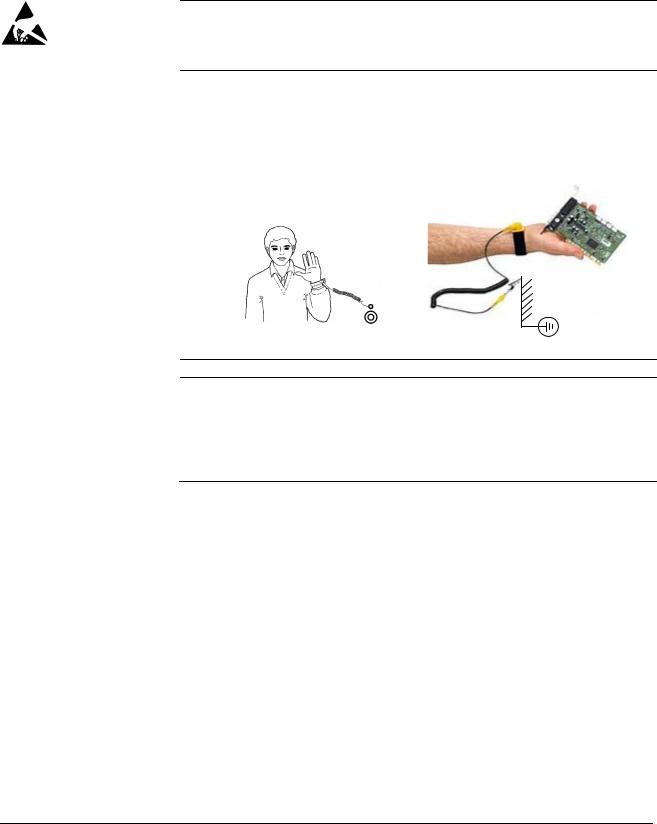
WARNING! The printed circuit boards contain components sensitive to electrostatic discharge. Wear a grounding wrist band when handling the boards. Do not touch the boards unnecessarily.
Use grounding strip:
ABB order no.: 3ADV050035P0001
WARNING! Handle the fiber optic cables with care. When unplugging optic cables, always grab the connector, not the cable itself. Do not touch the ends of the fibers with bare hands as the fiber is extremely sensitive to dirt. The minimum allowed bend radius is 35 mm (1.38 in.).
Safety instructions
3ADW000195R0501 DCS800 Service Manual e e

9
Mechanical installation
These notes are intended for all who install the drive. Handle the unit carefully to avoid damage and injury.
WARNING!
•DCS800 sizes D4 … D7: The drive is heavy. Do not lift it alone. Do not lift the unit by the front cover. Place units D4 and D5 only on its back.
DCS800 sizes D5 … D7: The drive is heavy. Lift the drive by the lifting lugs only. Do not tilt the unit. The unit will overturn from a tilt of about 6 degrees.
•Make sure that dust from drilling does not enter the drive when installing. Electrically conductive dust inside the unit may cause damage or lead to malfunction.
•Ensure sufficient cooling.
•Do not fasten the drive by riveting or welding.
Safety instructions
3ADW000195R0501 DCS800 Service Manual e e 3ADW000195R0101 DCS800 Service Manual e a

10
Operation
These warnings are intended for all who plan the operation of the drive or operate the drive. Ignoring the instructions can cause physical injury or death and/or damage to the equipment.
WARNING!
•Before adjusting the drive and putting it into service, make sure that the motor and all driven equipment are suitable for operation throughout the speed range provided by the drive. The drive can be adjusted to operate the motor at speeds above and below the base speed.
•Do not control the motor with the disconnecting device
(disconnecting mains); instead, use the control panel keys  and
and  , or commands via the I/O board of the drive.
•Mains connection
You can use a disconnect switch (with fuses) to disconnect the electrical components of the drive from the mains for installation and maintenance work. The type of disconnect switch used must be as per EN 60947-3, Class B, so as to comply with EU regulations, or a circuit-breaker type which switches off the load circuit by means of an auxiliary contact causing the breaker’s main contacts to open. The mains disconnect must be locked in its «OPEN» position during any installation and maintenance work.
•EMERGENCY STOP buttons must be installed at each control desk and at all other control panels requiring an emergency stop function. Pressing the STOP button on the control panel of the drive will neither cause an emergency stop of the motor, nor will the drive be disconnected from any dangerous potential.
To avoid unintentional operating states, or to shut the unit down in case of any imminent danger according to the standards in the safety instructions it is not sufficient to merely shut down the drive via signals «RUN», «drive OFF» or «Emergency Stop» respectively «control panel» or «PC tool».
•Intended use
The operating instructions cannot take into consideration every possible case of configuration, operation or maintenance. Thus, they mainly give such advice only, which is required by qualified personnel for normal operation of the machines and devices in industrial installations.
If in special cases the electrical machines and devices are intended for use in non-industrial installations — which may require stricter safety regulations (e.g. protection against contact by children or similar) — these additional safety measures for the installation must be provided by the customer during assembly.
Safety instructions
3ADW000195R0501 DCS800 Service Manual e e
![]()
11
Note:
•When the control location is not set to Local (L not shown in the status row of the display), the stop key on the control panel will not
stop the drive. To stop the drive using the control panel, press the LOC/REM key and then the stop key  .
.
Safety instructions
3ADW000195R0501 DCS800 Service Manual e e 3ADW000195R0101 DCS800 Service Manual e a

3ADW000195R0501 DCS800 Service Manual e e

|
13 |
|
Table of contents |
|
|
Safety instructions |
5 |
|
What this chapter contains……………………………………………………………………………………………. |
5 |
|
To which products this chapter applies…………………………………………………………………………… |
5 |
|
Usage of warnings and notes ……………………………………………………………………………………….. |
5 |
|
Installation and maintenance work…………………………………………………………………………………. |
6 |
|
Grounding………………………………………………………………………………………………………… |
7 |
|
Mechanical installation…………………………………………………………………………………………………. |
9 |
|
Operation …………………………………………………………………………………………………………………. |
10 |
|
Table of contents |
13 |
|
Introduction |
16 |
|
How to use this manual………………………………………………………………………………………………. |
16 |
|
Contents of this manual ……………………………………………………………………………………………… |
16 |
|
Target group …………………………………………………………………………………………………………….. |
16 |
|
Associated publications ……………………………………………………………………………………………… |
16 |
|
Storage and transport ………………………………………………………………………………………………… |
17 |
|
Name plate and type code ………………………………………………………………………………………….. |
17 |
|
Type code ………………………………………………………………………………………………………………… |
18 |
|
Current and voltage ratings…………………………………………………………………………………………. |
19 |
|
Fault Tracing Thyristors |
21 |
|
Tools ……………………………………………………………………………………………………………………….. |
21 |
|
For commissioning and fault tracing…………………………………………………………………… |
21 |
|
Additionally for service and preventive maintenance ……………………………………………. |
22 |
|
How to detect a faulty thyristor…………………………………………………………………………………….. |
22 |
|
A fuse is blown ……………………………………………………………………………………………….. |
22 |
|
DC-current pulses measured by an oscilloscope …………………………………………………. |
23 |
|
Thyristor diagnosis ………………………………………………………………………………………….. |
23 |
|
Ripple monitor ………………………………………………………………………………………………… |
23 |
|
How to find a faulty thyristor………………………………………………………………………………………… |
24 |
|
Converters size D1 to D4 (20…1000 A)………………………………………………………………. |
24 |
|
Blown fuses ……………………………………………………………………………………………………. |
24 |
|
Converters size D5, D6, and D7 (900…5200 A) …………………………………………………… |
25 |
|
Blown fuses ……………………………………………………………………………………………………. |
25 |
|
Ripple monitor ………………………………………………………………………………………………… |
25 |
|
Handling the Semiconductors |
27 |
|
General Instruction how to handle the Semiconductors ………………………………………………….. |
27 |
|
Exchange of Thyristors for Size D1 to D4 |
29 |
|
Installation of OnBoard bridge and thyristor modules in converters size D1 to D4 |
|
|
(20…1000 A) …………………………………………………………………………………………………………….. |
29 |
|
Required Tools ……………………………………………………………………………………………….. |
29 |
|
Find faulty thyristor modules …………………………………………………………………………….. |
29 |
|
Remove faulty thyristor modules ……………………………………………………………………….. |
30 |
|
Install new thyristor modules …………………………………………………………………………….. |
34 |
|
Table of contents |
3ADW000195R0501 DCS800 Service Manual e e

|
14 |
||
|
Remove faulty OnBoard bridge (V1) …………………………………………………………………. |
36 |
|
|
Install new OnBoard bridge (V1) ………………………………………………………………………. |
36 |
|
|
OnBoard bridge (V1) and thyristor module location in DCS800-S01 (2-Q) units |
………. 37 |
|
|
OnBoard bridge (V1) and thyristor module location in DCS800-S02 (4-Q) units………. |
38 |
|
|
OnBoard bridge and thyristor module terminals ………………………………………………….. |
39 |
|
|
Exchange of Thyristors for Size D5 |
41 |
|
|
Installation of «Disc Type» thyristor in converters size D5 (900… |
2000 A) ………………………….. |
41 |
|
Required Tools ………………………………………………………………………………………………. |
41 |
|
|
Disk type thyristors …………………………………………………………………………………………. |
42 |
|
|
Find faulty thyristor …………………………………………………………………………………………. |
45 |
|
|
Remove faulty thyristor……………………………………………………………………………………. |
46 |
|
|
Install new thyristor…………………………………………………………………………………………. |
47 |
|
|
Exchange of Thyristors for Size D6 |
51 |
|
|
Installation of «Disc Type» thyristor in converters size D6 (1900… |
3000 A) ………………………… |
51 |
|
Required Tools ………………………………………………………………………………………………. |
51 |
|
|
Disk type thyristors …………………………………………………………………………………………. |
52 |
|
|
BCT thyristors………………………………………………………………………………………………… |
53 |
|
|
Find faulty thyristor …………………………………………………………………………………………. |
54 |
|
|
Remove faulty thyristor……………………………………………………………………………………. |
55 |
|
|
Install new thyristor…………………………………………………………………………………………. |
58 |
|
|
Exchange of Thyristors for Size D7 |
65 |
|
|
Installation of «Disc Type» thyristor in converters size D7 (2050… |
5200 A) ………………………… |
65 |
|
Required Tools ………………………………………………………………………………………………. |
65 |
|
|
Find faulty thyristor …………………………………………………………………………………………. |
66 |
|
|
Install new thyristor…………………………………………………………………………………………. |
69 |
|
|
Exchange of SDCS-CON-4 |
75 |
|
|
General …………………………………………………………………………………………………………………… |
75 |
|
|
Required Tools ………………………………………………………………………………………………. |
75 |
|
|
Overview SDCS-CON-4 exchange……………………………………………………………………. |
75 |
|
|
Service |
83 |
|
|
How to remove the converter fans in frames D1 to D3 (two fans) ……………………………………. |
83 |
|
|
How to remove the converter fans in a frame D3 (four fans) …………………………………………… |
87 |
|
|
How to remove the converter fan in a frame D6 ……………………………………………………………. |
92 |
|
|
How to remove the converter fan in a frame D7 ……………………………………………………………. |
93 |
|
|
DCS800 firmware download ………………………………………………………………………………………. |
94 |
|
|
General…………………………………………………………………………………………………………. |
94 |
|
|
Download SDCS-CON-4 firmware…………………………………………………………………….. |
94 |
|
|
Add firmware or text files ……………………………………………………………………………….. |
107 |
|
|
Create a workspace………………………………………………………………………………………. |
114 |
|
|
Download SDCS-COM-8 firmware ………………………………………………………………….. |
129 |
|
|
Set type code …………………………………………………………………………………………………………. |
131 |
|
|
Type code table ……………………………………………………………………………………………. |
133 |
|
|
DC-Motor neutral zone adjustment ……………………………………………………………………………. |
134 |
|
|
Types concerned ………………………………………………………………………………………….. |
134 |
|
|
Summary …………………………………………………………………………………………………….. |
134 |
|
|
General……………………………………………………………………………………………………….. |
134 |
Table of contents
3ADW000195R0501 DCS800 Service Manual e e

|
15 |
|
|
Preventive Maintenance |
135 |
|
Recommended regular maintenance |
…………………………………………………………………………..136 |
|
Maintenance schedule ……………………………………………………………………………………………… |
136 |
|
Annual preventive maintenance…………………………………………………………………………………. |
137 |
|
3 years preventive maintenance ………………………………………………………………………………… |
140 |
|
6 years preventive maintenance ………………………………………………………………………………… |
141 |
|
9 years preventive maintenance ………………………………………………………………………………… |
143 |
|
Appendix A — Spare Parts List |
145 |
Table of contents
3ADW000195R0501 DCS800 Service Manual e e

16
Introduction
How to use this manual
The purpose of this service manual is to provide detailed information on how to service power converters from the DCS800 series.
Contents of this manual
Safety instructions
This chapter is located at the beginning of this manual.
Introduction
This chapter informs about the contents and the use of this manual as well as the boundary conditions applying and the thyristor power converter rating plate.
Fault Tracing Thyristors
This chapter describes how to detect and select a faulty thyristor.
Handling the Semiconductors
This chapter describes the handling of thyristors and thyristor modules.
Exchange of Thyristors of Sizes D1 to D4
This chapter describes the exchange of thyristors in converters sizes D1 to D4.
Exchange of Thyristors of Size D5
This chapter describes the exchange of thyristors in converters size D5.
Exchange of Thyristors of Size D6
This chapter describes the exchange of thyristors in converters size D6.
Exchange of Thyristors of Size D7
This chapter describes the exchange of thyristors in converters size D7
Exchange of SDCS-CON-4
This chapter describes the exchange of a SDCS-CON-4
Service
This chapter contains hardware information and technical hints.
Preventive Maintenance
This chapter describes the measures for preventive maintenance of the thyristor converters.
Appendix A Spare Parts list
The Appendix A contains the spare parts list of the converters.
Target group
This manual is designed to help those responsible for planning, installing, starting up and servicing the thyristor power converter.
These people should possess:
basic knowledge of physics and electrical engineering, electrical wiring principles, components and symbols used in electrical engineering, and
basic experience with DC drives and products.
Associated publications
A list of associated publications is published on the inner page of this manual’s cover, see DCS800 Drive Manuals. Here is a list of the most important ones:
The DCS800 Hardware Manual (3ADW000194) describes all hardware
Introduction
3ADW000195R0501 DCS800 Service Manual e e

17
components of the DCS800, their connections and settings (e.g. jumpers)
The DCS800 Firmware Description (3ADW000193) gives an overview of the
DCS800 firmware, describes all parameters, describes the function of the DCS Control Panel, gives support in case of faults and alarms and gives information about communication.
The above listed documentation can be found on the CD-ROM being attached to the DCS800 Quick Guide (3ADW000191).
Storage and transport
If the unit has been in storage prior to installation or is transported to another location, care must be taken to ensure that the environmental conditions are complied with (see Hardware Manual).
Name plate and type code
For purposes of identification, each thyristor power converter is fitted with name plates, stating the type code and the serial number, which serve for each unit’s individual identification.
The type code contains information about the characteristics and the configuration of the unit.
|
ABB Automation Products |
U1 |
3 525 V |
U2 |
610 V |
|||||||
|
20 A |
Made in Germany |
||||||||||
|
Type: DCS800-S02-0025-05 |
I1 |
I2 |
25 A |
||||||||
|
+K454 |
|||||||||||
|
Ser No: 0025421A06294264 |
f1 |
50/60 Hz |
If |
6 A |
+J409 |
||||||
|
SCCR |
65 kA |
Fan |
—- |
||||||||
|
Production year |
Rated input voltage |
Rated output current |
|
|
2006 and week 29 |
Rated input current |
Rated internal field |
exciter current Rated fan voltage
Plus code
Example of a name plate
Introduction
3ADW000195R0501 DCS800 Service Manual e e

18
Type code
The type code contains information on the specifications and configuration of the drive. The first digits from left express the basic configuration (e.g. DCS800-S01- 2005). The optional selections are given thereafter, on the name plate by plus code. The main selections are described below. Not all selections are available for all types.
|
Type code |
D C S 8 0 |
0 — A A X — Y Y |
Y Y — Z Z |
— plus code |
||||||||||
|
Position |
A X |
Y |
Z |
B |
||||||||||
|
Position |
Plus code |
|||||||||||||
|
Product series |
DCS800 |
|||||||||||||
|
A |
Type |
S0 = Standard converter module IP00 |
||||||||||||
|
R0 = Rebuild system |
||||||||||||||
|
E0 = Panel solution |
||||||||||||||
|
A0 = Enclosed converter |
||||||||||||||
|
X |
Bridge type |
1 = Single bridge (2-Q) |
||||||||||||
|
2 = 2 anti parallel bridges (4-Q) |
||||||||||||||
|
Y |
Rated DC current |
YYYY = Rated current (e.g. 0025 = 25 ADC) |
||||||||||||
|
ZZ |
Rated AC voltage |
04 = 400 VAC |
||||||||||||
|
05 = 525 VAC |
||||||||||||||
|
06 = 600 VAC |
||||||||||||||
|
07 = 690 VAC |
||||||||||||||
|
08 = 800 VAC |
||||||||||||||
|
10 = 990 VAC |
||||||||||||||
|
12 = 1200 VAC |
||||||||||||||
|
B |
Power connection |
— = Standard D1 … D6 |
||||||||||||
|
L = Left side D7 |
||||||||||||||
|
R = Right side D7 |
||||||||||||||
|
a = Second thyristor type D5, D6 |
||||||||||||||
|
Internal field exciter |
+S164 |
With internal field exciter, external supply (only D5:25 A, Rebuild kit: 25 A/16 A) |
||||||||||||
|
configuration |
+0S163 |
Without internal field exciter (only D1 … D4) |
||||||||||||
|
Fan voltage |
Size D4 |
|||||||||||||
|
Standard fan voltage: |
230 V / 1-ph |
|||||||||||||
|
+S171 |
Additional fan voltage: |
115 V / 1-ph |
||||||||||||
|
Size D6 |
||||||||||||||
|
Standard fan voltage for 400 V / 500 V / 800 V units: |
400-500 V / 3-ph |
|||||||||||||
|
Standard fan voltage for 600 V / 690 V units: |
525-690 V / 3-ph |
|||||||||||||
|
+S172 |
Additional fan voltage for 600-690 V units: |
400-500 V / 3-ph |
||||||||||||
|
Current measurement |
+S175 |
SDCS-CMA-2 for sizes D5 to D7 |
||||||||||||
|
Voltage measurement |
+S186 |
120 V SDCS-SUB-4 for sizes D1 … D4 |
||||||||||||
|
+S180 |
600 V for sizes D6 and D7 |
|||||||||||||
|
+S181 |
690 V for sizes D6 and D7 |
|||||||||||||
|
+S182 |
800 V for sizes D6 and D7. |
|||||||||||||
|
+S183 |
990 V for sizes D6 and D7. |
|||||||||||||
|
+S189 |
Galvanic isolation for sizes D6 and D7 |
|||||||||||||
|
SDCS-DSL-4 |
+S199 |
With SDCS-DSL-4 |
||||||||||||
|
+0S199 |
Without SDCS-DSL-4 |
|||||||||||||
|
+ plug-in options |
||||||||||||||
|
DCS Control Panel |
0J400 |
Without DCS Control Panel |
||||||||||||
|
J409 |
Door mounting Kit (cable length 3 m) |
|||||||||||||
|
Fieldbus |
K454 |
Profibus RPBA |
||||||||||||
|
K451 |
DeviceNet RDNA |
|||||||||||||
|
K466 |
Ethernet IP + Modbus TCP RETA |
|||||||||||||
|
K458 |
Modbus RMBA |
|||||||||||||
|
I/O and DDCS |
L500 |
Analogue Extension RAIO |
||||||||||||
|
L501 |
Digital Extension RDIO |
|||||||||||||
|
L508 |
DDCS Communication board (10 Mbaud CH0) SDCS-COM-81 |
|||||||||||||
|
L509 |
DDCS Communication board (5 Mbaud CH0) SDCS-COM-82 |
Introduction
3ADW000195R0501 DCS800 Service Manual e e

19
The technical data and specifications are valid as of going to press. ABB reserves the right to make subsequent alterations.
If you have any questions concerning your drive system, please contact your local ABB agent.
Current and voltage ratings
|
Unit size |
2-Q rated current |
4-Q rated current |
Supply voltage [VAC] |
||||||
|
DCS800-01 [ADC] |
DCS800-02 [ADC] |
||||||||
|
400 |
525 |
600 |
690 |
800 |
990 |
1200 |
|||
|
D1 |
20 |
25 |
X |
X |
|||||
|
45 |
50 |
X |
X |
||||||
|
65 |
75 |
X |
X |
||||||
|
90 |
100 |
X |
X |
||||||
|
125 |
140 |
X |
X |
||||||
|
D2 |
180 |
200 |
X |
X |
|||||
|
230 |
260 |
X |
X |
||||||
|
D3 |
315 |
350 |
X |
X |
X |
||||
|
405 |
450 |
X |
X |
||||||
|
470 |
520 |
X |
X |
||||||
|
D4 |
610 |
680 |
X |
X |
X |
||||
|
740 |
820 |
X |
X |
||||||
|
900 |
1000 |
X |
X |
||||||
|
D5 |
900 |
900 |
X |
X |
|||||
|
1200 |
1200 |
X |
X |
||||||
|
1500 |
1500 |
X |
X |
X |
X |
||||
|
2000 |
2000 |
X |
X |
X1 |
X1 |
||||
|
D6 |
1900 |
1900 |
X |
||||||
|
2050 |
2050 |
X |
X |
X |
|||||
|
2500 |
2500 |
X |
X |
X |
X |
X |
|||
|
3000 |
3000 |
X |
X |
X |
X |
X |
|||
|
D7 |
2050 |
2050 |
X |
||||||
|
2600 |
2600 |
X |
X |
||||||
|
3300 |
3300 |
X |
X |
X |
X |
X |
X |
X |
|
|
4000 |
4000 |
X |
X |
X |
X |
X |
X |
X |
|
|
4800 |
4800 |
X |
X |
X |
|||||
|
5200 |
5200 |
X |
X |
1 only available as 2-Q drive
Introduction
3ADW000195R0501 DCS800 Service Manual e e

3ADW000195R0501 DCS800 Service Manual e e
![]()
21
Fault Tracing Thyristors
Tools
For commissioning and fault tracing
Following software tools are mandatory:
DriveWindow Light including commissioning wizard and DWL AP for Adaptive Program and
DriveWindow for fast drive monitoring using SDCS-COM-8.
Following tools are mandatory in addition to standard tools:
An oscilloscope including memory function with either galvanically isolating transformer or isolating amplifier (probe) for safe measurements. It can also be a hand held (portable) oscilloscope.
A clamp on current probe. In case the scaling of the DC load current needs to be checked it must be a DC clamp on current probe.
A voltmeter (at least CAT III 1000 V):
1000 V probes and test leads:
An ESD-field service kit (ABB Service Finland code 0001ESD / MS-Antistatic):
Make sure that all equipment in use is suitable for the voltage level applied to the power part!
Fault Tracing Thyristors
3ADW0000195R0501DCS8000ServiceManualeeee

22
Additionally for service and preventive maintenance
Following additional tools are mandatory for cleaning:
An ESD safe blower / ESD vacuum cleaner (ABB Service Finland code 0006ESD / MUNTZ 555-ESD-S-E):
How to detect a faulty thyristor
Thyristor problems can be noticed differently:
A fuse is blown
This is an indication, that a strong overcurrent has happened due to one of the following reasons:
An internal short circuit between the phases (line side) because of a defective thyristor (short circuit inside a thyristor from anode to cathode).
An internal short circuit between the phases (line side) because of circulating current in a 4-Q converter (malfunction of the control electronics, no thyristor defective).
An external short circuit at the DC terminals of the converter without sufficient impedance.
A commutation fault during generating (active braking with high current, high EMF and with low AC voltage) of a 4-Q converter.
Note:
In case of parallel fuses: If one of the parallel fuses is blown, all parallel fuses have to be changed. The ‘undamaged’ fuses might be ‘half-blown’ and will blow with the next high current.
Fault Tracing Thyristors
3ADW000195R0501 DCS800 Service Manual e e

23
DC-current pulses measured by an oscilloscope
Connect an oscilloscope to the fixed AO I-act (X4:9/10 on the SDCS-CON-4 or X4:5/6 on the SDCS-IOB-3) and check for the proper amount of current pulses:
Six current pulses in positive direction
There should be six current pulses in positive direction.
In case of a 4-Q converter also the six current pulses for the negative direction have to be checked.
Thyristor diagnosis
Also the thyristor diagnosis provided by the firmware can be used:
Switch the drive to local mode (DriveWindow, DriveWindow Light, DCS Control Panel or local I/O).
Start the thyristor diagnosis by means of ServiceMode (99.06) = ThyDiagnosis and set On and Run within 20 s.
During the thyristor diagnosis the main contactor will be closed and the thyristors are checked. The field current is not released while the thyristor diagnosis is active and thus the motor should not turn.
When the thyristor diagnosis is finished check Diagnosis (9.11) for details.
Ripple monitor
The ripple monitor indicates that the ripple of the DC current is much higher than normal. In such a case, most often one thyristor does not work. It’s missing current contribution causes a deep dip in the direct current.
The structure of the current loop (current controller) will force the other thyristors to compensate the dip by a certain overcurrent in order to keep the average current constant. Such a compensation results in a ripple monitoring fault during motoring mode operation with 90°.
The reason for a current less thyristor may be:
Fault Tracing Thyristors

24
A fuse has disconnected one of the six thyristors. This is possible only for converters with 900 … 5200 A (six internal branch fuses). A converter with three external fuses stops working completely at once when one of the three AC input fuses interrupts a phase input of the converter.
A thyristor does not get firing pulses or does not react to firing pulses.
The current controller may be totally mismatched to the DC load.
The AC mains network is causing that fault message. In this case, asymmetrical phase shift, uneven phase voltage or critical designed power factor correction equipment or harmonic reduction equipment can be the reason.
How to find a faulty thyristor
If a blown fuse is suspected in the converter, the problem is caused most often by a faulty thyristor. To make sure, that a thyristor is the reason and needs to be exchanged fault tracing must be done in two different ways, depending on the size of the converter.
In general, make sure, that all safety instructions, given within this manual or within the safety instructions, related to the machine or the application itself, are obeyed.
Converters size D1 to D4 (20…1000 A)
These converters require semiconductor fuses in the 3 AC lines.
The converter must be disconnected from the mains.
One motor armature cable should be disconnected from the converter.
Blown fuses
Using the OHM function of a normal multimeter, measurements must be made from each AC terminal to each DC terminal (U1 to C1, V1 to C1, W1 to C1, U1 to D1, V1 to D1 and W1 to D1; see picture Anti-parallel B6-bridges with
branching fuses on page 45). Normally, every measurement should show high resistance (> 1 k ).
Target: find a short circuit, indicated by low resistance ( <1 ) (destroyed thyristor).
If the converter is designed with half-bridge thyristor modules, then a module consists of two anti-parallel thyristors. In this case it is sufficient to know which thyristor pair or module has a defective thyristor because the complete module must be replaced.
After a thyristor module is replaced, the above mentioned measurement should be done another time to make sure that all faulty thyristors have been detected!
Note:
The RC circuit could also cause 0 result for a short time.
The measurement, showing less resistance than 1 should be made a second time with test leads applied to the terminals with opposite polarity; if this measurement shows the same result, one or two thyristors located in that path are faulty; they need to be replaced.
Fault Tracing Thyristors
3ADW000195R0501 DCS800 Service Manual e e

25
Converters size D5, D6, and D7 (900…5200 A)
These converters are equipped with fuses in the branches of the power part.
The converter must be disconnected from the mains.
Blown fuses
In case of a blown fuse, the faulty thyristor or the faulty pair of thyristors are already isolated at one side from the others and therefore the faulty branch is known (see picture Anti-parallel B6-bridges with branching fuses on page 45).
The OHM test should be performed, when the thyristor is still clamped. Outside the converter a special thyristor clamping device is needed.
For 4-Q converters with anti-parallel thyristors or BCT’s:
The selection of a forward or reverse thyristor or BCT (Bidirectional-Controlled-Thyristor) is done during the disassembly. Continue with related part Exchange of Thyristors for Size D5, D6 or D7 section Find faulty thyristor.
After a thyristor was replaced, the OHM test should be done another time to make sure that all faulty thyristors have been detected! If the motor is still connected to the converter the result of the measurement may be wrong.
Ripple monitor
If the ripple monitor fault occurred, a fault tracing as described above must be carried out:
Check the fuses and the thyristors, according to the statements before.
If the power section seems to be ok, but still one or more thyristors don’t take current, something went wrong in between the firing pulse generation and the thyristor’s gate; in this case check:
Is a firing pulse present on the primary side of the firing pulse transformer?
Is a firing pulse present on the secondary side of the firing pulse transformer?
Is the firing pulse transferred to the gate of the thyristor? Are there all electrical connections still healthy?
Can the thyristor be fired with the applied firing pulse? Is the pulse form of the firing pulse identical at all measuring positions?
Check the settings of the current controller.
Check the AC mains network by taking recordings of the line voltage and current at all 3 phases at the same time.
Fault Tracing Thyristors

26
Fault Tracing Thyristors
3ADW000195R0501 DCS800 Service Manual e e

27
Handling the Semiconductors
General Instruction how to handle the Semiconductors
Thyristor modules, busbars and fuses have to be mounted with the correct torque using a torque screw driver or torque wrench.
In converters sizes D5 (900 … 2000 A), D6 (1900 … 3000 A) and D7 (2050 … 5200 A) the mounting force is indicated by an indicating spring welded to the mounting clamp, which is inside the unit.
Always mark suspected damaged components clearly after removing them from the circuit, to avoid confusion with «good» components.
When removing a damaged semiconductor, write down how and where it was installed (direction, location, connected gate leads and with BCT’s the position of the gate connectors).
Check that the new and old components have the same type designation or that the new component can replace the old one. A semiconductor can be replaced by different compatible semiconductor according to the codes in the manufacturers’ table.
Semiconductor components are high-precision products. All unnecessary used tools and objects might damage the easily dented and scratched surfaces of the semiconductors.
1.Keep new semiconductors as long as possible in their original packages.
2.Use protective gloves if possible.
3.Clean work area and hands frequently.
4.Use good illumination.
Handling the Semiconductors
3ADW000195R0501 DCS800 Service Manual e e

28
Handling the Semiconductors
3ADW000195R0501 DCS800 Service Manual e e

29
Exchange of Thyristors for Size D1 to D4
Installation of OnBoard bridge and thyristor modules in converters size
D1 to D4 (20…1000 A)
All DCS800 size D1 to D4 are equipped with an OnBoard bridge (excitation) and thyristor modules. In order to keep the operating temperature of the semiconductor module low, the joint between the heat sink and the module should have a good heat conducting ability. The electrical conductivity of the connectors must also be good. For this reason the following instructions must be observed with particular care.
Required Tools
Special tools or material needed in addition to standard tools for the exchange of thyristor modules:
|
Torx screwdrivers: |
TX10, TX20, TX25 |
|
|
Torque spanner: |
mounting torques for the OnBoard bridge and the |
|
|
thyristor modules to heat sink and electrical |
||
|
connections see table Nominal mounting torque for |
||
|
OnBoard bridge and thyristor modules on page 35 |
Screws are metric type; use appropriate nuts
Tissue paper
Solvent (e.g. ethanol)
Thermal joint compound: type Berulub FZ1 E3
|
(grease) |
|
|
Manufacturer: |
Carl Bechem GmbH, 58089 Hagen |
|
ABB Service: |
GHSN 390 011 P 0051 |
|
or |
|
|
thermal joint compound: |
type WLPF 20 (10 ml) |
|
ABB Service: |
GHSN 390 011 P 10 |
Before the work is started, disconnect the converter from the power supply completely, then check the voltage free condition and make sure, everything is located in an electrical and mechanical safe condition!
Find faulty thyristor modules
See Fault Tracing Thyristors of this publication.
Exchange of Thyristors for Size D1 to D4
3ADW000195R0501 DCS800 Service Manual e e

30
Remove faulty thyristor modules
1. Remove the DCS Control Panel and design cover:
 Remove DCS Control Panel
Depress the locks by means of a screwdriver to remove the design cover
Remove design cover
2.Remove all plug in options on the intermediate cover e.g.:
serial communication modules (R-type),
extension I/O modules (RAIO, RDIO),
extension modules for second encoder (RTAC) or resolver (RRIA),
communication board (SDCS-COM-8),
isolated I/O (SDCS-IOB-2x, SDCS-IOB-3) and
SDCS-MEM-8 (Memory Card).
3.Remove the intermediate cover by depressing the two locks on the upper right and left hand side of the cover:
Depress the locks to remove the design cover
Remove all options, so that the intermediate cover is empty
Remove plug in options
Exchange of Thyristors for Size D1 to D4
3ADW000195R0501 DCS800 Service Manual e e
![]()
31
4.Disconnect all I/O plugs (X3 to X7) at the SDCS-CON-4 and the plugs at the SDCS-DSL-4 board, if used (X51 to X54):
Disconnect all plugs from SDCS-
CON-4 and SDCS-DSL-4 boards
Disconnect all plugs
5. Remove the grounding plug and the holding screw at the electronic tray:
Remove the grounding plug and the holding screw
Remove grounding and screws
Exchange of Thyristors for Size D1 to D4
3ADW000195R0501 DCS800 Service Manual e e

32
6.To unhinge the electronic tray including the SDCS-CON-4 pull it up and then out. Before remove tray completely unplug the flat cables (X12, X13, X37):
Electronic tray with SDCS-CON-4
Remove flat cables
Unhinge electronic tray
7. Remove all cables and plugs at the SDCS-PIN-4:
Keep winding direction and amount of windings for T100 in mind.
T100
Remove all cables and plugs
How to handle X8:
X8
use screw driver
Remove cables at the SDCS-PIN-4
Attention:
Write down the winding direction of the cable through T100!
D1: thread the wire 4 times through the hole in T100 (that equals 3 loops)
D2 — D4: thread the wire 1 time through the hole in T100 (that equals no loops)
Exchange of Thyristors for Size D1 to D4
3ADW000195R0501 DCS800 Service Manual e e

33
8. Remove the SDCS-PIN-4 board:
|
OnBoard field exciter |
Snubber resistor |
||||||
|
bridge module |
|||||||
|
Thyristor modules |
|||||||
|
Current transformer |
Temperature sensor |
|
Remove SDCS-PIN-4
9.Remove the gate leads from the faulty thyristor module and mark the connectors clearly.
10.Remove the busbars necessary to get full access to the faulty thyristor module.
11.If a current transformer must be removed, mark its position and the connections clearly.
Note:
Remove only as many parts as needed around the faulty thyristor module.
12.Remove the faulty thyristor module and mark it clearly as defective.
Exchange of Thyristors for Size D1 to D4
3ADW000195R0501 DCS800 Service Manual e e

34
Install new thyristor modules
1.Ensure that the new thyristor module is of the correct type (see appendix A of this manual).
2.Remove old heat conducting compound (grease) from the heat sink. Clean the mounting surfaces (heat sink and thyristor module) with an appropriate solvent (e.g. ethanol) by means of tissue paper. When the heat sink is clean, spread out the heat conducting compound with a rubber spatula or by hand.
3.Apply a thin layer of heat conducting compound to the new thyristor module:
Application of heat conducting compound
4.Spread the heat conducting compound evenly by moving the thyristor module forward and backward on the heat sink.
5.Tighten all clamping screws by hand until the screw heads touch the bottom of the thyristor module. Then tighten the screws to 2.0 Nm torque.
Note:
If the thyristor module is mounted by means of four screws, tighten the screws crosswise.
6.Tighten the screws to nominal torque according to table Nominal mounting torque for OnBoard bridge and thyristor modules page 35.
Exchange of Thyristors for Size D1 to D4
3ADW000195R0501 DCS800 Service Manual e e

35
|
OnBoard bridge and thyristor modules |
Nominal mounting torque |
|||
|
Size |
Type |
Electrical |
Thyristor module |
|
|
connections |
to heat sink |
|||
|
29 mm bridge block |
VVZF 70-16 |
— |
5 Nm |
|
|
20 mm block |
SKKT 27, 42, 57, 106 |
3 Nm |
5 Nm |
|
|
20 mm block |
MCC 26, 44, 56, 95 |
2.5 … 4 Nm |
2.5 … 4 Nm |
|
|
34 mm block |
MCC 162 |
4.45 … 5.5 Nm |
2.25 … 2.75 Nm |
|
|
34 mm block |
SKKT 162 |
5 Nm |
5 Nm |
|
|
34 mm block |
TT 162 |
6 Nm |
6 Nm |
|
|
50 mm block |
MCC 255 |
11 … 13 Nm |
4.5 … 7 Nm |
|
|
50 mm block |
TT 250, 330 |
12 Nm |
6 Nm |
|
|
60 mm block |
TT 425, 570 |
12 Nm |
6 Nm |
|
Nominal mounting torque for OnBoard bridge and thyristor modules
7.Reinstall the current transformer, make sure, its position is correct.
8.Reinstall the busbars, make sure, the correct torque is applied according to table Nominal mounting torque for OnBoard bridge and thyristor modules on page 35.
9.Reconnect all gate leads to the thyristor module.
10.Reinstall the SDCS-PIN-4 board.
11.Reconnect all cables and plugs at the SDCS-PIN-4:
snubber resistor (X30, X31),
temperature sensor (X22),
current transformers (X3, X4, X5),
OnBoard excitation (X8, X9, X11), use proper winding direction and amount of windings for T100
gate leads (first X16, X18 then X15, X17),
OnBoard excitation line voltage (X1, X2, X7),
all plugs (X10, X96, X99) and
all flat cables (X12, X13, X37), use the lock connectors at the SDCS-PIN-4
12.Reconnect the flat cables at the SDCS-CON-4 (X12, X13, X37) and re-hinge the electronic tray.
13.Reconnect the grounding plug and the holding screw at the electronic tray.
14.Reconnect all I/O plugs at the SDCS-CON-4 (X3 to X7) and the plugs at the SDCS-DSL-4 (X51 to X54).
15.Reinstall the intermediate cover, all plug in options and the design cover.
Exchange of Thyristors for Size D1 to D4
3ADW000195R0501 DCS800 Service Manual e e

36
Remove faulty OnBoard bridge (V1)
1.Follow the instructions Remove faulty thyristor modules until step 8 is done.
2.Remove all connectors from the faulty OnBoard bridge and mark the connectors clearly.
3.Remove the faulty OnBoard bridge and mark it clearly as defective.
Install new OnBoard bridge (V1)
1.Ensure that the new OnBoard bridge is of the correct type (see appendix A of this manual).
2.Remove old heat conducting compound (grease) from the heat sink. Clean the mounting surfaces (heat sink and OnBoard bridge) with an appropriate solvent (e.g. ethanol) by means of tissue paper. When the heat sink is clean, spread out the heat conducting compound with a rubber spatula or by hand.
3.Apply a thin layer of heat conducting compound to the new OnBoard bridge.
4.Spread the heat conducting compound evenly by moving the OnBoard bridge forward and backward on the heat sink.
5.Tighten all clamping screws by hand until the screw heads touch the bottom of the thyristor module. Then tighten the screws to 2.0 Nm torque.
6.Tighten the screws to nominal torque according to table Nominal mounting torque for OnBoard bridge and thyristor modules on page 35.
7.Reconnect all connectors to the OnBoard bridge.
8.Follow the instructions Install new thyristor modules beginning with step 10.
Exchange of Thyristors for Size D1 to D4
3ADW000195R0501 DCS800 Service Manual e e

37
OnBoard bridge (V1) and thyristor module location in DCS800-S01 (2-Q) units
DCS800-S01-0020 … 0180
V1
|
V14/V11 |
|
| <![if ! IE]>
<![endif]>K2 G2 |
<![if ! IE]>
<![endif]>K1 G1 |
|
V16/V13 |
|
| <![if ! IE]>
<![endif]>K2 G2 |
<![if ! IE]>
<![endif]>K1 G1 |
|
V12/V15 |
|
| <![if ! IE]>
<![endif]>K2 G2 |
<![if ! IE]>
<![endif]>K1 G1 |
|
V1 |
|
V14/V11 |
| <![if ! IE]>
<![endif]>K2 G2 G1 K1 |
| <![if ! IE]>
<![endif]>A |
| <![if ! IE]>
<![endif]>K |
| <![if ! IE]>
<![endif]>AK |
DCS800-S01-0315 … 0470
|
V16/V13 |
| <![if ! IE]>
<![endif]>K2 G2 G1 K1 |
| <![if ! IE]>
<![endif]>A |
| <![if ! IE]>
<![endif]>K |
| <![if ! IE]>
<![endif]>AK |
|
V12/V15 |
| <![if ! IE]>
<![endif]>K2 G2 G1 K1 |
| <![if ! IE]>
<![endif]>A |
| <![if ! IE]>
<![endif]>K |
| <![if ! IE]>
<![endif]>AK |
|
V1 |
|
V14/V11 |
| <![if ! IE]>
<![endif]>A |
| <![if ! IE]>
<![endif]>K |
| <![if ! IE]>
<![endif]>AK |
DCS800-S01-0610 … 0900
|
V16/V13 |
| <![if ! IE]>
<![endif]>A |
| <![if ! IE]>
<![endif]>K |
| <![if ! IE]>
<![endif]>AK |
|
V12/V15 |
| <![if ! IE]>
<![endif]>A |
| <![if ! IE]>
<![endif]>K |
| <![if ! IE]>
<![endif]>AK |
DCS800 loc of mod 1Q.dsf
Location of the OnBoard bridge and thyristor modules in DCS800-S01 (2-Q) units
Note:
This drawing is only showing the location of the OnBoard bridge and thyristor modules, the actual converter module size is different!
Exchange of Thyristors for Size D1 to D4
3ADW000195R0501 DCS800 Service Manual e e

38
OnBoard bridge (V1) and thyristor module location in DCS800-S02 (4-Q) units
DCS800-S02-0025 … 0200
V1
|
V11/V24 |
V13/V26 |
V15/V22 |
|||||||
|
DCS800-S02-0350 … 0520 |
|||||||||
|
V1 |
|||||||||
|
V11 |
K1 |
K2 |
V14 |
||||||
|
G1 |
A |
K |
AK |
AK |
K |
A |
G2 |
||
|
G2 |
G1 |
||||||||
|
V24 |
K2 |
K1 |
V21 |
||||||
|
V15 |
K1 |
K2 |
V12 |
||||||
|
G1 |
A |
K |
AK |
AK |
K |
A |
G2 |
||
|
V22 |
G2 |
G1 |
V25 |
||||||
|
K2 |
K1 |
||||||||
|
V13 |
K1 |
K2 |
V16 |
||||||
|
G1 |
A |
K |
AK |
AK |
K |
A |
G2 |
||
|
V26 |
G2 |
G1 |
V23 |
||||||
|
K2 |
K1 |
||||||||
DCS800-S02-0260
V1
| <![if ! IE]>
<![endif]>G1 K1 |
<![if ! IE]>
<![endif]>G2 K2 |
|
V11/V24 |
|
V14/V21 |
|
| <![if ! IE]>
<![endif]>K2 G2 |
<![if ! IE]>
<![endif]>K1 G1 |
| <![if ! IE]>
<![endif]>G1 K1 |
<![if ! IE]>
<![endif]>G2 K2 |
|
V13/V26 |
|
V16/V23 |
|
| <![if ! IE]>
<![endif]>K2 G2 |
<![if ! IE]>
<![endif]>K1 G1 |
| <![if ! IE]>
<![endif]>G1 K1 |
<![if ! IE]>
<![endif]>G2 K2 |
|
V15/V22 |
|
V12/V25 |
|
| <![if ! IE]>
<![endif]>K2 G2 |
<![if ! IE]>
<![endif]>K1 G1 |
DCS800-S01-0680 … 1000
|
V1 |
V26/V13 |
V22/V15 |
|
V24/V11 |
||
| <![if ! IE]>
<![endif]>A |
<![if ! IE]>
<![endif]>A |
<![if ! IE]>
<![endif]>A |
| <![if ! IE]>
<![endif]>K |
<![if ! IE]>
<![endif]>K |
<![if ! IE]>
<![endif]>K |
| <![if ! IE]>
<![endif]>AK |
<![if ! IE]>
<![endif]>AK |
<![if ! IE]>
<![endif]>AK |
| <![if ! IE]>
<![endif]>AK |
<![if ! IE]>
<![endif]>AK |
<![if ! IE]>
<![endif]>AK |
| <![if ! IE]>
<![endif]>K |
<![if ! IE]>
<![endif]>K |
<![if ! IE]>
<![endif]>K |
| <![if ! IE]>
<![endif]>A |
<![if ! IE]>
<![endif]>A |
<![if ! IE]>
<![endif]>A |
|
V21/V14 |
V23/V16 |
V25/V12 |
DCS800 loc of mod 4Q.dsf
Location of the OnBoard bridge and thyristor modules in DCS800-S02 (4-Q) units
Note:
This drawing is only showing the location of the OnBoard bridge and thyristor modules, the actual converter module size is different!
Exchange of Thyristors for Size D1 to D4
3ADW000195R0501 DCS800 Service Manual e e

39
OnBoard bridge and thyristor module terminals
The next figures show the terminals of the OnBoard bridge and all used thyristor modules. The terminal description is also stamped or marked by a sticker on the OnBoard bridge and all thyristor modules.
For all firing pulse cables is valid: Yellow is gate lead.
Red is cathode lead.
VVZF 70-16
|
(AK)(K) |
(A |
(AK)(K) |
(A |
||||
|
1 |
2 5 4 |
6 7 |
3 |
1 |
2 4 5 |
7 6 |
3 |
|
1 |
2 |
3 |
1 |
2 |
3 |
|
7 G |
6 G |
||||
|
6 K |
7 K |
||||
|
5 K |
4 K |
||||
|
4 G |
5 G |
||||
|
SKKT 27, 42, 57, 106 |
MCC26, 44, 56, 95 |
|
(AK) (K) |
(A) |
|||||
|
1 |
2 5 4 |
7 |
6 |
3 |
||
|
6 |
7 |
|||||
|
1 |
2 |
3 |
||||
|
6 |
7 |
|||||
|
5 |
4 |
4 |
5 |
|||
|
SKTT 162 |
||||||
|
MCC162 |
Exchange of Thyristors for Size D1 to D4
3ADW000195R0501 DCS800 Service Manual e e

40
|
AK |
K |
A |
||
|
K2 G2 |
||||
|
K1 G1 |
||||
|
TT 162 |
MCC255 |
|||
|
(A) |
(K) (AK) |
|||
|
AK K |
A 3 |
6G 7K |
5G 4K2 1 |
|
|
K1 G1 |
K2 |
G2 |
|
5G4K |
||||||
|
K2 |
3 |
1 |
||||
|
AK |
K |
A |
G2 |
2 |
||
|
G1 |
||||||
|
K1 |
||||||
|
6G7K |
Terminals of the OnBoard bridge and all thyristor modules
Exchange of Thyristors for Size D1 to D4
3ADW000195R0501 DCS800 Service Manual e e
![]()
TX10, TX20, TX25 13 Nm (M8)
25 Nm (M10)
50 Nm (M12)
41
Exchange of Thyristors for Size D5
Installation of «Disc Type» thyristor in converters size D5 (900…2000 A)
All DCS800 converters sizes D5/D6/D7 are equipped with disk type thyristors. The structure of the «Disc type» semiconductor component is such that it requires a certain compression force to operate. The prevention of overheating of the component essentially depends on a good heat dissipation between the semiconductor and the conducted heat sink. It is thus important that all joints have good thermal and electrical conduction.
Required Tools
Special tools or material needed in addition to standard tools for the exchange of thyristor modules:
Torx screwdrivers:
Torque spanner for electrical connections:
Screws are metric type; use appropriate nuts.
17 mm ring spanner for fuse and busbar connections.
17 mm ring spanner for press clamp.
Tissue paper / solvent (e.g. ethanol).
Thermal joint compound: type BECHEM-RHUS SU 2 (grease)
|
Manufacturer: |
Carl Bechem GmbH, 58089 Hagen |
|
ABB Service: |
GHSN 390 001 P 0001 |
|
Disassembly tool |
3ADT 621 023 P1 |
|
Note: |
For more detailed information about the wiring of the power part, see Hardware Manual.
Therefore strict observance of the build in instructions given below is of utmost importance. Make sure that the new component can replace the old one in accordance with the spare part list (see Appendix A).
Semiconductors and heat sinks are to be handled carefully to avoid scratches and other damage. Avoid touching the contact surfaces. Do not lift the semiconductor with the gate wire. Do not lift the semiconductor by touching the current contact surfaces. Do not damage the welding flange or the contact surface.
Before you start work, disconnect the converter completely from the power supply then check the voltage free condition and make sure, everything is located in an electrically and mechanically safe condition!
Exchange of Thyristors for Size D5
3ADW000195R0501 DCS800 Service Manual e e

42
Disk type thyristors
Some converter modules size D5 are equipped with different disc type thyristors. For easy identification the name plate of the converter module is marked with “a” after the voltage identification:
|
Converter with original |
U1 |
Converter with second |
|
thyristor type T459Nxxx |
thyristor type T460Nxxx |
|
|
Id code: DCA0012007P0001 |
Id code: 3ADC340105P0001 |
|
|
DCS800-S01-0900-06 |
3 ~ 600 VAC |
DCS800-S01-0900-06a |
|
DCS800-S02-0900-06 |
3 ~ 600 VAC |
DCS800-S02-0900-06a |
|
DCS800-S01-0900-07 |
3 ~ 690 VAC |
DCS800-S01-0900-07a |
|
DCS800-S02-0900-07 |
3 ~ 690 VAC |
DCS800-S02-0900-07a |
|
Converter with original |
U1 |
Converter with second |
|
thyristor type T589Nxxx |
thyristor type T590Nxxx |
|
|
Id code: DCA0012015P0001 |
Id code: 3ADC340106P0001 |
|
|
DCS800-S01-1200-04 |
3 ~ 400 VAC |
DCS800-S01-1200-04a |
|
DCS800-S02-1200-04 |
3 ~ 400 VAC |
DCS800-S02-1200-04a |
|
DCS800-S01-1200-05 |
3 ~ 525 VAC |
DCS800-S01-1200-05a |
|
DCS800-S02-1200-05 |
3 ~ 525 VAC |
DCS800-S02-1200-05a |
|
Parts list |
The current and voltage ratings of original and second thyristor type are the same, but the sizes of gate and cathode terminals are different. Thus it is not possible to interchange both thyristor types as spares.
Attention: Use always the correct spare thyristor!
Original thyristor type (900 A)
Converter with original thyristor type T459Nxxx Id code: DCA0012007P0001
Original thyristor type
Exchange of Thyristors for Size D5
3ADW000195R0501 DCS800 Service Manual e e

43
|
Gate (G): |
Faston 2.8 x 0.8 mm |
|
Cathode (HK): |
Faston 4.8 x 0.8 mm |
|
Conductive plate: |
Diameter 36 mm |
Second thyristor type (900 A)
Converter with second thyristor type T460Nxxx Id code: 3ADC340105P0001
|
Second thyristor type |
|
|
Gate (4): |
Round terminal D = 1.5 mm |
|
Cathode (5): |
Faston 4.8 x 0.5 mm |
|
Conductive plate: |
Diameter 36 mm |
Original thyristor type (1200 A)
Converter with original thyristor type T589Nxxx Id code: DCA0012015P0001
Original thyristor type
Exchange of Thyristors for Size D5
3ADW000195R0501 DCS800 Service Manual e e

44
|
Gate (G): |
Faston 2.8 x 0.8 mm |
|
Cathode (HK): |
Faston 4.8 x 0.8 mm |
|
Conductive plate: |
Diameter 36 mm |
Second thyristor type (1200 A)
Converter with second thyristor type T590Nxxx Id code: 3ADC340106P0001
|
Second thyristor type |
|
|
Gate (4): |
Round terminal D = 1.5 mm |
|
Cathode (5): |
Faston 4.8 x 0.5 mm |
|
Conductive plate: |
Diameter 36 mm |
Exchange of Thyristors for Size D5
3ADW000195R0501 DCS800 Service Manual e e

45
Find faulty thyristor
1.Find the defective branches by performing an OHM test (both polarities) between U1, V1, W1 and C1, D1 (see fig. Anti-parallel B6-bridges with branching fuses on page 45)
|
C1 (+) |
|||||
|
V11 |
V24 |
V13 |
V26 |
V15 |
V22 |
|
F11 |
F13 |
F15 |
branching fuse |
||
U1 
V1
W1
 branch
V14


 V21 V16


 V23
V23  V12
V12


 V25
V25
 D1 (-)
principle_B6_a.dsf
Anti-parallel B6-bridges with branching fuses
2.Disconnect the branching fuses of the defective branches.
3.Find the defective thyristors by performing an OHM test (both polarities) over their heat sinks.
4.In a 4—quadrant converter change both thyristors clamped between the same heatsinks at once.
Note:
Because “Disc Type” semiconductors need a certain compression force to operate properly, a measurement outside the clamped heat sinks might be wrong. To be sure which thyristor is broken change only one thyristor, clamp the heat sinks again and repeat step three.
Exchange of Thyristors for Size D5
3ADW000195R0501 DCS800 Service Manual e e

46
Remove faulty thyristor
1.Remove the screws of the DC – busbars and branch fuses preventing the stack to be prized open.
Note:
It depends on the location of the defective thyristor which DC – busbar and fuses have to be disconnected.
2.Write down the direction and location of the thyristors to be removed and mark their gate leads.
3.Remove the gate leads if possible.
4.Loosen the mounting clamp (see fig. Aluminum spring with welded indicating spring on page 47) at the top of the thyristor stack.
Attention: While loosen the mounting clamp the indicating spring must be pulled out a little, otherwise the spring will be damaged!
5.Attach the disassembly tool at the faulty thyristor and prize open the upper and lower heat sinks (see fig. How to use the disassembly tool page 46).
6.Remove the thyristors.
Attention: To centre the thyristors spring pins are used. The pins are inlayed into all lower heat sinks. Open the gap wide enough that the thyristor and the pins are not damaged while removing the thyristor!
Mounting clamp
|
View from |
|||||||||||||||||||||
|
View from |
|||||||||||||||||||||
|
the right |
|||||||||||||||||||||
|
the left |
Disassembly tool |
||||||||||||||||||||
mountcl_b.dsf
Front view
How to use the disassembly tool
Exchange of Thyristors for Size D5
3ADW000195R0501 DCS800 Service Manual e e

47
Install new thyristor
1.Ensure that the new thyristor is of the correct type (see Appendix A). Keep the semiconductor and its surroundings clean. If necessary clean them with a piece of tissue paper moistened with solvent.
Note:
Do not touch the polished surfaces of the thyristor.
2.Clean the polished surfaces of the semiconductor with a piece of tissue paper moistened with solvent. Dry all surfaces. Spread a thin layer of heat conducting paste on both sides of the thyristor, if necessary use a rubber spatula.
3.Connect the gate leads if possible.
4.Clean all parts with tissue paper moistened with solvent, which have had or will have contact with the thyristor or each other (lower / upper heat sink). Do not clean the surfaces of grease too thoroughly, because the aluminum surfaces will oxidize in a few seconds. Dry all surfaces.
5.Centre the thyristors by means of the spring pins.
Note:
Be sure that the thyristor is installed in the right direction. Do not pinch or cut the gate leads or any other cable.
6.Turn the thyristor so that the gate leads point in the right direction.
<![if ! IE]>
<![endif]> sulating tube
Loose condition
TORQUE INDICATING SPRING
Insulating plate
<![if ! IE]>
<![endif]> In-
In-
Heatsink
Correct torque
Aluminum spring with welded indicating spring
Exchange of Thyristors for Size D5
3ADW000195R0501 DCS800 Service Manual e e

48
7.Tighten the nuts of the mounting clamp by hand so that the clamp is in parallel with the contact surface of the heat sinks.
Note:
The indicating spring is a very sensitive instrument and must be handled with care.
8.Tighten each nut in turn, half a turn at a time with the help of a ring spanner until the indicating spring clicks into position “correct torque” (see fig. Aluminum spring with welded indicating spring on page 47). Do not tighten the screws any further.
Note:
The correct torque is indicated by means of the welded indicating spring.
9.Perform an OHM test to make sure the thyristor is ok.
10.Reconnect the DC – busbars, branch fuses and all other dismantled parts.
11.Perform an OHM test between U1, V1, W1 and C1, D1 to make sure the power part is ok.
|
U1 |
V1 |
W1 |
|||
|
View from the left |
Front view |
View from the right |
Location of thyristors in frame D5 (4-Q bridge)
Exchange of Thyristors for Size D5
3ADW000195R0501 DCS800 Service Manual e e
- Manuals
- Brands
- ABB Manuals
- DC Drives
- DCS800
- Quick manual
-
Bookmarks
Quick Links
DCS800
Quick guide
DCS800 Drives (20 A to 5200 A)
Related Manuals for ABB DCS800 Series
Summary of Contents for ABB DCS800 Series
-
Page 1
DCS800 Quick guide DCS800 Drives (20 A to 5200 A) -
Page 2
DCS800 Q uiCk uiDe Contents Contenido english español Red de atención mundial de convertidores de CC ….3 DC Drives Worldwide Service Network ……3 Manuales de convertidores DCS800 ……..4 DCS800 Drive Manuals …………4 Convertidores de CC DCS800 ……… 49 DCS800 DC Drives …………. -
Page 3
Homepage Service für Antriebe www.abb.com/drivesservices ABB Drive Service Pour offrir la même qualité de service à tous nos clients, ABB a créé DRIVE SERVICE CONCEPT. Dans le monde entier, les équipes de service proposent les mêmes prestations aux mêmes conditions avec les mêmes objectifs. -
Page 4
DCS800 Drive Manuals Language Public. number DCS800 Quick Guide 3ADW000191 DCS800 Tools & Documentation CD 3ADW000211 DCS800 Converter module Flyer DCS800 3ADW000190 Technical Catalogue DCS800 3ADW000192 Hardware Manual DCS800 3ADW000194 Hardware Manual DCS800 update DCF503B/DCF504B 3ADW000194Z0301 Firmware Manual DCS800 3ADW000193 Installation according to EMC 3ADW000032 Technical Guide… -
Page 5
Standard Features • compact • highest power ability • simple operation • comfortable assistants, e.g. for autotuning or commissioning • scalable to all applications • free programmable by means of integrated IEC61131-PLC 3ADW000191R0500 DCS800 Quick guide edisf e… -
Page 6
DCS800 DC Drives High Current Solutions Technical data Approvals • 1-pulse up to 0,000 A, serial Digital inputs: 8 standard, up to Mains supply volt. 30…1,00 V, and parallel 14 optional Adaptive Programming +/–10 %, 3~ • Hard parallel and sequential Digital outputs: 8 standard, up pre-defined drive-specific Frequency… -
Page 7
Brief instructions for CD and documents overview We appreciate that you purchased an ABB DC drive System requirements to use the CD-ROM power converter and thank you for the trust you put in our products. • Operating system WIN- DOWS 000, XP This brochure was put together to make sure that you continue •… -
Page 8
Notes on EMC You will find further informa- The paragraphs below describe selection of The EMC Guideline expects EMC to be taken tion in publication: the electrical components in conformity with into account when a product is being developed; Technical Guide chapter: the EMC Guideline. -
Page 9
≤ 1.2 MVA) Product Standard Converter EN 61800-3 transformer iron core Earthed For the DCS800 series, the limit (and earthed neutral I > 400 A Earthed 400-V network screen where values for emitted interference and/or with neutral conductor ;… -
Page 10
Standard function assignments for the terminals Resolution Input/output Scaling Common Remarks [bit] values mode SDCS-CON-4 Firmware Hardware range ±90…±270 V ATACH2 X3:1 15 + sign ±90…70 V ±15 V ① 39k2 ±30…±90 V ATACH ±30…90 V Firmware 12k8 ±8…±30 V ±8…30 V 1k66 ATACH1… -
Page 11
Connection example Converters D1…D4 drive configuration using ‘OnBoard‘ field exciter Terminal selection according FACTORY macro (default) 3ADW000191R0500 DCS800 Quick guide edisf e… -
Page 12
START, STOP and E-STOP control The relay logic can be split into three parts: If the drive has not finished the function within the K15 timer a: Generation of the ON/OFF and START/STOP com- setting, the drive must get the command to switch OFF the mand: current via K16. -
Page 13
Fan power connection Fan assignment for DCS800 Converter type Model Configuration Fan voltage DCS800-S01-000-04/05… no fan DCS800-S0-005-04/05 DCS800-S0x-0045-04/05… 115 or 30 VAC DCS800-S0x-0140-04/05 DCS800-S0x-0180-04/05… 115 or 30 VAC DCS800-S0x-060-04/05 DCS800-S0x-0315-04/05… 115 or 30 VAC DCS800-S0x-0350-04/05 DCS800-S0x-0405-04/05… 115 or 30 VAC DCS800-S0x-050-04/05 DCS800-S0x-0610-04/05… -
Page 14
Terminal locations on the converter H2500 D2001 D1000 Jumpers shown in default position DCS Link DCS800 terminal alloc.dsf 1 2 3 4 5 6 7 8 9 10 1 2 3 4 5 6 7 8 9 10 1 2 3 4 5 6 7 8 9 10 1 2 3 4 5 6 7 8 9 10 1 2 3 4 5 6 7 8 Macro finder Enabling a macro Macro name… -
Page 15
Overview of the Installation and Commissioning Process Step 1: Check converter for damage. Contact ABB Technical Support This is to protect the motor and converter if a commutation if damage is found. In North America, call 1-800-435-7365 fault should occur. -
Page 16
Step 3: o You will select the macro and / or choose the configuration Mount and wire the converter and supporting hardware in- for digital and analog inputs and outputs in step of the side an industrial enclosure with adequate cooling (DCS800 commissioning process, or by updating group 10 and 14 modules have rating of NEMA type OPEN). -
Page 17
Safety and operating instructions for drive converters DCS / DCF / DCR (in conformity with the low-voltage directive 73/23/EEC) 1. General 4. Installation In operation, drive converters, depending on their degree of The installation and cooling of the appliances shall be in accord- protection, may have live, uninsulated, and possibly also moving ance with the specifications in the pertinent documentation. -
Page 18
This includes: 1. DriveWindow Light for parameterization, commissioning and service . Hitachi FDT . for firmware download 3. Installation CD of DCS800 Drive for e.g. DWL Wizard, ABB documents 4. CoDeSys for 61131 application programming Attention: If You do not want to install a certain program just skip it by using Cancel at the beginning of the program’s wizard. -
Page 19
Commissioning Danger! High voltage: this symbol warns of high General instructions voltages which may result in injuries to persons • This short commissioning refers to Chapter 5 Con- and/or damage to equipment. Where appropriate, nection examples of this publication. the text printed adjacent to this symbol describes •… -
Page 20
DCS800 Control Panel The following table summarizes the button functions and displays of the DCS800 Control Panel (DCS CP). DCS800 QG pan ov_a.dsf With USISel (16.09) it is possible to limit the amount of displayed parameters! General display features Parameters entered by assistant Following modes are available in the MAIN MENU: 99.0 Motor 1 nominal Voltage Parameters mode 99.03 Motor 1 nominal current Start-up assistants mode 99.04… -
Page 21
Dimensions, drilling patterns and weights — Abmessungen, Bohrbild und Gewichte — Dimensioni, schemi di foratura e pesi — Dimensiones, patrones de taladrado y pesos — Dimensions, perçages et poids Module D1 Dimensions in mm S = 5 mm for size D1 DCS800-S01-000 Maße in mm S = 10 mm… -
Page 22
S = 10 mm for size D4 Module D4 DCS800-S01-0610 fan terminal f. M6 48.5 DCS800-S01-0740 DCS800-S01-0900 Installation direction DCS800-S02-0680 DCS800-S02-0820 Air direction DCS800-S02-1000 Montagerichtung 600 V types Luftrichtung DCS800-S01-0590 Direzione di installazi- DCS800-S02-0650 Direzione aria Weight appr. 38 kg Modo de instalación Dirección del aire Sens de montage… -
Page 23
3ADW000191R0500 DCS800 Quick guide edisf e… -
Page 24
3ADW000191R0500 DCS800 Quick guide edisf e… -
Page 25
3ADW000191R0500 DCS800 Quick guide edisf e… -
Page 26
3ADW000191R0500 DCS800 Quick guide edisf e… -
Page 27
3ADW000191R0500 DCS800 Quick guide edisf e… -
Page 28
3ADW000191R0500 DCS800 Quick guide edisf e… -
Page 29
3ADW000191R0500 DCS800 Quick guide edisf e… -
Page 30
3ADW000191R0500 DCS800 Quick guide edisf e… -
Page 31
3ADW000191R0500 DCS800 Quick guide edisf e… -
Page 32
3ADW000191R0500 DCS800 Quick guide edisf e… -
Page 33
3ADW000191R0500 DCS800 Quick guide edisf e… -
Page 34
3ADW000191R0500 DCS800 Quick guide edisf e… -
Page 35
3ADW000191R0500 DCS800 Quick guide edisf e… -
Page 36
3ADW000191R0500 DCS800 Quick guide edisf e… -
Page 37
Macro & Firmware structure / Makro & Firmware Struktur / Struttura macro & firmware / Estructura del macro & firmware / Structure du logiciel macro & système α ≥ DCS8_macros.dsf 3ADW000191R0500 DCS800 Quick guide edisf e… -
Page 38
α ≥ DCS8_macros.dsf 3ADW000191R0500 DCS800 Quick guide edisf e… -
Page 39
α ≥ DCS8_macros.dsf 3ADW000191R0500 DCS800 Quick guide edisf e… -
Page 40
α ≥ DCS8_macros.dsf 3ADW000191R0500 DCS800 Quick guide edisf e… -
Page 41
α ≥ DCS8_macros.dsf 3ADW000191R0500 DCS800 Quick guide edisf e… -
Page 42
α ≥ DCS8_macros.dsf 3ADW000191R0500 DCS800 Quick guide edisf e… -
Page 43
α ≥ DCS8_macros.dsf 3ADW000191R0500 DCS800 Quick guide edisf e… -
Page 44
α ≥ DCS8_macros.dsf 3ADW000191R0500 DCS800 Quick guide edisf e… -
Page 45
α ≥ DCS8_macros.dsf 3ADW000191R0500 DCS800 Quick guide edisf e… -
Page 46
α ≥ DCS8_macros.dsf 3ADW000191R0500 DCS800 Quick guide edisf e… -
Page 47
3ADW000191R0500 DCS800 Quick guide edisf e… -
Page 48
3ADW000191R0500 DCS800 Quick guide edisf e… -
Page 49
3ADW000191R0500 DCS800 Quick guide edisf e… -
Page 50
3ADW000191R0500 DCS800 Quick guide edisf e… -
Page 51
3ADW 000 208 R0101 3ADW000191R0500 DCS800 Quick guide edisf e… -
Page 52
Open Rebuild Kits for nearly all existing DC drives 30 … 1,00 V ▅ tailor-made solutions for… IP00 ▅ BBC PxD BBC SZxD ▅ ▅ ASEA TYRAK other manufacturers ▅ ▅ ABB Automation Products Wallstadter Straße 59 6856 Ladenburg • GERMANY Phone +49(0)603-71-0 +49(0)603-71-7609 www.abb.com/motors&drives dc-drives@de.abb.com…