-
Contents
-
Table of Contents
-
Troubleshooting
-
Bookmarks
Quick Links
950106-063003EN
Operation &
DIESEL INDUSTRIAL ENGINE
DE08TIS
Related Manuals for Doosan DE08TIS Series
Summary of Contents for Doosan DE08TIS Series
-
Page 1
950106-063003EN Operation & Maintenance Manual DIESEL INDUSTRIAL ENGINE DE08TIS… -
Page 3
The design of our product may be changed without prior notice and Doosan shall not be held liable for the failure of this manual to contain all the design changes made to improve the product. -
Page 5
TABLE OF CONTENTS 1. GENERAL INFORMATION………………………………………………………………1 1.1 General Repair Instructions…………………………………………………………1 1.2 Engine Specific Character……………………………………………………………1 1.3 Engine Specifications…………………………………………………………………3 1.4 Engine Assembly……………………………………………………………………7 2. MAJOR MAINTENANCE…………………………………………………………………10 ……………………………………………………………10 2.1 Preventive Maintenanc 2.2 Diagnosis and Remedy……………………………………………………………17 2.3 Engine Inspection……………………………………………………………………26 3. MAINTENANCE…………………………………………………………………………28 3.1 Engine Disassembly………………………………………………………………28 3.2 Inspection and Measurement………………………………………………………43 3.3 Engine Reassembly…………………………………………………………………61 3.4 Breaking In on Major Parts…………………………………………………………86 4. -
Page 7
4. The use of proper tools and special tools where specified is important to efficient and reliable service operation. 5. Use genuine DOOSAN parts necessarily. 6. Used cotter pins, gaskets, O-rings, oil seals, lock washer and self-lock nuts should be discarded and new ones should be prepared for installation as normal function of the parts cannot be maintained if these parts are reused. -
Page 8
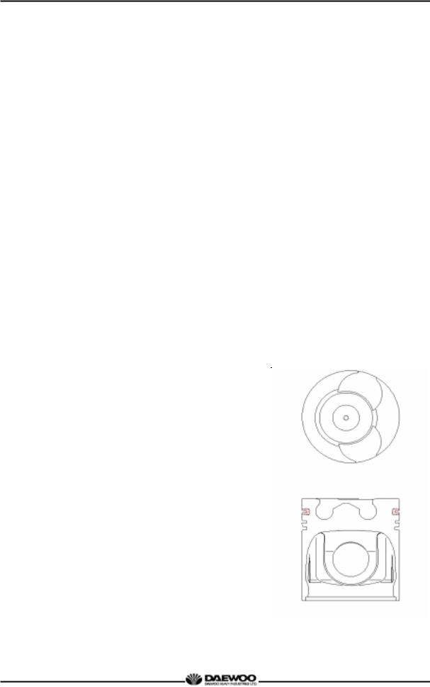
1. GENERAL INFORMATION 1.2.2 OMEGA combustion bowl The OMEGA combustion bowl is a unit designed to perform high efficiency, low emission combustion. As the rim around the combustion bowl port of the upper of the piston has been machined in a smaller size than the interior of the combustion bowl, strong swirl is produced in the combustion bowl and strong squish flow makes the fuel be mixed more sufficiently with air. -
Page 9
1. GENERAL INFORMATION 1.3 Engine Specifications 1.3.1 Specification DE08TIS PBL00 MBE00 4 cycle in-line, water cooled type, Engine type Turbocharged & intercooled Combustion chamber type Direct injection type Cylinder liner type Replaceable dry liner Timing gear system Gear driven type Number of piston rings Compression ring 2, oil ring 1 Number of cylinders — bore x stroke… -
Page 10
1. GENERAL INFORMATION 1.3.2 Engine power Production tolerance : ±5% Engine Model Performance Product Power Torque Low Idle High Idle Remark Model (kgf•m/RPM) Code (PS/RPM) (RPM) (RPM) DE08-PBL00 217.6/2,000 92/1,300 2,200 DE08TIS MBE00 212/1,800 85/1,400 1,000 2,000… -
Page 11
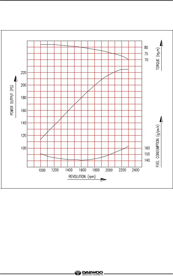
1. GENERAL INFORMATION 1.3.3 Performance curve (DE08TIS — 225PS) Performance ISO 1585 (SAE J1349) Output (max.) 160 kW (217.6 PS) / 2,000 rpm Torque (max.) 902 N.m (92 kg· m) / 1,300 rpm Fuel consumption (min.) 213 g/kW.h (156 g / PS.h) -
Page 12
1. GENERAL INFORMATION 1.3.4 Performance curve (DE08TIS – MBE00 – 195PS) KS – B6537 Performance Output (max.) 143 kW (195 PS) / 1,800 rpm Torque (max.) 833.6 N.m (85 kg.m) / 1,400 rpm Fuel consumption (min.) 214 g/kW.h (158 g / PS.h) -
Page 13
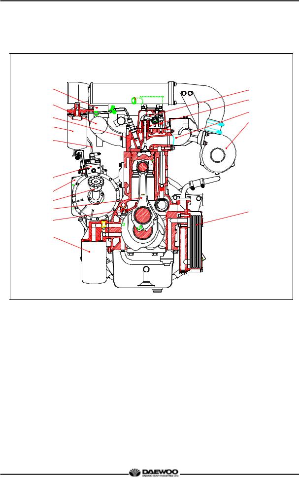
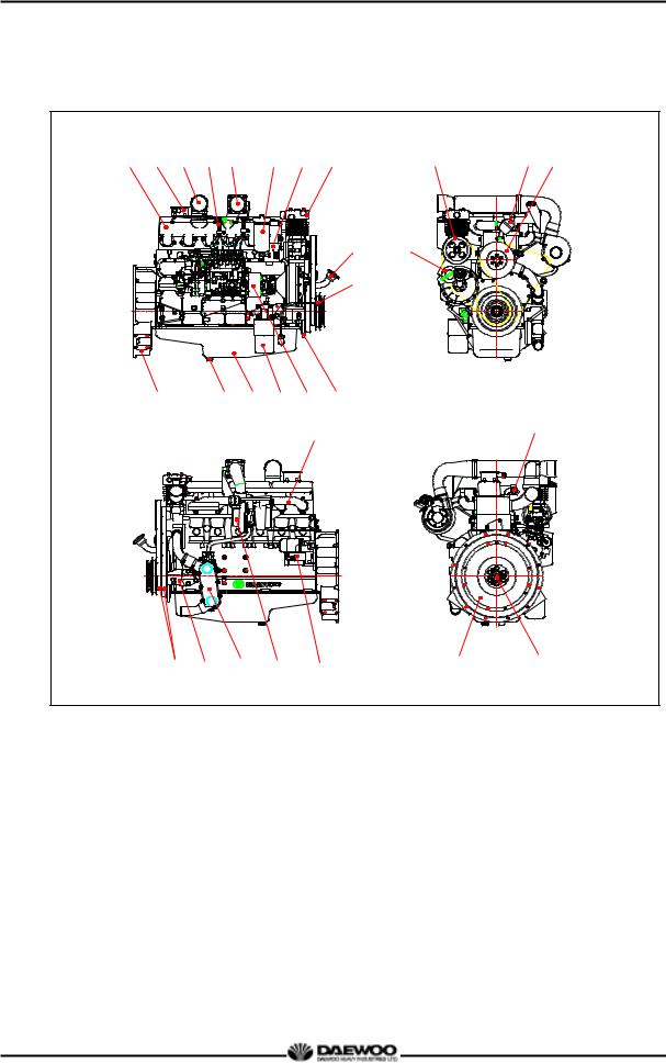
1. GENERAL INFORMATION 1.4 Engine Assembly 1.4.1 Engine sectional view (longitudinal) 1. Water pump 10. Intake valve spring 19. Oil seal (Front) 2. Piston 11. Cylinder block 20. Crank shaft pulley 3. Air compressor 12. Push rod 21. Crank shaft gear 4. -
Page 14
1. GENERAL INFORMATION 1.4.2 Engine sectional view (cross) 1. Fuel injection pipe 9. Turbo charger 2. Fuel filter 10. Fuel injection pump 3. Fuel injection nozzle 11. Timing gear case 4. Intake manifold 12. Oil filler cap 5. Air heater 13. -
Page 15
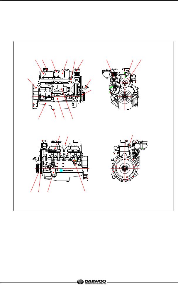
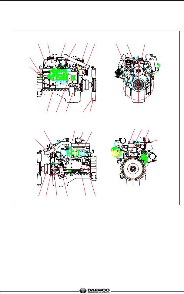
1. GENERAL INFORMATION 1.4.3 Engine assembly views 1. Flywheel housing 10. Turbocharger 19. Breather 2. Fuel filter 11. Exhaust pipe 20. Thermostat 3. Intake pipe 12. Lifting hook (Rear) 21. Water pump 4. Fuel injection pump 13. Starter 22. Crankshaft pulley 5. -
Page 16
·Since DE08TIS diesel engine cylinder liner is dry type, particularly the cooling water control should be applied thoroughly by the cooling water test kit. (DOOSAN 60.99901-0038) ·The density of antifreezing solution and additive for rust prevention is able to be confirmed by the cooling water test kit. -
Page 17
2. MAJOR MAINTENANCE (6) The brown at the middle of test paper and the lower pink color indication represent the additive state for rust prevention, and the proper range is that the meeting numerical value of brown (vertical) and pink color (horizontal) locates in the range of 0.3 to 0.8 at the color list of label on the test paper storage bottle. -
Page 18
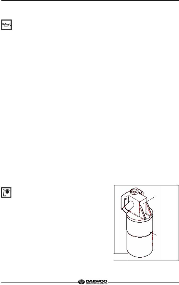
2. MAJOR MAINTENANCE · The following oils are also recommended. Recommend oil Engine model SAE No. API No. SAE 10W40 API CI-4 DE08TIS 2.1.4 Oil filter · Check for oil pressure and oil leaks, and repair or replace the oil filter if necessary. ·Change the oil filter cartridge simultaneously at every replacement of engine oil. -
Page 19
2. MAJOR MAINTENANCE 2.1.7 Intercooler The intercooler is air to air type and has a large cooling fan capacity. The intercooler life and performance depends on the intake air condition greatly. Fouled air pollutes and clogs the air fins of intercooler. As a result of this, the engine output is decreased and engine malfunction is occurred. -
Page 20
2. MAJOR MAINTENANCE (1) Rotate the crankshaft to overlap the intake and the exhaust valves of #6, then #1 cylinder become the compression state of top dead center. (2) Therefore adjust the valve clearance corresponding to “ “of lower figure. At this time there are no force on the push rods of #1 cylinder. -
Page 21
2. MAJOR MAINTENANCE · Install the special tool (compression gauge adapter) at the nozzle holder hole, and connect the compression pressure gauge there. Standard value 28 kg/cm over Standard value 24 kg/cm Difference Within ±10% between each cylinder * Condition: Water temperature 20°C, Engine rotation 200rpm (10 rotations) 2.1.10 Injection nozzle ·… -
Page 22
2. MAJOR MAINTENANCE 2.1.13 Air removal of fuel system The suction room of fuel injection pump has the function of air removal continuously during the operation through a relief valve. In case that the suction room lacks fuel at all, for instance, in case of new installation of injection pump, after loosening the air removing screws of cartridge filter respectively, remove the air by operating the manual pump of fuel supply pump until bubble will disappear. -
Page 23
2. MAJOR MAINTENANCE 2.2 Diagnosis and Remedy ·The following description summarizes the probable cause of and remedy for generall failure by item. ·Immediate countermeasures should be taken before a failure is inflamed if any symptom is detected. -
Page 24
2. MAJOR MAINTENANCE… -
Page 25
2. MAJOR MAINTENANCE… -
Page 26
2. MAJOR MAINTENANCE… -
Page 27
2. MAJOR MAINTENANCE… -
Page 28
2. MAJOR MAINTENANCE… -
Page 29
2. MAJOR MAINTENANCE… -
Page 30
2. MAJOR MAINTENANCE… -
Page 31
2. MAJOR MAINTENANCE… -
Page 32
2. MAJOR MAINTENANCE 2.3 Engine Inspection 2.3.1 Stopping engine After checking the engine for any unusual condition at the idling speed, then turn the key switch to stop the engine. 2.3.2 General engine inspection cycle ○ : Inspection and adjustment ● : Replacement Inspection interval (hours) Check Points Daily… -
Page 33
2. MAJOR MAINTENANCE 2.3.3 Use of original parts for repair and replacement For engine is being mechanically harmonized with many parts, only when the original parts that the manufacture recommends to use is used, the engine trouble would be preventively maintained and capable to keep up the maximum performances. -
Page 34
3. MAINTENANCE 3. MAINTENANCE 3.1 Engine Disassembly 3.1.1 Heed at disassembly ·Before disassembly, the part shelf should be prepared for various tools and repair parts. ·When assembling, clean empty hand should be used and clean environment maintained. ·In case of storing the disassembled parts, each part should not touch each other. ·In case of disassembly, the parts should be laid in order. -
Page 35
3. MAINTENANCE 3.1.4 Engine oil ·Remove the oil drain plug of oil pan and pour the engine oil into the prepared vessel. 3.1.5 Cooling fan ·Remove the flange fixing bolts, then take off the flange and cooling fan. 3.1.6 Belt ·Loosen the tension adjusting bolts of the alternator and the idle pulley, and take off the belts. -
Page 36
3. MAINTENANCE 3.1.8 Starter ·Unscrew the starter fixing nuts and remove the starter being careful not to damage its gears. 3.1.9 Fuel filter ·Remove the hollow screws of filter and tear down fuel supply and discharge rubber hose. ·Remove fuel filter fixing bolts and disassemble the fuel filter. -
Page 37
3. MAINTENANCE 3.1.12 Alternator ·Remove the alternator assembling bolt and disassemble the alternator. 3.1.13 Oil cooler ·Loosen the cooling water pump and the rubber hose clamps of connected pipes, and disassemble it. ·Remove the oil cooler fixing bolts and take off the oil cooler. -
Page 38
3. MAINTENANCE 3.1.16 Air compressor ·Remove the oil pipe between cylinder block and air compressor. ·Unscrew the air compressor fixing bolts and take off the air compressor. 3.1.17 Idle pulley ·Unscrew the idle pulley fixing bolts and take off the idle pulley. -
Page 39
3. MAINTENANCE 3.1.20 Fuel injection nozzle ·Unscrew the fuel injection pipe between the injection pump and nozzle and take off the pipe. ·Install a special jig on the nozzle holder, and then pull out the nozzle as striking the hammer of the jig backwardly. -
Page 40
3. MAINTENANCE 3.1.23 Intake manifold ·Unscrew the intake manifold fixing bolts and remove the intake manfold from the cylinder head. ·Disassemble the intake manifold gasket and discard it. 3.1.24 Cooling water pipe ·Unscrew the cooling water pipe fixing bolts and remove the cooling water pipe from the cylinder head. -
Page 41
3. MAINTENANCE 3.1.26 Cylinder head ·Remove the cylinder head bolts in the reverse order of tightening but remove it step by step. First step : Loosen 1 ~ 2 threads Second step : Remove by loosening fully. ·However, remove the total bolts simultaneously by the step of 1 and 2. -
Page 42
3. MAINTENANCE 3.1.27 Oil pan ·Unscrew the oil pan fixing bolts and remove the oil pan. ·Remove the oil pan gasket and discard it. 3.1.28 Vibration damper ·Unscrew the vibration damper fixing bolts in reverse sequence of installing sequence and remove the vibration damper assembly. -
Page 43
3. MAINTENANCE 3.1.31 Piston and connecting rod ·Remove the connecting rod cap bolts in the reverse order of assembling but do same as the cylinder head bolt removal. ·Disassemble the upper/lower of connecting rod caps by tapping lightly with urethane hammer, and remove the bearing. -
Page 44
3. MAINTENANCE (3) Remove the piston ring with a plier. (4) Clean the piston thoroughly. 3.1.32 Cylinder liner ·Diassemble the cylinder liner with a special tool or hand but be careful not to generate any damage at cylinder block. 3.1.33 Cam shaft gear and idle gear ·Unscrew the camshaft gear fixing bolts and remove the camshaft gear. -
Page 45
3. MAINTENANCE ·Unscrew two bolts fixing the idle gear, then remove the idle gear and its pin. 3.1.34 Fuel injection pump ·Disassembly the oil hose for lubrication. ·Remove the bolts and nuts of injection pump flange. ·Unscrew the injection pump fixing bolts and remove the injection pump by lifting it up. -
Page 46
3. MAINTENANCE 3.1.36 Fly wheel ·Remove the flywheel fixing bolts and disassemble it. · The bolt removal is done by the reverse order of assembling and by the steps. 3.1.37 Fly wheel housing · Remove the flywheel housing fixing bolts and disassemble the flywheel housing. -
Page 47
3. MAINTENANCE 3.1.40 Bearing cap ·Remove the bearing cap assembling bolts by the step in the reverse order of assembling, and disassemble the bearing cap. (Remove by the same way as the cylinder head bolts’ removal.) ·Disassembled bearing caps are kept laid in order. 3.1.41 Crankshaft ·… -
Page 48
3. MAINTENANCE 3.1.43 Oil spray nozzle (D1146TI, DE08TIS only) · Remove the valve screws of oil spray nozzle and disassemble it. -
Page 49
3. MAINTENANCE 3.2 Inspection and Measurement on Major Parts 3.2.1 Cylinder block ·Clean the cylinder block thoroughly, and check for any crack or damage. ·If there is any crack or severe damage, replace it and if there is minor one, correct it. ·Check for any clogging or corrosion in the oil passage and water passage. -
Page 50
3. MAINTENANCE 2) Inspection of cylinder head (1) Check for the cylinder head. ·Remove carbon from the cylinder head lower surface, and then should be careful not to scratch the surface. ·· Check any crack or damage that can not found by naked eyes through the hydraulic or magnetic particle test. -
Page 51
3. MAINTENANCE 3) Inspection of valve and valve guide (1) Valve After cleaning valve with fuel, check it. ·Valve stem outer diameter Measure the valve stem outer diameter at 3 positions (top, middle, and bottom), and check for any wear and if beyond the limit value, replace the valve. -
Page 52
3. MAINTENANCE ·Assemble the valve at cylinder head’s valve guide and see if it is centered with the valve seat using a special tool. 3) Valve seat ·Contacting face amount As for the valve seat’s wear, measure the width of the contact surface with intake valve seat and exhaust valve seat. -
Page 53
3. MAINTENANCE ·For the disassembling of valve seat, by welding the welding bead to a valve seat rotating tool or valve seat, pull it out with a special tool. ·For the assembling of a new valve seat, by putting it among the dry ices of an ice box previously for about 2 hours for the cold shrinkage, and press it in the cylinder head by a special tool. -
Page 54
3. MAINTENANCE ·Valve spring tension Use a spring tester to measure the valve spring tension if the measured value is less than the specified limit, the valve spring must be replaced. 5) Assembling cylinder head ·Clean the cylinder head thoroughly. ·Replace the valve stem seal with new one, and by means of a special tool, press the stem seal into the valve guide of cylinder head. -
Page 55
3. MAINTENANCE 2) Inspection of rocker arm assembly (1) Rocker arm shaft ·Rocker arm shaft run-out Place the rocker arm shaft on two V blocks and inspect the shaft for bend using a dial gauge. If the amount of this run-out is small, press the shaft with a bench press to correct the run-out Replace the shaft if the measured value exceeds the limit. -
Page 56
3. MAINTENANCE (3) Tappet and push rod ·Clearance Measure the clearance of the tappet and tappet holes of the cylinder block. If the value is beyond the specified limit, replace tappets. Standard Limit 0 .035 ~ 0 .07 7 m m 0 .15 m m ·Visual check of tappet Visually check the face of the tappets in contact with… -
Page 57
3. MAINTENANCE ·Be careful not to occur any swap of position and reverse assembly. 3.2.4 Camshaft 1) Camshaft end play ·Push the thrust plate toward the cam gear ·With a feeler gauge, measure the clearance between the thrust plate and camshaft journal. ·If the end play is excessive, replace the thrust plate. -
Page 58
3. MAINTENANCE 3) Cam shaft · Clearance between camshaft journal and camshaft bush With an outside micrometer, measure the camshaft journal diameter. Measure the inside diameter of the camshaft bushing on the cylinder block using a cylinder bore indicator, and compare the measured value with the camshaft outside diameter to determine the clearance. -
Page 59
3. MAINTENANCE ·If the amount of wear is beyond the limit, have the crankshaft ground and install undersize bearings. However, if the amount of wear is within the limit, you can correct the wear using an oil stone or oiled grinding paper of fine grain size. -
Page 60
3. MAINTENANCE 2) Crankshaft bearing and connecting rod (1) Visual check ·Visually check the crankshaft bearing and connecting rod bearing for scores, uneven wear or damage. (2) Oil clearance between crankshaft and bearing (Method 1: dial gauge) ·Main bearing clearance Install the main bearing in the cylinder block, tighten the bearing cap to specified torque, then measure the inside diameter. -
Page 61
3. MAINTENANCE (3) Oil clearance between crankshaft and bearing (Method 2: plastic gauge) ·Assemble the crankshaft on the cylinder block and put plastic gauge on the journal and pin of crankshaft and then after assembling bearing cap, tighten the bolts at the specific torque. -
Page 62
3. MAINTENANCE ·Connecting rod bearing crush Install the bearing and cap in the connecting rod big end, retighten the bolts to specified torque, unscrew out one bolt completely, then measure the clearance between the bearing cap and connecting rod big end using a feeler gauge. -
Page 63
3. MAINTENANCE 3.2.6 Piston assembly 1) Disassemby of piston assembly Disassemble piston according to the disassembly process. 2) Piston inspection (1) Visual check Visually check the pistons for cracks, scuff or wear, paying particular attention to the ring groove. (2) Clearance between the piston and cylinder liner ·With an outside micrometer, measure the piston outside diameter at a point 13mm away from the lower end of piston skirt in a direction at a right… -
Page 64
3. MAINTENANCE 3) Piston rings (1) Visual check Replace the piston rings with new ones if detected worn or broken when the engine is overhauled. (2) Piston ring gap ·Insert the piston ring into the upper portion of the cylinder liner bore so that it is held at a right angle to the cylinder liner wall. -
Page 65
3. MAINTENANCE 4) Piston pin inspection (1) Wear Measure the amount of wear on the piston pin at the points as shown. The measured values are beyond the limit (0.08 mm or greater), replace the pin. (2) Clearance Measure the clearance between the piston pin and connecting rod bushing, and replace either of them, whichever damaged more, if the measured value is beyond the limit. -
Page 66
3. MAINTENANCE (2) Holes alignment (parallelism) Measure the alignment of the connecting rod piston pin bushing holes with connecting rod big end holes. At this time also, use both connecting rod tester and feeler gauge. (3) Wear ·Assemble the connecting rod to the crankshaft and measure connecting rod big end side clearance using a feeler gauge. -
Page 67
3. MAINTENANCE 3.3 Engine Reassembly 3.3.1 General precautions ·Clean all the disassembled parts, particularly oil and water ports, using compressed air, then check that they are free from restrictions. ·Arrange the general and special tools in order for engine assembly operation. ·To wet each sliding part, prepare the clean engine oil. -
Page 68
3. MAINTENANCE ·Apply engine oil to the entire face of the tappets and slide them into the tappet holes on the cylinder block. ·Wet the cam bush inside diameter and camshaft with oil, and carefully assemble them while turning the camshaft. -
Page 69
3. MAINTENANCE ·Heat the crankshaft gear for at least 10 minutes to 120°C, then apply sealant (Loctite # 641) to the inside wall of the heated crankshaft gear evenly before inserting it to the end of crankshaft. ·Semi-tighten a bolt at both sides of the crankshaft, apply engine oil to journals and pins, then assemble the crankshaft with the cylinder block by tightening the fixing bolts. -
Page 70
3. MAINTENANCE ·Install the bearing cap by matching the cylinder block No. with the bearing cap No. ·Apply oil to the entire part of the bearing cap bolts, then tighten in tightening sequence to specified torque. ·After semi-tightening both bolts evenly, tighten them diagonally to the specified torque using a torque wrench as follows. -
Page 71
3. MAINTENANCE ·The flywheel housing is assembled after the new oil seal was pressed (Coat engine oil over the outside of oil seal) before in the housing by a press. ·If any peripheral scar was generated due to oil seal at the oil seal contact surface of crankshaft, after inserting about 1 mm shim or thereabout in front of oil seal (Direction toward crankshaft.), measure and… -
Page 72
3. MAINTENANCE ·Install a guide bar into a bolt hole on the crank shaft, and lift the flywheel to align the dowel pin with the pin hole on the flywheel for temporary assembly operation. ·Coat the adhesive (#271 Loctite) over the assembling bolts and install bolts in the remaining holes. -
Page 73
3. MAINTENANCE 3.3.10 Water chamber cover · Coat the adhesive over the water chamber cover (Particular around bolt holes) and after attaching the gasket, assemble it to the cylinder block using the bolts for assembling. ·As for tightening of bolts, after primarily tightening the bolts located at the both ends of cover (4ea at both sides) and middle bolts (Upper, lower 2ea) , tighten the rest. -
Page 74
3. MAINTENANCE ·Nothing the direction of the piston, make the longer side(machined with key groove on the bearing) of the connecting rod big end. · On the piston head surface, the longer side connecting rod big end is in opposite direction from the valve seating surface as well as in the same direction with the narrow margin of the combustion chamber. -
Page 75
3. MAINTENANCE ·Position the valve seating surface toward the tappet hole and insert the piston with hand. Caution: Use care not to damage the cylinder liner and piston, and slightly lift and insert the piston into the cylinder so that the ring may not be damaged by the fillet of the liner. -
Page 76
3. MAINTENANCE · When the connecting rod bearing cap bolts are tightened, check the connecting rod end play to the right and left with hand. If no end play is found, remove and reinstall or replace the connecting rod bearing cap. 3.3.13 Timing gear case ·Mount a new gasket using dowel pin on the cylinder block. -
Page 77
3. MAINTENANCE ·With the oil port on the idle gear pin facing the cylinder block, install the idle gear pin. · Idler gear pin with oil hole is assembled toward cylinder block. ·Install the idle gear by coinciding the marks impressed on the crank gear, cam gear, fuel injection pump drive gear, and idle gear. -
Page 78
3. MAINTENANCE 3.3.16 Fuel injection pump ·Install the injection pump bracket in the cylinder block. · After measuring the amount of run-out with an alignment setting jig, disassemble the bracket, adjust the shims, then reassemble it. ·Mount the top/bottom adjusting shims in the bracket and then mount the fuel injection pump. -
Page 79
3. MAINTENANCE (1) As above adjusting method, Please coincide the indication point at the flywheel housing’s inspection hole with the flywheel’s inspection angle. (2) Loosen the drive gear fixing bolt of injection pump a bit. (3) After turning slowly the coupling of injection pump until the fuel will drop from #1 plunger at the rate of a drop for 6 ~ 8 sec., tighten the driving gear fixing bolt of fuel pump. -
Page 80
3. MAINTENANCE 3.3.17 Oil pump and oil pipe · Install a dowel pin in the No.7 bearing cap, then assemble the oil pump by tapping lightly with urethane hammer. ·Tighten the assembling bolts with specified torque. ·Assemble the oil suction pipe with the delivery pipe to oil pump by the bolts. -
Page 81
3. MAINTENANCE 3.3.20 Water pump ·Mount a new gasket. · Install the water pump on the cylinder block and tighten the assembling bolts with specified torque. ·Connect water pipes and by-pass pipe to the water pump. ·Connect a water pipe to the expansion tank. 3.3.21 Vibration damper ·… -
Page 82
3. MAINTENANCE · Assemble the oil pan by tightening the oil pan assembling bolts, and when tightening bolts, primarily tighten the bolts (4ea) at the both ends, and then tighten the rest bolts to specified torque. Caution: Align the bolt holes with gasket holes to prevent damage to the gasket and tighten. -
Page 83
3. MAINTENANCE 3.3.26 Intake and exhaust valves ·Identify the marks of “IN” and “EX” impressed on the valve head before assembling the valve with the valve head. ·With a valve stem seal fitting jig, assemble the valve stem seal on the valve guide. ·After installing valve springs and spring retainer, press the retainer with a jig, then install the cotter pin. -
Page 84
3. MAINTENANCE ·Check the inside of combustion chamber for foreign substances, and carefully mount the cylinder head assembly in the block by aligning the dowel pin with the dowel pin hole. Caution: Be careful not to damage the cylinder head gasket. If the dowel pin is not in alignment, lift the cylinder head again and then remount it. -
Page 85
3. MAINTENANCE 3.3.28 Rocker arm assembly ·Apply lubricating oil to the rocker arm bush and shaft, and assemble the intermediate bracket with the rockerarm (rocker arm assembly) on the cylinder block using fixing bolts. In tightening the bolts, it must be done at the specified value using zigzag method. -
Page 86
3. MAINTENANCE ·To adjust the clearance, loosen the locknuts of rocker arm adjusting screws and push the feeler gauge of specified value between a rocker arm and a valve stem (to measure the clearance of the valve and rocker arm contacting part) and adjust the clearance with adjusting screw respectively and then tighten with the lock nut. -
Page 87
3. MAINTENANCE 3.3.30 Exhaust manifold ·Install the exhaust manifold gasket over the stud bolts by aligning the gasket with the exhaust port on the cylinder head so that the face and back of the gasket can be positioned correctly. ·Semi-assemble the exhaust manifold and install the heat resisting plate. -
Page 88
3. MAINTENANCE 3.3.33 Idle pulley ·Assemble the air compressor mounting bracket on the timing gear case. ·Install the idle pulley on the air compressor mounting bracket and tightening the fixing bolt. 3.3.34 Air compressor & power steering pump · Couple the power steering oil pump to the air compressor with the driving dog engaged. -
Page 89
3. MAINTENANCE 3.3.36 Fuel filter ·Assemble the fuel filter with the intake manifold. ·Assemble the fuel feed hose according to the direction of an arrow impressed on the fuel filter head so that fuel can be fed in the sequence of FUEL FEED PUMP FUEL FILTER FUEL INJECTION PUMP. -
Page 90
3. MAINTENANCE 3.3.39 Cylinder head cover ·Attach a new gasket on the cylinder head cover. ·Assemble the cylinder head cover to the cylinder head by tightening the cap bolts for fixing the cylinder head cover. Torque 3.1 kg· m ·Assemble the breather and breather hose. ·Fit the oil filler cap on the cylinder head cover. -
Page 91
3. MAINTENANCE 3.3.42 Oil level gauge ·Apply sealant (Locktite #262) to the bottom side of the guide tube. ·Then assemble the guide tube and oil level gauge on the oil pan. 3.3.43 Others ·Assemble by connecting the other oil and fuel hoses. -
Page 92
3. MAINTENANCE 3.4 BREAKING IN 3.4.1 Preparations for breaking-in Fill of new engine oil through the oil filler cap. ·When measuring the oil level with the oil level gauge with the engine mounted, the oil level must indicate about 10mm above the max. line. ·Connect water hoses and fill up cooling water. -
Page 93
3. MAINTENANCE c) Watch the engine water temperature gauge and be sure there is proper water circulation. The water temperature gauge needle will fluctuate if water level in expansion tank is too low. At the end of the break-in period, remove break-in oil and replace the oil filter. Fill oil pan with recommended engine oil. -
Page 94
4. MAINTENANCE OF MAJOR COMPONENTS 4. MAINTENANCE OF MAJOR COMPONENTS 4.1 Cooling System 4.1.1 General information This engine is water-cooling type. Heat from the combustion chamber and engine oil heat are cooled down by coolant and radiated to the outside, resulting in the normal operation of the engine. The water absorbing the oil heat and combustion chamber heat goes on to the thermostat through the water pipe, and circulates to the water pump if water temperature is lower than the valve opening temperature on the thermostat, while circulating to the radiator at water temperature higher than the valve… -
Page 95
4. MAINTENANCEOF MAJOR COMPONENTS 4.1.3 Thermostat ·General descriptions and main data The thermostat maintains a constant temperature of coolant and improves thermal efficiency of the engine by preventing heat loss. Namely, when the temperature of coolant is low, the thermostat valve is closed to make the coolant bypass to directly enter the water pump;… -
Page 96
4. MAINTENANCE OF MAJOR COMPONENTS ·Replacing thermostat and precautions for handling (1) Precautions for handling The wax pallet type thermostat does not react as quickly as bellows type one to a variation of temperature of coolant. Such relatively slow reaction is mainly due to the large heat capacity of the wax pellet type thermostat. -
Page 97
4. MAINTENANCEOF MAJOR COMPONENTS 4.1.4 Diagnostics and troubleshooting… -
Page 98
4. MAINTENANCE OF MAJOR COMPONENTS 4.2 Lubricating System 4.2.1 General descriptions and specifications ·General descriptions All the engine oil pumped up from the oil pan by the gear type oil pump is filtrated through the oil cooler and oil filter, and this filtrated oil is forced through the main oil gallery in the cylinder block from where it is distributed to lubricate the various sliding parts, and fuel injection pump in order to ensure normal engine performance. -
Page 99
4. MAINTENANCEOF MAJOR COMPONENTS 4.2.2 Oil pump ·Disassembly (1) Disassembly of oil pump drive gear a. Unscrew the screw and disassemble the oil relief valve. b. Unfold the washer for the oil pump drive gear fixing nut and remove the nut. c. -
Page 100
4. MAINTENANCE OF MAJOR COMPONENTS (3) Measuring clearance between drive shaft and bushing a. Measure the outside diameters of the drive shaft and driven shaft, and replace if the measured values are less than the limit (N16.95mm) b. Measure the inside diameter of the pump body bushing to determine the clearance between the bushing and shaft, and compare the measured value with the standard value to determine whether to replace or not. -
Page 101
4. MAINTENANCEOF MAJOR COMPONENTS 4.3 Fuel Injection Pump 4.3.1 General information of fuel system The fuel system consists of the fuel tank, injection pump, injection nozzle, fuel filter, and fuel lines such as pipes and hoses necessary to connect those components. 4.3.2 Injection pump The components relating to the injection pump should be serviced at regular intervals as the plunger and delivery valve may be worn after a given length of time for use and cause the deterioration of the engine. -
Page 102
4. MAINTENANCE OF MAJOR COMPONENTS 1) DE08TIS (225PS) -
Page 103
4. MAINTENANCEOF MAJOR COMPONENTS (7) Governor adjustment (DE08TIS-225PS) -
Page 104
4. MAINTENANCE OF MAJOR COMPONENTS 2) DE08TIS (240PS) -
Page 105
4. MAINTENANCEOF MAJOR COMPONENTS (7) Governor adjustment (DE08TIS-240PS) -
Page 106
4. MAINTENANCE OF MAJOR COMPONENTS 4.3.4 Fuel feed pump 1) General descriptions and construction The P-type injection pump is mounted with K-ADS or KP type feed pump. These pumps have the same basic construction and operation, and the general descriptions of the KP type pump are given below: The figures show its construction (right figure) and operation (below figure). -
Page 107
4. MAINTENANCEOF MAJOR COMPONENTS This feed pump is mounted with a priming pump designed to permit manual feeding of fuel from the fuel tank with the injection pump mounted in the engine. During the manual feeding operation, air must be bled from the fuel lines. -
Page 108
4. MAINTENANCE OF MAJOR COMPONENTS 2) Disassembly ·Clamp the feed pump with a vise and disassemble the hollow screw (30, 32), strainer (31) and seal ring (35, 36). ·Take off the priming pump (25), plug (16), both seal rings (18), spring (15), and check valve (14). ·Take off the plug (7), seal ring (8), spring (6), and piston (5) on the piston side. -
Page 109
4. MAINTENANCEOF MAJOR COMPONENTS 5) Testing (1) Suction capacity test Connect one end of a hose to the inlet side of the feed pump and immerse the other end of it into the fuel tank as illustrated. Hold the feed pump in position about 1 m above the level of fuel in the fuel tank. -
Page 110
4. MAINTENANCE OF MAJOR COMPONENTS 4.3.5 Injection nozzle 1) General descriptions Pressurized fuel delivered from the fuel injection pump is sprayed into the combustion chamber past the injection nozzle at proper spray pressure and spray angle, then burnt completely to achieve effective engine performance. -
Page 111
4. MAINTENANCEOF MAJOR COMPONENTS 6) Adjustment ·After reassembly, install the nozzle on a tester. ·With the adjusting screw loosened, operate the nozzle 2 ~ 3 times to bleed it. ·Operate the nozzle tester lever at the specified rate. ·Adjust the injection pressure to the standard pressure by spring tension shims. -
Page 112
4. MAINTENANCE OF MAJOR COMPONENTS 4.3.6 Diagnostics and troubleshooting… -
Page 113
4. MAINTENANCEOF MAJOR COMPONENTS… -
Page 114
4. MAINTENANCE OF MAJOR COMPONENTS 4.4 Turbocharger (D1146TI, DE08TIS) 4.4.1 Main data and specifications 1) Main data and specifications 2) Construction… -
Page 115
4. MAINTENANCEOF MAJOR COMPONENTS 3) Operating principle The turbocharger is a system designed to make use of the engine exhaust gas energy to charge high- density air into the cylinders, thereby to increase the engine output. 4.4.2 General descriptions The engine output is determined by the fuel delivery volume and engine efficiency. To burn the supplied fuel completely to change into effective power for the engine, the volume of air enough to burn the fuel completely should be supplied into the cylinders. -
Page 116
4. MAINTENANCE OF MAJOR COMPONENTS 4.4.3 Functions 1) Turbine Exhaust gas discharged from the combustion chamber distributes its own energy to the turbine blades while passing the inside of the turbine housing, with the result that the turbine shaft can get rotating force. -
Page 117
4. MAINTENANCEOF MAJOR COMPONENTS 4.4.4 Precautions for operation 1) Precautions for operation of engine The following precautions should be observed when starting, operating, or stopping the engine:… -
Page 118
4. MAINTENANCE OF MAJOR COMPONENTS 4.4.5 Walk-around check and servicing As the condition of turbocharger depends greatly on how well the engine is serviced, it is very important to maintain the engine in accordance with the specified maintenance procedure. 1) Intake system Pay particular attention to the air cleaner when servicing the intake system. -
Page 119
4. MAINTENANCEOF MAJOR COMPONENTS 4.4.6 Periodical checking and servicing Make it a rule to check the turbocharger assembly for condition and contamination periodically. 1) Guide for checking the rotor for rotating condition The inspection of the rotor assembly for rotating condition should be performed by the degree of unusual sound. -
Page 120
4. MAINTENANCE OF MAJOR COMPONENTS (3) If the measured axial and radial plays are beyond the limit of wear, replace or repair the turbocharger. 3) Guide for disassembling/cleaning and checking the turbocharger First, disassemble the turbocharger from the engine and clean/check it with the oil inlet and outlet plugged with tape and so on. -
Page 121
4. MAINTENANCEOF MAJOR COMPONENTS 4.4.7. Diagnostics and troubleshooting… -
Page 122
APPENDIX APPENDIX ·Tightening torque for major parts 1st : 6 kg m 2nd : 90 3rd : 90 4th : 90 5th : 60 (Angle method) ·Tightening torque for fuel injection pump system… -
Page 123
3. Special screws should be tightened to 85% or so of the standard value. For example, a screw coated with MoS2 should be tightened to 60% or so of the standard value. ·Tightening torque for hollow screw (4-hole) *: Adopted in DOOSAN engine… -
Page 124
APPENDIX ·Maintenance specification table… -
Page 125
APPENDIX… -
Page 126
APPENDIX… -
Page 127
APPENDIX… -
Page 128
APPENDIX… -
Page 129
APPENDIX… -
Page 130
APPENDIX… -
Page 131
APPENDIX… -
Page 133
950106-080006 Special Tool List… -
Page 134
Special Tool List Engine Model Part Number Figure Part Name FR Oil Seal Assembly Jig ● ● 860104-02047 RR Oil Seal Assembly Jig ● ● 860104-04026 Dust Cover ● ● 860104-04070 RR Oil Seal Holder ● 860104-05075 RR Oil Seal Guide ●… -
Page 135
Engine Model Part Number Figure Part Name Valve Stem Seal ● ● ● 860104-06509 FR Oil Seal Assembly Ass’y ● 860104-05435 RR Oil Seal Assembly Ass’y ● 860104-05436 Valve Stem Seal ● 860104-03876 RR Wearing Insert ● 860104-03875 CYL Liner Disassembly ●… -
Page 136
Engine Model Part Number Figure Part Name FR Oil Seal Assembly Ass’y ● 860104-05438 RR Oil Seal Assembly Ass’y ● 860104-05437 Valve Stem Seal ● 860104-06347 RR Wearing Insert ● 860104-03871 FR Wearing Insert ● 860104-03872 HP Pump Idle Gear ●… -
Page 137
Engine Model Part Number Figure Part Name Oil Spray Nozzle Assembly ● 860104-03892 FR Oil Seal Holder ● 860104-02918 FR Oil Seal Guide ● 860104-02919 Valve Stem Seal ● ● 860104-03881 Valve Spring Jig ● 860104-03921 Valve Stem Seal ● 860104-03880 Compression Adapter… -
Page 138
Engine Model Part Number Figure Part Name FR Oil Seal Assembly Ass’y ● ● 860104-06469 Valve Spring Jig ● ● 860104-03391 RR Oil Seal Assembly Jig ● 860104-06471 RR Oil Seal Disassembly ● Ass’y 860104-03923 Nozzle Tube Assembly Jig ● 860104-01429 Nozzle Tube Disassembly Jig… -
Page 139
Engine Model Part Number Figure Part Name Wearing Insert ● ● 860104-00885 Wearing Insert ● ● 860104-03874 Valve Stem Seal ● 860104-03877 Valve Spring Jig ● 860104-03920 CYL Liner Disassembly ● 860104-03883 Compression Adapter ● 860104-03885 Valve Spring Jig ● ● ● ● ● ● ● ● ● ● ● ● 860104-03391 — 6 -… -
Page 140
Engine Model Part Number Figure Part Name Valve Stem Seal ● 860104-03878 Compression Adapter ● 860104-03888 INJ Pump Fix Jig ● 860104-00261 Camshaft Assembly Guide ● 860104-03893 Wearing Insert ● 860104-03873 Flywheel O-ring Assembly Jig ● 860104-03628 FR Oil Seal Assembly Jig ●… -
Page 141
Engine Model Part Number Figure Part Name Compression Adapter ● 860104-03884 Piston Ring Assembly Jig 850322-00177 Injector Assembly ● 860104-01908 HP Connector ● EF.120-277 CYL Liner Disassembly ● EF.123-365 FWH Guide Pin ● 860104-04369 FR Oil Seal Assembly Jig ● 860104-06261 — 8 -… -
Page 142
Engine Model Part Number Figure Part Name RR Oil Seal Guide 860104-06293 ● RR Oil Seal Holder 860104-04878 Valve Stem Seal ● 860104-06375 Nozzle Tube Assembly Tool ● ● ● ● 860103-01548 Piston Sleeve Jig ● ● ● ● ● ● ● ● ● 860104-01296 Injector Assembly ●… -
Page 143
Engine Model Part Number Figure Part Name Compression Pressure Adaptor ● 860104-07064 — 10 -…
 Loading…
![]()
65.99897-8056 Feb. 2001
MAINTENANCE MANUAL
Diesel Engine
D1146
D1146TI
DE08TIS
PS-MMA0415-E1A
D1146/D1146TI/DE08TIS
MAINTENANCE MANUAL
FOREWORD
This maintenance manual is designed to serve as a reference for DAEWOO Heavy Industries Ltd’s (here after DAEWOO’s) customers and distributors who wish to gain basic product knowledge on DAEWOO’s D1146, D1146TI and DE08TIS Diesel engine.
This economical and high-performance diesel engine (6 cylinders, 4 strokes, in-line, direct injection type) has been so designed and manufactured to be used for the overland transport or industrial purpose. That meets all the requirements such as low noise, fuel economy, high engine speed, and durability.
To maintain the engine in optimum condition and retain maximum performance for a long time, CORRECT OPERATION and PROPER MAINTENANCE are essential.
In this manual, the following symbols are used to indicate the type of service operations to be performed.
|
Removal |
Adjustment |
|
Installation |
Cleaning |
|
Disassembly |
Pay close attention-Important |
|
Reassembly |
Tighten to specified torque |
|
Align the marks |
Use special tools of manufacturer’s |
|
Directional Indication |
Lubricate with oil |
|
Inspection |
Lubricate with grease |
|
Measurement |
During engine maintenance, please observe following instructions to prevent environmental damage;
zTake old oil to an old oil disposal point only.
zEnsure without fail that oil and diesel fuel will not get into the sea or rivers and canals or the ground.
zTreat undiluted anti-corrosion agents, antifreeze agents, filter element and cartridges as special waste.
Printed in Jan. 2001 PS-MMA0415-E1A

D1146/D1146TI/DE08TIS
MAINTENANCE MANUAL
zThe regulations of the relevant local authorities are to be observed for the disposal of spent coolants and special waste.
If you have any question or recommendation in connection with this manual, please do not hesitate to contact our head office, dealers or authorized service shops near by your location for any services.
For the last, the content of this maintenance instruction may be changed without notice for some quality improvement. Thank you.
DAEWOO Heavy Industries & Machinery LTD.
Feb. 2001
Printed in Jan. 2001 PS-MMA0415-E1A

D1146/D1146TI/DE08TIS
MAINTENANCE MANUAL
|
CONTENTS |
|
|
1. GENERAL INFORMATION |
|
|
1.1 General Repair Instructions |
1 |
|
1.2. Engine Specific Character |
2 |
|
1.3. Engine Specifications |
4 |
|
1.4. Engine Assembly |
8 |
|
2. MAJOR MAINTENANCE |
|
|
2.1. Preventive Maintenance |
13 |
|
2.2. Diagnosis and Remedy |
22 |
|
2.3. Engine Inspection |
32 |
|
3. MAINTENANCE |
|
|
3.1. Engine Disassembly |
33 |
|
3.2. Inspection and Measurement on Major Parts |
48 |
|
3.3. Reassembly |
69 |
|
3.4. Breaking in |
96 |
|
4. MAINTENANCE OF MAJOR COMPONENTS |
|
|
4.1. Cooling System |
98 |
|
4.2. Lubrication System |
102 |
|
4.3. Fuel Injection Pump |
106 |
|
4.4. Turbocharger |
122 |
|
5. Special Tool List |
132 |
|
● Appendix |
134 |
|
● WORLDWIDE NETWORK |
Printed in Jan. 2001 PS-MMA0415-E1A

D1146/D1146TI/DE08TIS
MAINTENANCE MANUAL
1. GENERAL INFORMATION
1.1.General Repair Instructions
1.Before performing service operation, disconnect the grounding cable from the battery for reducing the chance of cable damage and burning due to short-circuiting.
2.Use covers for preventing the components from damage or pollution.
3.Engine oil and anti-freeze solution must be handled with reasonable care as they cause paint damage.
4.The use of proper tools and special tools where specified is important to efficient and reliable service operation.
5.Use genuine DAEWOO parts necessarily.
6.Used cotter pins, gaskets, O-rings, oil seals, lock washer and self-lock nuts should be discarded and new ones should be prepared for installation as normal function of the parts can not be maintained if these parts are reused.
7.To facilitate proper and smooth reassemble operation, keep disassembled parts neatly in groups. Keeping fixing bolts and nut separate is very important as they vary in hardness and design depending on position of installation.
8.Clean the parts before inspection or reassembly. Also clean oil ports, etc. using compressed air to make certain they are free from restrictions.
9.Lubricate rotating and sliding faces of parts with oil or grease before installation.
10.When necessary, use a sealer on gaskets to prevent leakage.
11.Carefully observe all specifications for bolts and nuts torques.
12.When service operation is completed, make a final check to be sure service has been done property.
1
Printed in Jan. 2001 PS-MMA0415-E1A
D1146/D1146TI/DE08TIS
MAINTENANCE MANUAL
1.2. Engine Specific Character
1.2.1.Toroidal combustion mode (D1146)
The D1146 engine is operated in the toroidal combustion mode that was developed by this company with AVL Co. Australia.
The feature of this mode in the fundamental structure is that there are combustion chambers in the centers of piston heads and swirling passages in the cylinder heads. This swirling passages when intake stroke generates the strong swirling motion in the combustion chambers by giving the intake air a big moment, and when compression stroke, the special piston’s shapes causing very complicated and distorted flows by means of eddy current and squashed flows will make the air and fuel mix more smoothly.
Also, when explosion stroke, a considerable output increase came to be expected with the accomplishment of nearly perfect combustion by the more smooth mixing of air and fuel which was injected through multi-nozzles in the combustion chamber.
This engine by means of Toroidal Combustion Mode has the specific character such as quiet and stable revolutional motion, multi-purpose application, economical fuel and oil consumption, etc.
1.2.2.OMEGA combustion bowl (D1146TI, DE08TIS)
|
The OMEGA combustion bowl is a unit designed |
M1041A |
|
|
to perform high efficiency, low emission |
||
|
combustion. As the rim around the combustion |
||
|
bowl port of the upper of the piston has been |
||
|
machined in a smaller size than the interior of the |
||
|
combustion bowl, strong swirl is produced in the |
||
|
combustion bowl and strong squish flow makes |
||
|
the fuel be mixed more sufficiently with air. |
||
|
Due to the application of OMEGA combustion |
||
|
system and optimal utilization of intake and |
||
|
exhaust port configuration within the cylinder |
||
|
head, the D1146TI, DE08TIS diesel engines |
||
|
discharge very low level of hazardous exhaust |
||
|
gases such as smoke, nitrogen oxide, |
||
|
hydrocarbon, or carbon monoxide and thus |
||
|
ensure high performance and low fuel |
||
|
consumption. |
||
|
2 |
Printed in Jan. 2001 PS-MMA0415-E1A
D1146/D1146TI/DE08TIS
MAINTENANCE MANUAL
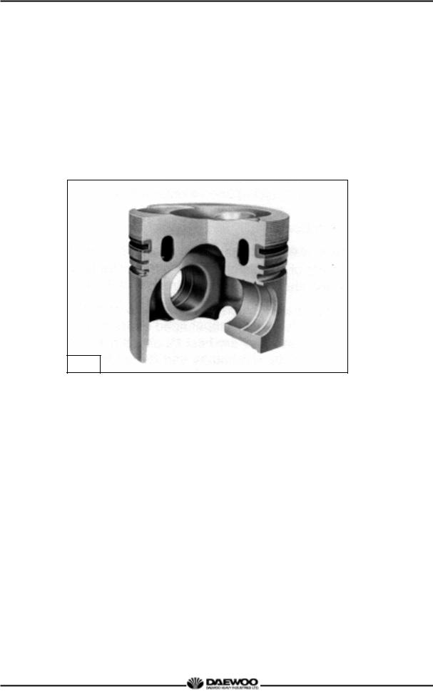
1.2.3.Oil gallery cooling type piston (DE08TIS)
Oil gallery cooling is used for the piston of DE08TIS diesel engine.
When thermal loading is high, piston cooling by means of an oil gallery in the crown is normally necessary to prevent crown cracking and ring sticking. The design of the gallery, the design and location of the oil spray nozzle and the quantity of oil flowing in the gallery are critical in order to achieve the desired temperature reduction.
The cross section shape of the gallery should be designed to achieve sufficient oil movement to maximize cooling efficiency.
M1255
3
Printed in Jan. 2001 PS-MMA0415-E1A

D1146/D1146TI/DE08TIS
MAINTENANCE MANUAL
1.3. Engine Specifications
1.3.1. Specification
|
Engine Model |
D1146 |
D1146TI |
DE08TIS |
|||||
|
Items |
||||||||
|
Engine type |
4 cycle in-line, |
4 cycle |
in-line, |
|||||
|
Water-cooled type |
Water-cooled type |
|||||||
|
Naturally aspirated |
Turbo charged & intercooled |
|||||||
|
Combustion chamber type |
Direct injection type |
|||||||
|
Cylinder liner type |
Replaceable dry liner |
|||||||
|
Timing gear system |
Gear driven type |
|||||||
|
No. of piston ring |
Compression ring 2, oil ring 1 |
|||||||
|
No. of cylinder-bore x stroke |
(mm) |
6 – 111 × 139 |
||||||
|
Total piston displacement |
(cc) |
8,071 |
||||||
|
Compression ratio |
17.5 : 1 |
16.8 : 1 |
18.5 : 1 |
|||||
|
Engine dimension (length x width x height) |
(mm) |
1,253×811.5×934.5 |
1,253×812.5×1,009 |
1,253×812.5×1,009 |
||||
|
Engine weight |
(kg) |
730 |
745 |
745 |
||||
|
Rotating direction (viewed from flywheel) |
Counter clockwise |
|||||||
|
Fuel injection order |
1 – 5 – 3 – 6 – 2 – 4 |
|||||||
|
Fuel injection timing (B.T.D.C static) |
15° |
9° |
3° |
|||||
|
Injection pump type |
Zexel in-line “AD” type |
Zexel in-line “P” type |
||||||
|
Governor type |
Mechanical governor |
Mechanical |
||||||
|
governor |
||||||||
|
type(RLD) |
||||||||
|
type(RLD-J) |
||||||||
|
Injection nozzle type |
Multi-hole type (5 hole) |
Multi-hole type |
||||||
|
(7 hole) |
||||||||
|
Fuel injection pressure |
(kg/cm2) |
210 |
214 |
160/220 |
||||
|
Compression pressure |
(kg/cm2) |
28 (at 200 rpm) |
||||||
|
Intake and exhaust valve clearance (at cold) (mm) |
0.3 |
|||||||
|
Intake valve |
Open at |
16° (B.T.D.C) |
||||||
|
Close at |
36° (A.B.D.C) |
|||||||
|
Exhaust valve |
Open at |
46° (B.B.D.C) |
||||||
|
Close at |
14° (A.T.D.C) |
|||||||
|
Lubrication method |
Full forced pressure feed type |
|||||||
|
Oil pump type |
Gear type driven by crankshaft |
|||||||
|
Oil filter type |
Paper element type |
Cartridge type |
||||||
|
Lubricating oil capacity (max./min.) |
(lit) |
15.5/12 or 20/17 |
||||||
|
Oil cooler type |
Water cooled |
|||||||
|
Water pump |
Centrifugal type driven by belt |
|||||||
|
Cooling Method |
Fresh water forced circulation |
|||||||
|
Cooling water capacity (engine only) |
(lit) |
14 |
||||||
|
Thermostat type |
Wax pallet type |
|||||||
|
(79 94 °C or 83 95 °C ) |
||||||||
|
Air compressor type & capacity |
(cc) |
Belt driven type, 220 or 300 |
||||||
|
Alternator voltage – capacity |
(V – A) |
24 – 45 or 24-150 |
||||||
|
Starting Motor voltage – output |
(V — kW) |
24 – 4.5 |
||||||
|
Air heater capacity |
(V – A) |
22 – 95 (2.1kW) |
||||||
|
Battery capacity |
(V — AH) |
24 — 150 |
||||||
|
4 |
Printed in Jan. 2001 PS-MMA0415-E1A

D1146/D1146TI/DE08TIS
MAINTENANCE MANUAL
1.3.2. Engine power
Production tolerance : ±5%
|
Engine model |
Performance |
|||||||
|
Injection |
Power |
Torque |
Low idle |
High idle |
||||
|
Model |
Suffix |
timing |
Remark |
|||||
|
(PS/rpm) |
(kg.m/rpm) |
(rpm) |
(rpm) |
|||||
|
(BTDC°) |
||||||||
|
EACBA |
||||||||
|
EACBB |
||||||||
|
D1146 |
EACBE |
15 |
182/2,500 |
57.5/1,600 |
600-650 |
2750 |
||
|
EACBH |
||||||||
|
EACBI |
||||||||
|
EACBK |
||||||||
|
2370 |
||||||||
|
EAPBA |
9 |
205/2,200 |
75/1,400 |
600-650 |
— |
|||
|
2,470 |
||||||||
|
D1146TI |
EURO-I |
|||||||
|
2250 |
||||||||
|
EAPCA |
9 |
215/2,300 |
82/1,400 |
600-650 |
— |
|||
|
2,350 |
||||||||
|
ECPBA |
3 |
225/2,300 |
82/1,200 |
600-650 |
2,530 |
|||
|
ECPCA |
||||||||
|
DE08TIS |
EURO-II |
|||||||
|
ECPBB |
3 |
240/2,300 |
90/1,200 |
600-650 |
2,530 |
|||
|
ECPCB |
||||||||
* Note : All data are based on operation without cooling fan at ISO 1585(SAE J1349).
5
Printed in Jan. 2001 PS-MMA0415-E1A
|
D1146/D1146TI/DE08TIS |
|
MAINTENANCE MANUAL |
|
1.3.3. Performance curve (DE08TIS – 225PS) |
|
Performance |
ISO 1585(SAE J1349) |
|
|
Output |
(max.) |
165 kW (225PS) / 2,300 rpm |
|
Torque |
(min) |
804 N.m (82 kg.m) / 1,200 rpm |
|
Fuel consumption |
(min) |
192 g/kW.h (141 g / PS.h) |
6
Printed in Jan. 2001 PS-MMA0415-E1A
![]()
|
D1146/D1146TI/DE08TIS |
|
MAINTENANCE MANUAL |
|
1.3.4. Performance curve (DE08TIS – 240PS) |
|
Performance |
ISO 1585(SAE J1349) |
|
|
Output |
(max.) |
176 kW (240PS) / 2,300 rpm |
|
Torque |
(max.) |
882 N.m (90 kg.m) / 1,200 rpm |
|
Fuel consumption |
(min.) |
192 g/kW.h (141 g / PS.h) |
7
Printed in Jan. 2001 PS-MMA0415-E1A

D1146/D1146TI/DE08TIS
MAINTENANCE MANUAL
1.4. Engine Assembly
1.4.1. Engine sectional view (longitudinal)
|
4 |
5 |
|||
|
6 |
||||
|
3 |
7 |
|||
|
8 |
||||
|
2 |
9 |
|||
|
1 |
10 |
|||
|
11 |
||||
|
12 |
||||
|
13 |
||||
|
14 |
||||
|
19 |
15 |
|||
|
16 |
||||
|
17 |
||||
|
20 |
18 |
|||
|
21 |
||||
|
22 |
23 |
24 |
25 |
26 |
|
1 |
Water pump |
2 |
Piston |
3 |
Air compressor |
|
4 |
Intake valve |
5 |
Exhaust valve |
6 |
Breather |
|
7 |
Cylinder head cover |
8 |
Exhaust valve spring |
9 |
Cylinder head |
|
10 |
Intake valve spring |
11 |
Cylinder block |
12 |
Push rod |
|
13 |
Flywheel housing |
14 |
Ring gear |
15 |
Tappet |
|
16 |
Cam shaft |
17 |
Fly wheel |
18 |
Oil seal (Rear) |
|
19 |
Oil seal (Front) |
20 |
Crank shaft pulley |
21 |
Crank gear |
|
22 |
Vibration damper |
23 |
Oil pump |
24 |
Oil suction pipe |
|
25 |
Oil pan |
26 |
Crank shaft |
8
Printed in Jan. 2001 PS-MMA0415-E1A
D1146/D1146TI/DE08TIS MAINTENANCE MANUAL
1.4.2. Engine sectional view (cross)
5
4
3
2
1
10
11
12
13
14
15
|
1 |
Fuel injection pipe |
9 |
Turbo charger |
|
2 |
Fuel filter |
10 |
Fuel injection pump |
|
3 |
Fuel injection nozzle |
11 |
Timing gear case |
|
4 |
Intake manifold |
12 |
Oil filler cap |
|
5 |
Air heater |
13 |
Connecting rod |
|
6 |
Rocker arm |
14 |
Oil spray nozzle |
|
7 |
Rocker arm bracket |
15 |
Oil filter |
|
8 |
Exhaust manifold |
16 |
Oil cooler |
9
Printed in Jan. 2001 PS-MMA0415-E1A
D1146/D1146TI/DE08TIS
MAINTENANCE MANUAL
1.4.3.Engine Assembly Views
(1)D1146 (bus)
|
2 |
3 |
4 |
5 |
6 |
7 |
14 |
15 |
16 |
 8 1
8 1 


9
|
1 |
Flywheel housing |
8 |
Oil filler cap |
16 |
Water pump |
|
2 |
Intake manifold |
9 |
Oil level gauge |
17 |
Exhaust manifold |
|
3 |
Breather |
10 |
Oil pan |
18 |
Cylinder head cover |
|
4 |
Air pipe |
11 |
Oil drain plug |
19 |
Crank shaft pulley |
|
(Air cleaner to intake manifold) |
12 |
Oil filter |
20 |
Vibration damper |
|
|
5 |
Fuel filter |
13 |
Fuel injection pump |
21 |
Oil cooler |
|
6 |
Power steering pump |
14 |
Air compressor pulley |
22 |
Starter |
|
7 |
Air compressor |
15 |
Thermostat |
23 |
Cooling water pipe |
10
Printed in Jan. 2001 PS-MMA0415-E1A
D1146/D1146TI/DE08TIS
MAINTENANCE MANUAL
(2) DE08TIS (Truck)
|
3 |
4 |
5 |
6 |
7 |
8 |
14 |
15 |
16 |
2
1
|
9 |
10 |
11 |
12 |
13 |
||||
|
18 |
19 |
20 |
21 |
28 |
29 |
30 |
||
|
17 |
31 |
|
22 |
23 |
24 |
25 |
26 |
27 |
||||
|
1 |
Magnetic pick-up sensor |
12 |
Cooling fan |
21 |
Exhaust elbow |
||||
|
2 |
Flywheel housing |
13 |
Cooling fan guide |
22 |
Crank shaft pulley |
||||
|
3 |
Intake manifold |
14 |
Air compressor pulley |
23 |
Vibration damper |
||||
|
4 |
Fuel filter |
15 |
Thermostat |
24 |
Mounting bracket |
||||
|
5 |
Air pipe |
16 |
Water pump |
25 |
Oil cooler |
||||
|
(Intercooler to intake manifold) |
17 |
Alternator |
26 |
Starter relay |
|||||
|
6 |
Fuel injection pipe |
18 |
Air pipe |
27 |
Starter |
||||
|
7 |
Air compressor |
(Turbocharger to intercooler) |
28 |
Breather |
|||||
|
8 |
Air con. compressor |
19 |
Air pipe |
29 |
Water delivery pipe |
||||
|
9 |
Oil pan |
(Air cleaner to turbocharger) |
30 |
Air heater relay |
|||||
|
10 |
Fuel injection pump |
20 |
Turbocharger |
31 |
Cooling water pipe |
||||
|
11 |
Oil filter |
||||||||
|
11 |
Printed in Jan. 2001 PS-MMA0415-E1A
D1146/D1146TI/DE08TIS
MAINTENANCE MANUAL
(3) DE08TIS (Bus)
|
1 |
2 |
3 |
4 |
5 |
6 |
7 |
8 |
18 |
19 |
20 |
9 17
10
11 12 13 14 15 16
|
22 |
23 |
24 |
25 |
26 |
28 |
29 |
|
1 |
Intake manifold |
10 |
Oil level gauge |
20 |
Water pump |
|
2 |
breather |
11 |
Flywheel housing |
21 |
Exhaust manifold |
|
3 |
Air pipe |
12 |
Drain plug |
22 |
Belt |
|
(Intercooler to intake manifold) |
13 |
Oil pan |
23 |
Mounting bracket |
|
|
4 |
Fuel injection pipe |
14 |
Oil filter |
24 |
Oil cooler |
|
5 |
Air pipe |
15 |
Fuel injection pump |
25 |
Turbocharger |
|
(Turbocharger to intercooler) |
16 |
Vibration damper |
26 |
Starter |
|
|
6 |
Fuel filter |
17 |
Idle gear pulley |
27 |
Cooling water pipe |
|
7 |
Power steering pump |
18 |
Air compressor pulley |
28 |
Fly wheel |
|
8 |
Air compressor |
19 |
Thermostat |
29 |
Pilot bearing |
|
9 |
Oil filler cap |
12
Printed in Jan. 2001 PS-MMA0415-E1A

D1146/D1146TI/DE08TIS
MAINTENANCE MANUAL
2. Major Maintenance
2.1. Preventive Maintenance
The preventive maintenance means that the operator performs the servicing of engine to obtain long life and best performance from DAEWOO diesel engine.
2.1.1. Cooling Water
zRegarding the cooling water that is to be used for engine, the soft water not the hard water must be used.
zThe engine cooling water can be used diluting it with antifreezing solution 40% and the additive for rust prevention (DCA4) 3 5 %.
zThe density of above solution and additive must be inspected every 500 hours to maintain it properly.
NOTE :
The proper density control of antifreezing solution and rust preventing additive will be able to prevent the rusting effectively and maintain the stable quality of engine. For the improper control might give the fatal damage to the cooling water pump and cylinder liners, detail care is needed.
zSince D1146, D1146TI and DE08TIS (diesel engine of D1146 series) cylinder liner is dry type, particularly the cooling water control should be applied thoroughly.
zThe density of antifreezing solution and additive for rust prevention is able to be confirmed by the cooling water test kit. (Fleetguard CC2602M or DAEWOO 60.99901-0038)
zHow to use the cooling water test kit
(1)When the cooling water temp. of engine is in the range of 10 55 °C, loosen the plug for cooling water discharge and fill the plastic cup about a half.
NOTE :
In taking the cooling water sample, if the water in auxiliary tank were taken, it is hard to measure the accurate density. Take the cooling water sample necessarily loosening the cooling water discharge plug.
(2)At the state of a test paper soaked in the sampled water, after taking the paper out through water agitation, shake off the water.
13
Printed in Jan. 2001 PS-MMA0415-E1A

D1146/D1146TI/DE08TIS
MAINTENANCE MANUAL
(3) Wait for about 45 sec. till the color change of test paper.
NOTE :
However, it should not elapse longer than 75 sec, and if it did, the hue would change.
(4)Make the numerical value by comparing the test paper which hue has changed with the color list of label on storage bottle.
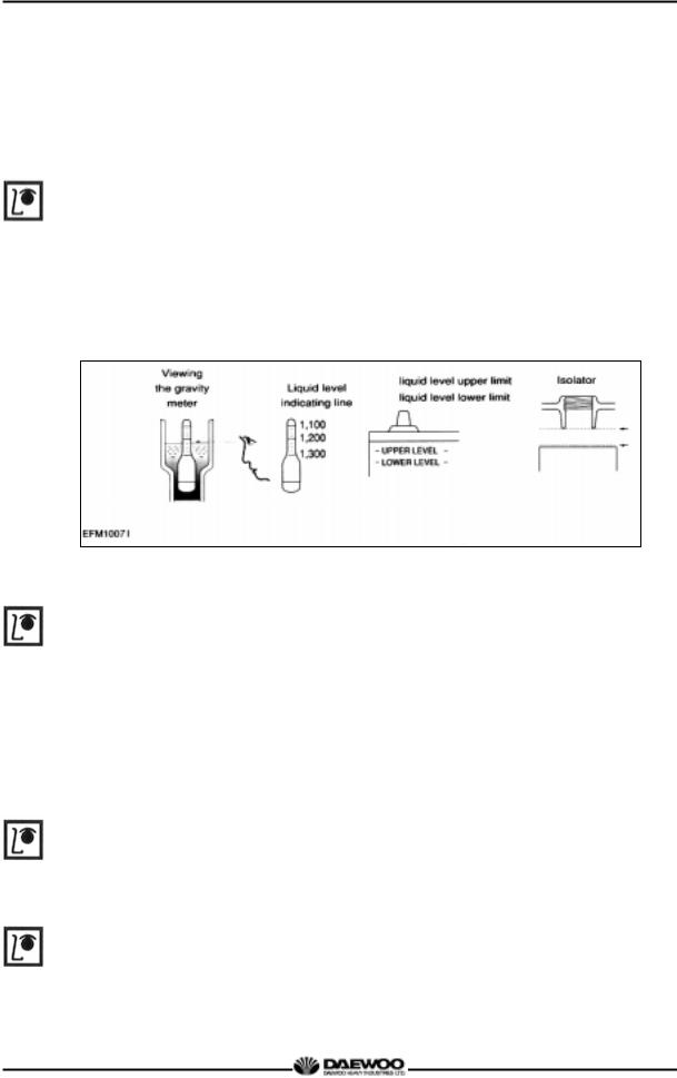
(5)By comparing the hue changed into yellowish green or so with the green color indication of test paper storage bottle, confirm the density. (Then, the density indication must be in the hue range of 33% to 50%).
(6)The brown at the middle of test paper and the lower pink color indication represent the additive state for rust prevention, and the proper range is that the meeting numerical value of brown (vertical) and pink color (horizontal) locates in the range of 0.3 to 0.8 at the color list of label on the test paper storage bottle.
(7)In case of less than 0.3, replenish the additive for rust prevention (DCA4), and in case of more than 0.8, pour out the cooling water about 50% and then readjust the density after refilling with clean fresh water.
zAmount of Anti-freeze in winter
|
Ambient |
Cooling water (%) |
Anti-freeze (%) |
|
|
Temperature (°C) |
|||
|
Over -10 |
85 |
15 |
|
|
-10 |
80 |
20 |
|
|
-15 |
73 |
27 |
|
|
-20 |
67 |
33 |
|
|
-25 |
60 |
40 |
|
|
-30 |
56 |
44 |
|
|
-40 |
50 |
50 |
2.1.2. Fan belt
zUse a fan belt of specified dimensions, and replace if damaged, frayed, or deteriorated.
zCheck the fan belt for belt tension.
If belt tension is lower than the specified limit, adjust the tension by relocating the alternator. (specified deflection: 10 15 mm when pressed down with thumb)
14
Printed in Jan. 2001 PS-MMA0415-E1A
D1146/D1146TI/DE08TIS
MAINTENANCE MANUAL
2.1.3. Engine oil
zCheck oil level with the oil level gauge and replenish if necessary.
z Check the oil level with the engine cooled. If the engine is warm, allow time for 510 minutes for oil drain into the crankcase before checking oil level. The oil level must be between Max and Min. lines on the gauge.
zEngine oil should be changed at the specified intervals. Oil filter cartridge should be changed simultaneously.
— First oil change : 1,000km(50 hr) operating
|
First oil change |
After 1,000km (50hr) |
||
|
operation |
|||
|
Short-distance operation vehicle |
D1146/TI |
every 10,000km |
|
|
(city bus, dump truck) |
DE08TIS |
every 20,000km |
|
|
Long-distance operation vehicles |
D1146/TI |
every 15,000km |
|
|
(express bus, cargo truck) |
DE08TIS |
every 30,000km |
z The following oils are also recommended
|
Engine |
Recommend oil |
Remark |
||
|
model |
SAE No. |
API No. |
||
|
D1146 |
SAE 15W40 |
above CD or CE |
||
|
D1146TI |
||||
|
DE08TIS |
SAE15W40 |
ACEA-E2 or ACEA-E3 |
||
|
SAE10W40 |
(API CH-4) |
|||
*If long oil change intervals are to be used, ACEA-E3 oil must be used.
2.1.4.Oil filter
zCheck for oil pressure and oil leaks, and repair or replace the oil filter if necessary.
zChange the oil filter cartridge simultaneously at every replacement of engine oil.
Oil filter head
Oil filter (Cartridge)
G1081
15
Printed in Jan. 2001 PS-MMA0415-E1A
D1146/D1146TI/DE08TIS
MAINTENANCE MANUAL
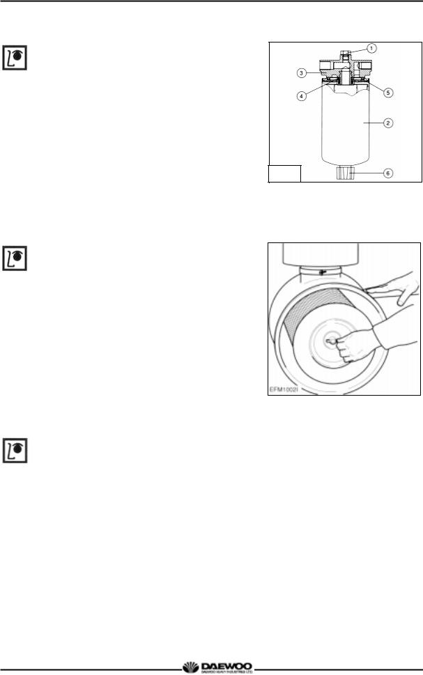
2.1.5. Fuel filter
zDrain water in cartridge with loosening the
cock under filter manually (6) from time to time.
G1019
2.1.6. Air cleaner.
zIn case that elements are deformed, damaged or if the air cleaner has a crack, replace it.
zBy the definite interval, the elements must be cleaned and replaced.
2.1.7. Intercooler
The intercooler is air to air type and has a large
cooling fan capacity. The intercooler life and
performance depends on the intake air condition greatly. Fouled air pollutes and clogs the air fins of intercooler. As a result of this, the engine output is decreased and engine malfunction is occurred. So you always check whether the intake air systems like air filter
element are worn or polluted.
16
Printed in Jan. 2001 PS-MMA0415-E1A
![]()
D1146/D1146TI/DE08TIS
MAINTENANCE MANUAL
Air/air intercooler with radiator (combined radiator)
 Air flow by cooling fan
Hot air by turbo charger compressor
Cooled air to intake manifold (max. 50°C)
2.1.8. Valve clearance adjust procedure
|
zAfter |
letting the #1 cylinder’s piston |
||||
|
come at |
|||||
|
the compression top dead center by turning |
|||||
|
the crankshaft, adjust the valve clearances. |
|||||
|
zLoosen the lock nuts of rocker arm |
|||||
|
adjusting screws and push the feeler gauge |
|||||
|
of specified value between a rocker arm and |
|||||
|
a valve stem and adjust the clearance with |
|||||
|
adjusting screw respectively and then tighten |
|||||
|
with the lock nut. |
|||||
|
z As for the valve clearance, adjust it when in |
|||||
|
cold, as follows. |
|||||
|
Model |
Intake Valve |
Exhaust Valve |
|||
|
D1146 |
|||||
|
D1146TI |
0.3 mm |
0.3 mm |
|||
|
DE08TIS |
|||||
|
1) Rotate the crankshaft to overlap the intake |
|||||
|
and the exhaust valves of #6, then #1 cylinder |
|||||
|
become the compression state of top dead |
|||||
|
center. |
|||||
|
2) Therefore |
adjust the |
valve clearance |
|||
|
corresponding to “ |
” of lower figure. |
At this time there are no force on the push rods of #1 cylinder.
17
Printed in Jan. 2001 PS-MMA0415-E1A

D1146/D1146TI/DE08TIS
MAINTENANCE MANUAL
3)Rotating the crankshaft by one revolution, #6 cylinder become the compression state of top dead center.
4)Thereafter adjust the valve clearances corresponding to “  ” of lower figure.
5)After reinsuring the valve clearances, retighten if necessary.
z No. 1 cylinder is located at the side where flywheel was installed.
|
Flywheel |
Intake Valve |
Exhaust Valve Cylinder No. |
Cooling Fan |
G1048
2.1.9. Cylinder compression pressure
zStop the engine after warming up, and
take out nozzle holder assembly.
G1067
18
Printed in Jan. 2001 PS-MMA0415-E1A
D1146/D1146TI/DE08TIS
MAINTENANCE MANUAL
z Install the special tool (compression gauge adapter) at the nozzle holder hole, and connect the compression pressure gauge there.
|
Standard value |
28kg/cm2 over |
||||
|
Limit value |
24kg/cm2 |
||||
|
Difference |
Within ± 10 % |
||||
|
between each cylinder |
|||||
|
♦ Condition : Water temperature 20°C, |
|||||
|
G1068 |
|||||
|
Engine rotation 200rpm (10 rotations) |
|||||
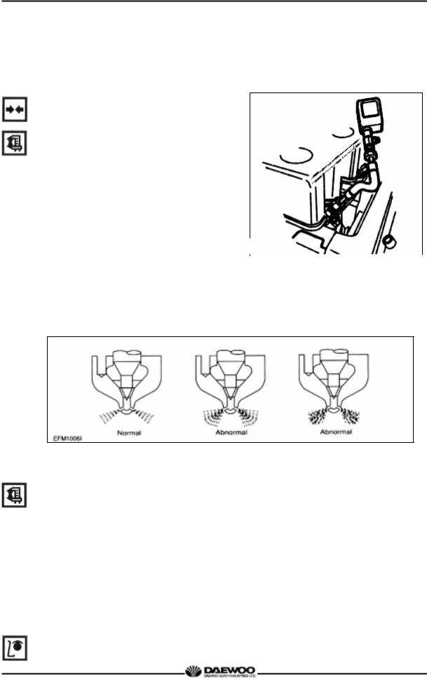
2.1.10. Injection nozzle
z Install a nozzle on the nozzle tester.
zIf the inspected injection pressure is less than the specified value, adjust using the adjusting shims.
|
Engine Model |
D1146 |
D1146TI |
DE08TIS |
||
|
Opening pressure |
210 kg/cm |
2 |
214 kg/cm |
2 |
1st : 160 kg/cm2 |
|
2nd : 220 kg/cm2 |
zCheck the atomizing state and replace it if abnormal.
2.1.11.Fuel injection pump
zCheck the housing crack, damage etc. and replace it if abnormal.
19
Printed in Jan. 2001 PS-MMA0415-E1A
D1146/D1146TI/DE08TIS
MAINTENANCE MANUAL
zCheck if the idle operation and speed regulating lever’s sealing is removed.
z The adjustment and testing of fuel injection pump should necessarily be done at the test bench.
2.1.12. Battery
zInspect for any leakage of electrolytic solution owing to battery crack, and replace
the battery in case of poor condition.
zInspect for amount of electrolytic solution, and replenish if insufficient.
zMeasure the gravity of electrolytic solution, if less than specified value (1.12 1.28), replenish.
2.1.13. Air removal of fuel system
The suction room of fuel injection pump has the function of air removal continuously during the operation through a relief valve.
In case that the suction room lacks fuel at all, for instance, in case of new installation of injection pump, after loosening the air removing screws of cartridge filter respectively, remove the air by operating the manual pump of fuel supply pump until bubble will disappear.
2.1.14. Fuel supply pump
Every time of engine oil replacement, the fuel strainer installed at the fuel supply pump should be removed and cleaned.
2.1.15. Turbocharger
The turbocharger needs not arty special equipment.
Every time of engine replacement, a leakage or clogging of oil pipes should be inspected. Air cleaner should be maintained carefully for nut or foreign material not to get in. Periodic inspection should be applied on the compressed air and exhaust gas
20
Printed in Jan. 2001 PS-MMA0415-E1A

D1146/D1146TI/DE08TIS
MAINTENANCE MANUAL
pipes, For leaking air will bring the overheat engine, an immediate repair must be done.
During the operation that is surrounded by the dust and oil mixed air, frequent cleaning must be done on the impellers. Tear down the impeller casing (attention: be careful not to bend) and must clean with non-acid solvent solution. If necessary, use plastic scraper If impeller is severely polluted, dip the impeller into solution and may be better to clean it with stiff brush.
Then one thing to beware is to dip only impeller part and so do not support by impeller but bearing housing.
2.1.16. Starting motor
In case of engine maintenance, clean pinion and ring gear thoroughly putting in the fuel, and coat them with grease.
Also, In case of washing engine (room) and so forth, inspect the wiring state being careful for water not to get in.
21
Printed in Jan. 2001 PS-MMA0415-E1A
D1146/D1146TI/DE08TIS
MAINTENANCE MANUAL
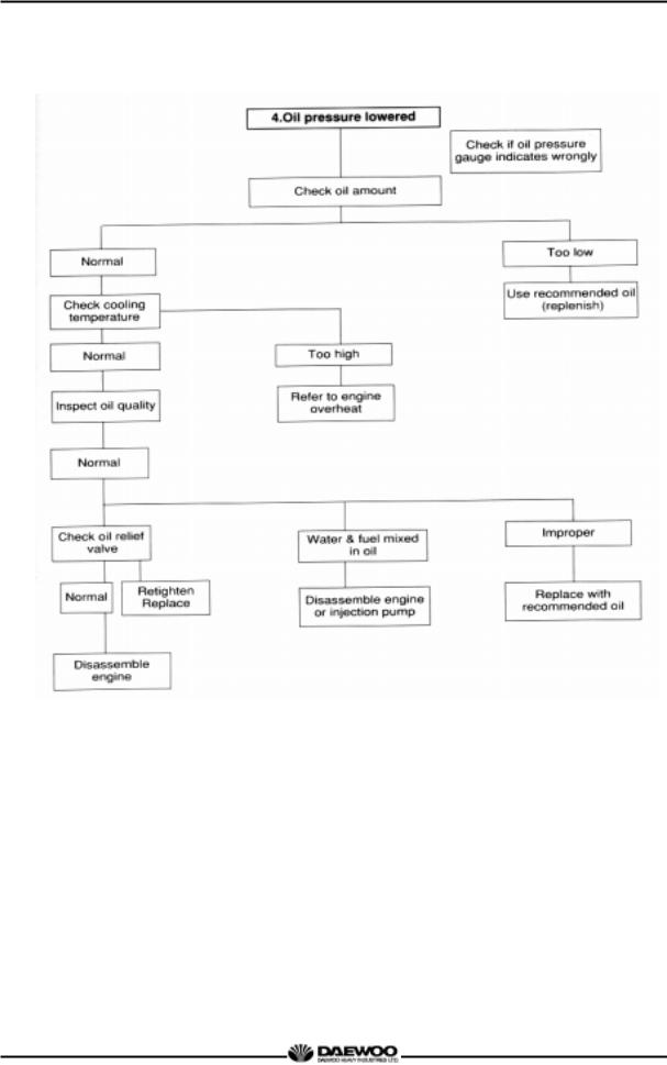
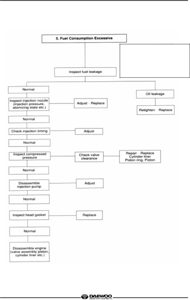
2.2. Diagnosis and Remedy
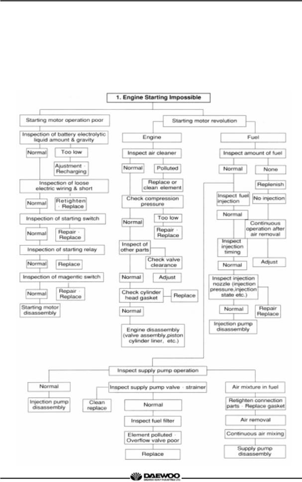
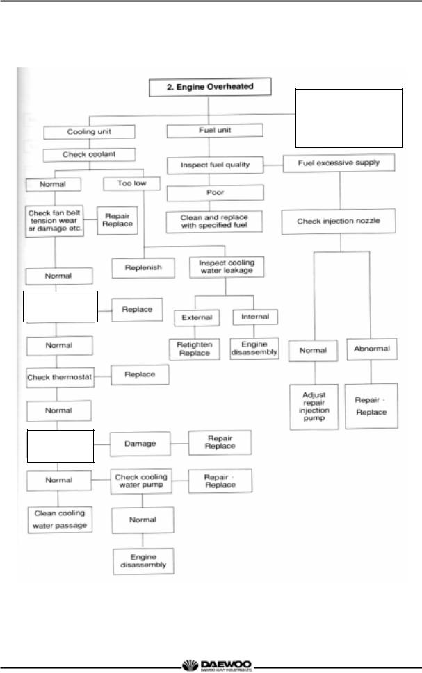
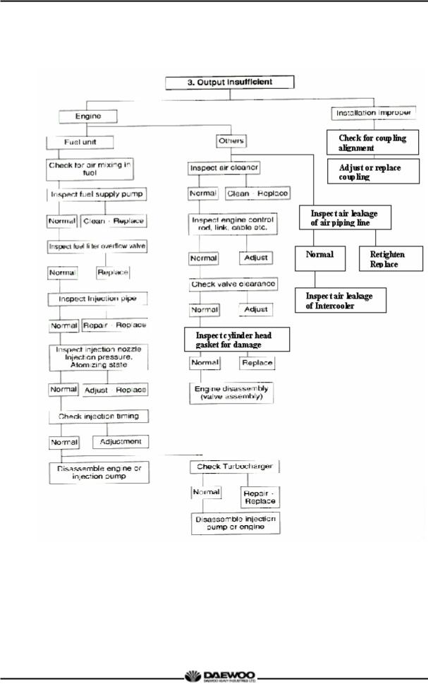
zThe following description summarizes the probable cause of and remedy for generall failure by item.
zImmediate countermeasures should be taken before a failure is inflamed if any symptom is detected.
22
Printed in Jan. 2001 PS-MMA0415-E1A
D1146/D1146TI/DE08TIS MAINTENANCE MANUAL
Check fresh Radiator tank cap
Operating state
1.Overload
2.Radiator core clogged
3.Continuous over-run
Inspect
Radiator
23
Printed in Jan. 2001 PS-MMA0415-E1A
D1146/D1146TI/DE08TIS
MAINTENANCE MANUAL
24
Printed in Jan. 2001 PS-MMA0415-E1A
D1146/D1146TI/DE08TIS
MAINTENANCE MANUAL
25
Printed in Jan. 2001 PS-MMA0415-E1A
D1146/D1146TI/DE08TIS
MAINTENANCE MANUAL
Causes according to operating conditions
1.Overload
2.Freqent use of low geae position at high speed
3.Freqent use of high geae position at low speed
4.Clutch slip
5.Too low tire inflation pressure
26
Printed in Jan. 2001 PS-MMA0415-E1A
![]()
D1146/D1146TI/DE08TIS
MAINTENANCE MANUAL
Cause according to use conditions
1.Excessive oil infusing
2.continuous operation in low speed or extremely cold state
27
Printed in Jan. 2001 PS-MMA0415-E1A

D1146/D1146TI/DE08TIS
MAINTENANCE MANUAL
28
Printed in Jan. 2001 PS-MMA0415-E1A

D1146/D1146TI/DE08TIS
MAINTENANCE MANUAL
|
Condition |
Causes |
Remedies |
|||||||||||
|
1) Starting difficult |
|||||||||||||
|
(1) Compression pressure lack |
z |
Valve’s |
poor |
shut, |
stem |
Repair or replace |
|||||||
|
distortion |
|||||||||||||
|
z |
Valve spring damage |
Replace valve spring |
|||||||||||
|
z Cylinder head gasket’s leak |
Replace gasket |
||||||||||||
|
z Wear |
of |
piston, piston |
ring |
Adjust |
|||||||||
|
or liner |
|||||||||||||
|
2) Idle operation abnormal |
z |
Injection timing incorrect |
Adjust |
||||||||||
|
z Air mixing at injection pump |
Remove air |
||||||||||||
|
3) Engine output insufficient |
|||||||||||||
|
(1) Continuous output |
z |
Valve clearance incorrect |
Adjust |
||||||||||
|
insufficient |
z |
Valve tightness poor |
Repair |
||||||||||
|
z Cylinder head gasket’s leak |
Replace gasket |
||||||||||||
|
z Wear, |
stick, |
damage |
of |
Replace piston ring |
|||||||||
|
piston ring |
|||||||||||||
|
z |
Injection timing incorrect |
Adjust |
|||||||||||
|
z |
Fuel |
injection |
amount |
Adjust injection pump |
|||||||||
|
insufficient |
|||||||||||||
|
z |
Nozzle |
injection |
pressure |
Adjust or replace |
|||||||||
|
improper or stuck |
|||||||||||||
|
z |
Supply |
pump’s |
function |
Repair or replace |
|||||||||
|
lowered |
|||||||||||||
|
z Fuel pipe system clogged |
Repair |
||||||||||||
|
z |
Air |
suction |
amount |
Clean or replace air |
|||||||||
|
insufficient |
cleaner |
||||||||||||
|
(2) Output insufficient |
z |
Turbocharger poor |
Repair or replace |
||||||||||
|
z |
Compression pressure |
Disassemble engine |
|||||||||||
|
when in acceleration |
insufficient |
||||||||||||
|
z |
Injection timing incorrect |
Adjust |
|||||||||||
|
z |
Fuel |
injection |
amount |
Adjust injection pump |
|||||||||
|
insufficient |
|||||||||||||
|
z |
Injection |
pump |
timer’s |
Repair or replace |
|||||||||
|
function insufficient |
|||||||||||||
|
z |
Nozzle |
infection |
pressure, |
Repair, replace |
|||||||||
|
infection angle improper |
|||||||||||||
|
z |
Supply |
pump’s |
function |
Repair or replace |
|||||||||
|
lowered |
|||||||||||||
|
z |
Air intake amount |
Clean or |
|||||||||||
|
insufficient |
replace air cleaner |
||||||||||||
|
4) Overheating |
z |
Engine |
oil insufficient |
or |
Replenish or replace |
||||||||
|
poor |
|||||||||||||
|
z |
Cooling water insufficient |
Replenish or replace |
|||||||||||
|
z |
Fan |
belt |
loosened, |
worn, |
Adjust or replace |
||||||||
|
damaged |
|||||||||||||
|
z |
Cooling |
water |
pump’s |
Repair or replace |
|||||||||
|
function lowered |
|||||||||||||
|
z |
Water |
temp. |
regulator’s |
Replace |
|||||||||
|
operation poor |
|||||||||||||
|
z |
Valve clearance incorrect |
Adjust |
|||||||||||
|
z |
Exhaust system’s resistance |
Clean or replace |
|||||||||||
|
increased |
|||||||||||||
|
29 |
|||||||||||||
|
Printed in Jan. 2001 PS-MMA0415-E1A |

D1146/D1146TI/DE08TIS
MAINTENANCE MANUAL
|
Condition |
Causes |
Remedies |
||||||
|
5) Engine noisy |
For |
noises |
arise |
compositely |
||||
|
such as rotating parts, lapping |
||||||||
|
parts etc., there is necessity to |
||||||||
|
search the cause of noises |
||||||||
|
(1) Crankshaft |
accurately. |
|||||||
|
z |
As the wear of bearing or |
Replace bearing & |
||||||
|
crankshaft |
progress, |
the oil |
grind crankshaft |
|||||
|
clearances increase. |
||||||||
|
z |
Lopsided wear of crankshaft |
Grind or replace |
||||||
|
z |
Oil supply insufficient due to |
Clean oil passage |
||||||
|
oil passage clogging |
||||||||
|
z |
Stuck bearing |
Replace bearing & |
||||||
|
(2) Con.-rod and |
Grind |
|||||||
|
z |
Lopsided wear of con rod |
Replace bearing |
||||||
|
Con.-rod bearing |
bearing |
|||||||
|
z |
Lopsided wear of crank pin |
Grind crankshaft |
||||||
|
z |
Connecting rod distortion |
Repair or replace |
||||||
|
z |
Stuck bearing |
Replace & |
||||||
|
grind crankshaft |
||||||||
|
z |
Oil supply |
insufficiency as |
Clean oil passage |
|||||
|
clogging |
at oil |
passage |
||||||
|
(3) Piston, piston pin & |
progresses |
|||||||
|
z |
Piston |
clearance |
increase |
Replace piston & |
||||
|
Piston ring |
as the wear of piston and |
piston ring |
||||||
|
piston ring progresses |
||||||||
|
z |
Wear of piston or piston pin |
Replace |
||||||
|
z |
Piston stuck |
Replace piston |
||||||
|
z |
Piston insertion poor |
Replace piston |
||||||
|
(4) Others |
z |
Piston ring damaged |
Replace piston |
|||||
|
z |
Wear of crankshaft, |
thrust |
Replace thrust bearing |
|||||
|
bearing |
||||||||
|
z |
Camshaft |
end |
play |
Replace thrust plate |
||||
|
increased |
||||||||
|
z |
Idle gear end play increased |
Replace thrust washer |
||||||
|
z |
Timing |
gear |
backlash |
Repair or replace |
||||
|
excessive |
||||||||
|
z |
Valve clearance excessive |
Adjust valve clearance |
||||||
|
z |
Abnormal |
wear |
of tappet, |
Replace tappet, cam |
||||
|
cam |
||||||||
|
z |
Supercharger |
inner |
part |
Repair or replace |
||||
|
damaged |
||||||||
|
6) Fuel Consumption |
z |
Injection timing incorrect |
Adjust |
|||||
|
Excessive |
z |
Fuel |
injection |
amount |
Adjust injection pump |
|||
|
excessive |
30
Printed in Jan. 2001 PS-MMA0415-E1A

D1146/D1146TI/DE08TIS
MAINTENANCE MANUAL
|
Condition |
Causes |
Remedies |
|||
|
7) Oil Consumption |
|||||
|
Excessive |
|||||
|
(1) Oil level elevated |
z |
Clearance between cylinder |
Replace |
||
|
liner & piston |
|||||
|
z |
Wear of piston ring, ring |
Replace piston, |
|||
|
groove |
piston ring |
||||
|
z |
Piston ring’s damage, stick, |
Replace piston ring |
|||
|
wear |
|||||
|
z |
Piston |
ring |
opening’s |
Correct position |
|
|
disposition improper |
|||||
|
z Piston skirt part damaged or |
Replace piston |
||||
|
abnormal wear |
|||||
|
z |
Oil ring’s oil return hole |
Replace piston ring |
|||
|
clogged |
|||||
|
(2) Oil level lowered |
z Oil ring’s contact poor |
Replace piston ring |
|||
|
z |
Looseness of valve stem & |
Replace in set |
|||
|
guide |
|||||
|
z Wear of valve stem seal |
Replace seal |
||||
|
(3) Oil leak |
z Cylinder head gasket’s leak |
Replace gasket |
|||
|
z |
Looseness of |
connection |
Replace gasket, repair |
||
|
parts |
|||||
|
z Various parts’ packing poor |
Replace packing |
||||
|
z |
Oil seal poor |
Replace oil seal |
31
Printed in Jan. 2001 PS-MMA0415-E1A

D1146/D1146TI/DE08TIS
MAINTENANCE MANUAL
2.3. Engine Inspection
2.3.1. Stopping engine
After checking the engine for any unusual condition at the idling speed, then turn the key switch to stop the engine.
2.3.2. General engine inspection cycle
О : Check & adjust ● : Replace
|
Inspection |
Daily |
Inspection time(km) |
Remark |
|||||
|
1,000 |
10,000 |
15,000 |
20,000 |
40,000 |
||||
|
Check for leakage(hoses, clamp) |
О |
|||||||
|
Cooling |
Check the water level |
О |
||||||
|
System |
Check the V-belt tension |
О |
||||||
|
Change the coolant water |
● |
|||||||
|
Check for leakage |
О |
|||||||
|
Lubrication |
Check the oil level gauge |
О |
||||||
|
Change the lubricating oil |
● |
(О) |
||||||
|
System |
1st |
|||||||
|
Replace the oil filter cartridge |
● |
(О) |
||||||
|
1st |
||||||||
|
Intake & |
Check the leakage for intercooler |
О |
||||||
|
(hoses, clamp) |
||||||||
|
Exhaust |
||||||||
|
Clean and change |
О |
|||||||
|
System |
the air cleaner element |
|||||||
|
Drain the water in separator |
О |
|||||||
|
Clean the fuel strainer |
О |
|||||||
|
of fuel feed pump |
||||||||
|
Fuel |
Check the fuel line leakage |
О |
||||||
|
Check fuel Injection timing |
When |
|||||||
|
System |
necessary |
|||||||
|
Replace the fuel filter cartridge |
● |
|||||||
|
Check the injection nozzles |
When |
|||||||
|
necessary |
||||||||
|
Check the exhaust gas state |
О |
|||||||
|
Engine |
Check the battery charging |
О |
||||||
|
Check the compression pressure |
When |
|||||||
|
Adjust |
О |
|||||||
|
necessary |
||||||||
|
Adjust Intake/Exhaust |
When |
|||||||
|
valve clearance |
necessary |
*(О) The engine oil change interval is determine by engine use and oil grade.
2.3.3.Use of original parts for repair and replacement
For engine is being mechanically harmonized with many parts, only when the original parts that the manufacture recommends to use is used, the engine trouble would be preventively maintained and capable to keep up the maximum performances.
For the analogous parts not the original parts are poor in qualities and gives illl performances, it may rather bring early engine failure.
32
Printed in Jan. 2001 PS-MMA0415-E1A

D1146/D1146TI/DE08TIS
MAINTENANCE MANUAL
3. MAINTENANCE
3.1. Engine Disassembly
3.1.1. Heed at disassembly
zBefore disassembly, the part shelf should be prepared for various tools and repair parts.
zWhen assembling, clean empty hand should be used and clean environment maintained.
zIn case of storing the disassembled parts, each part should not touch each other.
zIn case of disassembly, the parts should be laid in order.
3.1.2.Oil level gauge
zPull out the oil level gauge.
3.1.3.Cooling water
zRemove the radiator cap. Open the drain
valve at the radiator lower part to drain the
coolant as the right figure.
CAUTION:
When removing radiator filler cap while
the engine is still hot, cover the cap with a rag,
then turn it slowly to release the internal Drain valve
P1024a
steam pressure. This will prevent a person from scalding with hot steam spouted out from the filler port.
z Remove the drain plug from the cylinder block and drain out the cooling water into a container.
Drain plug
33
Printed in Jan. 2001 PS-MMA0415-E1A

D1146/D1146TI/DE08TIS
MAINTENANCE MANUAL
3.1.4. Engine oil
zRemove the oil drain plug of oil pan and pour the engine oil into the prepared vessel.
3.1.5. Cooling fan
zRemove the flange fixing bolts, then take off the flange and cooling fan.
3.1.6. Belt
zLoosen the tension adjusting bolts of the alternator and the idle pulley, and take off the belts.
3.1.7. Thermostat
zLoosen the rubber hose connected to the cooling water pipe and remove the thermostat.
zRemove the rubber hose of the by-pass line.
34
Printed in Jan. 2001 PS-MMA0415-E1A

D1146/D1146TI/DE08TIS
MAINTENANCE MANUAL
3.1.8. Starter
zUnscrew the starter fixing nuts and remove the starter being careful not to damage its gears.
3.1.9.Fuel filter
zRemove the hollow screws of filter and tear down fuel supply and discharge rubber hose.
zRemove fuel filter fixing bolts and disassemble the fuel filter.
(If the fuel filter is of cartridge type, disassemble the cartridge element only.)
3.1.10. Breather
zLoosen the clamp screw to remove the rubber hose.
3.1.11.Intercooler (D1146TI, DE08TIS)
zTear down the various hoses and air pipes from the inter cooler.
zRemove the intercooler fixing bolts and tear it down.
P068
35
Printed in Jan. 2001 PS-MMA0415-E1A

D1146/D1146TI/DE08TIS
MAINTENANCE MANUAL
3.1.12. Alternator
zRemove the alternator fixing bolts and take off the alternator.
3.1.13. Oil cooler
zLoosen the cooling water pump and the rubber hose clamps of connected pipes, and disassemble it.
zRemove the oil cooler fixing bolts and take off the oil cooler.
3.1.14.Oil filter
zRemove the oil filter fixing bolts and take off the oil filter.
3.1.15. Power steering pump
zRemove the oil hose between power steering oil pump and control unit of the vehicle.
zUnscrew the power steering oil pump fixing bolts and remove the power steering pump.
36
Printed in Jan. 2001 PS-MMA0415-E1A
![]()
D1146/D1146TI/DE08TIS
MAINTENANCE MANUAL
3.1.16. Air compressor
zRemove the oil pipe between cylinder block and air compressor.
zUnscrew the air compressor fixing bolts and take off the air compressor.
3.1.17.Idle pulley
zUnscrew the idle pulley fixing bolts and take off the idle pulley
3.1.18. Water pump
zUnclamp the rubber hose connected to the oil cooler.
zUnscrew the water pump fixing bolts from the cylinder block and take off the water pump.
3.1.19.Cylinder head cover
zRemove the head cover fixing bolts and lift the cylinder head cover.
37
Printed in Jan. 2001 PS-MMA0415-E1A

D1146/D1146TI/DE08TIS
MAINTENANCE MANUAL
3.1.20. Fuel injection nozzle
zUnscrew the fuel injection pipe between the injection pump and nozzle and take off the pipe.
zInstall a special jig on the nozzle holder, and then pull out the nozzle as striking the hammer of the jig backwardly.
Take care not to damage the nozzle at disassembly.
zTake out the seal ring from the nozzle hole of the cylinder head and discard it.
3.1.21.Turbo charger (D1146TI, DE08TIS)
zRemove the oil supply pipe and oil return pipe between the turbo charger and the cylinder block.
zUnclamp the rubber hose connected the intercooler and air cleaner.
zUnscrew the turbo charger fixing nuts and take off the turbo charger from the exahust manifold.
3.1.22.Exhaust manifold
zUnscrew the exhaust manifold fixing nuts and remove the heat shield from the exhaust manifold.
zThen disassemble the exhaust manifold and gasket.
zScrap the used gasket.
38
Printed in Jan. 2001 PS-MMA0415-E1A

|
D1146/D1146TI/DE08TIS |
||||||||||||
|
MAINTENANCE MANUAL |
||||||||||||
|
3.1.23. Intake manifold |
||||||||||||
|
z |
Unscrew the intake manifold fixing bolts |
|||||||||||
|
and remove the intake manfold from the |
Air heater |
Intake manifold |
||||||||||
|
cylinder head. |
||||||||||||
|
z |
Disassemble the intake manifold gasket |
|||||||||||
|
and discard it. |
||||||||||||
|
3.1.24. Cooling water pipe |
||||||||||||
|
z |
Unscrew the cooling water pipe fixing |
|||||||||||
|
bolts and remove the cooling water pipe |
||||||||||||
|
from the cylinder head. |
||||||||||||
|
z |
Remove the cooling water pipe gasket |
|||||||||||
|
and finish the surface with a scraper. |
||||||||||||
|
CAUTION : |
||||||||||||
|
Be sure that piece of the gasket do |
||||||||||||
|
not come into the cooling water |
||||||||||||
|
passage. |
||||||||||||
|
3.1.25. Rocker arm |
||||||||||||
|
z |
Remove the rocker arm bracket fixing |
|||||||||||
|
bolts in reverse order (zigzag method) of |
||||||||||||
|
assembling and disassemble the rocker |
||||||||||||
|
arm. |
||||||||||||
|
z Take out the push rod upwards. |
||||||||||||
|
z Disassembly of rocker arm assembly |
G1088 |
|||||||||||
|
— Remove the snap ring fron the both |
||||||||||||
|
ends of rocker arm shaft by means of a |
||||||||||||
|
plier. |
||||||||||||
|
— Remove the washer, rocker arm, |
||||||||||||
|
bracket and spring from the rocker arm |
||||||||||||
|
shaf in sequence. |
||||||||||||
|
— Press out the rocker arm bush. |
||||||||||||
|
G1056 |
||||||||||||
|
39 |
||||||||||||
Printed in Jan. 2001 PS-MMA0415-E1A

D1146/D1146TI/DE08TIS
MAINTENANCE MANUAL
CAUTION :
When reassembling the bush, cool the bush in dry ice and press the bush while aligning the bush with the oil hole of the rocker arm.
3.1.26. Cylinder head
zRemove the cylinder head bolts in the reverse order of tightening but remove it
step by step.
First step : Loosen 1 2 threads
Second step : Remove by loosening fully.
However, remove the total bolts G1089 simultaneously by the step of 1 and 2.
zLay the removed bolts orderly not to damage the threads at all and store.
CAUTION :
Prevent a collision between the bolt thread each other.
zTake out the cylinder head gasket and scrap it.
zRemove the foreign residues from the cylinder head surface and block surface.
CAUTION :
Try not to make any damage on the contact surfaces.
zDisassembly of cylinder head
—Place the cylinder head on a individual shelf.
—As pressing the valve spring with a special tool, remove the cotter pin, valve spring.
—Take out the intake and exhaust valves.
40
G1102
Compress the spring
Printed in Jan. 2001 PS-MMA0415-E1A

D1146/D1146TI/DE08TIS
MAINTENANCE MANUAL
—For removal of the valve seat, apply arc welding work to two points of valve seat insert, and pull out the valve seat insert with inner extractor.
M1072
3.1.27. Oil pan
zUnscrew the oil pan fixing bolts and remove the oil pan.
zRemove the oil pan gasket and discard it.
3.1.28.Vibration damper
zUnscrew the vibration damper fixing bolts in reverse sequence of installing sequence and remove the vibration damper assembly.
G1090
3.1.29. Timing gear case cover
z Disassemble the oil seal using an oil seal removing jig.
zRemove the cover fixing bolts and disassemble the cover from the timing gear case.
41
Printed in Jan. 2001 PS-MMA0415-E1A
- Manuals
- Brands
- Doosan Manuals
- Engine
- DE08TIS Series
- Operation & maintenance manual
Diesel industrial engine
Hide thumbs
1
2
3
4
5
6
7
8
9
10
11
12
13
14
15
16
17
18
19
20
21
22
23
24
25
26
27
28
29
30
31
32
33
34
35
36
37
38
39
40
41
42
43
44
45
46
47
48
49
50
51
52
53
54
55
56
57
58
59
60
61
62
63
64
65
66
67
68
69
70
71
72
73
74
75
76
77
78
79
80
81
82
83
84
85
86
87
88
89
90
91
92
93
94
95
96
97
98
99
100
101
102
103
104
105
106
107
108
109
110
111
112
113
114
115
116
117
118
119
120
121
122
123
124
125
126
127
128
129
130
131
132
133
134
135
136
137
138
139
140
141
142
143
Table Of Contents
144
-
page
of
144/
144 -
Contents
-
Table of Contents
-
Troubleshooting
-
Bookmarks
Advertisement
Table of Contents
1. GENERAL INFORMATION
1.3.2 Engine power
Engine Model
Product
Model
Code
DE08-PBL00
DE08TIS
MBE00
Performance
Power
Torque
(kgf•m/RPM)
(PS/RPM)
217.6/2,000
92/1,300
212/1,800
85/1,400
4
Production tolerance : ±5%
Low Idle
High Idle
(RPM)
(RPM)
850
2,200
1,000
2,000
Remark
Table of Contents
Previous Page
Next Page
- 1
- …
- 7
- 8
- 9
- 10
- 11
- 12
- 13
- 14
Show Quick Links
- Quick Links:
-
Engine Reassembly
Hide quick links:
Advertisement
Table of Contents
Related Manuals for Doosan DE08TIS Series
-

Engine Doosan DE12T Operation & Maintenance Manual
(176 pages)
-
Engine Doosan DE08TS Disassembly/Assembly
(78 pages)
-
Engine Doosan DE08TS Manual
For d100, d120, d150, d110s-5, d130s-5, d160s-5 (108 pages)
-
Engine Doosan DE12 Series Operation & Maintenance Manual
Diesel vehicle engine (158 pages)
-
Engine Doosan DV11 Operation And Maintenance Manual
(220 pages)
-
Engine Doosan DV11 Operation And Maintenance Manual
(221 pages)
-
Engine Doosan DB33A Service Manual
Diesel engine 3.3 liter (79 pages)
-
Engine Doosan D35S-5 Service Manual
(152 pages)


-
Engine Doosan D35S-5 Service Manual
(366 pages)
-
Engine Doosan DP158LCF Operation & Maintenance Manual
Generator diesel engine (160 pages)
-
Engine Doosan DL06 Operation Manual
Interim tier iv (211 pages)
-
Engine Doosan DL06 Manual
(207 pages)
-
Engine Doosan DP158L Series Operation & Maintenance Manual
Diesel generator engine (262 pages)
-
Engine Doosan D1146 Installation Operation & Maintenance
(179 pages)
-
Engine Doosan DX22 Operation & Maintenance Manual
Generator engine (208 pages)
-
Engine Doosan MD Series Installation Instructions Manual
Md, l, v series marine diesel engine (91 pages)


Related Content for Doosan DE08TIS Series
-
GL08K Engine Power
Doosan GL08K
-
DL06 Engine Power
Doosan DL06
-
DL06 Engine Power
Doosan DL06
-
DV11 Engine Power
Doosan DV11
-
G420F Engine Power And Torque
Doosan G420F
-
G424FE G424F/G424Fe Engine Power And Torque
Doosan G424FE
-
DV11 Engine Power
Doosan DV11
-
D1146 Regulations Designed To Prevent Damage To Engine And Premature Wear
Doosan D1146

-
DE12 Series Engine Characteristics
Doosan DE12 Series
-
GV158TIC Safety Regulations & Engine Specifications
Doosan GV158TIC
-
G643E Engine Model And Engine Serial Number
Doosan G643E
-
DE08TS Engine Specific Character
Doosan DE08TS
-
V158TI Engine Specification
Doosan V158TI
-
DP158L Series Precautions In Starting The Engine
Doosan DP158L Series
-
DE08TS Engine And Transmission
Doosan DE08TS
-
PU158TI Engine Power For Generator
Doosan PU158TI


This manual is also suitable for:
De08tis pbl00De08tis mbe00
- Home
- Brands
- Doosan
- Engine
- DE08TIS Series
- Operation & Maintenance Manual
Manual for Doosan DE08TIS Series Engine (143 pages)
Specifications:
|
Doosan DE08TIS Series: Read PDF Manual Online
Accompanying Data:
Doosan DE08TIS Series Engine PDF Operation & Maintenance Manual (Updated: Saturday 14th of January 2023 05:45:09 AM)
Rating: 4.3 (rated by 96 users)
Compatible devices: D110S-5, G424FE, G643E, PU158TI, A2300, DV11, G430 LP, D40S-5.
Recommended Documentation:
Doosan DE08TIS Series: Text of Operation & Maintenance Manual
(Ocr-Read Version Summary of Contents, UPD: 14 January 2023)
-
77, 3. MAINTENANCE 71 ·With the oil port on the idle gear pin facing the cylinder block, install the idle gear pin. · Idler gear pin with oil hole is assembled toward cylinder block. ·Install the idle gear by coinciding the marks impressed on the crank gear, cam gear, fuel injection pump drive gear, and idle gear. ·Install a…
-
96, 4. MAINTENANCE OF MAJOR COMPONENTS 90 ·Replacing thermostat and precautions for handling (1) Precautions for handling The wax pallet type thermostat does not react as quickly as bellows type one to a variation of temperature of coolant. Such relatively slow reaction is mainly due to the large heat capacity of the wax pellet type thermo…
-
14, 1. GENERAL INFORMATION 8 1.4.2 Engine sectional view (cross) 9. Turbo charger 1. Fuel injection pipe 2. Fuel filter 10. Fuel injection pump 3. Fuel injection nozzle 4. Intake manifold 11. Timing gear case 12. Oil filler cap 5. Air heater 6. Rocker…
-
65, 3. MAINTENANCE 59 4) Piston pin inspection (1) Wear Measure the amount of wear on the piston pin at the points as shown. The measured values are beyond the limit (0.08 mm or greater), replace the pin. (2) Clearance Measure the clearance between the piston pin and connecting rod bushing, and replace either of them, whichever…
-
38, 3. MAINTENANCE 32 3.1.16 Air compressor ·Remove the oil pipe between cylinder block and air compressor. ·Unscrew the air compressor fixing bolts and take off the air compressor. 3.1.17 Idle pulley ·Unscrew the idle pulley fixing bolts and take off the idle pulley. 3.1.18 Water pump ·Unclamp the rubb…
-
72, 3. MAINTENANCE 66 ·Install a guide bar into a bolt hole on the crank shaft, and lift the flywheel to align the dowel pin with the pin hole on the flywheel for temporary assembly operation. ·Coat the adhesive (#271 Loctite) over the assembling bolts and install bolts in the remaining holes. After that take out the guide bar, then install a b…
-
140, — 7 — 43 Valve Stem Seal Jig 86 0104-03878 ● 44 Compression Adapter 86 0104-03888 ● 45 INJ Pump Fix Jig 86 0104-00261 ● 46 Camshaft Ass embly Guide 860104-03893 ● 47 Wearing Insert 86 0104-03873 ● 48 Flywheel O-ring Assembly Jig 860104-03628 ● 49 FR Oil Seal Assembly Jig 860104-00932 ● No. Figure Part Number Part Name Engine Model DB58 DE08 DL01 DL02 DL03…
-
76, 3. MAINTENANCE 70 · When the connecting rod bearing cap bolts are tightened, check the connecting rod end play to the right and left with hand. If no end play is found, remove and reinstall or replace the connecting rod bearing cap. 3.3.13 Timing gear case ·Mount a new gasket using dowel pin on the …
-
67, 3. MAINTENANCE 61 3.3 Engine Reassembly 3.3.1 General precautions ·Clean all the disassembled parts, particularly oil and water ports, using compressed air, then check that they are free from restrictions. ·Arrange the general and special tools in order for engine assembly operation. ·To wet each sliding part, prepare the clean engine o…
-
93, 3. MAINTENANCE 87 c) Watch the engine water temperature gauge and be sure there is proper water circulation. The water temperature gauge needle will fluctuate if water level in expansion tank is too low. At the end of the break-in period, remove break-in oil and replace the oil filter. Fill oil pan with recommended engine oil. Refer to fol…
-
89, 3. MAINTENANCE 83 3.3.36 Fuel filter ·Assemble the fuel filter with the intake manifold. ·Assemble the fuel feed hose according to the direction of an arrow impressed on the fuel filter head so that fuel can be fed in the sequence of FUEL FEED PUMP FUEL FILTER FUEL INJECTION PUMP. 3.3.37 Injection nozzle ·Install a…
DOC-f52844a7:
Doosan DE08TIS Series: Recommended Instructions
Commercial 1750, PT813, ECLIPSE MATRIX, XC2100 Series


-
Robert Bosch GmbHBosch eBike Systems72703 ReutlingenGERMANYwww.bosch-ebike.com0 275 U07 XSC (2016.04) T / 28 Active Line/Performance Line Active Line/Performance LineAge: 16+This manual contains important safety, performance and service information. Read and understand it along with the information provided to you by your bicycle manufacturer before using the p …
Active Line 28
-
–190-10199Z10135 150 175 OptimaxF PEGB2000 90-10199Z10 400 � …
Optimax 135 85
-
Operator’s ManualBRIGGSandSTRATTON.comECopyright Briggs & Stratton CorporationMilwaukee, Wisconsin 53201 U.S.A.Form No. 276344-9/06Printed in U.S.A.Models Covered in ThisManual Include Gasoline,Natural Gas and LiquidPropane Gas EnginesModel 210000Power BuiltIntekI/CModel 280000IntekI/CExtended Life SeriesModel 310000IntekI/CExtended Life Series …
210000 20
-
CREATING POWER SOLUTIONS.OPERATOR’S MANUALDiesel engineHatz Diesel1B30Vwww.HATZ-DIESEL.comINCLUDES SUPPLEMENTAL INFORMATION TO THE OWNER’S MANUAL FOR MODEL YEAR 2018 EPA CERTIFIED NONROAD COMPRESSION-IG-NITION ENGINES.INCLUDES SUPPLEMENTAL INFORMATION FOR THE USE OF EPA CERTIFIED ENGINES WITHIN CALIFORNIA. …
1B30V 100
-
24 590 44 Rev. AKohlerEngines.comENOwner’s ManualIMPORTANT: Read all safety precautions and instructions carefully before operating equipment. Refer to operating instruction of equipment that this engine powers. Ensure engine is stopped and level before performing any maintenance or service. Warranty coverage as outlined in the warranty card and on Kohle …
Command PRO Series 52
-
[email protected] OPERATOR’S MANUAL INCLUDING: OPERATION, INSTALLATION & MAINTENANCE Form 49999-055 50 SERIES POWER UNIT Model 8133 3200 R.P.M. Edition 3 April 2000 10589471 WARNING READ THIS MANUAL CAREFULLY BEFORE INSTALLING, OPERATING OR SERVICING THIS EQUIPMENT. FAILURE TO OBSERVE THE FOLLOWING WARNINGS COULD RESULT IN INJURY. Pneumatic too …
50 SERIES 8
-
Introduction of engine OM 471 andexhaust aftertreatmentIntroduction into Service ManualDaimler AG, GSP/OI, HPC R 822, D-70546 StuttgartBestell-Nr. 6517 1260 02 — HLI 000 000 02 82 – Printed in Germany – 09/11Introduction of engine OM 471 and exhaust aftertreatment– This printout will not be recorded by the update service. Status: 09 / 2011 – …
OM 471 225
-
CH18-CH25, CH620-CH730, CH740, CH750Service Manual2 Safety3 Maintenance5 Specications15 Tools and Aids18 Troubleshooting22 Air Cleaner/Intake23 Fuel System29 Governor System31 Lubrication System33 Electrical System49 Starter System58 Clutch60 Disassembly/Inspection and Service75 ReassemblyIMPORTANT: Read all safety precautions and instructions carefully befor …
Command PRO CH18 92
-
BDA SEL-Plus-R 06/2008 1Ergänzungsanleitung SEL Plus-R Wichtige Hinweise für die Erstinbetriebnahme der Funkantriebe SEL Plus-R Funktion: Der SEL Plus-R Antrieb fährt gegen den oberen Anschlag der Anlage, deshalb muss eine Endschiene verbaut sein. Unten muss eine Begrenzung montiert sein (Fensterbank), auf die der Rollladen „aufläuft“. Der SEL Plus-R Antrieb sucht im Automati …
SEL Plus-R 4
-
Robert Bosch GmbH72757 ReutlingenGermanywww.bosch-ebike.com0 275 007 3D1 (2021.06) T / 51 WEUde Originalbetriebsanleitungen Original operating instructionsfr Notice d’utilisation d’originees Instrucciones de servicio originalespt Manual de instruções originalit Istruzioni d’uso originalinl Oorspronkelijke gebruiksaanwijzingda Original brugsanvisningsv Originalbruksanvisningno …
Performance Line CX 51
Additional Information:
Popular Right Now:
Operating Impressions, Questions and Answers:
Только оригинальные руководства
Доступно сразу после оплаты
Полное соответствие бумажным изданиям
100% защита ваших оплат
Издательство: © «Motorist»
ISBN: 978-039-000-329-4
Количество страниц: 146
Формат: файл PDF
О руководстве
Тип двигателя: Daewoo D1146 / D1146TI / DE08TIS
В руководстве вы найдете
- Пошаговое руководство по ремонту различных узлов и агрегатов
- Инструкцию по самостоятельному уходу и обслуживанию
- Сведения о конструкции двигателя и о том как предупредить неисправность
- Информацию для поездки на СТО, если самостоятельный ремонт невозможен
Содержание
Общая информация
- Общие инструкции по ремонту
- Специфика двигателя
- Технические характеристики двигателя
- Сборка двигателя
Капитальный ремонт двигателя
- Профилактика
- Диагностика и устранение неисправностей
- Осмотр двигателя
Техническое обслуживание
- Разборка двигателя
- Осмотр основных деталей
- Повторная сборка
- Обкатка
Обслуживание основных компонентов
- Система охлаждения
- Система смазки
- Топливный насос высокого давления
- Турбокомпрессор
Список специальных инструментов
Приложение
Написать отзыв
Ваше Имя:
Ваш отзыв:
Оценка:
Отзывы покупателей
Thanks for the book I have been looking for this information for a long time