- Manuals
- Brands
- Delem Manuals
- Controller
- DA-52
- Reference manual
-
Contents
-
Table of Contents
-
Bookmarks
Quick Links
DA-52
Reference Manual
Operation of Version 1
English
Manual version V0608
Related Manuals for Delem DA-52
Summary of Contents for Delem DA-52
-
Page 1
DA-52 Reference Manual Operation of Version 1 English Manual version V0608… -
Page 2
Preface This manual describes the operation of the Delem controller type DA-52 and is meant for operators who are instructed for operation of the total machine. Delem Limited warranty • This manual does not entitle you to any rights. Delem reserves the right to change this manual without prior warning. -
Page 3: Table Of Contents
Table of contents 1. Operation overview and general introduction ….1.1 1.1. The control unit ……….. . 1.1 1.2.
-
Page 4
V0208, 2… -
Page 5: Operation Overview And General Introduction
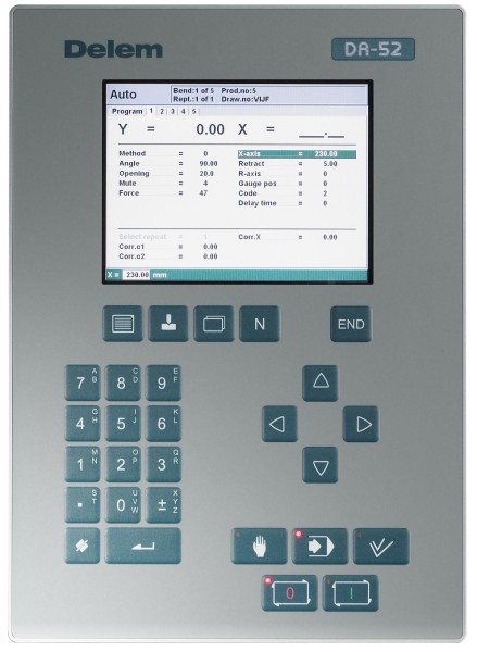
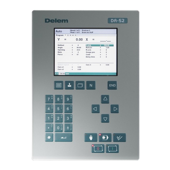
Operation overview and general introduction 1.1. The control unit The control looks as follows: screen function keys arrow keys mode keys numeric keys start/stop The precise outfit of your control may vary. Operation of the control is done with the various keys on the front panel. A description of all keys and their functions is given in the next section.
-
Page 6: Operation Modes
1.2. Operation modes The control has the 3 following modes: Manual mode In this mode it is possible to program all parameters of just one bending. This mode is useful for testing and for calibration. Programming In this mode bend programs can be mode programmed and executed.
-
Page 7: Programming Modes
1.3. Programming modes The control has the following programming functions: Program In this mode you program the general constants parameters for bend programming. Tools In this mode you program and edit the tools. There are 30 different punches and 30 different dies to program in the program memory.
-
Page 8: Other Frontpanel Keys
1.4. Other frontpanel keys The frontpanel consists of the following items: Keyboard: 10 numerical keys (0- 9) incl. alphanumeric input decimal point plus/minus toggle clear key: Clearance of the input data field enter key, to confirm a in the bottom left programmed value corner on the monitor screen…
-
Page 9: Software Versions
Return to previous function or abort parameter edit. Keyswitch The control has a keyswitch to prevent uncontrolled programming. With the keyswitch in the off position only a selected program can be executed. The parameters cannot be changed to wrong, unwanted values. 1.5.
-
Page 10
V0608, 1.6… -
Page 11: Product Programming
Product programming 2.1. Program selection To edit or create a program, proceed as follows: Press this key to activate the automatic mode. Press this key to open the program library. The program library screen appears. Use the arrow keys to move to the desired program in the list. Use the ‘enter’…
-
Page 12: Program Edit
A program can also be selected by entering its number directly. To create a new program, type a number that does not exist yet. When entered, the control asks whether or not to create a new program. Use the ‘clear’ key to delete a program. Confirm this by pressing ENTER.
-
Page 13: Parameters Explanation
Use the arrow keys left/right to browse between the various pages of the bend program. After pressing the enter key the programmed value will be placed at the corresponding parameter. 2.2.2. Parameters explanation Drawing number ……….DN A name or description of the program.
-
Page 14
Die ……….. . .UN Number of die in library. -
Page 15: Bend Programming
2.3. Bend programming 2.3.1. Introduction The parameters of one bend are divided over 2 screen pages. The bend number, product number and drawing number are displayed in the top row on the screen. Use the key ‘change view’ to switch to another page with bend parameters.
-
Page 16
air bend The sheet is bent to the programmed angle by bringing the punch to the required depth. The control calculates the required Y-axis position to obtain the programmed angle. bottoming The sheet is bent by squeezing the sheet between the punch and the die. The control assumes the bottom of the die as required Y- axis position. -
Page 17: Bend Parameters — Second Page
parameters of these axes appear here. 2.3.3. Bend parameters — second page This page contains the additional parameters of a bend. Force…………P The required force during pressing (auto computed).
-
Page 18
parameters active). 1 = Step change at muting position when the beam moves in opening direction. 2 = Step change at upper dead point. 3 = Step change at upper dead point without movement of any axis and the control goes to «stop». -
Page 19
V0608, 2.9… -
Page 20
V0608, 2.10… -
Page 21: Programming Of Tools
Programming of tools 3.1. Introduction This chapter describes the programming of the tools. Press this key for tool programming. The first time this key is pressed, the screen for punch programming appears. To switch to programming of bottom dies, press this key again.
-
Page 22: Punch Parameters
3.2.2. Punch parameters Height………..H The height of the tool.
-
Page 23: Die Parameters
3.3.2. Die parameters Height ………..H The height of the tool.
-
Page 24
computed automatically from the die dimensions as follows: X-SAFE = FS + ½ V in which: FS = flat section on the back side of the V-grove V = opening value In this formula also a small additional safety value (0.5 mm) has been added. Resistance . -
Page 25: Program Constants
Program Constants 4.1. Introduction Press this key to enter the program constants. The program constants are divided across several pages. They are discussed in the following sections. 4.2. General Use the arrow keys left/right to browse through the various pages with parameters. Use the arrow keys up/ down to select individual parameters.
-
Page 26
Ton/kN select……….TS 1 = Ton 0 = kN It is possible to select the units for all Force data to be expressed in Tons or kN. -
Page 27: Materials
4.3. Materials In this window, material properties can be programmed. You can edit existing materials, program new materials or delete existing materials. A maximum of 6 materials can be programmed on the control. For each material, three properties are present and can be viewed and edited. Material name.
-
Page 28: Program Settings
4.4. Program settings Machine number ……… .MN When there are several bending machines in a factory, it can be useful to give the control on each machine a unique machine number.
-
Page 29
properties as the active bend. The following properties of a bend are compared: — Material properties — Thickness — Die opening — Die radius — Punch radius — Angle The first five properties of a bend must be exactly the same as the active bend to start a comparison. -
Page 30: Computation Settings
4.5. Computation settings Data preparation bend allowance ……BA 0 = correction off / 1 = correction on With this parameter you can choose whether or not you wish to have programmed values corrected for bend-allowance.
-
Page 31: Production Settings
4.6. Production settings Stock count mode ………SC Setting for the stock counter in production mode, to have the stock counter (product counter) count up or down.
-
Page 32
axis. The value 0 disables this functionality. When programmed not equal to zero this position will be active when the X-axis has to move inside the safety zone of the die. V0608, 4.8… -
Page 33: Backgauge Dimensions
4.7. Backgauge dimensions With these finger dimensions the R-axis movement and workpiece/backgauge collision can be computed. Gauge R offset ……….RO = An offset value for the R-axis can be set if the backgauge is positioned against the sheet edge and the X-axis position is outside the die safety zone.
-
Page 34: Maintenance
4.8. Maintenance Hours ……….. The number of hours the machine is running.
-
Page 35: Data Transfer
4.9. Data transfer From this menu, all program data on the control can be stored on an external USB device or restored from such a device. Backup products Copy all products from the control to the USB disk. Existing products on the USB disk with the same name are replaced.
-
Page 36
V0608, 4.12… -
Page 37: Manual Mode
Manual mode 5.1. Introduction Manual mode By pushing this key the CNC is in manual mode. In manual mode you program the parameters for one bending. After pushing the ‘Start’ button all parameters are active and the backgauge will go into position.
-
Page 38
Material ……….MA Selection of one of the programmed materials, which are used to calculate the bending depths. -
Page 39
Decompression ……… ..BP Decompression stroke after the bending to release the working pressure. -
Page 40: Zoomed Values
Parallelism ……….Y2 Difference of left- and right hand side cylinder (Y1 and Y2).
-
Page 41: Manual Operation Of The Axes
5.4. Manual operation of the axes 5.4.1. General Press this key to activate the manual movement mode. It is possible to move an axis by pressing the arrow keys on the front panel of the control. After pressing the key ‘manual pos’, the following screen appears: Put the cursor bar on the axis you wish to move with the arrow keys.
-
Page 42: To Teach
This operation is only possible in «Start» + » Manual Mode». Furthermore, the following conditions must be met: • The ‘adjust’ function must be active, indicated on the screen by «Adjust» in the lower righthand corner. • The Y-axis must be below mute-point. •…
-
Page 43: Automatic Mode
Automatic mode 6.1. Introduction In the automatic mode a bend program can be executed automatically bend by bend after pushing the ‘start’-key. When a new bending program is selected you must check your tools and tool positions in your machine. In the header information is displayed on the number of bends, the repetition of a bend, the product number and the drawing number.
-
Page 44: Parameters
6.2. Parameters Select repeat ……….CY Selection of one of the repeated steps of one bend.
-
Page 45: Zoomed Values
6.3. Zoomed values V0608, 6.3…
-
Page 46: Manual Operation Of The Axes
6.4. Manual operation of the axes Press this key to activate the manual movement mode. It is possible to move an axis by pressing the arrow keys on the front panel of the control. After pressing the key ‘manual pos’, the following screen appears: The procedure for manual movement is described in section 5.2.
-
Page 47: Parameter Index
Parameter index Mute ……3.3 Mute ……5.2 Number of bends .
-
Page 48
V1107, A.2…
Системы ЧПУ для листогибочных машин DA-56 / DA-52 / DA-52s серии DA-50, производства компании Delem (Голландия).
Delem DA-56:
Компактный контроллер DA-56 обеспечивает удобное программирование посредством двухмерного графического проектирования ЧПУ DELEM (Голландия). Использование занесённых в память инструментов позволяет легко и быстро настроить станок и провести тестовую гибку.
Контроллер ЧПУ оснащен сенсорными кнопками. Программа автоматически высчитывает позиции всех осей и последовательность гибки и отображает на дисплее инструмент и заготовку.
В процессе управления станком оператор с помощью программы управления DA-56 имеет возможность графически имитировать процесс гибки заготовки. Базовыми функциями управления станка являются контроль осей Y1, Y2 , X. Второй осью заднего упора может быть R/Z или X2.
Контроллер ЧПУ разработан по последним технологиям и отличается гибкостью и удобством в использовании.
Цветной TFT LCD дисплей и современный интерфейс дает пользователю возможность быстрого ориентирования в программе и удобного процесса задания параметров.
Delem DA-52:
Компактный DELEM DA-52 представляет собой комплексную систему ЧПУ как для обычных, так и синхронизированных листогибочных прессов.
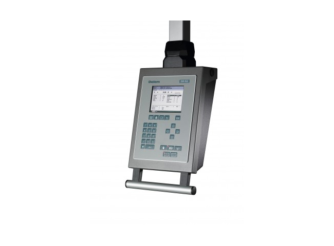
Панель управления на стойке ЧПУ, способна контролировать до 4 осей, а также приятный в использовании корпус с ручкой.
Данная система ЧПУ оснащена удобным пользовательским интерфейсом, DA-52 обеспечивает все основные функции листогибочного пресса.
Уникальная навигация горячими клавишами дает прямой доступ к программам в памяти и позволяет быстро и легко создавать программы и получать уже готовые изделия.
Все общие параметры изгиба расположены на одной странице. Для дополнительных настроек можно выбрать более подробный список параметров.
Угол программирования Y-оси, компенсация прогиба и контроль давления являются стандартными в этой системе.
USB-интерфейс позволяет использовать карты памяти (флеш карты), для быстрого резервного копирования программ продуктов и таблицы инструментов.
Delem DA-52s:
ЖК-дисплей с диагональю 6” в металлической раме, интерфейс на различных языках, память на 500 программ, на 30 комплектов инструмента, пуансон и матрица, программирование в один этап, компенсация изгибающего давления и деформаций рабочего стола, автоматический расчет изгибающего усилия нижней части, фнкция корректировки угла, независимая установка параметров материала, сохранение настроек после выключения питания.
ВИДЕО:
КОНСУЛЬТАЦИЯ:
СМОТРИТЕ ТАКЖЕ:
Preface
This manual contains information necessary for installation of a DA-52s control on a
pressbrake machine. It is meant for service people who are authorised for service and
installation of the machine.
Limited guarantee
•
The equipment is supplied by Delem without safety features. The machine manufacturer
has to ensure a safe environment.
•
This equipment must be installed and used in accordance with Delem’s specifications.
The guarantee on the equipment is invalidated in the event of improper installation and/or
use of this equipment.
•
The General Terms and Conditions of Delivery of Delem shall apply to this product.
These conditions are available from Delem on request.
•
This manual does not entitle you to any rights. Delem reserves the right to change this
manual without prior warning.
•
All rights reserved. The copyright is held by Delem. No part of this publication may be
copied or reproduced without written permission from Delem BV.
Version history
The control software is updated regularly to increase performance and add new functionality.
This manual is also updated as a result of changes in the control software. The following
overview shows the relation between software and manual versions.
Software version
V3
V3
V3
This manual is valid for software version 3.
Manual version
V0713
V0813
V0614
Description
first issue V3
update V3
update V3
Delem
V0614, 1.2
Delem DA-52s: Available Instructions
Note for Owners:
Guidesimo.com webproject is not a service center of Delem trademark and does not carries out works for diagnosis and repair of faulty Delem DA-52s equipment. For quality services, please contact an official service center of Delem company. On our website you can read and download documentation for your Delem DA-52s device for free and familiarize yourself with the technical specifications of device.
-
EuroLite Controller Pro
© Copyright Nachdruck verboten! Reproduction prohibited! Für weiteren Gebrauch aufbewahren! Keep this manual for future needs! BEDIENUNGSANLEITUNG USER MANUAL Controller Pro for LED Neon Flex 230V EC RGB …
Controller Pro Controller, 12
-
enphase BRK-100A-2P-240V
QUICK INSTALL GUIDE Model number: EP200G101-M240US01Install the Enphase IQ System Controller 2 To install the Enphase IQ System Controller 2 and the Enphase IQ System Controller 2 wall-mount bracket, read and follow all warnings and instructions in this guide and in the Enphase IQ System Controller 2 Installation and Operation Manual at enphase.com/support. Safety warnings are listed on the back …
BRK-100A-2P-240V Controller, 12
-
ILX Lightwave LDC-3900
User’s Guide Modular Laser Diode Controller LDC-3900 ILX Lightwave Corporation · P. O. Box 6310 · Bozeman, MT, U.S.A. 59771 · U.S. & Canada: 1-800-459-9459 · International Inquiries: 406-556-2481 · Fax 406-586-9405 ilx.custhelp.com · www.ilxlightwave.com 70011310 April 2010 …
LDC-3900 Controller, 4
-
Erbe VIO C
Fußschalter VIO C 3Footswitch VIO C 9Footswitch VIO C 15Interrupteur à pédale VIO C 21Interruptor de pedal VIO C 27Interruttore a pedale VIO C 33Interruptor de pedal VIO C 39Ποδοδιακόπτης VIO C 45Voetschakelaar VIO C 51Fodkontakt VIO C 57Pedal VIO C 63Jalkakytkin VIO C 69Przełącznik nożny VIO C 75Nožní spínač VIO C 81Lábkapcsoló VIO C 87Ножной переключате� …
VIO C Controller, 118
-
MCE Technologies iControl
Motion Control Engineering, Inc.11380 White Rock RoadRancho Cordova, CA 95742voice 916 463 9200fax 916 463 9201www.mceinc.comUser Guide,iControl with DC DriveRelease 3 SoftwareManual # 42-02-7223, Rev A3, December 2012 …
iControl Controller, 806
-
Fisher FIELDVUEDVC6200f
www.Fisher.comInstruction ManualD103412X012DVC6200f Digital Valve ControllerFebruary 20171Fisher™ FIELDVUE™ DVC6200f Digital ValveController for FOUNDATION™ FieldbusThis manual applies to:Device Type 4602Device Revision 4Hardware Revision 8, 9Firmware Revision 3.1DD Revision 3Instrument Level FD, PD, AD, PST …
FIELDVUEDVC6200f Controller, 352
-
S&C TripSaver II
June 22, 2020© S&C Electric Company 2018-2020, all rights reservedInstruction Sheet 461-509TripSaver® II Cutout-Mounted RecloserOutdoor Distribution (15.5 kV, 25 kV)TripSaver® II Communications via GatewayInstallation, Operation, and CongurationTable of ContentsSection Page Section PageIntroductionQualified Persons ……………………… 2Read this Instruction Sheet ……….. …
TripSaver II Control Unit, 63
-
Dungs FRM Series
Printed in Germany • 2015-10 • 270 455Mitteldruckregler FRMMedium Pressure Regulator FRMDirekt wirkendes Druckregelgerät nach EN 334 mit einstellbarer Sollwertfeder und modular anbaubarem Sicherheits-absperrventil nach EN 14382Direct acting pressure regulator with adjustable setpoint springs and modular mounted safety relief valve (SAV)In compliance with EN334 and EN14382 …
FRM Series Controller, 174
-
Holley 502-3
THROTTLE BODY P/N 502-3 (1985 1/2 – 89 GM Truck 2.8L V-6 Engine) 400 CFM P/N 502-4 (1986 – 89 GM Truck 4.3L V-6 Engine) 670 CFM P/ N 502-5 (1987 – 89 GM Truck 5.0L V-8 Engine) 670 CFM P/N 502-6 (1987 – 89 GM Truck 5.7L V-8 Engine) 670 CFM P/N 502-7 (1988 – 91 “S” & “T” Trucks 4.3L V-6 Engine) 670 CFM INSTALLATION & ADJUSTMENT INSTRUCTIONS INTRODUCTION Congratulation …
502-3 Controller, 4
Popular Controller User Guides:
DELEM DA-52 ЧПУ
Компактный DELEM DA-52 представляет собой комплексную систему ЧПУ как для обычных, так и синхронизированных листогибочных прессов.
Панель управления на стойке ЧПУ, способна контролировать до 4 осей, а также приятный в использовании корпус с ручкой.
Данная система ЧПУ оснащена удобным пользовательским интерфейсом, DA-52 обеспечивает все основные функции листогибочного пресса.
Уникальная навигация ‘горячими клавишами’ дает прямой доступ к программам в памяти и позволяет быстро и легко создавать программы и получать уже готовые изделия.
Все общие параметры изгиба расположены на одной странице. Для дополнительных настроек можно выбрать более подробный список параметров.
Угол программирования Y-оси, компенсация прогиба и контроль давления являются стандартными в этой системе.
USB-интерфейс позволяет использовать карты памяти (флешь карты), для быстрого резервного копирования программ продуктов и таблицы инструментов.
DA-52 основные особенности:
- Быстрое одностраничное программирование
- Клавиши навигации
- 6,4″ VGA цветной TFT
- До 4 осей (Y1, Y2, и 2 вспомогательные оси)
- Компенсация прогиба
- Библиотека: инструмента и материала
- USB интерфейс пооддерживает подключение периферийных устройств