- Manuals
- Brands
- Deutz Manuals
- Engine
- D 2011 w
- Workshop manual
-
Contents
-
Table of Contents
-
Bookmarks
Quick Links
Workshop Manual
competence level 2
D 2011 w
TD 2011 w, TCD 2011 w
0312 4176 en
.
This document is subject to changes which may become necessary in the course of further de-
velopment of the engines. Reprinting and reproductions of any kind, even in part, require our
written permission.
Related Manuals for Deutz TD 2011 w
Summary of Contents for Deutz TD 2011 w
-
Page 1
Workshop Manual competence level 2 D 2011 w TD 2011 w, TCD 2011 w 0312 4176 en This document is subject to changes which may become necessary in the course of further de- velopment of the engines. Reprinting and reproductions of any kind, even in part, require our… -
Page 2
Regarding copyright questions and licensing agreements please contact : TE-FI, Mr. Sonntag Tel.: + 49 (0) 221 822-3053 EMail: sonntag.j@deutz.com DEUTZ AG Sales & Service Information Systems Ottostraße 1 D-51149 Köln (Cologne) Phone.: +49 (0) 221-822-0 Fax: +49 (0) 221-822-3525 Internet: www.deutz.com… -
Page 3: Table Of Contents
DEUTZ engines Table of contents Foreword General User notes General Specifications Operating manual and workshop manual Job cards Explanation of symbols Technical data Testing and setting data Tightening specifications Job card overview Sorted alphabetically Sorted numerically Job cards Commercial tools Special tools ©…
-
Page 4
Table of contents DEUTZ engines © 06/2008 17761-001… -
Page 5: Foreword
DEUTZ engines Foreword Foreword © 05/2005 17762-001…
-
Page 6
Foreword DEUTZ engines © 05/2005 17762-001… -
Page 7
(use for the intended purpose). Any use above and beyond this is con- The engines made by DEUTZ are developed for sidered improper use. The manufacturer will not a wide range of applications. A wide range of var- be liable for damages resulting from this. -
Page 8
Foreword DEUTZ engines © 05/2005 17762-001… -
Page 9: General
DEUTZ engines General General © 11/2005 17763-001…
-
Page 10
General DEUTZ engines © 11/2005 17763-001… -
Page 11
DEUTZ engines General DEUTZ engines are the product of years of re- search and development. The profound expertise gained through this, in combination with high de- mands on quality, attests to the fact that our engines possess all the qualities of long life, high reliability and low fuel consumption. -
Page 12
General DEUTZ engines © 11/2005 17763-001… -
Page 13: User Notes
DEUTZ engines User notes User notes © 06/2008 17764-001…
-
Page 14
User notes DEUTZ engines © 06/2008 17764-001… -
Page 15
DEUTZ engines User notes 3.1 General 3.2 Specifications The documentation of the workshop manual has 3.2.1 Accident prevention and safety regu- been created based on the engine available at the lations time of going to press. The legally prescribed rules for the prevention of ac- There may be deviations in the descriptions, illustra- cidents must be observed. -
Page 16
Rail System Working materials and tools must be cleaned be- fore work. Only use tools without damage to the The DEUTZ Common Rail system used in the chrome plating or tools which are not chrome- DEUTZ engines consists of high-precision compo- plated. -
Page 17
DEUTZ engines User notes When removing and installing components, no operating materials among other things. The re- materials which can leave behind particles or fi- newed parts / operating materials must be stored, bres (cardboard, wood, cloths) may be used. -
Page 18
User notes DEUTZ engines 3.3 Operation manual and workshop 3.4 Job cards manual The job cards are divided in the workshop manual into «W» and «I» job cards. To structure the information to suit the user, the The «W» job card documents standard repairs on the service documentation is divided into operation engine and/or its components. -
Page 19: Explanation Of Symbols
Test and Setting Va- 8. Graphic or photo lues table. For example: 9. DEUTZ internal creation number ID no. P01 61 = valve clearance, inlet 10.Page number Tightening specification 11.Date of issue of job card The necessary values are specified here.
-
Page 20
User notes DEUTZ engines © 06/2008 17764-001… -
Page 21: Technical Data
D 2011 w Technical data TD 2011 w, TCD 2011 w Testing and setting data Technical data Testing and setting data © 12/2008 19484-001…
-
Page 22
Check after 15 minutes running P12 21 V-belt tension, individual V-belts AVX 10 −20 under load D 2011 w / TD 2011 w / TCD 2011 w Recess cylinder head Identification, cylinder head gas- P02 75 Piston overhang 9.820 — 10.140 mm… -
Page 23: Tightening Specifications
D 2011 w Technical data TD 2011 w, TCD 2011 w Tightening specifications Tightening specifications © 12/2008 19484-001…
-
Page 24
TD 2011 w, TCD 2011 w ID no. Name Screw type Notes / Remark Value D 2011 w / TD 2011 w / TCD 2011 w A00 001 Clamping bracket on crankcase 90 Nm Clamping bracket on adapter for A00 002 90 Nm… -
Page 25
D 2011 w Technical data TD 2011 w, TCD 2011 w Tightening specifications ID no. Name Screw type Notes / Remark Value M8x35-10.9 A09 010 Coolant pump on thermostat housing 20 Nm M8x100-10.9 A09 020 Pipe clip on holder M6x16… -
Page 26
8 Nm (exhaust gas return) 30IPR A07 087 Fuel filter console to crankcase 21 Nm TD 2011 w / TCD 2011 w A06 004 Pin bolts on exhaust pipe coated Use new pin bolts 12 Nm A06 020 Turbocharger on exhaust pipe… -
Page 27: Job Card Overview
D 2011 w TD 2011 w, TCD 2011 w Job card overview Job card overview Sorted alphabetically 1/12 © 12/2008 19488-001…
-
Page 28
Job card overview D 2011 w Sorted alphabetically TD 2011w, TCD 2011 w 2/12 © 12/2008 19488-001… -
Page 29
D 2011 w Job card overview TD 2011w, TCD 2011 w Sorted alphabetically Activity Job card Maintenance group Checking piston overhang W 01-04-09 Cylinder head Checking the compression pressure W 00-02-06 General Checking the thermostat (in the removed state) W 09-08-01 Cooling system Disassembling, assembling and checking the rocker arm and rocker arm… -
Page 30
Job card overview D 2011 w Sorted alphabetically TD 2011w, TCD 2011 w Activity Job card Maintenance group Removing and installing the oil filter console W 08-11-07 Lube oil system Removing and installing the oil pressure switch W 08-11-08 Lube oil system Removing and installing the rocker arm and rocker W 01-02-02 Cylinder head… -
Page 31: Sorted Numerically
D 2011 w Job card overview TD 2011 w, TCD 2011 w Sorted numerically Sorted numerically 5/12 © 12/2008 19488-001…
-
Page 32: Job Cards
Job card overview D 2011 w Sorted numerically TD 2011 w, TCD 2011 w 6/12 © 12/2008 19488-001…
-
Page 33
D 2011 w Job card overview TD 2011 w, TCD 2011 w Sorted numerically Job card Activity Maintenance group W 00-02-06 Checking the compression pressure General Mounting engine on assembly block and demoun- W 00-05-01 General ting W 01-01-01 Setting valve clearance… -
Page 34
Job card overview D 2011 w Sorted numerically TD 2011 w, TCD 2011 w Job card Activity Maintenance group W 09-08-01 Checking the thermostat (in the removed state) Cooling system W 09-08-02 Removing and installing the thermostat Cooling system W 09-08-04… -
Page 35
DEUTZ engines Job cards Job cards © 11/2005 17767-001… -
Page 36
Job cards DEUTZ engines © 11/2005 17767-001… -
Page 37: Special Tools
D 2011 w General TD 2011 w, TCD 2011 w W 00-02-06 Checking the compression pressure Commercial available tools: – W 01-01-01 – Compression pressure – W 07-07-01 tester……8005…
-
Page 38
General D 2011 w W 00-02-06 TD 2011 w, TCD 2011 w Mount clamping shoe (1). Tighten screw (2). 21 Nm © 47535-0 Connect adapter (1) to connector. © 47536-0 Mount the compression tester on the adapter. Turn over engine with starter. -
Page 39
D 2011 w General TD 2011 w, TCD 2011 w W 00-02-06 The measured compression pressure depends on the starting speed during the measuring process and the altitude of the Kompression in bar engine installation site. Therefore, limit Compression value in bar values cannot be determined exactly. -
Page 40
General D 2011 w W 00-02-06 TD 2011 w, TCD 2011 w Unscrew screw (1). © 47535-1 Remove connector (1). Remove sealing ring. Install fuel injectors. W 07-07-01 © 47534-1 © 12/2008 17768-001… -
Page 41
D 2011 w General TD 2011 w, TCD 2011 w W 00-02-06 Technical Data Testing and setting data ID no. Name Additional information Value 25 — 30 bar P00 51 Compression pressure (2500 — 3000 kPa) Tightening specifications ID no. -
Page 42
General D 2011 w W 00-02-06 TD 2011 w, TCD 2011 w © 12/2008 17768-001… -
Page 43
D 2011 w General TD 2011w, TCD 2011 w W 00-05-01 Mounting engine on assembly block and demounting Commercial available tools: – W 13-03-02 – Lifting gear – Suspension ropes – Eyelet bolts Danger! Special tools: When using hoists (workshop crane) the –… -
Page 44
D 2011 w W 00-05-01 TD 2011w, TCD 2011 w Unscrew screws (1). Remove all mounting feet. – TD 2011 w, TCD 2011 w Unscrew screw (2). Remove holder (3). Remove oil return pipe (4). © 47532-3 Mount clamping holder (1). -
Page 45
D 2011 w General TD 2011w, TCD 2011 w W 00-05-01 Unhook the engine from the workshop crane. Unscrew eyelet bolts (1). © 47538-0 Demounting engine from assembly block Screw in eyelet bolts (1). Hang engine on workshop crane. approx. 268 kg ©… -
Page 46
Mount oil return pipe (1). Attention! Install tension-free. Mount holder (2). Tighten screw (3). 8.5 Nm – D 2011 w, TD 2011 w, TCD 2011 w Install all mounting feet. Tighten screws (4). 200 Nm © 47532-4 © 12/2008 17769-001… -
Page 47
D 2011 w General TD 2011w, TCD 2011 w W 00-05-01 Danger! Put the engine down on a secure surface. Unhook the engine from the workshop crane. Unscrew eyelet bolts (1). Install starter. W 13-03-02 © 47538-0 © 12/2008 17769-001… -
Page 48
M14x55-12.9 A00 003 200 Nm crankcase M14x100-12.9 TD 2011 w, TCD 2011 w Torx, A08 049 Holder oil return line on crankcase 8.5 Nm M6x14-8.8 For the tightening procedure according to torque using a torque wrench, a maximum variation of the tightening torque of +/- 10% is permissible. -
Page 49: Setting Valve Clearance
D 2011 w Cylinder head TD 2011 w, TCD 2011 w W 01-01-01 Setting valve clearance Commercial available tools: Attention! – Feeler gauges In case of internal exhaust gas recircula- tion, the inlet valve is opened briefly by an additional cam on the camshaft.
-
Page 50
Cylinder head D 2011 w W 01-01-01 TD 2011 w, TCD 2011 w Arrangement of the inlet and exhaust val- ves. IN = inlet valve EX = exhaust valve Valve overlap means: The inlet valve starts opening,exhaust valve closes. Attention! -
Page 51
D 2011 w Cylinder head TD 2011 w, TCD 2011 w W 01-01-01 Check the valve clearance with feeler gauge (1). © 47543-1 Hold adjusting screw (2). Tighten lock nut (1). 20 Nm Do not turn the setting screw when tighte- ning the locking nut. -
Page 52
Cylinder head D 2011 w W 01-01-01 TD 2011 w, TCD 2011 w Valve clearance setting schematic According to the order given below, the setting of the valve clearance is possible in two turns of the crankshaft (each 360°). Crankshaft position 1 Turn over crankshaft until the valve overlap is achieved on cylinder 1. -
Page 53
D 2011 w Cylinder head TD 2011 w, TCD 2011 w W 01-01-01 Mount cylinder head cover. Oil the screws lightly. Tighten all screws (1) alternately. 8.5 Nm © 47540-1 © 12/2008 17770-001… -
Page 54
Cylinder head D 2011 w W 01-01-01 TD 2011 w, TCD 2011 w Technical Data Testing and setting data ID no. Name Additional information Value P00 71 Ignition sequence 1-3-4-2 P01 61 Valve clearance (inlet) 0.3 mm P01 62 Valve clearance (outlet) 0.5 mm… -
Page 55
D 2011 w Cylinder head TD 2011w, TCD 2011 w W 01-02-02 Removing and installing the rocker arm and rocker arm bracket Commercial available tools: – W 01-01-01 – Torx tool set ….8189 Removing the rocker arm and rocker arm bracket Unscrew all screws (1). -
Page 56
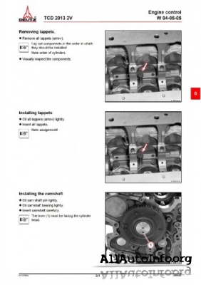
Cylinder head D 2011 w W 01-02-02 TD 2011w, TCD 2011 w Remove push rods (1). Lay out components in the order in which they should be installed. Visually inspect the components. © 47565-0 Installing the rocker arm and rocker arm bracket Insert stop rods (1). -
Page 57
D 2011 w Cylinder head TD 2011w, TCD 2011 w W 01-02-02 Lightly oil screws (1). Tighten screws . 21 Nm Attention! Makes sure that the stop rods are not under stress due to valve overlap when fastening the screws. Set valve clearance. -
Page 58
Cylinder head D 2011 w W 01-02-02 TD 2011w, TCD 2011 w Technical Data Tightening specifications ID no. Name Screw type Notes / Remark Value A01 002 Rocker arm bracket on cylinder head 21 Nm A01 004 Cylinder head cover on cylinder head 8.5 Nm For the tightening procedure according to torque using a torque wrench, a maximum variation of the tightening torque of +/- 10% is permissible. -
Page 59
D 2011 w Cylinder head TD 2011 w, TCD 2011 w W 01-02-06 Disassembling, assembling and checking the rocker arm and rocker arm bracket Commercial available tools: – W 01-02-02 – Internal measuring device – Micrometer gauge – Locking ring pliers Special tools: –… -
Page 60
Cylinder head D 2011 w W 01-02-06 TD 2011 w, TCD 2011 w Hold adjusting screw (2). Loosen lock nut (1). Unscrew adjusting screw (2). Lay out components in the order in which they should be installed. © 47031-0 Visually inspect the components. -
Page 61
D 2011 w Cylinder head TD 2011 w, TCD 2011 w W 01-02-06 Checking the rocker arm Prepare internal measuring device: – Mount probe bolt for the appropriate measuring range in the internal measuring device. – Mount dial gauge with approx. 1 mm pre-tension in the internal measuring device. -
Page 62
Cylinder head D 2011 w W 01-02-06 TD 2011 w, TCD 2011 w Assembling the rocker arm bracket Lightly oil the rocker arm pin. Push rocker arm (1) onto rocker arm pin. © 39149-2 Insert new locking rings (1). Ensure that the installation location is free from faults. -
Page 63
D 2011 w Cylinder head TD 2011 w, TCD 2011 w W 01-02-06 Technical Data Testing and setting data ID no. Name Additional information Value +0.27 P01 72 Rocker arm, bore, diameter (outlet) +0.27 P01 73 Rocker arm, bore, diameter (inlet) +0.01… -
Page 64
Cylinder head D 2011 w W 01-02-06 TD 2011 w, TCD 2011 w © 12/2008 17772-001… -
Page 65
– W 06-02-03 … . TD 2011 w, – Dog wrench….8018 TCD 2011 w –… -
Page 66
Unscrew lock nuts (1) with dog wrench. Remove thermostat housing. W 09-08-04 – D 2011 w Remove the air intake pipe. W 06-07-03 – TD 2011 w, TCD 2011 w Remove the charge air pipe. W 06-02-03 Remove exhaust gas collection pipe. W 06-09-08 © 47550-0 Remove rocker arm and rocker arm bracket. -
Page 67
D 2011 w Cylinder head TD 2011 w, TCD 2011 w W 01-04-04 Installing the cylinder head Measure the piston overhang on all pistons. Select cylinder head gasket according to the largest piston projection measured. Check piston overhang. W 01-04-09 ©… -
Page 68
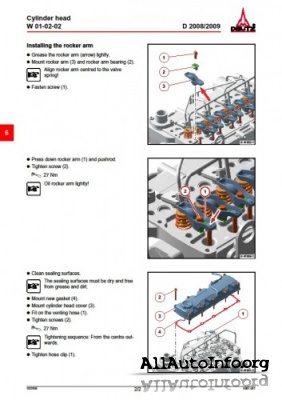
Cylinder head D 2011 w W 01-04-04 TD 2011 w, TCD 2011 w Clean sealing surfaces. The sealing surfaces for the cylinder head gasket must be clean and free of oil. Make sure the clamping bushings (1) are in place. -
Page 69
Install rocker arm and rocker arm bracket. W 01-02-02 – D 2011 w Install the air intake pipe. W 06-07-03 – TD 2011 w, TCD 2011 w Install the charge air pipe. W 06-02-03 © 47547-0 Install exhaust gas collection pipe. -
Page 70
Cylinder head D 2011 w W 01-04-04 TD 2011 w, TCD 2011 w Position clamping claws (1). Attention! Install tension-free. Tighten screws (2). 21 Nm © 47551-0 © 12/2008 17773-001… -
Page 71
D 2011 w Cylinder head TD 2011 w, TCD 2011 w W 01-04-04 Technical Data Testing and setting data ID no. Name Additional information Value Identification, cylinder head gasket P02 75 Piston overhang 0.325 — 0.604 mm = 1 recess… -
Page 72
Cylinder head D 2011 w W 01-04-04 TD 2011 w, TCD 2011 w © 12/2008 17773-001… -
Page 73
D 2011 w Cylinder head TD 2011 w, TCD 2011 w W 01-04-09 Checking piston overhang Commercial available tools – W 01-04-04 8190 Special tools: – Dial gauge….100400 –… -
Page 74
Cylinder head D 2011 w W 01-04-09 TD 2011 w, TCD 2011 w – Recess cylinder head Insert dial gauge 100410 in measuring beam. Place holders (1) on the sealing surface of the crank- case. Place measuring beam (2) on the holders. -
Page 75
D 2011 w Cylinder head TD 2011 w, TCD 2011 w W 01-04-09 – Recess cylinder head Move the measuring beam. Apply the stylus to the piston base (arrow) under pre- tension. Continue turning the crankshaft evenly until the re- versal point of the pointer on the dial gauge is reached. -
Page 76
Cylinder head D 2011 w W 01-04-09 TD 2011 w, TCD 2011 w – Recess cylinder head Select cylinder head gasket according to the largest piston projection measured. – 1 recess 9.820 — 10.140 mm – 2 recesses 10.141 — 10.239 mm –… -
Page 77
Identification, cylinder head gasket P02 77 Piston overhang 0.705 — 0.804 mm = 3 recesses D 2011 w / TD 2011 w / TCD 2011 w Recess cylinder head Identification, cylinder head gasket P02 75 Piston overhang 9.820 — 10.140 mm… -
Page 78
Cylinder head D 2011 w W 01-04-09 TD 2011 w, TCD 2011 w © 12/2008 17774-001… -
Page 79
D 2011 w Crankcase TD 2011 w, TCD 2011 w W 03-01-11 Removing and installing the crankcase bleeding Commercial available tools Special tools: – Disassembly tool… . . 110901 Removing the crankcase bleeding Unscrew screw (1). -
Page 80
Crankcase D 2011 w W 03-01-11 TD 2011 w, TCD 2011 w Install crankcase bleeding Clean sealing surfaces. Insert new O-ring (1). © 47160-0 Mount crankcase vent (2). Ensure that the installation location is free from faults. The crankcase bleeding must fit evenly. -
Page 81
D 2011 w Crankcase TD 2011 w, TCD 2011 w W 03-01-11 Technical Data Tightening specifications ID no. Name Screw type Notes / Remark Value Crankcase bleeding on front cover / A03 060 on cylinder head cover / on cylinder 8.5 Nm… -
Page 82
Crankcase D 2011 w W 03-01-11 TD 2011 w, TCD 2011 w © 12/2008 17790-001… -
Page 83
W 06-06-04 – Torx tool set ….8189 Removing exhaust line – TD 2011 w, TCD 2011 w Remove turbocharger. W 06-06-04 Unscrew all screws (1). -
Page 84
Clean sealing surfaces. Mount exhaust line (1). Mount new gaskets. Note installation position. Turn in new screws (2). Tighten new screws (2). 55 Nm – TD 2011 w, TCD 2011 w Install the turbocharger. W 06-06-04 © 47523-2 © 12/2008 17805-001… -
Page 85
D 2011 w Exhaust system/Charging TD 2011 w, TCD 2011 w W 06-01-05 Technical Data Tightening specifications ID no. Name Screw type Notes / Remark Value Torx screw, A06 001 Exhaust pipe at cylinder head Use new screws. 55 Nm… -
Page 86
Exhaust system/Charging D 2011 w W 06-01-05 TD 2011 w, TCD 2011 w © 12/2008 17805-001… -
Page 87
Exhaust system/Charging TD 2011 w, TCD 2011 w W 06-02-03 Removing and install the charge air line Commercial available tools: – W 06-06-04 – Torx tool set ….8189 –… -
Page 88
Exhaust system/Charging W 06-02-03 TD 2011 w, TCD 2011 w Install charge air line Mount charge air line (1). Mount new gaskets. Tighten screws (2) alternately working from the cen- tre to the outside. 21 Nm Install the exhaust pipe. -
Page 89
Exhaust system/Charging TD 2011 w, TCD 2011 w W 06-02-03 Technical Data Tightening specifications ID no. Name Screw type Notes / Remark Value Torx screw, A06 030 Charge air pipe on cylinder head Use new screws. 21 Nm coated For the tightening procedure according to torque using a torque wrench, a maximum variation of the tightening torque of +/- 10% is permissible. -
Page 90
Exhaust system/Charging W 06-02-03 TD 2011 w, TCD 2011 w © 12/2008 17806-001… -
Page 91
Exhaust system/Charging TD 2011 w, TCD 2011 w W 06-06-04 Removing and installing the turbocharger Commercial available tools: Attention! – Clamping tongs….9088 Do not remove the stoppers/caps until –… -
Page 92
Exhaust system/Charging W 06-06-04 TD 2011 w, TCD 2011 w Loosen spring band clip (1) with spring band pliers. Remove reducer (2). © 47554-0 Unscrew hollow screw (1). Remove lubricating oil pipe (2). Remove sealing rings. Press in stoppers. © 47526-0 Loosen spring band clip (1) with spring band pliers. -
Page 93
Exhaust system/Charging TD 2011 w, TCD 2011 w W 06-06-04 Unscrew nuts (1). © 47528-0 Remove turbocharger in the direction of the arrow. Remove gasket (1). © 47555-0 Remove the O-ring (1) with the disassembly tool. Unscrew screw-in nipple (2). -
Page 94
Exhaust system/Charging W 06-06-04 TD 2011 w, TCD 2011 w Unscrew studs (1). Check components for visible signs of wear. © 47523-0 Installing the turbocharger Mount sealing ring (1). Tighten screw-in nipple (2). 40 Nm Insert new O-ring (3). © 47529-1 Clean sealing surfaces. -
Page 95
Exhaust system/Charging TD 2011 w, TCD 2011 w W 06-06-04 Mount gasket (1). Plug in the tubing connection (2). Insert turbocharger in the direction of the arrow. © 47555-1 Mount turbocharger (1). Turn on new nuts (2). Tighten nuts (2). -
Page 96
Exhaust system/Charging W 06-06-04 TD 2011 w, TCD 2011 w Mount lubrication oil line (1). Mount sealing rings (2). Screw on hollow screw (3). © 47526-1 Insert new O-ring (1). Lightly oil new O-ring (1). © 39378-2 Mount oil return pipe (1). -
Page 97
Exhaust system/Charging TD 2011 w, TCD 2011 w W 06-06-04 Attention! Install tension-free. Tighten hollow screw (1). 29 Nm © 47526-2 Mount the reducer (1). Attention! Install tension-free. Position spring band clip (2) with spring band pliers. © 47554-1 Position hose clip (1) with clamping tongs. -
Page 98
Exhaust system/Charging W 06-06-04 TD 2011 w, TCD 2011 w Technical Data Tightening specifications ID no. Name Screw type Notes / Remark Value A06 004 Pin bolts on exhaust pipe coated Use new pin bolts 12 Nm A06 020 Turbocharger on exhaust pipe… -
Page 99
Exhaust system/Charging D 2011 w W 06-07-03 Removing and installing the intake manifold Commercial available tools: – W 06-01-05 – Torx tool set ….8189 Removing the intake manifold Remove the exhaust pipe. -
Page 100
Exhaust system/Charging W 06-07-03 D 2011 w Installing the intake manifold Mount new gaskets. Mount intake manifold (1). Tighten new screws (2) alternately working from the centre to the outside. 21 Nm Install the exhaust pipe. W 06-01-05 © 47645-1 ©… -
Page 101
Exhaust system/Charging D 2011 w W 06-07-03 Technical Data Tightening specifications ID no. Name Screw type Notes / Remark Value Air suction intake pipe on cylinder Torx screw, A06 030 Use new screws. 21 Nm head coated For the tightening procedure according to torque using a torque wrench, a maximum variation of the tightening torque of +/- 10% is permissible. -
Page 102
Exhaust system/Charging W 06-07-03 D 2011 w © 12/2008 17808-001… -
Page 103
Exhaust system/Charging D 2011 w W 06-09-06 Removing and installing the exhaust gas return valve Commercial available tools: – Special bit, 70 mm long..9120 Removing the exhaust gas return valve Unscrew screw (1) with special bit. -
Page 104
Exhaust system/Charging W 06-09-06 D 2011 w Unscrew hollow screws (1). Remove pipe (2). Remove sealing rings (3). © 46935-0 Unscrew hollow screw (1). Remove sealing rings (2). Unscrew hollow screw (3). Remove sealing rings (4). Remove pipe (5). © 46938-0 Unscrew screws (1). -
Page 105
Exhaust system/Charging D 2011 w W 06-09-06 Remove gasket (1). © 46940-0 Unscrew screws (1). Remove the exhaust gas return valve. © 46941-0 Remove gasket (1). © 46942-0 © 12/2008 17809-001… -
Page 106
Exhaust system/Charging W 06-09-06 D 2011 w Visually inspect the components. © 46965-0 Installing the exhaust gas return valve Clean sealing surfaces. Mount gasket (1). Mount exhaust gas return valve (2). © 46943-0 Tighten screws (1). Tighten screws (1). 20 Nm ©… -
Page 107
Exhaust system/Charging D 2011 w W 06-09-06 Clean sealing surfaces. Mount gasket (1). Mount exhaust gas collection pipe (2). Fasten screws (3). Tighten screws (3). 20 Nm © 46939-1 Insert pipe (5). Mount new sealing rings (4). Screw on hollow screw (3). Mount sealing rings (2). -
Page 108
Exhaust system/Charging W 06-09-06 D 2011 w Press in pipe holder (1). © 46937-0 Plug in the cable plug (3). Mount the safety cover (2). Fasten screw (1). Tighten screw (1) with special bit. 8 Nm © 46964-0 © 12/2008 17809-001… -
Page 109
Exhaust system/Charging D 2011 w W 06-09-06 Technical Data Tightening specifications ID no. Name Screw type Notes / Remark Value Pipe to exhaust gas return valve/cylin- Hollow screw A06 057 29 Nm der head (cooling — intake) M12x1.5 Exhaust return pipe to exhaust return A06 062 M8x65-10.9 20 Nm… -
Page 110
Exhaust system/Charging W 06-09-06 D 2011 w © 12/2008 17809-001… -
Page 111
Exhaust system/Charging D 2011 w W 06-09-07 Removing and installing the exhaust gas return pipe Commercial available tools: – Special bit, 70 mm long..9120 Removing the exhaust gas return pipe Unscrew screw (1). -
Page 112
Exhaust system/Charging W 06-09-07 D 2011 w Unscrew hollow screws (1). Remove pipe (2). Remove sealing rings (3). © 46935-0 Unscrew hollow screw (1). Remove sealing rings (2). Unscrew hollow screw (3). Remove sealing rings (4). Remove pipe (5). © 46938-0 Unscrew screws (1). -
Page 113
Exhaust system/Charging D 2011 w W 06-09-07 Remove gasket (1). © 46940-0 Unscrew screws (1). Remove the exhaust return pipe. © 46961-0 Remove gasket (1). © 46962-0 © 12/2008 17810-001… -
Page 114
Exhaust system/Charging W 06-09-07 D 2011 w Unscrew screws (3). Remove exhaust gas return valve (2). Remove gasket (1). © 46960-0 Visually inspect the components. © 46963-0 Installing the exhaust gas return pipe Clean all sealing surfaces. Mount gasket (1). Mount exhaust gas return valve (2). -
Page 115
Exhaust system/Charging D 2011 w W 06-09-07 Clean all sealing surfaces. Mount gasket (1). © 46962-0 Install the exhaust gas return pipe. Tighten screws (1). Tighten screws (1). 8.5 Nm © 46961-0 Clean sealing surfaces. Mount gasket (1). Mount exhaust gas collection pipe (2). Fasten screws (3). -
Page 116
Exhaust system/Charging W 06-09-07 D 2011 w Insert pipe (5). Mount new sealing rings (4). Screw on hollow screw (3). Mount sealing rings (2). Tighten hollow screw (1). 29 Nm Tighten hollow screw (3). 12 Nm © 46938-0 Insert pipe (1). Mount sealing rings (2). -
Page 117
Exhaust system/Charging D 2011 w W 06-09-07 Plug in the cable plug (3). Mount the safety cover (2). Fasten screw (1). Tighten screw (1). 8 Nm © 46964-0 © 12/2008 17810-001… -
Page 118
Exhaust system/Charging W 06-09-07 D 2011 w Technical Data Tightening specifications ID no. Name Screw type Notes / Remark Value Pipe to exhaust gas return valve/cylin- Hollow screw A06 057 29 Nm der head (cooling — intake) M12x1.5 Exhaust return pipe to exhaust return A06 062 M8x65-10.9 20 Nm… -
Page 119: Exhaust Gas Recirculation
Exhaust system/Charging D 2011 w W 06-09-08 Removing and installing the exhaust gas collection pipe (Exhaust gas recirculation) Commercial available tools: – W 06-01-05 – Cleaning brush ….8167 –…
-
Page 120
Exhaust system/Charging W 06-09-08 D 2011 w Remove gaskets (1). © 46948-0 Clean exhaust channels (1) with cleaning brush (2). Clean all sealing surfaces. © 46949-0 Install exhaust gas collection pipe Check that mounting lugs (1) are sufficiently pre-ten- sioned. ©… -
Page 121
Exhaust system/Charging D 2011 w W 06-09-08 Mount gasket (1). Make sure that the installation site of the mounting lugs (2) is in perfect condition. © 46951-0 Mount new gaskets (3). Mount new throttle (2). Note installation position. The marking (arrow) on the throttle is dependent on the engine version. -
Page 122
Exhaust system/Charging W 06-09-08 D 2011 w Tighten new screws (1). 55 Nm Install the exhaust gas return pipe. W 06-09-07 Install the exhaust pipe. W 06-01-05 © 46947-0 © 12/2008 17811-001… -
Page 123
Exhaust system/Charging D 2011 w W 06-09-08 Technical Data Tightening specifications ID no. Name Screw type Notes / Remark Value Torx M10x25-10.9 Exhaust gas collection pipe (exhaust Torx A06 073 Use new screws. 55 Nm gas return) on cylinder head M10x30-10.9 Torx M10x45-10.9… -
Page 124
Exhaust system/Charging W 06-09-08 D 2011 w © 12/2008 17811-001… -
Page 125
D 2011 w Fuel system TD 2011 w, TCD 2011 w W 07-02-07 Removing and installing the lifting magnet (Start amount release) Commercial available tools: Collect leaking operating substances in – Plier insert….8027 suitable vessels and dispose of according to regulations. -
Page 126
Fuel system D 2011 w W 07-02-07 TD 2011 w, TCD 2011 w Remove the O-ring (1) with the disassembly tool. Visually inspect the components. © 47392-0 Install lifting magnet Insert new O-ring (1). © 47392-0 Clean all sealing surfaces. -
Page 127
D 2011 w Fuel system TD 2011 w, TCD 2011 w W 07-02-07 Tighten lifting magnet (1) with plier insert. 10 Nm Note direction of terminal. © 39664-1 Plug in the cable plug (1). © 47128-0 © 12/2008 17814-001… -
Page 128
Fuel system D 2011 w W 07-02-07 TD 2011 w, TCD 2011 w Technical Data Tightening specifications ID no. Name Screw type Notes / Remark Value Lifting magnet (start amount release) A05 065 10 Nm on front cover For the tightening procedure according to torque using a torque wrench, a maximum variation of the tightening torque of +/- 10% is permissible. -
Page 129
D 2011 w Fuel system TD 2011 w, TCD 2011 w W 07-03-01 Renewing the injection lines Commercial available tools: Danger! – Dog wrench….8018… -
Page 130
Fuel system D 2011 w W 07-03-01 TD 2011 w, TCD 2011 w Remove injection pipes (1). Lay out components in the order in which they should be installed. Note assignment! © 47652-0 Mount the caps (1). © 47654-0 Visually inspect the components. -
Page 131
D 2011 w Fuel system TD 2011 w, TCD 2011 w W 07-03-01 Installing injection pipes Pull off the caps (1). Mount new injection pipe. © 47654-0 Screw on union nuts (1). Attention! Install injection line without tension. Note installation position. -
Page 132
Fuel system D 2011 w W 07-03-01 TD 2011 w, TCD 2011 w Technical Data Tightening specifications ID no. Name Screw type Notes / Remark Value Injection line on fuel injector / injection A07 003 M12x1.5 25 Nm pump For the tightening procedure according to torque using a torque wrench, a maximum variation of the tightening torque of +/- 10% is permissible. -
Page 133
D 2011 w Fuel system TD 2011 w, TCD 2011 w W 07-07-01 Removing and installing the fuel injectors Commercial available tools: – W 07-03-01 – Assembly pliers….8024 –… -
Page 134
Fuel system D 2011 w W 07-07-01 TD 2011 w, TCD 2011 w Unscrew screw (1). Remove clamping shoe (2). © 47562-0 Pull out fuel injector (1) and sealing ring (arrow). Lay out components in the order in which they should be installed. -
Page 135
D 2011 w Fuel system TD 2011 w, TCD 2011 w W 07-07-01 Mount sliding hammer on fuel injector. Screw on lock nut (1). Pull out stuck fuel injector. © 47564-0 Grip a tight sealing ring (1) with the assembly pliers (2) and pull off, turning slightly. -
Page 136
Fuel system D 2011 w W 07-07-01 TD 2011 w, TCD 2011 w Installing the fuel injector Mount new sealing ring (1) on fuel injector. © 47351-0 Insert fuel injector. Mount clamping shoe. Note installation position of the clamping shoe. -
Page 137
D 2011 w Fuel system TD 2011 w, TCD 2011 w W 07-07-01 Install injection lines. W 07-03-01 © 47557-0 © 12/2008 19502-001… -
Page 138
Fuel system D 2011 w W 07-07-01 TD 2011 w, TCD 2011 w Technical Data Tightening specifications ID no. Name Screw type Notes / Remark Value A07 001 Fuel injector on cylinder head 21 Nm For the tightening procedure according to torque using a torque wrench, a maximum variation of the tightening torque of +/- 10% is permissible. -
Page 139
Fuel system TD 2011 w, TCD 2011 w W 07-08-01 Removing and installing the lifting magnet (charge air pressure-dependent full load stop) Commercial available tools: – Plier insert….8027 Special tools: –… -
Page 140
Fuel system W 07-08-01 TD 2011 w, TCD 2011 w Install lifting magnet Mount new O-ring. Insert lifting magnet (1). © 47648-0 Tighten lifting magnet (1) with plier insert. 10 Nm © 47646-0 © 12/2008 17821-001… -
Page 141
Fuel system TD 2011 w, TCD 2011 w W 07-08-01 Technical Data Tightening specifications ID no. Name Screw type Notes / Remark Value A06 094 Lifting magnet on fuel filter console Renew O-ring 10 Nm For the tightening procedure according to torque using a torque wrench, a maximum variation of the tightening torque of +/- 10% is permissible. -
Page 142
Fuel system W 07-08-01 TD 2011 w, TCD 2011 w © 12/2008 17821-001… -
Page 143
Fuel system TD 2011 w, TCD 2011 w W 07-08-02 Installing and removing charge air pressure-dependent full load stop Commercial available tools: – W 07-10-08 – Plier insert….8027 Special tools: –… -
Page 144
Fuel system W 07-08-02 TD 2011 w, TCD 2011 w Unscrew lifting magnet (1) with plier insert. © 39387-1 Remove the O-ring with the disassembly tool. Visually inspect the components. © 47647-0 Installing the charge air-pressure depend- ent full load stop Clean sealing surfaces. -
Page 145
Fuel system TD 2011 w, TCD 2011 w W 07-08-02 Insert spring (1). Insert diaphragm (2) and cap (3). Attention! Note installation position. © 39389-1 Tighten screws (1). 8 Nm Install the fuel filter console. W 07-10-08 © 39385-2 © 12/2008… -
Page 146
Fuel system W 07-08-02 TD 2011 w, TCD 2011 w Technical Data Tightening specifications ID no. Name Screw type Notes / Remark Value A06 094 Lifting magnet on fuel filter console Renew O-ring 10 Nm Cap on charge air-dependent full load… -
Page 147
D 2011 w Fuel system TD 2011 w, TCD 2011 w W 07-10-06 Removing and installing fuel pipes Commercial available tools: Danger! – Hose clip pliers ….8011 Wait 30 seconds after switching off the –… -
Page 148
Fuel system D 2011 w W 07-10-06 TD 2011 w, TCD 2011 w Loosen spring band clips (1) with spring band pliers. © 47572-0 Pull off hose pieces (1) in the direction of the arrow. © 47573-0 Loosen hose clip (1). -
Page 149
D 2011 w Fuel system TD 2011 w, TCD 2011 w W 07-10-06 Loosen hose clip (1). Pull off fuel pipe (2). Collect draining fuel and dispose of accor- ding to regulations. © 47614-0 Unscrew hollow screws (1). Remove fuel pipe (2). -
Page 150
Fuel system D 2011 w W 07-10-06 TD 2011 w, TCD 2011 w Visually inspect the components. © 47618-0 Installing fuel pipes Mount fuel return pipe (1). Mount sealing rings (2). Tighten hollow screw (3). 29 Nm © 47617-1 Mount fuel pipe (1). -
Page 151
D 2011 w Fuel system TD 2011 w, TCD 2011 w W 07-10-06 Mount fuel hose (2). Lay hose without contact. Ensure that the installation location is free from faults. Mount new hose clip (1). Fix the hose clip (1) with the hose clip pliers. -
Page 152
Fuel system D 2011 w W 07-10-06 TD 2011 w, TCD 2011 w Push on hose pieces (1) in the direction of the arrow. © 47573-1 Position spring band clips (1) with spring band pliers. © 47572-0 Position clamping claws (1). -
Page 153
D 2011 w Fuel system TD 2011 w, TCD 2011 w W 07-10-06 Technical Data Tightening specifications ID no. Name Screw type Notes / Remark Value A07 015 Fuel supply line to injection pump Hollow screw Replace sealing rings 29 Nm… -
Page 154
Fuel system D 2011 w W 07-10-06 TD 2011 w, TCD 2011 w © 12/2008 17823-001… -
Page 155
Fuel system TD 2011 w, TCD 2011 w W 07-10-08 Removing and installing the fuel filter console Commercial available tools: Danger! – Hose clip pliers ….8011 Wait 30 seconds after switching off the –… -
Page 156
Fuel system W 07-10-08 TD 2011 w, TCD 2011 w Pull off hose pipe (1). © 47593-0 Unscrew screws (1). Remove fuel filter console (2). © 47594-0 Remove the O-ring (1) with the disassembly tool. © 47595-0 © 12/2008 17824-001… -
Page 157
Fuel system TD 2011 w, TCD 2011 w W 07-10-08 Visually inspect the components. © 47596-0 Installing the fuel filter console Clean sealing surfaces. © 47597-0 Insert new sealing ring (1). © 47598-0 © 12/2008 17824-001… -
Page 158
Fuel system W 07-10-08 TD 2011 w, TCD 2011 w Install the fuel filter console (2). Tighten screws (1). 22 Nm © 47594-0 Mount the hose pipe (1). © 47593-0 Note assignment! Lay hoses without contact. Install fuel hoses. Mount new hose clips (1). -
Page 159
Fuel system TD 2011 w, TCD 2011 w W 07-10-08 Position protective hoses, dimension X. 20 mm © 47599-0 © 12/2008 17824-001… -
Page 160
Fuel system W 07-10-08 TD 2011 w, TCD 2011 w Technical Data Tightening specifications ID no. Name Screw type Notes / Remark Value Fuel filter console/full load stop to Torx, A07 087 22 Nm crankcase M8x50-8.8 For the tightening procedure according to torque using a torque wrench, a maximum variation of the tightening torque of +/- 10% is permissible. -
Page 161
D 2011 w Fuel system TD 2011 w, TCD 2011 w W 07-11-01 Removing and installing the fuel supply pump Commercial available tools: Danger! – Hose clip pliers ….8011… -
Page 162
Fuel system D 2011 w W 07-11-01 TD 2011 w, TCD 2011 w Loosen hose clip (1). Pull off fuel pipe (2). Pull off protective hose (3). Collect draining fuel and dispose of accor- ding to regulations. © 47610-0 Unscrew screws (1). -
Page 163
D 2011 w Fuel system TD 2011 w, TCD 2011 w W 07-11-01 Installing the fuel supply pump Turn the crankshaft until the eccentric of the cam- shafts is in the top dead centre (arrow). © 47398-0 Insert new O-ring (1). -
Page 164
Fuel system D 2011 w W 07-11-01 TD 2011 w, TCD 2011 w Slip protective hose (3) over with mounting com- pound. Lay hose without contact. Mount fuel hose (2). Mount new hose clip (1). © 47610-0 Position protective hose, dimension X. -
Page 165
D 2011 w Fuel system TD 2011 w, TCD 2011 w W 07-11-01 Insert oil dipstick (1). © 47608-0 © 12/2008 17825-001… -
Page 166
Fuel system D 2011 w W 07-11-01 TD 2011 w, TCD 2011 w Technical Data Tightening specifications ID no. Name Screw type Notes / Remark Value A07 024 Fuel supply pump on crankcase 21 Nm For the tightening procedure according to torque using a torque wrench, a maximum variation of the tightening torque of +/- 10% is permissible. -
Page 167
D 2011 w Lube oil system TD 2011 w, TCD 2011 w W 08-08-02 Removing and installing the lubricating oil cooler Commercial available tools – W 08-11-07 Collect leaking operating substances in suitable vessels and dispose of according to regulations. -
Page 168
Lube oil system D 2011 w W 08-08-02 TD 2011 w, TCD 2011 w Installing the lubricating oil cooler Visually inspect the components. © 47519-0 Clean sealing surfaces. Insert new sealing ring (1). © 47518-0 Mount lubricating oil cooler (1). -
Page 169
D 2011 w Lube oil system TD 2011 w, TCD 2011 w W 08-08-02 Technical Data Tightening specifications ID no. Name Screw type Notes / Remark Value Lubricating oil cooler on oil filter con- A08 051 M6x16-10.9 13 Nm sole For the tightening procedure according to torque using a torque wrench, a maximum variation of the tightening torque of +/- 10% is permissible. -
Page 170
Lube oil system D 2011 w W 08-08-02 TD 2011 w, TCD 2011 w © 12/2008 17829-001… -
Page 171
D 2011 w Lube oil system TD 2011 w, TCD 2011 w W 08-11-07 Removing and installing the oil filter console Commercial available tools: – Operation manual – Torx tool set ….8189 –… -
Page 172
Lube oil system D 2011 w W 08-11-07 TD 2011 w, TCD 2011 w Unscrew hollow screw (1). Remove sealing rings (2). © 47514-0 Unscrew lubricating oil filter (1) with special wrench. Collect draining lubricating oil and dispose of properly. -
Page 173
D 2011 w Lube oil system TD 2011 w, TCD 2011 w W 08-11-07 Remove gasket (1). Clean sealing surfaces. © 47520-0 Installing oil filter console Visually inspect the components. © 47521-0 Fix new gasket (1) to the crankcase with a little grease. -
Page 174
Lube oil system D 2011 w W 08-11-07 TD 2011 w, TCD 2011 w Mount oil filter console (1). Do not move gasket. Tighten screws (2). Turn in screw (3). Tighten screws (2). 21 Nm Tighten screw (3). 21 Nm ©… -
Page 175
D 2011 w Lube oil system TD 2011 w, TCD 2011 w W 08-11-07 Push on hose pieces (1) in the direction of the arrow. © 47573-1 Position the spring band clip (1) with the spring band pliers. © 47572-0 ©… -
Page 176
Lube oil system D 2011 w W 08-11-07 TD 2011 w, TCD 2011 w Technical Data Tightening specifications ID no. Name Screw type Notes / Remark Value Torx M8x50-8.8 A08 003 Oil filter console on crankcase 21 Nm Torx M8x90-8.8… -
Page 177
D 2011 w Lube oil system TD 2011 w, TCD 2011 w W 08-11-08 Removing and installing the oil pressure switch Commercial available tools Collect leaking operating substances in suitable vessels and dispose of according to regulations. Removing the oil pressure switch Pull out cable plug (1). -
Page 178
Lube oil system D 2011 w W 08-11-08 TD 2011 w, TCD 2011 w Visually inspect the components. © 47433-0 Installing the oil pressure switch Screw on oil pressure switch (1). © 47434-0 Tighten oil pressure switch (1). 13 Nm ©… -
Page 179
D 2011 w Lube oil system TD 2011 w, TCD 2011 w W 08-11-08 Plug in the cable plug (1). Ensure that the connection is perfect. © 47344-0 © 12/2008 17832-001… -
Page 180
Lube oil system D 2011 w W 08-11-08 TD 2011 w, TCD 2011 w Technical Data Tightening specifications ID no. Name Screw type Notes / Remark Value A08 091 Oil pressure switch on crankcase M10x1 13 Nm For the tightening procedure according to torque using a torque wrench, a maximum variation of the tightening torque of +/- 10% is permissible. -
Page 181
D 2011 w Lube oil system TD 2011 w, TCD 2011 w W 08-11-12 Removing and installing the thermostat (Lubricating oil cooler) Commercial available tools: Collect leaking operating substances in – Slide gauge suitable vessels and dispose of according – Torx tool set ….8189 to regulations. -
Page 182
Lube oil system D 2011 w W 08-11-12 TD 2011 w, TCD 2011 w Remove the O-ring (1) with the disassembly tool. © 47439-0 Visually inspect the components. © 47568-0 Installing the thermostat Measure length of the compressor spring with calli- per gauge. -
Page 183
D 2011 w Lube oil system TD 2011 w, TCD 2011 w W 08-11-12 Clean sealing surfaces. Oil the thermostat lightly. Insert compression spring. Insert thermostat (1). Note installation position. © 47575-0 Lightly oil new O-ring (1). Insert new O-ring (1). -
Page 184
Lube oil system D 2011 w W 08-11-12 TD 2011 w, TCD 2011 w Technical Data Testing and setting data ID no. Name Additional information Value P08 74 Thermostat, compression spring, length 45.7 mm Tightening specifications ID no. Name Screw type Notes / Remark… -
Page 185
D 2011 w Lube oil system TD 2011 w, TCD 2011 w W 08-16-01 Removing and installing the control line Commercial available tools – W 07-10-08 – W 08-11-07 Collect leaking operating substances in suitable vessels and dispose of according to regulations. -
Page 186
Lube oil system D 2011 w W 08-16-01 TD 2011 w, TCD 2011 w Visually inspect sealing surfaces (arrows). © 47651-0 Visually inspect the components. © 47649-0 Installing control line Insert control line (1). Mount sealing rings (2). Screw in all hollow screws. -
Page 187
D 2011 w Lube oil system TD 2011 w, TCD 2011 w W 08-16-01 Install the fuel filter console. W 07-10-08 Mount oil filter console. W 08-11-07 Insert control line (1). Mount sealing rings (2). Tighten hollow screw (3). 18 Nm ©… -
Page 188
Lube oil system D 2011 w W 08-16-01 TD 2011 w, TCD 2011 w Technical Data Tightening specifications ID no. Name Screw type Notes / Remark Value Control line to oil filter console / crank- Hollow screw A08 048 18 Nm… -
Page 189
D 2011 w Cooling system TD 2011 w, TCD 2011 w W 09-07-08 Removing and installing the coolant pump Commercial available tools – Operation manual 8190 – W 13-02-03 Special tools: – Disassembly tool… . . 110901… -
Page 190
Cooling system D 2011 w W 09-07-08 TD 2011 w, TCD 2011 w Clean sealing surfaces. © 47511-0 Installing coolant pump Clean sealing surfaces. Insert new O-ring (1). © 47512-0 Mount coolant pump (1). Pay attention to different screw lengths. -
Page 191
D 2011 w Cooling system TD 2011 w, TCD 2011 w W 09-07-08 Install V-belt. W 13-02-03 Fill cooling system according to the operating manu- © 46986-2 © 12/2008 17835-001… -
Page 192
Cooling system D 2011 w W 09-07-08 TD 2011 w, TCD 2011 w Technical Data Tightening specifications ID no. Name Screw type Notes / Remark Value M8x35-10.9 A09 010 Coolant pump on thermostat housing 20 Nm M8x100-10.9 For the tightening procedure according to torque using a torque wrench, a maximum variation of the tightening torque of +/- 10% is permissible. -
Page 193
D 2011 w Cooling system TD 2011 w, TCD 2011 w W 09-08-01 Checking the thermostat (in the removed state) Commercial available tools: – W 09-08-02 – Thermometer Danger! Risk of injury! Hot water and hot thermostat. Checking thermostat Remove thermostat. -
Page 194
Cooling system D 2011 w W 09-08-01 TD 2011 w, TCD 2011 w Measure end of stroke, dimension (b). Note measured value, dimension (b). © 34679-2 Determine stroke. Calculation example Desired: Stroke Given: Measured: Beginning of stroke, dimension (a) End of stroke, dimension (b) -
Page 195
D 2011 w Cooling system TD 2011 w, TCD 2011 w W 09-08-01 Technical Data Testing and setting data ID no. Name Additional information Value P09 11 Thermostat, start of opening 86 — 90 °C P09 13 Thermostat, stroke distance at least 9 mm ©… -
Page 196
Cooling system D 2011 w W 09-08-01 TD 2011 w, TCD 2011 w © 12/2008 17836-001… -
Page 197
D 2011 w D 2011 w Cooling system Cooling system TD 2011 w, TCD 2011 w TD 2011 w, TCD 2011 w W 09-08-02 W 09-08-02 Removing and installing the thermostat Commercial available tools – W 09-08-01 Collect leaking operating substances in suitable vessels and dispose of according to regulations. -
Page 198
Cooling system Cooling system D 2011 w D 2011 w W 09-08-02 W 09-08-02 TD 2011 w, TCD 2011 w TD 2011 w, TCD 2011 w Check thermostat. W 09-08-01 Visually inspect the components. © 46984-0 Installing the thermostat Clean sealing surfaces. -
Page 199
D 2011 w D 2011 w Cooling system Cooling system TD 2011 w, TCD 2011 w TD 2011 w, TCD 2011 w W 09-08-02 W 09-08-02 Mount outlet nozzle (2). Tighten screws (1). 22 Nm © 46982-0 © 12/2008 17837-001… -
Page 200
Cooling system Cooling system D 2011 w D 2011 w W 09-08-02 W 09-08-02 TD 2011 w, TCD 2011 w TD 2011 w, TCD 2011 w Technical Data Tightening specifications ID no. Name Screw type Notes / Remark Value A09 002 Outlet nozzles on thermostat housing M8x30-10.9… -
Page 201
D 2011 w Cooling system TD 2011 w, TCD 2011 w W 09-08-04 Removing and installing the thermostat housing Commercial available tools: – Operation manual 8190 – Spring band pliers ….9090 –… -
Page 202
Cooling system D 2011 w W 09-08-04 TD 2011 w, TCD 2011 w Unscrew screw (1). Unscrew screws (2). Remove the thermostat housing (3). © 46990-0 Pull out plug element (1). Pull out plug element (2). © 46991-0 Remove the O-ring (1) with the disassembly tool. -
Page 203
D 2011 w Cooling system TD 2011 w, TCD 2011 w W 09-08-04 Installing thermostat housing Clean all sealing surfaces. Visually inspect the components. © 46993-0 Insert new O-ring (1). © 46992-0 Insert plug element (1). Insert plug element (2). -
Page 204
Cooling system D 2011 w W 09-08-04 TD 2011 w, TCD 2011 w Mount thermostat housing (1). Ensure that the installation location is free from faults. Tighten screws (2). 34 Nm Turn in screw (3). © 46990-1 Coat hose pieces with mounting compound. -
Page 205
D 2011 w Cooling system TD 2011 w, TCD 2011 w W 09-08-04 Technical Data Tightening specifications ID no. Name Screw type Notes / Remark Value A09 001 Thermostat housing to crankcase M8x100-10.9 34 Nm For the tightening procedure according to torque using a torque wrench, a maximum variation of the tightening torque of +/- 10% is permissible. -
Page 206
Cooling system D 2011 w W 09-08-04 TD 2011 w, TCD 2011 w © 12/2008 17838-001… -
Page 207
D 2011 w Cooling system TD 2011 w, TCD 2011 w W 09-12-01 Removing and installing temperature transmitter Commercial available tools Collect leaking operating substances in suitable vessels and dispose of according to regulations. Emptying and filling the engine with opera-… -
Page 208
Cooling system D 2011 w W 09-12-01 TD 2011 w, TCD 2011 w Installing temperature transmitter Tighten temperature transmitter (1). 25 Nm Make sure the sealing ring is in place. Connect cable. Ensure that the connection is perfect. © 46994-0 ©… -
Page 209
D 2011 w Cooling system TD 2011 w, TCD 2011 w W 09-12-01 Technical Data Tightening specifications ID no. Name Screw type Notes / Remark Value Temperature transmitter on thermo- A09 031 25 Nm stat housing For the tightening procedure according to torque using a torque wrench, a maximum variation of the tightening torque of +/- 10% is permissible. -
Page 210
Cooling system D 2011 w W 09-12-01 TD 2011 w, TCD 2011 w © 12/2008 17839-001… -
Page 211: Engine Shutdown
D 2011 w Monitoring system TD 2011 w, TCD 2011 w W 11-00-03 Removing and installing the lifting magnet (Engine shutdown) Commercial available tools – W 12-02-01 Special tools: – Disassembly tool… . . 110901 Remove lifting magnet –…
-
Page 212
Monitoring system D 2011 w W 11-00-03 TD 2011 w, TCD 2011 w Remove cable tie (1). Unscrew screws (2). Remove lifting magnet (3). © 47606-0 Remove the O-ring (1) with the disassembly tool. Visually inspect the components. © 47355-0 Install lifting magnet Insert new O-ring (1). -
Page 213: Monitoring System
D 2011 w Monitoring system TD 2011 w, TCD 2011 w W 11-00-03 Insert lifting magnet (1). Tighten screws (2). 8.5 Nm Fasten cable plug with cable tie (3). © 47606-1 Mount V-belt tensioning pulley (1). Fasten screw (2). Turn in screw (3).
-
Page 214
Monitoring system D 2011 w W 11-00-03 TD 2011 w, TCD 2011 w Technical Data Tightening specifications ID no. Name Screw type Notes / Remark Value Lifting magnet (engine shutdown) on A05 041 8.5 Nm front cover For the tightening procedure according to torque using a torque wrench, a maximum variation of the tightening torque of +/- 10% is permissible. -
Page 215
D 2011 w Other components TD 2011 w, TCD 2011 w W 12-01-04 Removing and installing the V-belt pulley Commercial available tools – W 12-02-01 Removing the V-belt pulley Remove V-belt. W 12-02-01 Unscrew screws (1). Remove fan (2). © 47574-0 Unscrew screws (1). -
Page 216
Other components D 2011 w W 12-01-04 TD 2011 w, TCD 2011 w Remove V-belt pulley (1). © 47014-0 Remove centrifugal disc (1). Note installation position. Visually inspect the components. © 47015-0 Installing the V-belt pulley Mount centrifugal disc (1). -
Page 217
D 2011 w Other components TD 2011 w, TCD 2011 w W 12-01-04 Mount V-belt pulley (1). © 47014-0 Mount flange hub (2). Tighten screws (1). 43 Nm © 47013-0 Attention! Note installation position: «Engine side» label faces engine! Mount fan (2). -
Page 218
Other components D 2011 w W 12-01-04 TD 2011 w, TCD 2011 w Technical Data Tightening specifications ID no. Name Screw type Notes / Remark Value A09 042 Ventilator on flange hub M8x40-10.9 30 Nm V belt pulley/flange hub on output A12 031 M10x30-8.8… -
Page 219
D 2011 w Other components TD 2011 w, TCD 2011 w W 12-02-01 Renew V-belts, check V-belt tension Commercial available tools: Attention! – V-belt tension measuring Only test / tighten / renew V-belts when the device ….. . . 8115 engine is not running. -
Page 220
Other components D 2011 w W 12-02-01 TD 2011 w, TCD 2011 w Loosen screws (1). Loosen screw (2). Swing generator (3) in the direction of the arrow. © 46987-0 Unscrew screw (1). Remove air bearing (2). Remove V-belt pulley (3). -
Page 221
D 2011 w Other components TD 2011 w, TCD 2011 w W 12-02-01 Swing generator (1) in the direction of the arrow. Tighten screws (2). Fasten screws (3). © 46987-1 Tighten new screw (1). – Stage 1: 30 Nm Tighten screw (1) with socket wrench insert and rota- tion angle disc. -
Page 222
Other components D 2011 w W 12-02-01 TD 2011 w, TCD 2011 w Mount V-belt tension measuring device on V-belt. The V-belt must be between the guides (arrow). © 46997-1 Press the V-belt measuring device against the V-belt with the button (1) until you hear it click. -
Page 223
D 2011 w Other components TD 2011 w, TCD 2011 w W 12-02-01 – Version with V-belt tensioning pulley Mount V-belt (1). Swing V-belt tensioning pulley (2) in the direction of the arrow. Fasten screws (3). © 46986-1 Press clamping strap (1) in direction of arrow with a suitable tool. -
Page 224
Other components D 2011 w W 12-02-01 TD 2011 w, TCD 2011 w Press the V-belt measuring device against the V-belt with the button (1) until you hear it click. Read measured value at the intersection (arrow) of the indicator arm and scale. -
Page 225
D 2011 w Other components TD 2011 w, TCD 2011 w W 12-02-01 Technical Data Testing and setting data ID no. Name Additional information Value P12 11 V-belt tension, individual V-belts AVX 10 First assembly −50 Check after 15 minutes running… -
Page 226
Other components D 2011 w W 12-02-01 TD 2011 w, TCD 2011 w © 12/2008 17842-001… -
Page 227
D 2011 w Other components TD 2011 w, TCD 2011 w W 12-06-01 Removing and installing the flywheel Commercial available tools: – Self-made mandrin guide – Rotation angle disc … . . 8190 Removing the flywheel Block flywheel with suitable tool. -
Page 228
Other components D 2011 w W 12-06-01 TD 2011 w, TCD 2011 w Installing the flywheel Screw two long screws into the threaded bores. To improve the removal and installation of the flywheel. Insert self-made mandrin guide (1). For example a pin bolt. -
Page 229
D 2011 w Other components TD 2011 w, TCD 2011 w W 12-06-01 Technical Data Tightening specifications ID no. Name Screw type Notes / Remark Value Stage 1: A12 001 Flywheel on crankshaft 30 Nm Use new screws A12 001 Flywheel on crankshaft Stage 2: 60°… -
Page 230
Other components D 2011 w W 12-06-01 TD 2011 w, TCD 2011 w © 12/2008 17843-001… -
Page 231
D 2011 w Other components TD 2011 w, TCD 2011 w W 12-08-02 Removing and installing the hydraulic pump Commercial available tools – Graphite grease G 500 Removing the hydraulic pump Remove the hydraulic pipes. Press in stoppers. Unscrew screws (1). -
Page 232
Other components D 2011 w W 12-08-02 TD 2011 w, TCD 2011 w Installing hydraulic pump Pull collar (1) onto coupling sleeve (3). Align cutting on the toothing of the coupling sleeve. Pull collar (2) onto coupling sleeve (3). Align cutting on the toothing of the coupling sleeve. -
Page 233
D 2011 w Other components TD 2011 w, TCD 2011 w W 12-08-02 Insert hydraulic pump (1) and coupling sleeve. Toothing of the coupling sleeve must engage with the gear shaft. Tighten screws (2). 57 Nm Pull out stoppers. Insert hydraulic pipes. -
Page 234
Other components D 2011 w W 12-08-02 TD 2011 w, TCD 2011 w Technical Data Tightening specifications ID no. Name Screw type Notes / Remark Value Hydraulic pump on hydraulic pump A12 051 57 Nm console For the tightening procedure according to torque using a torque wrench, a maximum variation of the tightening torque of +/- 10% is permissible. -
Page 235
D 2011 w Electrical system TD 2011 w, TCD 2011 w W 13-02-03 Removing and installing the generator Commercial available tools – W 12-02-01 Removing the generator Disconnect the battery’s negative terminal. Remove cable from generator. Note assignment! — (1) = terminal W… -
Page 236
Electrical system D 2011 w W 13-02-03 TD 2011 w, TCD 2011 w Unscrew screw (1). Remove generator. © 47602-0 Installing the generator Mount generator. Fasten screw (1). © 47602-0 Mount generator. Insert screw (1). Mount protective plate (2). Mount protective plate (3). -
Page 237
D 2011 w Electrical system TD 2011 w, TCD 2011 w W 13-02-03 Remove cable from generator. Note assignment! — (1) = terminal W — (2) = terminal D+ — (3) = terminal B+ – (Position 2) 3.5 Nm – (Position 3) 6.5 Nm… -
Page 238
Electrical system D 2011 w W 13-02-03 TD 2011 w, TCD 2011 w Technical Data Tightening specifications ID no. Name Screw type Notes / Remark Value Charging current cable to generator A13 081 6.5 Nm A13 082 Cable G1.D+ to generator 3.5 Nm… -
Page 239
TD 2011 w, TCD 2011 w W 13-03-02 Removing and installing the starter Commercial available tools Removing the starter – TD 2011 w, TCD 2011 w Disconnect the battery’s negative terminal. Disconnect cables. Unscrew screws (1). Remove shielding plate (2). -
Page 240
Electrical system D 2011 w W 13-03-02 TD 2011 w, TCD 2011 w Visually inspect the components. © 47476-0 Installing the starter Insert starter. Tighten screws (1). 43.5 Nm © 47579-0 Mount shielding plate (1). Tighten screws (2). Make sure that the installation site of the rubber pad (3) is in perfect condition. -
Page 241
D 2011 w Electrical system TD 2011 w, TCD 2011 w W 13-03-02 Technical Data Tightening specifications ID no. Name Screw type Notes / Remark Value A13 001 Starter on crankcase 43.5 Nm A13 009 Shield on crankcase M6x14-8.8 8.5 Nm For the tightening procedure according to torque using a torque wrench, a maximum variation of the tightening torque of +/- 10% is permissible. -
Page 242
Electrical system D 2011 w W 13-03-02 TD 2011 w, TCD 2011 w © 12/2008 17848-001… -
Page 243
D 2011 w Electrical system TD 2011 w, TCD 2011 w W 13-06-01 Removing and installing the heating plugs Commercial available tools Special tools: – Assembly tool ….120440 Removing the glow plugs Disconnect the battery. -
Page 244
Electrical system D 2011 w W 13-06-01 TD 2011 w, TCD 2011 w Installing the glow plugs Screw in heating plug (1). Tighten heating plug (1) with assembly tool. 21 Nm Connect cables to heating plugs. Connect the battery. © 46969-0 ©… -
Page 245
D 2011 w Electrical system TD 2011 w, TCD 2011 w W 13-06-01 Technical Data Tightening specifications ID no. Name Screw type Notes / Remark Value A13 032 Heating plug on cylinder head 21 Nm For the tightening procedure according to torque using a torque wrench, a maximum variation of the tightening torque of +/- 10% is permissible. -
Page 246
Electrical system D 2011 w W 13-06-01 TD 2011 w, TCD 2011 w © 12/2008 17849-001… -
Page 247
D 2011 w Electrical system TD 2011 w, TCD 2011 w W 13-06-02 Removing and installing the glow plug Commercial available tools Removing the glow plug Disconnect cable connections. Unscrew glow plug (1). Remove sealing ring. © 47477-0 Visually inspect the components. -
Page 248
Electrical system D 2011 w W 13-06-02 TD 2011 w, TCD 2011 w Installing the glow plug Insert new sealing ring. Insert glow plug (1). © 47479-0 Tighten glow plug (1). 60 Nm Connect cable. 4 Nm © 47477-0 © 12/2008… -
Page 249
D 2011 w Electrical system TD 2011 w, TCD 2011 w W 13-06-02 Technical Data Tightening specifications ID no. Name Screw type Notes / Remark Value Glow plug in charge air line / intake A13 031 60 Nm pipe A13 034 Cable connection to glow plug… -
Page 250
Electrical system D 2011 w W 13-06-02 TD 2011 w, TCD 2011 w © 12/2008 17850-001… -
Page 251
D 2011 w TD 2011 w, TCD 2011 w Standard tools Standard tools © 12/2008 19492-001… -
Page 252
D 2011 w Standard tools TD 2011 w, TCD 2011 w Orders The tools can be ordered directly, stating the order number, from: WILBAER Wilhelm Bäcker GmbH & Co.KG Postfach 14 05 80 42826 Remscheid Germany Tel.: +49 (0) 2191 9339-0 Fax: +49 (0) 2191 9339-200 E-mail: info@wilbaer.de… -
Page 253
D 2011 w TD 2011 w, TCD 2011 w Standard tools 8005 Compression pressure tester for diesel engines 10 — 40 bar Checking compression pressure © 35410-3 8011 Hose clip pliers Loosen and fasten hose clips e. g. fuel return pipe ©… -
Page 254
D 2011 w Standard tools TD 2011 w, TCD 2011 w 8024 Assembly pliers Removing valve shaft seals © 37509-2 8027 Plier insert Removing and installing the lifting magnet © 39531-1 8115 V-belt tension measuring device 150 to 600 N Check V-belt tension ©… -
Page 255
D 2011 w TD 2011 w, TCD 2011 w Standard tools 8116 Socket wrench insert Torx — E18 © 35415-1 8167 Cleaning brush Cleaning exhaust channels © 46283-0 8189 Torx tool set Contents of case: — Double-ended ring spanner E6/E8… -
Page 256
D 2011 w Standard tools TD 2011 w, TCD 2011 w 8190 Rotation angle disc with magnet (e. g. setting valve clearance) © 42528-1 9088 Clamping tongs Loosening and tightening hose clips © 39433-1 9090 Spring band pliers 320 mm Tighten spring clamp ©… -
Page 257
D 2011 w TD 2011 w, TCD 2011 w Standard tools 9120 Special bit 70 mm long © 39434-1 © 12/2008 19492-001… -
Page 258
D 2011 w Standard tools TD 2011 w, TCD 2011 w © 12/2008 19492-001… -
Page 259
D 2011 w TD 2011 w, TCD 2011 w Special tools Special tools © 12/2008 19496-001… -
Page 260
D 2011 w Special tools TD 2011 w, TCD 2011 w Orders The tools can be ordered directly, stating the order number, from: WILBAER Wilhelm Bäcker GmbH & Co.KG Postfach 14 05 80 42826 Remscheid Germany Tel.: +49 (0) 2191 9339-0 Fax: +49 (0) 2191 9339-200 E-mail: info@wilbaer.de… -
Page 261
D 2011 w TD 2011 w, TCD 2011 w Special tools 100120 Connector (in conjunction with compression pressure tester 8005) © 39400-1 100400 Dial gauge with fixing wheel Measuring range 0 — 10 mm / 0.01 mm © 35424-1 100410 Digital gauge Measuring range 0 — 30 mm / 0.01 mm… -
Page 262
D 2011 w Special tools TD 2011 w, TCD 2011 w 100750 Measuring device Measuring bar with two shims (in conjunction with 100400 and 100410) Checking valve lag dimension Checking piston projection © 39402-2 110090 Puller (in connection with sliding hammer 150800) Removing fuel injector ©… -
Page 263
D 2011 w TD 2011 w, TCD 2011 w Special tools 120440 Assembly tool Removing and installing the glow plugs © 40333-1 150180 Holder (in conjunction with measuring device 100750) Measure piston overhand on recess cylinder head © 43181-0 150800… -
Page 264
D 2011 w Special tools TD 2011 w, TCD 2011 w 170050 Special wrench Unscrewing the filter cartridges © 37629-2 170160 Stoppers/caps 1 set of differently-sized stoppers and caps Sealing openings on the fuel system © 43663-0 6067 Assembly block Engine clamping, one-sided ©… -
Page 265
D 2011 w TD 2011 w, TCD 2011 w Special tools 6067/114 Supporting bracket (in conjunction with assembly block 6067) Engine clamping, one-sided © 39369-1 6067/115 Clamping bracket (in conjunction with assembly block 6067) Engine clamping, one-sided © 39425-1 © 12/2008… -
Page 266
D 2011 w Special tools TD 2011 w, TCD 2011 w © 12/2008 19496-001…
Caterpillar® and all of the Caterpillar® engine models listed on this website are registered trademarks of Caterpillar, Inc. Cummins® and all of the Cummins® engine models listed on this website are registered trademarks of Cummins. Detroit Diesel® and all of the Detroit Diesel® engine models listed on this website are registered trademarks of Daimler AG. John Deere® and all of the John Deere® engine models listed on this website are registered trademarks of John Deere. Allison Transmission® and all of their transmission models listed on this website are registered trademarks of Allison Transmission®. Diesel Parts Direct is not an authorized dealer for Caterpillar, Cummins, Detroit Diesel, John Deere, or Allison Transmission. None of the parts beginning with «DS» or «R» are genuine Caterpillar, Cummins, Detroit Diesel, John Deere, or Allison Transmission items.
Copyright © 2023 Diesel Parts Direct. All rights reserved.
Сборник руководств по ремонту дизельных двигателей Deutz, в котором мы собрали различные справочники, workshop manual, руководства по ремонту и обслуживанию, схемы и коды самодиагностики и прочее. В архиве вы найдете руководства по ремонту и обслуживанию дизельных двигателей Deutz B/FM 1008/F, 1011F, 1012, 1013, WH 912, 913, FL511, TCD 2015, 226, TD / TCD 2012 L04 / 06 2V, TD / TCD 2013 L04/06 2V, D 2008 / 2009. Все руководства Deutz в формате pdf некоторые из них отсканированные руководства, а другие изначально в компьютерном варианте. Языки, в которых представлена документация Deutz где-то английский текст изложения технических работ, где-то русский, где-то немецкий. Все руководства выпущены с 1986 года по 2011 год выпуска. Все технические работы, узлы и агрегаты очень хорошо проиллюстрированы. В каждом руководстве представлены пошаговые инструкции по ремонту всех представленных двигателей. Для того чтобы легче было искать неисправность даны коды самодиагностики неисправностей для некоторых моделей двигателей. Представленные руководства по ремонту моторов Deutz B/FM 1008/F, 1011F, 1012, 1013, WH 912, 913, FL511, TCD 2015, 226, TD / TCD 2012 L04 / 06 2V, TD / TCD 2013 L04 / 06 2V, D 2008 / 2009, разбиты на отдельные файлы.

Год выпуска: 1986-2011 г.
Автор: Deutz
Издательство: Deutz
Формат: PDF
Качество: Изначально компьютерное (eBook) и отсканированные книги
Язык авто-книги : Английский, Русский, Немецкий