-
Contents
-
Table of Contents
-
Troubleshooting
-
Bookmarks
Quick Links
User’s
Manual
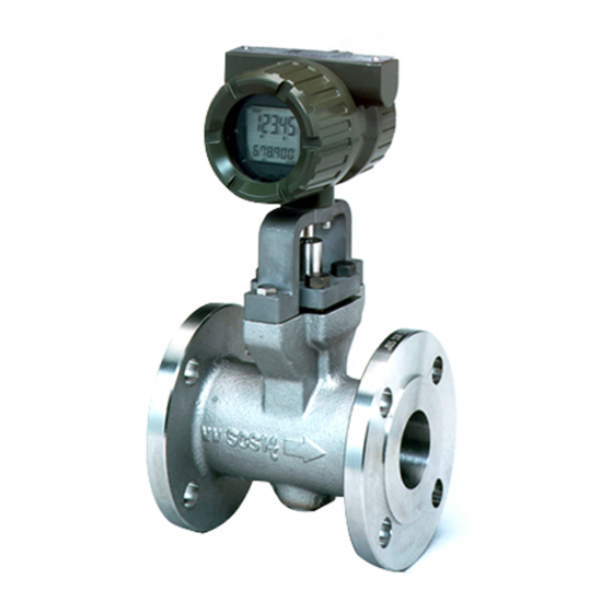
digitalYEWFLO Series
Vortex Flowmeter
F
Fieldbus
OUNDATION
Communication Type
IM 01F06F00-01EN
IM 01F06F00-01EN
10th Edition
Related Manuals for YOKOGAWA digitalYEWFLO Series
Summary of Contents for YOKOGAWA digitalYEWFLO Series
-
Page 1
User’s Manual digitalYEWFLO Series Vortex Flowmeter Fieldbus OUNDATION Communication Type IM 01F06F00-01EN IM 01F06F00-01EN 10th Edition… -
Page 2: Table Of Contents
Block Setting ………………… 5-6 5.6.1 Link Objects ………………5-6 5.6.2 Trend Objects ………………5-6 5.6.3 View Objects ………………5-7 5.6.4 Function Block Parameters…………..5-7 10th Edition: Aug. 2019 (KP) IM 01F06F00-01EN All Rights Reserved, Copyright © 2003, Yokogawa Electric Corporation…
-
Page 3
Toc-2 EXPLANATION OF BASIC ITEMS …………6-1 Setting and Changing Parameters for the Whole Process ……6-1 Transducer Block Parameters …………….. 6-2 AI Function Block Parameters …………….. 6-4 Parameters of DI Function Block …………..6-6 Integral LCD Indicator ………………6-6 IN-PROCESS OPERATION ………….. -
Page 4
Toc-3 APPENDIX 5. INTEGRATOR (IT) BLOCK …………A5-1 A5.1 Schematic Diagram of Integrator Block …………. A5-1 A5.2 Input Process Section ………………. A5-2 A5.2.1 Determining Input Value Statuses ………..A5-2 A5.2.2 Converting the Rate ……………..A5-2 A5.2.3 Converting Accumulation …………..A5-3 A5.2.4 Determining the Input Flow Direction……….A5-3 A5.3 Adder ………………….. -
Page 5
Toc-4 APPENDIX 7. LINK MASTER FUNCTIONS …………A7-1 A7.1 Link Active Scheduler………………A7-1 A7.2 Link Master ………………… A7-1 A7.3 Transfer of LAS ………………..A7-2 A7.4 LM Functions ………………..A7-3 A7.5 LM Parameters ………………..A7-4 A7.5.1 LM Parameter List …………….A7-4 A7.5.2 Descriptions for LM Parameters …………A7-6 A7.6 Trouble Shooting ………………. -
Page 6
Toc-5 APPENDIX 11. SOFTWARE DOWNLOAD (Option /EE) ……A11-1 A11.1 Benefits of Software Download …………..A11-1 A11.2 Specifications ………………..A11-1 A11.3 Preparations for Software Downloading …………A11-1 A11.4 Software Download Sequence …………..A11-2 A11.5 Download Files ………………..A11-2 A11.6 Steps after Activating a Field Device …………A11-3 A11.7 Troubleshooting ………………..A11-4 A11.8 Resource Block’s Parameters Relating to Software Download ….A11-4 A11.9… -
Page 7: Introduction
01F06A00-01EN. impaired. Regarding This Manual • Yokogawa will not be liable for malfunctions or damage resulting from any modification made • This manual should be provided to the end to this instrument by the customer.
-
Page 8: Using This Instrument Safety
If necessary, contact the instrument has been taken off the piping Yokogawa. line for maintenance and so forth. • Do not open the cover in wet weather or humid environment. When the cover is open, (5) Explosion Protected Type Instrument stated enclosure protection is not applicable.
-
Page 9: Warranty
Yokogawa. • Problems or damage resulting from repairs or modifications not performed by Yokogawa or someone authorized by Yokogawa. • Problems or damage resulting from inappropriate reinstallation after delivery.
-
Page 10: Atex Documentation
<1. INTRODUCTION> ATEX Documentation This is only applicable to the countries in European Union. IM 01F06F00-01EN…
-
Page 11: Amplifier For Fieldbus Communication
<2. AMPLIFIER FOR FIELDBUS COMMUNICATION> AMPLIFIER FOR FIELDBUS COMMUNICATION Read IM 01F06A00-01EN for the details of the amplifier. This section encompasses topics applicable to only the Fieldbus communication type. (1) The Fieldbus communication type has no local key access function. (2) The Fieldbus communication type has no BT200 (BRAIN TERMINAL) connection pin.
-
Page 12: About Fieldbus
Fieldbus F , and • Converts the flow sensor output to the OUNDATION provides interoperability between Yokogawa volumetric flow rate signal and transfers to an AI devices and those produced by other function block (AI1). manufacturers. Featuring two AI and two DI function •…
-
Page 13: Logical Structure Of Each Block
<3. ABOUT FIELDBUS> Logical Structure of Each Block digital System/network management VFD YEWFLO PD tag Communication parameters Node address Function block execution schedule Link master Function block VFD PID function block (option /LC1) IT function block function block DI2 function block DI1 function block…
-
Page 14: Getting Started
M4 screw terminals. Some hosts require a connector. Connection of Devices The following instruments are required for use with Read Yokogawa when making arrangements to Fieldbus devices: purchase the recommended equipment. Connect the devices as shown in Figure 4.1.
-
Page 15: Host Setting
Set 0x15 or Physical Location: greater. Note: V (NUN) Number-of- Unused address range. Our Device Description Files and Capabilities Files available at http://www.yokogawa.com/fld/ (English) consecutive- http://www.yokogawa.co.jp/fld/ (Japanese) Unpolled-Node DEVICE INFORMATION Device ID:5945430009XXXXXXXX PD XXXXXX Device Revision:X Node Address:0xXX Serial No.:XXXXXXXXXXXXXXXXX…
-
Page 16: Integration Of Dd
DD directory. Reading the Parameters 594543 : the manufacturer number of Yokogawa Electric Corporation To read digitalYEWFLO parameters, select the AI 0009 : the device number of digitalYEWFLO block of the digitalYEWFLO from the host screen If this directory is not found, the DD for the and read the OUT parameter.
-
Page 17: Generation Of Alarm
<4. GETTING STARTED> Generation of Alarm If the host is allowed to receive alarms, generation of an alarm can be attempted from the digitalYEWFLO. In this case, set the reception of alarms on the host side. The digitalYEWFLO’s VCR-7 is factory-set for this purpose. For practical purposes, all alarms are placed in a disabled status;…
-
Page 18: Configuration
<5. CONFIGURATION> CONFIGURATION This chapter describes how to adapt the function • Terminator and performance of the digitalYEWFLO to suit Fieldbus requires two terminators. Read the specific applications. Because multiple devices are supplier for details of terminators that are connected to Fieldbus, it is important to carefully attached to the host.
-
Page 19: Function Block Link Definitions
<5. CONFIGURATION> The node addresses are used to locate devices To ensure stable operation of Fieldbus, determine for communication purposes. Since a PD tag is too the operation parameters and set them to the LM long a data value, the host substitutes the node devices.
-
Page 20: Setting Of Tags And Addresses
<5. CONFIGURATION> Table 5.3 Function Block Execution Schedule of Macrocycle (Control Period) the digitalYEWFLO FI103 FI100 Setting (Factory Setting Index Parameters in Parentheses) CAS_IN FIC100 FC100 BKCAL_OUT 269 (SM) MACROCYCLE_ Repetition period of control BKCAL_IN DURATION or measurement, i.e., FC200 FIC200 FC100 macrocycle;…
-
Page 21: Communication Setting
<5. CONFIGURATION> Communication Setting In each digitalYEWFLO, the PD tag and node address are set to “FT1003” and 242 (hexadecimal To set the communication function, it is necessary F2), respectively, before shipment from the factory to change the database residing in SM (System unless otherwise specified.
-
Page 22: Function Block Execution Control
<5. CONFIGURATION> Table 5.4 VCR Static Entry Sub- Parameter Description index Sub- Parameter Description FmsVfdId Sets VFD for the index digitalYEWFLO to be used. FasArTypeAndRole Indicates the type and role of 0x1: System/network communication (VCR). The management VFD following 4 types are used for 0x1234: Function block the digitalYEWFLO.
-
Page 23: Block Setting
<5. CONFIGURATION> Block Setting 5.6.2 Trend Objects It is possible to make settings so that a function Set the parameter for function block VFD. block automatically transmits the trend. For this, 5.6.1 Link Objects each digitalYEWFLO has ten trend objects: eight for trends of analog parameters and two for discrete A link object combines the data voluntarily sent by the function block with the VCR.
-
Page 24: View Objects
<5. CONFIGURATION> System AI2 OUT Management Resource Transducer Information AI1 OUT block block Base (SMIB) Network Alert Management FBOD Information Trend Base (NMIB) Link object #3 #4 DLSAP 0xF8 0xF3 0xF4 0xF7 0xF9 0x20 0x07 DLCEP Fieldbus Cable Host 1 Host 2 Device F0505.ai…
-
Page 25
<5. CONFIGURATION> Table 5.11 View Objects for Resource Block Relative Parameter VIEW_ VIEW_ VIEW_ VIEW_ Relative Parameter VIEW_ VIEW_ VIEW_ VIEW_ Index Mnemonic Index Mnemonic ST_REV MAX_NOTIFY TAG_DESC LIM_NOTIFY STRATEGY CONFIRM_TIME ALERT_KEY WRITE_LOCK MODE_BLK UPDATE_EVT BLOCK_ERR BLOCK_ALM RS_STATE ALARM_SUM TEST_RW ACK_OPTION DD_RESOURCE WRITE_PRI… -
Page 26
<5. CONFIGURATION> Table 5.12 View Objects for Transducer Block Relative VIEW_3 VIEW_3 VIEW_3 VIEW_3 VIEW_4 VIEW_4 VIEW_4 VIEW_4 VIEW_4 VIEW_4 Parameter Mnemonic VIEW_1 VIEW_2 Index ST_REV TAG_DESC STRATEGY ALERT_KEY MODE_BLK BLOCK_ERR UPDATE_EVT BLOCK_ALM TRANSDUCER_ DIRECTORY TRANSDUCER_TYPE XD_ERROR COLLECTION_ DIRECTORY PRIMARY_VALUE_TYPE PRIMARY_VALUE PRIMARY_VALUE_ RANGE… -
Page 27
5-10 <5. CONFIGURATION> Relative VIEW_3 VIEW_3 VIEW_3 VIEW_3 VIEW_4 VIEW_4 VIEW_4 VIEW_4 VIEW_4 VIEW_4 Parameter Mnemonic VIEW_1 VIEW_2 Index TEMP_UNIT PROCESS_TEMP BASE_TEMP DENSITY_UNIT PROCESS_DENSITY BASE_DENSITY PRESSURE_UNIT PROCESS_PRESSURE BASE_PRESSURE DEVIATION SECONDARY_FTIME CABLE_LENGTH FIRST_TEMP_COEF SECOND_TEMP_COEF SIZE_SELECT BODY_TYPE VORTEX_SENSOR_ TYPE K_FACTOR_UNIT K_FACTOR LOWCUT UPPER_DISPLAY_MODE LOWER_DISPLAY_MODE DISPLAY_CYCLE… -
Page 28
5-11 <5. CONFIGURATION> Table 5.13 View Objects for Each AI Function Table 5.14 View Objects for Each DI Function Block Block Relative Parameter VIEW_ VIEW_ VIEW_ VIEW_ Relative Parameter VIEW_ VIEW_ VIEW_ VIEW_ Index Mnemonic Index Mnemonic ST_REV ST_REV TAG_DESC TAG_DESC STRATEGY STRATEGY… -
Page 29
5-12 <5. CONFIGURATION> Table 5.15 View Objects for PID Function Block (option /LC1) Relative Parameter VIEW_ VIEW_ VIEW_ VIEW_ Relative Parameter VIEW_ VIEW_ VIEW_ VIEW_ Index Mnemonic Index Mnemonic ST_REV FF_SCALE TAG_DESC FF_GAIN STRATEGY UPDATE_EVT ALERT_KEY BLOCK_ALM MODE_BLK ALARM_SUM BLOCK_ERR ACK_OPTION ALARM_HYS HI_HI_PRI… -
Page 30
5-13 <5. CONFIGURATION> Table 5.16 View Objects for Enhanced Arithmetic (AR) Block Relative Parameter VIEW_ VIEW_ VIEW_ VIEW_ Relative Parameter VIEW_ VIEW_ VIEW_ VIEW_ Index Mnemonic Index Mnemonic BAL_TIME ST_REV TAG_DESC BIAS STRATEGY GAIN ALERT_KEY OUT_HI_LIM MODE_BLK OUT_LO_LIM BLOCK_ERR UPDATE_EVT BLOCK_ALM AR_VOLUME_ FLOW_UNIT… -
Page 31
5-14 <5. CONFIGURATION> Table 5.17 View Objects for IT Function Block Table 5.18 Indexes to View Objects for Each Block Relative Parameter VIEW_ VIEW_ VIEW_ VIEW_ Block VIEW_1 VIEW_2 VIEW_3 VIEW_4 Index Mnemonic Resource block 40100 40101 40102 40103 ST_REV 40206 40202 40207… -
Page 32: Explanation Of Basic Items
<6. EXPLANATION OF BASIC ITEMS> EXPLANATION OF BASIC ITEMS 6.1 Setting and Changing This chapter describes basic TR (Transducer block), AI, and DI function block parameter setting, Parameters for the Whole displays of the integral indicator. For detailes of the Process function blocks, read APPENDIX.
-
Page 33: Transducer Block Parameters
<6. EXPLANATION OF BASIC ITEMS> 6.2 Transducer Block Parameters (1) Mandatory Parameter Setting for Transducer Block The transducer block sets functions specific to After setting parameters of the transducer block, the flow rate measurement of the digitalYEWFLO. set up XD_SCALE of the AI1 block (and of the For each block parameter in digitalYEWFLO, read AI2 block as appropriate).
-
Page 34
<6. EXPLANATION OF BASIC ITEMS> (2) Explanations of Parameters DENSITY_UNIT (Relative Index 53) Selects the unit of density. 1) PRIMARY_VALUE_TYPE (Relative Index 13) Setting range: 1097 (=kg/m Indicates the type of the measured item Default: 1097 (= kg/m represented by PRIMARY_VALUE. For the 9) PROCESS_DENSITY (Relative Index 54) digitalYEWFLO, the value of PRIMARY_ Selects the density under the normal…
 -
Page 35: Ai Function Block Parameters
<6. EXPLANATION OF BASIC ITEMS> 6.3 AI Function Block Parameters 17) K_FACTOR_UNIT (Relative Index 67) Selects the unit of the K factor. Parameters of the three AI function blocks can be Setting range: 1 (=p/L) read and written from the host. Default: 1 (=p/L).
-
Page 36
<6. EXPLANATION OF BASIC ITEMS> Table 6.2 Available Units Table 6.3 Setting Range of EU at 100 of XD_ SCALE Depending on Unit Item Block Available Units Block Unit Selected Setting Range of EU at 100 kg/s (1322), kg/min (1323), LIQUID: kg/h (1324), kg/d (1325), Read Table 6.2… -
Page 37: Parameters Of Di Function Block
<6. EXPLANATION OF BASIC ITEMS> 6.4 Parameters of DI Function Integral LCD Indicator Block The display items are as follows. Table 6.5 Display Items DI function blocks work based on the limit switch signals generated by the transducer block where Display Items Upper Display Mode DI1 is based on those signals on the flow rate and Flowrate%…
-
Page 38
<6. EXPLANATION OF BASIC ITEMS> Voluemetric Flow Rate at Normal Condition /s(1522), Nm /m(1523), Nm /h(1524), /d(1525), NL/s(1532), NL/m(1533), NL/h(1534), NL/d(1535), Sm /s(1527), /m(1528), Sm /h(1529), Sm /d(1530), SL/s(1537), SL/m(1538), SL/h(1539), SL/d(1540), SCFM(1360), SCFH(1361) N: Normal, S: Standard. Percentage %(1342) (1) Display Style In case of plus display Example : AR OUT_RANGE. -
Page 39: In-Process Operation
<7. IN-PROCESS OPERATION> IN-PROCESS OPERATION This chapter describes the procedure performed The error details corresponding to alarm indications when changing the operation of the function block on the LCD indicator and whether or not switches of the digitalYEWFLO in process. are provided to disable the corresponding alarms are shown in Table 7.1.
-
Page 40
<7. IN-PROCESS OPERATION> Table 7.1 Alarm Indications and Alarm Mask Switches Alarm Mask Alarm Mask Error Detail Error Detail SW (default) SW (default) AL-01 The EEPROM(S) failed. Not provided AR Range High (AR.RANGE_HI) is smaller Provided (OFF) AL-86 than AR Range Low (AR.RANGE_LOW). The serial communication circuit in the Not provided AL-02… -
Page 41: Alarms And Events
<7. IN-PROCESS OPERATION> Simulation Function 7.2.2 Alarms and Events Each digitalYEWFLO can report the following The simulation function simulates the input of a alarms and events as alerts. function block and lets it operate as if the data was Analog Alerts (Generated when a process value received from the transducer block.
-
Page 42: Device Status
<8. DEVICE STATUS> DEVICE STATUS In a digitalYEWFLO, the current device statuses and error details are represented by parameters DEVICE_STATUS_1 to DEVICE_STATUS_5 (indexes 1045 to 1049) inside the resource statuses. Table 8.1 Contents of DEVICE_STATUS_1 (Index 1045) Hexadecimal Display through DD Description 0x04000000 Abnormal boot process Abnormal boot processing was detected at the time of starting.
-
Page 43
<8. DEVICE STATUS> Table 8.3 Contents of DEVICE_STATUS_3 (Index 1047) Hexadecimal Display through DD Description 0x10000000 No FB scheduled (AL-20) No function blocks are scheduled. 0x02000000 TB in O/S mode (AL-22) The transducer block is in O/S mode. 0x01000000 AI1 in O/S mode (AL-23) The AI1 block is in O/S mode. -
Page 44
<8. DEVICE STATUS> Table 8.5 Contents of DEVICE_STATUS_5 (Index 1049) Hexadecimal Display through DD Description 0x08000000 AI3 in O/S mode (AL-28) AI3 Block is in O/S mode. 0x04000000 IT in O/S mode (AL-29) IT Block is in O/S mode. 0x02000000 AR in O/S mode (AL-30) AR Block is in O/S mode. -
Page 45: General Specifications
<9. GENERAL SPECIFICATIONS> GENERAL SPECIFICATIONS 9.1 Standard Specifications For items other than those described below, read GS 01F06A00-01EN. EMC Conformity Standards: EN 61326-1 Class A, Table 2 (For use in industrial locations), EN 61326-2-3, EN61326-2-5 • Performance Specification during immunity test Flowrate output: Output fluctuation within measurement accuracy Temperature output: Output fluctuation within ±1.0 °C Note1: This instrument is a Class A product, and it is designed for use in the industrial environment.
-
Page 46
<9. GENERAL SPECIFICATIONS> Mass Flow or Volumetric Flow at Norminal/Standard condition Accuracy using Arithmetic (AR) function block: (when Multi-Variable Type (option code: /MV), High Process Temperature Version Multi-Variable Type (combination of option code /HT and /MV) and outer pressure sensor are used) Accuracy ±… -
Page 47: Model And Suffix Codes
<9. GENERAL SPECIFICATIONS> Functional Specifications: Functional specifications for Fieldbus communication conform to the standard specifications (H1) of F OUNDATION fieldbus. Fieldbus specifications (ITK 5.0.1) grant the interoperability of the field instruments. OUNDATION Function blocks: Block name Number Execution time Note AI1: Monitors the fow rate and totalized flow rate; AI2: Monitors the temperature 29 ms for a model with the multi-variable type option;…
-
Page 48: Optional Specifications
<9. GENERAL SPECIFICATIONS> 9.3 Optional Specifications IMPORTANT In case of the remote type, select the same specification (code) for both detector and converter. For options other than below, read GS 01F06A00-01EN. (Note1) For intrinsically safe approval, use the barrier certified by the testing laboratories (BARD-400 is not applicable). (Note2) In case of /FF1, /KF2, /KS28, /KN26, /CF1, /CF11, /SF2 or /SS28 the screw length of Electrical Connection is deeper than ANSI standard for 0.5 to 2 threads.
-
Page 49
<9. GENERAL SPECIFICATIONS> Item Description Code ATEX ATEX Flameproof Approval Applicable Standard: EN 60079-0, EN 60079-1 Type of Protection: Ex db IIC T6…T1 Gb (Integral Type and Remote Type Detector) Ex db IIC T6 Gb (Remote Type Converter) Group : II, Category : 2 G Temperature Class : T6…T1 (Integral Type and Remote Type Detector) T6 (Remote Type Converter) Process Temperature : T6 (–40 to +80°C), T5 (–40 to +100°C), T4 (–40 to +135°C),… -
Page 50
<9. GENERAL SPECIFICATIONS> Item Description Code Canadian Standards CSA explosion-proof Approval Association (CSA) Applicable Standard: C22.1-98, C22.2 No.0, C22.2 No.0.4, C22.2 No.0.5, C22.2 No.25, C22.2 No.30, C22.2 No.94, C22.2 No.142, C22.2, No.61010-1, ANSI/ISA-12.27.01 Type of Protection: explosion-proof for Class I, Groups B, C and D; Class II, Groups E, F and G;… -
Page 51
<9. GENERAL SPECIFICATIONS> <Factory setting> AI2 for Temperature Signal Item AI1 for Flow Rate Signal (Standard) (with MV Option) Tag number (PD_TAG) Set to “FT1003” by default unless otherwise specified when ordered. Output mode (L_TYPE) “Direct” Upper and lower calculation range limits The upper range limit will be set to the and unit (XD_SCALE) maximum flow rate range specified in the… -
Page 52: Explosion Protected Type Instrument
10-1 <10. EXPLOSION PROTECTED TYPE INSTRUMENT> 10. EXPLOSION PROTECTED TYPE INSTRUMENT In this section, further requirements and differences Specification of Protection: for explosion protected type instrument are Temperature Class: (Integral Type and Remote described. For explosion protected type instrument, Type Detector) the description in this chapter is prior to other Temperature Class Process Temperature…
-
Page 53
10-2 <10. EXPLOSION PROTECTED TYPE INSTRUMENT> Group: II Ambient Temperature: -40 to +60°C (Integral Type) Category: 3 G Enclosure:IP66/67 -50 to +80[+78]°C (Remote Type Detector) -40 to +80°C (Remote Type Converter) Overvoltage Category:I Ambient Temperature: (Option /LT below -29°C, [ ] Option /MV at T6) Electrical Data: -40 to +60°C (Integral Type) -50 to +80 [+79]°C (Remote Type Detector) -
Page 54
Only personnel authorized by Yokogawa with appropriate torque. Care must be taken Electric Corporation can repair the equipment not to twist the conductor. -
Page 55
10-4 <10. EXPLOSION PROTECTED TYPE INSTRUMENT> (5) Installation Diagram of Intrinsically safe (and Note) [ Integral type ] [ Remote type ] F1002.ai Electrical data Ex ia II C Ex ic II C Rating1 (Entity) Rating2 (FISCO) Rating (Entity) Maximum Input Voltage Ui 24 Vdc 17.5 Vdc 32 Vdc… -
Page 56
10-5 <10. EXPLOSION PROTECTED TYPE INSTRUMENT> 10.2 FM (6) Screw Marking The type of electrical connection is stamped near (1) Technical Data the electrical connection port according to the following codes. • Explosion Proof Applicable Standard: Class 3600 2011, Screw size Marking Class 3611 2004, ISO M20 X 1.5 female Class 3615 2006,… -
Page 57
(2) Wiring The instrument modification or part replacements by other than authorized representative of • Explosion proof Yokogawa Electric Corporation is prohibited and will void the approval of FM Approvals. WARNING • All wiring shall comply with National Electrical Code ANSI/NFPA 70 and Local Electrical Code. -
Page 58
Intrinsically Safe Installation (Integral Type) Rev. Doc. No.: IFM021-A20 P.1 Rev. Doc. No.: IFM021-A20 P.2 Yokogawa Electric Corporation Yokogawa Electric Corporation Model: DY Series Date: April 18, 2014 Date: May 8, 2003 Notes: This drawing replaces the former control drawing IFM021-A12. -
Page 59
Division 2 Installation (Remote Type) Rev. Doc. No.: IFM021-A20 P.4 Rev. Doc. No.: IFM021-A20 P.5 Yokogawa Electric Corporation Yokogawa Electric Corporation Model: DY Series Date: April 18, 2014 Date: May 8, 2003 Notes: This drawing replaces the former control drawing IFM021-A12. -
Page 60: Iecex
10-9 <10. EXPLOSION PROTECTED TYPE INSTRUMENT> 10.3 IECEx • Intrinsically Safe Applicable Standard: IEC 60079-0:2011 IEC 60079-11:2011 Certificate: IECEx DEK 15.0012X WARNING Type of Protection: Ex ia IIC T4…T1 Ga (Integral Type) • Only trained persons use this instrument in Ex ia IIC T6…T1 Ga (Remote Type Detector) industrial locations.
-
Page 61
Confirm the power supply is cut off and the voltage of power supply terminal is not supplied. The grounding terminals are located on the inside Only personnel authorized by Yokogawa and outside of the terminal area. Electric Corporation can repair the equipment… -
Page 62: Csa
10-11 <10. EXPLOSION PROTECTED TYPE INSTRUMENT> 10.4 CSA (6) Name Plate (1) Technical Data Example for name plates in case of “Flameproof, Integral type” • Explosion Proof Applicable Standard: C22.1-98, C22.2 No.0-M1991, C22.2 No.0.4-04, C22.2 No.0.5-1982, C22.2 No. 25- 1966, C22.2 No. 30-M1986, C22.2 No.
-
Page 63
(4) Maintenance and Repair WARNING The instrument modification or part replacements by other than authorized representatives of Yokogawa Electric Corporation are prohibited and will void CSA Certification. (5) Dual Seal (Option /CF11) Dual Seal: Certified by CSA to the requirement of ANSI/ISA 12.27.01… -
Page 64: Tiis
10-13 <10. EXPLOSION PROTECTED TYPE INSTRUMENT> 10.5 TIIS Certificate: Integral Type Flowmeter Remote Type Detector Shedder Model bar Material N (None Indicator) D (With Indicator) N (None Indicator) DY015 TC14901 TC14912 TC14923 DY025/R1 TC18903 TC18914 TC18925 DY040/R2 DY025 TC19504 TC19513 TC19522 DY040/R1 TC18904…
-
Page 65: Appendix 1. List Of Parameters
A1-1 <APPENDIX 1. LIST OF PARAMETERS FOR EACH BLOCK OF digitalYEWFLO> APPENDIX 1. LIST OF PARAMETERS FOR EACH BLOCK OF digitalYEWFLO Note: The Write Mode column contains the modes in which each parameter is write enabled. O/S: Write enabled in O/S mode. MAN: Write enabled in Man mode and O/S mode.
-
Page 66
A1-2 <APPENDIX 1. LIST OF PARAMETERS FOR EACH BLOCK OF digitalYEWFLO> Relative Write Index Parameter Name Factory Default Explanation Index Mode 1018 FEATURE_SEL 0x000a AUTO Used to select resource block options. (Soft write lock Bit0: Scheduled supported Bit1: Event driven Report supported) Bit2: Manufacturer specified 1019… -
Page 67: A1.2 Al Function Block
<APPENDIX 1. LIST OF PARAMETERS FOR EACH BLOCK OF digitalYEWFLO> Relative Write Index Parameter Name Factory Default Explanation Index Mode 1043 SOFT_DESC — Yokogawa internal use. 1044 SIM_ENABLE_MSG (Spaces) AUTO Software switch for simulation function. 1045 DEVICE_STATUS_1 — — Device status (VCR setting etc.) 1046 DEVICE_STATUS_2 —…
-
Page 68
A1-4 <APPENDIX 1. LIST OF PARAMETERS FOR EACH BLOCK OF digitalYEWFLO> Index Relative Factory Parameter Name Write Mode Explanation Index Default 4010 4110 4210 XD_SCALE Specified at the The high and low scale values, engineering units code, time of order and number of digits to the right of the decimal point (Note 3) (-40 to used with the value obtained from the transducer for a… -
Page 69
A1-5 <APPENDIX 1. LIST OF PARAMETERS FOR EACH BLOCK OF digitalYEWFLO> Index Relative Factory Parameter Name Write Mode Explanation Index Default 4028 4128 4228 HI_LIM 1. #INF AUTO The setting for high alarm in engineering units. (Note 1) 4029 4129 4229 LO_PRI AUTO Priority of the low alarm. -
Page 70: A1.3 Transducer Block
A1-6 <APPENDIX 1. LIST OF PARAMETERS FOR EACH BLOCK OF digitalYEWFLO> A1.3 Transducer Block Relative Write Index Parameter Name Factory Default Explanation Index Mode 2000 Block Header TAG: «TB» Block Tag Information on this block such as Block Tag, DD Revision, = O/S Execution Time etc.
-
Page 71
A1-7 <APPENDIX 1. LIST OF PARAMETERS FOR EACH BLOCK OF digitalYEWFLO> Relative Write Index Parameter Name Factory Default Explanation Index Mode 2026 SENSOR_CAL — Sets/indicates the name of the person responsible for the _WHO last sensor calibration. 2027 LIN_TYPE linear with input (1) —… -
Page 72
A1-8 <APPENDIX 1. LIST OF PARAMETERS FOR EACH BLOCK OF digitalYEWFLO> Relative Write Index Parameter Name Factory Default Explanation Index Mode 2043 LIMSW_2 _ Sets the hysteresis of limit switch 2 to be applied HYSTERESIS for resetting the LIMSW_2_VALUE_D to OFF after LIMSW_2_TARGET went beyond LIMSW_2_SETPOINT and LIMSW_2_VALUE_D turned ON (when used as a high-limit switch), or after LIMSW_2_TARGET went below… -
Page 73
A1-9 <APPENDIX 1. LIST OF PARAMETERS FOR EACH BLOCK OF digitalYEWFLO> Relative Write Index Parameter Name Factory Default Explanation Index Mode 2063 SECOND_TEMP Sets the second temperature coefficient for the density _COEF compensation of a liquid. Setting range: –32000 to 32000 Unit: 1/TEMP_UNIT^2 2064 SIZE_SELECT… -
Page 74
A1-10 <APPENDIX 1. LIST OF PARAMETERS FOR EACH BLOCK OF digitalYEWFLO> Relative Write Index Parameter Name Factory Default Explanation Index Mode 2082 NOISE_RATIO — — Indicates the noise balance ratio. When the value of NOISE_BALANCE_MODE is 1 (Auto), this value cannot be modified. -
Page 75
A1-11 <APPENDIX 1. LIST OF PARAMETERS FOR EACH BLOCK OF digitalYEWFLO> A1.4 DI Function Block Index Relative Write Parameter Name Factory Default Explanation Index Mode 6000 6100 Block Header TAG: «DI1» or «DI2» Block Tag Information on this block such as the block tag, DD revision, = O/S and execution time 6001… -
Page 76: Appendix 2. Application, Setting And Change Of Basic Parameters
A2-1 <APPENDIX 2. APPLICATION, SETTING AND CHANGE OF BASIC PARAMETERS> APPENDIX 2. APPLICATION, SETTING AND CHANGE OF BASIC PARAMETERS A2.1 Applications and Selection of Basic Parameters Setting Item (applicable parameters) Summary Tag numbers (PD-TAG) Set the physical device (PD) tag and block tags. Up to 32 alphanumeric characters can be set for each of these tags.
-
Page 77: A2.2 Setting And Change Of
A2-2 <APPENDIX 2. APPLICATION, SETTING AND CHANGE OF BASIC PARAMETERS> A2.2 Setting and Change of Transducer Resource Function Function Block Block Basic Parameters Block Block Automatic This section describes the procedure taken to (Auto) set and change the parameters for each block. Manual (Man) Obtaining access to each parameter differs…
-
Page 78
A2-3 <APPENDIX 2. APPLICATION, SETTING AND CHANGE OF BASIC PARAMETERS> (1)-2. Setting the output scale Example: To set the output range to 0 to 100%, Access the OUT_SCALE parameter. Set EU at 100% of XD_SCALE to 100. Set the required unit in Unit Index of Set EU at 0% of XD_SCALE to 0. -
Page 79: A2.4 Setting The Transducer Block
A2-4 <APPENDIX 2. APPLICATION, SETTING AND CHANGE OF BASIC PARAMETERS> A2.4 Setting the Transducer Block The above shows the setting procedure for limit switch 1. As necessary, also set up limit switch 2. To access the digitalYEWFLO-specific functions in the transducer block, the Device Description (DD) (4) Setting up the LCD display for the digitalYEWFLO needs to have been installed Select the data to be displayed on the LCD indicator…
-
Page 80
A2-5 <APPENDIX 2. APPLICATION, SETTING AND CHANGE OF BASIC PARAMETERS> The UPPER_DISPLAY_MODE and LOWER_ DISPLAY_MODE parameter settings in the transducer (TR) block, and the L_TYPE settings in the AI1 and AI2 blocks determine which data items, and their values and units, are displayed on the LCD indicator, as shown in the following tables. -
Page 81: A2.5 Setting The Di Function Blocks
A2-6 <APPENDIX 2. APPLICATION, SETTING AND CHANGE OF BASIC PARAMETERS> A2.5 Setting the DI Function Blocks DI function blocks output limit switch signals received from the transducer block. Two DI blocks (DI1 and DI2) in each digitalYEWFLO have independent parameters. Set up the parameters of each AI block you use, individually as necessary.
-
Page 82: Appendix 3. Operation Of Each Parameter In Failure Mode
A3-1 <APPENDIX 3. OPERATION OF EACH PARAMETER IN FAILURE MODE> APPENDIX 3. OPERATION OF EACH PARAMETER IN FAILURE MODE *1: Standard Type and Multi-variable Type with THERMOMETER_FUNCTION in TR block Set to “Monitor Only” or “Not Use” *2: Multi-variable Type with THERMOMETER_FUNCTION Used for Density Calculation Alarm Reset Alarm Detail RS Block…
-
Page 83
A3-2 <APPENDIX 3. OPERATION OF EACH PARAMETER IN FAILURE MODE> Alarm Reset Alarm Detail RS Block TR Block AI1 Block AI2 Block AI3 Block Display SW* (default) <PV.Status> <BLOCK_ERR> Uncertain-Non <PV.Status> Other Specific • Default Bad-Non Specific <PV.Status> • Default •… -
Page 84
A3-3 <APPENDIX 3. OPERATION OF EACH PARAMETER IN FAILURE MODE> Alarm Reset SW* Alarm Detail DI1 Block DI2 Block PID Block IT Block AR Block Display (default) <PV_D.Status> • Default Bad-Non Specific • STATUS_OPTS: Propagate Fault Forward=Active Bad-Device Failure AMP. Module AL-01 Not provided Failure 1 (AL-01) -
Page 85
A3-4 <APPENDIX 3. OPERATION OF EACH PARAMETER IN FAILURE MODE> Alarm Reset SW* Alarm Detail DI1 Block DI2 Block PID Block IT Block AR Block Display (default) <PV_D.Status> • TARGET in TB’s LIMSW = PRIMARY_VALUE Uncertain-Non Specific • TARGET in TB’s LIMSW = SECONDARY_ VALUE •… -
Page 86
A3-5 <APPENDIX 3. OPERATION OF EACH PARAMETER IN FAILURE MODE> Alarm Reset SW* Alarm Detail RS Block TR Block AI1 Block AI2 Block AI3 Block Display (default) <BLOCK_ERR> <PV.Status> <PV.Status> Other • Default • Default Bad-Non Specific Bad-Non Specific • STATUS_OPTS: •… -
Page 87
A3-6 <APPENDIX 3. OPERATION OF EACH PARAMETER IN FAILURE MODE> AlarmReset Alarm Detail DI1 Block DI2 Block PID Block IT Block AR Block Display SW* (default) <PV_D.Status> • TARGET in TB’s LIMSW = SECONDARY_VALUE • Default Bad-Non Specific • STATUS_OPTS:Propagate Fault Forward = Active Bad-Device Failure •… -
Page 88
A3-7 <APPENDIX 3. OPERATION OF EACH PARAMETER IN FAILURE MODE> AlarmReset Alarm Detail DI1 Block DI2 Block PID Block IT Block AR Block Display SW* (default) AI1 in O/S Provided AL-23 Mode (ON) (AL-23) AI2 in O/S Provided AL-24 Mode (OFF) (AL-24) <BLOCK_ERR>… -
Page 89
A3-8 <APPENDIX 3. OPERATION OF EACH PARAMETER IN FAILURE MODE> Alarm Reset SW* Alarm Detail RS Block TR Block AI1 Block AI2 Block AI3 Block Display (default) PID in O/S Provided AL-27 Mode (AL-27) (OFF) <BLOCK_ERR> Out of Service AI3 in O/S Provided AL-28 Mode (AL-28) -
Page 90
A3-9 <APPENDIX 3. OPERATION OF EACH PARAMETER IN FAILURE MODE> Alarm Reset SW* Alarm Detail DI1 Block DI2 Block PID Block IT Block AR Block Display (default) <BLOCK_ERR> Out of Service PID in O/S Provided AL-27 Mode (AL-27) (OFF) <OUT.Status> Bad-Out of Service AI3 in O/S Provided… -
Page 91
A3-10 <APPENDIX 3. OPERATION OF EACH PARAMETER IN FAILURE MODE> Alarm Reset SW* Alarm Detail DI1 Block DI2 Block PID Block IT Block AR Block Display (default) <PV_D.Status> • TARGET in TB’s LIMSW = SECONDARY_VALUE Uncertain-Non Specific Clogging (AL- Provided AL-53 (OFF) <OUT_D.Status>… -
Page 92
A3-11 <APPENDIX 3. OPERATION OF EACH PARAMETER IN FAILURE MODE> Alarm Reset SW* Alarm Detail RS Block TR Block AI1 Block AI2 Block AI3 Block Display (default) <OUT.Status> • Default • STATUS_OPTS: AI1 in Man Provided AL-62 Uncertain if Man Mode (AL-62) (ON) mode = Active… -
Page 93
A3-12 <APPENDIX 3. OPERATION OF EACH PARAMETER IN FAILURE MODE> Alarm Reset SW* Alarm Detail DI1 Block DI2 Block PID Block IT Block AR Block Display (default) AI1 in Man Provided AL-62 Mode (AL-62) (ON) AI1 Simulation Provided AL-63 Active (AL-63) (ON) AI1 Not Provided… -
Page 94
A3-13 <APPENDIX 3. OPERATION OF EACH PARAMETER IN FAILURE MODE> Alarm Reset SW* Alarm Detail RS Block TR Block AI1 Block AI2 Block AI3 Block Display (default) <OUT.Status> • Default • STATUS_OPTS: AI3 in Man Provided AL-77 Uncertain if Man Mode (AL-77) (OFF) mode = Active… -
Page 95
A3-14 <APPENDIX 3. OPERATION OF EACH PARAMETER IN FAILURE MODE> Alarm Reset SW* Alarm Detail DI1 Block DI2 Block PID Block IT Block AR Block Display (default) AI3 in Man Provided AL-77 Mode (AL-77) (OFF) AI3 Simulation Provided AL-78 Active (AL-78) (OFF) AI3 Not Provided… -
Page 96
A3-15 <APPENDIX 3. OPERATION OF EACH PARAMETER IN FAILURE MODE> Alarm Reset Switch Settings Some alarms can be disabled and enabled using switches in parameter ALARM_PERFORM inside the transducer block as explained below. (1) Setting As shown in the following table, the individual bits of ALARM_PERFORM at relative index 45 act as switches to disable and enable particular alarms. -
Page 97: Appendix 4. Function Diagrams Of Function Blocks
A4-1 <APPENDIX 4. FUNCTION DIAGRAMS OF FUNCTION BLOCKS> APPENDIX 4. FUNCTION DIAGRAMS OF FUNCTION BLOCKS A4.1 AI Function Block Transducer FA0401.ai Figure A4.1 Input/Output of AI Block FIELD_VAL.Value L_TYPE Ind.Sqr Root /100 Simulate Scaling Scaling Filter Cutoff CHANNEL SIMULATE XD_SCALE OUT_SCALE PV_FTIME LOW_CUT…
-
Page 98: Appendix 5. Integrator (It) Block
A5-1 <APPENDIX 5. INTEGRATOR (IT) BLOCK> APPENDIX 5. INTEGRATOR (IT) BLOCK The Integrator (IT) block adds two main inputs and OUT.Value = Integration start value + Total integrates them for output. The block compares the Total = Total + Current Integral integrated or accumulated value to TOTAL_SP and Current Integral = (x + y) ×…
-
Page 99: A5.2 Input Process Section
A5-2 <APPENDIX 5. INTEGRATOR (IT) BLOCK> A5.2 Input Process Section When executed, the Integrator block first performs input processing in the order of: “Determining input status” → “Converting Rate or Accum” → “Determining the input flow direction” Switching between Convert Rate and Convert Accum is made using bit 0 (for IN_1) or bit 1 (for IN_2) of INTEG_OPTS.
-
Page 100: A5.2.3 Converting Accumulation
A5-3 <APPENDIX 5. INTEGRATOR (IT) BLOCK> A5.2.3 Converting Accumulation A5.2.4 Determining the Input Flow Direction This following describes an example of accumulation conversion. The Integrator block also considers the input flow In accumulation conversion, the difference between direction. Information about the input flow direction the value executed previously and the value is contained in REV_FLOW1 and REV_FLOW2 (0: executed this time is integrated or accumulated.
-
Page 101: A5.3 Adder
A5-4 <APPENDIX 5. INTEGRATOR (IT) BLOCK> A5.3 Adder A5.4 Integrator When input processing is complete, two arguments When addition is complete, its result will be passed that have been rate and accumulate converted will to the integrator. be passed to the adder. The adder adds these two Integration consists of combinations of a reset values according to the option.
-
Page 102
A5-5 <APPENDIX 5. INTEGRATOR (IT) BLOCK> Table A5.1 INTEG_TYPE Integration Reset Trigger (Reset if one of the Name Integration Range Trip Output Method following conditions is established) -INF< Total <TOTAL_SP • OUT reaches TOTAL_SP Counting up 0< ATotal <+INF ○ UP_AUTO(1) •… -
Page 103: A5.5 Output Process
A5-6 <APPENDIX 5. INTEGRATOR (IT) BLOCK> A5.5 Output Process A5.5.1 Status Determination The same criteria for determining the status of the There are the following three output parameters: output of the Integrator block are used in common 1. OUT for the above three parameters. 2.
-
Page 104: A5.5.2 Determining The Output Value
A5-7 <APPENDIX 5. INTEGRATOR (IT) BLOCK> A5.5.2 Determining the Output Value If OUT is rewritten in the MAN mode, integration starts with the value rewritten in MAN mode after The value of OUT.Value is determined as follows: the mode was returned to AUTO. ●…
-
Page 105: A5.5.3 Mode Handling
A5-8 <APPENDIX 5. INTEGRATOR (IT) BLOCK> A5.5.3 Mode Handling Mode Action Output Automatic (AUTO) Normal action Normal output Integration calculation is stopped. You may rewrite a value in OUT. If no value is rewritten, the value just before Manual (MAN) OUT will not be updated unless you running in AUTO is held.
-
Page 106: A5.6.3 Reset Process
A5-9 <APPENDIX 5. INTEGRATOR (IT) BLOCK> A5.6.3 Reset Process The basic reset process sequence is as follows: 1. Snapshot 2. Clearing the integrated values 3. Reset count increment 4. Judging OUT_TRIP and OUT_PTRIP 1. Snapshot Saves the following values in the specified parameters before clearing the integrated values.
-
Page 107: A5.7 List Of Integrator Block Parameters
A5-10 <APPENDIX 5. INTEGRATOR (IT) BLOCK> A5.7 List of Integrator Block Parameters Write Index Parameter Name Initial Value Definition Mode Block Tag Information relating to this function block, such as block tag, BLOCK_HEADER TAG: “IT” =O/S DD revision, execution time ST_REV —…
-
Page 108
A5-11 <APPENDIX 5. INTEGRATOR (IT) BLOCK> Write Index Parameter Name Initial Value Definition Mode Specifies an integration optional function. Option Name Description Input 1 accumulate Selects Rate or Accum input of IN_1. Input 2 accumulate Selects Rate or Accum input of IN_2. Flow forward Integrates forward flow (interprets reverse flow as zero).* Flow reverse… -
Page 109: Appendix 6. Enhanced Arithmetic (Ar) Block
A6-1 <APPENDIX 6. Enhanced ARITHMETIC (AR) BLOCK> APPENDIX 6. Enhanced ARITHMETIC (AR) BLOCK The Arithmetic (AR) block switches two main inputs of different measurement ranges seamlessly and combines the result with three auxiliary inputs through the selected compensation function (10 types) to calculate the output.
-
Page 110: A6.2 Input Section
A6-2 <APPENDIX 6. Enhanced ARITHMETIC (AR) BLOCK> A6.2 Input Section PV is a parameter with status information, and PV status is determined by the value of “g.” There are five inputs: IN and IN_LO main inputs If “g” < 0.5 → The status of IN_LO is used. and IN_1, IN_2, and IN_3 auxiliary inputs.
-
Page 111: A6.2.3 Input_Opts
A6-3 <APPENDIX 6. Enhanced ARITHMETIC (AR) BLOCK> A6.2.3 INPUT_OPTS • If the status of IN is anything other than “good” and that of “IN_LO” is “good” INPUT_OPTS has an option that handles an input IN_LO < RANGE_HI → PV = IN_LO with “uncertain”…
-
Page 112: A6.3 Computation Section
A6-4 <APPENDIX 6. Enhanced ARITHMETIC (AR) BLOCK> A6.3 Computation Section 33) Saturated steam (Pressure): Saturated steam density calculation (by pressure based on IAPWS-IF97) A6.3.1 Computing Equations func = PV x Correction Value. This subsection shows computing equations used Correction Value: Saturated steam density in the computation section: calculated from t_2 (Press.
-
Page 113: A6.3.3 Compensated Values
A6-5 <APPENDIX 6. Enhanced ARITHMETIC (AR) BLOCK> A6.4 Output Section A6.3.3 Compensated Values In computing equations 1) to 5) in APPENDIX After executing the computing equation, the block 6.3.1 “Computing Equations” and 32) to 38) applies a gain to the calculated result and then adds in APPENDIX 6.3.2 “Enhanced Computing a bias to it.
-
Page 114: A6.4.1 Mode Handling
A6-6 <APPENDIX 6. Enhanced ARITHMETIC (AR) BLOCK> A6.4.1 Mode Handling A6.4.2 Status Handling The setting of INPUT_OPTS is applied to the input Mode Output status. When INPUT_OPTS is applied, there are Auto OUT = PRE_OUT cases where the PV status becomes “good” even if For OUT, the OUT value in the Auto mode just before change to MAN or O/S is retained.
-
Page 115: A6.5 List Of The Arithmetic Block Parameters
A6-7 <APPENDIX 6. Enhanced ARITHMETIC (AR) BLOCK> A6.5 List of the Arithmetic Block Parameters Relative Initial Parameter Write Mode Description / Remarks Index Value Information relating to this function block, such as block tag, DD revision, and Block Header Block Tag = O/S TAG=“AR” execution time Indicates the revision level of the set parameters associated with the Arithmetic ST_REV…
-
Page 116
A6-8 <APPENDIX 6. Enhanced ARITHMETIC (AR) BLOCK> Relative Initial Parameter Write Mode Description / Remarks Index Value Computation algorithm identification no. Value Selection Name Description Flow compensation, linear Flow compensation (linear) Flow compensation, square root Flow compensation (square root) Flow compensation, approximate Flow compensation (approximate expression) BTU flow (*) Quantity of heat calculation Traditional Multiply Divide… -
Page 117: A6.6 Example Of Connection
A6-9 <APPENDIX 6. Enhanced ARITHMETIC (AR) BLOCK> Relative Initial Parameter Write Mode Description / Remarks Index Value AR_CONFIG_ Memo; The version of MV tool which is calculated multinominal approximation AUTO (Space) SOFT_REV coefficient. AR_CONFIG_ Memo; The date of multinomial approximation coefficient setting. AUTO (Space) DATE…
-
Page 118: A6.7 Setting Procedure Of The Mass Flow Rate Calculation
A6-10 <APPENDIX 6. Enhanced ARITHMETIC (AR) BLOCK> A6.7 Setting Procedure of the Mass Flow Rate Calculation Mass flow rate calculation, Setting start Choose from the following ARITH_TYPE. Choice of calculation method 32 : Saturated steam (Temperature) (Saturated steam density calculation (Temperature)) 33 : Saturated steam (Pressure) (Saturated steam density calculation (Temperature)) 34 : Superheat steam (Superheat steam density calculation) 35 : Gas temperature pressure compensation (Gas temperature and pressure correction operation)
-
Page 119: Appendix 7. Link Master Functions
A7-1 <APPENDIX 7. LINK MASTER FUNCTIONS> APPENDIX 7. LINK MASTER FUNCTIONS A7.1 Link Active Scheduler A link active scheduler (LAS) is a deterministic, centralized bus scheduler that can control communications on an H1 fieldbus segment. There is only one LAS on an H1 fieldbus segment. A digitalYEWFLO supports the following LAS functions.
-
Page 120: A7.3 Transfer Of Las
A7-2 <APPENDIX 7. LINK MASTER FUNCTIONS> A7.3 Transfer of LAS There are two procedures for an LM to become the LAS: (1) If the LM whose value of [V(ST)×V(TN)] is the smallest on a segment, with the exception of the current LAS, judges that there is no LAS on the segment, in such a case as when the segment has started up or when the current LAS has failed, the LM declares itself as the LAS, then becomes the LAS.
-
Page 121: A7.4 Lm Functions
A7-3 <APPENDIX 7. LINK MASTER FUNCTIONS> (3) In the LAS settings of the digitalYEWFLO, set the values of V(FUN) and V(NUN) so that they include the node addresses of all nodes within the same segment. (Read Figure A7.3.) ConfiguredLinkSettingsRecord (digitalYEWFLO Index 369 (SM)) Default Subindex Element…
-
Page 122: A7.5 Lm Parameters
A7-4 <APPENDIX 7. LINK MASTER FUNCTIONS> A7.5 LM Parameters A7.5.1 LM Parameter List The tables below show LM parameters of a digitalYEWFLO. Meanings of Access column entries: RW = read/write possible; R = read only Index Sub-parameter Name Default Factory Parameter Name Access Remarks…
-
Page 123
A7-5 <APPENDIX 7. LINK MASTER FUNCTIONS> Index Sub-parameter Name Default Factory Parameter Name Access Remarks (SM) (Sub Index) Setting 370 PLME_BASIC_ CHARACTERISTICS 1 ChannelStatisticsSupported 0x00 2 MediumAndDataRatesSupported 0x4900000000000000 3 IecVersion 1 (0x1) 4 NumOfChannels 1 (0x1) 5 PowerMode 0 (0x0) 371 CHANNEL_STATES 1 channel-1 0 (0x0) -
Page 124: A7.5.2 Descriptions For Lm Parameters
A7-6 <APPENDIX 7. LINK MASTER FUNCTIONS> A7.5.2 Descriptions for LM Parameters 0x00 00 84 00 00 00 00 00 00 00 00 00 00 00 00 00 00 00 00 00 00 00 00 00 The following describes LM parameters of 00 00 00 00 00 00 00 00 digitalYEWFLO.
-
Page 125
Indicates the maximum number NumOf SchedulesPer of sub-schedules an LAS Channels Schedule schedule can contain. (This Power 0: Bus-powered; is fixed to 1 in the Yokogawa Mode 1: Self-powered communication stacks.) ActiveSchedule Indicates the version number Version of the schedule currently executed. -
Page 126: A7.6 Trouble Shooting
A7-8 <APPENDIX 7. LINK MASTER FUNCTIONS> (14) DlmeScheduleDescriptor A2-2. Make the digitalYEWFLO declare itself as and become the LAS by writing: This parameter exists for the same number as the • 0x00 (false) to total number of domains, and each describes the PrimaryLinkMasterFlagVariable in the LAS schedule downloaded to the corresponding current LAS;…
-
Page 127
A7-9 <APPENDIX 7. LINK MASTER FUNCTIONS> A4-2. Make the parameters in the current LAS match the capabilities parameter in the digitalYEWFLO as follows (Read Section 5.2 “Network Definition”): digitalYEWFLO V(ST) > V(ST) ≥ 4 V(MID) > V(MID) ≥ 4 V(MRD) >… -
Page 128: Appendix 8. Pid Block
A8-1 <APPENDIX 8. PID BLOCK> APPENDIX 8. PID BLOCK A PID block performs the PID control computation based on the deviation of the measured value (PV) from the setpoint (SV), and is generally used for constant-setpoint and cascaded-setpoint control. A8.1 Function Diagram The figure below depicts the function diagram of a PID block.
-
Page 129: A8.3 Parameters Of Pid Block
A8-2 <APPENDIX 8. PID BLOCK> A8.3 Parameters of PID Block NOTE: In the table below, the Write column shows the modes in which the respective parameters can be written. A blank in the Write column indicates that the corresponding parameter can be written in all modes of the PID block.
-
Page 130
A8-3 <APPENDIX 8. PID BLOCK> Default Index Parameter Name Write Valid Range Description (factory setting) 36 ROUT_OUT – Remote control output value 37 TRK_SCALE Upper and lower scale limits used to convert the output tracking value (TRK_VAL) to non-dimensional. 1342 (%) 38 TRK_IN_D Switch for output tracking. -
Page 131: A8.4 Pid Computation Details
A8-4 <APPENDIX 8. PID BLOCK> A8.4 PID Computation Details The subscripts, n and n-1, represent the time of sampling such that PVn and PVn-1 denote For PID control, the PID block in a digitalYEWFLO the PV value sampled most recently and the PV employs the PV-proportional and -derivative type value sampled at the preceding control period, PID control algorithm (referred to as the I-PD…
-
Page 132: A8.7 Control Action Bypass
A8-5 <APPENDIX 8. PID BLOCK> A8.7 Control Action Bypass A8.9 Block Modes The PID control computation can be bypassed so The block mode is set in the parameter MODE_ as to set the SP value in the control output OUT as BLK.
-
Page 133: A8.10 Bumpless Transfer
A8-6 <APPENDIX 8. PID BLOCK> A8.10 Bumpless Transfer Mode Transitions Transition Prevents a sudden change in the control output Destination Condition OUT at changes in block mode (MODE_BLK) and Conditions Mode at switching of the connection from the control 1 O/S If O/S is set in MODE_ BLK.
-
Page 134: A8.12 External-Output Tracking
A8-7 <APPENDIX 8. PID BLOCK> A8.12 External-output Tracking • CONTROL_OPTS Options in External tracking is an action of outputting the value Description CONTROL_OPTS of the remote output TRK_VAL set from outside Bypass Enable This parameter allows BYPASS to be set. the PID block, as illustrated in the figure below.
-
Page 135: A8.15 Manual Fallback
A8-8 <APPENDIX 8. PID BLOCK> A8.15 Manual Fallback A8.16 Auto Fallback Manual fallback denotes an action in which a Auto fallback denotes an action in which a PID PID block changes mode to MAN (manual) and block changes mode from CAS (cascade) to AUTO suspends the control action.
-
Page 136: A8.18 Alarms
A8-9 <APPENDIX 8. PID BLOCK> A8.18 Alarms Available Setting Actions upon Computer Failure for SHED_OPT There are two kinds of alarms generated by a PID Normal shed, Sets MODE_BLK.actual to Cas*, and leaves MODE_BLK.target unchanged. normal return block: block and process alarms. Normal shed, no Sets both MODE_BLK.actual and MODE_ A8.18.1 Block Alarm (BLOCK_ALM)
-
Page 137: A8.19 Example Of Block Connections
A8-10 <APPENDIX 8. PID BLOCK> A8.19 Example of Block Connections BKCAL_IN CAS_IN BKCAL_OUT FA0808.ai When configuring a simple PID control loop by combining a digitalYEWFLO with a fieldbus valve positioner that contains an AO block, follow the procedure below to make the settings of the corresponding fieldbus function blocks: 1.
-
Page 138: Appendix 9. Dd Menu
A9-1 <APPENDIX 9. DD MENU> APPENDIX 9. DD MENU (1) Resource Block Menus Alert Parameters Block Info Block Tag Block Alarm Unacknowledged Tag Description Strategy Alarm State Time Stamp Alert Key Block Mode Subcode Value Target Actual Alarm Sum Current Permitted Normal Unacknowledged…
-
Page 139
A9-2 <APPENDIX 9. DD MENU> (2) Transducer Block Transducer Block (Top menu) Characterize Meter Block Info Size Select Block Tag Body Type Tag Description Vortex Sensor Type Strategy K-Factor Unit Alert Key K-Factor Value Transducer Directory Display Set Transducer Type Upper Display Mode Block Mode Lower Display Mode… -
Page 140
A9-3 <APPENDIX 9. DD MENU> (3) AI1 Function Block Menus Diagnostics/Alerts Block Info Block Error Block Tag Alert Parameters Tag Description Block Almarm Strategy Unacknowledged Alert Key Alarm State Block Mode Time Stamp Target Subcode Actual Value Permitted Alarm Summary Normal Current Dynamic Variables… -
Page 141
A9-4 <APPENDIX 9. DD MENU> (4) AI2 Function Block Menus Block Info Diagnostics/Alerts Block Tag Block Error Tag Description Alert Parameters Strategy Block Almarm Alert Key Unacknowledged Block Mode Alarm State Target Time Stamp Actual Subcode Permitted Value Normal Alarm Summary Dynamic Variables Current Field Value… -
Page 142
A9-5 <APPENDIX 9. DD MENU> (5) AI3 Function Block Menus Block Info Diagnostics/Alerts Block Tag Block Error Tag Description Alert Parameters Strategy Block Almarm Alert Key Unacknowledged Block Mode Alarm State Target Time Stamp Actual Subcode Permitted Value Normal Alarm Summary Dynamic Variables Current Field Value… -
Page 143
A9-6 <APPENDIX 9. DD MENU> (6) DI1 Function Block (7) DI2 Function Block Menus Menus Block Info Block Info Block Tag Block Tag Tag Description Tag Description Strategy Strategy Alert Key Alert Key Block Mode Block Mode Target Target Actual Actual Permitted Permitted… -
Page 144
A9-7 <APPENDIX 9. DD MENU> (8) IT Function Block Menus Diagnostics/Alerts Block Info Block Error Block Tag Number of Reset Tag Description Rejected Total Strategy Percentage Included Alert Key Alert Parameters Block Mode Block Alarm Target Unacknowledged Actual State Permitted Time Stamp Normal Subcode… -
Page 145
A9-8 <APPENDIX 9. DD MENU> (9) AR Function Block Menus Block Info Density Factor Parameters Block Tag Density Factor Setup Wizard Tag Description Volumetric Flow Unit Strategy Temperature Set Alert Key Temperature Unit Block Mode Base Temperature Target Pressure Set Actual Pressure Unit Permitted… -
Page 146
A9-9 <APPENDIX 9. DD MENU> (10) PID Function Block Menus Block Info Diagnostics/Alerts Block Tag Block Error Tag Description Alert Parameters Strategy Block Alarm Unacknowledged Alert Key Block Mode Alarm State Target Time Stamp Actual Subcode Permitted Value Normal Alarm Summary Dynamic Variables Current Cascade Input… -
Page 147: Appendix 10. Method
A10-1 <APPENDIX 10. METHOD> APPENDIX 10. METHOD A10.1 Transducer Block METHOD is a program to facilitate the parameter settings. Set TR block to “O/S”, for parameter setting by METHOD. (1) Setup Wizard Method Setup Wizard Method Display the start message Check the Mode.Actual Auto (automatically judgement)
-
Page 148
A10-2 <APPENDIX 10. METHOD> (1) Continued Sub-method THERMOMETER_FUNCTION Do you want to set the Cancel following parameter: (Abort) (Skip) THERMOMETER_FUNCTION Setup Wizard terminating Set the following parameter: THERMOMETER_FUNCTION Not Use Saturated Steam Superheat Steam Liquid: Mass Monitor Only Gas: STD/ Normal Set the following parameters: Set the following parameters: Jump to method of… -
Page 149
A10-3 <APPENDIX 10. METHOD> (2) Noise Balance Wizard Method Noise Balance Wizard Method Display the start message Check the Mode.Actual Auto (automatically judgement) Set the following parameter: NOISE_BALANCE_MODE Auto Manual Tuning at zero Set the following parameters: Tuning at zero NOISE_RATIO (automatically judgement) Check the NOISE_BALANCE_… -
Page 150
A10-4 <APPENDIX 10. METHOD> (4) Flow Adjust Method Flow Adjust Method Display the start message (automatically judgement) Auto Mode.Actual Set the following parameter: ACTIVE FLOW_ADJUST Do you want to set the following parameters: FLOW_ADJ_FREQ ACTIVE FLOW_ADJ_DATA EXIT FLOW_ADJ_DATA FLOW_ADJ_FREQ Set the following parameter: Set the following parameters: FLOW_ADJ_FREQ(5 elements) *1 FLOW_ADJ_DATA(5 elements) -
Page 151: A10.2 Enhanced Ar Block
A10-5 <APPENDIX 10. METHOD> A10.2 Enhanced AR Block (1) Density Factor Setup Wizard DENSITY FACTOR SETUP WIZARD Display the start message (automatically judgement) Man/OOS Mode.Actual Man/OOS Set the following parameters: ARITH_TYPE FA1006.ai IM 01F06F00-01EN…
-
Page 152
A10-6 <APPENDIX 10. METHOD> (1) Continued IM 01F06F00-01EN… -
Page 153
A10-7 <APPENDIX 10. METHOD> (2) Flow Configuration Method Flow Configuration Coef. method Display the start message Display the following parameters: CONFIG_ELEMENT01-16 Do you want to change the Flow Config Parameters? (automatically judgement) Man/OOS Mode.Actual Man/OOS Select the Flow Config Coef. Change Flow Exit Config. -
Page 154
A10-8 <APPENDIX 10. METHOD> (3) Configuration Memo 2 Method Configuration Memo 2 method Display the end message FA1009.ai IM 01F06F00-01EN… -
Page 155: Appendix 11. Software Download (Option /Ee)
Class 1 devices can continue the specified how to obtain them, visit the following web site. measurement and/or control actions even http://www.yokogawa.com/fld/ while software is being downloaded to them. Upon completion of a download, however, the CAUTION…
-
Page 156: A11.4 Software Download Sequence
A11-2 <APPENDIX 11. SOFTWARE DOWNLOAD (Option /EE)> NOTE CAUTION The download tool can not execute downloading during other system connects to the system/ The current dissipation of the target field network management VFD of the device. device increases transitorily immediately after a download due to erasing of the FlashROM’s contents.
-
Page 157: A11.6 Steps After Activating A Field Device
A11-3 <APPENDIX 11. SOFTWARE DOWNLOAD (Option /EE)> The device type is “0009” for the digitalYEWFLO. The software name is “ORIGINAL” or “UPDATE.” The former indicates an original file and the latter an update file. Whenever performing a download to update the device revision, obtain the original file. In general, an addition to the parameters or blocks requires a device revision update.
-
Page 158: A11.7 Troubleshooting
A11-4 <APPENDIX 11. SOFTWARE DOWNLOAD (Option /EE)> A11.7 Troubleshooting For information on the download tool’s error messages, see also the software’s User’s Manual. Table A11.2 Problems after Software Update Symptom Cause Remedy An error occurs before starting a The selected download file is not for the Check SOFTDWN_ERROR in the resource download, disabling the download.
-
Page 159
A11-5 <APPENDIX 11. SOFTWARE DOWNLOAD (Option /EE)> Table A11.4 Download Error Codes Error Code Detail No error 32768 Unsupported header version 32769 Abnormal header size 32770 Abnormal manufacturer ID 32771 Abnormal device family 32772 Abnormal device revision 32773 Abnormal vendor specification version 32774 Abnormal number of modules 32775… -
Page 160: A11.9 System/Network Management Vfd Parameters Relating To Software Download
A11-6 <APPENDIX 11. SOFTWARE DOWNLOAD (Option /EE)> A11.9 System/Network Management VFD Parameters Relating to Software Download A11.9.1 Parameter List Table A11.5 System/Network Management VFD Parameters Write Mode: R/W = read/write; R = read only Index Default Write Parameter Name Sub-parameter Name Remarks (SM) Index…
-
Page 161
A11-7 <APPENDIX 11. SOFTWARE DOWNLOAD (Option /EE)> A11.9.2 Descriptions for Parameters IMPORTANT Do not turn off the power to a field device immediately after changing parameter settings. Data writing actions to the EEPROM are dual redundant to ensure reliability. If the power is turned off within 60 seconds after setup, the parameters may revert to the previous settings. -
Page 162
A11-8 <APPENDIX 11. SOFTWARE DOWNLOAD (Option /EE)> (2) DOMAIN_DESCRIPTOR Size Element Description Index (Bytes) Command Reads/writes software download commands. 1: PREPARE_FOR_DWNLD (instruction of download preparation) 2: ACTIVATE (activation instruction) 3: CANCEL_DWNLD (instruction of download cancellation) State Indicates the current download status. 1: DWNLD_NOT_READY (download not ready) 2: DWNLD_PREPARING (download under preparation) 3: DWNLD_READY (ready for download) -
Page 163: Appendix 12. Deviceviewer Window Executed From Prm (Plant Resource Manager)
A12-1 <APPENDIX 12. DEVICEVIEWER WINDOW EXECUTED FROM PRM (Plant Resource Manager)> APPENDIX 12. DEVICEVIEWER WINDOW EXECUTED FROM PRM (Plant Resource Manager) With DeviceViewer, it is possible to display whether or not the hardware status and configuration are normal as the result of self-diagnosis performed by an FF-H1 device. (Read IM 33Y05Q10-11E.) The following figure shows an example of the DeviceViewer window displayed for the digitalYEWFLO module.
-
Page 164
A12-2 <APPENDIX 12. DEVICEVIEWER WINDOW EXECUTED FROM PRM (Plant Resource Manager)> Table A12.1 Hardware Failure Alarm item Alarm No. Description Parameter AMP. Module The EEPROM(S) failed. (AL-01) RS DEVICE_ AL-01 Failure 1 (AL-01) [Remedy]: Contact the nearest office or service center. STATUS_2 bit0 COM. -
Page 165
A12-3 <APPENDIX 12. DEVICEVIEWER WINDOW EXECUTED FROM PRM (Plant Resource Manager)> Table A12.3 Configuration(Mandatory) Alarm item Alarm No. Description Parameter RB in O/S Mode Resource Block is in O/S mode. (AL-21) RS DEVICE_ AL-21 (AL-21) [Remedy]: Change the RB Block Mode. Target (RB.MODE_BLK.Target) to Auto mode. STATUS_1 bit22 TB in O/S Mode Transducer Block is in O/S mode. -
Page 166
A12-4 <APPENDIX 12. DEVICEVIEWER WINDOW EXECUTED FROM PRM (Plant Resource Manager)> Alarm item Alarm No. Description Parameter DI2 Block is in O/S mode. (AL-26) [Remedy]: Change the DI2 Block Mode. Target (DI2.MODE_BLK.Target) to Auto or other DI2 in O/S Mode RS DEVICE_ AL-26 mode. -
Page 167
A12-5 <APPENDIX 12. DEVICEVIEWER WINDOW EXECUTED FROM PRM (Plant Resource Manager)> Alarm item Alarm No. Description Parameter AR Flow IN AR Input (AR.IN) is not connected to the volumetric flow. (AL-89) RS DEVICE_ NotConnected AL-89 [Remedy]: Connect the volumetric flow data into AR Input (AR.IN). STATUS_5 bit9 (AL-89) AR Temp. -
Page 168: Revision Information
Revision Information Title: Model DY Vortex Flowmeter Model DYA Vortex Flow Converter Fieldbus Communication Type Manual No.: IM 01F06F00-01EN Edition Data Page Revised Item May 2003 New publication July 2003 · Added appendix 7 (DeviceViewer) · Unification of alarm contents October 2004 ·…
-
Page 169
Edition Data Page Revised Item October 2013 Cover · Addition of logos Contents · Correction 1-1 to 1-4 · Revision of Chapter 1 · Correction of Chapter 2 3-1 to 3-2 · Correction of Section 3.1 to 3.3 · Correction of Section 4.1 4-2 to 4-3 ·…
 DENSITY_UNIT (Relative Index 53) Selects the unit of density. 1) PRIMARY_VALUE_TYPE (Relative Index 13) Setting range: 1097 (=kg/m Indicates the type of the measured item Default: 1097 (= kg/m represented by PRIMARY_VALUE. For the 9) PROCESS_DENSITY (Relative Index 54) digitalYEWFLO, the value of PRIMARY_ Selects the density under the normal…
 Manuals Directory
ManualsDir.com — online owner manuals library
Yokogawa Sensors
- Text mode
- Original mode
Table of contents
Document Outline
- Contents
- 1. INTRODUCTION
- 1.1 Using This Instrument Safety
- 1.2 Warranty
- 1.3 ATEX Documentation
- 2. HANDLING PRECAUTIONS
- 2.1 Checking Model and Specifications
- 2.2 Transportation and Storage Precautions
- 3. INSTALLATION
- 3.1 Installation Precautions
- 3.2 Piping Precautions
- 3.3 Maintenance of Piping
- 3.4 Cryogenic and High Process Temperature Version Insulation
- 3.5 Mounting Procedures
- 4. WIRING
- 4.1 Load Resistance of Output Condition
- 4.2 Selection of Wires
- 4.3 Connection
- 4.4 Connection of DYC Signal Cable
- 4.5 End Processing Method of DYC Signal Cable
- 4.5.1 For Vortex Flowmeter (DY-N)
- 4.5.2 For Vortex Flow Converter (DYA)
- 4.6 Wiring Procedures and Precautions
- 4.7 Grounding
- 5. BASIC OPERATING PROCEDURES
- 5.1 Display Configuration
- 5.2 Display Contents
- 5.3 Display Mode
- 5.3.1 Changes to Engineering Display Unit from % Display
- 5.3.2 Indicate the Total Rate in the Data Display(Lower)
- 5.4 Setting Mode
- 5.4.1 Display Configuration of Setting Mode
- 5.4.2 Data Setting Method
- 6. PARAMETERS
- 6.1 digitalYEWFLO Parameters
- 6.2 Multi-Variable Type (/MV) Parameters
- 6.3 Parameters List
- 6.4 Parameters Description
- 6.5 Self-Diagnostic (Error Code List)
- 7. OPERATION FOR THE BRAIN TERMINAL (BT200)
- 7.1 Connection Method for the BT200
- 7.2 BT200 Screen and Displaying Flow Rate
- 7.3 Setting Parameters using BT200
- 8. OPERATION VIA HART CONFIGURATION TOOL (HART 5)
- 8.1 HART Protocol Revision
- 8.2 HART Configuration Tool and Matching of Device Revision
- 8.3 Setting Parameters using DTM
- 8.4 Interconnection between digitalYEWFLO and HART Configuration Tool
- 8.5 Basic Setup
- 8.6 Parameter Setting
- 8.7 Data Renewing and Upload/Download function
- 8.8 Self-Diagnostic
- 8.9 Software Write Protect
- 8.10 Specific Functions of HART Configuration Tool
- 8.10.1 Burst Mode
- 8.10.2 Multidrop Mode
- 8.10.3 Switching HART Protocol Revision
- 8.10.4 Other Operations for the HART Configuration Tool
- 8.11 Menu Tree (HART 5)
- 9. OPERATION VIA HART CONFIGURATION TOOL (HART 7)
- 9.1 HART Protocol Revision
- 9.2 HART Configuration Tool and Matching of Device Revision
- 9.3 Setting Parameters using DTM
- 9.4 Interconnection between digitalYEWFLO and HART Configuration Tool
- 9.5 Basic Setup
- 9.6 Parameter Setting
- 9.7 Data Renewing and Upload/Download function
- 9.8 Self-Diagnostic
- 9.9 Software Write Protect
- 9.10 Specific Functions of HART Configuration Tool
- 9.10.1 Process Variable Setup (Dynamic Variables)
- 9.10.2 Burst Mode
- 9.10.3 Event Notification
- 9.10.4 Multidrop Mode
- 9.10.5 Loop Test, Simulation, and Squawk
- 9.10.6 Switching HART Protocol Revision
- 9.10.7 Other Operations for the HART Configuration Tool
- 9.11 Menu Tree (HART 7)
- 10. OPERATION
- 10.1 Adjustment
- 10.1.1 Zero Adjustment
- 10.1.2 Span Adjustment
- 10.1.3 Loop Test
- 10.1.4 Totalizer Start and Totalizer Reset
- 10.1.5 Setting of Pulse Output (Scaling)
- 10.1.6 Setting of Burnout Switch
- 10.1.7 Setting of Write Protect Switch
- 10.1.8 Power Failure
- 10.2 Adjustment for Manual Mode
- 10.2.1 Low Cut Adjustment
- 10.2.2 Zero Tuning
- 10.1 Adjustment
- 11. MAINTENANCE
- 11.1 Changing the Converter and the Terminal Box Orientation
- 11.2 Indicator Removal and Rotation
- 11.3 Amplifier Unit Removal
- 11.4 Amplifier Unit Assembling
- 11.5 Vortex Shedder Removal
- 11.6 Flow Calculation
- 12. TROUBLESHOOTING
- 12.1 Large Errors or Unstable Output
- 12.2 The Indication Goes to Zero at Certain Time
- 12.3 No Output When The Fluid is Flowing
- 12.4 Output is Indicated at Zero Flow
- 12.5 Multi-Variable Type (/MV)
- 13. GENERAL SPECIFICATIONS
- 13.1 Standard Specifications
- 13.2 Model And Suffix Codes
- 13.3 Option Specifications
- 13.3.1 Option Multi-Variable (Built-In Temperature Sensor) Type (/MV)
- 13.3.2 Option Reduced Bore Type (/R1, /R2)
- 13.4 Sizing
- 13.5 Detailed Accuracy
- 13.6 Option Specifications (For Explosion Protected Type)
- 13.7 External Dimensions
- 14. EXPLOSION PROTECTED TYPE INSTRUMENT
- 14.1 ATEX
- 14.2 FM
- 14.3 IECEx
- 14.4 CSA
- 14.5 SAA
- 14.6 TIIS
- 15. PED (PRESSURE EQUIPMENT DIRECTIVE)
- INSTALLATION AND OPERATING PRECAUTIONS FOR TIIS FLAMEPROOF EQUIPMENT
- Revision Information
- 1. INTRODUCTION
 Loading…
![]()
INSTRUCTION MANUAL
Model YF100
Vortex Flowmeter
(Integral Type, Remote Type)
Model YFA11
Vortex Flow Converter
(Remote Type)
(Style E)
IM 1F2B4-01-YIA
IM 1F2B4-01-YIA 1st Edition, March 1998 Printed in U.S.A.

TABLE OF CONTENTS
|
I. |
INTRODUCTION …………………………………………………………………………………………. |
1 |
||
|
1.1 |
General Overview ………………………………………………………………………………… |
1 |
||
|
1.2 |
Principle of Operation …………………………………………………………………………… |
1 |
||
|
1.2.1 |
Vortex shedding ………………………………………………………………………… |
1 |
||
|
1.2.2 |
K-factor …………………………………………………………………………………… |
2 |
||
|
1.2.3 |
Qmin ………………………………………………………………………………………. |
3 |
||
|
1.2.4 |
Uniquely vortex ………………………………………………………………………… |
3 |
||
|
1.2.5 |
Vortex frequency ………………………………………………………………………. |
3 |
||
|
1.2.6 |
Available outputs ………………………………………………………………………. |
3 |
||
|
1.3 |
Standard Specifications …………………………………………………………………………. |
4 |
||
|
1.4 |
Basic Sizing ………………………………………………………………………………………… |
7 |
||
|
1.4.1 |
Flowmeter sizing ………………………………………………………………………. |
7 |
||
|
1.5 |
Model and Suffix Codes ……………………………………………………………………….. |
9 |
|
II. |
QUICK START …………………………………………………………………………………………… |
22 |
||
|
2.1 |
Parameter Setting in BRAIN Communications ………………………………………… |
22 |
||
|
2.2 |
YEWFLO Setup ………………………………………………………………………………… |
25 |
||
|
2.2.1 Liquid, gas or steam in mass flow units ………………………………………. |
26 |
|||
|
2.2.2 Steam flow in energy units ……………………………………………………….. |
28 |
|||
|
2.2.3 Gas volumetric referenced to standard conditions …………………………. |
30 |
|||
|
2.2.4 Liquid, gas, or steam in volumetric units at flowing conditions ………. |
32 |
|||
|
2.3 |
Parameter Setting in HART Communications …………………………………………. |
34 |
||
|
2.3.1 |
Communication Specifications ………………………………………………….. |
34 |
||
|
2.3.2 |
Hardware Recommendations …………………………………………………….. |
35 |
|
III. |
INSTALLATION …………………………………………………………………………………………. |
36 |
||
|
3.1 |
Piping Requirements …………………………………………………………………………… |
36 |
||
|
3.1.1 |
Pipe schedule …………………………………………………………………………. |
37 |
||
|
3.1.2 Flow direction and orientation …………………………………………………… |
37 |
|||
|
3.1.3 Pressure and temperature taps …………………………………………………… |
37 |
|||
|
3.1.4 |
Flushing the pipe …………………………………………………………………….. |
38 |
||
|
3.1.5 |
Gaskets …………………………………………………………………………………. |
38 |
||
|
3.2 |
Installing the Vortex Meter …………………………………………………………………… |
38 |
||
|
3.2.1 Installing the wafer style vortex meter ………………………………………… |
38 |
|||
|
3.2.2 Installing the wafer style vortex meter horizontally ………………………. |
39 |
|||
|
3.2.3 Installing the wafer style vortex meter vertically ………………………….. |
39 |
|||
|
3.2.4 Installing the flanged vortex meter …………………………………………….. |
40 |
|||
|
3.2.5 Insulating vortex meters with integral converter …………………………… |
40 |
|||
|
3.2.6 Rotating the meter housing ……………………………………………………….. |
41 |
|||
|
3.2.7 Remote converter terminal box rotation ………………………………………. |
41 |
|||
|
3.2.8 |
Integral converter rotation ………………………………………………………… |
41 |
||
|
3.2.9 Installing the remote converter ………………………………………………….. |
42 |
|||
|
3.3 |
Wiring |
…………………………………………………………………………………………….. |
43 |
|
|
3.3.1 Cables and wires (analog or pulse output wires only) ……………………. |
43 |
|||
|
3.3.2 Analog output, 2-wire type (4-20 mADC) ……………………………………. |
43 |
|||
|
3.3.3 Pulse output, 3-wire type ………………………………………………………….. |
44 |
|||
|
3.3.4 Interconnection for remote converter ………………………………………….. |
45 |
|||
|
3.4 |
Cable |
…………………………………………………………………………………………….. |
46 |
|
|
3.4.1 Field terminating the signal cable (YF011-0*E) ……………………………. |
46 |
|||
|
3.5 |
Wiring Cautions …………………………………………………………………………………. |
49 |
||
|
3.5.1 |
Flameproof transmitter installation …………………………………………….. |
49 |
||
|
3.5.2 Cautions for insulation and dielectric strength testing ……………………. |
49 |
|||
|
3.5.3 Instruction document for FM explosionproof instruments ………………. |
50 |
|||
|
3.5.4 Wiring cautions for CSA intrinsic safety ……………………………………… |
52 |
|||
|
3.5.5 Wiring cautions for FM intrinsic safety ………………………………………. |
54 |
IM 1F2B4-01-YIA i

|
TABLE OF CONTENTS |
|
|
IV. MAINTENANCE ………………………………………………………………………………………… |
58 |
|
4.1 How to …………………………………………………………………………………………….. |
58 |
|
4.1.1 Communicating with the YEWFLO remotely ………………………………. |
59 |
|
4.1.2 Adjusting zero and span …………………………………………………………… |
60 |
|
4.1.3 Using self-diagnostics ……………………………………………………………… |
61 |
|
4.1.4 Simulating an output/performing a loop check ……………………………… |
62 |
|
4.1.5 Changing the output mode to analog or pulse ………………………………. |
63 |
4.1.6Increasing gas and steam flow measurement accuracy by correcting
|
for gas expansion ……………………………………………………………………. |
64 |
|||
|
4.1.7 |
Activating Reynolds number correction ………………………………………. |
65 |
||
|
4.1.8 |
Activating mismatched pipe schedule (bore) correction …………………. |
66 |
||
|
4.1.9 |
Setting up and resetting the internal totalizer ……………………………….. |
67 |
||
|
4.1.10 |
Scaling the pulse output …………………………………………………………… |
68 |
||
|
4.1.11 |
Setting up user defined flow units ……………………………………………… |
69 |
||
|
4.1.12 |
Setting up the local LCD indicator display mode ………………………….. |
70 |
||
|
4.1.13 |
Setting the low cut flowrate ………………………………………………………. |
71 |
||
|
4.1.14 |
Trimming the 4-20 mA analog output …………………………………………. |
72 |
||
|
4.1.15 |
Using the upload/download feature ……………………………………………. |
74 |
||
|
4.2 |
Disassembly and Reassembly ……………………………………………………………….. |
75 |
||
|
4.2.1 |
Indicator/Totalizer removal ………………………………………………………. |
75 |
||
|
4.2.2 |
Amplifier replacement ……………………………………………………………… |
75 |
||
|
4.3 |
Vortex Shedder Assembly Removal ………………………………………………………. |
76 |
||
|
4.3.1 |
Removal of shedder from remote converter type …………………………… |
76 |
||
|
4.3.2 |
Removal of the shedder from integral type ………………………………….. |
77 |
||
|
4.4 |
Reassembly Cautions ………………………………………………………………………….. |
78 |
||
|
4.4.1 |
YEWFLO shedder bolt torque procedures …………………………………… |
78 |
||
|
4.5 |
YEWFLO Style «E» Amplifier Calibration Procedure ………………………………. |
81 |
||
|
4.5.1 |
General amplifier checkout ………………………………………………………. |
82 |
||
|
4.5.2 |
Analog output test …………………………………………………………………… |
82 |
||
|
4.5.3 |
Pulse output test ……………………………………………………………………… |
83 |
||
|
V. |
PARAMETER SETTING/CONFIGURATION ………………………………………………. |
84 |
||
|
5.1 |
Notes on the TBL optional digital display ………………………………………………. |
84 |
||
|
5.1.1 |
Display contents in display section …………………………………………….. |
85 |
||
|
VI. |
TROUBLESHOOTING ……………………………………………………………………………….. |
88 |
||
|
6.1 |
Error Code Listing ……………………………………………………………………………… |
88 |
||
|
6.2 |
Operating Procedures ………………………………………………………………………….. |
89 |
||
|
6.3 |
Flow Computation ……………………………………………………………………………… |
92 |
||
|
6.3.1 |
Variable definitions …………………………………………………………………. |
92 |
||
|
6.3.2 |
Flow conversion factor …………………………………………………………….. |
93 |
||
|
6.4 |
Signal Conditioning ……………………………………………………………………………. |
94 |
||
|
6.4.1 |
YEWFLO Style «E» signal adjustment procedure …………………………. |
94 |
||
|
6.4.2 |
Problem solving ……………………………………………………………………… |
94 |
||
|
6.4.3 |
Piping checkout procedure ……………………………………………………….. |
94 |
||
|
6.4.4 |
Noise balance adjustment …………………………………………………………. |
95 |
||
|
6.4.5 |
Noise judge ……………………………………………………………………………. |
96 |
||
|
6.4.6 |
TLA adjustment ……………………………………………………………………… |
96 |
||
|
6.4.7 |
Low-cut flowrate adjustment …………………………………………………….. |
97 |
||
|
6.4.8 |
High-frequency filter adjustment ……………………………………………….. |
97 |
||
|
6.5 |
Flowcharts ………………………………………………………………………………………… |
98 |
||
|
6.5.1 |
No flowmeter output under flowing conditions …………………………….. |
98 |
||
|
6.5.2 |
Flowmeter output with no flow ………………………………………………… |
100 |
||
|
6.5.3 |
Large flowmeter errors …………………………………………………………… |
101 |
||
|
6.5.4 |
Output is unstable when flowrate is low ……………………………………. |
102 |
IM 1F2B4-01-YIA ii

|
TABLE OF CONTENTS |
||
|
VII. GLOSSARY |
…………………………………………………………………………………………… |
103 |
|
APPENDIXES: |
||
|
Appendix A: |
Parameter Details ………………………………………………………………….. |
107 |
|
Appendix B: |
HART Parameter Details …………………………………………………………. |
115 |
|
Appendix C: Customer Maintenance Parts List |
||
|
Appendix D: |
Dimensional Diagrams |
|
|
INDEX |
IM 1F2B4-01-YIA iii

INTRODUCTION
I.INTRODUCTION
1.1GENERAL OVERVIEW
This manual provides installation, parameter setting, calibration, maintenance and troubleshooting instructions for the YEWFLO Vortex flowmeter. Also included are standard specifications, model code definitions, dimensional drawings and a parts lists.
All YEWFLO’s are shipped pre-configured for your application. Therefore, if you included correct process conditions with your order, no electronic setup or parameter setting is required. For piping and wiring connections, refer to the Installation section.
If your process conditions have changed since your order was placed, please refer to the ‘QUICK START’section which is designed to simplify configuration of the YEWFLO software parameters. Please refer to the index for immediate access to a specific procedure or the glossary located at the end of this manual for further information on a specific term.
If you have any questions concerning the YEWFLO you received, please contact your local Yokogawa Industrial Automation Representative or our headquarters office in Newnan, GA at 770-254-0400.
If you have technical questions regarding the installation, operation, setup or application of a YEWFLO, please contact our Technical Assistance Center (TAC) at 800-524-SERV.
Yokogawa has manufactured this instrument according to rigorous ISO 9000 quality standards. To ensure quality performance we recommend referencing our YEWFLO sizing program to determine the level at which your application should be run as well as a straight meter run of 20 diameters upstream and 5 diameters downstream. In addition to these suggestions, please follow the instructions in this manual carefully.
We are not responsible for any instrument’s performance, if that instrument has not been properly applied or installed in accordance with this manual, nor can we be responsible for the performance of any instrument which has been modified or repaired by an unauthorized service center.
Note: Existing YEWFLO Style C vortex flowmeters may be upgraded to provide the features and benefits of the New microprocessor-based Style «E» YEWFLO.
1.2PRINCIPLE OF OPERATION
1.2.1 Vortex shedding
How many of you have seen a flag flapping in the breeze on a windy day? Everybody has. How many of you have noticed that the flag flaps faster as the wind blows faster? Few haven’t. When you see a flag flapping in the breeze, you are witnessing the same phenomenon that makes a vortex flowmeter work. The flapping frequency is proportional to the velocity of the wind, and it’s linear! The flapping is caused by a vortex alternately being created on either side of the flag, and moving downstream with the wind. The vortex is a swirl of low pressure, like a tornado, that pulls the flag in the direction of the vortex. The passing of alternating vortices down the length of the flag causes it to flap. The faster the wind blows, the faster these vortices are created, and the faster the flag flaps. Frequency is proportional to velocity .

INTRODUCTION
The flapping flag is a familiar example of vortex shedding that everyone should be comfortable with. Here’s how it’s used in a vortex flowmeter. A non-streamlined part (bluff body) is inserted in the flow stream, this obstruction in the pipe causes vortices to be alternately created (shed). We call this part the ‘shedder bar’. The shedder bar in a YEWFLO performs two functions, it creates the vortices, and with the addition of our piezoelectric crystals senses them too. The crystals generate an alternating voltage waveform whose frequency is proportional to fluid velocity. The rest of the magic is taken care of in the electronics.
Figure 1.2.1: Karman Vortices
1.2.2K-factor
The most important fact about vortex shedding is that once the physical geometry, (pipe I.D., shedder bar width, etc.), are fixed, the frequency vs. flowrate (K-factor (pulse/gallon)) is unaffected by changes in viscosity, density or pressure over the operating range of the specific application. To determine the operating range use the YEWFLO Sizing program. On the other hand, an orifice plate is directly affected by changes in any of these parameters. There is a very small temperature effect due to expansion or contraction of the shedder bar width, which is easily compensated. Therefore, the K- factor created in our flow stand (all YEWFLOs are wet flow calibrated) on water, is accurate for gas too! Not so with an orifice plate. The benefit here is simplified calculations, and fewer things that
can effect accuracy .
Figure 1.2.2: Relationship between K-factor and Reynolds Numbers

INTRODUCTION
1.2.3Qmin
Those of you who haven’t used many vortex flowmeters may be wondering, ‘Why do we need to know viscosity, density, pressure and temperature?’. While the K-factor is unaffected by changes in viscosity, density and pressure, the velocity at which vortices begin to be created and become stable enough to measure accurately will vary. We refer to this velocity as Qmin, stated in desired flow units GPM, SCFH, etc. Here’s an example to help you understand. Let’s go back to the flag example. We’ve all seen the flag flapping in the breeze; however, on some days we can feel the breeze blowing, but the flag isn’t flapping. Why not? For the flag to flap, there must be enough breeze blowing, or energy, to lift the flag and create fully developed vortices. This is the same thing that happens in the vortex flowmeter.
The higher the fluid viscosity, the higher the velocity (more energy) required to start vortex shedding. On the other hand, the higher the density, the lower the velocity needed to start vortex shedding. In gases, viscosity and density can vary with pressure and temperature. Sounds complicated, but compared to an orifice plate it’s quite simple. By using the YEWFLO sizing program, vortex meter selection is simple. Simply enter the process conditions, the program will prompt you for them, and presto, a performance table for all meter sizes is generated. This performance table will help you select the best YEWFLO for the application.
1.2.4Uniquely vortex
Vortex shedding flowmeters measure flow digitally. This means, amplitude of the vortex signal is unimportant. As long as the flow is above the Qmin threshold, only the presence or absence of a vortex is important. Just like digital electronics, as long as the voltage is above or below a threshold value, it is either on or off. Digital flow measurement means no zero drift or span shift . Orifice plate flowmeters, for example, cannot make this claim, even if they are using microprocessor-based digital D/P transmitters, they still measure the small amplitude of deflection caused by differential pressure, and changes in temperature or pressure can shift zero and span.
1.2.5Vortex frequency
The YEWFLO uses piezoelectric crystals embedded in the shedder bar . Note that they are 1) hermetically sealed , and 2) surrounded by a heavy wall thickness , to protect them from the environment and the process. The positioning of the crystals is important. Although one crystal primarily measures flow frequency, it unfortunately picks up some pipe vibration noise. The other crystal is positioned such that it picks up primarily the pipe vibration noise. By electronically subtracting these two signals, we are able to obtain a high signal to noise ratio for the flow signal . The new Style «E» body design also improves the signal to noise ratio, by stiffening the shedder bar mounting in the measurement plane, further isolating it from pipe vibration.
1.2.6Available outputs
After processing the digital vortex frequency as described above, what outputs can you get? You can select either 4-20 mA output or voltage pulse, digital output. Output is selected by setting jumpers on the amplifier board, and the setting the software for pulse or analog output. Analog output is twowire, and pulse output is a three-wire connection (for details see the wiring section). The pulse output can be scaled over a range of 0-6000 Hz, down or up to maximize pulse resolution. Scaling up the frequency output can be done to improve resolution. The pulse output is also capable of driving many electromechanical totalizers directly without additional power.

INTRODUCTION
1.3STANDARD SPECIFICATIONS
NOTE: For special applications, please contact your local Yokogawa Industrial Automation representative to discuss possible enhancements to these standard specifications.
Fluids to be measured: Liquid, gas or steam
Performance specifications:
Repeatability: 0.2% of reading
Accuracy and velocity range :
|
Fluid |
Accuracy: Pulse Output |
Accuracy: Analog Output |
Velocity |
|
Liquid |
±0.8% of reading |
±0.8% of reading plus |
up to 32 ft/sec |
|
±0.1% of full scale |
|||
|
Gas or |
±0.8% of reading |
±0.8% of reading plus |
up to 115 ft/sec |
|
Steam |
±0.1% of full scale |
||
|
±1.5% of reading |
±1.5% of reading plus |
from 115 ft/sec |
|
|
±0.1% of full scale |
to 262 ft/sec |
Note: Gas accuracy can be improved to 0.8% over the full range by built-in software compensation. (See how to section 4.10.)
Output signal:
Analog: 4 to 20 mADC
Pulse: Low level 0 to 2 V
High level Vs — 2V ( Vs = input supply voltage)
Pulse width 50% duty cycle
|
Ambient temperature limits: |
||
|
-40º to 175ºF |
(-40º to 80ºC): |
standard unit w/o agency approval ratings |
|
-20º to 175ºF |
(-30º to 80ºC): |
with optional digital indicator |
|
-40º to 140ºF |
(-40º to 60ºC): |
with FM explosion-proof rating |
|
-40º to 120ºF |
(-40º to 50ºC): |
with CSA intrinsically safe rating for integral converter |
|
-40º to 175ºF |
(-40º to 80ºC): |
with CSA intrinsically safe rating for remote converter |
|
Process temperature limits: |
||
|
Standard remote converter: |
-40º to 575ºF |
(-40º to 300ºC) |
|
HPT remote converter: |
-40º to 755ºF |
(-40º to 402ºC) |
|
Cryogenic remote converter: |
-320º to 300ºF (-200º to 150ºC) |
|
|
Integral converter: |
See Figure 1.3.1 |
|
Storage temperature limits: |
||
|
Integral or remote standard unit: |
-40º to 176ºF |
(-40º to 80ºC) |
|
With integral indicator or totalizer: |
-22º to 80ºF |
(-30º to 140ºC) |

INTRODUCTION
Figure 1.3.1: Operating temperature range for integral type converter
|
Power supply and load resistance: |
||
|
Analog output: |
17 to 42 VDC (see Figure 1.3.2) |
|
|
Pulse output: |
14 to 30 VDC |
|
|
Maximum output wire resistance: |
50 ohms |
|
|
Maximum line capacitance: |
0.22 microfarad |
|
|
Ambient humidity limits: |
||
|
5 to 100% relative humidity |
||
|
Process pressure limits: |
||
|
-14.7 psi (full vacuum) to flange rating |
||
|
Materials of construction: |
||
|
Process wetted parts: |
||
|
Body: |
CF8M (ANSI 316 stainless steel) or Hastelloy C (equivalent of |
|
|
ASTM494, CW12MW) |
||
|
Shedder bar: |
Duplex stainless steel (CD4MCU equivalent to ANSI 329 stainless |
|
|
Non-wetted parts: |
steel) or Hastelloy C (equivalent of ASTM494, CW12MW) |
|
|
Amplifier housing: |
Aluminum alloy casting |
|
|
Paint: |
Case — Polyurethane resin baked coating, frosty white |
|
|
Cover — Polyurethane resin baked coating, deep, sea moss green |

INTRODUCTION
Analog Output :
Figure 1.3.2: Relationship between power supply voltage and load resistance for analog output version
Pulse Output: Pulse output voltage = Vs-2v- v
where v = due to external load resistance Vs = Power Supply Voltage
2v = 2 volts
Figure 1.3.3: Load resistance vs. pulse output voltage drop
![]()
INTRODUCTION
1.4BASIC SIZING
1.4.1Flowmeter sizing
Notes: 1) This table assumes standard conditions of 59ºF (15ºC).
2)Maximum flowrates are based on 32 ft/sec.
3)These figures are approximations. Refer to the Yewflo sizing program for the exact minimum and maximum for your application.
4)The values shown in parenthesis is the minimum linear flowrate.
5)Proper pipe bracing may be required to obtain minimum flowrate.
LIQUID
|
Nominal |
Size |
Minimum and Maximum |
|||
|
mm |
inch |
Measurable Flow Rates in U.S. gpm1 |
|||
|
15 |
½ |
1.3 |
-4.2 |
and |
27 |
|
25 |
1 |
2 |
-7.3 |
and |
82 |
|
40 |
1½ |
5.9 |
-11.3 |
and |
196 |
|
50 |
2 |
9.8 |
-14.5 |
and |
324 |
|
80 |
3 |
20 |
and |
628 |
|
|
100 |
4 |
33 |
and |
1100 |
|
|
150 |
6 |
79 |
and |
2400 |
|
|
200 |
8 |
150 |
and |
4290 |
|
|
250 |
10 |
265 |
and |
6460 |
|
|
300 |
12 |
300 |
and |
9260 |
Table 1.4.1: Water -Flowmeter Range
GAS
|
Nominal Size |
Flow Rate |
Minimum |
Linear and |
Maximum |
Measurable |
Air Flow Rates in SCFH |
|||
|
(inches) |
Limits |
(Standard |
conditions |
are 59ºF |
and 14.7 psia) |
at process line pressure |
|||
|
0 psig |
50 psig |
100 psig |
150 psig |
200 psig |
300 psig |
400 psig |
500 psig |
||
|
½ |
min |
172 |
361 |
500 |
719 |
939 |
1379 |
1822 |
2266 |
|
max |
1700 |
7492 |
13302 |
19128 |
24967 |
36692 |
48454 |
60266 |
|
|
1 |
min |
400 |
839 |
1118 |
1486 |
1940 |
2851 |
3765 |
4683 |
|
max |
5267 |
23215 |
41217 |
59268 |
77362 |
113692 |
150137 |
186737 |
|
|
1½ |
min |
792 |
1919 |
3037 |
4061 |
5026 |
6838 |
8970 |
11157 |
|
max |
1267 |
55397 |
98355 |
141428 |
184604 |
271296 |
358263 |
445599 |
|
|
2 |
min |
1313 |
2756 |
4080 |
5867 |
7658 |
11254 |
14862 |
18485 |
|
max |
20821 |
91779 |
162951 |
234313 |
305846 |
449474 |
593557 |
738253 |
|
|
3 |
min |
2534 |
5321 |
7877 |
11326 |
14784 |
21726 |
28691 |
35685 |
|
max |
40196 |
177182 |
314580 |
452347 |
590443 |
867720 |
1145876 |
1425214 |
|
|
4 |
min |
4423 |
10710 |
16953 |
22670 |
28055 |
38174 |
50076 |
62283 |
|
max |
70157 |
309249 |
549061 |
789516 |
1030544 |
1514497 |
1999984 |
2487535 |
|
|
6 |
min |
9685 |
29678 |
46977 |
64927 |
84749 |
124548 |
164473 |
204567 |
|
max |
153618 |
677145 |
1202247 |
1728757 |
2256524 |
3316208 |
4379250 |
5446812 |
|
|
8 |
min |
20851 |
68121 |
107827 |
144185 |
178437 |
242799 |
303286 |
265774 |
|
max |
274675 |
1010761 |
2149664 |
3091086 |
4034753 |
5929510 |
7830269 |
9739113 |
|
|
10 |
min |
37370 |
122437 |
193804 |
259153 |
320716 |
436397 |
545115 |
649056 |
|
max |
424752 |
1872295 |
3324193 |
4779987 |
6239253 |
9169263 |
12108556 |
15060351 |
|
|
12 |
min |
53518 |
175343 |
277549 |
371134 |
459300 |
624968 |
780663 |
929518 |
|
max |
608291 |
2681328 |
4760604 |
6845457 |
8935284 |
13131375 |
17340759 |
21568047 |
|
Table 1.4.2: Air-Flowmeter Range
Notes: 1) Maximum flowrates are based on 262 ft/sec.
2)These figures are approximations. Refer to the sizing program for the exact minimum and maximum flowrates for your application.

INTRODUCTION
STEAM
|
Nominal Size |
Flow Rate |
Minimum |
Linear and Maximum |
Measurable |
Saturated |
Steam Flow Rates in lb/hr |
|||||||
|
(inches) |
Limits |
at |
process line |
pressure |
|||||||||
|
15 psig |
25 psig |
50 psig |
75 psig |
100 psig |
125 psig |
150 psig |
175 psig |
200 psig |
250 psig |
300 psig |
|||
|
½ |
min |
12.8 |
14.6 |
18.4 |
21.5 |
24.1 |
26.5 |
28.7 |
30.7 |
32.6 |
36.6 |
43.4 |
|
|
max |
122 |
161 |
254 |
346 |
437 |
527 |
616 |
705 |
765 |
973 |
1154 |
||
|
1 |
min |
29.7 |
34 |
42.8 |
49.9 |
56.1 |
61.6 |
66.6 |
71.3 |
75.7 |
83.7 |
91.2 |
|
|
max |
379 |
498 |
788 |
1071 |
1353 |
1632 |
1910 |
2185 |
2464 |
3014 |
357 |
||
|
1½ |
min |
58.7 |
67.3 |
84.6 |
98.6 |
118 |
137 |
156 |
173 |
191 |
224 |
257 |
|
|
max |
905 |
1188 |
1879 |
2554 |
3228 |
3894 |
4557 |
5215 |
5879 |
7192 |
8530 |
||
|
2 |
min |
97.5 |
111 |
140 |
164 |
184 |
202 |
219 |
234 |
248 |
298 |
354 |
|
|
max |
1500 |
1969 |
3113 |
4232 |
5349 |
6452 |
7550 |
8639 |
9740 |
11916 |
14133 |
||
|
3 |
min |
188 |
216 |
271 |
316 |
355 |
390 |
422 |
452 |
480 |
576 |
683 |
|
|
max |
2895 |
3800 |
6010 |
8170 |
10326 |
12455 |
14576 |
16678 |
18804 |
23004 |
27283 |
||
|
4 |
min |
328 |
376 |
472 |
551 |
659 |
766 |
869 |
967 |
1065 |
1251 |
1434 |
|
|
max |
5054 |
6633 |
10490 |
14260 |
18023 |
21739 |
25440 |
29109 |
32820 |
40150 |
47620 |
||
|
6 |
min |
719 |
824 |
1184 |
1515 |
1827 |
2122 |
2407 |
2681 |
2951 |
3467 |
3974 |
|
|
max |
11065 |
14523 |
22969 |
31224 |
39463 |
47600 |
55705 |
63739 |
71864 |
87914 |
104270 |
||
|
8 |
min |
1549 |
1885 |
2720 |
3477 |
4193 |
4872 |
5525 |
6153 |
6773 |
7958 |
9122 |
|
|
max |
19785 |
25968 |
41070 |
55830 |
70561 |
85111 |
99603 |
113968 |
128496 |
157194 |
186439 |
||
|
10 |
min |
2725 |
3387 |
4888 |
6249 |
7536 |
8756 |
9930 |
11060 |
12174 |
14304 |
16396 |
|
|
max |
30596 |
40157 |
63509 |
86334 |
109114 |
131614 |
154024 |
176238 |
198703 |
243081 |
288305 |
||
|
12 |
min |
3903 |
4851 |
7000 |
8949 |
10793 |
12539 |
14220 |
15839 |
17434 |
20485 |
23481 |
|
|
max |
43816 |
57590 |
90952 |
123640 |
156263 |
188485 |
220578 |
252392 |
284564 |
348119 |
412883 |
||
Table 1.4.3: Steam — Flowmeter Range
Notes: 1) Maximum flowrates are based on 262 ft/sec.
2)These figures are approximations. Refer to the sizing program for the exact minimum and maximum flowrates for your applications.
|
Nominal Size |
Internal Diameter |
Cross Sectional |
Nominal Pulse Rate |
Nominal |
K-factor |
|
(inches) |
(inches) |
Area (ft2) |
(Hz/ft/s) |
Pulse/US gal |
Pulse/ft 3 |
|
½ |
0.57 |
0.0018 |
19.1 |
1423 |
10645 |
|
1 |
1.01 |
0.0056 |
10.8 |
259 |
1940 |
|
1½ |
1.56 |
0.133 |
7.05 |
70.8 |
530 |
|
2 |
2.01 |
0.022 |
5.59 |
33.9 |
253 |
|
3 |
2.8 |
0.043 |
4.02 |
12.6 |
94.3 |
|
4 |
3.69 |
0.074 |
3 |
5.39 |
40.3 |
|
6 |
5.46 |
0.163 |
2.03 |
1.67 |
12.5 |
|
8 |
7.31 |
0.291 |
1.52 |
0.7 |
5.24 |
|
10 |
9.09 |
0.45 |
1.23 |
0.366 |
2.74 |
|
12 |
10.9 |
0.645 |
1.03 |
0.213 |
1.59 |
Table 1.4.4: Nominal K-factor and general flowmeter information

|
YEWFLO |
*E |
STAINLESS |
|
|
*E VORTEX FLOWMETERS |
WAFER |
||
|
MODEL |
YEWFLO |
*E — STAINLESS |
WAFER |
||||||
|
CODE |
|||||||||
|
YF101 |
0.5″ I.D. Stainless Steel Wafer |
||||||||
|
YF102 |
1.0″ I.D. Stainless Steel Wafer |
||||||||
|
YF104 |
1.5″ I.D. Stainless Steel Wafer |
||||||||
|
YF105 |
2.0″ I.D. Stainless Steel Wafer |
||||||||
|
YF108 |
3.0″ I.D. Stainless Steel Wafer |
||||||||
|
YF110 |
4.0″ I.D. Stainless Steel Wafer |
||||||||
|
CERTIFICATION |
|||||||||
|
-AAU |
Integral, 4-20 mA or pulse |
||||||||
|
-AAD |
Integral, 4-20 mA for intrinsic safety |
||||||||
|
-AAR |
Integral, pulse output for intrinsic safety |
||||||||
|
-NNN |
Remote converter |
||||||||
|
PROCESS |
CONNECTIONS |
(wafer |
style for mounting between) |
||||||
|
B1 |
ANSI 150 lb Wafer Flanges |
||||||||
|
B2 |
ANSI 300 lb Wafer Flanges |
||||||||
|
B3 |
ANSI 600 lb Wafer Flanges |
||||||||
|
MATERIALS |
|||||||||
|
A-S3S3*E |
Stainless Steel shedder bar & body |
||||||||
|
CERTIFICATION |
|||||||||
|
/FM F |
FM explosionproof housing w/FM stamp |
||||||||
|
/FM S |
FM intrinsic safety w/FM stamp |
||||||||
|
/CSF |
CSA explosionproof housing w/CSA stamp |
||||||||
|
/CSS |
CSA intrinsic safety w/CSA stamp |
||||||||
|
OPTIONS |
|||||||||
|
/HART |
HART communications |
||||||||
|
/HPT |
High temperature |
||||||||
|
/TBL |
Local interface |
||||||||
|
/EPF |
Epoxy-coated electronics housing |
||||||||
|
/OSW |
Oxygen cleaning |
||||||||
|
/BLT |
304 SS nuts and bolts |
||||||||
|
/SCT |
Stainless Steel tags wired into place |

|
STAINLESS |
*E |
YEWFLO |
|
FLANGED 150# |
*E VORTEX FLOWMETERS |
|
|
MODEL |
YEWFLO *E — |
STAINLESS |
150# |
FLANGE |
||||
|
CODE |
||||||||
|
YF101 |
0.5″ I.D. Stainless Steel 150 lb RF flange |
|||||||
|
YF102 |
1.0″ I.D. Stainless Steel 150 lb RF flange |
|||||||
|
YF104 |
1.5″ I.D. Stainless Steel 150 lb RF flange |
|||||||
|
YF105 |
2.0″ I.D. Stainless Steel 150 lb RF flange |
|||||||
|
YF108 |
3.0″ I.D. Stainless Steel 150 lb RF flange |
|||||||
|
YF110 |
4.0″ I.D. Stainless Steel 150 lb RF flange |
|||||||
|
YF115 |
6.0″ I.D. Stainless Steel 150 lb RF flange |
|||||||
|
YF120 |
8.0″ I.D. Stainless Steel 150 lb RF flange |
|||||||
|
YF125 |
10.0″ I.D. Stainless Steel 150 lb RF flange |
|||||||
|
YF130 |
12.0″ I.D. Stainless Steel 150 lb RF flange |
|||||||
|
CONFIGURATION |
||||||||
|
-AAU |
Integral, 4-20 mA or pulse |
|||||||
|
-AAD |
Integral, 4-20 mA for intrinsic safety |
|||||||
|
-AAR |
Integral, pulse output for intrinsic safety |
|||||||
|
-NNN |
Remote converter |
|||||||
|
PROCESS |
CONNECTIONS |
|||||||
|
A1 |
ANSI 150 lb RF flanges |
|||||||
|
MATERIALS |
||||||||
|
A-S3S3*E |
Stainless Steel shedder bar & body |
|||||||
|
CERTIFICATION |
||||||||
|
/FM F |
FM explosionproof housing w/FM stamp |
|||||||
|
/FM S |
FM intrinsic safety w/FM stamp |
|||||||
|
/CSF |
CSA explosionproof housing w/CSA stamp |
|||||||
|
/CSS |
CSA intrinsic safety w/CSA stamp |
|||||||
|
OPTIONS |
||||||||
|
/HART |
HART communications |
|||||||
|
/HPT |
High temperature |
|||||||
|
/TBL |
Local interface |
|||||||
|
/EPF |
Epoxy-coated electronics housing |
|||||||
|
/OSW |
Oxygen cleaning |
|||||||
|
/SCT |
Stainless Steel tags wired into place |
|||||||

|
YEWFLO |
*E |
STAINLESS |
|
|
*E VORTEX FLOWMETERS |
FLANGED 300# |
||
|
MODEL |
YEWFLO *E — |
STAINLESS |
300# |
FLANGE |
||||
|
CODE |
||||||||
|
YF101 |
0.5″ I.D. Stainless Steel 300 lb RF flange |
|||||||
|
YF102 |
1.0″ I.D. Stainless Steel 300 lb RF flange |
|||||||
|
YF104 |
1.5″ I.D. Stainless Steel 300 lb RF flange |
|||||||
|
YF105 |
2.0″ I.D. Stainless Steel 300 lb RF flange |
|||||||
|
YF108 |
3.0″ I.D. Stainless Steel 300 lb RF flange |
|||||||
|
YF110 |
4.0″ I.D. Stainless Steel 300 lb RF flange |
|||||||
|
YF115 |
6.0″ I.D. Stainless Steel 300 lb RF flange |
|||||||
|
YF120 |
8.0″ I.D. Stainless Steel 300 lb RF flange |
|||||||
|
YF125 |
10.0″ I.D. Stainless Steel 300 lb RF flange |
|||||||
|
YF130 |
12.0″ I.D. Stainless Steel 300 lb RF flange |
|||||||
|
CONFIGURATION |
||||||||
|
-AAU |
Integral, 4-20 mA or pulse |
|||||||
|
-AAD |
Integral, 4-20 mA for intrinsic safety |
|||||||
|
-AAR |
Integral, pulse output for intrinsic safety |
|||||||
|
-NNN |
Remote converter |
|||||||
|
PROCESS |
CONNECTIONS |
|||||||
|
A2 |
ANSI 300 lb RF flanges |
|||||||
|
MATERIALS |
||||||||
|
A-S3S3*E |
Stainless Steel shedder bar & body |
|||||||
|
CERTIFICATION |
||||||||
|
/FM F |
FM explosionproof housing w/FM stamp |
|||||||
|
/FM S |
FM intrinsic safety w/FM stamp |
|||||||
|
/CSF |
CSA explosionproof housing w/CSA stamp |
|||||||
|
/CSS |
CSA intrinsic safety w/CSA stamp |
|||||||
|
OPTIONS |
||||||||
|
/HART |
HART communications |
|||||||
|
/HPT |
High temperature |
|||||||
|
/TBL |
Local interface |
|||||||
|
/EPF |
Epoxy-coated electronics housing |
|||||||
|
/OSW |
Oxygen cleaning |
|||||||
|
/SCT |
Stainless Steel tags wired into place |
|||||||

|
STAINLESS |
*E |
YEWFLO |
|
FLANGED 600# |
*E VORTEX FLOWMETERS |
|
|
MODEL |
YEWFLO *E — |
STAINLESS |
600# |
FLANGE |
||||
|
CODE |
||||||||
|
YF101 |
0.5″ I.D. Stainless Steel 600 lb RF flange |
|||||||
|
YF102 |
1.0″ I.D. Stainless Steel 600 lb RF flange |
|||||||
|
YF104 |
1.5″ I.D. Stainless Steel 600 lb RF flange |
|||||||
|
YF105 |
2.0″ I.D. Stainless Steel 600 lb RF flange |
|||||||
|
YF108 |
3.0″ I.D. Stainless Steel 600 lb RF flange |
|||||||
|
YF110 |
4.0″ I.D. Stainless Steel 600 lb RF flange |
|||||||
|
YF115 |
6.0″ I.D. Stainless Steel 600 lb RF flange |
|||||||
|
YF120 |
8.0″ I.D. Stainless Steel 600 lb RF flange |
|||||||
|
CONFIGURATION |
||||||||
|
-AAU |
Integral, 4-20 mA or pulse |
|||||||
|
-AAD |
Integral, 4-20 mA for intrinsic safety |
|||||||
|
-AAR |
Integral, pulse output for intrinsic safety |
|||||||
|
-NNN |
Remote converter |
|||||||
|
PROCESS |
CONNECTIONS |
|||||||
|
A3 |
ANSI 600 lb RF flanges |
|||||||
|
MATERIALS |
||||||||
|
A-S3S3*E |
Stainless Steel shedder bar & body |
|||||||
|
CERTIFICATION |
||||||||
|
/FM F |
FM explosionproof housing w/FM stamp |
|||||||
|
/FM S |
FM intrinsic safety w/FM stamp |
|||||||
|
/CSF |
CSA explosionproof housing w/CSA stamp |
|||||||
|
/CSS |
CSA intrinsic safety w/CSA stamp |
|||||||
|
OPTIONS |
||||||||
|
/HART |
HART communications |
|||||||
|
/HPT |
High temperature |
|||||||
|
/TBL |
Local interface |
|||||||
|
/EPF |
Epoxy-coated electronics housing |
|||||||
|
/OSW |
Oxygen cleaning |
|||||||
|
/SCT |
Stainless Steel tags wired into place |
|||||||

|
YEWFLO |
*E |
HASTELLOY C |
|
|
*E VORTEX FLOWMETERS |
WAFER |
||
|
MODEL |
YEWFLO |
*E — |
HASTELLOY |
C |
WAFER |
|||
|
CODE |
||||||||
|
YF101 |
0.5″ I.D. Hastelloy C Wafer |
|||||||
|
YF102 |
1.0″ I.D. Hastelloy C Wafer |
|||||||
|
YF104 |
1.5″ I.D. Hastelloy C Wafer |
|||||||
|
YF105 |
2.0″ I.D. Hastelloy C Wafer |
|||||||
|
YF108 |
3.0″ I.D. Hastelloy C Wafer |
|||||||
|
YF110 |
4.0″ I.D. Hastelloy C Wafer |
|||||||
|
CERTIFICATION |
||||||||
|
-AAU |
Integral, 4-20 mA or pulse |
|||||||
|
-AAD |
Integral, 4-20 mA for intrinsic safety |
|||||||
|
-AAR |
Integral, pulse output for intrinsic safety |
|||||||
|
-NNN |
Remote converter |
|||||||
|
PROCESS CONNECTIONS (wafer |
style for mounting between) |
|||||||
|
B1 |
ANSI 150 lb RF flanges |
|||||||
|
B2 |
ANSI 300 lb RF flanges |
|||||||
|
B3 |
ANSI 600 lb RF flanges |
|||||||
|
MATERIALS |
||||||||
|
A-HCHC*E |
Hastelloy C Shedder wetted parts |
|||||||
|
CERTIFICATION |
||||||||
|
/FM F |
FM explosionproof housing w/FM stamp |
|||||||
|
/FM S |
FM intrinsic safety w/FM stamp |
|||||||
|
/CSF |
CSA explosionproof housing w/CSA stamp |
|||||||
|
/CSS |
CSA intrinsic safety w/CSA stamp |
|||||||
|
OPTIONS |
||||||||
|
/HART |
HART communications |
|||||||
|
/TBL |
Local interface |
|||||||
|
/EPF |
Epoxy-coated electronics housing |
|||||||
|
/OSW |
Oxygen cleaning |
|||||||
|
/SCT |
Stainless Steel tags wired into place |
|||||||

|
HASTELLOY C |
*E |
YEWFLO |
|
FLANGED 150# |
*E VORTEX FLOWMETERS |
|
MODEL YEWFLO *E — HASTELLOY C 150# FLANGE
CODE
YF101 0.5″ I.D. Hastelloy C 150 lb RF flange
YF102 1.0″ I.D. Hastelloy C 150 lb RF flange
YF104 1.5″ I.D. Hastelloy C 150 lb RF flange
YF105 2.0″ I.D. Hastelloy C 150 lb RF flange
YF108 3.0″ I.D. Hastelloy C 150 lb RF flange
YF110 4.0″ I.D. Hastelloy C 150 lb RF flange
YF115 6.0″ I.D. Hastelloy C 150 lb RF flange
|
CERTIFICATION |
||
|
-AAU |
Integral, 4-20 mA or pulse |
|
|
-AAD |
Integral, 4-20 mA for intrinsic safety |
|
|
-AAR |
Integral, pulse output for intrinsic safety |
|
|
-NNN |
Remote converter |
|
PROCESS CONNECTIONS (wafer style for mounting between)
|
A1 |
ANSI 150 lb RF flanges |
||||
|
MATERIALS |
|||||
|
A-HCHC*E |
Hastelloy C Shedder wetted parts |
||||
|
CERTIFICATION |
|||||
|
/FM F |
FM explosionproof housing w/FM stamp |
||||
|
/FM S |
FM intrinsic safety w/FM stamp |
||||
|
/CSF |
CSA explosionproof housing w/CSA stamp |
||||
|
/CSS |
CSA intrinsic safety w/CSA stamp |
||||
|
OPTIONS |
|||||
|
/HART |
HART communications |
||||
|
/TBL |
Local interface |
||||
|
/EPF |
Epoxy-coated electronics housing |
||||
|
/OSW |
Oxygen cleaning |
||||
|
/SCT |
Stainless Steel tags wired into place |
||||

|
YEWFLO |
*E |
HASTELLOY C |
|
|
*E VORTEX FLOWMETERS |
FLANGED 300# |
||
MODEL YEWFLO *E — HASTELLOY C 300# FLANGE
CODE
YF101 0.5″ I.D. Hastelloy C 300 lb RF flange
YF102 1.0″ I.D. Hastelloy C 300 lb RF flange
YF104 1.5″ I.D. Hastelloy C 300 lb RF flange
YF105 2.0″ I.D. Hastelloy C 300 lb RF flange
YF108 3.0″ I.D. Hastelloy C 300 lb RF flange
YF110 4.0″ I.D. Hastelloy C 300 lb RF flange
YF115 6.0″ I.D. Hastelloy C 300 lb RF flange
|
CERTIFICATION |
||
|
-AAU |
Integral, 4-20 mA or pulse |
|
|
-AAD |
Integral, 4-20 mA for intrinsic safety |
|
|
-AAR |
Integral, pulse output for intrinsic safety |
|
|
-NNN |
Remote converter |
|
PROCESS CONNECTIONS (wafer style for mounting between)
|
A2 |
ANSI 300 lb RF flanges |
||||
|
MATERIALS |
|||||
|
A-HCHC*E |
Hastelloy C wetted parts |
||||
|
CERTIFICATION |
|||||
|
/FM F |
FM explosionproof housing w/FM stamp |
||||
|
/FM S |
FM intrinsic safety w/FM stamp |
||||
|
/CSF |
CSA explosionproof housing w/CSA stamp |
||||
|
/CSS |
CSA intrinsic safety w/CSA stamp |
||||
|
OPTIONS |
|||||
|
/HART |
HART communications |
||||
|
/TBL |
Local interface |
||||
|
/EPF |
Epoxy-coated electronics housing |
||||
|
/OSW |
Oxygen cleaning |
||||
|
/SCT |
Stainless Steel tags wired into place |
||||

|
NACE MTLS7 |
*E |
YEWFLO |
|
WAFER |
*E VORTEX FLOWMETERS |
|
|
YEWFLO |
*E — |
NACE |
MATERIALS |
WAFER |
||||
|
MODEL |
METER S |
IZES |
||||||
|
CODE |
||||||||
|
YF101 |
0.5″ I.D. NACE Wafer |
|||||||
|
YF102 |
1.0″ I.D. NACE Wafer |
|||||||
|
YF104 |
1.5″ I.D. NACE Wafer |
|||||||
|
YF105 |
2.0″ I.D. NACE Wafer |
|||||||
|
YF108 |
3.0″ I.D. NACE Wafer |
|||||||
|
CERTIFICATION |
||||||||
|
-AAU |
Integral, 4-20 mA or pulse |
|||||||
|
-AAD |
Integral, 4-20 mA for intrinsic safety |
|||||||
|
-AAR |
Integral, pulse output for intrinsic safety |
|||||||
|
-NNN |
Remote converter |
|||||||
|
PROCESS CONNECTIONS (wafer |
style for mounting between) |
|||||||
|
B1 |
ANSI 150 lb RF flanges |
|||||||
|
B2 |
ANSI 300 lb RF flanges |
|||||||
|
B3 |
ANSI 600 lb RF flanges |
|||||||
|
MATERIALS |
||||||||
|
A-HCS3*E |
Hastelloy C shedder bar w/stainless steel body |
|||||||
|
CERTIFICATION |
||||||||
|
/FM F |
FM explosionproof housing w/FM stamp |
|||||||
|
/FM S |
FM intrinsic safety w/FM stamp |
|||||||
|
/CSF |
CSA explosionproof housing w/CSA stamp |
|||||||
|
/CSS |
CSA intrinsic safety w/CSA stamp |
|||||||
|
OPTIONS |
||||||||
|
/HART |
HART communications |
|||||||
|
/TBL |
Local interface |
|||||||
|
/EPF |
Epoxy-coated electronics housing |
|||||||
|
/OSW |
Oxygen cleaning |
|||||||
|
/SCT |
Stainless Steel tags wired into place |
|||||||
![]()
|
YEWFLO |
*E |
NACE MTLS7 |
|
|
*E VORTEX FLOWMETERS |
FLANGED 150# |
||
MODEL YEWFLO *E — NACE MATERIALS 150# FLANGE
CODE
YF101 0.5″ I.D. NACE 150 lb RF Flange
YF102 1.0″ I.D. NACE 150 lb RF Flange
YF104 1.5″ I.D. NACE 150 lb RF Flange
YF105 2.0″ I.D. NACE 150 lb RF Flange
YF108 3.0″ I.D. NACE 150 lb RF Flange
|
CERTIFICATION |
||
|
-AAU |
Integral, 4-20 mA or pulse |
|
|
-AAD |
Integral, 4-20 mA for intrinsic safety |
|
|
-AAR |
Integral, pulse output for intrinsic safety |
|
|
-NNN |
Remote converter |
|
PROCESS CONNECTIONS
|
A1 |
ANSI 150 lb RF flanges |
||||
|
MATERIALS |
|||||
|
A-HCS3*E |
Hastelloy C shedder bar w/stainless steel body |
||||
|
CERTIFICATION |
|||||
|
/FM F |
FM explosionproof housing w/FM stamp |
||||
|
/FM S |
FM intrinsic safety w/FM stamp |
||||
|
/CSF |
CSA explosionproof housing w/CSA stamp |
||||
|
/CSS |
CSA intrinsic safety w/CSA stamp |
||||
|
OPTIONS |
|||||
|
/HART |
HART communications |
||||
|
/TBL |
Local interface |
||||
|
/EPF |
Epoxy-coated electronics housing |
||||
|
/OSW |
Oxygen cleaning |
||||
|
/SCT |
Stainless Steel tags wired into place |

|
NACE MTLS7 |
*E |
YEWFLO |
|
FLANGED 300# |
*E VORTEX FLOWMETERS |
|
MODEL YEWFLO *E — NACE MATERIALS 300# FLANGE
CODE
YF101 0.5″ I.D. NACE 300 lb RF Flange
YF102 1.0″ I.D. NACE 300 lb RF Flange
YF104 1.5″ I.D. NACE 300 lb RF Flange
YF105 2.0″ I.D. NACE 300 lb RF Flange
YF108 3.0″ I.D. NACE 300 lb RF Flange
|
CERTIFICATION |
||
|
-AAU |
Integral, 4-20 mA or pulse |
|
|
-AAD |
Integral, 4-20 mA for intrinsic safety |
|
|
-AAR |
Integral, pulse output for intrinsic safety |
|
|
-NNN |
Remote converter |
|
PROCESS CONNECTIONS
|
A2 |
ANSI 300 lb RF flanges |
||||
|
MATERIALS |
|||||
|
A-HCS3*E |
Hastelloy C shedder bar w/stainless steel body |
||||
|
CERTIFICATION |
|||||
|
/FM F |
FM explosionproof housing w/FM stamp |
||||
|
/FM S |
FM intrinsic safety w/FM stamp |
||||
|
/CSF |
CSA explosionproof housing w/CSA stamp |
||||
|
/CSS |
CSA intrinsic safety w/CSA stamp |
||||
|
OPTIONS |
|||||
|
/HART |
HART communications |
||||
|
/TBL |
Local interface |
||||
|
/EPF |
Epoxy-coated electronics housing |
||||
|
/OSW |
Oxygen cleaning |
||||
|
/SCT |
Stainless Steel tags wired into place |

|
YEWFLO |
*E |
NACE MTLS7 |
|
|
*E VORTEX FLOWMETERS |
FLANGED 600# |
||
MODEL YEWFLO *E — NACE MATERIALS 600# FLANGE
CODE
YF101 0.5″ I.D. NACE 600 lb RF Flange
YF102 1.0″ I.D. NACE 600 lb RF Flange
YF104 1.5″ I.D. NACE 600 lb RF Flange
YF105 2.0″ I.D. NACE 600 lb RF Flange
YF108 3.0″ I.D. NACE 600 lb RF Flange
|
CERTIFICATION |
||
|
-AAU |
Integral, 4-20 mA or pulse |
|
|
-AAD |
Integral, 4-20 mA for intrinsic safety |
|
|
-AAR |
Integral, pulse output for intrinsic safety |
|
|
-NNN |
Remote converter |
|
PROCESS CONNECTIONS
|
A3 |
ANSI 600 lb RF flanges |
||||
|
MATERIALS |
|||||
|
A-HCS3*E |
Hastelloy C shedder bar w/stainless steel body |
||||
|
CERTIFICATION |
|||||
|
/FM F |
FM explosionproof housing w/FM stamp |
||||
|
/FM S |
FM intrinsic safety w/FM stamp |
||||
|
/CSF |
CSA explosionproof housing w/CSA stamp |
||||
|
/CSS |
CSA intrinsic safety w/CSA stamp |
||||
|
OPTIONS |
|||||
|
/HART |
HART communications |
||||
|
/TBL |
Local interface |
||||
|
/EPF |
Epoxy-coated electronics housing |
||||
|
/OSW |
Oxygen cleaning |
||||
|
/SCT |
Stainless Steel tags wired into place |

|
REMOTE |
*E |
YEWFLO |
|
CONVERTER |
*E VORTEX FLOWMETERS |
|
|
MODEL |
YEWFLO *E |
— REMOTE |
CONVERTER |
|||
|
CODE |
||||||
|
YFA11 |
Remote Converter |
|||||
|
CONFIGURATION |
||||||
|
-AUPA |
4-20 mA or pulse output |
|||||
|
-ADPA |
4-20 mA for intrinsic safety |
|||||
|
-ARPA |
Pulse output for intrinsic safety |
|||||
|
METER S |
IZES |
|||||
|
-01*E |
0.5″ body |
|||||
|
-02*E |
1.0″ body |
|||||
|
-04*E |
1.5″ body |
|||||
|
-05*E |
2.0″ body |
|||||
|
-08*E |
3.0″ body |
|||||
|
-10*E |
4.0″ body |
|||||
|
-15*E |
6.0″ body |
|||||
|
-20*E |
8.0″ body |
|||||
|
-25*E |
10.0″ body |
|||||
|
-30*E |
12.0″ body |
|||||
|
CERTIFICATION |
||||||
|
/FMF |
FM explosionproof housing w/FM stamp |
|||||
|
/FMS |
FM intrinsic safety w/FM stamp |
|||||
|
/CSF |
CSA explosionproof housing w/CSA stamp |
|||||
|
/CSS |
CSA intrinsic safety w/CSA stamp |
|||||
|
OPTIONS |
||||||
|
/HART |
HART communications |
|||||
|
/TBL |
Local interface |
|||||
|
/EPF |
Epoxy-coated electronics housing |
|||||
|
/SCT |
Stainless Steel tags wired into place |
|||||
|
/Z |
Additional cable, per foot |

|
YEWFLO |
*E |
PARTS |
|
|
METERS |
|||
|
*E VORTEX FLOWMETERS |
|||
|
CABLE |
|||
CABLE TYPE, *E
YF011 Remote meter interconnecting cable
CONFIGURATION
-1 Terminated ends
|
METER S IZES |
||
|
-0010F |
10 feet |
|
|
-0015F |
15 feet |
|
|
-0030F |
30 feet |
|
|
-0050F |
50 feet |
|
|
-0065F |
65 feet |
|
CERTIFICATION
*E  Style E

QUICK START USING THE BT100/200
II.QUICK START
BT100/BT200 HANDHELD TERMINAL
Note: If you specified the correct process conditions on your order, these parameters have been preset at the factory; therefore, there is no need to re-enter the data.
The Style E YEWFLO is a smart communicating device with microprocessor-based technology. When used with Yokogawa’s BT100 or BT200 handheld terminal (HHT), YEWFLO can be configured to meet specific application needs. In addition, the optional local indicator/totalizer (TBL option) allows setting of various parameters.
When in the analog output mode, the HHT may be connected at any point on the instrument’s 4-20 mA loop. This connection superimposes a digital signal on top of the instrument’s 4-20 mA signal making communications completely transparent to your process signal. On the other hand, since there are no 4-20 mA wires in the pulse mode, direct connection of the HHT to the HHT
PULSE and HHT COM test points on the amplifier is necessary. Once connected, flowrate and total can be read, tag numbers entered, meter size or any other parameter modified as required. Additionally, you may activate or deactivate many features of the YEWFLO as necessary to meet the requirements of your application.
The HHT will enable you to scroll through the program until you locate the parameter that you wish to change. For communication information, see “How to communicate with the YEWFLO remotely” in the maintenance section. Please refer to the appropriate HHT instruction manual for details on each HHT.
To change a parameter using the BT100, insert the removable key in the lock and turn it clockwise
|
to the ENABLE position. If the key is not in place or if it is in the |
INHIBIT position, you will receive an |
|
OPERATION ERR message on the display when you press either the |
INC or DEC key or try to enter |
an alphanumeric value in any parameter. If this occurs, insert the key in the lock, turn it clockwise to the ENABLE position then press either the INC, DEC or alphanumeric key as before.
2.1PARAMETER SETTING IN BRAIN™ COMMUNICATIONS
The Model YF100*E Vortex flowmeter incorporates BRAIN™ communication functions. These functions enable the Vortex converter to remotely carry out the following functions by communicating with the BRAIN™ Terminal (BT100 or BT200), µXL, or Centum-XL distributed control systems.
•Setting or changing parameters required for vortex meter operation such as tag number, flow span and process conditions for example.
•Monitoring flowrate, totalized flow and self-diagnostics.
•4-20 mA loop check (simulated output) and totalizer reset.
Note: When the pulse/analog jumpers are set for a pulse output, Remote BRAIN™ communication on the 4-20 mA wires is not available. Therefore parameters cannot be set or read remotely. For the BT100 to operate in the pulse output mode, the instrument must be connected to the test points labeled HHT Pulse and HHT Com. This allows access to all parameters.
Note: Only the position of the jumpers affects remote communication ability, the software setting of pulse or 4-20 mA has no effect.

QUICK START USING THE BT100/200
BT100 Basic Operation
1)POWER on.
2)First three key strokes will always display “Model No.”, Tag No.”, and “Self-check”.
3)Press MENU key to select desired main menu.
4)Press PMTR key to move down through the selected menu.
5)Once a parameter has been selected, use the INC or DEC keys to review options within the
|
parameter list. When data input is required, |
u se the a lpha k ey to tog g le betw eenthe a lpha a nd |
|||
|
nu m |
eric cha ra cters (A to Z, 0 to 9). |
ENT twice to save the changes. |
||
|
6) Once a parameter has been selected, push |
||||
|
Notes: |
A) |
Use the ALPHA k ey to m |
ove betw eena lpha a nd nu m eric cha ra cters. |
|
|
B) |
To ba ck u p inthe prog ra m m |
ing sequ ence, pu sh H key a nd thenPMTR w heninpa ra m eter |
m ode or MENU w heninm a inm enu m ode.
C)UPLD and DNLD keys permit copying settings from one instrument in BT100 non-volatile memory to another instrument.
D)The automatic power-off of the BT100 automatically turns off the power when no key has been
pressed for about 5 minutes. This function is not active during the display A10: Flowrate %, A20: Flowrate, or A30: Total. The display of these values is updated every 5 seconds.

QUICK START USING THE BT100/200
BT 20 0 Ba sic Opera tion
1)Press ON/OFF to a ctiva te pow er.
2)Press ENTER k ey w henprom pted.
|
3) |
“M odel”, “Ta g No.”, and “Self-check ” w illa lw a ys be displa yed next. |
|
4) |
Press F4 to continu e. The m a inm enu list w illbe displa yed next. |
|
5) |
Hig hlig ht the desired m enu by u sing the u p a nd dow nm ovem ent k eys. Press ENTER to |
|
a ccess the selected m enu . |
6)Use the u p a nd dow nm ovem ent k eys to hig hlig ht the desired para m eter a nd press ENTER to access.
|
7) Once a pa ra m eter has beenselected either: |
|
|
a ) |
Use the u p a nd dow nm ovem ent k eys to review options w ithinthe pa ra m eter. Once the |
|
a ppropria te optionhas beenselected, press ENTER twice to edit the selection. |
|
|
b) |
W here data inpu t is requ ired, u se the a lpha k ey to tog g le betw eenthe a lpha a nd nu m eric |
|
cha ra cters. Press ENTER twice to save the cha ng es. |
|
Notes: A) |
The fu nctionk eys (F1—F4) a re u sed to execu te the com m a nds displa yed a t the bottom of the |
|
|
screen. |
||
|
B) |
Use the left (<) and right (>) movement keys to change whole page of displayed information. The |
|
|
“<“ key shows the preceding page and the “>“ key the following page. |
||
|
C) |
To select a desired alpha character, always use the appropriate |
SHIFT key. Use the green |
|
shift key to select letters marked in green and the black shift key to select letters marked in black. |
||
|
If the alpha/numeric keys are not used in conjunction with the |
SHIFT key, the numeric value |
|
|
shown on the key will be displayed. |
||
|
D) |
To go directly to a particular parameter anywhere in the menu tree while working in a menu, press |
|
|
either SHIFT key and then press F4. Type the parameter designation (example B24) to be |
||
|
displayed and press ENTER. |

QUICK START USING THE BT100/200
2.2YEWFLO SETUP
Note: If you specified the correct process conditions on your order, these parameters have been preset at the factory; therefore, there is no need to re-enter the data.
The purpose of a Quick Start is to address only those parameters which must be set to establish the operation of a meter for this application. Follow the parameters listed below and enter the data for your particular application.
With the BT100 or BT200 properly connected to the Vortex meter begin communicating by pressing the power button. After the power up sequence is complete, go to “ Menu B: SET 1”. The operation of the BT100 and BT200 are slightly different. Please refer to the ‘Basic Handheld Terminal Operation’ if you are unfamiliar with how to move through the menus and parameters. The following flow chart identifies only the parameters to be set, you may have to skip several parameters or menus to get to the parameters shown below. Be sure to enter all values and selections shown below or they will not be saved. If you make a typing error, use the CLR key to clear and re-enter.

QUICK START USING THE BT100/200
2.3PARAMETER SETTING IN HART™ COMMUNICATIONS
When specified, the model YF100*E vortex flowmeter can be provided with HART™ communication functions. (To determine if this field communication protocol has been incorporated in your instrument, confirm the “HART” suffix is a part of the YEWFLO model code.) These functions enable the vortex converter to remotely carry out the following by communicating with the HART communicator:
·Setting or changing parameters required for vortex meter operation such as tag number, flow span and process conditions.
·Monitoring flowrate, totalized flow and self-diagnostics.
·4-20 mA loop check (simulated output) and totalizer rest
The HART communicator can interface with YEWFLO from the control room, via direct connection to the amplifier, or any other wiring termination point on the 4-20 mA loop. Polarity does not matter. There must be a minimum of 250 ohms between the connection and the power supply. Refer to Figure 1.3.2 on page 7 for power supply voltage requirements and load resistance.
Note1: The output jumpers on the amplifier must be set to the analog position to communicate. Only the position of the jumpers affects remote communication ability, the software setting of pulse or 4-20 mA has no effect.
Note2: When Yewflo is supplied with the HART option, the TBL digital display/local operator interface cannot be used for parameter setting and configuration. Only two parameters are supported by the TBL:
Parameter E01: Total reset Parameter E02: Display Select
The amplifier has been pre-configured at the factory, so no setup should be required prior to installation. If your process conditions have changed and reprogramming is required, the menu/ parameter configuration list for YEWFLO/HART can be found in Appendix B in the back of this manual. Refer to the instructions provided with your HART communicator or operation details. The QUICK START section of this manual will address only those parameters which must be set to establish the operation of the meter for a particular application. Appendix B will cross-reference the BRAIN parameters to the corresponding HART parameters.
2.3.1Communication Specifications
Method of communication: Frequency shift keying (FSK). Conforms with Bell 202 Modem standard with respect to baud rate and digital “1” and “0” frequencies.
|
Baud Rate: |
1,200 bps |
|
Digital “0” Frequency: |
2,200 Hz |
|
Digital “1” Frequency: |
1,200 Hz |
|
Data Byte Structure: |
1 start bit, 8 data bits, 1 odd parity bit, 1 stop bit |
![]()
QUICK START USING THE BT100/200
|
Single Digital Process Variable Rate: |
||
|
Poll/Response Mode: |
2.0 per second |
|
|
Burst Mode: |
3.7 per second |
|
|
Maximum Number of Multi-drop Devices: |
||
|
Loop Powered: |
15 |
|
|
Multivariable Specification: |
||
|
Maximum process variable per smart device: |
256 |
|
|
Maximum Number of Communication Masters: |
Two |
|
|
2.3.2 Hardware Recommendations: |
||
|
Supply Voltage: |
17-42 VDC |
|
|
Load Resistance: |
250 to 600 ohms (includes cable resistance) |
|
|
Refer to Figure 1.3.2 on page 7 for power |
||
|
supply voltage requirements and load |
||
|
resistance. |
||
|
Minimum cable size: |
24 AWG, (0.51 mm diameter) |
|
|
Cable Type: |
Single pair shielded or multiple pair with |
|
|
overall shield |
||
|
Maximum Twisted-Pair Length: |
10,000 ft. (3,048 m) |
|
|
Maximum Multiple Twisted-Pair Length: |
5,000 ft (1,524 m) |
Use the following formula to determine cable length for a specific application:
L = 65 x 106 — (Cr + 10,000) (R x C) C
where:
L = length in feet or meters
R = resistance in ohms (current sense resistance plus barrier resistance) C = cable capacitance in pF/ft or pF/m
Cf = maximum shunt capacitance of field device in pF

INSTALLATION
III.INSTALLATION
Before installing your YEWFLO you will need to gather the following tools:
Wafer Style:
1.Gaskets — self-centering preferred. In no case should the I.D. of the gaskets be smaller than the I.D. of the meter.
2.Wrenches — Two of a size appropriate for the nuts supplied.
3.Screw driver — A small Phillips or flat blade type may be used to connect lead wires.
4.Sufficient wire to reach from the meter signal converter to the power source, receiving device. See the Wiring Section of this manual for wire recommendations.
5.Stud bolts, washers and nuts are supplied with the meter
Flanged Style:
1.Nuts, bolts and washers appropriate in type, size, material and quantity for the flange as specified by ANSI standards.
2.Gaskets — self-centering preferred. In no case should the I.D. of the gaskets be smaller than the I.D. of the meter.
3.Wrenches — Two of a size appropriate for the nuts supplied.
4.Screw driver — A small Phillips or flat blade type may be used to connect lead wires.
5.Sufficient wire to reach from the meter signal converter to the power source, receiving device. See the Wiring Section of this manual for wire recommendations.
3.1PIPING REQUIREMENTS
To obtain maximum performance, the vortex flowmeter should be installed in a pipe with a straight run the same size as the nominal size of the meter. On the upstream side, the straight run depends on what is in the pipe ahead of the meter. In most installations a maximum of 20 diameters will be sufficient. The pipe on the downstream side of the meter should always be at least 5 diameters. The combination of flowmeter with upstream and downstream pipe is referred to as the metering run. Refer to the following illustrations for the minimum straight pipe for your installation. Note that in all installations the mating pipe on either side of the vortex meter must match the meter size. In many applications proper sizing may recommend using one meter size smaller than the existing pipe. When this is the case, concentric reducers should not be directly attached to the flowmeter, but installed on either end of the metering run as shown. In any case, the guidelines for orifice plate installations as published by the ASME will be safe to follow.
IDEAL
Figure 3.1.1: YEWFLO upstream side of valve

INSTALLATION
ACCEPTABLE
Figure 3.1.2: Reducer, expander, elbow and valve
If the meter cannot be located in the piping where the minimum straight run requirements can be met, it may be possible to install flow conditioning equipment upstream of the vortex meter and reduce the upstream piping without significantly reducing the accuracy. Contact your local representative or Yokogawa Industrial Automation for recommendations regarding flow conditioners.
3.1.1Pipe schedule
We recommend pipe schedule 40 for ½» through 2″ meter sizes. For meters larger than 2″, use schedule 80 pipe or smaller. If pipe schedule other than above is used, please refer to Parameter D05 to correct errors due to mismatched pipe schedule.
3.1.2Flow direction and orientation
Before installing the vortex meter verify the arrow on the meter body is facing the same direction as the direction of the flow. The direction of flow can be determined by the arrow on the shedder bar or clamping plate. The meter may be installed with the converter located above, below or to the side of the piping, whatever suits the selected installation location best. Flow may be horizontal or vertical, as long as the pipe is completely full. For liquid applications vertical flow up is preferred, as this guarantees a full pipe at all times.
3.1.3Pressure and temperature taps
If you are metering a gas where pressure and temperature compensation is required, pressure and temperature taps must be located downstream of the vortex meter. See Figure 3.1.3.
Figure 3.1.3: Pressure and Temperature taps

INSTALLATION
3.1.4Flushing the pipe
On a new installation we recommend flushing the pipeline and removing any and all scales on the inside of the pipe before installing the vortex meter. The bypass piping should be installed around the vortex meter to facilitate pipe cleaning. When there is no bypass piping, the vortex meter should be temporarily removed and a spool piece installed in its place.
3.1.5Gaskets
The ID of the gaskets must be equal to or larger than the ID of the meter and mating pipe. The gaskets should be the self-centering type. It is important that the gaskets not protrude into the flow stream, otherwise accuracy will be adversely affected.
|
Figure 3.1.4: Gasket cross section |
Figure 3.1.5: Typical gasket with bolt holes |
3.2INSTALLING THE VORTEX METER
Before installing the vortex meter, verify the arrow on the meter body is facing the same direction as the direction of the flow.
3.2.1Installing the wafer style vortex meter
When installing the wafer type vortex meter it is important to align the instrument bore with the inner diameter of the adjacent piping. For meters in sizes ½» through 3″, four alignment collars are supplied. These collars establish a predetermined spacing between the mounting bolts and the outside diameter of the vortex meter body. The bolts must be of the proper diameter to establish alignment. Carbon steel stud bolts and nuts are supplied as standard. Stainless steel (304) stud bolts and nuts are optional. Gaskets are supplied by the user. Check all mating flanges ensuring all weld slag is ground off and the inside surface is clean and smooth.

INSTALLATION
|
Meter |
Flange |
Collar Kit |
Mark on |
|
Size |
Rating |
(4 per set) |
collar |
|
0.5″ |
150# |
F9322GC |
GL |
|
0.5″ |
300#, 600# |
F9322GD |
GM |
|
1.0″ |
150# |
F9322HC |
HL |
|
1.0″ |
300#, 600# |
F9322GA |
GJ |
|
1.5″ |
150# |
F9322GC |
GL |
|
1.5″ |
300#, 600# |
F9322JD |
JM |
|
2.0″ |
150# |
F9322KA |
KC |
|
3.0″ |
150# |
F9322KM |
KP |
Table 3.2.1: Dimensions
Note: Only the above indicated meter sizes require collars
3.2.2Installing the wafer style vortex meter horizontally
1)Insert two collars (see dimensions table above) on each of the two lower bolts.
2)Place the vortex meter on the collars located on the lower two bolts making sure the arrow on the side of the meter body is facing in the same direction as the flow.
3)Insert the remaining bolts and tighten all bolts and nuts uniformly.
4)Check for leakage between the meter body and the flanges.
Figure 3.2.1: Wafer type — horizontal installation
3.2.3Installing the wafer style vortex meter vertically
1)Insert one collar (if required, see table 3.2.1) on each bolt, being certain that the collars are in contact with the outside diameter of the vortex meter body. Make sure the arrow on the side of the meter body is facing the same direction as the flow.
2)Tighten all bolts uniformly.
3)Check for leakage between the meter body and the flanges.

INSTALLATION
CAUTION:
When installing the vortex meter in a vertical pipe outdoors we recommend rotating the conduit connection to face downward reducing the chance of rain and condensate running down the conduit into the housing.
Fig 3.2.2: Wafer type — vertical installation
3.2.4Installing the flanged vortex meter
Use bolts, nuts and gaskets in accordance with ANSI B16.5 (user supplied). The ID of the gasket must be equal to or greater than the ID of the meter bore. Self-centering gaskets are highly recommended.
|
Figure 3.2.3: Flanged type — horizontal installation |
Figure 3.2.4: Flanged type — vertical installation |
3.2.5Insulating vortex meters with integral converter
When installing a vortex meter with an integral converter in a pipe to measure high temperature fluids, do not insulate the converter housing or mounting bracket. If it is necessary to insulate the entire installation, use a remote mounted converter. Custom steam jackets are available if necessary, please contact your Yokogawa Industrial Automation Representative for more information.

INSTALLATION
3.2.6Rotating the meter housing
The terminal box or converter housing may be rotated in 90º increments with respect to the pipe for viewing or wiring convenience.
3.2.7Remote converter terminal box rotation
1)Turn the power off.
2)Remove the terminal box cover.
3)Disconnect the lead wires from the sensor, Red (A) and White (B).
4)For 1″ through 4″ meter sizes, remove the bracket mounting bolts and the terminal box from
|
the meter body. Remove the four Allen bolts securing the terminal box to the |
bracket, |
|
rotate to the desired position and reassemble. |
5)On larger meters remove the 4 hex bolts securing the terminal box, rotate to the desired position and reassemble.
Figure 3.2.5: Changing the terminal box orientation
3.2.8Integral converter rotation
1)Turn the power off.
2)Remove the converter cover.
3)Remove the amplifier.
4)Disconnect the wires from the sensor, Red (A) and White (B).
5)For 1″ through 4″ meter sizes, remove the bracket mounting bolts and the amplifier housing from the meter body. Remove the four Allen bolts securing the housing to the bracket, rotate to the desired position and reassemble.
6)On larger meters remove the 4 hex bolts securing the amplifier housing, rotate to the desired position and reassemble.

INSTALLATION
Figure 3.2.6: Changing the converter orientation
3.2.9Installing the remote converter
A special signal cable (YF011) must be used between the vortex meter body and the remote electronics. The maximum cable length is 65 feet (20 meters). Do not splice additional cable to extend the length. The converter may mounted on 2″ nominal pipe stand (horizontal or vertical) using the supplied mounting bracket. The converter orientation may be rotated in 90º increments if necessary to simplify wiring or viewing. To shorten the cable in the field please refer to the section on cable.
|
Figure 3.2.7: Converter installation |
Figure 3.2.8: Converter installation |
|
vertical pipe mounting |
horizontal pipe mounting |
Note: If there is a local indicator (option /TBL) included on the remote amplifier, its display may be rotated in 90º increments to facilitate reading the display.
Вихревые счетчики-расходомеры серии digitalYEWFLO — это интеллектуальные датчики расхода, предназначенные для измерения объемного расхода жидкости, пара или газа.
Встроенное программное обеспечение digitalYEWFLO позволяет по введенным в память параметрам процесса пере¬считать объемный расход в массовый или нормированный, а также вводить коррекцию по числу Рейнольдса в области малых расходов и поправку на сжимаемость газов.
В серии расходомеров digitalYEWFLO применена уникальная цифровая электроника, ис-пользующая разработанную компанией YOKOGAWA технологию спектральной обработки сигнала SSP. Благодаря этому расходомер постоянно анализирует вибрацию, состояние рабочей среды и, используя эти данные, автоматически подстраивает режимы обработки сигнала и своевременно информирует о нештатных режимах потока и вибрации, если таковые возникают.
DigitalYEWFLO по заказу поставляются в многопараметрическом варианте со встроенным в тело обтекания температурным датчиком Pt1000. Измеренная температура может быть использована как для коррекции расчета расхода, так и независимо выведена на дисплей и на верхний уровень.
Принцип действия вихревого расходомера
В основе принципа действия любого вихревого расходомера лежит широко известное природное явление — образование вихрей за препятствием, стоящим на пути потока. При скоростях среды выше определенного предела вихри образуют регулярную дорожку, называемую дорожкой Кармана. Частота образования вихрей при этом прямо пропорциональна скорости потока.
В диапазоне чисел Рейнольдса от 2х104 до 7х106 коэффициент пропорциональности между частотой образования вихрей и скоростью потока практически не зависит от числа Рейнольдса. Это позволяет вихревым расходомерам с хорошей точностью измерять скорость потока независимо от типа среды.
Основные преимущества вихревых расходомеров: линейный выходной сигнал, широкий динамический диапазон измерений, малая потеря давления, простота и надежность в эксплуатации.
- Технология SSP (Спектральная обработка сигнала):SSP-фильтр встроен в мощную электронику прибора digitalYEWFLO. SSP анализирует состояние среды внутри расходомера и, использует эти данные для автоматического выбора оптимальной подстройки режимов обработки сигнала, обеспечивая функции, ранее недостижимые для вихревых расходомеров. SSP точно определяет вихри при малых расходах, обеспечивая высокую стабильность измерений.
- Самодиагностика: Прогнозируются и отображаются такие нештатные условия процесса, как сильная вибрация трубопро-вода и аномальный поток.
- Высокая точность: ±0,75% расхода (жидкость) (±0,5% расхода: типовая точность / не гарантировано) ±1% расхода (газ, пар)
- Широкий спектр рабочих температур:
- Высокотемпературная версия — до 450°С
- Криогенная версия — минимум — 196°С
- Простота задания параметров:
- Группирование наиболее часто используемых параметров в формат быстрого доступа сокращает время пуско-наладки.
- Четкий, выразительный дисплей Отображение текущего расхода или температуры (опция /MV) и суммарного расхода одновременно с диагностикой процесса.
- Аналоговый/импульсный выходной сигнал:
- Одновременный выход для величины расхода или температуры (опция /MV) и импульсный выход.
- Выход сигнализации / состояния (реле расхода) Вывод сигнализации при нештатной ситуации.
- Датчик из нержавеющей стали без трущихся частей: Высокая прочность и надежность.
- Максимальная длина сигнального кабеля 30 м.
- Взрывобезопасное исполнение по стандартам TIIS / FM / ATEX / CSA / SAA (искробезопасный), IECEx.
| Измеряемая среда | Газ, пар, жидкость (за исключением многофазных, агрессивных и клейких сред). |
|---|---|
| Погрешность |
Жидкость: ±0,75 % от текущего значения. Газ и пар: ±1 % от текущего значения (при скорости потока до 35 м/с); ±1,5 % от текущего значения (при скорости потока от 35 до 80 м/с). |
| Многопараметрический тип (погрешность) |
Температура: ±0,5 % от значения. Массовый расход: ±2 % от значения расхода (насыщенный пар). |
| Выходные сигналы | 4…20 мА, импульсный (частотный) сигнал, статус, цифровая связь (BRAIN или HART-протокол), Foundation Fieldbus. |
| Номинальный диаметр | 15…300 мм, по заказу — 400 мм. |
| Номиналы фланцев | ANSI Class 150, 300, 600, 900 (1500, 2500 — по заказу), DIN PN 10, 16, 25, 40, 64, 100. |
| Максимальное рабочее давление | Определяется номиналом фланца. |
| Температура рабочей среды |
-29…+250 °С — базовая модель. -196…+100 °С — низкотемпературное исполнение. -29…+450 °С — высокотемпературное исполнение. |
| Температура окружающей среды | -40…+85 °С (-30…+80 °С — с индикатором). |
| Конструктивное исполнение |
IP67. Искробезопасное. Взрывозащищенное. |
| Межповерочный интервал | 4 года. |
Вихревые расходомеры газа серии YEWFLO представляют собой интеллектуальные датчики расхода и предназначены для измерения объемного расхода жидкости, пара или газа. Вихревые расходомеры пара измеряют частоту вихрей с помощью вихреобразователя, внутри которого находятся пьезодатчики, преобразующие вибрацию вихреобразователя в электрический частотный сигнал.
Последняя модель вихревых расходомеров газа серии YEWFLO, называемая digitalYewflo (DY), принципиально отличается от предыдущей версии тем, что в ней применяется новая уникальная цифровая электроника, использующая разработанную фирмой Иокогава технологию спектральной обработки сигнала «SSP». Благодаря этому, вихревой расходомер пара теперь постоянно анализирует вибрацию, состояние среды внутри себя и, используя эти данные, автоматически подстраивает режимы обработки сигнала, а также вовремя информирует оператора или устройства верхнего уровня о нештатных режимах потока и вибрации, если таковые возникают.
У модели вихревого расходомера газа digitalYewflo также имеется модификация, обладающая способностью одновременно с расходом измерять через встроенный в виреобразователь термометр сопротивления еще и температуру рабочей среды. С помощью этой функции теперь вихревой расходомер пара может самостоятельно рассчитывать и выдавать массовый расход при измерении расхода жидкости и насыщенного пара (в память электронного блока «зашита» зависимость плотности насыщенного пара от температуры).
Кроме того, 2 выходных сигнала (токовый 4…20 мА и импульсный) позволяют вихревому расходомеру газа передавать на верхний уровень одновременно информацию как о расходе, так и о температуре рабочей среды.
Есть возможность заказа вихревого расходомера со встроенным сужением
Технические характеристики вихревого расходомера газа
- Измеряемая среда
газ, пар, жидкость (за исключением многофазных, агрессивных и клейких сред) - Погрешность
— Жидкость: ±0,75% от текущего значения
— Газ и пар: ±1% от текущего значения (при скорости потока до 35 м/с)
±1,5% от текущего значения (при скорости потока от 35 м/с до 80 м/с) - Выходные сигналы
4…20мА, импульсный (частотный) сигнал, статус, цифровая связь (BRAIN или HART протокол), Foundation Fieldbus - Дополнительные функции коррекция аппаратной ошибки, самодиагностика, коррекция по числу Рейнольдса
- Номинальный диаметр
15…300мм, по заказу – 400мм - Номиналы фланцев
ANSI Class 150, 300, 600, 900,
DIN PN 10, 16, 25, 40, 64, 100 - Максимальное рабочее давление
определяется номиналом фланца - Температура рабочей среды
-40…+2600С – базовая модель
-200…+1000С – низкотемпературное исполнение
-40…+4500С – высокотемпературное исполнение - Температура окружающей среды
-40…+850С (-30…+800С – с индикатором) - Конструктивное исполнение
IP67, искробезопасное, взрывонепроницаемое - Внесены в ГОСРЕЕСТР
Расходомеры поставляются с первичной поверкой Госстандарта - Межповерочный интервал
4 года