Подборка руководств на английском языке по техническому обслуживанию и ремонту Chrysler 300M/Concorde/Intrepid/LHS и Dodge Intrepid 2000-2004 годов выпуска.
- Автор: —
- Издательство: DaimlerChrysler Corporation
- Год издания: 2000/2001/2002/2003/2004
- Страниц: —
- Формат: PDF
- Размер: 344,5 Mb

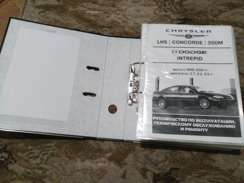
Руководство по техническому обслуживанию и ремонту автомобилей Chrysler 300M/Concorde/LHS и Dodge Intrepid 1998-2001 годов выпуска.
- Автор: —
- Издательство: Легион-Автодата
- Год издания: —
- Страниц: 380
- Формат: —
- Размер: —

-
Contents
-
Table of Contents
-
Bookmarks
Quick Links
IN
Introduction
0
Lubrication & Maintenance
2
Suspension
3
Driveline
5
Brakes
7
Cooling
8A
Audio
8B
Chime/Buzzer
8C
Clock
8E
Electronic Control Modules
8F
Engine Systems
8FS
Engine Systems
8G
Heated Systems
8H
Horn
8I
Ignition Control
8J
Instrument Cluster
8L
Lamps
8LS
Lamps
8M
Message Systems
8N
Power Systems
8NS
Power Systems
NOTE: For New Vehicle Preparation information, see the separate
publication, 81-170-00003.
NOTE: Group names with the suffix S indicate groups pertaining to
Police Vehicles.
GROUP TAB LOCATOR

8OS
8P
8Q
8R
8W
9
11
13
14
19
21
22
23
23S
24
25
Restraints
Restraints
Speed Control
Vehicle Theft Security
Wipers/Washers
Wiring
Engine
Exhaust System
Frame & Bumpers
Fuel System
Steering
Transaxle
Tires/Wheels
Body
Body
Heating & Air Conditioning
Emissions Control
Component and System Index
Component and System Index-Police Package
Service Manual Comment Forms
Chapters
Summary of Contents for Dodge Intrepid
- Manuals
- Brands
- Dodge Manuals
- Automobile
- Intrepid
Manuals and User Guides for Dodge Intrepid. We have 2 Dodge Intrepid manuals available for free PDF download: Service Manual, Serveice Manual

Dodge Intrepid Service Manual (1050 pages)
dodge intrepid
Brand: Dodge
|
Category: Automobile
|
Size: 29.66 MB
Table of Contents
-
Table of Contents
94
-
Body Code Plate
2
-
Location and Decoding
2
-
Description
4
-
Fastener Identification
4
-
Description Description — Fastener Usage
7
-
Metric System Description
8
-
Digit
11
-
Vehicle Safety Certification Label
12
-
C101
103
-
C104
105
-
C105
105
-
C106
106
-
C120 (Police Package/Special Service)
109
-
C200
110
-
C201
111
-
C204
113
-
C300
115
-
C301
116
-
C302
117
-
C303
118
-
C304
119
-
C305
119
-
C306
120
-
C307
120
-
C308
121
-
C309
121
-
C310
122
-
C311
122
-
C312
122
-
C313 (Concorde/Dodge/300M)
123
-
C313 (Ltd/Built-Up-Export) — (Tail Lamps
123
-
C313 (Ltd/Concorde/Built-Up-Export)
123
-
C314 (Concorde/Dodge/300M)
124
-
C314 (Ltd/Built-Up-Export) — (Tailamps
124
-
C314 (Ltd/Concorde/Built-Up-Export)
124
-
C315 (Concorde/Ltd)
125
-
C316
125
-
C317
126
-
C319 (Memory)
128
-
C320 (Concorde/Ltd)
128
-
Grounds
205
-
Splices
206
-
-
-
8W-97 Power Distribution
230
-
Cigar Lighter/Power Outlet Description
231
-
Operation
232
-
Removal
232
-
Installation
232
-
-
Power Distribution
231
-
Description
231
-
Operation
231
-
Standard Procedure — Cigar Lighter/ Power Outlet Customer Preference
231
-
-
Iod Fuse Description
232
-
Operation
233
-
Removal
233
-
Installation
233
-
-
Junction Block Description
233
-
Operation
234
-
Removal
234
-
Installation
234
-
-
Power Distribution Center Description
234
-
Removal
235
-
Installation
235
-
-
-
Engine
236
-
Engine 2.7L
238
-
Engine 2.7L Description
238
-
Diagnosis and Testing
240
-
Diagnosis and Testing — Engine
240
-
Diagnosis — Introduction
240
-
Diagnosis and Testing — Engine Diagnosis — Performance
241
-
Diagnosis and Testing — Engine Diagnosis — Mechanical
243
-
Diagnosis and Testing — Cylinder Compression Pressure Test
245
-
Diagnosis and Testing — Cylinder Combustion Pressure Leakage Test
245
-
-
Standard Procedure Standard Procedure — Form-In- Place Gaskets and Sealers
246
-
Standard Procedure — Engine Gasket Surface Preparation
246
-
Standard Procedure — Engine Core and Oil Gallery Plugs
247
-
Standard Procedure — Repair of Damaged or Worn Threads
247
-
Standard Procedure — Hydrostatic Locked Engine
248
-
Standard Procedure — Measuring Bearing Clearance Using Plastigage
248
-
-
Removal — Engine Assembly
248
-
Installation — Engine Assembly
250
-
Specifications
252
-
2.7L Engine
252
-
Torque
254
-
-
Special Tools
255
-
2.7L Engine
255
-
-
-
-
Air Cleaner Element Removal
258
-
Engine 3.5L
258
-
Installation
258
-
-
Cylinder Head
259
-
Description
259
-
Diagnosis and Testing-Cylinder Head Gasket
259
-
Removal
260
-
Cleaning
261
-
Inspection
262
-
Installation
262
-
-
Camshaft(S) Description
263
-
Operation
263
-
Standard Procedure — Camshaft End Play
263
-
-
Removal
263
-
Inspection
263
-
Installation
264
-
-
Cylinder Head Cover(S) Removal
265
-
Installation
266
-
-
Intake/Exhaust Valves & Seats Description
266
-
Operation
266
-
Standard Procedure — Valve and Valve Seat Refacing
266
-
Removal
267
-
Inspection
268
-
Installation
268
-
-
Valve Springs Description
269
-
Operation
269
-
Removal
269
-
Removal — in Vehicle
269
-
Removal — off Vehicle
269
-
-
Inspection
269
-
Installation
270
-
Installation — in Vehicle
270
-
Installation — off Vehicle
271
-
-
-
Valve Stem Seals Removal
271
-
Installation
272
-
-
Hydraulic Lash Adjusters
272
-
Diagnosis and Testing — Hydraulic
272
-
Lash Adjuster Noise Diagnosis
272
-
-
Removal
273
-
Installation
273
-
-
Rocker Arms Description
273
-
Operation
273
-
Inspection
274
-
Installation
274
-
-
Engine Block Description
274
-
Standard Procedure — Cylinder Bore Honing
274
-
Cleaning
274
-
-
Connecting Rod Bearings
276
-
Standard Procedure — Connecting
276
-
Rod and Bearing Fitting
276
-
-
-
Crankshaft Description
277
-
Operation
277
-
Standard Procedure — Crankshaft End Play
277
-
Removal
277
-
Installation
278
-
-
Crankshaft Main Bearings Standard Procedure — Crankshaft Main Bearing Fitting
280
-
Crankshaft Oil Seal — Front
282
-
Removal
282
-
Installation
282
-
-
Crankshaft Oil Seal — Rear
283
-
Removal
283
-
Installation
283
-
-
Crankshaft Rear Oil Seal Retainer
284
-
Removal
284
-
Installation
284
-
Assembly
306
-
Installation
306
-
-
-
Intake Manifold Description
307
-
Operation
307
-
Diagnosis and Testing — Intake Manifold Leaks
307
-
-
Intake Manifold — Upper
307
-
Standard Procedure — Intake
307
-
Manifold Vacuum Port Repair
307
-
-
Removal — Upper
307
-
Inspection
308
-
Installation
308
-
-
Intake Manifold — Lower Removal
309
-
Inspection
309
-
Installation
309
-
-
Exhaust Manifold Description
310
-
Exhaust Manifold — Right Removal
310
-
Inspection
310
-
Installation
310
-
-
Exhaust Manifold — Left Removal
311
-
Inspection
311
-
Installation
311
-
-
Valve Timing
311
-
Description
311
-
Standard Procedure Engine Timing — Verification
313
-
-
Timing Chain Cover Removal
313
-
Installation
314
-
-
-
Engine 3.5L
322
-
Description
325
-
Timing Belt/Chain and Sprockets Removal Removal — Timing Chain
314
-
Removal — Crankshaft Sprocket
315
-
Installation Installation — Timing Chain
317
-
Installation — Crankshaft Sprocket
321
-
-
The Cylinders Are Numbered from Front to Rear
325
-
With the Right Bank Odd Numbered, and the Left Bank
325
-
Even Numbered (Fig. 2). the Firing Order Is
325
-
The Engine Identification Number Is Located on the
325
-
Engine 3.5L Description
325
-
Diagnosis and Testing Diagnosis and Testing — Engine Diagnosis — Introduction
325
-
Diagnosis and Testing — Engine Diagnosis — Mechanical
327
-
Diagnosis and Testing — Engine Diagnosis — Performance
329
-
Diagnosis and Testing — Cylinder Compression Pressure Test
331
-
Diagnosis and Testing — Cylinder Combustion Pressure Leakage Test
331
-
-
Standard Procedure Standard Procedure — Form-In- Place Gaskets and Sealers
331
-
Standard Procedure — Engine Gasket Surface Preparation
332
-
Standard Procedure — Repair of Damaged or Worn Threads
332
-
Standard Procedure — Hydrostatic Locked Engine
333
-
Standard Procedure — Engine Core and Oil Gallery Plugs
333
-
Standard Procedure — Measuring Bearing Clearance Using Plastigage
334
-
-
Removal — Engine Assembly
334
-
Installation — Engine Assembly
335
-
Specifications
337
-
3.5L Engine
337
-
Torque
340
-
-
Special Tools
341
-
3.5L Engine
341
-
-
-
-
-
Air Cleaner Element Removal
344
-
Installation
344
-
-
Cylinder Head Description
344
-
Diagnosis and Testing-Cylinder Head Gasket
344
-
Removal
345
-
Cleaning
345
-
Inspection
346
-
Installation
346
-
-
Camshaft Oil Seal(S) Removal
347
-
Installation
348
-
-
Camshaft(S) Description
348
-
Operation
348
-
Standard Procedure — Measuring Camshaft End Play
348
-
-
Removal
349
-
Cleaning
349
-
Inspection
349
-
Installation
349
-
-
Cylinder Head Cover(S) Removal
350
-
Installation
350
-
-
Intake/Exhaust Valves & Seats Description
351
-
Operation
351
-
Standard Procedure — Valve and Valve Seat Refacing
351
-
Removal
352
-
Cleaning
352
-
Inspection Inspection — Valves
353
-
Inspection — Valve Guides
353
-
-
Installation
353
-
-
Rocker Arm / Adjuster Assembly Description Description — Rocker Arm
354
-
Description — Rocker Arm Shafts
354
-
Operation
354
-
Diagnosis and Testing Lash Adjuster (Tappet) Noise Diagnosis
354
-
Standard Procedure — Hydraulic Lash Adjuster Bleeding
356
-
Removal
356
-
Disassembly
357
-
Inspection
357
-
Assembly
358
-
Installation
358
-
-
Spark Plug Tube Removal
359
-
Installation
359
-
-
Valve Stem Seals Removal
359
-
Valve Springs Description
360
-
Operation
360
-
Removal
360
-
Removal — Cylinder Head off
360
-
Removal — Cylinder Head on
360
-
-
Inspection
361
-
Installation
361
-
Installation — Cylinder Head off
361
-
Installation — Cylinder Head on
362
-
-
-
Engine Block Description
362
-
Standard Procedure — Cylinder Bore Honing
362
-
Cleaning
363
-
Inspection
363
-
-
Connecting Rod Bearings
364
-
Crankshaft Description
365
-
Operation
365
-
Standard Procedure — Crankshaft End Play
365
-
Removal
365
-
Inspection
366
-
Installation
367
-
-
Crankshaft Main Bearings Standard Procedure — Crankshaft Main Bearing Fitting
368
-
Removal
369
-
Installation
370
-
-
Crankshaft Oil Seal — Front Removal
371
-
Installation
371
-
-
Crankshaft Oil Seal — Rear Removal
372
-
Installation
372
-
-
Crankshaft Rear Oil Seal Retainer Removal
373
-
Installation
373
-
-
Flex Plate Removal
374
-
Installation
374
-
-
Piston & Connecting Rod Description
374
-
Operation
374
-
Standard Procedure — Fitting Pistons
374
-
Removal
374
-
Installation
375
-
-
Piston Rings
377
-
Standard Procedure — Piston Ring Fitting
377
-
Removal
377
-
Installation
378
-
-
Structural Collar / Cover Removal
379
-
Installation
379
-
-
Vibration Damper Removal
380
-
Installation
380
-
Removal
381
-
-
Engine Mounting Description
381
-
Inspection
381
-
-
Left Mount Removal
381
-
Installation
381
-
-
Rear Mount Removal
382
-
Installation
382
-
-
Right Mount Removal
382
-
Lubrication Description
383
-
Operation
383
-
Diagnosis and Testing Diagnosis and Testing — Engine Oil Leak Inspection
383
-
Diagnosis and Testing — Checking Engine Oil Pressure
384
-
-
-
Oil Description
385
-
Standard Procedure Standard Procedure — Engine Oil Level Check
385
-
Standard Procedure — Engine Oil and Filter Change
385
-
-
-
Oil Cooler & Lines Description
386
-
Operation
386
-
Removal
386
-
Installation
387
-
-
Oil Filter Removal
387
-
Oil Pan Removal
387
-
Installation
388
-
-
Oil Pressure Relief Valve Removal
389
-
Inspection
389
-
Installation
389
-
-
Oil Pressure Switch Description
389
-
Description
389
-
Operation
389
-
Removal
389
-
Installation
390
-
-
Oil Pump Removal
390
-
Disassembly
390
-
Cleaning
390
-
Inspection
390
-
Assembly
393
-
Installation
393
-
-
-
Intake Manifold Description
393
-
Diagnosis and Testing — Intake Manifold Leaks
394
-
-
Intake Manifold — Upper Removal
394
-
Inspection
395
-
Installation
396
-
-
Intake Manifold — Lower Removal
396
-
Inspection
397
-
Installation
397
-
-
Exhaust Manifold Description
399
-
Exhaust Manifold — Right Removal
400
-
Inspection
400
-
Installation
400
-
-
Exhaust Manifold — Left Removal
400
-
Inspection
401
-
Installation
401
-
Valve Timing Description
401
-
Standard Procedure — Valve Timing
401
-
Verification
401
-
-
Timing Belt Cover(S) — Front Removal
402
-
Timing Belt Cover(S) — Rear Removal
403
-
Installation
403
-
-
Timing Belt Tensioner & Pulley Removal Removal — Tensioner Pulley Assembly
405
-
Removal — Tensioner
405
-
Inspection — Tensioner Pulley Assembly
405
-
Inspection — Tensioner
405
-
Installation Installation — Tensioner Pulley Assembly
405
-
Installation — Tensioner
406
-
-
-
Timing Belt and Sprockets Removal Removal — Timing Belt
406
-
Removal — Camshaft Sprockets
407
-
Removal — Crankshaft Sprocket
409
-
Inspection — Timing Belt
409
-
Installation Installation — Timing Belt
409
-
Installation — Camshaft Sprockets
410
-
Installation — Crankshaft Sprocket
412
-
-
-
-
Engine 2.7L
325
-
-
Exhaust System
414
-
Exhaust System
416
-
Inspection
417
-
Installation — Exhaust System
417
-
Removal — Exhaust System
417
-
Adjustments
418
-
Specifications Torque
418
-
Catalytic Converter(S) Description
419
-
Operation
419
-
Inspection
420
-
-
-
Exhaust System
419
-
Special Tools
419
-
Catalytic Converter — Right
420
-
Removal — Right Side
420
-
Installation — Right Side
421
-
-
Heat Shields Description
421
-
Operation
421
-
-
Catalytic Converter — Left
421
-
Removal — Left Side
421
-
Installation — Left Side
421
-
-
Muffler/Front Resonator Assembly Removal
422
-
Installation
422
-
-
Resonator — Left Rear Removal
422
-
Resonator — Right Rear (300M Special) Removal
422
-
-
-
Frame & Bumpers
424
-
Front Fascia Removal Removal
425
-
Front Bumper Reinforcement
425
-
Installation Installation
425
-
Installation — Intrepid
426
-
-
Removal — Intrepid
425
-
Rear Bumper Removal
426
-
Installation
427
-
-
Rear Fascia
427
-
Removal
427
-
Removal — Intrepid
427
-
-
Rear Fascia — Intrepid Installation — Intrepid
427
-
Frame Specifications Frame Dimensions
428
-
Specifications — Torque
432
-
-
Engine Cradle Crossmember Removal
432
-
Installation
432
-
-
Rear Crossmember Description
433
-
Operation
433
-
Removal
433
-
Disassembly
435
-
Assembly
436
-
Installation
436
-
-
Front Tow Hook Bracket Removal
433
-
Front Tow Eye Removal
433
-
Installation
433
-
-
Rear Tow Eye Removal
438
-
Installation
438
-
-
-
Installation
425
-
-
Fuel System
440
-
Fuel Delivery Description
441
-
Diagnosis and Testing — Fuel Delivery System
441
-
Fuel Delivery
441
-
Operation
441
-
Standard Procedure
441
-
Standard Procedure — Fuel System
441
-
Pressure Release Procedure
441
-
Standard Procedure — Draining Fuel Tank
441
-
Torque
442
-
Fuel System Pressure
442
-
Fuel Tank Capacity
442
-
-
Special Tools
442
-
Fuel
442
-
-
Fuel Level Sending Unit / Sensor Description
443
-
Removal
443
-
Installation
445
-
-
Flow Management Valve Description
443
-
Operation
443
-
-
Fuel Lines
445
-
Description — Fuel Lines/Hoses and Clamps
445
-
Standard Procedure — Hoses and Clamp
445
-
-
Fuel Pressure Regulator Description
446
-
Operation
446
-
Removal
446
-
Installation
446
-
-
Fuel Pump Module Description
447
-
Removal
448
-
Installation
448
-
-
Fuel Pump Description
447
-
Operation
447
-
-
Fuel Rail Description
449
-
Operation
449
-
Removal — 2.7/3.5L
449
-
Installation Installation — 2.7L
449
-
Installation — 3.5L
450
-
-
Fuel Tank Description
450
-
Operation
450
-
Removal
450
-
Installation
452
-
-
Fuel Tank Filler Tube Removal
453
-
Installation
453
-
-
Fuel Tank Vent Tube Removal
453
-
Inlet Filter Removal
453
-
Quick Connect Fitting Standard Procedure — Quick-Connect Fittings
454
-
-
-
Fuel Injection
457
-
Fuel Injection
458
-
Operation — Injection System
458
-
Operation — Modes of Operation
458
-
FUEL CORRECTION or ADAPTIVE MEMORIES
460
-
Programmable Communications Interface (Pci) Bus
461
-
Specifications Torque
462
-
Torque Management
462
-
Accelerator Pedal
463
-
Removal
463
-
Installation
464
-
-
Special Tools
463
-
Fuel
463
-
-
Crankshaft Position Sensor
464
-
Description
464
-
Operation
465
-
Removal
465
-
Installation
465
-
-
Engine Speed Sensor Description
465
-
Fuel Injector Description
466
-
Operation
466
-
Removal Removal — 2.7L
466
-
Removal — 3.5L
467
-
-
Installation Installation — 2.7L
467
-
Installation — 3.5L
467
-
-
-
Fuel Pump Relay Description
467
-
Operation
467
-
-
Idle Air Control Motor Description
468
-
Operation
468
-
Removal Removal — 2.7L
468
-
Removal — 3.5L
468
-
Installation Installation — 2.7L
468
-
Installation — 3.5L
469
-
-
-
Intake Air Temperature Sensor Removal
469
-
Installation
469
-
-
Map Sensor Description
469
-
Operation
470
-
Removal Removal — 2.7L
471
-
Removal — 3.5L
471
-
-
Installation Installation — 2.7L
471
-
Installation — 3.5L
471
-
-
O2 Sensor Description
471
-
Operation
472
-
Removal — Upstream 1/1, 2/1
473
-
Removal — Downstream 1/2, 2/2
473
-
-
Installation Installation — Upstream
474
-
Installation — Downstream 1/2, 2/2
474
-
-
-
-
Manifold Tune Valve Removal — 3.5L
469
-
O2 Sensor
472
-
Short Runner Valve Description
474
-
Operation
474
-
Removal — 3.5L
474
-
Installation — 3.5L
474
-
-
Throttle Body Description
475
-
Operation
475
-
Removal Removal — 2.7L
475
-
Removal — 3.5L
475
-
-
Installation Installation — 2.7L
476
-
Installation — 3.5L
476
-
-
-
Throttle Control Cable Removal
476
-
Installation
476
-
-
Throttle Position Sensor Description
476
-
Operation
476
-
Removal — 2.7L
477
-
Removal — 3.5L
477
-
Installation — 2.7L
477
-
Installation — 3.5L
477
-
-
-
-
-
Steering
478
-
Diagnosis and Testing Diagnosis and Testing — Power Steering Flow and Pressure Test
479
-
Diagnosis and Testing — Steering Diagnosis Charts
481
-
Diagnosis and Testing — Speed Proportional Power Steering
486
-
Power Steering Fastener Torque
486
-
Specifications
486
-
Power Steering
487
-
Special Tools
487
-
-
Column
488
-
Column
489
-
Operation
500
-
Diagnosis and Testing — Steering
500
-
-
-
Ignition Switch Removal
500
-
Intermediate Shaft
500
-
Column Intermediate Shaft
500
-
-
Key/Lock Cylinder Description
501
-
Operation
501
-
Removal
501
-
-
Steering Coupling
502
-
Diagnosis and Testing — Steering
502
-
Column Shaft Upper Coupler
502
-
Removal
502
-
-
Steering Wheel Removal
503
-
Installation
503
-
-
Steering Column Gear Shift Lever Removal
503
-
-
-
Table of Contents
507
-
Operation — Power Steering Gear
509
-
Operation — Speed Proportional Steering Gear
509
-
Removal — Power Steering Gear
509
-
Steering Gear
509
-
Assembly- Power Steering Gear (Housing Bushings)
515
-
Disassembly — Power Steering Gear (Housing Bushings)
515
-
Installation — Power Steering Gear
515
-
Description — Solenoid Control Valve
517
-
Operation — Solenoid Control Valve
517
-
Removal — Solenoid Control Valve
517
-
-
Speed Proportional Steering Solenoid
517
-
Installation — Solenoid Control Valve
518
-
Tie Rod — Inner
519
-
Removal — Inner Tie Rod
519
-
Installation — Inner Tie Rod
521
-
-
Tie Rod — Outer
522
-
Diagnosis and Testing — Outer Tie Rod Socket End Play
522
-
Removal — Outer Tie Rod
523
-
Installation — Outer Tie Rod
523
-
-
Bushing — Inner Tie Rod
524
-
Removal — Inner Tie Rod Bushing
524
-
Installation — Inner Tie Rod Bushing
527
-
-
-
-
Fluid Cooler Description/Assembly — Pump (Pulley)
530
-
Pump
531
-
Operation
531
-
Standard Procedure — Power Steering Pump Initial Operation
531
-
Removal — Pump (2.7L Engine)
532
-
Removal — Pump (3.5L Engine)
533
-
-
Assembly — Pump (Pulley)
535
-
Installation — Pump (2.7L Engine)
536
-
Installation — Pump (3.5L Engine)
536
-
-
Disassembly — Pump (Pulley)
535
-
Specifications
536
-
Power Steering Pump Flow
536
-
-
Fluid Cooler Description
537
-
Standard Procedure — Power Steering Fluid Level Checking
537
-
Installation
538
-
Removal
538
-
-
Hoses Description
539
-
Removal — Pressure and Return Hoses
539
-
Installation — Pressure and Return Hoses
543
-
Removal — Reservoir (2.7L Engine)
544
-
Removal — Reservoir (3.5L Engine)
544
-
Installation — Reservoir
545
-
Engine)
545
-
Installation — Reservoir (3.5L Engine)
546
-
-
-
-
-
Transaxle
548
-
42Le Automatic Transaxle
550
-
Diagnosis and Testing
551
-
Diagnosis and Testing — Hydraulic
552
-
Pressure Tests
555
-
Diagnosis and Testing — Clutch Air Pressure Tests
555
-
Diagnosis and Testing — Fluid Leakage
556
-
-
Operation
551
-
Removal
557
-
Standard Procedure — Aluminum Thread Repair
557
-
Disassembly
558
-
Assembly
575
-
Installation
594
-
Schematics and Diagrams — 42Le Transaxle
595
-
Specifications
608
-
42Le Automatic Transaxle
608
-
-
Special Tools
610
-
42Le Automatic Transaxle
610
-
-
Accumulator Description
616
-
Autostick Switch Description
617
-
Bearing Adjustment Procedures
618
-
Master Shim Chart
618
-
-
Driving Clutches Description
620
-
Final Drive
620
-
Disassembly
620
-
Assembly / Bearing Adjustment Procedure
628
-
Standard Procedure — Fluid/Filter Service
645
-
Standard Procedure — Differential Sump Drain and Refill
646
-
-
-
Gear Shift Cable — Column Removal
647
-
Installation
649
-
Adjustment
650
-
-
-
Gear Shift Cable — Floor Removal
651
-
Installation
651
-
Adjustment
653
-
-
-
Holding Clutches Description
653
-
Input Clutch Assembly Disassembly
654
-
Assembly
661
-
-
Oil Pump Description
671
-
Standard Procedure — Oil Pump Volume Check
671
-
Disassembly
672
-
Assembly
673
-
-
Planetary Geartrain Description
673
-
Seal — Stub Shaft (Long) Removal
674
-
Installation
675
-
-
Seal — Stub Shaft (Short) Removal
676
-
Seal — Oil Pump
678
-
Shift Interlock Cable Removal
679
-
Installation
680
-
Adjustment — Interlock Cable
681
-
-
-
Shift Interlock Mechanism Removal
682
-
Installation
682
-
-
Shift Interlock Solenoid Removal
683
-
Installation
684
-
Operation
686
-
Diagnosis and Testing — Brake/ Transmission Shift Interlock System
687
-
-
Shift Mechanism
689
-
Solenoid/Pressure Switch Assy
690
-
Speed Sensor — Input Description
692
-
Speed Sensor — Output Description
693
-
Torque Converter
695
-
Transfer System Inspection
697
-
Drive Sprocket Height Adjustment Procedure
698
-
-
Transmission Control Relay
699
-
Transmission Range Sensor
699
-
Removal
700
-
-
Valve Body Description
701
-
Removal
703
-
Disassembly
705
-
Installation
715
-
Tire Pressure Monitoring
725
-
Wheel Cover
734
-
-
Lock Cylinder
753
-
Door Glass
756
-
Window Regulator
763
-
Front Fender
774
-
Glove Box
783
-
Instrument Panel Assembly
783
-
-
Instrument Panel
788
-
Rear View Mirror
809
-
Sun Visor
811
-
Front Armrest
816
-
-
Front Seat
818
-
Lumbar Support
827
-
Rear Armrest
829
-
Rear Seat Cushion
832
-
-
Glass Panel
842
-
Wind Deflector
846
-
Opening Dimensions
855
-
Heater Core
977
-
-
Fuel Filler Cap
994
-
Pcv Valve
998
-
Torque References Description
1016
-
-
-
-
Advertisement

Dodge Intrepid Serveice Manual (470 pages)
dodge intrepid
Brand: Dodge
|
Category: Automobile
|
Size: 6.66 MB
Advertisement
Related Products
-
Dodge 1500 2006
-
Dodge 1500 2013
-
Dodge 18681 Viper
-
Dodge 18693 Stratus Coupe
-
Dodge 1941 D-19
-
Dodge 1965 Cuctom 880
-
Dodge 1965 Monaco
-
Dodge 1997 Neon WIRING DIAGRAMS
-
Dodge 1997 Ram 1500
Dodge Categories
Automobile
Industrial Equipment
Automobile Parts
Automobile Electronics
Trucks
More Dodge Manuals
инструкцияDodge Intrepid (2004)

TABLE OF CONTENTS
SECTION PAGE
1
INTRODUCTION
…………………………………………………….3
2
THINGS TO KNOW BEFORE STARTING YOUR VEHICLE
………………………7
3
UNDERSTANDING THE FEATURES OF YOUR VEHICLE
……………………….49
4
UNDERSTANDING YOUR INSTRUMENT PANEL
…………………………….83
5
STARTING AND OPERATING
…………………………………………125
6
WHAT TO DO IN EMERGENCIES
………………………………………151
7
MAINTAINING YOUR VEHICLE
……………………………………….165
8
MAINTENANCE SCHEDULES
…………………………………………211
9
IF YOU NEED CONSUMER ASSISTANCE
…………………………………227
10
INDEX
………………………………………………………….237
1
2
3
4
5
6
7
8
9
10
Автомобиль, как любой хоть сколько-нибудь технологически развитый механизм, должен иметь инструкцию, чтобы простые люди знали как с ним обращаться и при этом не сломать, а криворукие ( и/или тупые) вообще к нему не приближались. И такая инструкция у меня была, правда скачанная на умный гаджет. И пользоваться ей не всегда было удобно. Да, да, да я знаю, что ее совсем не сложно купить в оригинале, и стоит она не таких уж больших денег. Но ведь для владельцев LH2 эта книга подобна библии. И при такой важности представляет из себя журнальчик толщиной пару сантиметров. Не солидно как-то.

true original?
Что ж, придам ей немного монументальности. Для начала собрал на работе все черновики формата А4, у которых одна сторона была чистой. Далее чуть не запорол принтер, пытаясь распечатать подряд почти 400 страниц. Ну и убиваем целый вечер на закладывание листов в файлики. Скрепляем все это красивой папкой и любуемся красотой.
Полный размер
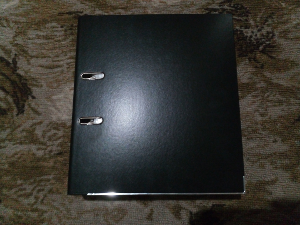
большому черному автомобилю — большая черная книга)
Полный размер
широк размах, как русская душа
Полный размер
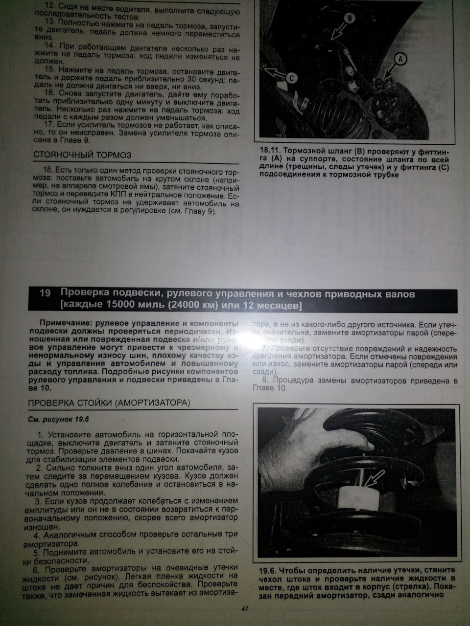
текст читается хорошо, жаль не до всех доходит, что инструкцию читать нужно.
Многие конечно скажут, что я страдаю херней и будут правы. Но такова уж природа психов, — временами начинается обострение бурной деятельности, и ничего с этим не поделаешь. Кстати принтер не пострадал, жив – здоров.) А книжка эта — скорее сувенир для антуража, нежели для работы. Но при необходимости можно отделить часть книги и взять с собой. А ваш оригинальный мануал так может? 