Посмотреть инструкция для BENNING Duspol Expert бесплатно. Руководство относится к категории Без категории, 1 человек(а) дали ему среднюю оценку 7.3. Руководство доступно на следующих языках: русский, английский. У вас есть вопрос о BENNING Duspol Expert или вам нужна помощь? Задайте свой вопрос здесь
Не можете найти ответ на свой вопрос в руководстве? Вы можете найти ответ на свой вопрос ниже, в разделе часто задаваемых вопросов о BENNING Duspol Expert.
Инструкция BENNING Duspol Expert доступно в русский?
Не нашли свой вопрос? Задайте свой вопрос здесь
Указатель напряжения DUSPOL BENNING
ВНИМАНИЕ! Все индикаторы наличия напряжения серии DUSPOL соответствуют международному стандарту DIN VDE 1000В
Международный стандарт на указатели напряжения IEC/EN 61243-3 (DIN VDE 0682-401) повышают безопасность работы электрика с электроустановками и электродвигателями находящимися под напряжением.
Все указатели напряжения используемые в электрических сетях с напряжением до 1000 Вольт должны соответствовать стандарту VDE
Все указатели напряжения серии DUSPOL от компании BENNING оснащены функцией непосредственного вывода измеряемой информации на табло без нажатия кнопок. В случае необходимости с помощью нажатием кнопок может быть подключен измерительный контур который позволяет избежать воздействия паразитных наведенных индуктивного и емкостного напряжения. Таким образом можно четко определить электрическую сеть высокой и малой мощности.
Некоторые индикаторы напряжения DUSPOL имеют функцию вибратора. Сила вибрации увеличивается пропорционально прилагаемому напряжению и является дополнительным показателем величины напряжения.
Индикаторы напряжения DUSPOL® (Оригинальная конструкция)
— безопасное измерение напряжений до 1000 В переменного/постоянного тока
— непосредственный вывод результатов измерений
— подключение низкоомного измерительного контура с помощью кнопок (проверка при малом импедансе)
— независимая от аккумулярного питания индикация напряжения свыше 50 В AC/DC тока
— определение наличия напряжения по вибрации корпуса щупа
— прочный округлый корпус с прорезиненной поверхностью для использования вне помещений (класс защиты IP 65)
— полное соответствие стандарту DIN EN 61243-3 (VDE0682-401):2015
BENNING- измерительное оборудование высшего класса
Приобретая индикаторы напряжения серии DUSPOL от компании BENNING Вы получаете:
* Указатель напряжения сертифицирован и испытан в соответствии со стандартом VDE (работа под напряжением до 1000 В)
* Измерение напряжения при высоком импендансе без нажатия кнопок
* Подключаемый измерительный контур
* Преднамеренное размыкание токового защитного выключателя на 30мА
* Прозвонка цепи с сигнализацией звуковым, световым сигналом или выводом на ЖК-дисплей
* Указатель последовательности чередования фаз с помощью стрелок на дисплее
* Безопасное определение наличия фазы при помощи одного измерительного щупа
* Класс защиты IP64 (ударопрочный, пылезащищенный, брызгозащищенный)
* Автоматическая подсветка ЖК-дисплея по сигналу датчика освещенности
* Безопасное измерение напряжения до 1000 Вольт переменного и постоянного тока (только модель DUSPOL 1000)
* Сохранение результата измерения
* Определение полярности электрического тока «+» или «-«
* Подключение низкоомной измерительной цепи с помощью кнопок
* Индикация напряжения в диапазоне 12-690 Вольт (переменный ток) и 12-750 Вольт (постоянный ток) (замер электрического напряжения возможен даже при отсутствии аккумулятора)
Источник
Login or create an account
Returning Customer
I am a returning customer
Login or create an account
Register Account
If you already have an account with us, please login at the login form.
Ваша учетная запись создана!
Спасибо за регистрацию в BENNING!
Вы будете уведомлены по электронной почте, как только Ваш Личный Кабинет будет активирован администрацией магазина.
Если у Вас есть какие-то вопросы, пожалуйста напишите нам.
Выход
Вы вышли из Личного Кабинета.
Ваша корзина покупок была сохранена. Она будет восстановлена при следующем входе в Ваш Личный Кабинет.


050261 Указатель напряжения DUSPOL analog BENNING
050261 Указатель напряжения DUSPOL analog BENNING
Сохранение результатов измерения
Однополюсная проверка фаз: символ «R» для переменного напряжения
Проверка прохождения и полупроводников
Индикация напряжения 12 В — 1000 В переменного / постоянного тока (LED / плунжер)
Отображение уровней: 12, 24, 50, 120, 230, 400, 690, 1000 В переменного / постоянного тока
Проверка полярности (плюс/минус) постоянного напряжения
Проверка УЗО 30 мА при помощи кнопки
Подключение к нагрузке двумя клавишными переключателями с мембранами
Вибрационный сигнал тревоги для безопасного распознавания напряжения
Ударопрочный, пыленепроницаемый, брызгозащищенный корпус (класс защиты IP 65)
- Вывод результатов измерений: плунжер/ светодиод
- Диапазон измерения напряжения: 12 — 1000V AC / DC
- прозвонка: нет
- последовательность чередования фаз: есть/ЖК дисплей
- однофазная проверка фазы: есть/ЖК дисплей
- определение полярности: есть/ЖК дисплей
- подключение нагрузки при помощи кнопок: IS = 600 мA (1000 В)
- проверка УЗО 30 мA при помощи кнопок: есть
- вибрация: есть
- подсветка места измерения: нет
- Габаритные размеры (Д x Ш) 330 x 85 мм
- класс защиты: IP 65
- Класс перегрузок CAT IV 600 V, CAT III 1000 V
- Соответствие стандартам: IEC/EN 61243-3, DIN VDE 0682-401:2011-02
- Одобрено VDE / GS: да
Источник
Указатель напряжения DUSPOL BENNING
ВНИМАНИЕ! Все индикаторы наличия напряжения серии DUSPOL соответствуют международному стандарту DIN VDE 1000В
Международный стандарт на указатели напряжения IEC/EN 61243-3 (DIN VDE 0682-401) повышают безопасность работы электрика с электроустановками и электродвигателями находящимися под напряжением.
Все указатели напряжения используемые в электрических сетях с напряжением до 1000 Вольт должны соответствовать стандарту VDE
Все указатели напряжения серии DUSPOL от компании BENNING оснащены функцией непосредственного вывода измеряемой информации на табло без нажатия кнопок. В случае необходимости с помощью нажатием кнопок может быть подключен измерительный контур который позволяет избежать воздействия паразитных наведенных индуктивного и емкостного напряжения. Таким образом можно четко определить электрическую сеть высокой и малой мощности.
Некоторые индикаторы напряжения DUSPOL имеют функцию вибратора. Сила вибрации увеличивается пропорционально прилагаемому напряжению и является дополнительным показателем величины напряжения.
Индикаторы напряжения DUSPOL® (Оригинальная конструкция)
— безопасное измерение напряжений до 1000 В переменного/постоянного тока
— непосредственный вывод результатов измерений
— подключение низкоомного измерительного контура с помощью кнопок (проверка при малом импедансе)
— независимая от аккумулярного питания индикация напряжения свыше 50 В AC/DC тока
— определение наличия напряжения по вибрации корпуса щупа
— прочный округлый корпус с прорезиненной поверхностью для использования вне помещений (класс защиты IP 65)
— полное соответствие стандарту DIN EN 61243-3 (VDE0682-401):2015
BENNING- измерительное оборудование высшего класса
Приобретая индикаторы напряжения серии DUSPOL от компании BENNING Вы получаете:
* Указатель напряжения сертифицирован и испытан в соответствии со стандартом VDE (работа под напряжением до 1000 В)
* Измерение напряжения при высоком импендансе без нажатия кнопок
* Подключаемый измерительный контур
* Преднамеренное размыкание токового защитного выключателя на 30мА
* Прозвонка цепи с сигнализацией звуковым, световым сигналом или выводом на ЖК-дисплей
* Указатель последовательности чередования фаз с помощью стрелок на дисплее
* Безопасное определение наличия фазы при помощи одного измерительного щупа
* Класс защиты IP64 (ударопрочный, пылезащищенный, брызгозащищенный)
* Автоматическая подсветка ЖК-дисплея по сигналу датчика освещенности
* Безопасное измерение напряжения до 1000 Вольт переменного и постоянного тока (только модель DUSPOL 1000)
* Сохранение результата измерения
* Определение полярности электрического тока «+» или «-«
* Подключение низкоомной измерительной цепи с помощью кнопок
* Индикация напряжения в диапазоне 12-690 Вольт (переменный ток) и 12-750 Вольт (постоянный ток) (замер электрического напряжения возможен даже при отсутствии аккумулятора)
Источник
Login or create an account
Returning Customer
I am a returning customer
Login or create an account
Register Account
If you already have an account with us, please login at the login form.
Ваша учетная запись создана!
Спасибо за регистрацию в BENNING!
Вы будете уведомлены по электронной почте, как только Ваш Личный Кабинет будет активирован администрацией магазина.
Если у Вас есть какие-то вопросы, пожалуйста напишите нам.
Выход
Вы вышли из Личного Кабинета.
Ваша корзина покупок была сохранена. Она будет восстановлена при следующем входе в Ваш Личный Кабинет.


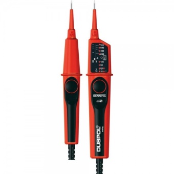
050262 Указатель напряжения DUSPOL expert BENNING
050262 Указатель напряжения DUSPOL expert BENNING
Сохранение результатов измерения
Однополюсная проверка фаз: зеленый светодиод (левая / правая)
Проверка прохождения и полупроводников
Индикация напряжения 12 В — 1000 В переменного / постоянного тока (LED)
Отображение уровней: 12, 24, 50, 120, 230, 400, 690, 1000 В переменного / постоянного тока
Проверка полярности (плюс/минус) постоянного напряжения
Проверка УЗО 30 мА при помощи кнопки
Подключение к нагрузке двумя клавишными переключателями с мембранами
Вибрационный сигнал тревоги для безопасного распознавания напряжения
Удобная подсветка места измерения
Ударопрочный, пыленепроницаемый, брызгозащищенный корпус (класс защиты IP 65)
Характеристики:
Вывод результатов измерений: светодиоды
Диапазон измерения напряжения: 12 — 1000V AC / DC
Прозвонка: звуковой сигнал и светодиод 100 кОм
Последовательность чередования фаз: есть
Подключение нагрузки при помощи кнопок: IS = 550 мA (1000 В)
Проверка УЗО 30 мA при помощи кнопок: есть
Вибрация: есть
Подсветка места измерения: нет
Габаритные размеры (Д x Ш) 330 x 85 мм
Питание 2 x 1,5 V батарейки (LR03/ AAA)
Класс защиты: IP 65
Класс электробезопасности CAT IV 600 V, CAT III 1000 V
Соответствие стандартам: IEC/EN 61243-3, DIN VDE 0682-401:2011-02
Одобрено VDE / GS: да
Источник
Индикатор напряжения (тестер) Benning DUSPOL analog 050261
Индикатор напряжения Benning DUSPOL analog 050261
Контрольное оборудование DUSPOL® — индикаторы напряжения
Соответствует норме IEC/EN 61243-3 (DIN VDE 0682-401) CAT IV 600 В CAT III 1000 В .
Вибрационный сигнал тревоги для безопасного распознавания напряжения.
Подключение нагрузки двумя клавишными переключателями с мембранами.
Измерительное место с целью подавления индуктивных и емкостных напряжений нагружается максимальным испытательным током.
Преднамеренное размыкание токового защитного выключателя на 30 мА FI.
Испытание на прохождение посредством зуммера и светодиода или жидкокристаллического дисплея.
Устройство для проверки направления вращения магнитного поля трехфазной сети (жидкокристаллический дисплей).
Безопасная однополюсная проверка фазы.
Точечная подсветка места измерения.
Ударопрочный, пыленепроницаемый, брызгозащищенный корпус (класс защиты IP 65).
Подсветка жидкокристаллического дисплея активируется автоматически посредством светового датчика.
CAT IV 600 В CAT III 1000 В.
Технические характеристики DUSPOL analog
- вывод результатов измерений: Плунжер/светодиод
- диапазон измерений: 12 — 1000 В
- прозвонка: —
- последовательность чередования фаз: есть/ЖК дисплей
- однофазная проверка фазы: есть/ЖК дисплей
- определение полярности: есть/светодиод
- подключение нагрузки при помощи кнопок: Is = 600 мA(=1000 В)
- запуск 30 мA FI при помощи кнопок: есть
- вибрация: есть
- подсветка места измерения: —
- класс защиты: IP 65
- класс перегрузок: CAT IV 600 В CAT III 1000 В
- артикул: 050261
Источник
D
Bedienungsanleitung
Naudojimosi instrukcija
Operating manual
N
Bruksanvisning
F
Mode d’emploi
Gebruiksaanwijzing
E
Manuel de instrucciones
Instrukcja obsługi
Инструкция за експлоатация
Инструкция по
Návod k použití zkoušečky
эксплуатации индикатора
Käyttöohje
напряжения
Οδηγίες χρήσεως
Bruksanvisning
S
Használati utasítás
Kullanma Talimati
H
Istruzioni per l’uso
Priručnik za upotrebu
I
geprüft und zugelassen
BENNING Elektrotechnik & Elektronik GmbH & Co.KG
Münsterstraße 135 — 137 • D — 46397 Bocholt
Telefon ++49 (0) 2871 — 93 — 0 • Fax ++49 (0) 2871 — 93 — 429
www.benning.de • E-Mail: duspol@benning.de
Operating manual
DUSPOL
expert
®
Before using the voltage tester DUSPOL
®
expert:
Please read the operating manual carefully and
always observe the safety instructions!
List of contents:
1.
Safety instructions
2.
Functional description of the voltage tester
2.
3.
Functional test of the voltage tester
The DUSPOL
4.
How to test AC voltages
according to IEC 61243-3 with visual display. As a
4.1 How to test the phase at AC voltage
supplementary device, the voltage tester is equipped
5.
How to test DC voltages
with a phase indication, phase-sequence indication,
5.1 How to test the polarity at DC voltage
measuring point illumination and a continuity check
6.
How to test the phase sequence of a three-
function. The supplementary functions – except the
phase mains
phase indication – are supplied via two replaceable
7.
How to test an electrically conductive
micro batteries (LR 03/ AAA). The signalling of the
connection (continuity check)
continuity check is done optically and acoustically.
8.
Battery replacement
The voltage tester is designed for DC and AC voltage
9.
Technical data
tests within the voltage range of 12 V up to AC 690 V/
10. General maintenance
DC 750 V. It can be used to perform polarity tests in DC
11. Environmental notice
and phase tests in AC. The voltage tester indicates the
phase-sequence provided that the neutral is earthed.
1.
Safety instructions:
The voltage tester consists of the test probes L1
—
Hold the voltage tester only by the insulated
and L2
handles
and
and do not touch the contact
L1
electrodes (probe tips) !
are provided with push buttons . Without pressing
—
Immediately before use: Check the voltage tester
both push buttons, the following voltage steps (AC
for correct operation! (see chapter 3). The voltage
or DC) can be indicated: 24 V+; 24 V-; 50 V; 120 V;
tester must not be used if one or several display
230 V; 400 V; AC 690 V/ DC 750 V. By pressing both
functions fail or if the voltage tester is not ready to
push buttons, the voltage tester switches to a lower
operate (IEC 61243-3)!
internal resistance (suppression of inductive and
—
At operating sites with a high noise level, it has
capacitive voltages). Thus, also the indication of 12 V+
to be checked before use if the test signal can be
and 12 V- is activated. Furthermore, a vibrating motor
perceived.
(motor with a flyweight) is put under voltage. From
—
The voltage tester must be used only within the
approximately 200 V this motor is set in rotation. With
nominal voltage range of 12 V up to AC 690 V/ DC
the voltage increasing, the motor’s speed and vibration
750 V!
increases as well so that additionally by means of the
—
Do not operate the voltage tester with the battery
handle of test probe L2
compartment being open!
estimated roughly (e.g. 230/ 400 V). The duration of
—
The voltage tester complies with protection class
the test with a lower internal resistance of the device
IP 64 and therefore can also be used under wet
(load test) depends on the value of the voltage to
conditions (designed for outdoor use).
be measured. To prevent excessive warming of the
—
For testing, firmly grasp the voltage tester by the
voltage tester, it is equipped with a thermal protection
handles
and
.
(reverse control). With this reverse control, the speed
—
Never connect the voltage tester to voltage for
of the vibrating motor decreases as well.
longer than 30 seconds (maximum permissible
The measuring point illumination can be activated
operating time = 30 s)!
by pressing the push button of test probe L1
—
The voltage tester only operates correctly
For the voltage measurement with ripple (two-pole
within the temperature range of -10 °C up to
measurement), the illumination is activated with
+55 °C at relative air humidity of 20 % up to 96 %.
reduced brightness. The activation of the continuity
—
Do not dismantle the voltage tester!
check can be introduced by bringing together the two
—
Please protect the housing of the voltage tester
contact electrodes .
against contamination and damages!
Display field
—
Please store the voltage tester under dry
The display system consists of high-contrast light-
conditions.
emitting diodes (LED) indicating DC and AC
—
To prevent injuries and discharge of the battery,
voltages in steps of 12; 24; 50; 120; 230; 400; AC
provide the contact electrodes (probe tips) with
690 V/ DC 750 V. The indicated voltages are nominal
the enclosed cover after using the voltage tester!
voltages. With DC voltage, the LEDs also indicate the
Attention:
polarity for 12 V and 24 V (see chapter 5). The 12 V
After maximum load (i.e. after a measurement of 30
LED can only be activated by pressing both push
seconds at AC 690 V/ DC 750 V), the voltage tester
buttons.
must not be used for a duration of 240 seconds!
LC display
The voltage tester is marked with international electric
The LC display serves for the phase test with
symbols and symbols for indication and operation with
alternating current (AC) and indicates the phase-
the following meaning:
sequence of a three-phase mains.
symbol
meaning
3.
Device or equipment for working under
—
voltage
Push button
—
Alternating current (AC)
—
Direct current (DC)
—
Direct and alternating current (DC and
AC)
Push button (manually actuated);
indicates that respective indications
only occur when both push buttons are
actuated
Phase-sequence clockwise
Phase-sequence indication; the phase
Do not use the voltage tester unless all functions are
sequence can only be indicated at 50
operating correctly!
or 60 Hz and in a earthed mains
Check the function of the LC display by single-pole
connection of the contact electrode of the test probe
L1
4.
How to test AC voltages
This
symbol
shows
the
correct
—
The voltage tester must be used only within the
alignment of the batteries to ensure
nominal voltage range of 12 V up to AC 690 V!
correct polarity
—
Never connect the voltage tester to voltage for
longer than 30 seconds (maximum permissible
Signal lamp, optical signal for continuity
operating time = 30 s)!
check
—
Firmly grasp the insulated handles
the test probes L1 and L2.
Buzzer, acoustic signal for continuity
—
Place the contact electrodes of the test probes
check
L1
and L2
against the relevant points of the
unit under test.
Symbol for phase and phase-sequence
—
For AC voltages from 24 V onwards and when
indication (phase-sequence clockwise)
pressing both push buttons (load test) from 12 V
onwards, the LEDs «plus» and «minus» and
light up. Furthermore, all LEDs light until the step
Functional description
value of the applied voltage is reached.
expert is a two-pole voltage tester
®
—
When pressing both push buttons and from
an applied voltage of approx. 200 V onwards, a
vibrating motor is put in rotation inside the test
probe L2
. With the voltage increasing, the
speed of this motor is increasing as well.
Please make sure that you touch the voltage tester at
the insulated handles of test probes L1
only! Do not cover the display and do not touch the
contact electrodes !
4.1 How to test the phase at AC voltage
—
The voltage tester must be used only within the
nominal voltage range of 12 V up to AC 690 V!
—
The phase test is possible in the earthed mains
from 230 V onwards!
and a connecting cable . The test probe
—
Firmly grasp the handle of test probe L1
is equipped with a display . Both test probes
—
Place the contact electrode of test probe L1
against the relevant point of the unit under test.
—
Never connect the voltage tester to voltage for
longer than 30 seconds (maximum permissible
operating time = 30 s)!
—
If the «R» symbol appears on the LC display ,
the tester is in contact with the live phase of an
AC voltage on this point of the unit under test.
Never touch the contact electrode of test probe L2
during the single-pole test (phase test)!
Note:
The reading of the LC display might be impaired
due to unfavorable light conditions, protective clothing
the voltage value can be
or in insulated locations.
Attention:
The absence of voltage can be detected by means of
a bipolar test only.
5.
How to test DC voltages
—
The voltage tester must be used only within the
nominal voltage range of 12 V up to DC 750 V!
—
Never connect the voltage tester to voltage for
.
longer than 30 seconds (maximum permissible
operating time = 30 s)!
—
Firmly grasp the insulated handles
the test probes L1 and L2.
—
Place the contact electrodes of the test probes
L1
and L2
against the relevant points of the
unit under test.
—
For AC voltages from 24 V onwards and when
pressing both push buttons (load test) from 12 V
onwards, the LEDs «plus» and «minus» and
light up. Furthermore, all LEDs light until the step
value of the applied voltage is reached.
—
When pressing both push buttons and from
an applied voltage of approx. 200 V onwards, a
vibrating motor is put in rotation inside the test
probe L2
. With the voltage increasing, the
speed of this motor is increasing as well.
Please make sure that you touch the voltage tester at
the insulated handles of test probes L1
only! Do not cover the display and do not touch the
Functional check
contact electrodes !
The voltage tester must be used only within
the nominal voltage range of 12 V up to
5.1 How to test the polarity at DC voltage
AC 690 V/ DC 750 V!
—
The voltage tester must be used only within the
Never connect the voltage tester to voltage for
nominal voltage range of 12 V up to DC 750 V!
longer than 30 seconds (maximum permissible
—
Never connect the voltage tester to voltage for
operating time = 30 s)!
longer than 30 seconds (maximum permissible
Check the voltage tester for correct function
operating time = 30 s)!
immediately before use!
—
Firmly grasp the insulated handles
Test all functions by means of known voltage
the test probes L1 and L2.
sources.
—
Place the contact electrodes of the test probes
•
For DC voltage tests use e.g. a car battery.
L1
and L2
against the relevant points of the
•
For AC voltage tests use e.g. a 230 V socket.
unit under test.
•
Connect both contact electrodes to test the
—
If LED lights up, the «positive pole» of the unit
continuity check for correct function.
under test is at test probe
•
Check the battery status for the phase-
—
If LED lights up, the «negative pole» of the unit
sequence
indication
by
activating
the
under test is at test probe
measuring point illumination. Replace the
Please make sure that you touch the voltage tester at
batteries, if necessary.
the insulated handles of test probes L1
only! Do not cover the display and do not touch the
contact electrodes !
to an external conductor (phase).
6.
How to test the phase sequence of a three-
phase mains
The required auxiliary voltage is provided by the power
supply (2 x 1.5 V batteries) integrated into test probe
L1
. Check the functional status of the batteries
before measuring by activating the measuring point
and
of
illumination.
—
The voltage tester must be used only within the
nominal voltage range of 12 V up to AC 690 V!
—
The phase-sequence test is possible from 230 V
AC voltage (phase against phase) onwards in a
earthed three-phase mains.
—
Firmly grasp the insulated handles
and
the test probes L1 and L2.
—
Place the contact electrodes of the test probes
L1
and L2
against the relevant points of the
unit under test.
—
The LEDs have to indicate the external conductor
voltage.
—
Never connect the voltage tester to voltage for
longer than 30 seconds (maximum permissible
operating time = 30 s)!
and L2
—
When contacting the two contact electrodes
with two phases of a three-phase mains
connected in clockwise rotation, the LC display
indicates the «R» symbol. If for two phases the
rotation is anti-clockwise, no symbol appears on
the LC display.
The phase-sequence test always requires a counter-
test! If the LC display indicates clockwise rotation
for two phases of a three-phase mains, those two
.
phases must be contacted again with reversed contact
electrodes during the counter-test. There must
be no symbol indicated on the LC display during the
counter-test. If in both cases the LC display indicates
the „R» symbol, the earthing is too weak or the
batteries are empty.
Attention!
In case of empty batteries, „R» indication for
clockwise and anti-clockwise rotation!
Note:
The reading of the LC display might be impaired
due to unfavorable light conditions, protective clothing
or in insulated locations.
7.
How to test an electrically conductive
connection (continuity check)
—
The continuity check must be performed on
the relevant points of a «dead» (not being
under voltage) unit under test. If necessary, the
capacitors must be discharged.
—
The necessary test voltage is supplied by means
of the power supply (2 x 1.5 V batteries) integrated
in the test probe L1
.
—
The test is possible within the range of
0 — 108 kΩ.
and
of
—
Firmly grasp the handles L1
and L2
.
—
Place the test probes L1
and L2
with the
contact electrodes against the relevant points
of the unit under test.
—
When contacting an electrically conductive
connection with the contact electrodes , the
voltage tester gives an acoustic signal and the
signaling LED lights up.
8.
Battery replacement
Do not set the voltage tester under voltage with the
battery compartment being open!
The energy supply for the phase-sequence indication,
illumination and continuity check of the DUSPOL
expert is done by means of two built-in micro batteries
(LR03/ AAA). Battery replacement is necessary as
and L2
soon as illumination does not work anymore. In this
case, the battery voltage is below 2.2 V.
How to replace the batteries:
Take a screw driver and open the battery
compartment (next to the cable outlet) by a
¼-turn in direction of the arrow (counter-clockwise).
The slot is now vertical and the battery compartment
with the batteries can be removed.
Remove the discharged batteries from the battery
compartment. Insert the new batteries with correct
and
of
polarity (see marking) into the battery compartment.
Put the battery compartment with the batteries back
onto the handle and lock it by ¼-turn in clockwise
direction (slot must be horizontal and the marking
points are opposite!). Make sure not to damage the O
ring. If necessary, it has to be replaced.
.
Battery disposal:
Do not dispose of batteries with the household
.
garbage. You as a consumer are legally obliged to
return used batteries. You can return used batteries
and L2
to public collection facilities in your community area
or return them to any retail outlet selling similar
batteries. Avoid using batteries containing dangerous
substances!
9.
Technical data:
—
Guideline for two-pole voltage testers: IEC 61243-3
—
Protection class: IP 64, IEC 60529 (DIN 40050)
IP 64 means: Protection against access to
dangerous parts and protection against solid
impurities, dustproof, (6 — first index). Splash proof,
(4 — second index). Can also be used in case of
precipitation.
—
Nominal voltage range: 12 V to AC 690 V/ DC 750 V
—
Internal resistance, measuring circuit:
220 kΩ, parallel 3.9 nF (1.95 nF)
of
—
Internal resistance, load circuit – both push
buttons actuated!: approx. 3.7 kΩ…(150 kΩ)
—
Current consumption, measuring circuit:
max. I
3.5 mA (690 V) AC/ 3.4 mA (750 V) DC
n
—
Current consumption, load circuit — both push
buttons actuated!: I
0.2 A (750 V)
s
—
Polarity indication: LED +; LED —
(indicating handle = positive polarity)
—
Indicating steps LED: 12 V+*, 12 V-*, 24 V+, 24 V-,
50 V, 120 V, 230 V, 400 V and 690 V (*: only with
both push buttons actuated)
—
max. indicating errors: U
± 15 %, ELV U
— 15 %
n
n
—
Nominal frequency range f: 0 to 60 Hz
Phase and phase-sequence indication 50/ 60 Hz
—
Phase and phase-sequence indication: ≥ U
230 V
n
—
Vibrating motor, starting: ≥ U
230 V
n
—
max. permissible operating time: ED = 30 s (max.
30 seconds), 240 s pause
—
Test current, continuity check: max. 2 μA
—
Testing range, conducting resistance: 0 — 108 kΩ,
—
Sound level acoustic signal: 55 dB
—
Measuring point illumination (in 30 cm): 10 Lux
—
Current consumption measuring point illumination:
46 mA
—
Current consumption continuity check: 83 mA
—
Current
consumption
automatic
switch-on
illumination: 23 mA
—
Battery: 2 x Micro, LR03/ AAA
—
Weight: approx. 200 g
—
Connecting cable length: approx. 900 mm
—
Operating and storing temperature range: -10 °C
to +55 °C (climate category N)
—
Relative air humidity: 20 % to 96 % (climate
category N)
—
Reverse control times (thermal protection):
voltage
time
230 V
30 s
400 V
9 s
750 V
2 s
Attention!
The phase-sequence indication, measuring point
illumination and continuity check do not work anymore,
if the batteries are empty!
Remove the batteries if not using the voltage tester for
a longer period of time!
10. General maintenance:
Clean the exterior of the housing with a clean dry
cloth (exception: special cleansing cloths). Do not use
solvents and/ or abrasives to clean the voltage tester.
Make sure not to contaminate the battery compartment
and the battery contacts with leaking battery
electrolyte. Should such electrolyte contamination or
®
white deposits occur near the battery or the battery
housing, these must also be removed with a dry cloth.
In case of wear or damaging of the O ring of the
battery compartment, the voltage tester does not
comply with the indicated protection class anymore
(protection against dust and water). In this case, the O
ring must be replaced.
The O ring can be ordered under the BENNING piece
number 772897. Moisten a new O ring with glyzerin or
talcum so that the battery compartment can be locked
and unlocked easily.
11. Environmental notice
At the end of the product’s useful life, please
dispose of it at appropriate collection points
provided in your country.
-
Contents
-
Table of Contents
-
Bookmarks
-
ENGLISH, page 6
-
РУССКИЙ, страница 58
-
FRANÇAIS, page 10
-
ESPAÑOL, página 13
-
DEUTSCH, seite 3
-
ITALIANO, pagina 37
-
DUTCH, pagina 47
-
SVENSKA, sida 62
-
POLSKI, strona 51
-
DANSK, side 24
-
SUOMI, sivu 27
-
ČEŠTINA, strana 21
-
NORSK, side 44
-
ΕΛΛΗΝΙΚΆ, σελίδα 30
-
MAGYAR, oldal 34
-
TÜRKÇE, sayfa 68
-
ROMÂNĂ, pagina 54
-
БЪЛГАРСКИ, страница 17
-
LIETUVIŲ, puslapis 41
Quick Links
Benning Elektrotechnik & Elektronik GmbH & Co. KG
Münsterstraße 135 — 137
D — 46397 Bocholt
Phone: +49 (0) 2871 — 93 — 0
Fax: +49 (0) 2871 — 93 — 429
www.benning.de • E-Mail: duspol@benning.de
Bedienungsanleitung
D
Operating manual
Mode d’emploi
F
Manuel de instrucciones
E
Инструкция за експлоатация
Návod k použití zkoušečky
Brugsanvisning
Käyttöohje
Οδηγίες χρήσεως
Használati utasítás
H
Istruzioni per l’uso
I
Naudojimosi instrukcija
Bruksanvisning
N
Gebruiksaanwijzing
Instrukcja obsługi
Instrucţiuni de Utilizare
Инструкция по эксплуатации
индикатора напряжения
Bruksanvisning
S
Upute za rukovanje
1 SRB
Kullanma Talimati
D
A
3 sec.
B
230 V
AC
PE
N
L
C
1000 V
DC
D
230 V
AC
PE
N
L
10/2015
DUSPOL
expert
®
D
1
2
3
4
5
6
7
8
9
J
U1
10/2015
DUSPOL
expert
®
K
L
M
U2
Summary of Contents for Benning duspol expert
D
Bedienungsanleitung
Operating manual
F
Mode d‘emploi
E
Manuel de instrucciones
Инструкция за експлоатация
Návod k použití zkoušečky
Käyttöohje
Οδηγίες χρήσεως
H
Használati utasítás
I
Istruzioni per l’uso
Naudojimosi instrukcija
N
Bruksanvisning
Gebruiksaanwijzing
Instrukcja obsługi
Инструкция по
эксплуатации
индикатора
напряжения
S
Bruksanvisning
Kullanma Talimati
Priručnik za upotrebu
DUSPOL
®
expert
BENNING Elektrotechnik & Elektronik GmbH & Co.KG
Münsterstraße 135 — 137 • D — 46397 Bocholt
Telefon ++49 (0) 2871 — 93 — 0 • Fax ++49 (0) 2871 — 93 — 429
www.benning.de • E-Mail: [email protected]
T.-Nr. 756153.03/ 03-2006
Operating manual
DUSPOL
®
expert
Before using the voltage tester DUSPOL
®
expert:
Please read the operating manual carefully and
always observe the safety instructions!
List of contents:
1. Safety instructions
2. Functional description of the voltage tester
3. Functional test of the voltage tester
4. How to test AC voltages
4.1 How to test the phase at AC voltage
5. How to test DC voltages
5.1 How to test the polarity at DC voltage
6. How to test the phase sequence of a three-
phase mains
7. How to test an electrically conductive
connection (continuity check)
8. Battery replacement
9. Technical data
10. General maintenance
11. Environmental notice
1. Safety instructions:
— Hold the voltage tester only by the insulated
handles
and and do not touch the contact
electrodes (probe tips) !
— Immediately before use: Check the voltage tester
for correct operation! (see chapter 3). The voltage
tester must not be used if one or several display
functions fail or if the voltage tester is not ready to
operate (IEC 61243-3)!
— At operating sites with a high noise level, it has
to be checked before use if the test signal can be
perceived.
— The voltage tester must be used only within the
nominal voltage range of 12 V up to AC 690 V/ DC
750 V!
— Do not operate the voltage tester with the battery
compartment being open!
— The voltage tester complies with protection class
IP 64 and therefore can also be used under wet
conditions (designed for outdoor use).
— For testing, firmly grasp the voltage tester by the
handles and .
— Never connect the voltage tester to voltage for
longer than 30 seconds (maximum permissible
operating time = 30 s)!
— The voltage tester only operates correctly
within the temperature range of -10 °C up to
+55 °C at relative air humidity of 20 % up to 96 %.
— Do not dismantle the voltage tester!
— Please protect the housing of the voltage tester
against contamination and damages!
— Please store the voltage tester under dry
conditions.
— To prevent injuries and discharge of the battery,
provide the contact electrodes (probe tips) with
the enclosed cover after using the voltage tester!
Attention:
After maximum load (i.e. after a measurement of 30
seconds at AC 690 V/ DC 750 V), the voltage tester
must not be used for a duration of 240 seconds!
The voltage tester is marked with international electric
symbols and symbols for indication and operation with
the following meaning:
symbol meaning
Device or equipment for working under
voltage
Push button
Alternating current (AC)
Direct current (DC)
Direct and alternating current (DC and
AC)
Push button (manually actuated);
indicates that respective indications
only occur when both push buttons are
actuated
Phase-sequence clockwise
Phase-sequence indication; the phase
sequence can only be indicated at 50
or 60 Hz and in a earthed mains
This symbol shows the correct
alignment of the batteries to ensure
correct polarity
Signal lamp, optical signal for continuity
check
Buzzer, acoustic signal for continuity
check
Symbol for phase and phase-sequence
indication (phase-sequence clockwise)
2. Functional description
The DUSPOL
®
expert is a two-pole voltage tester
according to IEC 61243-3 with visual display. As a
supplementary device, the voltage tester is equipped
with a phase indication, phase-sequence indication,
measuring point illumination and a continuity check
function. The supplementary functions – except the
phase indication – are supplied via two replaceable
micro batteries (LR 03/ AAA). The signalling of the
continuity check is done optically and acoustically.
The voltage tester is designed for DC and AC voltage
tests within the voltage range of 12 V up to AC 690 V/
DC 750 V. It can be used to perform polarity tests in DC
and phase tests in AC. The voltage tester indicates the
phase-sequence provided that the neutral is earthed.
The voltage tester consists of the test probes L1
and L2
and a connecting cable . The test probe
L1
is equipped with a display . Both test probes
are provided with push buttons
. Without pressing
both push buttons, the following voltage steps (AC
or DC) can be indicated: 24 V+; 24 V-; 50 V; 120 V;
230 V; 400 V; AC 690 V/ DC 750 V. By pressing both
push buttons, the voltage tester switches to a lower
internal resistance (suppression of inductive and
capacitive voltages). Thus, also the indication of 12 V+
and 12 V- is activated. Furthermore, a vibrating motor
(motor with a flyweight) is put under voltage. From
approximately 200 V this motor is set in rotation. With
the voltage increasing, the motor’s speed and vibration
increases as well so that additionally by means of the
handle of test probe L2
the voltage value can be
estimated roughly (e.g. 230/ 400 V). The duration of
the test with a lower internal resistance of the device
(load test) depends on the value of the voltage to
be measured. To prevent excessive warming of the
voltage tester, it is equipped with a thermal protection
(reverse control). With this reverse control, the speed
of the vibrating motor decreases as well.
The measuring point illumination can be activated
by pressing the push button of test probe L1
.
For the voltage measurement with ripple (two-pole
measurement), the illumination is activated with
reduced brightness. The activation of the continuity
check can be introduced by bringing together the two
contact electrodes .
Display field
The display system consists of high-contrast light-
emitting diodes (LED)
indicating DC and AC
voltages in steps of 12; 24; 50; 120; 230; 400; AC
690 V/ DC 750 V. The indicated voltages are nominal
voltages. With DC voltage, the LEDs also indicate the
polarity for 12 V and 24 V (see chapter 5). The 12 V
LED can only be activated by pressing both push
buttons.
LC display
The LC display
serves for the phase test with
alternating current (AC) and indicates the phase-
sequence of a three-phase mains.
3. Functional check
— The voltage tester must be used only within
the nominal voltage range of 12 V up to
AC 690 V/ DC 750 V!
— Never connect the voltage tester to voltage for
longer than 30 seconds (maximum permissible
operating time = 30 s)!
— Check the voltage tester for correct function
immediately before use!
— Test all functions by means of known voltage
sources.
• For DC voltage tests use e.g. a car battery.
• For AC voltage tests use e.g. a 230 V socket.
• Connect both contact electrodes to test the
continuity check for correct function.
• Check the battery status for the phase-
sequence indication by activating the
measuring point illumination. Replace the
batteries, if necessary.
Do not use the voltage tester unless all functions are
operating correctly!
Check the function of the LC display
by single-pole
connection of the contact electrode of the test probe
L1
to an external conductor (phase).
4. How to test AC voltages
— The voltage tester must be used only within the
nominal voltage range of 12 V up to AC 690 V!
— Never connect the voltage tester to voltage for
longer than 30 seconds (maximum permissible
operating time = 30 s)!
— Firmly grasp the insulated handles
and of
the test probes L1 and L2.
— Place the contact electrodes
of the test probes
L1 and L2 against the relevant points of the
unit under test.
— For AC voltages from 24 V onwards and when
pressing both push buttons (load test) from 12 V
onwards, the LEDs “plus” and “minus” and
light up. Furthermore, all LEDs light until the step
value of the applied voltage is reached.
— When pressing both push buttons
and from
an applied voltage of approx. 200 V onwards, a
vibrating motor is put in rotation inside the test
probe L2 . With the voltage increasing, the
speed of this motor is increasing as well.
Please make sure that you touch the voltage tester at
the insulated handles of test probes L1
and L2
only! Do not cover the display and do not touch the
contact electrodes !
4.1 How to test the phase at AC voltage
— The voltage tester must be used only within the
nominal voltage range of 12 V up to AC 690 V!
— The phase test is possible in the earthed mains
from 230 V onwards!
— Firmly grasp the handle of test probe L1
.
— Place the contact electrode
of test probe L1
against the relevant point of the unit under test.
— Never connect the voltage tester to voltage for
longer than 30 seconds (maximum permissible
operating time = 30 s)!
— If the “R” symbol appears on the LC display
,
the tester is in contact with the live phase of an
AC voltage on this point of the unit under test.
Never touch the contact electrode of test probe L2
during the single-pole test (phase test)!
Note:
The reading of the LC display
might be impaired
due to unfavorable light conditions, protective clothing
or in insulated locations.
Attention:
The absence of voltage can be detected by means of
a bipolar test only.
5. How to test DC voltages
— The voltage tester must be used only within the
nominal voltage range of 12 V up to DC 750 V!
— Never connect the voltage tester to voltage for
longer than 30 seconds (maximum permissible
operating time = 30 s)!
— Firmly grasp the insulated handles
and of
the test probes L1 and L2.
— Place the contact electrodes
of the test probes
L1 and L2 against the relevant points of the
unit under test.
— For AC voltages from 24 V onwards and when
pressing both push buttons (load test) from 12 V
onwards, the LEDs “plus” and “minus” and
light up. Furthermore, all LEDs light until the step
value of the applied voltage is reached.
— When pressing both push buttons
and from
an applied voltage of approx. 200 V onwards, a
vibrating motor is put in rotation inside the test
probe L2 . With the voltage increasing, the
speed of this motor is increasing as well.
Please make sure that you touch the voltage tester at
the insulated handles of test probes L1
and L2
only! Do not cover the display and do not touch the
contact electrodes !
5.1 How to test the polarity at DC voltage
— The voltage tester must be used only within the
nominal voltage range of 12 V up to DC 750 V!
— Never connect the voltage tester to voltage for
longer than 30 seconds (maximum permissible
operating time = 30 s)!
— Firmly grasp the insulated handles
and of
the test probes L1 and L2.
— Place the contact electrodes
of the test probes
L1 and L2 against the relevant points of the
unit under test.
— If LED
lights up, the “positive pole” of the unit
under test is at test probe .
— If LED
lights up, the “negative pole” of the unit
under test is at test probe .
Please make sure that you touch the voltage tester at
the insulated handles of test probes L1
and L2
only! Do not cover the display and do not touch the
contact electrodes !
6. How to test the phase sequence of a three-
phase mains
The required auxiliary voltage is provided by the power
supply (2 x 1.5 V batteries) integrated into test probe
L1 . Check the functional status of the batteries
before measuring by activating the measuring point
illumination.
— The voltage tester must be used only within the
nominal voltage range of 12 V up to AC 690 V!
— The phase-sequence test is possible from 230 V
AC voltage (phase against phase) onwards in a
earthed three-phase mains.
— Firmly grasp the insulated handles
and of
the test probes L1 and L2.
— Place the contact electrodes
of the test probes
L1 and L2 against the relevant points of the
unit under test.
— The LEDs have to indicate the external conductor
voltage.
— Never connect the voltage tester to voltage for
longer than 30 seconds (maximum permissible
operating time = 30 s)!
— When contacting the two contact electrodes
with two phases of a three-phase mains
connected in clockwise rotation, the LC display
indicates the “R” symbol. If for two phases the
rotation is anti-clockwise, no symbol appears on
the LC display.
The phase-sequence test always requires a counter-
test! If the LC display
indicates clockwise rotation
for two phases of a three-phase mains, those two
phases must be contacted again with reversed contact
electrodes during the counter-test. There must
be no symbol indicated on the LC display during the
counter-test. If in both cases the LC display indicates
the „R“ symbol, the earthing is too weak or the
batteries are empty.
Attention!
In case of empty batteries, „R“ indication for
clockwise and anti-clockwise rotation!
Note:
The reading of the LC display
might be impaired
due to unfavorable light conditions, protective clothing
or in insulated locations.
7. How to test an electrically conductive
connection (continuity check)
— The continuity check must be performed on
the relevant points of a “dead” (not being
under voltage) unit under test. If necessary, the
capacitors must be discharged.
— The necessary test voltage is supplied by means
of the power supply (2 x 1.5 V batteries) integrated
in the test probe L1 .
— The test is possible within the range of
0 — 108 kΩ.
— Firmly grasp the handles L1
and L2 .
— Place the test probes L1
and L2 with the
contact electrodes
against the relevant points
of the unit under test.
— When contacting an electrically conductive
connection with the contact electrodes
, the
voltage tester gives an acoustic signal and the
signaling LED lights up.
8. Battery replacement
Do not set the voltage tester under voltage with the
battery compartment being open!
The energy supply for the phase-sequence indication,
illumination and continuity check of the DUSPOL
®
expert is done by means of two built-in micro batteries
(LR03/ AAA). Battery replacement is necessary as
soon as illumination does not work anymore. In this
case, the battery voltage is below 2.2 V.
How to replace the batteries:
Take a screw driver and open the battery
compartment (next to the cable outlet) by a
¼-turn in direction of the arrow (counter-clockwise).
The slot is now vertical and the battery compartment
with the batteries can be removed.
Remove the discharged batteries from the battery
compartment. Insert the new batteries with correct
polarity (see marking) into the battery compartment.
Put the battery compartment with the batteries back
onto the handle and lock it by ¼-turn in clockwise
direction (slot must be horizontal and the marking
points are opposite!). Make sure not to damage the O
ring. If necessary, it has to be replaced.
Battery disposal:
Do not dispose of batteries with the household
garbage. You as a consumer are legally obliged to
return used batteries. You can return used batteries
to public collection facilities in your community area
or return them to any retail outlet selling similar
batteries. Avoid using batteries containing dangerous
substances!
9. Technical data:
—
Guideline for two-pole voltage testers: IEC 61243-3
— Protection class: IP 64, IEC 60529 (DIN 40050)
IP 64 means: Protection against access to
dangerous parts and protection against solid
impurities, dustproof, (6 — first index). Splash proof,
(4 — second index). Can also be used in case of
precipitation.
— Nominal voltage range:
12 V to AC 690 V/ DC 750 V
— Internal resistance, measuring circuit:
220 kΩ, parallel 3.9 nF (1.95 nF)
— Internal resistance, load circuit – both push
buttons actuated!: approx. 3.7 kΩ…(150 kΩ)
— Current consumption, measuring circuit:
max. I
n
3.5 mA (690 V) AC/ 3.4 mA (750 V) DC
— Current consumption, load circuit — both push
buttons actuated!: I
s
0.2 A (750 V)
— Polarity indication: LED +; LED —
(indicating handle = positive polarity)
—
Indicating steps LED: 12 V+*, 12 V-*, 24 V+, 24 V-,
50 V, 120 V, 230 V, 400 V and 690 V (*: only with
both push buttons actuated)
— max. indicating errors: U
n
± 15 %, ELV U
n
— 15 %
— Nominal frequency range f: 0 to 60 Hz
Phase and phase-sequence indication 50/ 60 Hz
— Phase and phase-sequence indication: ≥ U
n
230 V
— Vibrating motor, starting: ≥ U
n
230 V
— max. permissible operating time: ED = 30 s (max.
30 seconds), 240 s pause
— Test current, continuity check: max. 2 μA
— Testing range, conducting resistance: 0 — 108 kΩ,
— Sound level acoustic signal: 55 dB
— Measuring point illumination (in 30 cm): 10 Lux
— Current consumption measuring point illumination:
46 mA
— Current consumption continuity check: 83 mA
— Current consumption automatic switch-on
illumination: 23 mA
— Battery: 2 x Micro, LR03/ AAA
— Weight: approx. 200 g
— Connecting cable length: approx. 900 mm
— Operating and storing temperature range: -10 °C
to +55 °C (climate category N)
— Relative air humidity: 20 % to 96 % (climate
category N)
— Reverse control times (thermal protection):
voltage time
230 V 30 s
400 V 9 s
750 V 2 s
Attention!
The phase-sequence indication, measuring point
illumination and continuity check do not work anymore,
if the batteries are empty!
Remove the batteries if not using the voltage tester for
a longer period of time!
10. General maintenance:
Clean the exterior of the housing with a clean dry
cloth (exception: special cleansing cloths). Do not use
solvents and/ or abrasives to clean the voltage tester.
Make sure not to contaminate the battery compartment
and the battery contacts with leaking battery
electrolyte. Should such electrolyte contamination or
white deposits occur near the battery or the battery
housing, these must also be removed with a dry cloth.
In case of wear or damaging of the O ring of the
battery compartment, the voltage tester does not
comply with the indicated protection class anymore
(protection against dust and water). In this case, the O
ring must be replaced.
The O ring can be ordered under the BENNING piece
number 772897. Moisten a new O ring with glyzerin or
talcum so that the battery compartment can be locked
and unlocked easily.
11. Environmental notice
At the end of the product’s useful life, please
dispose of it at appropriate collection points
provided in your country.
geprüft und zugelassen