client@manualforauto.ru

- Магазин Manualforauto
- Как заказать
- Доставка
- Гарантия
- Возврат товара
Все файлы и ссылки на файлы, выложенные на сайте, были найдены в сети интернет как свободно распростроняемые и предоставлены лишь для ознакомления с ними, последующим удалением с вашего компьютера и покупкой (при необходимости) у авторов продукции. Если вы являетесь правообладателем какого либо контента и не желаете его свободного распространения,
сообщите нам и нарушение будет устранено.
#Автолитература
Toyota Land Cruiser 100 / Lexus LX 470. Модели 1998-2007 гг. выпуска с бензиновым двигателем 2UZ-FE (V8 4,7л). Включая рестайлинговые модели с 2002 года выпуска. Руководство по ремонту и техническому обслуживанию

Доступно в форматах: EPUB | PDF | FB2
Страниц: 506
Год издания: 2016
Язык: Русский
Руководство по ремонту Toyota Land Cruiser 100 & Lexus LX470 1998-2007 гг. выпуска, оборудованных бензиновым двигателем 2UZ-FE (V8 4,7 л). В издание включены сведения по рестайлинговым моделям Toyota Land Cruiser 100 и Lexus LX 470 с 2002 года выпуска. Издание содержит руководство по эксплуатации, подробные сведения по техническому обслуживанию автомобилей, ремонту и регулировке некоторых элементов систем двигателя (в т.ч. системы впрыска топлива, снижения токсичности, зажигания, систем смазки и охлаждения, запуска и зарядки), элементов автоматических коробок передач (АКПП), раздаточной коробки, тормозной системы (включая антиблокировочную систему тормозов (ABS), систему курсовой устойчивости (VSC)), рулевого управления, переднего редуктора, редуктора переднего моста, подвески, кузовных элементов, систем кондиционирования и вентиляции и др. Книга предназначена для автовладельцев, персонала СТС и ремонтных мастерских.
Отзывы
 Василиса, Нижний Новгород, 03.04.2017
Я что-то о вашем сайте от коллег слышала. Кто-то спец литературу скачивал у вас. Подзабыла вскоре об этом, пока не решила чего-нибудь в поездку не скачать. А когда выпал в поиске вспомнила) «Toyota Land Cruiser 100 / Lexus LX 470. Модели 1998-2007 гг. выпуска с бензиновым двигателем 2UZ-FE (V8 4,7л). Включая рестайлинговые модели с 2002 года выпуска. Руководство по ремонту и техническому обслуживанию» скачала. В командировку отправилась с еще 3 книжками от вас. Только код надо ввести и все. Я не платила ничего кстати.
Ирина, Хмельницкий, 14.03.2017
Искала книгу Toyota Land Cruiser 100 / Lexus LX 470. Модели 1998-2007 гг. выпуска с бензиновым двигателем 2UZ-FE (V8 4,7л). Включая рестайлинговые модели с 2002 года выпуска. Руководство по ремонту и техническому обслуживанию, подруга насоветовала. А так как читаю в метро или урывками дома, мне надо электронную. Вбила в поисковик название. Пробы скачать на других сайтах заканчивались фразой: «бесплатный отрывок закончился». А к вам как в библиотеку пришла) скачала бесплатно, только смска с кодом на тлф для подтверждения была. Ваш сайт в закладки занесла. Дружить будем?
Те, кто смотрел эту страницу, также интересовались:
Часто задаваемые вопросы
1. Какой формат книги выбрать: PDF, EPUB или FB2?
Тут все зависит от ваших личных предпочтений. На сегодняшний день, каждый из этих типов книг можно открыть как
на компьютере, так и на смартфоне или планшете. Все скачанные с нашего сайта книги будут одинаково открываться
и выглядеть в любом из этих форматов. Если не знаете что выбрать, то для чтения на компьютере выбирайте PDF,
а для смартфона — EPUB.
2. Можно ли книги с вашего сайта читать на смартфоне?
Да. Как для iOS, так и для Android есть много удобных программ для чтения книг.
3. В какой программе открыть файл PDF?
Для открытия файла PDF Вы можете воспользоваться бесплатной программой Acrobat Reader. Она доступна для скачивания на сайте adobe.com
Информация, изложенная в настоящей статье будет полезна владельцем внедорожников Toyota Land Cruiser 100, Toyota Land Cruiser 200, Lexus GX470 Lexus LX 470, оснащенных бензиновыми двигателями серии uz, а так же легковых автомобилей Lexus LS, GS и SC.
Двигатель серии UZ – 32 клапанный, восьмицилиндровый V образный бензиновый двигатель объемом от 4000 до 4700 см³ Двигатели данной серии выпускались с 1989 по 2012 год. Всего было 3 поколения двигателей 1 UZ (FE), 2 UZ FE, 3 UZ FE.
Крутящий момент варьируется от 363 Н•м, до 441 Н•м. Тип привода ГРМ – ременный. Блок двигателя изготовлен из алюминиевого сплава для серий 1-3 uz. Внедорожники TOYOTA оснащались только двигателями серии 2 UZ c блоком двигателя из чугунного сплава.
Двигатель не оснащен гидрокомпенсаторами. Регулировка зазора клапанного механизма осуществляется с помощью шайб.
Ресурс двигателя по нашему опыту составляет 500 000 км и более.
Основные интервалы сервисного обслуживания:
— Замена масла не реже чем в 10 000 км пробега
— Замена охлаждающей жидкости не реже чем один раз в 150 000 км
— Замена ремня ГРМ с роликами не реже чем один раз в 150 000 км
— Замена водяного насоса (по состоянию) желательна один раз в 150 000 км
— Проверка зазоров клапанного механизма желательная каждые 120 000 – 150 000. Особое внимание на данный сервисный интервал следует обратить владельцев автомобилей, оснащенных газовым оборудованием.
— Замена свечей зажигания (по состоянию) не реже чем один раз 80 000 км
— Каждые 150 000 – 200 000 км профилактический осмотр и при необходимости замена заслонок впускного коллектора.
Поломки и неисправности.
С пробегом и возрастом автомобиля возникают следующие неисправности.
Клапан системы VVTI

На фотографии изображен клапан системы VVTI. На двигателе установлено 2 таких клапана.
Двигатели серии 1 UZ FE (c 1997 года), 2 UZ FE (с 2005 года), 3 UZ FE (с 2000 года) оснащены системой изменения фаз газораспределения VVTI. С большим пробегом, как правило, клапан системы VVTI изнашивается и выходит из строя. Признаки неисправности – потеря динамики, неустойчивая работа двигателя. На каждой ГБЦ установлено по одному клапану.
Выпускной коллектор двигателей серии 2 — 3 UZ FE
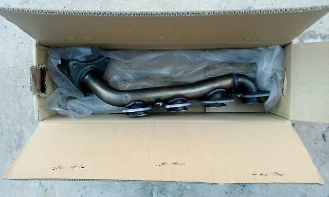
Выпускной коллектор на двигателях серии 2 uz и 3uz выполнен из стали. На двигателях серии 1 uz из чугунного сплава. С пробегом и возрастом требуется замена прокладок выпускного коллектора или коллектора целиком – появляются трещины.
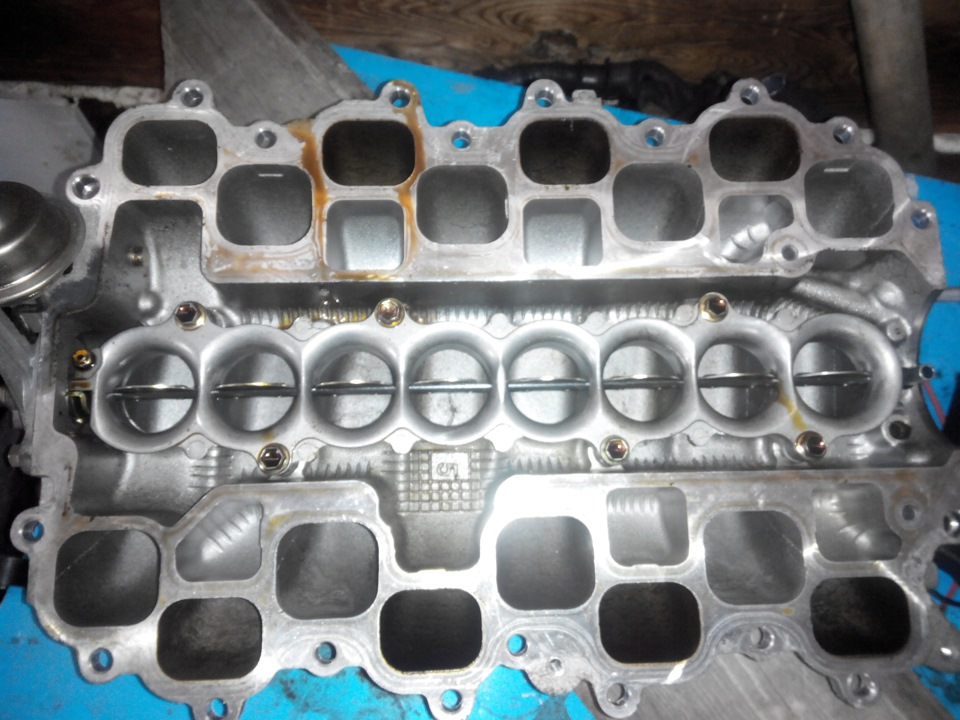
Демонтированный впускной коллектор. Обратите внимание на заслонки, расположенные по средине коллектора.
Все двигатели серии uz оснащены системой изменения геометрии впускного коллектора (ACIS)
Разберем детально принцип работы данной системы
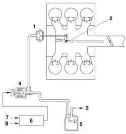
1 – исполнительный механизм; 2 – управляющий клапан системы изменения фаз газораспределения; 3 – к сглаживающему ресиверу; 4 – вакуумный клапан; 5 – вакуумный резервуар; 6 – электронный блок управления двигателя.
Принцип работы системы ACIS заключается в том, что блок управления двигателя, получая информацию с различных датчиков двигателя (датчик положения дроссельной заслонки, тахометра и т.д.) и в зависимости от конкретных условий работы закрывает или наоборот открывает заслонку, разделяющую впускной коллектор на две части. Вследствие чего увеличивается или уменьшается рабочая длинна впускного коллектора.
Выпускной коллектор требует от владельца автомобиля повышенного внимания. С пробегом существует вероятность самопроизвольного откручивания заслонок коллектора и попадания крепежных винтов, а так же самих заслонок в клапанный механизм и цилиндры двигателя. Попадания постороннего предмета в камеру сгорания двигателя в большинстве случаев потребует его замены или дорогостоящего ремонта
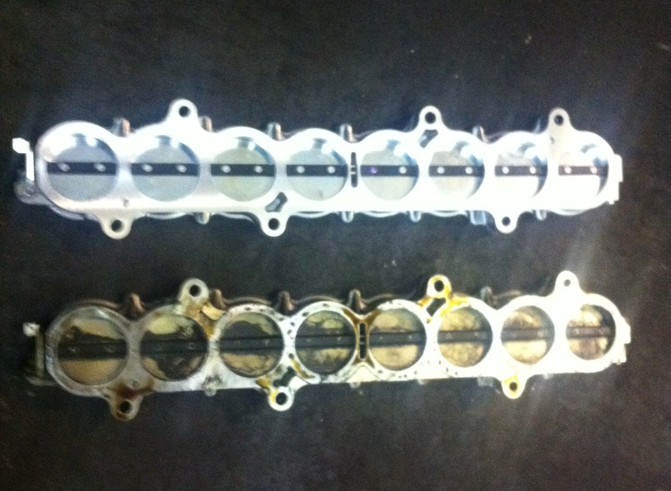
Заслонки воздушного коллектора
Разберем на примере одного из автомобилей, который пострадал от этой неисправности в декабре 2017г.
Lexus LS430 3 uz fe. Неисправность – попадание заслонки 7 цилиндра в клапанный механизм. К сожалению, повреждения оказались приговором для двигателя.
Заслонка впускного коллектора открутилась, попала в клапанный механизм, клапан остался в открытом положении, по нему ударил поршень, клапан сломало на несколько частей. Детали клапанного механизма попали в камеру сгорания. В итоге были повреждены – ГБЦ, поршень и гильза блока цилиндров.
Демонтаж впускного коллектора с двигателя 3uz fe
Отсутствуют некоторые винты крепления заслонок, а так же заслонка 7 цилиндра
Поломанный клапанный механизм
Поломанные стержни клапанов, извлеченные из камеры сгорания двигателя.
Поэтому, для предотвращения таких последствий раз в 150 000 – 200 000 крайне желательно проводить осмотр заслонок воздушного коллектора. При проведении подобных работ можно провести работы по профилактическому обслуживанию стартера ДВС, который находится в развале блока цилиндров.
EM–107
2UZ-FE ENGINE MECHANICAL – ENGINE UNIT
DISASSEMBLY
HINT:
• Thoroughly clean all parts to be assembled.
• Before installing the parts, apply new engine oil to all sliding and rotating surfaces.
• Replace all gaskets, O-rings and oil seals with new ones.
1.
REMOVE ENGINE HANGERS
(a) Remove the 4 bolts and engine hangers.
2.
REMOVE CYLINDER BLOCK WATER DRAIN COCK
SUB-ASSEMBLY
(a) Remove the 2 water drain cocks.
3.
REMOVE SPARK PLUG
4.
REMOVE OIL FILLER CAP SUB-ASSEMBLY
A072687
5.
REMOVE OIL FILLER CAP HOUSING
(a) Remove the 2 nuts and oil filler cap housing.
EM
A072688
6.
REMOVE CYLINDER HEAD COVER SUB-ASSEMBLY
(a) Remove the 9 bolts, 9 seal washers, cylinder head cover and gasket.
A072689
7.
REMOVE CYLINDER HEAD COVER SUB-ASSEMBLY
LH
(a) Remove the 9 bolts, 9 seal washers, cylinder head cover and gasket.
A072690
EM
EM–108
SST
2UZ-FE ENGINE MECHANICAL – ENGINE UNIT
8.
REMOVE NO. 2 IDLER PULLEY SUB-ASSEMBLY
(a) Remove the pulley bolt, cover plate and idler pulley.
A072691
9.
REMOVE NO. 2 TIMING BELT COVER SUB-
ASSEMBLY
(a) Remove the 2 bolts and timing belt cover.
A054467
10. REMOVE V-RIBBED BELT TENSIONER ASSEMBLY
(a) Remove the bolt, 2 nuts and belt tensioner.
A072692
11. REMOVE FAN BRACKET SUB-ASSEMBLY
(a) Remove the 2 bolts, 2 nuts and fan bracket.
A134365
12. REMOVE CRANKSHAFT DAMPER SUB-ASSEMBLY
(a) Using SST, remove the pulley bolt.
SST 09213-70011 (90105-08076), 09330-00021
A054468E03
SST
2UZ-FE ENGINE MECHANICAL – ENGINE UNIT
EM–109
(b) Using SST, remove the crankshaft pulley.
SST 09950-50013 (09951-05010, 09952-05010,
09953-05010, 09953-05020, 09954-05021)
A054470E02
13. REMOVE NO. 1 TIMING BELT COVER
(a) Remove the 4 bolts and timing belt cover.
A072694
14. REMOVE TIMING GEAR COVER SPACER
(a) Remove the cover spacer and gasket.
EM
A072695E01
15. REMOVE NO. 1 CRANKSHAFT POSITION SENSOR
PLATE
(a) Remove No. 1 crankshaft position sensor plate.
A072696E01
A054457
16. SET NO. 1 CYLINDER TO TDC / COMPRESSION
(a) If reusing the timing belt, check the installation marks on the timing belt.
(1) Check that there are 3 installation marks on the timing belt by turning the crankshaft as shown in the illustration.
If the installation marks have disappeared, put a new installation mark on the timing belt before removing each part.
EM–110
2UZ-FE ENGINE MECHANICAL – ENGINE UNIT
(b) Using the crankshaft damper bolt, turn the crankshaft to align the timing marks of the crankshaft timing pulley and oil pump body.
EM
Approx. 45°
Timing Mark
Turn
A054456E01
(c) Check that the timing marks of the camshaft timing pulleys and timing belt plates are aligned.
If not, turn the crankshaft 1 complete revolution
(360
°).
A054008
Turn
A054461E05
17. REMOVE TIMING BELT
(a) Set the No. 1 cylinder to approx. 45
° BTDC/ compression.
(1) Using the crankshaft damper bolt, turn the crankshaft counterclockwise by approx. 45
°.
NOTICE:
If the timing belt is disengaged, having the crankshaft pulley at a wrong angle can cause the piston head and valve head to come into contact with each other when removing the camshaft timing pulley and camshaft, causing damage. So always set the crankshaft pulley at the correct angle.
(b) Alternately loosen the 2 bolts, then remove the bolts, chain tensioner and dust boot.
A072697
Slightly
Turn
RH Bank:
SST
2UZ-FE ENGINE MECHANICAL – ENGINE UNIT
EM–111
(c) Using SST, loosen the tension between the camshaft timing pulley (RH bank) and crankshaft timing pulley by slightly turning the camshaft timing pulley (RH bank) counterclockwise.
SST 09960-10010 (09962-01000, 09963-00350)
(d) Disconnect the timing belt from the No. 1 timing belt idler and remove the timing belt.
A054459E02
18. REMOVE CAMSHAFT TIMING PULLEYS
(a) Hold the crankshaft with a wrench, and remove the
8 bolts and 2 timing pulleys.
EM
LH Bank:
A134373E01
19. REMOVE NO. 1 TIMING BELT IDLER SUB-
ASSEMBLY
(a) Using a 10 mm hexagon wrench, remove the bolt, idler and plate washer.
A072698
20. REMOVE NO. 2 TIMING BELT IDLER SUB-
ASSEMBLY
(a) Remove the bolt and idler.
A072699
EM
EM–112
SST
2UZ-FE ENGINE MECHANICAL – ENGINE UNIT
A072700E01
Service Bolt
A054149E01
21. REMOVE CRANKSHAFT TIMING PULLEY
(a) Using SST, remove the timing pulley.
SST 09950-50013 (09951-05010, 09952-05010,
09953-05010, 09953-05020, 09954-05010)
NOTICE:
Do not turn the timing pulley.
22. REMOVE NO. 2 REAR TIMING BELT PLATE RH
(a) Remove the 2 bolts and No. 2 rear timing belt plate
RH.
23. REMOVE REAR TIMING BELT PLATE RH
(a) Remove the bolt, stud bolt and rear timing belt plate
RH.
24. REMOVE NO. 2 REAR TIMING BELT PLATE LH
(a) Remove the 2 bolts and No. 2 rear timing belt plate
LH.
25. REMOVE REAR TIMING BELT PLATE LH
(a) Remove the bolt and rear timing belt plate LH.
26. REMOVE CAMSHAFTS
NOTICE:
Since the thrust clearance of the camshaft is small, the camshaft must be kept level while it is being removed. If the camshaft is not kept level, the portion of the cylinder head which receives the shaft thrust may crack or be damaged, causing the camshaft to seize or break. To avoid this, the following steps should be carried out.
(a) Remove the camshafts of the RH bank.
(1) In order to install a service bolt to the sub and main gears, turn the camshaft with a wrench.
The hexagonal portion of the camshaft is used for turning the camshaft with the wrench.
(2) Secure the sub-gear to the main gear with a service bolt.
Recommended service bolt:
Thread diameter 6 mm
Thread pitch
Bolt length
1.0 mm
16 to 20 mm (0.63 to 0.79 in.)
HINT:
When removing the camshafts, make sure that the torsional spring force of the sub-gear has been eliminated by the above operation.
2UZ-FE ENGINE MECHANICAL – ENGINE UNIT
EM–113
(3) Set the timing mark (1-dot mark) of the camshaft main gear at approx. 10
° angle by turning the hexagonal portion of the exhaust camshaft with a wrench.
A054150
13
14
8
7
15
16
10
17
18
9
12
11
5
6
4
3
2
21
22
20
19
1
A054151E01
Service Bolt
Align
A054152E01
(4) Uniformly loosen the 22 bearing cap bolts in the order shown in the illustration, then remove all the bolts.
(5) Remove the oil feed pipe, 9 bearing caps, oil control valve filter, camshaft housing plug and 2 camshafts.
EM
(b) Remove the camshafts on the LH bank.
(1) In order to install a service bolt to the sub and main gears, turn the camshaft with a wrench.
The hexagonal portion of the camshaft is used for turning the camshaft with the wrench.
(2) Secure the sub-gear to the main gear with a service bolt.
Recommended service bolt:
Thread diameter 6 mm
Thread pitch
Bolt length
1.0 mm
16 to 20 mm (0.63 to 0.79 in.)
HINT:
When removing the camshaft, make sure that the torsional spring force of the sub-gear has eliminated by the above operation.
(3) Align the timing marks (2-dot marks) of the camshaft drive and driven gears by turning the hexagonal portion of the exhaust camshaft with a wrench.
A054153E02
EM
EM–114
21
22
20
19
1
RH Cylinder Head:
1 7
A
9
4
2
2UZ-FE ENGINE MECHANICAL – ENGINE UNIT
3
4
6
5
11
18
12
17
9
15
13
16
10
8
14
7
A054154E01
(4) Uniformly loosen the 22 bearing cap bolts in the order shown in the illustration, then remove all the bolts.
(5) Remove the oil feed pipe, 9 bearing caps, oil control valve filter, camshaft housing plug and 2 camshafts.
HINT:
Arrange the bearing caps in the correct order.
27. REMOVE SEMICIRCULAR PLUG
3
5
LH Cylinder Head:
10
2
8
10
6 9
6
8
5
7
4
2
Front
3
A
1
A072703E01
28. REMOVE CYLINDER HEAD SUB-ASSEMBLY
(a) Uniformly loosen the 10 cylinder head bolts on one side of each cylinder head in several steps, in the order shown in the illustration. Likewise, loosen the
10 bolts on the other side. Remove the 20 cylinder head bolts and plate washers.
NOTICE:
• Cylinder head warpage or cracking may result from removing bolts in incorrect order.
• Do not drop the plate washer for cylinder head bolt into portion A of the cylinder head.
If dropped into portion A, the plate washer will pass through the cylinder head and cylinder block into the oil pan.
A002871
(b) Lift the cylinder head from the dowels on the cylinder block, and place the 2 cylinder heads on wooden blocks on a bench.
NOTICE:
• Be careful not to damage the contact surfaces of the cylinder head and cylinder block.
• The cylinder head should not be tilted so as to secure the valve lifter. If the cylinder head is tilted, remove the valve lifter and check that the adjusting shim is set correctly.
HINT:
If the cylinder head cannot be lifted easily, pry between the cylinder head and cylinder block with a screwdriver.
2UZ-FE ENGINE MECHANICAL – ENGINE UNIT
EM–115
29. REMOVE WATER PUMP ASSEMBLY
(a) Remove the 5 bolts, 2 stud bolts, nut, water pump and gasket.
SST
A134374
A072704E01
30. REMOVE NO. 2 OIL PAN SUB-ASSEMBLY
(a) Remove the 17 bolts and 2 nuts.
(b) Insert the blade of SST between the oil pan and No.
2 oil pan, and cut off applied sealer. Remove the No.
2 oil pan.
SST 09032-00100
NOTICE:
• Be careful not to damage the contact surface of the oil pan and the No. 2 oil pan.
• Be careful not to damage the No. 2 oil pan flange.
31. REMOVE OIL PAN BAFFLE PLATE
(a) Remove the 2 bolts, 2 nuts and baffle plate.
EM
A072705
32. REMOVE OIL PAN SUB-ASSEMBLY
(a) Remove the 18 bolts and 2 nuts.
A072706
EM–116
Pry
2UZ-FE ENGINE MECHANICAL – ENGINE UNIT
(b) Using a screwdriver, remove the oil pan by prying between the oil pan and cylinder block in the order shown in the illustration.
NOTICE:
• Be careful not to damage the contact surfaces of the cylinder block or oil pan.
EM
6 mm
Hexagon
Wrench
A072707E01
33. REMOVE OIL STRAINER SUB-ASSEMBLY
(a) Remove the 2 bolts, 2 nuts, oil strainer and gasket.
A072708
34. REMOVE OIL PUMP ASSEMBLY
(a) Remove the 7 bolts and stud bolt.
HINT:
Use a 6 mm hexagon wrench to tighten the hexagon head bolt.
B013038E03
(b) Using a screwdriver, remove the oil pump by prying the portions between the oil pump and cylinder block.
NOTICE:
Be careful not to damage the contact surfaces of the cylinder block and oil pump.
(c) Remove the O-ring from the cylinder block.
B002617
Pry
Claw
Bend
Do not remove
10 mm
Hexagon
Wrench
2UZ-FE ENGINE MECHANICAL – ENGINE UNIT
EM–117
35. REMOVE ENGINE REAR OIL SEAL RETAINER
(a) Remove the 7 bolts.
(b) Using a screwdriver, remove the oil seal retainer by prying the portions between the oil seal retainer and crankshaft bearing cap.
(c) Remove the O-ring.
Pry
A005086E01
36. REMOVE SPARK PLUG TUBE GASKET
(a) Bend the 4 ventilation case claws installed on the cylinder head cover to an angle of 90
° or more.
(b) Using a screwdriver, pry out the gasket.
NOTICE:
Be careful not to damage the cylinder head cover. Tape the screwdriver tip.
A004107E01
A054961E02
37. REMOVE CAMSHAFT TIMING TUBE ASSEMBLY
(a) Mount the hexagonal portion of the camshaft in a vise.
NOTICE:
• Be careful not to damage the camshaft.
• Do not remove the 4 bolts shown in the illustration. If any of them are loosened or removed, the backlash of the gear in the timing tube will go out of adjustment. In this case, replace the timing tube assembly with a new one.
(b) Remove the screw plug and seal washer.
(c) Using a 10 mm hexagon wrench, and remove the bolt.
(d) Pull out the timing tube and drive gear assembly from the camshaft.
EM
5 mm Hexagon
Wrench
SST
A054962E02
(e) Using SST and a 5 mm hexagon wrench, remove the 4 bolts, drive gear and oil seal.
SST 09960-10010 (09962-01000, 09963-00500)
NOTICE:
Be careful not to damage the timing tube.
A054965E03
EM–118
2UZ-FE ENGINE MECHANICAL – ENGINE UNIT
38. REMOVE CAMSHAFT SUB GEAR
(a) Mount the hexagonal portion of the camshaft in a vise.
NOTICE:
Be careful not to damage the camshaft.
EM
Service Bolt
A054968
SST
Turn
A054969E01
(b) Using SST, turn the sub gear clockwise, and remove the service bolt.
SST 09960-10010 (09962-01000, 09963-00500)
Recommended service bolt:
Thread diameter 6 mm
Thread pitch
Bolt length
1.0 mm
16 to 20 mm (0.63 to 0.79 in.)
(c) Using snap ring pliers, remove the snap ring.
(d) Remove the wave washer, sub gear and gear spring.
HINT:
Arrange the camshaft sub gears and gear spring
(RH and LH sides).
A054970
39. REMOVE OIL PUMP SEAL
(a) Using a screwdriver, pry out the oil seal.
NOTICE:
Be careful not to damage the oil pump body.
Tape the screwdriver tip.
A054145E01
A054147
40. REMOVE ENGINE REAR OIL SEAL
(a) Using a screwdriver and hammer, tap out the oil seal.
41. REMOVE VALVE LIFTER
(a) Remove the valve lifter and adjusting shim.
HINT:
Arrange the valve lifters and shims in the correct order.
SST
SST
2UZ-FE ENGINE MECHANICAL – ENGINE UNIT
EM–119
42. REMOVE INTAKE VALVE
(a) Using SST, compress the valve spring and remove the 2 valve spring retainer locks.
SST 09202-70020 (09202-01010)
(b) Remove the spring retainer, valve spring, valve and spring seat.
HINT:
Arrange the valves, valve springs, spring seats and spring retainers in the correct order.
A050250E02
43. REMOVE EXHAUST VALVE
(a) Using SST, compress the valve spring and remove the 2 valve spring retainer locks.
SST 09202-70020 (09202-00010)
(b) Remove the spring retainer, valve spring, valve and spring seat.
HINT:
Arrange the valves, valve springs, spring seats and spring retainers in the correct order.
EM
A050249E02
44. REMOVE VALVE STEM OIL SEAL
(a) Using needle-nose pliers, remove the oil seal.
A003192
A005100
45. INSPECT CONNECTING ROD THRUST CLEARANCE
(a) Using a dial indicator, measure the thrust clearance while moving the connecting rod back and forth.
Standard thrust clearance:
0.160 to 0.290 mm (0.0063 to 0.0114 in.)
Maximum thrust clearance:
0.35 mm (0.0138 in.)
If the thrust clearance is greater than the maximum, replace the connecting rod assembly. If necessary, replace the crankshaft.
Connecting rod thickness (Reference):
22.880 to 22.920 mm (0.9008 to 0.9024 in.)
EM–120
EM
Plastigage
2UZ-FE ENGINE MECHANICAL – ENGINE UNIT
46. INSPECT CONNECTING ROD OIL CLEARANCE
(a) Check the matchmarks on the connecting rod and cap to ensure correct reassembly.
(b) Remove the 2 connecting rod cap bolts.
A005104
A005105
(c) Using the removed connecting rod cap bolts, remove the connecting rod cap and lower bearing by wiggling the connecting rod cap right and left.
HINT:
Keep the lower bearing inserted with the connecting rod cap.
(d) Clean the crank pin and bearing.
(e) Check the crank pin and bearing for pitting and scratches.
If the crank pin or bearing is damaged, replace the bearings. If necessary, replace the crankshaft.
(f) Lay a strip of Plastigage across the crank pin.
A005102E01
(g) Match the numbered connecting rod cap with the connecting rod.
(h) Align the pin groove of the connecting rod cap with the pins of the connecting rod, and install the connecting rod cap.
A005106
LH Bank:
Front
2UZ-FE ENGINE MECHANICAL – ENGINE UNIT
EM–121
(i) Check that the outside mark of the connecting rod cap is facing in the correct direction.
HINT:
• The connecting rod cap bolts are tightened in 2 progressive steps.
• If any one of the connecting rod cap bolts is broken or deformed, replace it.
RH Bank:
Front
Outside Mark (Protrusion)
Outside Mark (Protrusion)
A005174E02
90°
Front
Painted
Mark
90°
A005101
(j) Apply a light coat of engine oil to the threads and under the heads of the connecting rod cap bolts.
(k) Install and alternately tighten the 2 connecting rod cap bolts in several steps.
Torque: 25 N*m (250 kgf*cm, 18 ft.*lbf)
NOTICE:
Do not turn the crankshaft.
If any one of the connecting rod cap bolts does not meet the torque specification, replace the connecting rod cap bolts.
(l) Mark the front of the connecting cap bolts with paint.
(m) Retighten the cap bolts 90
° as shown in the illustration.
(n) Check that the painted mark is now at a 90
° angle to the front.
EM
A005099E02
(o) Remove the 2 bolts, connecting rod cap and lower bearing.
A005101
EM
EM–122
Number Mark
No. 1
No. 2
No. 4
No. 3
Number Mark
2UZ-FE ENGINE MECHANICAL – ENGINE UNIT
Number Mark
A139502E01
Ridge Reamer
A054348E02
(p) Measure the Plastigage at its widest point.
Standard oil clearance:
0.021 to 0.047 mm (0.0008 to 0.0019 in.)
Maximum oil clearance:
0.065 mm (0.0026 in.)
If the oil clearance is greater than the maximum, replace the bearings. If necessary, replace the crankshaft.
HINT:
If using a standard bearing, replace it with one having the same number. If the number of the bearing cannot be determined, add together the numbers imprinted on the connecting rod cap and crankshaft, then select the bearing with the same number as the total. There are 6 sizes of standard bearings, marked «2», «3», «4», «5», «6» and «7».
Item Number Mark
Connecting rod cap 1 1 2 1 2 3 2 3 4 3 4 4
Crankshaft
Use bearing
1
2
2
3
1 3 2
4
1 3 2
5
1 3
6
2 3
7
EXAMPLE:
Connecting rod cap «3» + Crankshaft «1» = Total number 4 (Use bearing «4»)
Connecting rod big end inside diameter:
Mark «1» 55.000 to 55.006 mm (2.1654 to 2.1656 in.)
Mark «2»
Mark «3»
Mark «4»
55.006 to 55.012 mm (2.1656 to 2.1658 in.)
55.012 to 55.018 mm (2.1658 to 2.1661 in.)
55.018 to 55.024 mm (2.1661 to 2.1663 in.)
Crankshaft crank pin diameter:
Mark «1» 51.994 to 52.000 mm (2.0470 to 2.0472 in.)
Mark «2»
Mark «3»
51.988 to 51.994 mm (2.0468 to 2.0470 in.)
51.982 to 51.988 mm (2.0465 to 2.0468 in.)
Standard sized bearing center wall thickness:
Mark «2» 1.487 to 1.490 mm (0.0585 to 0.0587 in.)
Mark «3»
Mark «4»
Mark «5»
Mark «6»
Mark «7»
1.490 to 1.493 mm (0.0587 to 0.0588 in.)
1.493 to 1.496 mm (0.0588 to 0.0589 in.)
1.496 to 1.499 mm (0.0589 to 0.0590 in.)
1.499 to 1.502 mm (0.0590 to 0.0591 in.)
1.502 to 1.505 mm (0.0591 to 0.0593 in.)
(q) Completely remove the Plastigage.
47. REMOVE PISTON AND CONNECTING ROD
(a) Using a ridge reamer, remove all the carbon from the top of the cylinder.
(b) Push the piston, connecting rod assembly and upper bearing through the top of the cylinder block.
HINT:
• Keep the bearings, connecting rod and cap together.
• Arrange the piston and connecting rod assemblies in the correct order.
2UZ-FE ENGINE MECHANICAL – ENGINE UNIT
EM–123
48. REMOVE PISTON
(a) Check the fitting condition between the piston and piston pin.
(1) Try to move the piston back and forth on the piston pin.
If any movement is felt, replace the piston and pin as a set.
A004862
(b) Using a piston ring expander, remove the 2 piston rings.
(c) Remove the oil ring (2 side rails and expander) by hand.
HINT:
Arrange the piston rings in the correct order.
EM
A004873
(d) Using a screwdriver, pry out the 2 snap rings.
A004860
(e) Gradually heat the piston to approx. 60
°C (140°F).
A004887
(f) Using a plastic hammer and brass bar, lightly tap out the piston pin and remove the connecting rod.
HINT:
• The piston and pin are a matched set.
• Arrange the pistons, pins, rings, connecting rods and bearings in the correct order.
A004888
EM
EM–124
1
5
2
9
6
7
3
2UZ-FE ENGINE MECHANICAL – ENGINE UNIT
A005096
49. INSPECT CRANKSHAFT THRUST CLEARANCE
(a) Using a dial indicator, measure the thrust clearance while prying the crankshaft back and forth with a screwdriver.
Standard thrust clearance:
0.020 to 0.220 mm (0.0008 to 0.0087 in.)
Maximum thrust clearance:
0.30 mm (0.0118 in.)
If the thrust clearance is greater than the maximum, replace the thrust washers as a set.
Thrust washer thickness
STD 2.440 to 2.490 mm (0.0961 to 0.0980 in.)
O/S 0.125
2.503 to 2.553 mm (0.0985 to 0.1005 in.)
50. INSPECT CRANKSHAFT OIL CLEARANCE
(a) Uniformly loosen and remove the 10 crankshaft bearing cap bolts in several steps, in the order shown in the illustration.
4
8
10
A005095E01
A005093
(b) Using 2 screwdrivers, pry out the crankshaft bearing cap, and remove the 5 crankshaft bearing caps, 5 lower bearings and 2 lower thrust washers (No. 3 crankshaft bearing cap only).
NOTICE:
Be careful not to damage the cylinder block.
HINT:
• Keep the lower bearing and crankshaft bearing cap together.
• Arrange the crankshaft bearing caps and lower thrust washers in the correct order.
(c) Lift out the crankshaft.
(d) Remove the 2 upper thrust washers.
HINT:
• Arrange the upper thrust washers in the correct order.
• Keep the upper bearings together with the cylinder block.
(e) Clean each crankshaft journal and bearing.
(f) Check each crankshaft journal and bearing for pitting and scratches.
If the journal or bearing is damaged, replace the bearings. If necessary, replace the crankshaft.
Plastigage
2UZ-FE ENGINE MECHANICAL – ENGINE UNIT
EM–125
(g) Place the crankshaft on the cylinder block.
(h) Lay a strip of Plastigage across each journal.
A005097E01
A005091
10
6
9
2
5
4
8
1
3
7
A005095E02
90°
Front
Painted
Mark
90°
(i) Install the 5 crankshaft bearing caps in their proper locations.
HINT:
• The crankshaft bearing cap bolts are tightened in
2 progressive steps (Procedures «A» and «B»).
• If any one of the main bearing cap bolts is broken or deformed, replace it.
EM
(j) Apply a light coat of engine oil to the threads and under the heads of the crankshaft bearing cap bolts.
(k) Install and uniformly tighten the 10 crankshaft bearing cap bolts in several steps, in the order shown in the illustration (Procedure «A»).
Torque: 27 N*m (275 kgf*cm, 20 ft.*lbf)
NOTICE:
Do not turn the crankshaft.
If any one of the crankshaft bearing cap bolts does not meet the torque specification, replace the crankshaft bearing cap bolt.
(l) Mark the front of the crankshaft bearing cap bolts with paint.
(m) Retighten the crankshaft bearing cap bolts by 90
° in the order shown (Procedure «B»).
(n) Check that the painted mark is now at a 90
° angle to the front.
(o) Remove the crankshaft bearing caps.
A005094E02
EM
EM–126
No. 3 No. 4
2UZ-FE ENGINE MECHANICAL – ENGINE UNIT
No. 5
Number Mark
No. 2
No. 1
Number Mark
No. 2
No. 1
No. 5
No. 3
No. 4
Number Mark
A139503E01
(p) Measure the Plastigage at its widest point.
Standard clearance
No. 1 and No. 5
0.028 to 0.046 mm
(0.0011 to 0.0018 in.)
Others
0.040 to 0.058 mm
(0.0016 to 0.0023 in.)
Maximum clearance
No. 1 and No. 5
0.065 mm (0.0026 in.)
Others
0.065 mm (0.0026 in.)
If the oil clearance is greater than the maximum, replace the bearings. If necessary, replace the crankshaft.
HINT:
If using a standard bearing, replace it with one having the same number. If the number of the bearing cannot be determined, add together the numbers imprinted on the cylinder block and crankshaft, then refer to the table below for the appropriate bearing number. There are 5 sizes of the standard bearings. For No. 1 and No. 5 position bearings, use bearings marked «3», «4», «5», «6» and
«7». For the other position bearings, use bearings marked «1», «2», «3», «4» and «5».
No. 1 and No. 5:
Use bearing
Cylinder block (A)
+
Crankshaft (B)
0 to 5
6 to 11
12 to 17
18 to 23
24 to 28
5
6
3
4
7
EXAMPLE:
Cylinder block «08» + Crankshaft «06» = Total number 14 (Use bearing «5»)
Others:
Use bearing
Cylinder block (A)
+
Crankshaft (B)
0 to 5
6 to 11
12 to 17
18 to 23
24 to 28
3
4
1
2
5
EXAMPLE:
Cylinder block «08» + Crankshaft «06» = Total number 14 (Use bearing «3»)
Cylinder block crankshaft journal bore diameter (A):
Mark «00» 72.000 mm (2.8347 in.)
Mark «01»
Mark «02»
Mark «03»
Mark «04»
Mark «05»
Mark «06»
72.001 mm (2.8347 in.)
72.002 mm (2.8347 in.)
72.003 mm (2.8348 in.)
72.004 mm (2.8348 in.)
72.005 mm (2.8348 in.)
72.006 mm (2.8349 in.)
EM–127
2UZ-FE ENGINE MECHANICAL – ENGINE UNIT
Mark «07»
Mark «08»
Mark «09»
Mark «10»
Mark «11»
Mark «12»
Mark «13»
Mark «14»
Mark «15»
Mark «16»
72.007 mm (2.8349 in.)
72.008 mm (2.8350 in.)
72.009 mm (2.8350 in.)
72.010 mm (2.8350 in.)
72.011 mm (2.8351 in.)
72.012 mm (2.8351 in.)
72.013 mm (2.8352 in.)
72.014 mm (2.8352 in.)
72.015 mm (2.8352 in.)
72.016 mm (2.8353 in.)
Crankshaft journal diameter (B):
Mark «00» 67.000 mm (2.6378 in.)
Mark «01»
Mark «02»
Mark «03»
Mark «04»
Mark «05»
Mark «06»
Mark «07»
Mark «08»
Mark «09»
Mark «10»
Mark «11»
Mark «12»
66.999 mm (2.6378 in.)
66.998 mm (2.6377 in.)
66.997 mm (2.6377 in.)
66.996 mm (2.6376 in.)
66.995 mm (2.6376 in.)
66.994 mm (2.6376 in.)
66.993 mm (2.6375 in.)
66.992 mm (2.6375 in.)
66.991 mm (2.6374 in.)
66.990 mm (2.6374 in.)
66.989 mm (2.6374 in.)
66.988 mm (2.6373 in.)
Standard bearing center wall thickness No. 1 and
No. 5:
Mark «3» 2.487 to 2.490 mm (0.0979 to 0.0980 in.)
Mark «4»
Mark «5»
Mark «6»
Mark «7»
2.490 to 2.493 mm (0.0980 to 0.0982 in.)
2.493 to 2.496 mm (0.0982 to 0.0983 in.)
2.496 to 2.499 mm (0.0983 to 0.0984 in.)
2.499 to 2.502 mm (0.0984 to 0.0985 in.)
Others:
Mark «1»
Mark «2»
Mark «3»
Mark «4»
Mark «5»
2.481 to 2.484 mm (0.0977 to 0.0978 in.)
2.484 to 2.487 mm (0.0978 to 0.0979 in.)
2.487 to 2.490 mm (0.0979 to 0.0980 in.)
2.490 to 2.493 mm (0.0980 to 0.0982 in.)
2.493 to 2.496 mm (0.0982 to 0.0983 in.)
(q) Completely remove the Plastigage.
51. REMOVE CRANKSHAFT
(a) Lift up the crankshaft.
(b) Remove the 5 upper crankshaft bearings and 2 upper thrust washers from the cylinder block.
HINT:
Arrange the crankshaft bearing caps, bearings and thrust washers in the correct order.
52. REMOVE CRANKSHAFT PULLEY SET
CRANKSHAFT KEY
EM
2UZ-FE — 4.7-литровый мотор компании Toyota, выпускаемый в период 1998-2012 гг. Устанавливался на мощные пикапы и внедорожники компании. Мощность от 230 до 282 лошадиных сил и две версии: с системой VVT-i или без нее.
Технические особенности двигателя 2UZ-FE
Мотор 2UZ-FE находится на первом месте по объему в линейке «UZ». Выпуском занимались заводы, находящиеся в Аичи, Тахаре, Японии и Соединенных Штатах. Двигатель производился в 2-х версиях: с механизмом изменения фаз газораспределения VVTi и без нее. В обоих случаях мотор имеет чугунный блок цилиндров и алюминиевую головку.
Для получения подробной информации можно найти номер двигателя, который нанесен в развале блока и в передней части. Имеющиеся цифры можно использовать для расшифровки и получения точных параметров.
Характеристики мотора
Параметры ДВС:
- число цилиндров и клапанов — 8 и 32 соответственно;
- диаметр цилиндра и ход поршня — 94 и 84 мм соответственно;
- мощность — от 230 до 282 лошадиных сил;
- крутящий момент — 410-440 Н*м;
- ресурс — до 500 тыс. км;
- степень сжатия — 10 к 1;
- расположение цилиндров — V-образное;
- класс экологичности — Евро 3 и 4;
- вес — от 230 до 255 кг.

Перечень модификаций ДВС
История серии «UZ» началась в 1989 году. Первым появился 1UZ-FE, предназначенный для установки на спортивные и дорогие машины. В 1998-м выпустили 2UZ-FE с VVT-i или без нее. Последним был 4.3-литровый силовой агрегат 3UZ-FE. Он изготавливался на заводах в Японии, оснащался системой впрыска SPFI и DOHC-системой.
Считается, что для всех моторов при правильном тюнинге доступно увеличение мощности до 1000 HP. Это не так, ведь на практике удается добиться параметра вдвое меньше (подробнее об этом в отдельном разделе).


Расход топлива
Рекомендуемый производителем тип топлива — АИ-95. Заливать горючее в меньшем качестве не рекомендуется из-за риска повреждения.
Расход бензина в условиях города достигает 16.5 л, по трассе — 10 л, а в смешанном цикле — 12.5 л. Для такого объема это классический показатель.

На какие автомобили ставили двигатель 2UZ-FE
За время выпуска мотор 2UZ-FE ставился на многие машины, среди которых Mitsubishi, Nissan, Land Cruiser 200, Nissan Avenir, Lexus GX и другие. Для наглядности сведем данные в таблицу.
| Марка | Модель | Годы выпуска |
| Тойота | Land Cruiser 100 | 1998-2007 |
| Tundra 1 | 2000-2006 | |
| Land Cruiser 200 | 2007-2011 | |
| Tundra 2 | 2006-2009 | |
| Sequoia 2 | 2007-2009 | |
| Sequoia XK40 | 2001-2007 | |
| 4Runner 4 | 2003-2009 | |
| Лексус | GX470 1 | 2002-2009 |
| LX470 2 | 1998-2007 |


Варианты тюнинга мотора
Цилиндры мотора расположены по V-образной схеме, что в комплексе с надежностью силовой части дает возможность оптимизировать устройство. Для этого доступны следующие методы:
- Установка компрессора Кит от TRD. Можно купить новый или поставить бывший в эксплуатации вариант. Дополнительно рекомендуется докупить выхлоп-прямоток и коллекторы 4-2-1. При правильном подходе удается увеличить мощность до 350 лошадиных сил. Для улучшения результата рекомендуется поставить поршни из кованого металла, ARP-шпильки, шатуны, улучшенные форсунки, ЭБУ VEMS и обеспечить подачу воздуха под давлением 0.7 бар. В таком случае мощность увеличится до 400 «лошадок».
- Турбо. В качестве замены компрессору рекомендуется использовать турбо, созданное на Turbo Kit. На выбор доступна покупка готового узла Garrett GT 40 или самостоятельный сбор. В последнем случае необходим коллектор, интеркулер и турбина. Для решения задачи также пригодится контроллер буста, блок управления VEMS, вестгейт, хомуты, устройств слива и подачи масла, теплоизоляционный материал и хомуты. Результат — увеличение мощности до 450 л. с.
- Двойное турбо. Как вариант, стоит найти и купить 2 турбины Garrett VNT25, а после поставить кованую поршневую. Мощность увеличится до 500 «лошадей».

В рассмотренных случаях подойдут нагнетатели большей мощности, но тогда придется дорабатывать двигатель и повышать давление наддува. В случае ошибки высок риск повреждения и выхода из строя силового агрегата.
Регламент обслуживания 2UZ-FE
Базовые правила техобслуживания:
- объем масла / периодичность замены — 6.8 л / до 10 000 км;
- хладагент, насос — до 150 000 км;
- свечи зажигания — через 80 000 км;
- ремень ГРМ — раз в 100 000 км;
- заслонка коллектора впуска — раз в 150-200 тыс. км;
- проверка зазоров клапанов — через 130-150 тыс. км.

Двигатель 2UZ-FE, как и другие представители линейки «UZ», отличаются неприхотливостью к обслуживанию. Достаточно проводить работы с учетом технического регламента и следить за состоянием.
При выборе масла рекомендуется отдавать предпочтение рабочим жидкостям 5W-30 по SAE и следовать рекомендациям завода-изготовителя.

Недостатки, поломки и проблемы Toyota 2UZ-FE
Несмотря на видимую надежность, 2UZ-FE имеет ряд слабых мест, которые должны знать автовладельцы. К основным проблемам стоит отнести:
Истирание и повреждение клапанов VVTi. Неисправность легко распознать по ухудшению динамики и падению оборотов.
Повреждение стального коллектора впуска. В версии 1UZ-FE он изготовлен из чугуна и имеет больший срок службы. Здесь же важно следить за состоянием и сразу реагировать на повреждения.
Риск откручивания заслонок и попадания винтов внутрь цилиндра. Результатом может стать необходимость капитального ремонта.
Ослабление крепления заслонки коллектора впуски и ее падение в клапанный узел.
Растяжение ремня ГРМ двигателя 2UZ-FE. Узел имеет небольшой ресурс, поэтому замена выполняется с периодичностью раз в 100 000 км.
Неисправность насоса. Как и ремень, он имеет небольшой срок службы и меняется с такой же периодичностью.
Выход из строя гидравлического натяжителя. Элемент, который при механическом воздействии может повредиться. С ним нужно обращаться осторожно.


К недостаткам 2UZ-FE также стоит отнести большую массу, повышенный расход топлива, периодическое регулирование клапанных зазоров.
Ремонт двигателя Toyota 2UZ-FE
При эксплуатации автомобиля с рассматриваемым мотором необходимо сделать за его состоянием и периодически проводить ремонт. Действия автовладельца зависят от типа неисправности.
Рассмотрим основные поломки и шаги по ремонту:
- Повышенный расход антифриза. Для восстановления требуется замена насоса патрубков, насоса или прокладки ГБЦ.
- Посторонние звуки в районе головки блока цилиндров. Проводится ремонт ГБЦ или регулирование зазоров клапанов.
- Уменьшение мощности и момента Н*м. При таких поломках необходим ремонт мотора, контроль и замена датчиков при неисправности.
- Сбои оборотов. Для устранения неисправности проводится чистка клапана, диагностика и ремонт системы VVT-i.
Опыт эксплуатации мотора 2UZ-FE
Двигатели линейки «UZ» хорошо себя показали в процессе эксплуатации. При правильном и своевременном обслуживании они могут отходить не меньше 500 000 км. Если этого мало, ресурс двигателя легко увеличить путем капитального ремонта.
2UZ-FE хорошо себя показывает в нижних оборотах, легко переключается на пониженную Расход топлива в городе высокий, но на трассе имеет неплохие показатели. Мощности всегда хватает, в том числе на скорости более 180 км/ч. При этом сохраняется ощущение запаса.
В комментариях расскажите об опыте эксплуатации машины с мотором 2UZ-FE. Приведите неисправности, с которыми приходилось сталкиваться, выделите плюсы ДВС. Сохраните материал в закладки, чтобы в любой момент вернуться к полезной информации.