Page 64: Disassembly And Reassembly Of Major Components
Page 77: Inspection
Page 116: Breaking-In
Page 117: Maintenance Of Major Components
Page 121: Fuel Injection Pump
Doosan DE12T Operation & Maintenance Manual
Quick Links
Summary of Contents for Doosan DE12T
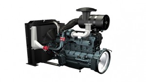
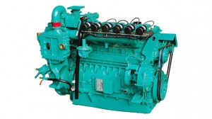
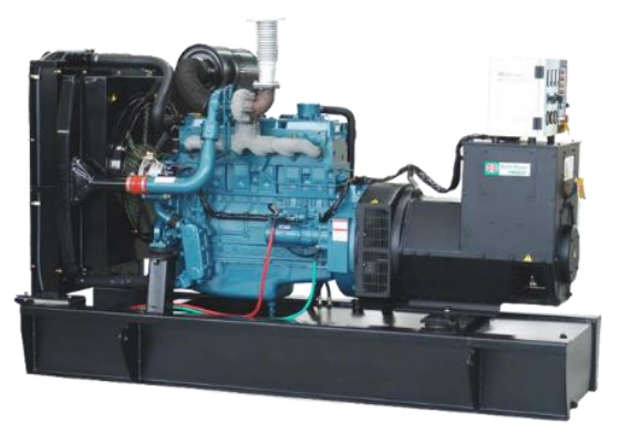
Page 2 /P126TI /P126TI-1/DE12T. The POLUS means ‘Power Plus’ that is represented more powerful Doosan generating-set engines and it is marked on engine name as an initial P. On the other hand, intial D stands for standard engine prior to POLUS version.
Page 3: Table Of Contents
Page 5: Safety Regulations
Page 7: Regulations Designed To Prevent Pollution
Page 9: General Information
Page 13: Engine Specification
Page 14: Technical Information
Page 15: Engine Type
Page 16: Engine Timing
Page 17: Lubrication System
0.855 Flash Point D 93 100 (38) 125 (52) 131 (55) û.
Page 21 3.8. Cooling System The engine has a liquid-cooling system. The fresh water pump is a maintenance-free by gear from the crankshaft. Depending on the agreed extent of delivery and the design of the engine, the coolant circuit can be equipped with temperature monitors which, in the event of loss of coolant, shut the engine down.
Page 22 For the improper control might give the fatal damage to the cooling water pump and cylinder liners, detail care is needed. ¥ Since DE12T , P126TI and P126TI- cylinder liner is dry type, particularly the cooling water control should be applied thoroughly.
Page 23 Note : In taking the cooling water sample, if the water in auxiliary tank were taken, it is hard to measure the accurate density. Take the cooling water sample necessarily loosen- ing the cooling water discharge plug. 2) At the state of a test paper soaked in the sampled water, after taking the paper out through water agitation, shake off the water.
Page 24 3.9. V-belt Tension Check and Adjust By the finger-pressure the belt is pressed by Press hear here 10mm
15mm between the fan pulley and 15mm the alternator pulley in normal condition. For Alternator the adjustment of the tension, loosen the Pulley Pulley adjusting bolts which support the alternator.
Page 25: Electrical Equipment
Page 27: Commissioning And Operation
Page 29: Operation In Winter Time
Page 30: Tuning The Engine
Page 31: Maintenance And Care
Page 34: Cooling System
Page 39: Fuel System
3 turns until draining occurs.
Page 40 5.5.3. Fuel system checks Fill the tank with the recommended fuel. Keeping tanks full reduces water condensation and helps keep fuel cool, which is important to engine performance. Make sure fuel supply valves (if used) are open. To insure prompt starting and even running, the fuel system must be primed with the fuel feed pump manually before starting the engine the first time, or after a fuel filter change.
Page 41 5.5.5. Priming pump strainer cleaning Clean the priming pump strainer every 200 operation hours. The strainer is incorporated in the priming pump inlet side joint bolt. Clean the strainer with the compressed air and rinse it in the fuel oil. Strainer(Inner) EA7O5009 5.5.6.
Page 42 ¥ Check injection pressure, and adjust the nozzle using the adjusting shim if the pressure does not meet the specified limit. ¥ Check nozzle spray patterns and replace if damaged. DE12T P126TI / P126TI- 1st : 160kg/cm Opening pressure 220kg/cm.
Page 43: Turbocharger
Page 45: Checking And Setting
Page 48: Cylinder Compression Pressure
8.5 kg . m Torque ¥ Install the oil delivery pipe and return pipe. 6.3.
Page 49 6.4. V-belts The tension of the V-belts should be checked after every 2,000 hours of operation. (1) Change the V-belts if necessary If in the case of a multiple belt drive, wear or differing tensions are found, always replace the complete set of belts.
Page 50 75 kg 70 kg 60 kg 20.2 mm 75 kg 70 kg 60 kg : Adopted in DE12T and P126TI / P126TI- (5) Tensioning and changing V-belt ¥ Remove fixing bolts. (1) ¥ Remove lock nut. (2) ¥ Adjust nut (3) until V-belts have correct tensions.
Page 51: Operation Tip
Page 59: Causes And Remedies
Page 62: General Information
Page 63: Engine Characteristics
Page 64: Disassembly And Reassembly Of Major Components
Page 77: Inspection
Tension at 37mm 61.8 kg.
Page 83 2) Rocker arm • Visual check Visually check the face of the rocker arm in contact with the valve stem end for scores and step wear. If the wear is small, correct it with an oil stone or grind- ing paper of fine grain size. Rocker arm with a considerable amount of step wear should be replaced.
Page 84 • Visual check of tappet Visually check the face of the tappets in contact with the cam for pitting, scores or cracks, and replace if severely damaged. If the amount of cracks or pitting is small, Unevenness Crack Normal correct with an oil stone or grinding ❘❏❆✔✠✟☛.
59.88 mm 59.52 mm Use a micrometer to measure the cam journal diameter. I II If the measured number is less than the I II specified limit, camshaft.
Page 86 • Run-out Support the camshaft on two V blocks and check for run-out using a dial indi- cator. Correct or replace the cam shaft if the amount of run-out is beyond the value indicating need for servicing. Standard Limit 0.05 mm 0.2 mm EA0M4066 3) Cam shaft end play.
Page 87 2) Wear With an outside micrometer measure the • diameter of the crankshaft journals and pins in the directions as shown, and compare the measured values to deter- mine the amount of wear. If the amount of wear is beyond the limit, •.
Page 88 3) Crankshaft run-out Support the crankshaft on V blocks. • Turn the crankshaft with a dial indicator • placed on the surface plate and take the amount of crankshaft run-out. Standard Limit 0.05 mm 0.1 mm 9.2.7. Crank shaft bearing and connection rod bearing 1) Visual check Visually check the crankshaft bearing and connecting rod bearing for scores, uneven.
Page 89 • Connecting rod bearing clearance Install the connecting rod bearing in the connecting rod bearing cap, tighten the connecting rod cap bolts to the specified torque, then measure the inside diame- ter. • 28 kg Torque 83.02
83.092 mm Standard Dia.
Page 90 Spread = O A — O B EDM2047I • Crankshaft bearing crush Install the bearing and cap in the cylinder block, retighten the bolts to specified torque, unscrew out one bolt completely, then measure the clearance between the bearing cap and cylinder block using a feeler gauge.
Page 91 9.2.8. Piston 1) Visual check Visually check the pistons for cracks, scuff or wear, paying particular attention to the ring groove. 2) Clearance between the piston and cylinder liner With an outside micrometer, measure • the piston outside diameter at a point 18mm away from the lower end of pis- ton skirt in a direction at a right angle to the piston pin hole.
Page 92 9.2.9. Piston rings 1) Visual check Replace the piston rings with new ones if detected worn or broken when the engine is overhauled. 2) Piston ring gap Insert the piston ring into the upper por- • tion of the cylinder liner bore so that it is held at a right angle to the cylinder liner wall.
Page 93 4) Piston ring tension With a tension tester, measure piston ring tension. Replace the piston ring if the measured value is beyond the limit. Standard Top ring 2.27
3.41 kg 2nd ring 2.0
3.0 kg Oil ring 4.03
5.57 kg 9.2.10.
Page 94 9.2.11. Connecting rod 1) Distorsion Check the connecting rod for distortion. As shown in the figure below, install the connecting rod to the connecting rod tester, and check for distortion using a feeler gauge. If the connecting rod is found distorted, never re-use it but replace with a new one.
Page 95 9.3. Reassembly 9.3.1. General precautions ¥ Wash clean all the disassembled parts, particularly oil and water ports, using compressed air, then check that they are free from restrictions. ¥ Arrange the general and special tools in order for engine assembly operation. ¥.
Page 96 ¥ Apply engine oil to the entire face of the tappets and slide them into the tappet holes on the cylinder block. ¥ Wet the cam bush inside diameter and camshaft with oil, and carefully assem- ble them while turning the camshaft. ¥.
Page 97 ¥ Semi-tighten a bolt at both sides of the crankshaft, apply engine oil to journals and pins, then assemble the crankshaft with the cylinder block by tightening the fixing bolts. ¥ Install the oiled thrust washers with the oil groove facing outward. ¥.
Page 98 ¥ Apply oil to the entire part of the bearing cap bolts, then tighten in tightening sequence to specified torque. ¥ Torque 30 kg ¥ After semi-tightening both bolts evenly, tighten them diagonally specified torque using a torque wrench as follows. EQM3059I .
Page 99 9.3.8. Flywheel ¥ Install a guide bar into a bolt hole on the crank shaft, and lift the flywheel to align the dowel pin with the pin hole on the fly- wheel for temporary assembly opera- tion. ¥ Install bolts in the remaining holes, take out the guide bar, then install a bolt in the hole where the guide bar had been inserted.
Page 100 9.3.11. Timing gear ¥ Install the oil pump idle gear onto the No.7 bearing cap. ¥ Install a thrust washer over the camshaft Idle gear pin and assemble the cam gear by aligning it with camshaft key groove. Torque 3.1 kg ¥.
Page 101 9.3.12. Timing gear case cover ¥ Install dowel pin on the timing gear case. ¥ Mount a gasket by aligning the fixing bolt holes with those on the gasket. ¥ Align the dowel pin with the cover pin hole, then install the cover with light tap. ¥.
Page 102 9.3.15. Piston and connecting rod ¥ Use a piston heater to heat the piston approximately 100 ûC (212 ûF ) for 5 min- utes. ¥ Align the piston pin hole with the oiled connecting rod small end and press the piston pin (by lightly tapping with a rub- ber hammer) to assemble the connect- ing rod with the piston.
Page 103 ¥ Identify the mark «Y» or «TOP» on the ring end to prevent the top and bottom of the piston ring is interchanged each other and make the marked top face upward. Note : Be sure to make the piston ring end marked face(«Y».
Page 104 ¥ Wet the fixing bolts with oil, semi-tighten them with hand, tighten them to specified torque using a torque wrench as follows. (1) First stage : Coat engine oil over bolts (2) Second stage : Temporary screw the bolt about 1
2 threads (3) Third stage : With torque wrench, tighten at about 15 kg.m (4) Fourth stage : With torque wrench, tighten up to about 22 kg.m (5) Fifth stage : Finally, tighten in the specified torque 28kg.m with torque wrench .
Page 105 9.3.18. Oil pan ¥ Mount gasket and put the oil pan there- ¥ Place stiffeners and tighten bolts. ¥ Align the bolt holes with gasket holes to prevent damage to the gasket and tight- en to specified torque. Torque 2.2 kg ¥.
Page 106 9.3.20. Nozzle tube ¥ Apply sealant (LOCTITE # 620) to the nozzle tube and place the O-ring over the cylinder head fitting face on the nozzle tube, then install the nozzle tube in the cylinder head. ¥ Install a guider of the nozzle tube insert assÕy (Guider + Expander) the cylinder Guider head, then tighten the nozzle fixing nuts.
Page 107 ¥ Check the inside of combustion chamber for foreign substances, and carefully mount the cylinder head assembly in the block by aligning the dowel pin with the dowel pin hole. Be careful not to damage the head gasket. If the dowel pin is not in alignment, lift the cylinder head again and then remount it.
Page 108 As for the valve clearance, adjust it when in cold, as follow. Model Intake Valve Exhaust Valve DE12T 0.3 mm 0.3 mm P126TI / P126TI- — By cranking the engine, let #6 cylinderÕs valves overlap.
Page 109 ¥ Adjust valve clearance with a feeler Valve clearance adjust gauge and tighten the fixing nuts to specified torque. 4.4 kg . m Torque EA8M3007 9.3.22. Rocker arm assembly ¥ Apply lubricating oil to the rocker arm bush and shaft, and assemble the inter- mediate bracket with the rocker arm using fixing bolts.
Page 110 9.3.24. Oil cooler ¥ Install the oil cooler onto the oil cooler cover. ¥ Carefully apply the gasket to prevent oil leakage. ¥ Do not damage the gasket and install the cover onto the cylinder block. ¥ Connect a connection pipe between the water pump and oil cooler.
Page 111 ( ) on the fly- wheel housing. DE12T P126TI/P126TI- Fuel injection timing 12¡ 16¡ (B.T.D.C.
Page 112 ¥ Tighten the Coupling fixing bolts and nuts to specified torque. Torque 6.0 kg ¥ Tighten the drive shaft connecting flange fixing bolts to specified torque Torque 7.5
8.5 kg EAMD021I ¥ Install the oil delivery pipe and return pipe.
Page 113 9.3.30. Power take-off ¥ Assemble the power take-off sub assem- bly. EA8M3010 9.3.31. Exhaust manifold ¥ Install the exhaust manifold gasket over the stud bolts by aligning the gasket with the exhaust port on the cylinder head so that the face and back of the gasket can be positioned correctly.
Page 114 9.3.33. Starter ¥ Assemble the starter in position on the flywheel housing. ED5OM009 9.3.34. Intake manifold ¥ Fit a gasket on the intake manifold before assembling the intake manifold. EQM3011I 9.3.35. Injection pipe & fuel return pipe ¥ Assemble the injection pipe according to specified torque as blow Nut size Torque.
Page 115 9.3.36. Fuel filter ¥ Assemble the fuel filter with the intake manifold. ¥ Assemble the fuel feed hose according to the direction of an arrow impressed on the fuel filter head so that fuel can be fed in the sequence of FUEL FEED PUMP FUEL FILTER FUEL INJECTION PUMP.
Page 116: Breaking-In
Page 117: Maintenance Of Major Components
85 C) and improves thermal efficiency of the engine by preventing heat loss. Namely, when the temperature of coolant Bypass is low, the thermostat valve is closed to valve. Page 120 10.1.4. Diagnostics and troubleshooting Complaints Possible causes Corrections ¥ ¥ 1. Engine overheating Lack of coolant Replenish coolant ¥ ¥ Radiator cap pressure Replace cap valve spring weakened ¥ ¥ Fan belt loosened or Adjust or replace fan belt broken ¥.
Page 121: Fuel Injection Pump
7.5 K Hz continuous Speed Drift with Temperature . ±0.5% Maximum Idle Adjust CW . 60% of set speed Idle Adjust CCW . É.É. Less than 1200Hz Droop Range . É..ÉÉ.
Page 133 Reset Crank Overspeed Crank Test Speed Gain : DWC-2000 Stability : DC24V : 65.11220-7006 Starting GHANA CONTROL Fuel 826-1 Kuro 3-Dong, Duro-Gu Seoul 152-053 KOREA(DONG-IL TECKNO-TOWN) MADE IN KOREA Speed Ramping Idle Idle Speed Trim Droop Droop Autuator Pic-up Battery AUX 10V 10V POWER AUX.
Page 134 2) Application and installation information The speed control unit is rugged enough for mounting in a control cabinet or engine mounted enclo- sure or in a remote console up to 20 meters(65ft.) from the engine. Care should be taken to insure that the speed control unit, mount it vertically so that condensation will not accumulate in the speed control unit.
Page 135 ¥ Start engine The speed control unit governed speed setting is factory set at approximately engine idle speed. Crank the engine with DC power applied to the governor system. The actuator will energize to the maximum fuel position until the engine starts. The governor system should control the engine at a low idle speed.
Page 136 Method 2 : Start the engine and control at an idle speed for a period of time prior to accelerating to the operating speed. This method separates the starting process so that each may be optimized for the lowest smoke emissions. Replace the connection between Terminals M &.
Page 137 ¥ Accessory input The AUXiliary Terminal N accepts input signals from load sharing units, auto synchronizers, and other governor system accessories, DWC accessories are directly connected to this terminal. It is recommended that this connection from accessories be shielded as it is a sensitive input terminal. If the auto synchronizer is used alone, not in conjunction with a load sharing module, a 3M ohm resistor should be connected between Terminals N and P.
Page 138 ¥ OVERSPEED shutdown setting DWC-2000 has a Test switch to determine the OVERSPEED set point and test the engine shut- down function. If you want to adjust the OVERSPEED set point at the speed about 10% higher than the RUN set speed, use the Test switch. When the engine is operating at the Run set speed in pushing the Test switch, rotate the Overspeed Adjust.
Page 139 ¥ Unsatisfactory performance If the governing system functions poorly, perform the following tests. SYMPTOM TEST PROBABLE FAULT Actuator goes to full fuel. then, disconnect speed sensor at Terminals C & D. ¥ Do not crank. Apply If actuator still at full fuel speed control DC power to the gov- unit deffective.
Page 140 ¥ Electromagnetic compatibility (EMC) EMI SUSCEPTIBILITY — The governor system can be adversely affected by large inter- fering sig- nals that are conducted through the cabling or through direct radiation into the control circuits. All DWC-2000 speed control units contain filters and shielding designed to protect the units sensi- tive circuits from moderate external interfering sources.
Page 141 10.3.4. Fuel feed pump 1) General descriptions and construction Priming pump Check valve Check valve Outlet Inlet side side Tappet Piston Cam shaft EQM4019I The P-type injection pump is mounted with K-ADS or KP type feed pump. These pumps have the same basic construction and operation, and the general descriptions of the KP type pump are given below: The figures show its construction (right figure) and operation (below figure).
Page 142 Inlet side Outlet side Interruption EQM4020I This feed pump is mounted with a priming pump designed to permit manual feeding of fuel from the fuel tank with the injection pump mounted in the engine. During the manual feeding operation, air must be bled from the fuel lines.
Page 143 2) disassembly ¥ Clamp the feed pump with a vise and disassemble the plugs (30, 32), strainer (31) and gaskets (35, 36). ¥ Take off the priming pump (25), plug (16), both gaskets (18), spring (15), and check valve (14). ¥.
Page 144 5) Testing (1) Suction capacity test Connect one end of a hose to the inlet Outlet hose side of the feed pump and immerse the other end of it into the fuel tank as illus- Feed pump trated. Hold the feed pump in position about 1m above the level of fuel in the fuel tank.
Page 145 10.3.5. Injection nozzle 1) General descriptions Pressurized fuel delivered from the fuel injection pump is sprayed into the combustion chamber past the injection nozzle at proper spray pressure and spray angle, then burnt completely to achieve effective engine performance. (1) At valve closed (2) At valve opened EQM4024I 2) 1-spring type.
Page 146 (2) Reassembly ¥ After removing carbon deposit, sub- merge the nozzle in diesel oil and clean ¥ Replace all the gaskets with new ones. ¥ Assemble the parts and tighten them to specified torque. (3) Adjustment ¥ Remove the cap nut and assemble a nozzle to a nozzle tester.
Page 147 3) 2-spring type (1) Disassembly EQM4029I 1. Nozzle holder body 13. Lift pin 2. Push rod 14. Pin 3. Primary spring 15. Spacer 4. Adjusting screw 16. Pin 6. Gasket 17. Retaining nut 7. Cap nut 30. Gasket 10. Adjusting shim 31.
Page 148 (2) Inspection and adjustment a. Adjusting the primary opening pres- sure. Install the plate of plate assembly (157944-9520) onto a vise. Note : Use the plate assembly (157944-9520) in fixing a nozzle holder having a flange. A nozzle holder without flange should be EQM4030I directly installed onto a vise.
Page 149 f. Install the pin (16) and nozzle (A) onto the spacer. EQM4034I g. After installing the gasket (6:157892-1500) on the nozzle, use the cap nut (7:157892- 4000 : SW22mm) to fix the nozzle onto the nozzle holder. Note : While tightening nut, keep checking to see if the lock pin.
Page 150 j. Assemble the push rod (2), primary spring (3), and adjusting screw (4) on the nozzle holder in the order described. k. Install the gasket (6) and cap nut (7) onto the adjusting screw(4). l. Assemble the nozzle and nozzle holder assembly to the nozzle tester (105785- 1010).
Page 151 ¥ Inspecting the needle valve for full lift a. Install gasket (026508-1140) and plug (157892-1600 : SW12mm) onto the adjusting retaining nut (157892-1400). EQM4042I b. Install the nozzle holder on the plate with the cap nut facing upward. c. Install the holder(157892-4100: SW12 mm) into the cap nut.
Page 152 f. Install the dial gauge on the holder assem- bly so that the pin is brought into contact with the upper end of the push rod, then fix the pin with the nut. Note 1 : Fix the dial gauge so that a stroke of 2 mm or so can be mea- sured.
Page 153 ¥ Inspection of pre-lift a. If the nozzle tester handle is released with the needle valve engaged in a full lift condition, the tester pressure drops, being accompanied by decrease in the needle valve lift value (indicated value on the dial gauge). kgf / cm EQM4049I Tester pressure.
Page 154 c. If the measured pre-lift value deviates from the specified limit, replace the pin (14, 16), lift piece (13), spacer (15), and nozzle assembly (A) with a new Ònozzle service kitÓ. EQM4053I ¥ Inspection of secondary opening pressure a. After confirming the pre-lift, operate the nozzle tester and increase the internal pressure up to 350
450 kgf/cm to fully.
Page 155 ¥ Adjusting secondary opening pressure a. In the event that the measured value deviates from the specified limit, readjust the primary opening pressure if the amount of deviation is small. (to the stan- dard range of the primary opening pres- sure) — If the secondary opening pressure is lower than the standard value: Adjust the.
Page 156 ¥ Retaining nut a. Take out the dial gauge, nut, holder and gasket from the cap nut (7). b. Remove the adjusting retaining nut and gasket, and install the original retaining nut(SW 19mm). Cap nut 6.0
8.0 kg . m Tightening torque EQM4036I ¥.
Page 157 10.3.6. Diagnostics and troubleshooting Complaints Possible causes Corrections 1. Engine wonÕt start (1) Fuel pipes clogged or air into pipe line Correct 1) Fuel not being pumped (2) Feed pump valve defective Replace out from feed pump (3) Feed pump piston or push rod sticking Disassemble, correct 2) Fuel not being injected (1) Fuel filter element restricted.
Page 158 Complaints Possible causes Corrections 6. Engine output (1) Supply of fuel insufficient Check feed pump unstable (2) Air in fuel Bleed (3) Water in fuel Replace fuel (4) Operation of plungers unsmooth Disassemble, correct (5) Movement of control rack sluggish Disassemble, correct (6) Nozzles defective Disassemble, correct.