-
Contents
-
Table of Contents
-
Troubleshooting
-
Bookmarks
Quick Links
Instruction Manual
Multiparameter
Benchtop Meter
Related Manuals for Hanna Instruments Edge
Summary of Contents for Hanna Instruments Edge
-
Page 1
Instruction Manual Multiparameter Benchtop Meter… -
Page 2
Hanna representative near you at www.hannainst.com. All rights are reserved. Reproduction in whole or in part is prohibited without the written consent of the copyright owner, Hanna Instruments Inc., Woonsocket, Rhode Island, 02895 , USA… -
Page 3: Table Of Contents
Product Diagram …………………………… 7-8 Probe Diagram …………………………….9 Keypad Function …………………………….10 Guide to Indicators …………………………..11 Setup/ Installation ………………… 12-26 Setting Up edge™ …………………………..12-14 Electrode & Probe Connections ……………………….14 General Setup …………………………….15-17 Basic Mode ………………………………17 Logging Function …………………………..18-21 Viewing Logged Data …………………………21-24 PC &…
-
Page 4: Included
Remove the instrument from the packing material and verify damage has not occurred during shipping. Remove protective film from meter. Notify your nearest Hanna Customer Service Center if damage is observed. Each instrument is supplied with: Edge meter Bench cradle Wall cradle Electrode holder…
-
Page 5: Safety Measures
Safety Before using this product, make sure that it is entirely suitable for your specific application and for the environment in which it is used. Measures Operation of this instrument may cause unacceptable interferences to other electronic equipment, thus requiring the operator to take all necessary steps to correct interferences.
-
Page 6: Description
Every feature and measurement detail is designed to give you an edge in measurement technology. edge™ is versatile in many ways. The slim meter and probe can be used remotely as a portable device (using its rechargeable battery) or used in its bench or wall cradles (that also power the meter) as a line-powered laboratory instrument.
-
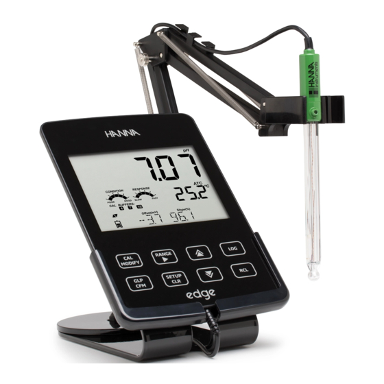
Page 7: Diagram
Front View Liquid Crystal Display (LCD) Micro USB device connection Capacitive Touch Keypad for power or PC interface 3 mm jack input for edge™ Standard USB host connection digital probes for data transfer to a USB Top mounted ON/OFF button…
-
Page 8
Product Diagram Side & Back View Top & Bottom View • Sleek, clean, intuitive design • Basic mode simplified • Internal clock and date operation • Adjustable resolution for pH • Simplified data transfer to a PC and EC measurements •… -
Page 9: Probe Diagram
Probe Diagram Probes pH Electrode EC Electrode DO Electrode • Process measurement signal directly for noise free determinations • Support auto sensor recognition • Store calibration specific data from the last calibration • Are built with materials suitable for use in chemical analysis •…
-
Page 10: Keypad Function
Keypad Function CAL/MODIFY — Used to enter — Used to scroll through and exit calibration mode. In SETUP SETUP menu. Used to change used to initiate modification of a selection when modifying configuration setting. parameter in SETUP. GLP/CFM — Used to display GLP RCL — Used to view log records calibration information.
-
Page 11: Guide To Indicators
Guide to Indicators Mode tags 3rd LCD line, message area Confirm tag 10. Labels USB connection status 11. 2nd LCD line, temperature pH electrode diagnostics measurement Probes symbol 12. Temperature units Battery symbol 13. Temperature status Arrow tags, displayed when 14.
-
Page 12: Setup/Installation
Decide how the meter will be used and set up the wall or bench cradle in a clean area near line power. Turn edge™ on using the ON/OFF button located on the top of the meter. Plug in the probe required for measurement.
-
Page 13
Connect the power adapter cable to the bottom socket of the wall cradle. Connect the probe connector to the socket located at the bottom of edge™. Slide edge™ into the wall cradle. Verify the battery icon indicates charging when meter is powered. -
Page 14: Electrode & Probe Connections
Connect the micro USB connector into edge™ the USB socket on the cradle or into the micro USB socket of edge™. Plug the 5 Vdc adapter into the power supply socket. edge™ can be also powered by connecting with a USB cable directly to a PC.
-
Page 15: General Setup
Choices Default (EC and pH) *Only seen when cable Select to log connection data on edge™ Log on edge™ of Log on edge™ Available between micro or to export data export to PC USB and PC is to PC made.
-
Page 16
General Basic mode* Parameter Description Choices Default (EC and pH) Setup Probe Specific Parameters are inserted here in SETUP list. Set Date Press MODIFY YYYY/MM/DD Set date Available key to Set current Date date, displayed in ISO format. Press CFM to save changes. -
Page 17: Basic Mode
Note: Parameters that are grayed out are seen under special conditions only. Basic Mode edge™ offers a basic operation mode that streamlines measurement configuration for pH and EC measurements and is useful for many routine applications. Basic pH SETUP reduces parameter selection to the basic set.
-
Page 18: Logging Function
Manual and Manual medium stability Log on demand are still functional. Logging Note: • If powering edge™ through the micro USB connector to a PC, a SETUP Function parameter will require the choice “LOG ON EDGE”. • 1000 log records can be stored into the Edge memory. This memory…
-
Page 19
Logging Manual (log on demand) readings are logged each time LOG is pressed. All of the records are stored in a single Manual lot for the measurement type. New Function records made on different days are stored in the same Manual lot. Stability is a log on demand that is made each time LOG is pressed and the stability criterion is reached. -
Page 20
Logging Pressing the LOG key again will stop the Interval logging session. The “LOG STOPPED“ message will Function be displayed for a few seconds. If a sensor failure occurs during interval logging, the message “OUT OF FREE SPACE” will alternate with logging information Manual Logging Select Manual in the SETUP menu. -
Page 21: Viewing Logged Data
The “LOG” tag will be displayed on all 4 screens. All log records stored on edge™ may be viewed on the meter by pressing the RCL key. The log records are grouped according to measurement (pH, EC, DO).
-
Page 22
Viewing If no data was logged for the selected measurement range, the instrument displays the following Logged Data messages (ex. for pH range): No Manual Logs No Stability Logs Press CFM to enter inside lot information to view memorized records. Use the ARROW keys to toggle between different records. -
Page 23
Viewing To delete individual records (Manual and Stability logs only), enter Manual (Stability) log by pressing CFM when Manual (Stability) is displayed. Use the Logged Data ARROW keys to select the record to be deleted and then press CLR. The instrument will display “CLEAR REC.“ and record number along with “CFM” tag blinking. -
Page 24
Viewing Delete All All pH logs, (or all EC, all DO logs) may be deleted in a single clear. This function Logged Data will delete all MANUAL, STABILITY and INTERVAL logs for the measurement type selected. Press the RCL key. The pH, EC, or DO type will be blinking. -
Page 25: Pc & Storage Interface
PC & Storage Logged data on edge™ can be transferred from the meter to a USB flash drive by using the log recall function. The minimum requirement for the drive is USB Interface 1.1. Select the pH, EC or DO record you wish to export and follow the simple steps below.
-
Page 26: Setup/ Installation
PC & Storage Logged data on edge™ can be transferred from the meter to a PC by following these simple directions. The minimum operating system for the PC is Windows Interface Connect the edge™ to the PC using the supplied micro USB cable.
-
Page 27: Operational Guide
Basic vs For optimum pH measurements, follow these steps: Understand the benefits and features of Standard and Basic Operation. Standard Set up edge™ meter by configuring preferences. pH mode Calibration Measurement The “Standard” pH operation includes up to a 5-point buffer calibration, use of custom buffers, choice of displaying 0.001 pH resolution, use of the full…
-
Page 28
Basic vs Major differences between Standard and Basic modes are tabulated below. Standard Standard Basic* pH mode 5 points including 2 custom Calibration 3 points buffers Cal Check™ Feature Basic error messages Sensor Check™ Feature Diagnostics GLP basic Error messages Manual Log on demand Manual Log on demand Log types… -
Page 29: Ph Meter Configurations
pH Meter pH meter operation is configured by using the SETUP key with a pH probe connected to the meter. The parameter-specific parameters will be seen Configuations inserted into the menu. If Basic mode is configured “On”, the pH parameter list will not be displayed.
-
Page 30: Ph Calibration
This includes seven standard buffers and two custom ones. Five pH buffers may Calibration be used for calibration. The instrument should be recalibrated whenever: • High accuracy and sensor verification are required.
-
Page 31
The custom buffers allow the user to calibrate in a buffer solution different from a standard one. Two custom buffers can be set in SETUP menu. See page Calibration 30 for more information about using custom buffers. The instrument will automatically skip the buffer used during calibration and the buffers which are in a ±0.2 pH window, around one of the calibrated buffers. -
Page 32
The “ ” along with “STIR” tag will be displayed and “WAIT” will blink on the LCD until the reading is stable. Calibration When the reading is stable and close to the selected buffer, “CFM” tag will blink. Press CFM to confirm calibration. Repeat procedure with additional pH buffers. -
Page 33
Working With Custom Buffers If a custom buffer was set in SETUP menu, it can be selected during calibration Calibration by pressing the ARROW keys. The “C1” or “C2” tag will be on once selected. Press u if you want to modify the custom buffer value. -
Page 34
INFORMATION. The choice is ON or OFF. Electrode Condition And Electrode Response Time edge™ pH Calibration Check™ feature will assess electrode condition and response time during each calibration and display it for the rest of the day. The condition gauge shows the electrode’s condition that is based on the offset and slope characteristics of the pH electrode at the time of calibration. -
Page 35
This information can also be viewed in the GLP data. Junction Condition (HI 11311 And HI 12301 Only) edge™ pH Sensor Check™ feature will assess the health of the pH electrode’s reference junction during each calibration. The junction gauge may be viewed directly in GLP but will also blink a warning on the display if the junction is compromised (not 100%). -
Page 36
Procedure Basic mode operation permits up to three-point buffer calibration. Calibration For accurate measurements, at least a two-point calibration is recommended. However, a single point calibration can also be used. The calibration buffers can be selected from the calibration buffer list that includes the standard buffers, pH 4.01, 6.86, 7.01, 9.18 and 10.01. -
Page 37
The “ ” along with “STIR” tag will be displayed and “WAIT” will blink on the LCD until the reading is stable. When the reading is stable and close to the Calibration selected buffer, the “CFM” tag will blink. Press CFM to confirm calibration. The calibrated value is then displayed on the 1st LCD line and the third expected buffer value on the 3rd LCD line. -
Page 38: Ph Calibration
used, or clean the electrode by following the Cleaning Procedure (see page 76). If necessary, change the buffer or the electrode. Calibration • If the buffer temperature exceeds the temperature limits of the buffer, “WRONG BUFFER TEMPERATURE” will be displayed. •…
-
Page 39: Calibration Messages
Calibration The Calibration Check™ feature may flag diagnostic messages during a calibration. As electrode aging is normally a slow process, substantial changes Messages from previous calibrations are likely due to a temporary problem with the electrode or buffers that can be addressed easily. These messages are seen in Standard and Basic modes.
-
Page 40
Calibration Clean Electrode This error message indicates poor electrode Messages performance (offset out of accepted window, or slope under the accepted lower limit). Often cleaning the sensor will improve the pH electrodes response. See pH Electrode Conditioning and Maintenance for details. -
Page 41: Ph Glp Information
Calibration Contaminated Buffer This warning message appears in order to alert that Messages the buffer could be contaminated. Refresh your buffer and continue the calibration procedure. pH GLP Good Laboratory Practice (GLP) refers to a quality control function used to ensure uniformity of sensor calibrations and measurements.
-
Page 42
pH GLP The last calibration date (yyyy.mm.dd) together with the current reading. Information Note: For each custom buffer used in calibration, the “C1” and “C2” tags will be displayed. If only the second custom buffer is in calibration the tag will be “C1” and the value will be displayed. -
Page 43: Ph Measurement
pH GLP The probe serial number together with the current reading. Information If a buffer is not from the last calibration, the buffer tag will be displayed blinking. In Standard Mode, Condition, Response gauges are visible on the day of calibration (See Electrode Condition And Electrode Response Time page 34).
-
Page 44
Rinse the pH sensor with water and a sample aliquot if possible. Submerse the electrode tip approximately 3 cm (1¼”) into the sample to be tested and Measurement stir sample gently. Allow time for the electrode to stabilize. The pH is displayed on the 1st LCD line and the temperature on the 2nd LCD line. -
Page 45
Range Specific Messages Displayed On Alphanumeric Line During Measurement (3 Lcd Line) Measurement All the messages described in GENERAL section (page 15) are displayed in pH range. Temperature Sensor Problem (if there is one) Cal Due or Offset and Slope Value Time Date Battery or Charge Status… -
Page 46: Basic Vs Standard Ec Mode
Take measurements using a EC probe. Measurements Available With The EC Probe The four-ring EC probe may be used for 3 different measurement applications with edge™. • It may be used for temperature compensated or absolute conductivity measurements (with units of μS/cm or mS/cm).
-
Page 47: Ec Meter Configuration
Basic vs Measurement data can be logged using Manual Log on Demand or Manual Log on Stability or Interval Logging. The measurement logs may be exported to a Standard thumb drive or PC. EC mode Standard Basic Measurement Conductivity, TDS, Salinity Conductivity, TDS Set up Parameters Fully selectable…
-
Page 48
EC Meter Parameter Description Choices Default Basic mode Configuration T.Coef. (%/ºC) This parameter 0.0 to 6.00 (%/ 1.90 (%/ºC) Not available. is related to the ºC) Note: Setting Close for natural Automatically solution being to 0.00 is the waters or salt set to 1.90%/ºC. -
Page 49
Parameter Description Choices Default Basic mode Configuration EC RANGE If AUTO is used, AUTO, AUTO Not available but the edge™ will 29.99 μS/cm, measurement automatically 299.9 μS/cm, autoranges as find the correct 2999 μS/cm, needed. conductivity 29.99 mS/cm, range and 200.0 mS/cm,… -
Page 50: Ec/Tds Calibration
EC Meter Parameter Description Choices Default Basic mode Configuration EC SALINITY Three PSU, NaCl%, g/L NaCl% Not available. SCALE measurement scales are available for salinity measurement in Seawater. (Practical Salinity Scale, Percent Scale and Natural Seawater Scale). EC Range (Not Available In Basic Mode) The EC and TDS measurements may be configured in SETUP as AUTO (meaning auto-ranging, the measurement automatically finds the correct conductivity or TDS unit and resolution), or it may be configured with a user-selected…
-
Page 51
EC/TDS Every time you calibrate the instrument use fresh standard and perform electrode maintenance as required. It is recommended to chose a calibration CALIBRATION standard that is close to the sample. Preparation Pour small quantities of the standard solutions into a beaker. If possible, use a plastic beaker to minimize any EMC interferences. -
Page 52
EC/TDS When the reading is stable and close to the selected standard, “CFM” tag will blink and the message CALIBRATION “SOLUTION STANDARD” will scroll. Press CFM to confirm calibration. The Instrument displays “SAVING”, stores the calibration values and returns to measurement mode. Operational Guide… -
Page 53
EC/TDS The following table lists the temperature dependence of Hanna EC calibration standards. edge™ uses these values during calibration and their temperature CALIBRATION coefficients. HI7030 HI7031 HI7033 HI7034 HI7035 HI7039 ºC ºF HI8030 HI8031 HI8033 HI8034 HI8035 HI8039 (μS/cm) (μS/cm) (μS/cm) -
Page 54: Nacl Calibration
% NaCl PREPARATION Pour a small quantity of the calibration solution into a beaker. If possible, use CALIBRATION a plastic beaker to minimize any EMC interferences. Before pressing CAL verify in SETUP: • Basic mode is off • Salinity Scale is NaCl% Use the RANGE key to select the Salinity measurement.
-
Page 55: Ec/Tds Glp Information
% NaCl The Instrument displays “SAVING”, stores the calibration values and returns to measurement mode. CALIBRATION Note: If a new EC calibration is performed, the NaCl calibration is automatically cleared. A new NaCl calibration is required. Wrong Standard If the reading is too far from the expected value, the Calibration “WRONG STANDARD”…
-
Page 56
EC/TDS To view the EC calibration data, press GLP when the instrument is in EC measurement mode. The instrument will display the calibration standard and the temperature of the calibrated standard. Use the ARROW keys to scroll Information through the calibration data displayed on the 3rd LCD line. The cell factor in cm determined from the calibration with the current reading. -
Page 57
EC/TDS The last calibration time (hh:mm:ss) together with the current reading. Information The last calibration date (yyyy.mm.dd.) together with the current reading. Calibration Expiration status together with the current reading: If disabled, “EXPIRATION WARNING DISABLED” is displayed If enabled, the number of days until the calibration alarm “CAL DUE”… -
Page 58
NaCl% measurement mode. Use the ARROW keys to scroll through the Information calibration data. The instrument will display the calibration temperature and solution. The edge™ will indicate: probe cell constant together with the current reading. The salinity coefficient determined from the calibration together with the current reading. -
Page 59
EC/TDS Calibration Expiration status together with the current reading: If disabled, “EXPIRATION WARNING DISABLED” is Information displayed If enabled, the number of days until the calibration alarm “CAL DUE” will be displayed. Or if the number of days the calibration has expired ( I.E. -
Page 60
EC/TDS The RANGE key will change measurement from conductivity to TDS to Salinity. Measurements Conductivity Measurements Connect the conductivity probe to the instrument and wait until probe parameters are loaded. The following message is then displayed on the LCD: “Probe Connected” Verify if the probe has been calibrated. -
Page 61: Ec/Tds Measurements
EC/TDS No Temperature Compensation (No TC): The temperature value is displayed, but not taken into account. When this option is selected, the “NoTC” tag will Measurements be displayed. The reading displayed on the primary LCD is the uncompensated EC or TDS value. Note: •…
-
Page 62: Salinity Measurements
Salinity Salinity Measurements (Not Available In Basic Mode) Press the RANGE key twice to switch from conductivity to the configured Measurements Salinity scale. Verify the desired scale is configured in SETUP. The meter supports three salinity scales: Practical Scale 1978, Percent Scale %, and Natural Sea Water 1966, [g/L].
-
Page 63
Salinity — ratio of sample conductivity to standard conductivity at Temp =(T) CT(sample)-conductivity at T ºC; Measurements C(35,15)=42.914µS/cm — the corresponding of KCI solution containing a mass of 32.4356 g KCl/1 Kg solution — Temperature compensation polynomial = 0.008 = 0.0005 = -0.1692 = -0.0056 = 25.3851… -
Page 64: Salinity Measurements
Salinity Natural Sea Water Scale The Natural Sea Water Scale extends from 0 — 80.0 g/L. It determines salinity Measurements based upon a conductivity ratio of sample to “standard seawater” at 15 °C. Where R is the conductivity ratio and salinity is defined by the following equation: S = — 0.08996 + 28.2929729R + 12.80832R…
-
Page 65: Dissolved Oxygen Setup
Measurements Available Concentration measurements in water, and % oxygen saturated measurements are available using edge™ together with HI 764080 DO probe. Algorithms used for concentration measurements (units of ppm or mg/L) are based upon the oxygen solubility in air-saturated fresh water. Compensation for salinity and altitude are made by configuring SETUP parameters.
-
Page 66
The cathode area should be free of bubbles. Setup 8. Connect the DO probe to the edge™ meter and turn meter on 9. Allow probe conditioning function to occur. Note: When not in use and during polarization, use the protective transparent cap. -
Page 67: Do Probe Diagram
DO Probe Diagram Strain Relief Probe Cap PEI Probe Body Temperature Sensor Threads for Membrane Cap Ag/AgCl Anode and Reference Glass Insulator Platinum Cathode O-Ring 10. Disposable Membrane Cap 11. Oxygen Permeable PTFE Membrane 12. Shipping Tube Operational Guide…
-
Page 68: Do Meter Configuration
DO Meter DO (Dissolved Oxygen) meter operation is configured using the SETUP key with a DO probe connected to the meter. The parameter-specific parameters Configuration will be seen inserted into the menu. There is no Basic mode for Dissolved Oxygen measurements. Parameter Description Choices…
-
Page 69
Compensation for temperature-related solubility is done automatically using the built-in temperature sensor within the DO probe and algorithms in the edge meter. When water is measured at an altitude below sea level, oxygen solubility increases, but above sea level the oxygen solubility decreases. -
Page 70: Do Meter Configuration
DO Meter When water is fresh containing no sea water, the concentration of oxygen will be at a maximum. The solubility of the oxygen dissolved in water is decreased Configuration when water is brackish or seawater. The solubility of oxygen in water is decreased when measurements are made at elevations above sea level.
-
Page 71: Do Calibration
When the reading is stable and is within the limits, “CFM” tag starts blinking. Press CFM to confirm the Calibration 100.0 % DO calibration. Press CAL to leave calibration after the first point. The instrument will display “SAVING” message and it will return to measurement mode memorizing the slope calibration data.
-
Page 72: Do Calibration Messages
Calibration Messages If the reading is outside limits, “WRONG STANDARD“ Calibration message will be displayed. Messages If the temperature goes out of (0.0 — 50.0 ºC) range during calibration, the “WRONG STANDARD TEMPERATURE” message will be displayed and temperature value will blink. DO GLP GLP refers to a quality control function used to ensure uniformity of probe calibrations and measurements.
-
Page 73
DO GLP The altitude and salinity setting at the moment of calibration together with the current reading. Information The time of the calibration together with the current reading. The date of the calibration together with the current reading Calibration Expiration status together with the current reading: If disabled, “EXPIRATION WARNING DISABLED”… -
Page 74
DO GLP The probe serial number together with the current reading Information Make sure that the probe is polarized, calibrated and the protective cap has been removed. Measurements Rinse probe. Submerse the probe in the sample to be tested, make sure temperature probe is also immersed. -
Page 75: Do Measurements
any measurement. This can take several minutes. The greater the difference between the temperature at which the probe was stored and the temperature Measurements of the sample, the longer the time will be. Note: • If the temperature is displayed blinking, the temperature is out of range for the probe.
-
Page 76: Maintenance
pH Probe Maintenance Remove the protective cap of the pH electrode. DO NOT BE ALARMED IF SALT DEPOSITS ARE PRESENT. This is normal with electrodes. They will disappear when rinsed with water. During transport, tiny bubbles of air may form inside the glass bulb affecting proper functioning of the electrode.
-
Page 77
pH Probe For refillable electrodes: If the filling solution (electrolyte) is more than 2½ cm (1”) below the fill hole, Maintenance add HI 7082 or HI 8082 3.5M KCl Electrolyte Solution for double junction. Unscrew the fill hole cover during measurements so the liquid junction maintains an outward flow of electrolyte. -
Page 78
pH Probe Cleaning Procedure Use diagnostic messages to aid pH electrode troubleshooting. Several Maintenance cleaning solutions are available: General – Soak in Hanna HI 7061 or HI 8061 General Cleaning Solution for approximately ½ hour. Protein –Soak in Hanna HI 7073 or HI 8073 Protein Cleaning Solution for 15 minutes. -
Page 79: Ec Probe Maintenance
pH Probe Alkaline Error High concentrations of sodium ions interfere with readings in alkaline Maintenance solutions. The pH at which the interference starts to be significant depends upon the composition of the glass. This interference is called alkaline error and causes the pH to be underestimated. Hanna’s glass formulations have the indicated characteristics.
-
Page 80: Do Probe Maintenance
DO Probe The oxygen probe body is made of PEI. A temperature sensor provides temperature measurements of the sample. Maintenance Use the protective cap when the probe is not in use. To replace the membrane or refill with electrolyte, proceed as follows: Remove the protective shipping tube by gently twisting and pulling it off the body of the probe (see fig.
-
Page 81: Do Probe Maintenance
DO Probe The platinum cathode (DO Probe Diagram, page 67) should always be bright and untarnished. If it is tarnished or stained, the cathode should be cleaned. Maintenance You can use a clean lint-free cardboard or cloth. Rub the cathode very gently side to side 4-5 times.
-
Page 82: Troubleshooting Guide
Troubleshooting Symptoms Problems Solution Guide Clean the electrode and then soak Slow response/excessive Dirty pH electrode. the tip in HI 7061 or HI 8061 for 30 drift. minutes. pH: Clogged/dirty Clean the electrode. Refill with fresh junction. Low electrolyte solution (for refillable electrodes only). level (refillable Check cable and connectors.
-
Page 83
Troubleshooting Symptoms Problems Solution Guide A) Verify the shipping cap has been removed. B) Make sure the sample pH is within If the display shows: Out of range in the mV specified range. “mV” and “-1000” or scale. C) Verify electrolyte level in pH sensor “1000”… -
Page 84: Specifications
Specifications Temperature -2.00 to 16.00 pH Range -2.000 to 16.000 pH* -20.0 to 120.0 ºC (-4.0 to 248.0 °F)** ±1000.0 mV 0.01 pH Resolution 0.001 pH* 0.1 ºC 0.1 mV ±0.01pH Accuracy ±0.002 pH* ±0.5 ºC @ 25 °C / 77 °F ±0.2 mV Automatic, up to 3 points (5 points*) calibration, 5 standard (7 pH Calibration…
-
Page 85
Specifications Salinity 0.00 to 29.99 μS/ cm, 3.00 to 29.99 0.00 to 14.99 ppm μS/cm, 300. to (mg/L), 15.0 to 149.9 2999. μS/cm, ppm (mg/L), 150. to 0.0 to 400.0% NaCl 3.00 to 29.99 1499. ppm (mg/L), 1.50 **, 2.00 to 42.00 Range mS/cm, 30.0 to to 14.99 g/L, 15.0 to… -
Page 86
Specifications Conductivity temperature 0.00 to 6.00% / ºC (for EC and TDS only). Default value is 1.90% / ºC coefficient TDS factor 0.40 to 0.80 (default value is 0.50) EC Probe HI 763100 Up to 1000 ** (400) records organized in: Manual log on demand (Max. 200 Log feature logs), Manual log on stability (Max. -
Page 87
Specifications 0.00 to 45.00 ppm (mg/L) Range 0.0 to 300.0% -20.0 to 120.0 ºC (-4.0 to 248.0 °F)* 0.01 ppm (mg/L) Resolution 0.1% 0.1 °C Accuracy ±1.5% of reading or ±1 digit @ 25 °C / 77 °F ±0.5 ºC DO Calibration One or two points at 0% (HI 7040) and 100% (water saturated air) Altitude Compensation… -
Page 88: Accessories
Accessories Buffer Solutions HI 70004P pH 4.01 Buffer Sachets, 20 mL (25 pcs.) HI 70007P pH 7.01 Buffer Sachets, 20 mL (25 pcs.) HI 70010P pH 10.01 Buffer Sachets, 20 mL (25 pcs.) HI 7001L pH 1.68 Buffer Solution, 500 mL HI 7004L pH 4.01 Buffer Solution, 500 mL HI 7006L…
-
Page 89
Accessories Conductivity Solutions HI 70030P 12880 μS/cm, 20 mL sachets (25 pcs.) HI 70031P 1413 μS/cm, 20 mL sachets (25 pcs.) HI 70039P 5000 μS/cm, 20 mL sachets (25 pcs.) HI 7030M 12880 μS/cm, 230 mL bottle HI 7031M 1413 μS/cm, 230 mL bottle HI 7033M 84 μS/cm, 230 mL bottle HI 7030M… -
Page 90: Accessories
HI 2000WC Wall cradle HI 2000BC Bench cradle Ordering Information HI 2020-01 edge™ instrument with US plug HI 2020-02 edge™ instrument with EU plug HI 11310 Glass body, double junction, pH/temperature electrode Glass body, double junction, pH/temperature electrode with enhanced…
-
Page 91: Warranty
Technical Service department and then send it with shipping costs prepaid. When shipping any instrument, make sure it is properly packed for complete protection. Hanna Instruments reserves the right to modify the design, construction or appearance of its products without advance notice. Warranty…
-
Page 92
Notes Warranty… -
Page 93
Notes Warranty… -
Page 94
Notes Warranty… -
Page 95
Notes Warranty… -
Page 96
World Hanna Instruments Inc. Highland Industrial Park Headquarters 584 Park East Drive Woonsocket, RI 02895 www.Hannainst.com Local Office Hanna Instruments USA 270 George Washington Highway Smithfield, RI 02917 Phone: 800.426.6287 Fax: 401.765.7575 e-mail: tech@Hannainst.com…
Руководства пользователя, инструкции и руководства для продуктов EDGE.
Найти
EDGE EDB80.2LITE-E0 Серия DB, 2 канала, 320 Вт Amplifier Внимание! Поздравляем с приобретением EDGE. ampЛифер. Пожалуйста, прочитайте это руководство, чтобы полностью понять, как получить наилучшие результаты от этого продукта, и убедитесь, что все рекомендации по уходу за продуктом выполняются. Благодарим вас за покупку EDGE, мы надеемся…
Подробнее «EDGE EDB80.2LITE-E0 DB Series, 2 канала, 320 Вт Ampруководство пользователя lifier »
Edge 540 V3 1 м V2.0 T101 540 V3 1 м RC Размах крыльев EPP Версия 2022 Желаем вам долгих летных часов с Edge 540 V3 Your RC Factory team.
EDGE серии DBX, 4 канала, 1600 Вт Amplifier Внимание! ampLifier создаст дополнительную нагрузку на систему зарядки транспортных средств. Большинство современных автомобилей имеют достаточную мощность в системе зарядки, так как не все электрические компоненты автомобиля включаются одновременно. Проверьте номинал предохранителя ampпожизненнее…
Подробнее «EDGE DBX Series 4 Channel 1600 Вт Ampруководство пользователя lifier »
EDGE EDBX2200.1D-E1 Моноблок 4400 Вт Amplifier Руководство пользователя Поздравляем с приобретением EDGE! ampЛифер. Пожалуйста, прочитайте это руководство, чтобы полностью понять, как получить наилучшие результаты от этого продукта, и убедитесь, что все рекомендации по уходу за продуктом выполняются. Благодарим вас за покупку EDGE, надеемся, вам понравится…
Подробнее «EDGE EDBX2200.1D-E1 Моноблок 4400 Вт AmpРуководство пользователя lifier »
РУКОВОДСТВО ПОЛЬЗОВАТЕЛЯ САБВУФЕРА EDGE Поздравляем с покупкой сабвуфера EDGE. Пожалуйста, прочтите это руководство, чтобы полностью понять, как добиться наилучших результатов от этого продукта, и убедиться, что соблюдаются все советы по уходу за изделием. Благодарим вас за покупку EDGE, надеемся, что вам понравится слушать ваш продукт…
Подробнее «Руководство пользователя EDGE SUBWOOFER»
В настоящее время вы находитесь на странице с руководствами . Выберите одну из категорий продуктов, чтобы быстро найти нужное руководство . Не удалось найти нужный продукт ? Тогда попробуйте вбить в строку поиска и модель, чтобы найти нужное руководство . На ManualsPDF.ru в настоящее время имеется 11 руководств , разделенных на 4. Самые популярные категории продуктов :
- USB-накопители
- Твердотельные накопители (SSD)
- Внешние жесткие диски
Самые популярные продукты из на сегодня:
- Edge DiskGO Secure Pro
- Edge Boost Pro
- Edge DiskGO Mini Portable