Корректор газа потоковый ЕК280 продолжает линейку корреторов серии ЕК и представляет более широкий функционал по сравнению с корректором ЕК270. Корректор газа потоковый ЕК280 предназначен для приведения рабочего объема газа, прошедшего через счетчик, к стандартным условиям (давление газа — 760 мм. рт.ст., температура газа +20°С) путем вычисления коэффициента сжимаемости газа и коэффициента коррекции с использованием измеренных значений давления, температуры газа и введенных параметров газа.
Подключение дополнительных преобразователей давления и перепада давления, наличие цифровых входы и выходов позволяет организовать на базе ЕК280 систему контроля и управления.
Преобразователи давления и температуры
В отличие от корректора ЕК270 корректор EK280 может быть оснащен до 6 преобразователей давления (2 аналоговых и 4 цифровых) и до 4 преобразователей температуры.
Преобразователи давления используются для изменения абсолютного давления на счетчике (Pa), измерения перепада давления на счетчике и измерения давления еще в одной точке трубопровода, например, перед фильтром.
Преобразователи температуры используются для измерения температуры газа в счетчике и для измерения температуры окружающей среды.
Измеренные и вычисленные данные хранятся в энергонезависимом архиве корректора ЕК280.
Подключение СЧ и ВЧ датчиков и датчиков различного функционала
Наличие высокочастотного входа позволяет подключить к корректору ЕК280 среднечастотный датчик импульсов R300 или высокочастотные датчики импульсов A1K (для RVG) и А1S (для TRZ) и точно вычислять мгновенный расход газа не только при стабильном, но и при импульсном режиме работы оборудования.
Дополнительные НЧ/ВЧ входы позволяют подключить к корректору ЕК280 различные датчики, например датчики загазованности и/или датчики контроля периметра.
Методы вычисления коэффициента сжимаемости
Дополнительно к методам вычисления коэффициента сжимаемости NX19 мод и GERG-91 мод, которые применяются в ЕК270, в корректоре ЕК280 добавлен метод МР113, использующийся для вычисления коэффициента сжимаемости попутного нефтяного газа. Таким образом, корректор ЕК280 может использоваться совместно со счетчиками для учета попутного нефтяного газа.
Независимые интерфейсы RS232/RS485 и встроенный GSM/GPRS модем
Корректор EK280 в дополнение к оптическому и RS232/RS485 интерфейсам может быть оснащён ещё одним RS232/RS485 интерфейсом или встроенным GSM/GPRS модемом с внешней антенной.
В этом случае проводные интерфейсы RS232/RS485 полностью независимы друг от друга и позволяют одновременно передавать данные. Таким образом, и поставщик, и потребитель газа могут иметь одновременный доступ по проводному интерфейсу к корректору EK280.
Модем устанавливается внутри корпуса корректора и использует для питания дополнительный элемент питания. Использование встроенного GSM/GPRS модема позволяет организовать дистанционную передачу данных о потреблении газа на сервер сбора данных в тех местах, где нет возможности подключения дополнительного внешнего питания к корректору ЕК280. В этом случае интерфейсы также полностью независимы друг от друга.
Надежный металлический корпус обеспечивает простоту подключения вторичных устройств и допускает установку корректора на турбинный или ротационный счетчик газа, а так же на стену.
Многоточечный дисплей с крупными символами и подсветкой, в совокупности с семикнопочной клавиатурой, обеспечивают удобный для восприятия интерфейс оператора.
Оптический интерфейс передачи данных, расположенный на лицевой панели, позволяет производить настройку корректора и считывание архивов без коммутации соединительных кабелей. Встроенный в корпус корректора ЕК280 GSM/GPRS модем значительно упрощает процесс дистанционного сбора данных.
-
Contents
-
Table of Contents
-
Bookmarks
Quick Links
3
Operating manual
Volume conversion device
EK280
Related Manuals for Elster EK280
Summary of Contents for Elster EK280
-
Page 1
Operating manual Volume conversion device EK280… -
Page 2
Volume conversion device EK280 Operating manual: 73021209 Version: Issue date: 25.10.13 Software-Version: 2.20 or later… -
Page 3: Table Of Contents
3 Technical data ………………19 3.1 General data ………………19 3.2 Power supply for EK280 without integrated power supply unit ..19 3.2.1 Battery power supply for the basic device ……….. 19 3.2.2 Battery power supply for the integrated modem ……..19 3.2.3 External power supply for the basic device ………
-
Page 4
5.2.6 Connect outputs of the EK280 …………39 5.2.7 Earthing the EK280 housing …………… 40 5.2.8 Earthing the cable connections of the EK280 ……..40 5.2.9 Additional measures for installation in zone 2 ……..41 5.3 Putting into operation …………… 41 5.3.1 Configuration of measurement parameters ……… -
Page 5
General 5.3.4 Verifying assembly and connection …………. 52 6 Operation ………………..53 6.1 Safety ………………..53 6.1.1 Personal protective equipment …………53 6.2 Operating personnel ……………. 53 6.2.1 Instructed personnel …………….53 6.2.2 Qualified personnel …………….53 6.2.3 Calibration officers…………….54 6.3 Basic principles ……………. -
Page 6
General 9 Appendix ………………..82 9.1 List of spare parts and accessories ……….82 9.1.1 Fastening elements …………….82 9.1.2 Pressure connections…………….82 9.1.3 Temperature sensor pockets ………….. 83 9.1.4 Small parts and miscellaneous …………83 9.1.5 Documentation ………………83 9.2 EC Declaration of Conformity ………… -
Page 7: General
The data and material properties indicated serve as reference val- ues. These must be verified on a case-by-case basis and adjusted as necessary. The EK280 Application Manual is available for you at www.elster- instromet.com/en/EK280.html (-> Documents) for the commission- ing of the various communication and device applications.
-
Page 8: Electronic Hotline
In the event of faults, you can also contact the electronic hotline. Tel. +49 (0) 6134 / 605-123 http://www.elster-instromet.com/en/support_electronics.html E-mail: support@elster.com 1.4 Meaning of symbols 1.4.1 Safety information In this manual, safety information is denoted by the use of symbols. The safety in- formation is introduced by signal words which identify the level of risk.
-
Page 9: Tips And Recommendations
General 1.4.2 Tips and recommendations … provides useful tips and recommendations as well as infor- mation for ensuring efficient and smooth operations. 1.5 Limitationof liability All of the information contained in this manual has been compiled under considera- tion of valid standards and regulations, the latest technological developments, and our many years of experience and expertise.
-
Page 10: Scope Of Delivery
The free «enSuite» program also belongs to the accessories for the EK280 and is available under www.elster-instromet.com. This can be used to program the EK280 volume conversion device via its data interfaces to perform advanced applications.
-
Page 11: Storage
General 1.9 Storage CAUTION! Exceeding or falling below the valid temperature range for the batteries may impair performance. If the valid temperature range of the batteries during storage of the device is exceeded or fallen below, the performance of the batter- ies may be impaired.
-
Page 12: Safety
– If category «II 3 G» has been marked on the ATEX label, the EK280 should not be used in zone 1, but only in zone 2. – The ATEX label is located on the top panel of the EK280 hous- ing.
-
Page 13
Operating the EK280 in zone 1 and connecting devices which are not certified as «associated equipment» present a risk of explosion. Therefore: – When using the EK280 in zone 1, it should only be connected to certified associated equipment as per the ATEX Product Di- rective 94/9/EC. -
Page 14: Intended Use
This device is solely designed and constructed for the intended use described be- low. The volume conversion device EK280 is used to convert the gas volume read from a gas pipe under measurement conditions, into base conditions, as well as to allo- cate the measured quantities to tariffs.
-
Page 15: Personal Protective Equipment
Safety Gas specialists who, on the basis of their specialist training, knowledge and experience, as well as their awareness of the relevant standards and regulations, are in a position to perform works on gas-handling equipment and to independently identify possi- ble risks.
-
Page 16: Specific Risks
Safety 2.5 Specific risks The residual risks arising from the risk assessment will be listed below. Please ob- serve the safety and warning information specified in the following chapters to re- duce risks to health and to prevent dangerous situations from arising. WARNING! Misuse of batteries may present a risk of injury.
-
Page 17: Environmental Protection
Safety 2.6 Environmental protection CAUTION! Environmentally hazardous substances! If environmentally hazardous substances are handled incorrectly this may cause significant damage to the environment, particularly if they are improperly dis- posed of. Therefore: – The instructions below should be observed at all times. –…
-
Page 18: Operator’s Responsibility
Safety 2.7 Operator’s responsibility The device will be used in the commercial sector. The operator of the device will therefore be subject to legal obligations concerning occupational safety. In addition to the safety information contained in these instructions, the valid safety, accident prevention, and environmental protection regulations for the area of appli- cation of the device, must be adhered to.
-
Page 19: Technical Data
Permissible ambient temperature range -25 … +55 °C Permissible gas temperature range -30 … +60 °C 3.2 Power supply for EK280 without integrated power supply unit 3.2.1 Battery power supply for the basic device Data Value Unit Voltage General nominal capacity 16.5…
-
Page 20: External Power Supply For The Basic Device
Supply voltage 7.5 …8.5 Supply current, maximum 3.3 Power supply for EK280 with integrated power supply unit 3.3.1 Battery power supply for the basic device Batteries for switching to battery mode in the event of a power failure: see chapter 3.3.1 «Battery power supply for the basic device»…
-
Page 21: Pressure Sensor Type 17002
16 … 80 bar abs. 105 bar abs. The pressure sensor is available as both an external and internal model. Further details can be found under www.elster-instromet.com or chapter «Assembly, Connection and Putting into Operation». 3.4.1.2 Relative pressure ranges Measuring range Overload capacity ……
-
Page 22: Temperature Sensor
Technical data The pressure sensor is available as both an external and internal model. Further details can be found under www.elster- instromet.com or chapter «Assembly, Connection and Putting into Operation». 3.5 Temperature sensor Data Value Unit Measuring range -30 … +60 °C…
-
Page 23: Hf Pulse Inputs (High Frequency)
Technical data 3.6.2 HF pulse inputs (high frequency) High frequency pulse transducers can only be connected to inputs 1 and 2 (termi- nals DE1 and DE2) (see chapter 5.2.1.3). Data Value Unit Open-circuit voltage 7.5 … 8.5 «High» switching level max.
-
Page 24: Hf Pulse Outputs
Technical data 3.7.3 HF pulse outputs The use of outputs as high frequency output is only possible if an external power supply has been connected (see chapter 5.2). Only outputs 2 and 3 (terminals DA2 and DA3) can be used as high frequency out- put.
-
Page 25: Labeling
(MID). The label is placed on the front panel of the device (see Construction and Function chapter). 3.10.1 Type label of the volume corrector The type label of the EK280 relating to its function as a volume corrector, contains the following information: 1 Type designation EK280…
-
Page 26: Atex Marking
Technical data 3.10.2 ATEX marking The plate for the «Ex» marking of the EK280 is located on the top panel of the de- vice housing. 3.10.2.1 Zone 1 (without integrated power supply unit) ELSTER GmbH II 1 G 55252 Mainz- Kastel…
-
Page 27: Construction And Function
Construction and Function 4 Construction and Function 4.1 External view 1 Display 2 Cable bushings for the connec- tion of additional components 3 Optical interface Identification label 4 Escape button «ESC» 5 Enter button «ENTER» 6 Function key , ⊳ 7 Arrow keys 8 Pressure sensor Instromet…
-
Page 28: Short Description
Construction and Function 4.3 Short description The volume conversion device EK280 is an explosion-protected electronic device that takes the volume of gas determined by an external meter at measurement con- ditions to calculate the volume at base conditions and therefore the energy portion of the respective gas volume.
-
Page 29: Assembly, Connection And Putting Into Operation
– Do not open when an explosive atmosphere may be present! – Electrostatic hazard: Do not rub! The EK280 can either be mounted on a gas meter, on a pipeline, or on a wall. Should problems arise during assembly, e.g. with regard to the selec- tion of suitable assembly tools, please contact our customer service team (see «General»…
-
Page 30: Assembly On A Gas Meter
Assembly, Connection and Putting into Operation 5.1.1 Assembly on a gas meter Mount the EK280 on a gas meter using a mounting bracket (see Ap- pendix) as well as the corresponding cylinder screws and square nuts. 1. Using two M5 x 10 mm (Fig. 6: cylinder screws, attach the mounting bracket (Fig.
-
Page 31: Assembly On A Wall
Select wall plugs which corre- spond to the size of the screws and insert these in the boreholes in the wall. To fasten the EK280, four M5 x 40 mm wood screws should be used for wall as- sembly. Fig. 8 5.1.4 Three-way valve…
-
Page 32: Connection
The connection of non intrinsically-safe or non-associated equipment presents a risk of explosion! The operation of the EK280 in zones 1 and 2 and the connection of non intrinsically-safe equipment which exceeds those conditions and limit values specified in the declaration of conformity, presents a risk of explosion.
-
Page 33: Connecting The Gas Meter
5.2.1 Connecting the gas meter In order to measure the gas volume, a gas meter with a low or high frequency pulse transducer or encoder can be connected to the digital input «DE1» of the EK280. The pulse transducer or encoder of the gas meter will be connected to the «DE1″…
-
Page 34
— not when in battery mode. In order to ensure an uninterrupted measurement of the gas volume, the EK280 can be configured in such a way that the device automatically switches to a low fre- quency pulse transducer in the event of a failure of the external power supply;… -
Page 35: Sealing The Input Terminals
Assembly, Connection and Putting into Operation 5.2.2 Sealing the input terminals After connecting to the gas meter as per chapter 5.2.1, the input terminal «DE1» must be sealed for official calibration measurements. For this purpose, terminal covers are provided in the bag of accessories. If required, these should be screwed over the connected terminals and an adhesive seal should then be bonded to the fastening screw (see chapter 5.3.2).
-
Page 36: Connecting The Pressure Pipe
Assembly, Connection and Putting into Operation 5.2.3.2 Connection to an older temperature sensor pocket Insert the temperature sensor Pt500 into the temperature sensor pocket (see Appendix). Use the adapter to seal the connec- tion (see Appendix). Fasten the temperature sensor using the capstan screw and the screw connections…
-
Page 37: Connecting The Power Supply
Operating the EK280 in zone 1 and connecting devices which are not certified as «associated equipment» present a risk of explosion. Therefore: – When using the EK280 in zone 1, it should only be connected to certified associated equipment as per the ATEX Product Di- rective 94/9/EC.
-
Page 38
Assembly, Connection and Putting into Operation 5.2.5.2 Power supply for the EK280 with integrated power supply unit DANGER! Danger to life from electrical current! Touching live parts poses an imminent danger to life. Therefore: – Works on the electrical components of the device, i.e. the con- nection of the power supply unit, should solely be carried out by qualified electricians. -
Page 39: Connect Outputs Of The Ek280
Assembly, Connection and Putting into Operation 5.2.6 Connect outputs of the EK280 The cable core diameter for the connection to the EK280 outputs is 0.33 … 2.5 mm Different downstream devices can be connected to the digital out- puts of the EK280. The outputs are preconfigured for this purpose (see chapter 5.3.1.13).
-
Page 40: Earthing The Ek280 Housing
Use the cable to connect the screw on the left-hand side of the housing with the equipotential bonding strip. 5.2.8 Earthing the cable connections of the EK280 All cables firmly connected to the EK280 have a shield. This is connected to the cable glands of the EK280 in order to prevent electromagnetic interference.
-
Page 41: Additional Measures For Installation In Zone 2
8 mm M16, plastic: 8 mm The ATEX category «II 1 G» models of the EK280 (without in-built power supply unit) should be installed in both zones 1 and 2 without these additional measures. 5.3 Putting into operation 5.3.1 Configuration of measurement parameters If the EK280 is subject to calibration regulations, the works described below should only be performed by legally authorized individuals.
-
Page 42
Assembly, Connection and Putting into Operation 5.3.1.1 Opening the calibration lock The calibration lock is located at the back of the housing cover in the form of a but- ton, and this can be secured by means of an adhesive label. This button must be pressed in order to adjust the values and parameters protected by configuration regulations. -
Page 43
If an encoder is connected as per 5.2.1.2, the encoder mode is activated as follows: Start the «Auto Detect» function using the keyboard of the EK280 as follows: Move the cursor to the «Serv.» register and to the value «Md.I1» (input mode) via the following path: Serv. -
Page 44
Assembly, Connection and Putting into Operation 5.3.1.4 Adjusting the parameters for the high frequency pulse transducer of the gas meter If a high frequency pulse transducer is connected as per 5.2.1.3, the input mode and the cp value should be adjusted as follows: 1. -
Page 45
In order to control the recording of the volume at measurement conditions, the EK280 meter can be set once to the same value as the gas meter if the administra- tor lock is open. It is always possible to set the volume if the calibration lock is open: Open the administrator lock or the calibration lock Move the cursor to the „Serv.“… -
Page 46
5.3.1.8 Setting the volume at base conditions For the EK280 volume conversion device, there is the option available when com- missioning the device to set the volume at base conditions meter once if the admin- istrator lock is open. It is always possible to set the volume if the calibration lock is… -
Page 47
Assembly, Connection and Putting into Operation 5.3.1.9 Deleting change information for comparison of Vb with the gas meter In order to allow the volume at base conditions to be reset if the administrator lock is open, the change information for comparison of „Vb“ must be deleted: Open the calibration lock Move the cursor to the „Serv. -
Page 48
Assembly, Connection and Putting into Operation 5.3.1.11 Adjust alarm limits for gas pressure and temperature measurement Alarm limits are set to default values ex-factory. If a change becomes necessary, please proceed as follows: Move the cursor to the «Serv.» register and move to the alarm limit values via the following paths: Serv. -
Page 49
Aside from the settings described here, a range of other functions can be configured for the outputs, e.g. high frequency or time- synchronous pulses. A complete description can be found in the EK280 Application Manual that can be downloaded under www.elster-instromet.com. 5.3.1.14 Setting the daylight saving time Move the cursor to the «Serv.»… -
Page 50
All measurement archives (no logs) will be deleted. In order to ensure that the archive is not accidentally deleted, the serial number of the EK280 must be entered whilst the calibration lock is open (the number is located on EK280 identification plate). -
Page 51: Sealing
Assembly, Connection and Putting into Operation 5.3.2 Sealing 5.3.2.1 External view Possible sealing point to se- cure the identification plate via adhesive seal. EK280 Year: 2011 Optional user lock: Seal co- Serialno.: 1234567 M 11 0102 vers using wire seals through…
-
Page 52: Closing The Housing
Fig. 22 5.3.4 Verifying assembly and connection WARNING! Risk as a result of incorrect assembly and connection Incorrect assembly and connection of the EK280 may lead to life- threatening situations. Therefore: – Assemble and connect the EK280 correctly. – Sealing should solely be carried out by a calibration officer.
-
Page 53: Operation
EK280, and to perform changes which are not subject to calibra- tion regulations.
-
Page 54: Calibration Officers
EK280, and to perform changes which are not subject to calibra- tion regulations. 6.3 Basic principles As already explained in the «Construction and Function»…
-
Page 55: Display
Operation 6.3.1 Display The display is divided into the five registers «Main», «Cust.», «Admin», «Serv.» and «Ctrl.» under which measurements, settings and other data are displayed. Fig. 24 Display layout Device status Battery charge status Frozen display Active register External power supply Inactive register Reception strength of the external Cursor…
-
Page 56: Button Functions
Operation 6.3.2 Button functions The pressure and arrow buttons have the following functions: Button Function Jump right to another data list. Jump to the second part of a two-part value. Jump down through a data list. ⊳ Jump left to another data list. Jump up through a data list.
-
Page 57: Data Recall, Display Navigation
Operation 6.3.3 Data recall, display navigation ⊳ Using the arrow keys , you can move the cursor around the display and switch to the other values. By pressing the ESC button one or more times, you will be directed to the «Main», «Cust.», «Admin», «Serv.»…
-
Page 58: Meaning Of Status Symbols
Operation 6.3.4 Meaning of status symbols The status symbols displayed in the first line have the following meaning: Fig. 26: Status symbols in the display Symbol Meaning In the upper left-hand side of the screen, individual letters are dis- played as symbols for the following signals: No special message.
-
Page 59: Error Messages When Entering Values
External power supply If this symbol appears, the EK280 is being supplied power from an ex- ternal unit connected to the terminals. Signal strength of the radio network for the external modem (connected to the terminals).
-
Page 60: Access Rights
As this address has not yet been entered, no value will be displayed. The value can only be changed when the calibration lock is open as the PTB log is full. 6.3.6 Access rights The following parties can access the EK280. Access Meaning Calibration officer…
-
Page 61
This includes all values which influence volume readings or the volume conversion. The calibration lock is designed as a button which is positioned inside the EK280 housing underneath the circuit board cover. It can be protected with an adhesive la- bel (see chapter 5.3.1.1, «Opening the calibration lock»). -
Page 62: Data Register Content
Operation 6.3.6.3 Administrator and customer locks Administrator and customer locks are used to protect data which is not subject to calibration regulations, but which should also not be modified without authorization. These locks can be opened by entering a code (i.e. the «key») under “Cod.A” or “Cod.C”…
-
Page 63
The calculated compressibility ratio factor is used to calculate the volume at base conditions. The EK280 supports several equations to calculate the compressibility ratio factor. The corresponding equation is determined by the applicable guidelines and stand- ards for the area of application of the device. This can be adjusted at the ordering or commissioning phase ( chapter 5.3.1 «Configuration of measurement parame-… -
Page 64: Cust.» Register (Customer)
Operation 6.4.3 «Cust.» register (Customer) This register is used to display and check special device settings and conditions. This application is provided for gas customers. This register can be freely programed by the user via the enSuite configuration software. The following parameters are programed in-house: Display Meaning Unit…
-
Page 65
Operation 6.4.3.4 VbMP↑ ↑ ↑ ↑ – Maximum measurement period counter Vb in the current month The maximum time stamp is displayed in the following line after moving the cursor to the value «VbMP↑». The maximum values from the past 15 months can be requested in the monthly ar- chive 1 (see chapter 6.4.4 «Admin»… -
Page 66: Admin» Register (Administrator)
Operation 6.4.4 «Admin» register (Administrator) This register is used to display and check special device settings and conditions. This application is provided for metering point operator. Display Meaning User values Sub-menu for user-specific parameters Volume Sub-menu for volume and the corresponding parameters Volume con- Sub-menu for volume conversion and the corresponding parameters version…
-
Page 67: Serv.» Register (Service)
Operation 6.4.5 «Serv.» register (service) This register is used to display, check and configure special device settings and conditions. This application is only intended for service technicians (specialists) or a calibration officer for putting the device into operation or maintenance. Display Meaning Volume…
-
Page 68
(see chapter 6.3.4 «Meaning of status symbols») 6.4.6.4 Menu — Selection of the display menu In an as-delivered condition, the display of the EK280 has the following five regis- ters: «Main», «Cust.”, «Admin», «Serv.» and «Ctrl.». Registers can be displayed and… -
Page 69
Operation 6.4.6.5 Main – Content of the «Main» register The content of the «Main» display register can be adjusted here. The default setting is «volume+meas.”. This corresponds to the content displayed in chapter 6.3.1. Display Meaning volume+meas. — The following are displayed: Volume at base conditions, vol- ume at measurement conditions, pressure, temperature, compressibility ratio factor and conversion factor — Format: 8 pre-decimal and 3 post-decimal places for counters… -
Page 70: Maintenance
Maintenance 7 Maintenance 7.1 Safety DANGER! Danger to life from electrical current! Touching live parts poses an imminent danger to life. Damage to the insulation or individual components may be life-threatening. Therefore: – Safely protect electrical connections and live components against possible human contact.
-
Page 71: Personnel
Maintenance CAUTION! Environmentally hazardous substances! If environmentally hazardous substances are handled incorrectly this may cause significant damage to the environment, particularly if they are improperly disposed of. Therefore: – The instructions below should be observed at all times. – Appropriate measures should be taken immediately if environ- mentally hazardous substances are accidentally released into the environment.
-
Page 72: Testing And Changing Device Batteries
In an as-delivered condition, two batteries are connected to the base board of the EK280. To double the service life of the batteries, two additional batteries can be connected. You should always connect at least two batteries (to X10 and X13 or X11 and X14) to the EK280.
-
Page 73
Fig. 29 and repeat step 11 if necessary. Please ensure that the new batteries are connected correctly and are in a fixed position inside the EK280. CAUTION! Material damage may arise through improper closing of the device! Improper closing of the device may lead to material damage as a result of cable connections being squashed. -
Page 74: Entering The Battery Capacity
Maintenance 7.2.2 Entering the battery capacity The battery capacity must be re-entered after changing a battery. When using the device with high communication security („High Level Security“, see application manual), the battery capacity can only be entered with the enSuite software! For opening the administrator lock move the cursor to the «Admin»…
-
Page 75: Display Remaining Battery Power
Maintenance 7.2.3 Display remaining battery power The remaining battery power is calculated separately from the consumed power (which is measured) and from the anticipated fu- ture consumption (giving the theoretical remaining battery power). Therefore, for applications which are very power-consuming, the remaining battery power may drop quicker than is shown on the battery power display.
-
Page 76: Faults
(see chapter General) or our Electronic Hotline: Tel. +49 (0) 6134 / 605-123 http://www.elster-instromet.com/en/support_electronics.html E-mail: support@elster-instromet.com 8.1 Safety DANGER! Danger to life from electrical current! Touching live parts poses an imminent danger to life. Damage to the insulation or individual components may be life-threatening.
-
Page 77: Personal Protective Equipment
Faults 8.1.2 Personal protective equipment When eliminating faults on the device, the necessary personal protective equipment for the work must be worn inside the respective plant. The notices relating to personal protective equipment mounted in the working area must be followed at all times. 8.1.3 Improper elimination of faults WARNING! Risk of injury through improper elimination of faults!
-
Page 78: Fault And Other Status Messages
Faults 8.2 Fault and other status messages Faults (synonymously used here for «alarms») during the operation of the EK280, can be identified by means of status symbols in the first line of the display (see chapter 6.3.4). You can obtain further information and messages under the current status «Stat»…
-
Page 79
Please contact the Elster support (see chapter 1.3 «Customer service»). b) Warnings: The batteries of the EK280 are intermittently dropping out. As a Data restore result of this, the time has not changed and no measurement and volume conversion have happened. However, all data is available. -
Page 80
Before the software update, an error was detected in the cached software image. Softw. error This message is used for factory diagnosis. Please contact the Elster support (see chapter 1.3 «Customer service»). The programing of the device has generated an unusable com- Sett. error bination of settings. -
Page 81
If this message appears for more than several minutes, the func- tion «Automatically set time via RDT» is activated. However, if this does not work, please contact the Elster support (see chap- ter 1.3 «Customer service»). Cal.lock o. -
Page 82: Appendix
Appendix Message Meaning, action Bat. operat. The EK280 is in battery mode. This signal is primarily used to inform a remote data transmis- sion system that the batteries run down more quickly during long periods of data transmission. Dayl.Sav.Tim The time displayed in volume corrector is daylight saving time.
-
Page 83: Temperature Sensor Pockets
700 mm long Device: Battery module 13 Ah 73 015 774 16 Ah battery module for the modem of the EK280 without inte- 73 021 211 grated power supply unit 13 Ah battery module for connection to the integrated power sup-…
-
Page 84: Ec Declaration Of Conformity
Appendix 9.2 EC Declaration of Conformity…
-
Page 85: Atex Type Examination Certificate
Appendix 9.3 ATEX Type Examination Certificate 9.3.1 Zone 1…
-
Page 86
Appendix… -
Page 87
Appendix… -
Page 88
Appendix… -
Page 89
Appendix… -
Page 90: Zone 2
Appendix 9.3.2 Zone 2…
-
Page 91
Appendix…
Введение
Протокол «Modbus» в настоящее время является наиболее используемым в АСУ ТП предприятий, и совместим с большим количеством оборудования.
Популярность протокола определила его использование в электронных потоковых корректорах газа EK280/EK290 (далее корректоры).
Корректоры при использовании протокола «Modbus» поддерживают следующие функции:
- Чтение одиночных значений.
- Чтение интервального архива.
- Использование регистров размером четыре байта.
- Использование интерфейса RS-232.
- Использование режима шины интерфейса RS-485.
- Блокировка обработки (например, открытие/закрытие замков поставщика и потребителя, блокировка установки параметров, таких как дата/время и т.д.)
- работа режима «Modbus» как от внешних источников питания, так и от внутренних.
Настоящая статья содержит описание особенностей реализации протокола «Modbus» в указанных корректорах газа.
Термины, обозначения и сокращения
- Протокол «Modbus»
- Протокол связи, соответствующий стандарту, фирмы «MODICON, Inc., Industrial Automation Systems». Подробная информация о данном протоколе содержится в документе Modicon Modbus Protocol Reference Guide. PI-MBUS-300 Rev. J
- Протокол «Lis200»
- Протокол связи, соответствующий стандарту, «ГОСТ IEC 61107-2011. Обмен данными при считывании показаний счетчиков, тарификации и управлении нагрузкой. Прямой локальный обмен данными».
- Режим «Modbus» ЕК280/ЕК290
- Режим работы интерфейса корректора, учитывающий особенности физического подключения для реализации протокола «Modbus»
Описание реализации
В электронных потоковых корректорах газа EK280/EK290, как и в EK270, используется протокол «Modbus» в соответствии со стандартом, разработанным фирмой «MODICON, Inc., Industrial Automation Systems». Подробная информация о данном протоколе содержится в документе Modicon Modbus Protocol Reference Guide. PI—MBUS—300 Rev. J.
Протокол «Modbus», реализованный в корректорах, совместим с информационными системами, использующими указанный выше протокол.
При использовании протокола «Modbus», корректоры могут быть связаны в сеть RS485 напрямую или через дополнительные интерфейсные устройства.
В корректорах используются две версии протокола «Modbus» ASCII и RTU.
Пользователи выбирают нужный режим вместе с параметрами связи серийного порта (скорость в бодах, режим четности и т.д.) в процессе конфигурирования каждого корректора. Режим и параметры должны быть одинаковы для всех устройств сети «Modbus».
Режимы ASCII или RTU определяют содержание битов полей сообщений и определяют, как информация будет кодироваться в полях сообщений, а затем декодироваться.
В любом из двух режимов последовательной передачи (ASCII или RTU), сообщение «Modbus» помещается передающим устройством в кадр, имеющий начальную и конечную точки. Это позволяет принимающим устройствам начинать с начала сообщения, считывать адрес и определять, какому устройству направлено сообщение (или ко всем устройствам, если сообщение широковещательное), и распознавать момент окончания сообщения. Могут распознаваться частичные сообщения и, как результат, выдаваться сообщения об ошибках.
Более подробно с режимами протокола «Modbus» можно ознакомиться в документе.
Из всего набора функций протокола «Modbus» в электронных корректорах газа EK280/290 реализованы четыре функции, приведённые в таблице 1.
| Код | Название | Действие |
|---|---|---|
| 03 | READ HOLDING REGISTERS | Чтение текущего значения одного или нескольких регистров хранения. |
| 04 | READ INPUT REGISTERS | Чтение текущего значения одного или нескольких входных регистров. |
| 06 | PRESET SINGLE REGISTER | Установка нового значения в регистр хранения. |
| 16 | PRESET MULTIPLE REGISTERS | Установка новых значений нескольких последовательных регистров. |
Все команды протокола «Modbus» корректоров соответствуют стандартному протоколу «Modbus» и содержат контроль информации, гарантируя корректность прохождения команд.
Ответ от ведомого устройства к ведущему содержит запрашиваемые поля данных, если передача была в порядке, в противном случае — код исключения.
Если произошла ошибка, первый бит кода функции устанавливается в «1» и отправляется назад.
Например: Код функции «04» (= 0000 0100) — ответ от ведомого: «84» (= 1000 0100).
Протокол «Modbus» определяет восемь различных сообщений об ошибках, из которых в текущей реализации ЕК280/ЕК290 используются следующие:
| Код ошибки | Наименование | Описание |
|---|---|---|
| 01 | Неправильная функция | Код функции не используется в данной реализации «Modbus» ЕК280/ЕК290 |
| 02 | Неправильный адрес | Данный адрес не используется в данной реализации «Modbus» ЕК280/ЕК290 |
| 03 | Неправильные данные в запросе | Значение в поле данных запроса не допускается либо отказано в доступе, соответствующий замок закрыт |
| 04 | Ошибка ведомого устройства | Произошла неустранимая ошибка во время работы ведомого устройства, например: — начальный адрес архива за пределами допустимого диапазона; — в пределах запрашиваемого диапазона нет данных. |
Порядок следования данных
В ЕК280/ЕК290 «Modbus» используется «Big-Endian» представление для адресов и элементов данных. Это означает, что, если численное количество больше, чем один байт, в первую очередь передается старший байт (который хранится в ячейке памяти с наименьшим адресом). Для совместимости с большинством современных ПЛК, основанных на микропроцессорах с использованием «Little-Endian» архитектуры, настройка ЕК280/ЕК290 предусматривает также использование «Little-Endian» архитектуры (L слово первое). Необходимо учитывать особенности архитектур устройств для обмена данными, чтобы устранить возможности отказа.
Порядок следования может быть выбран по LIS200-адресу «02:07B0». 0 — старшее слово первым, 1- младшее слово первым.
Размер регистра
Протокол «Modbus» обычно предусматривает только 16-битные регистры. Для ЕК280/ЕК290 определены также 32-разрядные регистры для совместимости с приложениями, использующими 32-разрядные регистры. Размер регистра может быть выбран по LIS200-адресу «02:07B8». Возможные значения «2» (для 16 — битового регистра) или «4» (для 32 — Битового регистра). Изменение размера действительно для всех регистров «Modbus».
Источники питания
Режим «Modbus» ЕК280/ЕК290 допускает работу, как от внешнего источника питания, так и от внутреннего. Однако, следует помнить, что устройство активно все время окна, и срок службы батареи снижается. Работа от внутренних элементов питания рекомендуется лишь в сочетании с устройствами, где связь активна только раз в день не более 60 мин. Если соединение с использованием протокола «Modbus» необходимо в течение всего времени, то внешний источник питания строго рекомендуется. Подключение внешнего источника питания можно проверить с помощью дисплея: в списке «Статус» в строке «Стат.» должно отсутствовать сообщение «15». «15» означает: устройство на батарейках.
Примечание: После включения внешнего источника питания, необходимо подождать 40 секунд, прежде чем можно будет установить связь «Modbus».
Окна доступа
Доступ к информации через интерфейсы корректора, в том числе по протоколу «Modbus», возможен только при активности временного окна. Основные параметры для активации временного окна перечислены ниже.
| Параметр окна | Описание |
|---|---|
| Цикличность | Цикличность активности окна (ежечасно, ежедневно, еженедельно, ежемесячно) |
| Начало | Начало активности окна (например, ежедневно в 00:00) |
| Конец | Окончание активности окна (например, ежедневно в 23:00) |
| Статус соединения | Текущее состояние этой связи |
Для изменения настроек окон, используйте программу «enSuite».
Если условия активации временного окна выполнены, то интерфейс открыт, и корректор готов к передаче и приёму информации. Если к этому интерфейсу подключен модем, то корректор будет готов только после истечения 30 секунд.
Тайм-аут для связи «Modbus»
Автоматически окончание связи определяется после задержки очередной команды «Modbus» более чем на 30 секунд (по умолчанию). Значение устанавливается по адресу «02:0712».
Доступ
Для ответа на запрос «Modbus» необходимо открыть, по крайней мере, хотя бы один замок. Если все замки закрыты, запрос «Modbus» будет отклонен (Исключение код «83» при использовании команды «03» — Блокировка замков калибровки, поставщика и потребителя).
Для постоянной работы необходимо держать, по крайней мере, замок потребителя открытым. Если этот замок открыт, все параметры и архивы могут быть считаны, но изменение параметров невозможно. Для изменения параметров через «Modbus», должен быть открыт соответствующий замок, например, для параметра «Анализ газа» должен быть открыт замок поставщика.
Внимание: Элементы, необходимые для обработки блокировки замков, не определены в заводской карте «Modbus» по умолчанию!
Внимание: Управление замком поставщика подробно описывается в документе 9.
Настройки по умолчанию
Для упрощения использования связи по «Modbus», предусмотрены настройки по умолчанию (заводские настройки).
С помощью программного обеспечения для «enSuite», «WinPADS», а также используя файлы параметризации, эти стандартные настройки можно изменять.
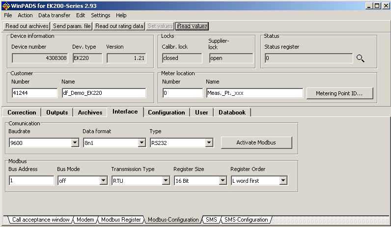
Визуальные стандартные настройки «Modbus» с использованием программы «WinPADS» представлены на рис. 1.
Адреса для создания карт «Modbus»
Протокол «Modbus» позволяет считать и изменить практически любые данные в ЕК280/ЕК290.
Для того, чтобы получить доступ, необходимо создать адрес «Modbus», связать с внутренним адресом Lis200 и определить тип данных. Это может быть сделано с помощью WPP-файла или с использованием программы «WinPADS».
Диапазоны адресов «Modbus» в ЕК280/ЕК290.
Текущие значения переменных LIS200 могут быть считаны по их соответствующим «Modbus» (регистрам) адресам.
Соответствие адресов по умолчанию приводится в документе.
Это означает, что для получения значения можно явно задать адрес «Modbus».
Значения архивов не могут быть считаны таким образом, так как у них нет соответствующих LIS200-адресов. Для чтения архивов был установлен другой механизм.
Этот механизм делит все регистры «Modbus» на несколько диапазонов адресов.
Нижняя часть определяется от адреса 1 до 999 и содержит текущие значения.
Доступ осуществляется, как описано выше.
Диапазон адресов 1000 до 65535 может содержать заархивированные значения из архивов и может быть разделен на все доступные архивы.
В корректорах ЕК280 и ЕК290 используется только диапазон для интервального архива, начиная с «Modbus» адреса 2000.
По умолчанию данный диапазон в корректорах не предусмотрен. Для его использования необходимо провести параметризацию корректора с помощью программ «WinPADS», либо «enSuite», руководствуясь документом.
Диапазон адресов от адреса 1 до 999 частично параметризируется, по умолчанию, на предприятии. Адреса «Modbus» параметров, используемые по умолчанию, формат кода и их соответствие адресам Lis200, приведены в документе.
Главным преимуществом (а так же основным недостатком) «Modbus» является гибкая передача параметров и архивов. Каждое приложение «Modbus» может использовать различные виды формата данных для одних и тех же значений.
Это необходимо учитывать для корректного согласования ведущего и ведомого устройств «Modbus».
Протокол «Modbus» для EK280/290 поддерживает стандартные и специализированные типы данных, описание которых также приводится в документе.
«Modbus» с использованием интерфейсов RS232 и RS485
Через интерфейсы RS232 и RS485 корректоров по протоколу «Modbus» могут осуществляться операции чтения и записи отдельных значений, а также могут быть прочитаны архивы. Для осуществления считывания данных по протоколу «Modbus» с использованием интерфейсов RS232 и RS485, необходимо руководствоваться информацией, приведённой в документах.
Настройка временного окна для запроса данных.
В базовой конфигурации, которая отображается по умолчанию, можно определить пользовательские временные окна, во время которых данные корректора доступны внешним устройствам по интерфейсам. Временные окна 5 и 6 зарезервированы для доступа с прямым соединением RS232.Обычно используется только временное окно 5. Лишние временные окна можно отключить, установив начало и конец временного окна в одно значение.
Для постоянного доступа установите начало окна 5 — «00:00», а конец — «23:59» и запишите изменения в корректор.
Программное обеспечение для работы по «MODBUS» с EK280 и EK290
Для работы по «MODBUS» с EK280 и EK290 необходимо использовать программное обеспечение, поддерживающее протокол «MODBUS», разработанный в соответствии со стандартом фирмы «MODICON, Inc., Industrial Automation Systems».
Рекомендуемое программное обеспечение:
- Simply Modbus Master, Version 8.0.4
- Modbus Poll, Version 3.54;
- ModLink;
- Modscan32.
Далее приводится пример использования программы «Simply Modbus Master» для контроля обмена по протоколу Modbus «Корректоров газа потоковых EK280 и EK290».
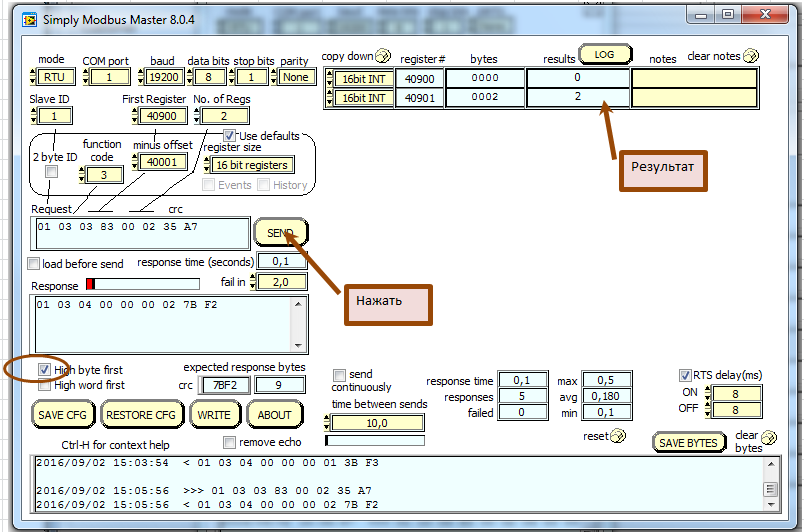
Программа представляет собой удобный визуальный интерфейс для задания параметров обмена и контроля результатов обмена. Пример окна интерфейса представлен на рисунке 2.
Перед сеансом обмена необходимо задать:
- версию протокола Modbus ASCII или RTU;
- номер COM порта;
- скорость обмена;
- формат обмена.
Эти параметры находятся в левом верхнем углу окна программы.
Ниже задаются:
- Адрес Modbus корректора;
- Первый считываемый регистр;
- Количество считываемых регистров.
Ниже задаются настройки пользователя:
- Код функции;
- Тип адресации;
- Размер регистра.
Примечание. Указанные выше параметры подробно описаны в настоящем документе.
Сформированное сообщение отобразится ниже в окне (рис. 2).
Для осуществления чтения необходимо нажать кнопку «SEND» (рис. 2).
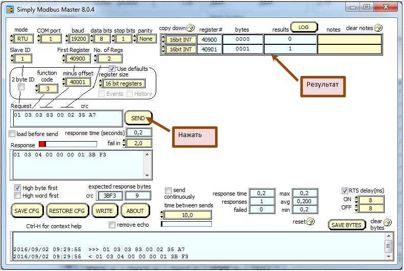
Результат отобразится в правом верхнем углу окна программы в соответствии с заданным форматом Modbus.
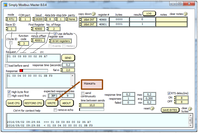
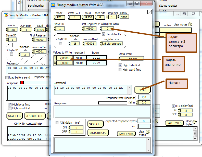
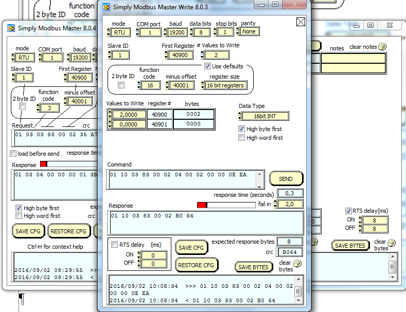
Для осуществления записи необходимо нажать клавишу «Запись» (рис. 3).
Откроется окно, показанное на рисунке 4. Здесь приведён пример записи кода поставщика. В этом окне необходимо задать параметры порта и параметры Modbus.
Корректный ответ устройства представлен на рисунке 5.
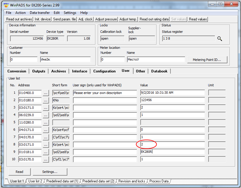
Проверить корректность записанного значения можно с помощью программ «WinPADS» и «enSuite», используя инструмент «Чтение записи отдельных значений» по адресу 3:171 (для кода поставщика). Проверка значения с помощью «WinPADS» представлена рисунке 6.
Проконтролировать правильность записи также можно с помощью программы «Simply Modbus Master», выполнив действия, приведённые в начале приложения. Результат таких действий приведён на рисунке 7.
Литература:
- Modicon Modbus Protocol Reference Guide. PI—MBUS—300 Rev. J.
- IEC 61107:1996 Data exchange for meter reading, tariff and load control. Direct local data exchange (Обмен данными при считывании показаний счетчиков, тарификации и управлении нагрузкой. Прямой локальный обмен данными).
- ГОСТ IEC 61107-2011. Обмен данными при считывании показаний счетчиков, тарификации и управлении нагрузкой. Прямой локальный обмен данными.
- Electricity meters — Part 3: Tariff metering device as additional equipment for electricity meters -EDIS — Energy Data Identification System.
- «Руководство по эксплуатации. Корректор газа потоковый EK290. ЛГТИ.407229.290 РЭ».
- «Руководство по эксплуатации. Корректор газа потоковый EK280. ЛГТИ.407229.280 РЭ».
- «Инструкция по эксплуатации. Корректоры газа потоковые. EK280 ЕК290. ЛГТИ.407229.280 ИЭ».
- «Modbus Communication with Volume Conversion Devices EK220, EK230, EK260, EK280». Elster Instromet.
- «Modbus Обмен данными с приборами EK280 и ЕК290».