-
Contents
-
Table of Contents
-
Bookmarks
Quick Links
with the
EXPLORER
Version 01
20.04.07
www.inmarsat.com/bgan
Whilst the information has been prepared by Inmarsat in good faith, and all reasonable efforts have been made to ensure its accuracy, Inmarsat makes no warranty or
representation as to the accuracy, completeness or fitness for purpose or use of the information. Inmarsat shall not be liable for any loss or damage of any kind, including
indirect or consequential loss, arising from use of the information and all warranties and conditions, whether express or implied by statute, common law or otherwise, are
hereby excluded to the extent permitted by English law. INMARSAT is a trademark of the International Mobile Satellite Organisation, Inmarsat LOGO is a trademark of
Inmarsat (IP) Company Limited. Both trademarks are licensed to Inmarsat Global Limited. © Inmarsat Global Limited 2006. All rights reserved.
BGAN solutions guide
®
700
Summary of Contents for Thrane&Thrane EXPLORER 700
Table of Contents for Inmarsat BGAN Thrane&Thrane Explorer 700:
-
GETTING STARTED EXPLORER 700 TT-99-123227-A · 04.06 OgilvyOne 32526-EXPLORER700-GettingStarted-120×180 06/04/06 12:32 Side 2
-
GETTING STARTED Congratulations on the purchase of your EXPLORER™ 700. Before you start, please check that the following items are present: • EXPLORER™ 700 transceiver with antenna • Two antenna cables for connecting the transceiver with the antenna • Battery • AC/DC adapter • LAN cable • USB cable • Getting Started kit including Quick Guide, electronic manual, etc
-
MAKING A CALL FROM THE EXPLORER™ 700 If you are using a Bluetooth handset, the handset must be paired and placed close to the EXPLORER™ 700. For information on pairing, see the section BLUETOOTH PAIRING at the end of this document. To make a call from a phone connected to the EXPLORER™ 700, dial 00 <country code> <phone number> followed by # or off-hook key. Example: To call Thrane & Thrane in Denmark: (+45 39 558800), dial 00 45 39 558800 followed by # or off-hook key. NOTE: There are two audio qualities: Standar
-
a. Using the built-in compass of the EXPLORER™ 700 antenna as reference, rotate and tilt the antenna so that it points in the approximate direction of the BGAN satellite. b. Use the displayed signal strength and the pointing sound to find the highest possible signal strength, while slowly rotating and tilting the EXPLORER™ 700. c. Press OK when you have obtained the highest possible signal strength. The EXPLORER™ 700 now starts to establish a connection to the BGAN network. The display shows th
-
32526-EXPLORER700-GettingStarted-120×180 06/04/06 12:33 Side 3
-
create a dedicated dial-up connection. In Windows XP, a dial-up connection is created as follows: a. Select Connect To from the Start menu. b. Select Show All Connections and open the New Connection Wizard. c. Go through the Wizard. d. If you are asked for a modem, select your installed ISDN modem from the list. e. Type in the phone number and password provided from your Internet Service Provider. f. When you have finished, close the New Connection Wizard. 4. To connect to the Internet or to
-
TT-99-123227-A · 04.06 OgilvyOne Thrane & Thrane A/S • [email protected] • www.thrane.com 32526-EXPLORER700-GettingStarted-120×180 06/04/06 12:32 Side 1
-
2. Place your Bluetooth device close to the EXPLORER™ 700. 3. On your Bluetooth device, search for new devices and select the EXPLORER™ 700 when it is found. The default Bluetooth name of the EXPLORER™ 700 is EXPLORER 700. 4. If there is more than one EXPLORER™ 700 in the list, you can use the MAC address to locate the correct one. To see the MAC address of your EXPLORER™ 700, enter the display menu system and select PROPERTIES > TERMINAL > HARDWARE > MAC ADDRESS. 5. On your Blue
-
MAKING A LAN CONNECTION To make a LAN connection, simply connect the LAN cable between your computer and one of the LAN connectors on the EXPLORER™ 700, and start up the EXPLORER™ 700 as described in the beginning of this document. As soon as the display of the EXPLORER™ 700 shows READY, the connection is established automatically. You are now ready to browse the Internet, check e-mails, send files etc. NOTE: For information on configuration, refer to the User Manual. SETTING
-
Connect the cables Connect the cable(s), including the antenna cable, to the relevant connector(s) on the EXPLORER™ 700. The connector panel is located on the side of the EXPLORER™ 700. The antenna connector is located on the opposite side of the EXPLORER™ 700. Switch on the EXPLORER™ 700 Push the power button next to the display and hold it for a second until the green power indicator lights up. Enter the SIM PIN a) When you are asked for a P
-
MAKING A USB CONNECTION To make a USB connection, do as follows: 1. Connect the USB cable between your computer and the EXPLORER™ 700. Note that the connector on the EXPLORER™ 700 is a USB Type B connector. 2. Start up the EXPLORER™ 700 as described in the beginning of this document. 3. If it is the first time you connect to the terminal using USB, insert the Thrane & Thrane CD ROM provided with your EXPLORER™ 700 and install the EXPLORER™ 700 USB driver. Then create a dial-up connection. In Windows XP, a dial-up connection is
-
32526-EXPLORER700-GettingStarted-120×180 06/04/06 12:35 Side 12
Questions, Opinions and Exploitation Impressions:
You can ask a question, express your opinion or share our experience of Inmarsat BGAN Thrane&Thrane Explorer 700 device using right now.
Inmarsat BGAN Thrane&Thrane Explorer 700: Available Instructions
Note for Owners:
Guidesimo.com webproject is not a service center of Inmarsat trademark and does not carries out works for diagnosis and repair of faulty Inmarsat BGAN Thrane&Thrane Explorer 700 equipment. For quality services, please contact an official service center of Inmarsat company. On our website you can read and download documentation for your Inmarsat BGAN Thrane&Thrane Explorer 700 device for free and familiarize yourself with the technical specifications of device.
-
Corsair Carbide series
CARBIDE SERIES®INSTALLATION GUIDE n GUIDE D’INSTALLATIONINSTALLATIONSANLEITUNG n INSTALLATIEHANDLEIDINGGUIDA ALL’INSTALLAZIONE n Guía de instalación GUIA DE INSTALAÇÃO n PRZEWODNIK PO INSTALACJI安裝指南 n インストールガイド47100 Bayside Parkway • Fremont • California • 94538 • USA | corsair.com© 2015-2020 CORSAIR MEMORY, Inc.All rights reserved. CORSAIR, the sails lo …
Carbide series Enclosure, 64
-
LabJack U12
LabJack U12 Quickstart Guide Revision 1.09 9/8/2003 LabJack Corporation www.labjack.com [email protected] For the complete LabJack U12 User’s Guide or the latest version of the LabJack software, go to www.labjack.com. The LabJack U12 is a measurement and automation peripheral that enables the connection of a PC to the real world. Although the LabJack U12 has many redundant protection m …
U12 Data Loggers, 6
-
Trust 3010A
3010A WIRELESS DESKSET 1 UK Product information Mouse Receiver A: Left button B: Right button C: Intelli-wheel Battery-low LED (red lit) D: Connect button E: Motion sensor F: Battery compartment G: Connect button H: Battery compartment I: Standby button J: Browser buttons K: Open default homepage L: Open default email program M: Open My Computer N: Open calculator O: Open media p …
3010A Computer Accessories, 5
-
HP D5062
(15-inch Viewable Image)Important Safety InstructionsWhat Your New Monitor OffersUnpacking Your MonitorSetting Up Your MonitorHow To Install The DriversAdjusting Your MonitorUsing Your MonitorTroubleshootingTechnical SpecificationsCare and CleaningEnvironmental InformationHardware WarrantySoftware WarrantyRegulatory Informationwww.hp.com/go/ …
D5062 Monitor, 40
-
StarTech.com STNDTBLT1A5T
Manual Revision: 08/19/2015For the latest information, technical specications, and support for this product, please visit www.startech.com/STNDTBLT1A5T.DE: Bedienungsanleitung — de.startech.comFR: Guide de l’utilisateur — fr.startech.comES: Guía del usuario — es.startech.comIT: Guida per l’uso — it.startech.comNL: Gebruiksaanwijzing — nl.startech.comPT: Guia do usuário — pt.startech …
STNDTBLT1A5T Computer Accessories, 12
-
Network Technologies XTENDEX ST-C5VA-WL500
Man073 Rev 1/24/06 ST-C5VA-WL500 WALL MOUNT VGA VIDEO AND STEREO AUDIO EXTENDER Installation and Operation Manual XTENDEXTM Series NETWORKTECHNOLOGIESINCORPORATEDTel:330-562-7070Fax:330-562-19991275 Danner DrAurora, OH 44202 www.networktechinc.comNTIR …
XTENDEX ST-C5VA-WL500 Computer Accessories, 14
-
Logitech Harmony One
Logitech®Harmony® OneAdvanced Universal RemoteTouch-screen simplicityAdvanced remote control with full-colour touch screen for your homeentertainment system• Full-colour touch screen provides easy, one-touch access to activities• Sculpted backlit buttons allow you to navigate easily – even in the dark• Replaces up to 15 remotes, reducing clutter and complexity in the living room• The e …
Harmony One Remote Control, 2
-
Sony VGP-UPR1A
4-173-025-11 (1)EnglishTo customers installing the softwareFrançaisPour les utilisateurs qui installent le logicielDeutschFür Kunden, die die Software installierenItalianoInstallazione del software da parte dei clientiNederlandsVoor klanten die de software installerenEspañolPara los clientes que van a instalar el softwareSuomiOhjelman asentaville asiakkailleΕλληνικάΓια πελάτες …
VGP-UPR1A Computer Accessories, 178
-
Icom BC-146
ICOMBATTERYCHARGERBC-146INSTRUCTIONSCAUTION•AUSEINDOORSONLY!NEVERexpose the chargerto rain,snoworanyliquids.•NEVERlet metal, wire, etc. touchanyinternal part ofthecharger.•NEVER incinerate used batteries. This maycauseanexplosion.•NEVER usethechargerwhen it is covered by objectswhichimpedeheatdispersal.•Placethechargerin asecureplaceto avoidinadvertentusebychildren.•AVOID charging in e …
BC-146 Battery Charger, 2
Popular Computer Accessories User Guides:

USER MANUAL
EXPLORER 700
Thrane & Thrane A/S • info@thrane.com • www.thrane.com

98-122988-DraftB6 ii
TT—3720A EXPLORER™ 700
Document number: 98-122988-DraftB6
Release date: 26 April 2006
Information in this document is subject to change without notice and does not represent a commitment on
the part of Thrane & Thrane A/S.
Copyright
© 2006 Thrane & Thrane A/S. All rights reserved.
Trademark Acknowledgements
•EXPLORER is a trademark of Thrane & Thrane A/S.
•Bluetooth is a registered trademark of Bluetooth SIG.
•Windows and Outlook are registered trademarks of Microsoft Corporation in the United States and other
countries.
•Inmarsat is a registered trademark of the International Maritime Satellite Organisation (IMSO) and is
licensed by IMSO to Inmarsat Limited and Inmarsat Ventures plc.
• Inmarsat’s product names are either trademarks or registered trademarks of Inmarsat.
• Other product and company names mentioned in this manual may be trademarks or trade names of their
respective owners.
Company Addresses
www.thrane.com
Denmark Denmark
Thrane & Thrane A/S
Lundtoftegårdsvej 93 D
DK—2800 Kgs. Lyngby
Denmark
T: +45 39 55 88 00
F: +45 39 55 88 88
Thrane & Thrane Aalborg A/S
Porsvej 2
DK-9200 Aalborg SV
Denmark
T: +45 39 55 88 00
F: +45 96 34 61 01
USA China
Thrane & Thrane, Inc.
509 Viking Drive, Suites K, L and M
Virginia Beach, VA 23452
USA
T: +1(866) SATCOMS or
+1 (757) 463-9557
F: +1 (757) 463-9581
Thrane & Thrane Shanghai
Representative Office
28J Pufa Tower
588 Pudong Rd(S), Pu Dong
200120 Shanghai
P. R. China
T: +86 21 68 87 87 80
F: +86 21 68 87 71 12

98-122988-DraftB6 iii
Safety Summary 1
The following general safety precautions must be observed during all phases of
operation, service and repair of this equipment.
Failure to comply with these precautions or with specific warnings elsewhere in this
manual violates safety standards of design, manufacture and intended use of the
equipment. Thrane & Thrane A/S assume no liability for the customer’s failure to
comply with these requirements.
Do Not Operate in an Explosive Atmosphere
Do not operate the equipment in the presence of flammable gases or fumes.
Operation of any electrical equipment in such an environment constitutes a
definite safety hazard.
Keep Away from Live Circuits
Operating personnel must not remove equipment covers. Component
replacement and internal adjustment must be made by qualified maintenance
personnel. Do not replace components with the power cable connected. Under
certain conditions, dangerous voltages may exist even with the power cable
removed. To avoid injuries, always disconnect power and discharge circuits
before touching them.
Do Not Service Alone
Do not attempt internal service or adjustments unless another person, capable of
rendering first aid resuscitation, is present.
Do Not Substitute Parts or Modify Equipment
Because of the danger of introducing additional hazards, do not substitute parts
or perform any unauthorized modification to the equipment.
Keep Away from Antenna Front
This device emits radio frequency energy when switched
on. To avoid injury, keep a minimum safety distance of 1
m from the antenna front when the EXPLORER™ 700 is
on. See also the following section FCC Caution.
Only Use Approved Batteries from Thrane & Thrane
Use of non approved batteries may result in explosion, fire, electrical shock or
injury.
Observe Marked Areas
Under extreme heat conditions do not touch areas of the
EXPLORER™ 700 that are marked with this symbol, as it
may result in injury.

Antenna Safety Instructions
98-122988-DraftB6 iv
FCC Caution
Operation of the WLAN within the 5745~5825MHz frequency range is restricted to indoor environments.
FCC Radiation Exposure statement
Transceiver Unit (when separated from the Antenna Unit):
This equipment complies with FCC radiation exposure limits for an uncontrolled environment. This equipment
should be installed and operated at a distance greater than 20 centimetres (8 inches) between the
Transceiver Unit, yourself or any bystander to comply with the Radiation Exposure Requirements.
Antenna Safety Instructions 2
Use Only Manufacturer Supplied Antennas
Antenna Minimum Safe Distance: 1 m
Antenna Gain
Directional, with maximum gain of 14.9 dB reference to isotropic.
The Federal Communications Commission has adopted a safety standard for human exposure to RF (Radio
Frequency) energy which is below the OSHA (Occupational Safety and Health Act) limits.
Antenna Mounting
The antenna supplied by the manufacturer must be located such that during radio transmission, no person or
persons can come closer than the above indicated minimum safe distance to the antenna, i.e. 1 m.
To comply with current FCC RF Exposure limits, the antenna must be installed at or exceeding the minimum
safe distance shown above, and in accordance with the requirements of the antenna manufacturer or
supplier.
Antenna Substitution
Do not substitute any antenna for the models supplied or recommended by the manufacturer. You may be
exposing people to excess radio frequency radiation. You may contact the manufacturer for further
instructions.
Radiation Warning
You, as the qualified end-user of this radio device, must control the exposure conditions of bystanders to
ensure the minimum separation distance (above) is maintained between the antenna and nearby persons,
for satisfying RF Exposure compliance. The operation of this transmitter must satisfy the requirements of
Occupational/Controlled Exposure Environment, for work-related use. Only use the terminal when persons
are at least the minimum distance from the front face of the antenna.
WARNING! Maintain a separation distance of at least 1 m from the front face of the antenna
to a person.

About the Manual
98-122988-DraftB6 v
About the Manual 3
Intended Readers
This manual is a user manual for the EXPLORER™ 700. The readers of the manual include anyone who is
using or intends to use the EXPLORER™ 700. No specific skills are required to operate the EXPLORER™ 700.
However, it is important that you observe all safety requirements listed in the beginning of this manual, and
operate the EXPLORER™ 700 according to the guidelines in this manual.
Manual Overview
This manual has the following chapters:
•Introduction contains an overview of the BGAN services and a brief description of the system.
•Getting started explains how to insert SIM card and battery, start up the unit, and navigate the display
menus. It also contains a short guide to making the first call.
•Using the display and keypad contains an overview of the display menu system and explains how to use
the menus.
•Using the interfaces explains how to set up and use each interface.
•Using the web interface explains how to use the built-in web interface of the EXPLORER™ 700, and
describes the available menus and settings. It also explains advanced setup of interfaces with the web
interface.
•Maintenance and troubleshooting contains a short troubleshooting guide and explains how to update
software. It also describes and lists the alarm messages that may appear in the handset, and gives
information on where to get further help if necessary.
Typography
In this manual, typography is used as indicated below:
Bold is used for the following purposes:
• To emphasize words.
Example: “Do not touch the antenna front during pointing”.
• To indicate what the user should select in the user interface.
Example: “Select Settings > Interfaces > Bluetooth and click Enabled”.
• To emphasize the paragraph title in cross-references.
Example: “For further information, see Connecting Cables on page…”.
COURIER (with capital letters) is used for the following purposes:
• To indicate text appearing in the display.
Example: “the Main screen shows READY”.
• To indicate low level commands such as AT commands.
Example: “In your terminal program, type ATD”.

98-122988-DraftB6 vi
Table of Contents
Safety Summary ………………………………………………………………………………….iii
Antenna Safety Instructions ………………………………………………………………….. iv
About the Manual ………………………………………………………………………………… v
Chapter 1 Introduction
Welcome …………….……………………………………………………………………………….1
In this chapter ……………………………………………………………………………………..2
The BGAN system ………………………………………………………………………………… 3
The BGAN services ………………………………………………………………………………..5
Features and interfaces of the EXPLORER™ 700 …………………………………………6
Your EXPLORER™ 700 terminal ……………………………………………………………….8
Matrix of services and communication interfaces ……………………………………… 11
What’s next? ………………………………………………………………………………………. 11
Chapter 2 Getting started
In this chapter …………………………………………………………………………………….12
Unpacking and assembling ……………………………………………………………………12
Connecting cables ……………………………………………………………………………….18
Powering the EXPLORER™ 700 …………………………………………………………….. 20
Options for the start-up procedure ………………………………………………………….21
Entering the SIM PIN ………………………………………………………………………….. 23
Pointing the antenna ………………………………………………………………………….. 24
Making the first call ……………………………………………………………………………. 28
Making the first data connection (LAN) ………………………………………………….. 30
What’s next? ……………………………………………………………………………………….31
Chapter 3 Using the display and keypad
In this chapter …………………………………………………………………………………… 32
Menu overview ………………………………………………………………………………….. 32
Display during start-up ……………………………………………………………………….. 34
Display symbols …………………………………………………………………………………. 35
Navigating the display and keypad ……………………………………………………….. 36
The menus ………………………………………………………………………………………… 37
Messages menu …………………………………………………………………………………. 37

Table of Contents
98-122988-DraftB6 vii
Connect menu …………………………………………………………………………………… 38
Calls menu ………………………………………………………………………………………… 38
Settings menu …………………………………………………………………………………… 39
Properties menu ………………………………………………………………………………… 42
Help desk …………………………………………………………………………………………. 44
Dynamic information in the display ……………………………………………………….. 45
What’s next? ……………………………………………………………………………………… 46
Chapter 4 Using the interfaces
In this chapter …………………………………………………………………………………. 47
General ……………………………………………………………………………………………. 47
Tools for setup and use ……………………………………………………………………….. 47
Services and interfaces ……………………………………………………………………….. 48
Enabling or disabling an interface ………………………………………………………… 49
Bluetooth pairing ……………………………………………………………………………..50
What is pairing? …………………………………………………………………………………50
Pairing devices in which you can enter a passkey …………………………………….50
Using a phone or fax machine …………………………………………………………….51
Selecting the call type …………………………………………………………………………..51
Connecting an analog phone or a fax machine ……………………………………….. 53
Connecting an ISDN phone or a G4 fax machine ……………………………………… 54
Connecting a Bluetooth handset …………………………………………………………… 55
Entering the SIM PIN using a phone ……………………………………………………… 56
Making or receiving a phone call with the EXPLORER™ 700 ……………………… 57
Making a call to the EXPLORER™ 700 ……………………………………………………. 58
Dialing functions ………………………………………………………………………………..58
Sending or receiving a fax message ………………………………………………………. 63
Using a computer …………………………………………………………………………….. 64
Choosing an interface for data connection ……………………………………………… 64
Standard or Streaming data …………………………………………………………………. 65
Using the LAN interface ……………………………………………………………………….66
Using the WLAN interface …………………………………………………………………….68
Using the USB interface ………………………………………………………………………. 69
Using a computer with ISDN ………………………………………………………………… 72
Using a computer with Bluetooth ………………………………………………………….. 73
Creating a dial-up connection ………………………………………………………………. 74

Table of Contents
98-122988-DraftB6 viii
Additional interfaces ………………………………………………………………………… 76
Using the EXPLORER™ 700 antenna ……………………………………………………… 76
Using a solar panel …………………………………………………………………………….. 77
Using the I/O interface ………………………………………………………………………… 78
Using the EXPLORER™ Bluetooth Handset charger ………………………………….. 79
What’s next? ……………………………………………………………………………………. 79
Chapter 5 Using the web interface
In this chapter ………………………………………………………………………………….80
Introduction ……………………………………………………………………………………..80
The web interface ……………………………………………………………………………….80
Accessing and navigating the web interface …………………………………………… 82
Entering the SIM PIN in the web interface ………………………………………………85
The Home window ……………………………………………………………………………86
Overview ……………………………………………………………………………………………86
Terminal properties ……………………………………………………………………………. 87
Managing calls and data sessions ………………………………………………………… 87
Pointing using web interface ………………………………………………………………..88
Using the phone book ……………………………………………………………………….89
General usage ……………………………………………………………………………………89
Editing phone book entries …………………………………………………………………..90
Using the Call log ………………………………………………………………………………91
Information on total usage ……………………………………………………………………91
Exporting the call log ……………………………………………………………………………91
Viewing the lists of calls ……………………………………………………………………… 92
Handling messages ………………………………………………………………………….. 93
Sending an SMS message from the EXPLORER™ 700 ……………………………….. 93
Options for messages in the Outbox ………………………………………………………. 94
Options for messages in the Sent folder …………………………………………………. 94
Sending an SMS message to the EXPLORER™ 700 …………………………………… 95
Receiving a message …………………………………………………………………………..95
Options for new SMS messages ……………………………………………………………. 96
Options for SMS messages in the Inbox …………………………………………………. 96
Configuring message settings ………………………………………………………………. 97
Setting up the EXPLORER™ 700 …………………………………………………………99
Accessing the EXPLORER™ 700 settings …………………………………………………. 99

Table of Contents
98-122988-DraftB6 ix
Power up behavior ……………………………………………………………………………… 99
Setting the display backlight and contrast ………………………………………………100
Turning audio indicators on or off ………………………………………………………..100
Enabling activation of stealth mode ……………………………………………………… 101
Setting up the interfaces …………………………………………………………………..102
Enabling/disabling interfaces ………………………………………………………………102
Description of data settings ………………………………………………………………….103
Configuring the USB interface ………………………………………………………………105
Configuring the LAN interface ………………………………………………………………107
Configuring the WLAN interface …………………………………………………………… 110
Configuring the Bluetooth interface ……………………………………………………….113
Pairing Bluetooth devices from the web interface …………………………………….115
Configuring the Phone/Fax settings ……………………………………………………….118
Configuring the ISDN interface ……………………………………………………………..119
Setting a common APN ……………………………………………………………………….120
Properties, software upload and alarm list ………………………………………..121
Viewing the properties of the EXPLORER™ 700 ………………………………………..121
Uploading software …………………………………………………………………………… 122
Viewing the Alarm List ……………………………………………………………………….. 123
Administration …………………………………………………………………………………124
Accessing the administration settings …………………………………………………… 124
Using Profiles …………………………………………………………………………………… 127
Using a Traffic Flow Template ………………………………………………………………130
Help desk and diagnostic report ……………………………………………………….132
Accessing the Help desk …………………………………………………………………….. 132
Generating a diagnostic report ……………………………………………………………. 132
What’s next? ……………………………………………………………………………………132
Chapter 6 Maintenance and troubleshooting
In this chapter ………………………………………………………………………………….. 133
Getting support …………………………………………………………………………………. 133
Uploading software ……………………………………………………………………………134
Maintenance ……………………………………………………………………………………. 134
Options and accessories ……………………………………………………………………..136
Troubleshooting guide ……………………………………………………………………….. 137
Status signaling …………………………………………………………………………………146

Table of Contents
98-122988-DraftB6 x
Alarm messages ………………………………………………………………………………..146
Log files ……………………………………………………………………………………………152
Appendix A Technical specifications
In this appendix …………………………………………………………………………………153
General specifications …………………………………………………………………………153
Battery ……………………………………………………………………………………………..154
Power input ………………………………………………………………………………………155
SIM interface …………………………………………………………………………………….155
Phone interface, 2-port ……………………………………………………………………….156
ISDN interface, 2-port ………………………………………………………………………… 157
LAN interface, 2-port ………………………………………………………………………….158
USB interface …………………………………………………………………………………….159
WLAN Access Point …………………………………………………………………………….160
Bluetooth interface ……………………………………………………………………………..161
Antenna interface on Transceiver …………………………………………………………162
Detachable antenna ……………………………………………………………………………163
EXPLORER™ Bluetooth Handset charger interface …………………………………..164
Solar panel interface ………………………………………………………………………….165
I/O interface ………………………………………………………………………………………165
Serial number labels …………………………………………………………………………..166
Conformity …………..…………………………………………………………………………… 167
Appendix B AT commands
In this appendix …………………………………………………………………………………169
Starting up an AT command session ……………………………………………………..169
List of supported AT commands …………………………………………………………… 170
Glossary ………………………………………………………………………………………………………… 176
Index …………………………………………………………………………………………………………180
98-122988-DraftB6 1
Chapter 1
Introduction 1
Welcome
Congratulations on the purchase of your EXPLORER™ 700!
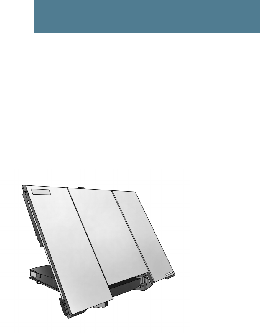
The EXPLORER™ 700 is a broadband mobile terminal with a detachable antenna, providing high-
speed data and voice communication via satellite through the Broadband Global Area Network
(BGAN).
Just plug in a phone, fax, laptop or PDA, or use the Bluetooth® or WLAN interface, point the
antenna towards the BGAN satellite — and you are online.
EXPLORER™ 700 is an essential evolution in satellite communication for governments,
broadcasters and other organizations dependent on relaying information fast under any condition.
The EXPLORER™ 700 provides access to the highest bandwidth available on the BGAN network –
up to 492 kbps. The system offers multi-user as well as single-user functionality, making it a
flexible solution for a variety of applications.

Chapter 1: Introduction
98-122988-DraftB6 2
Applications include:
• Internet browsing
• Phone and fax services
• Large file transfers
• Video conferencing and Streaming
• VPN (Virtual Private Network) access to corporate servers
In this chapter
This chapter gives an overview of the BGAN system and services, and introduces the
EXPLORER™ 700.
It also gives an overview of the physical unit and its features and functions.
Chapter 1: Introduction
98-122988-DraftB6 3
The BGAN system
What is BGAN?
The Broadband Global Area Network (BGAN) is a mobile satellite service that offers high-speed
data up to 492 kbps and voice telephony. BGAN enables users to access e-mail, corporate
networks and the Internet, transfer files and make telephone calls.
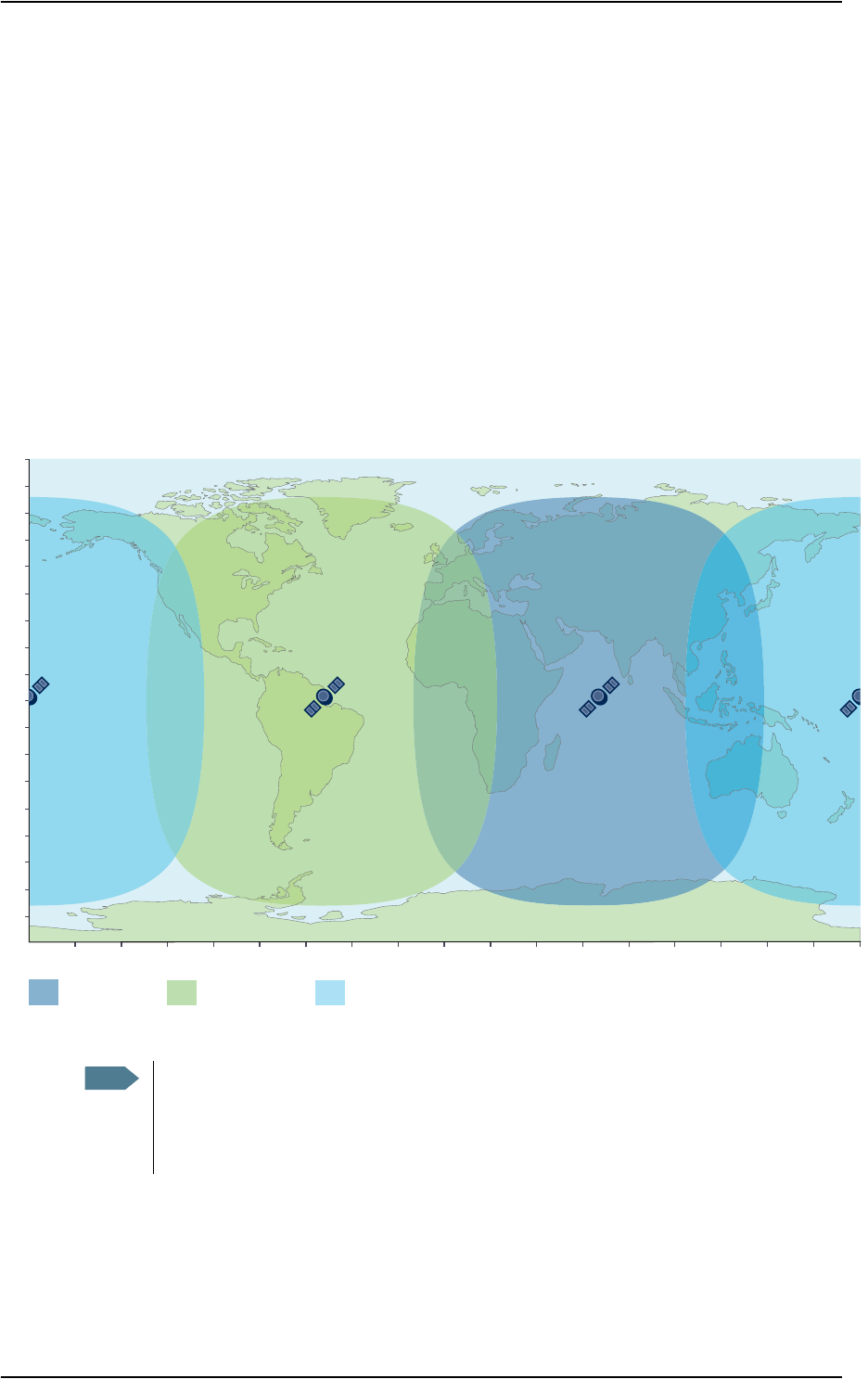
Coverage
The Inmarsat® BGAN services are based on geostationary satellites situated above the equator.
Each satellite covers a certain area (footprint). The coverage map below shows the footprints of the
BGAN system.
&SATELLITE
0LANNEDBYMID
&SATELLITE
4OBEDEFINED
WWWINMARSATCOM
&SATELLITE 4HEMAPDEPICTS)NMARSATgSEXPECTATIONSOFCOVERAGEBUTDOESNOT
REPRESENTAGUARANTEEOFSERVICE4HEAVAILABILITYOFSERVICEATTHE
EDGEOFCOVERAGEAREASFLUCTUATESDEPENDINGONVARIOUSCONDITIONS
%
)/2
7
!/27
%
0/2
%
0/2
(ocean region POR)
(ocean region AOR-W)(ocean region IOR)
Note The map depicts Inmarsat’s expectations of coverage, but does not represent a
guarantee of service. The availability of service at the edge of coverage areas fluctuates
depending on various conditions.
The launch of the F-3 satellite will be determined in due course.
Chapter 1: Introduction
98-122988-DraftB6 4
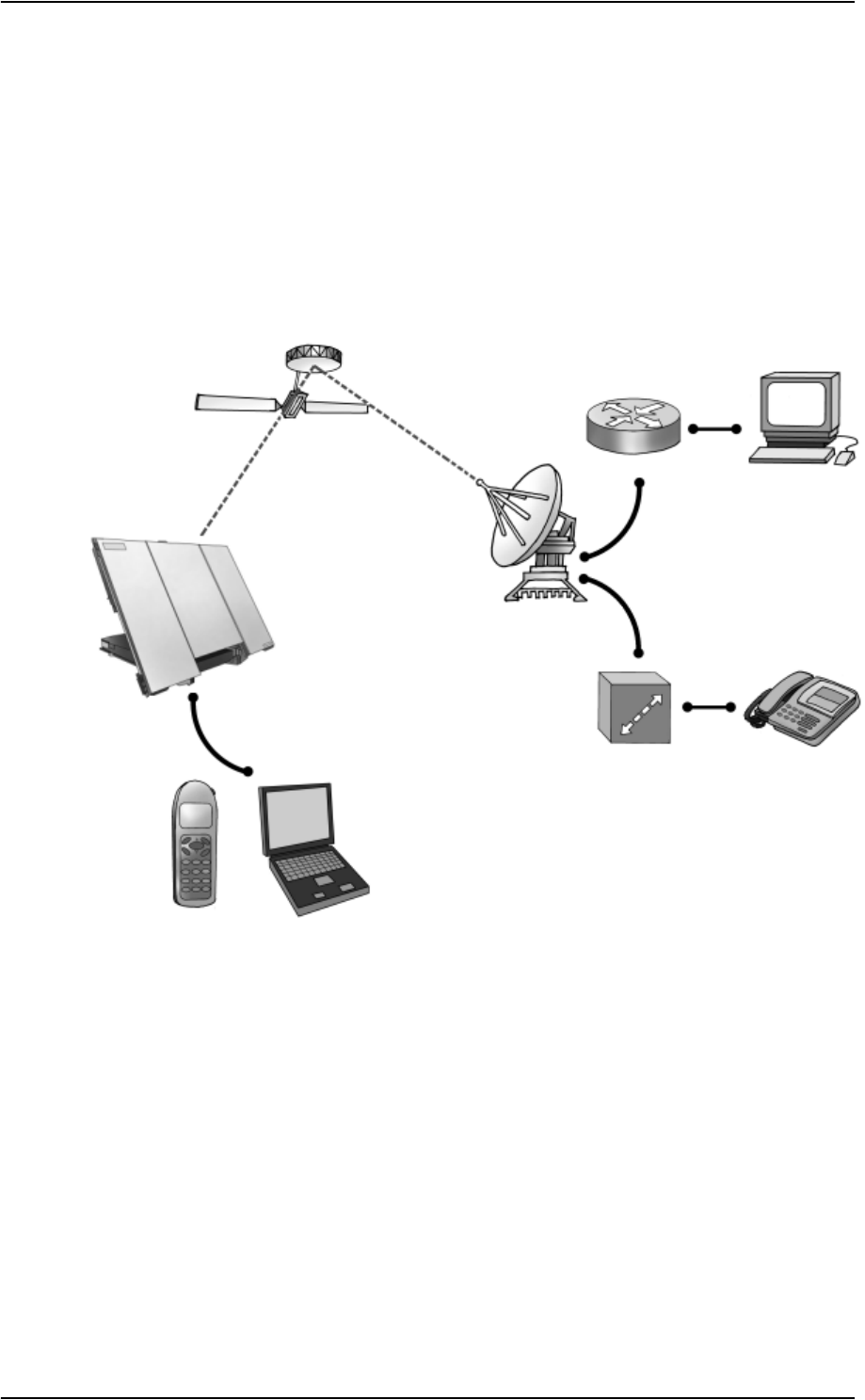
Overview of the BGAN system
A complete BGAN system includes the EXPLORER™ 700 with connected peripherals, the BGAN
satellite, and the Satellite Access Station (SAS). The satellites are the connection between your
EXPLORER™ 700 and the SAS, which is the gateway to the worldwide networks (Internet,
telephone network, cellular network, etc.).
Satellite IP Router
PC
Satellite Access Station
(SAS)
Switch Voice and ISDN
Laptop
Bluetooth
Handset
Circuit Switched Network
Packet Switched Network
EXPLORER™ 700

Chapter 1: Introduction
98-122988-DraftB6 5
The BGAN services
Supported services
The services currently supported by BGAN comprise:
• A Packet Switched connection to the Internet
• A Circuit Switched (Dialed) connection for voice, fax or data
• Short Messaging Service (SMS)
Packet data service
The BGAN network supports different classes of data connection to the Internet.
• Using a Standard data connection, several users can share the data connection
simultaneously. This type of connection is ideal for e-mail, file transfer, and Internet and
intranet access. The user pays for the amount of data sent and received.
• Using a Streaming data connection, you get an exclusive, high-priority connection, ensuring
seamless transfer of data. This type of connection is ideal for time critical applications like live
video over IP. The user pays for the duration of the connection (per minute charge).
Circuit switched (dialed) service
Three types of circuit switched connection are available:
•Standard Voice. A low-tariff connection for voice only. The voice signal is compressed to
4.0 kbps, which reduces the bandwidth use and consequently the tariff.
•3.1 kHz Audio. A high quality connection which can be used for Premium Voice, G3 fax or
analog modem.
The signal is uncompressed 3.1 kHz audio, which allows for optimum voice quality.
•ISDN. A 64 kbps connection used for ISDN speech, G4 fax or 64 kbps UDI/RDI data.
SMS service
The BGAN system provides a Short Messaging Service (SMS) for sending and receiving SMS
messages.
Supplementary services
The BGAN system also provides the following supplementary services:
• Call hold
• Call waiting
•Call forwarding
•Voice mail
• Call barring (using AT commands)

Chapter 1: Introduction
98-122988-DraftB6 6
Features and interfaces of the EXPLORER™ 700
Features
Simultaneous voice and data communication over BGAN
Full duplex, single or multi-user, up to 492 kbps
Support for streaming IP at 32, 64, 128, 256 kbps
Seamless global coverage
Standard LAN, WLAN, USB, ISDN, Bluetooth and Phone/Fax ports
Integral DHCP/NAT wireless router
Built-in web interface allowing you to manage your phone book, messages and calls, and
customize the terminal to your specific needs
10-32 V DC input
100-240 V AC power adapter
Solar panel direct interface
Detachable lightweight antenna with integral transceiver stand and transceiver-to-antenna
range up to 100 m/328 ft
Compact portable unit, sturdy and reliable construction
Humidity, dust, weather and temperature-resistant design
Rapid deployment and take-down
CE, FCC and GMPCS certified
Chapter 1: Introduction
98-122988-DraftB6 7
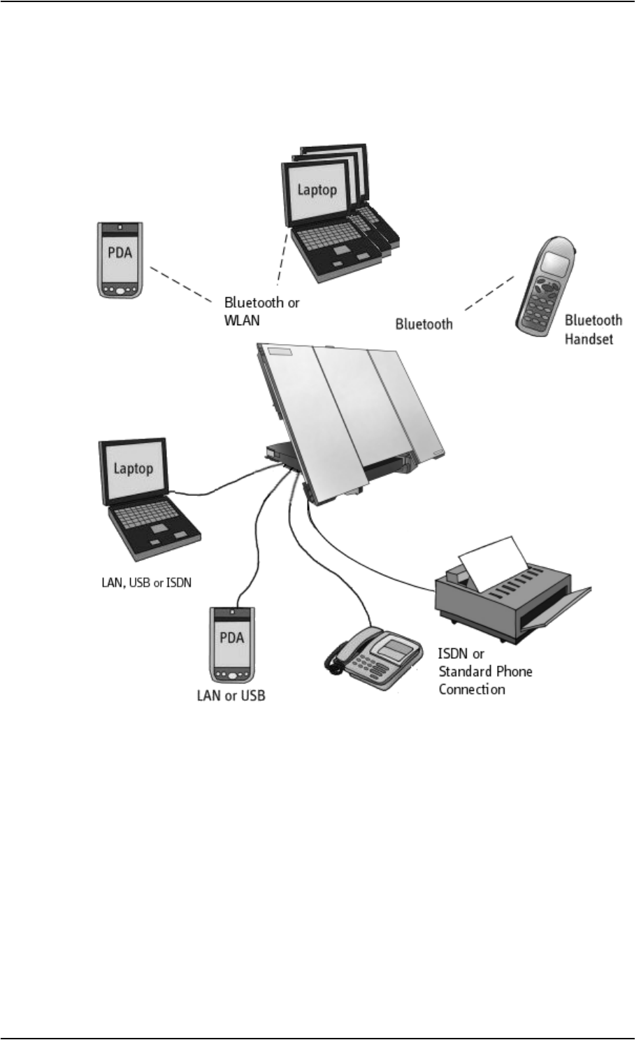
Overview of interfaces
The EXPLORER™ 700 provides a number of interfaces for connection of various types of
computers, fax devices and phones.
Using the interfaces on page 47 describes how to use each of the available interfaces.
Minimizing power consumption
The EXPLORER™ 700 is designed for minimum power consumption. This means that functions that
are not currently used will automatically go into a “sleep mode” to minimize the power
consumption.
In addition to this automatic sleep mode function, you can disable each of the interfaces if they are
not currently used. Note, however, that you will not be able to use these interfaces until you
enable them again. For information on how to enable/disable interfaces, see Enabling or disabling
an interface on page 49.
Chapter 1: Introduction
98-122988-DraftB6 8
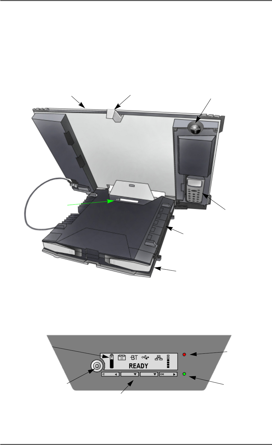
Your EXPLORER™ 700 terminal
Overview
The EXPLORER™ 700 is a compact unit comprising a transceiver with a detachable antenna,
compass, display and keypad, all in one unit.
Display and keypad
The EXPLORER™ 700 has a display and a keypad for displaying status and for changing simple
parameters.
For information on how to use the keypad and display, and for an overview of the display menu
system, see Using the display and keypad on page 32.
Display and
EXPLORER™
Bluetooth Handset
Compass
BGAN Antenna
Keypad
Connector Panel
Battery
Transport Lock
Power indicator
Power Button
Keypad
Display Message indicator

Chapter 1: Introduction
98-122988-DraftB6 9
Light indicators
The EXPLORER™ 700 has two light indicators next to the display: a green power indicator and a
red message indicator.
Green Power indicator
The function of the green Power indicator at the bottom is as follows:
Red Message indicator
The function of the red Message indicator at the top is as follows:
Behavior of green indicator Meaning
Short flash every 2 seconds The EXPLORER™ 700 is on.
Steady light The battery is charging.
Flashing rapidly A charging error has occurred.
For further information, refer to the Troubleshooting Guide on
page 137.
Off No power or Stealth mode.
Behavior of red indicator Meaning
Flashing An alarm is active or
An SMS message has arrived.
Press OK on the keypad to view the alarm(s) or SMS
message(s).a
The red light will keep flashing after OK is pressed if
• there are more SMS messages, or
• an alarm is still active.
For information on alarm messages, see Alarm messages
on page 146.
a. If a computer is connected, you can also view alarms and SMS messages in the built-in web in-
terface in the EXPLORER™ 700. For further information, see Icons in the icon bar on page 83.
Off No messages are present, or the EXPLORER™ 700 is in Stealth
mode.

Chapter 1: Introduction
98-122988-DraftB6 10
User interfaces
The keypad and display are used for pointing the antenna, for displaying status and for changing
simple parameters.
To obtain full access to all features and for ease-of-use, you should use a computer
(a PC, Laptop or similar) and one of the following:
•The web interface. A built-in web interface for easy configuration and daily use. The web
interface is accessed from a computer connected to the EXPLORER™ 700, using an Internet
browser. For further information, see Chapter 5, Using the web interface.
•The BGAN LaunchPad from Inmarsat. BGAN LaunchPad is a computer application used to
control terminals in the BGAN system. LaunchPad is provided on the Inmarsat BGAN CD-ROM
supplied with your EXPLORER™ 700. For information on how to use the LaunchPad, refer to
the manual on the Inmarsat CD-ROM.
Additionally, it is possible to control the EXPLORER™ 700 using AT Commands. Refer to
Appendix B, AT commands.
Antenna
The white part of the EXPLORER™ 700, including the support bracket, is the detachable antenna
module. The antenna module comprises a GPS (Global Positioning System) antenna and a BGAN
antenna. Bluetooth and Wireless LAN antennas are integrated in the transceiver unit.
Compass
The EXPLORER™ 700 also provides a compass to help positioning the
antenna. For further information on how to use the compass, see
Pointing the antenna on page 24.
Battery
The EXPLORER™ 700 comes with a rechargeable battery, which is easily inserted. The battery is
automatically recharged when power is applied to the EXPLORER™ 700. Steady green light
indicates that the battery is charging.
SIM card
The EXPLORER™ 700 has two SIM slots, USIM #1 and USIM #2, located behind the battery. Only
USIM #1 is currently in use. USIM #2 is reserved for future use.
The SIM (Subscriber Identity Module) card used for the EXPLORER™ 700 is a standard SIM card,
which is acquired from the Airtime Provider.
The EXPLORER™ 700 requires a SIM card to go online and to access the settings of the
EXPLORER™ 700. Without a SIM card you can only see the Main screen of the display system
showing battery status etc. Using the web interface, you can view the properties of the
EXPLORER™ 700 and upload software without inserting a SIM card. Upload of software, however,
requires an Administrator user name and password.

Chapter 1: Introduction
98-122988-DraftB6 11
Matrix of services and communication interfaces
The following table shows which services can be accessed from which interfaces, and which types
of equipment can be used.
What’s next?
This chapter has provided an overview of the BGAN system and of the EXPLORER™ 700.
The next chapters will go into more detail about how to set up and use the EXPLORER™ 700. The
following chapter, Getting started, explains how to unpack and start up the EXPLORER™ 700, and
how to point the antenna in order to get the best possible signal.
Service
Interface on the EXPLORER™ 700
Phone/
Fax Bluetooth USB LAN WLAN ISDN Display/
Keypad
Circuit Switched Connection
3.1 kHz
Audio
Analog
telephone
Bluetooth
handset
ISDN
telephone
G3 Fax
machine
G4 fax
machine
Standard
Voice
Analog
telephone
Bluetooth
handset
ISDN
telephone
Data
Computer
with
analog
modem
Computer Computer
(64 kbps
UDI)
Computer
with ISDN
modem
Packet Switched Connection
Data
multi-user
Computer Computer Computer
Data
single-
user
Computer Computer Computer Computer
SMS
Computer Computer Computer Computer Computer
with ISDN
modem
View only
98-122988-DraftB6 12
Chapter 2
Getting started 2
In this chapter
This chapter describes:
• what is included in the delivery,
• how to insert and remove the battery and SIM card, and
• how to start up the EXPLORER™ 700 and make the first call or data session.
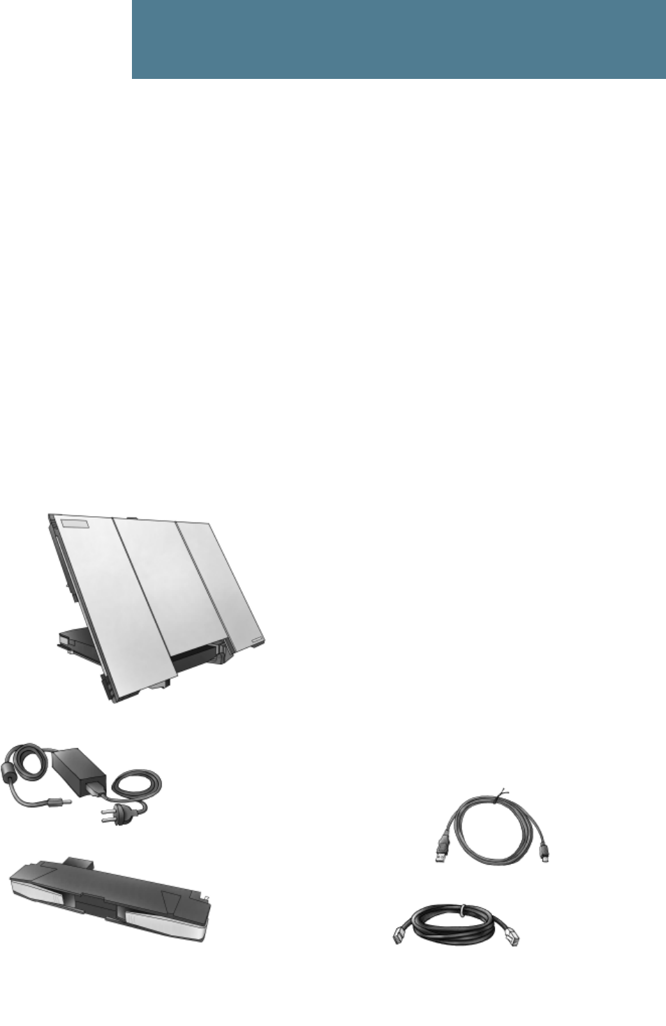
Unpacking and assembling
Unpacking
Unpack the EXPLORER™ 700 and accessories and check that the following items are present:
41.5 cm antenna cable
LAN cable
AC/DC adapter/charger
Battery
USB cable
EXPLORER™ 700
Getting Started Kit
— Getting Started leaflet
— Quick Guide
— EXPLORER™ 700 CD-ROM
— BGAN LaunchPad CD-ROM
containing:
10 m antenna cable
Chapter 2: Getting started
98-122988-DraftB6 13
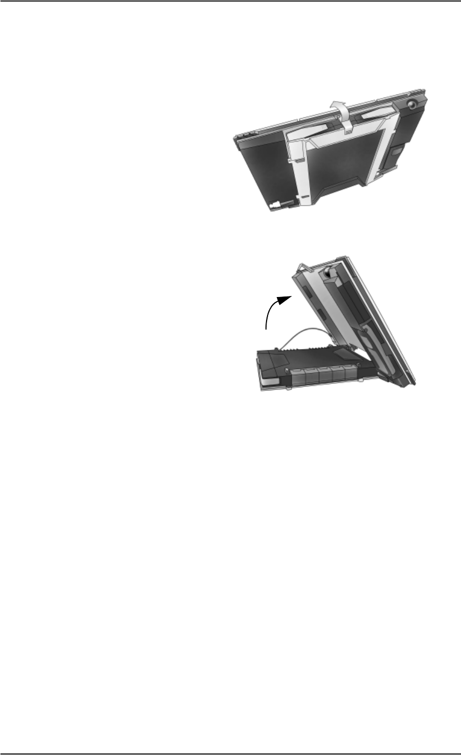
Opening the transport latch
The EXPLORER™ 700 has a transport latch, securing the transceiver and antenna during transport.
Open the latch as shown.
You can now flip up the antenna module
and access the keypad and connectors on
the EXPLORER™ 700.
Chapter 2: Getting started
98-122988-DraftB6 14
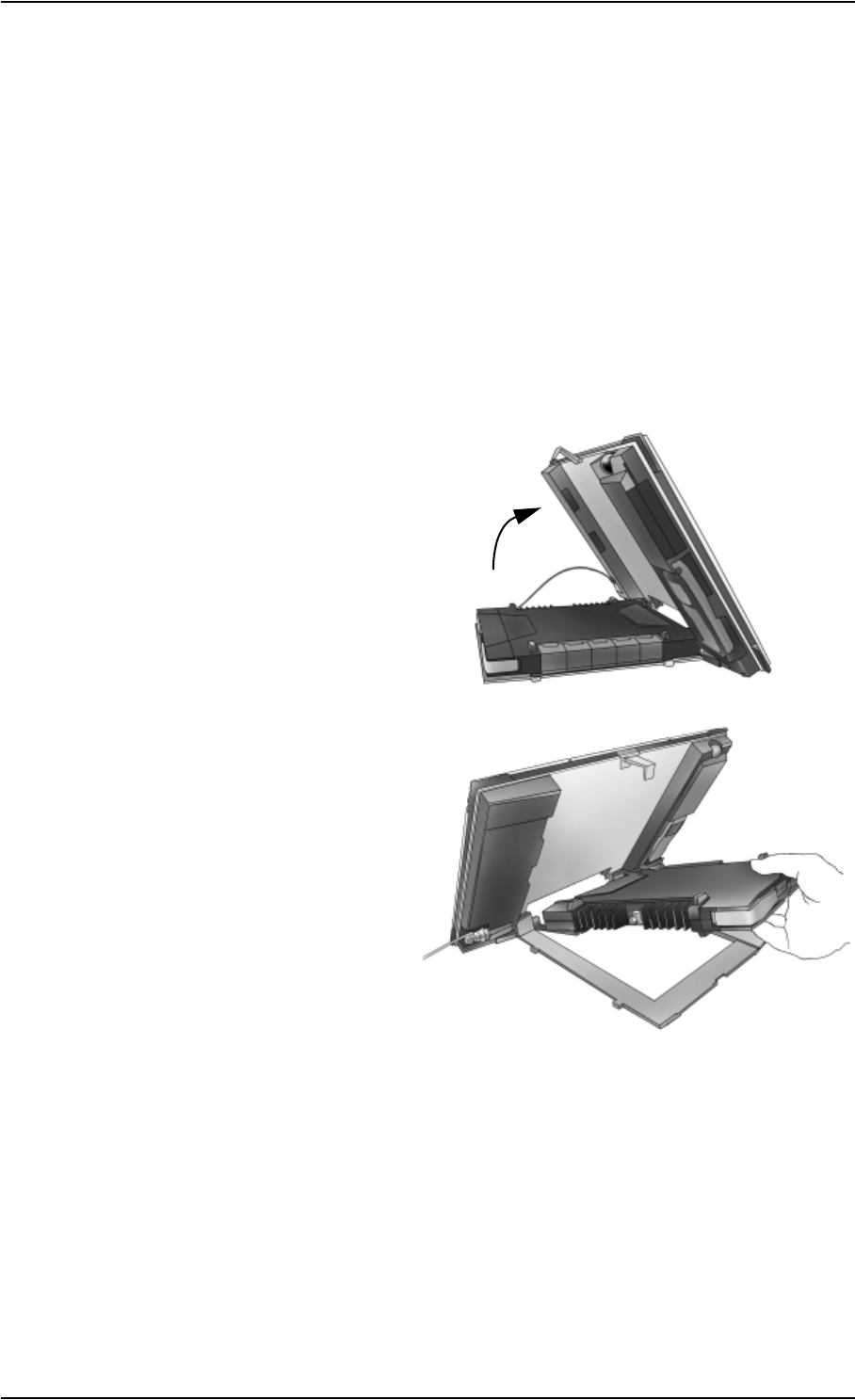
Detaching the antenna
You have two options for using the EXPLORER™ 700 antenna:
•Attached. You can go through the pointing process with the antenna and transceiver attached
as one unit. This means you have to move the entire terminal in order to point the antenna
towards the BGAN satellite. If you choose this option, make sure you connect all cables
including the short antenna cable, and enter the PIN code, before pointing the antenna. If
not, you may accidently move the antenna when you connect cables or enter the PIN code.
•Detached. You can detach the antenna and use it as a separate antenna. With the antenna
separated from the transceiver, it is easier to use the transceiver without accidently moving
the antenna. Also, you can choose the optimum location for the antenna while keeping the
transceiver in a more comfortable location.
To detach the antenna, do as follows:
1. Flip up the antenna module.
2. Gently lift the transceiver out of the
antenna frame.
After detaching the antenna connect an antenna cable between the antenna and the
EXPLORER™ 700 as described in Connecting the antenna on page 76.
Chapter 2: Getting started
98-122988-DraftB6 15
Inserting the SIM card
The EXPLORER™ 700 is delivered with the battery separated from the terminal. If the battery is
already inserted, remove it as described in Removing the battery on page 16.
There are two SIM slots in the EXPLORER™ 700, marked USIM #1 and USIM #2. USIM #2 is
reserved for future use.
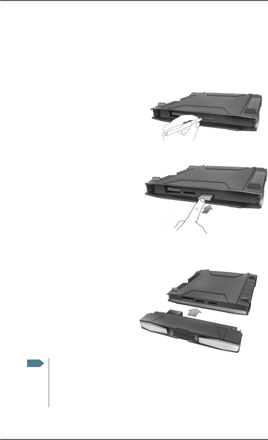
The SIM card is provided by your Airtime Provider. Insert the SIM card as follows:
1. First press the eject button at the SIM slot
marked USIM #1 to release the SIM card
holder. Use a pen or similar to press the
button.
The SIM card holder is a small plastic
frame designed to hold the SIM card.
2. Take the SIM card holder out and place the SIM card in the holder, with the printed side
visible.
3. Insert the holder with the SIM card into
the SIM slot marked USIM #1.
Place the holder with the printed side
facing down.
4. Press gently until it clicks.
Inserting the battery
Do as follows:
1. Insert the battery.
Make sure the battery is positioned
correctly as shown.
2. Press gently until it locks.
Note Before using the terminal the first time: To ensure accurate information on the battery
capacity you should fully charge, then fully discharge the battery (until the
EXPLORER™ 700 closes down automatically), and finally recharge the battery. The
EXPLORER™ 700 can be used during the discharging process, but the remaining battery
capacity may not be displayed correctly.
For information on how to recharge the battery, see Recharging the battery on page 134.
Chapter 2: Getting started
98-122988-DraftB6 16
Removing the battery
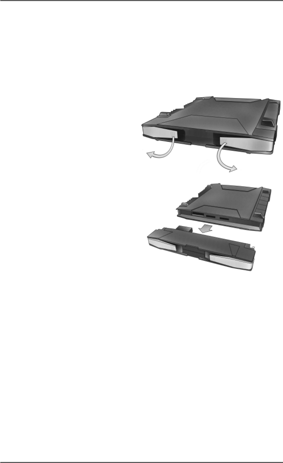
To remove the battery, do as follows:
1. If the transceiver and antenna are attached, open the transport latch and flip up the antenna
module. Then gently lift the transceiver out of the antenna frame.
2. Open the battery latches as shown.
3. Remove the battery.
Chapter 2: Getting started
98-122988-DraftB6 17
Removing the SIM card
To remove the SIM card, first remove the battery as described in Removing the battery on page 16.
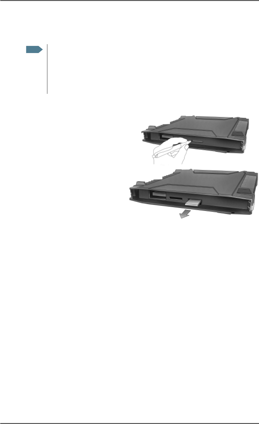
Remove the SIM card as follows:
1. Press the eject button next to the SIM
slot marked USIM #1.
Use a pen or similar to press the
button.
2. Remove the SIM card holder.
3. Take the SIM card out of the holder. Reinsert the holder.
Note When the SIM card is removed, you cannot use the display menu system nor make calls
or start data sessions.
Only emergency calls are allowed, and only if permitted by the network.
However, if you have an administrator user name and password, you can upload
software using the web interface. For further information, see Uploading software on
page 122.
Chapter 2: Getting started
98-122988-DraftB6 18
Connecting cables
After inserting SIM card and battery, connect all relevant cables.
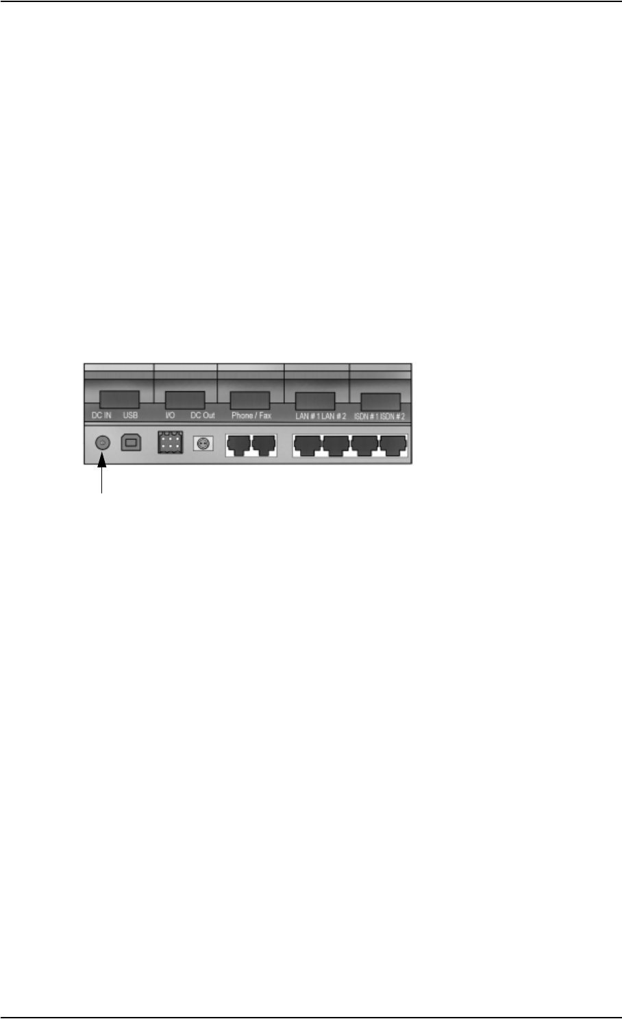
Connectors
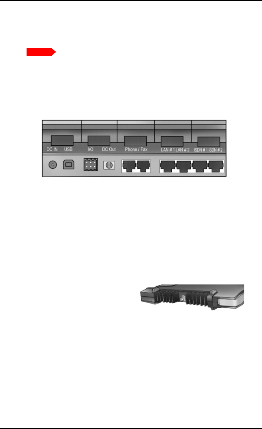
The connector panel is placed on the side of the EXPLORER™ 700 and has the following
connectors:
• 1 DC power input connector for connection to10-32 V DC.
• 1 USB connector
• 1 Input/Output connector for external control or signaling
• 1 Bluetooth Handset charging connector (marked DC OUT)
• 2 Phone/Fax connectors
• 2 LAN connectors
• 2 ISDN connectors
In addition to the connectors in the connector panel, the EXPLORER™ 700 has two connectors for
connecting the antenna,
• one on the transceiver
and
• one on the antenna
For information on how to connect to a specific interface, see the corresponding section in
Chapter 4, Using the interfaces. The end of this section describes how to connect to power.
Important If you are using the transceiver with the antenna attached, connect the cables
before making the final adjustment of the antenna position. Otherwise you may
accidently move the antenna when you connect the cables.
Chapter 2: Getting started
98-122988-DraftB6 19
Before connecting to power
You can connect to external power or use the battery delivered with your EXPLORER™ 700.
Refer to Power input on page 155 for specifications and pin-out for the DC power input.
If you are connecting to a 100-240 V AC electrical outlet, use the AC/DC adapter included with your
EXPLORER™ 700.
Alternatively, you may connect to 12/24 V DC in a car., or to a solar panel. Note that the battery
must be inserted before you connect the EXPLORER™ 700 to a solar panel.
Connecting to power
You can connect the DC input to power without the battery inserted. Note, however, that if you are
connecting a solar panel, the battery must be inserted.
If the battery is inserted when you apply power to the EXPLORER™ 700, the battery is
automatically recharged.
Connecting to a 100-240 V AC electrical outlet: Connect the AC/DC adapter to the DC power input
on the side of the EXPLORER™ 700. Then connect the power cable between the 100-240 V AC
electrical outlet and the AC/DC adapter.
Connecting to 12/24 V DC in a car: Connect the charger cable between the DC power input of the
EXPLORER™ 700 and the cigarette lighter socket in the car. A suitable charger cable is available
from Thrane & Thrane.
Connecting to a solar panel: The battery must be inserted in the EXPLORER™ 700. Connect your
cable between the solar panel and the DC power input of the EXPLORER™ 700. The battery is
automatically charged. For further information, see Using a solar panel on page 77.
Chapter 2: Getting started
98-122988-DraftB6 20
Powering the EXPLORER™ 700
Automatic power up
The default behavior of the EXPLORER™ 700 is to power up automatically when you connect the
power cable. If you wish, you can change this power up mode, so that the EXPLORER™ 700 is only
powered if the power button is pressed.
For further information on power up mode, see Setting the power up mode on page 40 or Power
up behavior on page 99.
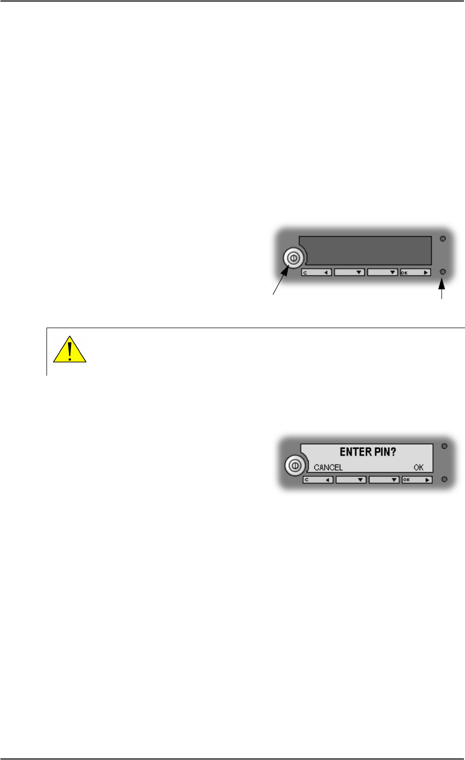
Switching the EXPLORER™ 700 on/off
To switch on the EXPLORER™ 700,push the
Power button next to the display and hold it
down until the green Power indicator lights up.
It normally takes one or two seconds.
To switch off the EXPLORER™ 700, push the power button again and hold it until the display
shows SWITCHING OFF….
After switching on the EXPLORER™ 700 you will
be prompted for a PIN (Personal Identification
Number), unless the PIN is disabled (e.g. using
the BGAN LaunchPad)
For information on the options after power on, see the next section.
WARNING! When the EXPLORER™ 700 is powered on, stay clear of the antenna
front! The antenna emits radio frequency energy, not only when the display shows
DATA ACTIVE. Always keep a minimum distance of 1 m from the antenna front.
Power
button
Power
indicator
Chapter 2: Getting started
98-122988-DraftB6 21
Options for the start-up procedure
Overview of the start-up options
You have different options for the start-up procedure. Each of these options are briefly described
in this section.
For information on how to enter PIN and point the antenna, see the subsequent sections.
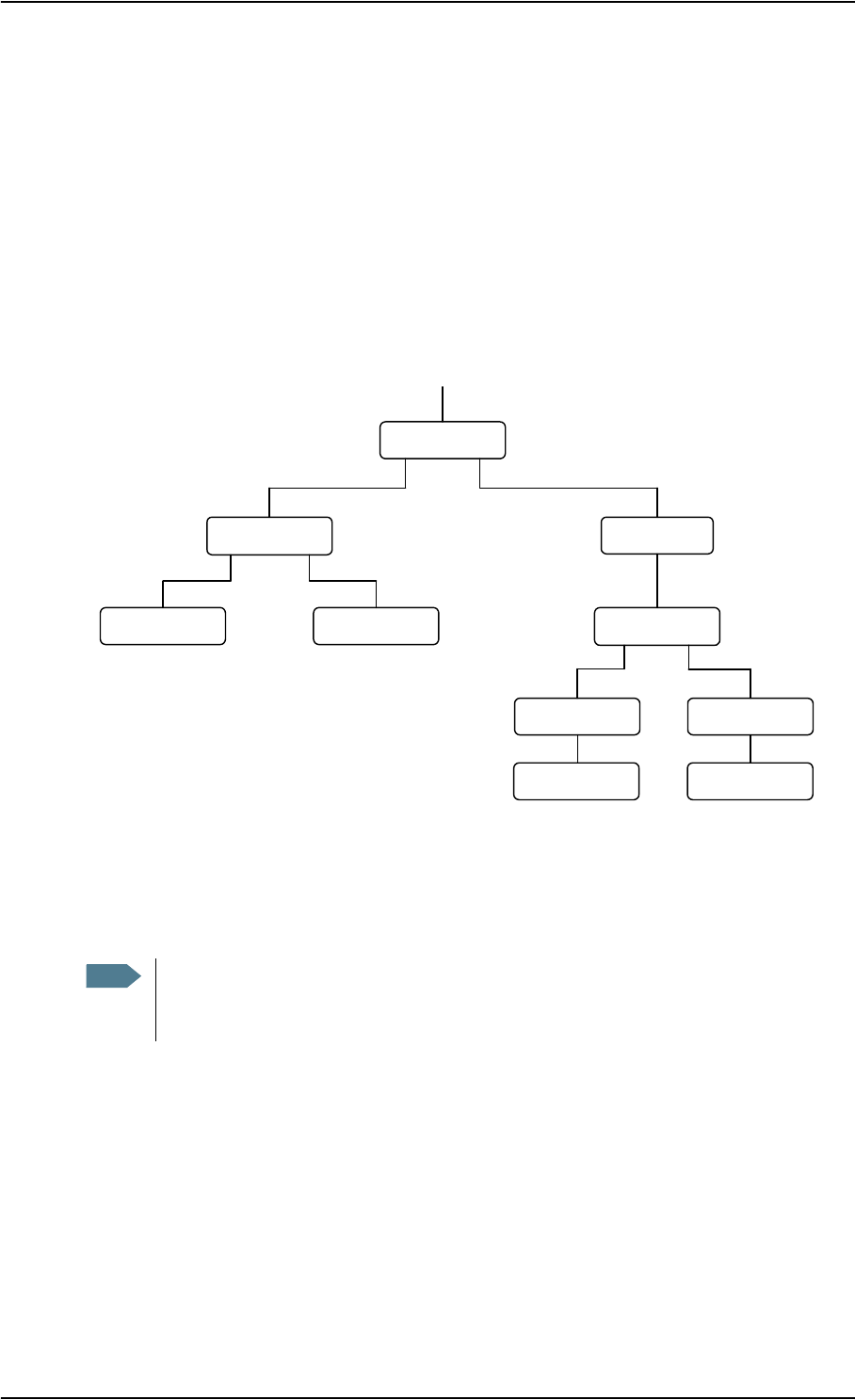
The following drawing shows the options available after power on.
The numbers on the drawing refer to the different start-up options described in the following
sections.
Note If the use of PIN is disabled, e.g. from the BGAN LaunchPad, the display sequence is the
same as after successfully entering the PIN. This means that after power on, you will see
the Signal strength screen.
Power on
ENTER PIN?
Cancel OK
ENTER PIN
*-
«Signal Strength»
Cancel OK
«Signal Strength»
Cancel OK
«Main screen» «Main screen»
You can access the
menu system but you
cannot use the BGAN
network.
You can access the
menu system and use
the BGAN network.
«Main screen«
You cannot access the
menu system, and you
cannot use the BGAN
network.
«Main screen»
You cannot access the
menu system, and you
cannot use the BGAN
network, except for
emergency calls, if
allowed by the network.
Menu system Menu system
12
3

Chapter 2: Getting started
98-122988-DraftB6 22
“Full” procedure (1)
After power on, enter the PIN and then point the antenna.
In this mode you have full access to the EXPLORER™ 700, that is you can use the menu system and
communicate on the BGAN network.
The display will show READY when the menu system is not activated.
“Off-line” procedure (2)
After power on, enter the PIN, but cancel pointing.
In this mode you can use the menu system, but are not able to communicate on the BGAN
network.
The display will show POINT NOW? when in the Main screen.
Press S or T to enter the menu system.
When you want to point the antenna, press OK from the Main screen.
“Emergency” procedure (3)
After power on, cancel the PIN and then point the antenna.
In this mode you can only place emergency calls, and only if permitted by the network. You are not
able to access the menu system nor to communicate on the BGAN network (apart from emergency
calls), until you enter the PIN.
The display will show ENTER PIN?
If you press OK you can enter the PIN. No other options are available from the keypad.
From the web interface you can view properties and, if you have an administrator password,
upload software.
Chapter 2: Getting started
98-122988-DraftB6 23
Entering the SIM PIN
Overview
You have to enter a PIN to use the EXPLORER™ 700, unless the use of PINs is disabled e.g. from
the BGAN LaunchPad.
The first time you are asked for a PIN, you can choose to cancel (press C). If you cancel, you are
asked again after pointing is completed. At that point you must enter the PIN to be able to
continue.
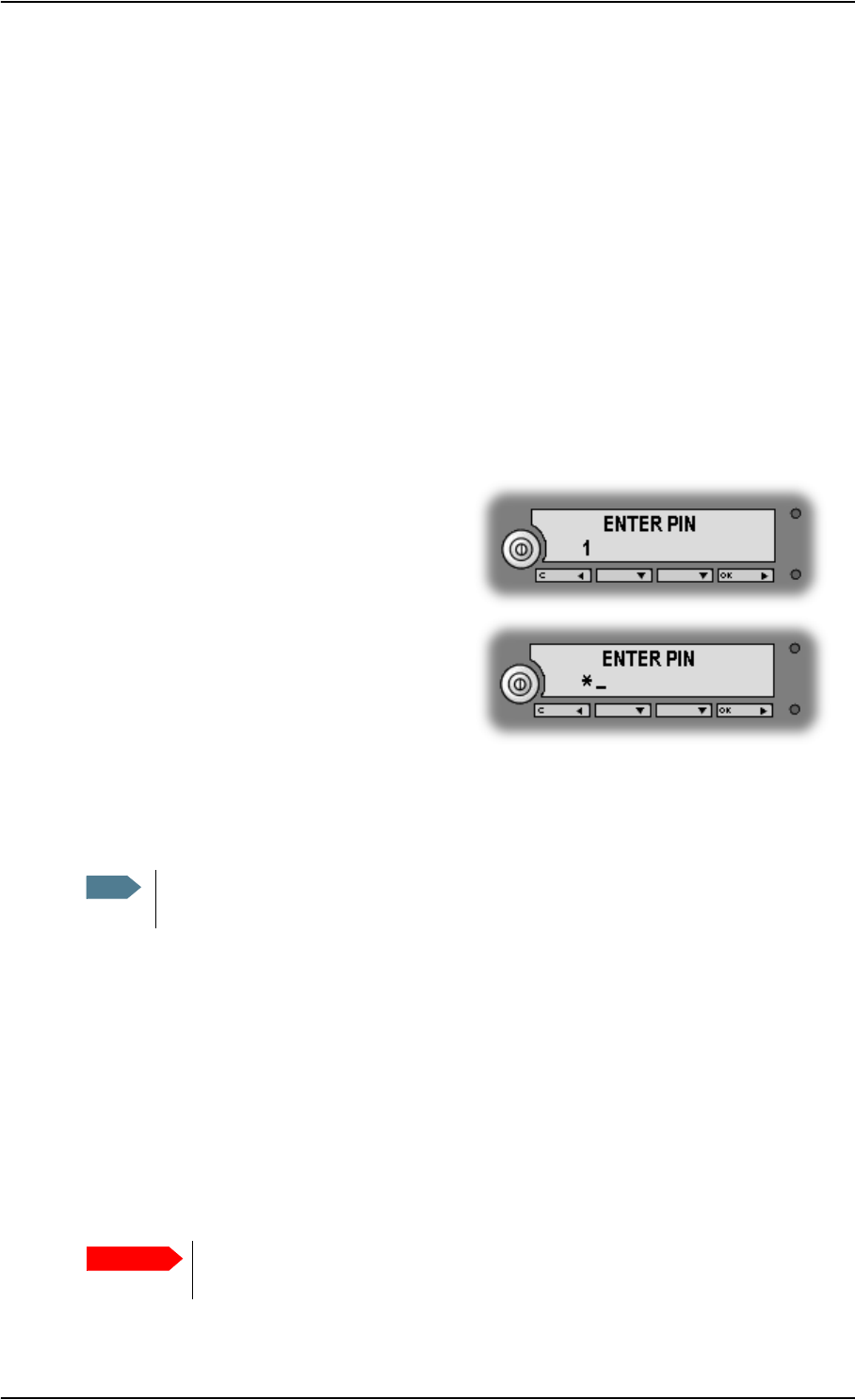
Entering the PIN
To enter the PIN using the display and keypad, do as follows:
1. When you are asked for a PIN, press OK.
2. Press S or T a number of times until the
first digit is correct.
3. Press OK to go to the next digit.
When OK is pressed, the previous digit is
indicated by a *.
To correct an entered digit, press C to go back and use the S and T buttons again.
4. After entering the last digit with OK, press OK again to apply the PIN.
For further information on how to use the keypad and display, see Using the display and keypad
on page 32.
You can enter the PIN using a phone or computer connected to the EXPLORER™ 700. For further
information, see Entering the SIM PIN using a phone on page 56 or Entering the SIM PIN in the
web interface on page 85.
Wrong PIN
You have 3 attempts to enter the PIN, before you are asked to enter the PUK (Pin Unblocking Key).
The PUK is supplied with your SIM card.
Enter the PUK followed by a new PIN of your own choice. The PIN must be from 4 to 8 digits long.
Note At this point the EXPLORER™ 700 may make a sound. This sound is used for pointing the
antenna. To toggle the pointing sound on/off, press S or T.
Important If you enter a wrong PUK 10 times, the SIM card will no longer be functional, and
you have to contact your Airtime Provider for a new SIM card.
Chapter 2: Getting started
98-122988-DraftB6 24
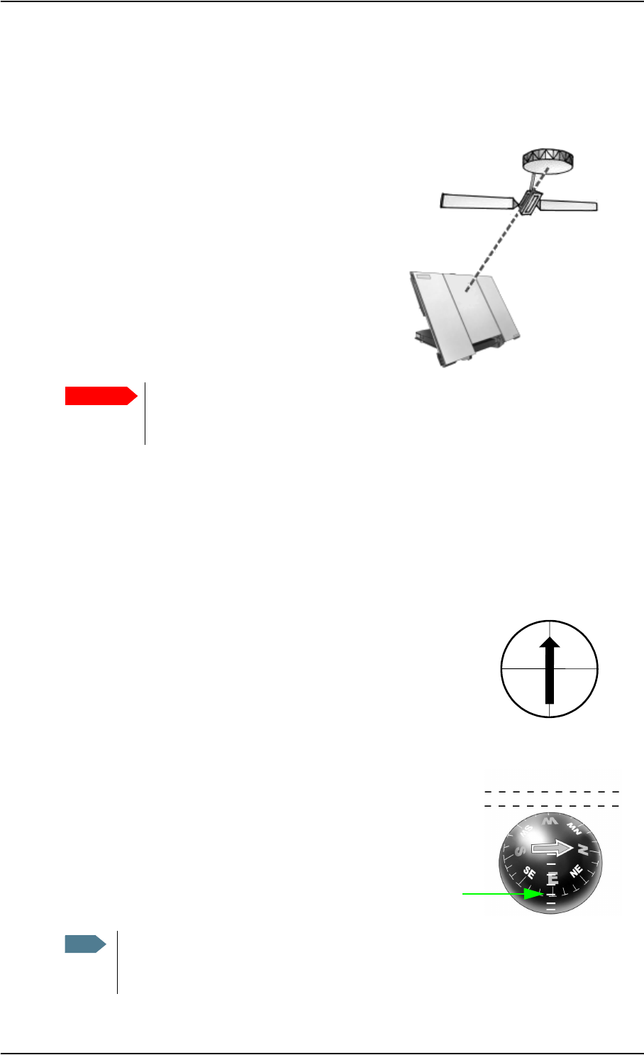
Pointing the antenna
The importance of pointing
In order to obtain the best possible signal at the
lowest possible cost, it is important that the
EXPLORER™ 700 antenna is pointed correctly
towards the satellite.
The antenna must have a clear line of sight to the
satellite without any obstacles blocking the signal,
and the pointing direction of the antenna should be
as accurate as possible.
The next sections describe how to point the antenna for the best possible signal.
Pointing data
If the position of the satellite in relation to the EXPLORER™ 700 is known, you can use the
compass to roughly point the antenna in the right direction. If you know the Azimuth and the
Elevation, you can use this data to adjust the antenna.
•The Azimuth is the horizontal rotation angle relative to
North (moving clockwise).
•The Elevation is the vertical rotation angle relative to
horizontal. This means that an Elevation of 0° corresponds to
the EXPLORER™ 700 being in an upright position, pointing
towards the horizon.
The compass has 7 lines dividing the Elevation scale into 6
spaces. The space between two lines corresponds to 15°.
The Elevation is measured where the lines meet. This compass
shows an Elevation of 30° (2 spaces up from the first line) and an
Azimuth of 270° (antenna pointing towards West).
Important Incorrect pointing may result in poor quality of the signal, and in some cases
retransmission may be necessary. This could mean you will be paying more than
necessary for your transmission.
Note The above explanation assumes that the compass shows the exact orientation. Please
take into consideration the possible deviation and variation that can occur, e.g. because
of the geographical location or the presence of magnetic objects.
N = 0°
S = 180°
E = 90°W = 270°
Front of antenna

Chapter 2: Getting started
98-122988-DraftB6 25
Required signal strength
As a rule of thumb, the signal strength should typically be 45 dBHz or more for the
EXPLORER™ 700 to be able to establish a call or data session. However, the required signal
strength can vary depending on a number of factors, such as weather conditions and location.
Do not block the antenna signal with your hands
Obtaining a GPS fix
The EXPLORER™ 700 must acquire its own location from the GPS satellites before it can register
on the BGAN network. This is called obtaining a GPS fix.
If the antenna is placed in an open location with a wide view to the sky, the EXPLORER™ 700 will
probably obtain the GPS fix automatically while you are pointing towards the BGAN satellite.
However, if part of the view to the sky is blocked, and/or the Elevation is very low, it may
sometimes be difficult for the GPS antenna to “see” a sufficient number of GPS satellites. In such
circumstances, try the following:
1. Place the antenna flat on an even surface pointing straight upwards, with a clear view to as
much of the sky as possible.
2. When the GPS fix is obtained, you can start pointing towards the BGAN satellite.
To see the GPS status, enter the display menu system by pressing S or T and select
PROPERTIES > GPS STATUS. For further information, see Viewing the GPS status on
page 42.
Important When pointing the antenna, do not touch the front of the antenna module. For your
safety, always maintain a distance of minimum 1 m from the front face of the
antenna. Also, if you place your fingers on the antenna you will be blocking the
signal, and the antenna will not work efficiently.
Hold the support bracket and the transport lock of the antenna while pointing.
Chapter 2: Getting started
98-122988-DraftB6 26
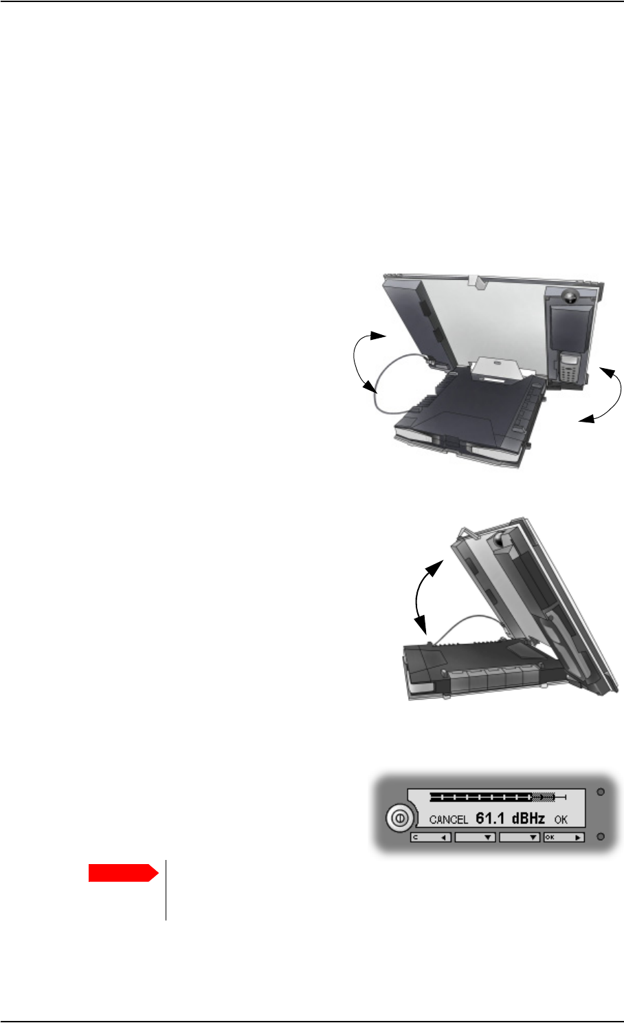
Pointing the antenna towards the satellite
You can use the EXPLORER™ 700 with the antenna attached to the transceiver, or you can detach
the antenna from the transceiver and use it as a separate antenna unit. For further information,
see Using the EXPLORER™ 700 antenna on page 76.
To help you obtain the best possible signal strength, the EXPLORER™ 700 uses a pointing sound
from both antenna and transceiver to indicate the signal strength during pointing. The frequency
of the tone increases with the signal strength.
You can toggle the pointing sound on/off by pressing S or Ton the keypad.
Do as follows to point the antenna:
1. While observing the built-in compass of the
EXPLORER™ 700, rotate the antenna left or
right until it points in the correct horizontal
direction, known as the Azimuth. Refer to
Pointing data on page 24.
Hold the transport lock and the support
bracket while moving the antenna. Do not
place your hands on the antenna.
2. Tilt the antenna slowly up or down until it points in
the correct vertical direction, known as the
Elevation.
Hold the transport lock and the support bracket
while moving the antenna. Do not place your hands
on the antenna.
3. After passing the PIN screen, the display shows
the current satellite signal strength. Use this
information to fine-adjust the antenna position
as shown in step 1 and 2.
Remember not to touch the antenna part!
If the right most part of the signal strength bar is grey, it indicates that the level has previously
been higher than the current level.
Important When fine-adjusting the antenna, the display may take a while to update the
signal strength. Wait a second or two after each move to make sure the display
is updated.

Chapter 2: Getting started
98-122988-DraftB6 27
4. When you have the highest signal strength you
can obtain, press OK on the keypad.
The EXPLORER™ 700 now tries to establish a connection to the BGAN network.
The display shows the progress as follows:
•SEARCHING: The EXPLORER™ 700 searches for the network operator. Note that the
search procedure can be very short, so you may not see this text.
•REGISTERING: The EXPLORER™ 700 is registering itself on the network.
If the GPS position has not yet been acquired at this point, the display will show
NO GPS. For further information, see the Troubleshooting Guide on page 138.
•READY or DATA ACTIVE: READY means the EXPLORER™ 700 is registered on the
network and is ready to go online. If you have already connected a computer, the display
shows DATA ACTIVE instead of READY.
CANCEL: If you press C instead of OK, you exit the pointing menu and the display shows the Main
screen with the message POINT NOW?.
If the PIN has been accepted, you now have access to the menu system, but you will not be able to
connect to the BGAN network, because the signal strength has not yet been accepted.
Note The display may show a different text than READY or DATA ACTIVE if there is more
important information to show. For example, the display will show ENTER PIN? if you
pressed C at the first request for a PIN. See also the Troubleshooting Guide on page 138.

Chapter 2: Getting started
98-122988-DraftB6 28
Making the first call
Introduction
After connecting cables, entering the PIN and pointing the antenna, you are ready to make or
receive the first call.
The following sections provide a short guide to making calls. For more detailed information, see
Making or receiving a phone call with the EXPLORER™ 700 on page 57.
Making a call from the EXPLORER™ 700
Your phone must be connected to the relevant interface. For further information, see
•Standard phone: Before connecting to the Phone/Fax interface on page 53
•ISDN phone: Before connecting to the ISDN interface on page 54.
• Bluetooth handset: Pairing devices in which you can enter a passkey on page 50.
To make a call from a phone connected to the EXPLORER™ 700, dial
00 <country code> <phone number> followed by # or off-hook key (# on analog phones and ISDN
phones, off-hook key on Bluetooth handsets).
Example: To call Thrane & Thrane in Denmark (+45 39558800) from an analog phone, dial 00
45 39558800 #
Making a call to the EXPLORER™ 700
To make a call to a phone connected to the EXPLORER™ 700, dial
+870 <Mobile subscriber number>
•+ is the prefix used in front of the country code for international calls. This is 00 when calling
from most countries in Europe and from many other countries.
•Mobile subscriber number: The mobile subscriber number of the EXPLORER™ 700 you are
calling.
If the mobile subscriber numbers of the EXPLORER™ 700 are available on the SIM card, they
are listed in the display menu system of the EXPLORER™ 700 under PROPERTIES >
MOBILE NUMBERS. If they are not available, refer to your airtime subscription.
Example: If you are calling from Denmark and the mobile subscriber number for 3.1 kHz Audio is
772112345 on your EXPLORER™ 700, and you want to make a call to the EXPLORER™ 700 using 3.1
kHz Audio, dial 00 870 772112345.
Note There are two voice numbers, one for 3.1 kHz Audio and one for Standard Voice.

Chapter 2: Getting started
98-122988-DraftB6 29
Making a call from one EXPLORER™ 700 to another EXPLORER™ 700
To make a call from a phone connected to one EXPLORER™ 700 to a phone connected to another
EXPLORER™ 700, dial 00 870 <Mobile subscriber number>.
Receiving a call
To be able to receive a call, the phone must be connected to the correct interface of the
EXPLORER™ 700 (Phone/Fax, ISDN or Bluetooth).
To be able to receive a call with a Bluetooth handset, the handset must be paired with the
EXPLORER™ 700. For information on how to pair Bluetooth devices, see Bluetooth pairing on
page 50.
You can see unanswered calls in the CALLS menu of the display and the web interface.
Note A connected phone will only ring if the call type is set correctly. For information on call
types, see Selecting the call type on page 51.
Chapter 2: Getting started
98-122988-DraftB6 30
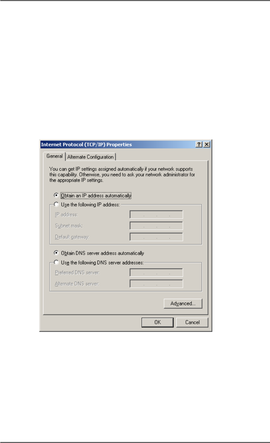
Making the first data connection (LAN)
Before connecting to the LAN interface
For the LAN (Local Area Network) interface to work without any further setup, the computer must
be set up to obtain an IP address and a DNS server address automatically.
To check these settings on your computer, do as follows (For Windows® XP):
1. From the Start menu, select Connect To > Show All Connections.
2. Double-click Local Area Connection and click Properties.
3. Select Internet Protocol (TCP/IP) from the list and click Properties.
Make sure both fields are set to obtain an address automatically.

Chapter 2: Getting started
98-122988-DraftB6 31
Connecting to the LAN interface
Do as follows:
1. Connect the LAN cable to the network interface of your computer.
A suitable cable is provided with your EXPLORER™ 700.
2. Connect the other end of the
cable to one of the LAN
connectors on the
EXPLORER™ 700.
3. Start up and point the EXPLORER™ 700 as described earlier in this chapter.
4. Power on the computer.
5. When power up and pointing is completed, check the connection e.g. by starting your Internet
Browser.
You may have to disable the Proxy server settings in your browser. For further information,
see Browser settings on page 81.
What’s next?
After reading this chapter you should be able to start up the EXPLORER™ 700 and make a simple
data or voice connection.
The next chapters provide more information on the user interfaces and the setup of the
EXPLORER™ 700. The following chapter, Using the display and keypad, explains the display menu
system, which is the basic tool for setting up the EXPLORER™ 700.

98-122988-DraftB6 32
Chapter 3
Using the display and keypad 3
In this chapter
This chapter describes how to use the built-in display menu system of the EXPLORER™ 700.
It contains an overview of the entire menu system followed by a description of each menu.
It also explains the symbols and messages that may appear in the display, and describes how to
navigate using the keypad.
Menu overview
Main menu
The items of the main menu are:
•MESSAGES
shows all incoming SMS messages and allows you to open or delete each message or delete
all messages.
•CONNECT
shows a list of the Streaming Profiles that are defined and selected for the LAN interface using
the web interface. The CONNECT menu allows you to start and stop data sessions with the
listed Streaming Profiles.
•CALLS
shows missed, received and outgoing calls (Voice only).
•SETTINGS allows you to
• restart the pointing procedure,
• set display backlight and contrast,
• set audio indications on or off,
• enable or disable each interface,
• enable or disable stealth mode
(a terminal mode where lights and sound are off),
• set the power up mode, and
•restore settings.
•PROPERTIES shows:
• known and accepted Bluetooth devices,
•GPS status,
• IP address, hardware and software numbers,
• IMEI number, mobile subscriber numbers and voice mail numbers, and
• a list of active alarms.

Chapter 3: Using the display and keypad
98-122988-DraftB6 33
•HELP DESK
shows the phone number to the Airtime Provider, if available.
For information on how to navigate in the menu system, see Navigating the display and keypad on
page 36.
Menu drawing
The below drawing shows an overview of the menus in the display menu system of the
EXPLORER™ 700.
The next section shows an overview of the start-up sequence before entering the menu system.
The menus are further described in the following sections of this chapter.
2 SECONDS
5 SECONDS
10 SECONDS
30 SECONDS
60 SECONDS
LEVEL 1
LEVEL 2
LEVEL 3
LEVEL 4
LEVEL 5
LEVEL 6
LEVEL 7
ON
OFF
TIMED
SET LEVEL
AUTOMATIC
SET LEVEL
LEVEL 1
LEVEL 2
LEVEL 3
LEVEL 4
LEVEL 5
LEVEL 6
LEVEL 7
POINTING
MESSAGES
ALARM
ON
OFF
PHONE/FAX
BLUETOOTH
LAN
ISDN
WLAN
ENABLED
DISABLED
PIN Code
Start up
ON
OFF
UNIT SER. NO.
MAIN PCB NO.
HPA PCB NO.
MAC
MAC WLAN
(Pointing)
BLUETOOTH DEVICES
GPS STATUS
TERMINAL
MOBILE NUMBERS
VOICE MAIL NUMBER
ALARM LIST
<message 1>
<message 2>
<message 3>
<message 4>
DELETE ALL
MESSAGES
CONNECT
CALLS
SETTINGS
PROPERTIES
HELP DESK
MISSED
RECEIVED
OUTGOING
POINT NOW
DISPLAY
AUDIO INDICATOR
INTERFACES
STEALTH MODE
POWER UP MODE
RESTORE SETTINGS
1 <device>
2 <device>
3 <device>
4 <device>
5 <device>
6 <device>
7 <device>
IP ADDRESS
HARDWARE
SOFTWARE
IMEI
OPEN
DELETE MESSAGE
AUTOMATIC
MANUAL
BACKLIGHT
CONTRAST
<streaming profile 1>
<streaming profile 2>
<streaming profile 3>
START
STOP
Chapter 3: Using the display and keypad
98-122988-DraftB6 34
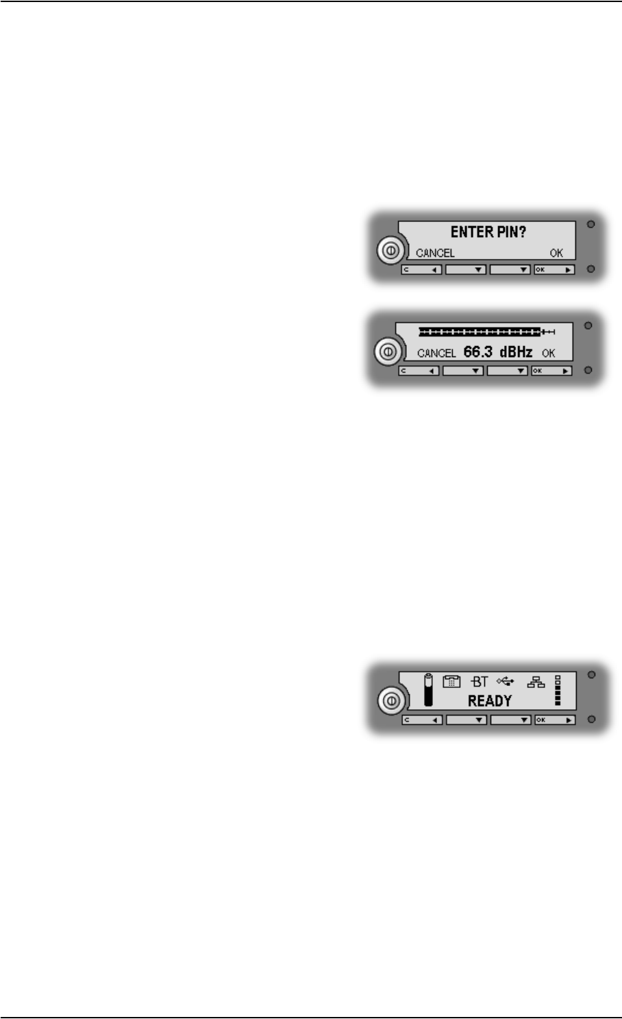
Display during start-up
Start-up sequence
There are different options for the start-up procedure. The complete startup procedure is
described in Chapter 2, Getting started.
This section only describes the behavior of the display during normal startup.
After power on you are asked for a PIN:
When you press OK and enter PIN, the signal
strength screen appears.
When you have pointed the antenna and pressed OK to accept the signal strength, the display
shows the progress in the Main screen as follows:
•SEARCHING: The EXPLORER™ 700 is searching for the network operator.
•REGISTERING: The EXPLORER™ 700 is registering itself on the BGAN network.
If the GPS position has not yet been acquired at this point, the display will show
NO GPS. For further information, see the Troubleshooting Guide on page 138.
•READY: The EXPLORER™ 700 is registered on the network and is ready to go online.
If a computer is already connected, the display will show DATA ACTIVE instead of READY.
Main screen
The Main screen is shown after passing the PIN
and pointing screens, and anytime you leave the
menu system.
The Main screen shows the most important status
of the EXPLORER™ 700 such as battery status,
signal strength, and general status.
The Main screen also shows icons for any interfaces that are turned on. In this example, the
interfaces Phone/Fax, Bluetooth, USB and LAN are turned on.
Chapter 3: Using the display and keypad
98-122988-DraftB6 35
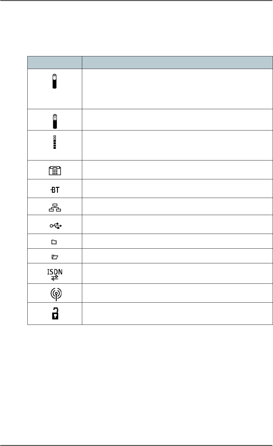
Display symbols
Apart from the menu text, the display can show various symbols. Below is a list of the possible
symbols with an explanation to each symbol.
Symbol Explanation
The battery charge level.
When the level is too low (below 10%) the icon flashes. Recharge the
battery as soon as possible.
If no battery is inserted, the symbol is not shown in the display.
The battery is charging.
The signal strength.
Minimum two bars are normally required to be able to make a Standard
Voice call.
Phone/Fax interface is on.
Bluetooth interface is on.
LAN interface is on.
USB interface is on.
Unread message (shown next to the message in the message list)
Read messages (shown next to the message in the message list)
ISDN interface is on.
WLAN interface is on.
The current connection on the BGAN network is not ciphered. Do not
transmit data that requires ciphering.

Chapter 3: Using the display and keypad
98-122988-DraftB6 36
Navigating the display and keypad
Navigating with the keypad
The PIN must be entered before you can access the menu system.
•To access the menu system from the Main screen, press S or T.
•To move up and down in the current menu, press S or T.
•To select the current menu item or setting, press OK.
•To escape the current menu/setting and return to the previous level, press C.
•To see the hidden part of long text strings, press X.
•To move backwards in the menu system, or in long text strings, press W.
•To adjust settings, press S and T.
Short-cuts
The following short-cuts are available in the menu system:
•To exit the menu system, press and hold C for one second. The display returns to the Main
screen.
•To activate/deactivate Stealth mode, Press C+OK.When stealth mode is activated, the display
shows STEALTH ACTIVATED for a moment; then all lights and sounds are turned off.
•To turn Pointing sound on/off, Press S or T from the pointing screen.
This action only applies to the current pointing session. To turn the sound on or off for all pointing
sessions, select
SETTINGS > AUDIO INDICATORS > POINTING and select ON or OFF.
Note In low temperatures the display may respond slowly when a key is pressed. At
temperatures close to -25°C/-13°F the display may even turn black for a moment, e.g.
when you are scrolling through a menu. After 1-2 seconds with no keypad activity the
display will be readable again.
Note For Stealth mode to be available, it must be enabled in the EXPLORER™ 700. Refer
to Enabling or disabling stealth mode on page 40.

Chapter 3: Using the display and keypad
98-122988-DraftB6 37
Display text
When you have not entered the menu system, the Main screen shows the currently most important
information. Refer to Dynamic information in the display on page 45.
CANCEL in the left side of the display means: Press C to cancel the current operation.
OK in the right side of the display means: Press OK to accept the current operation.
The menus
The following sections describe each of the menus in the menu system.
All available settings and status items are explained.
To access the menu system from the
main screen, press S or T.
Messages menu
Viewing the list of messages
To see the list of SMS messages, enter the menu system and select MESSAGES. Each message is
listed with the name (if known) or the number of the sender.
An unopened folder indicates an unread message and an opened folder indicates a read
message.
Use S and T to scroll through the list.
For information on how new messages are presented, see Received messages on page 45.
Opening or deleting received SMS messages
In the MESSAGES list, select the message you want to open or delete and press OK. Then select
one of the following:
•OPEN: to open the selected message.
The display shows the time and the message contents. Use S and T to scroll through the
message and details.
•DELETE: to delete the selected message.
To delete all messages, go to the bottom of the list of messages and select DELETE ALL.

Chapter 3: Using the display and keypad
98-122988-DraftB6 38
Connect menu
Streaming Profiles
Using the web interface you can define a number of Profiles for data transmission. The Streaming
Profiles defined and selected for the LAN interface appear in the CONNECT menu, and can be
started and stopped using the keypad.
Streaming Profiles are Profiles where the Traffic Class is set to Streaming in the Profiles window of
the web interface.
For information on Profiles, see Using Profiles on page 127.
For information on Streaming, see Standard or Streaming data on page 65.
Starting or stopping a Streaming session
To start or stop a Streaming session on the LAN interface, do as follows:
1. Select CONNECT.
2. Select the Streaming Profile you want to start or stop.
The list only shows Profiles that have been selected for the LAN interface.
For information on how to set up the LAN interface, see Configuring the LAN interface on
page 107.
3. Select START or STOP and confirm.
You can also start/stop Streaming sessions using the web interface. For further information, see
Setting up and activating a Streaming connection on page 65.
Calls menu
To see a list of calls or data sessions, select CALLS and then one of the following:
•MISSED: to see a list of incoming calls that were not answered.
•RECEIVED: to see a list of incoming calls that were answered.
•OUTGOING: to see a list of outgoing calls or data sessions.
Select a call from the list to see details such as time, date and phone number. If there was an
error, the call log shows the cause of the error when possible.
When there are more than 100 calls in the list, the oldest calls are automatically deleted to make
room for new calls.
If you need to preserve the call log, you can export it to a file using the built-in web interface. For
further information, see Exporting the call log on page 91.
Important When running a Streaming session you are charged for the time you are
connected. An active Streaming session will stay active until you stop it.
Note Local calls are not registered.

Chapter 3: Using the display and keypad
98-122988-DraftB6 39
Settings menu
Point now
If you need to repoint the antenna after the first pointing process, select SETTINGS > POINT
NOW.
This will bring you to the Pointing screen, described in Pointing the antenna on page 24.
Setting the display backlight
To adjust the backlight of the display, select
SETTINGS > DISPLAY > BACKLIGHT.
From this menu you can set the backlight of the display. Select one of the following:
•ON: to turn the light on.
•OFF: to turn the light off.
•TIMED: to set how long the light should be on after the last key was pressed (2, 5, 10, 30 or
60 seconds).
•SET LEVEL: to set the level of backlight.
Setting the display contrast
To adjust the contrast of the display, select:
SETTINGS > DISPLAY > CONTRAST.
From this menu you can set the contrast of the display. Select one of the following:
•SET LEVEL: to set the contrast manually.
•AUTOMATIC: to let the EXPLORER™ 700 automatically adjust the contrast according to the
temperature.
The contrast of the display is affected by the temperature. The EXPLORER™ 700 can
automatically adjust the contrast so that the display looks the same, regardless of changes in
the temperature.
Turning audio indicators on or off
The EXPLORER™ 700 has audio indicators to indicate an event.
You can turn each of these audio indicators on or off.
Select SETTINGS > AUDIO INDICATOR and select one of the following:
•POINTING: a sound to indicate the signal level during pointing.
•MESSAGES: a sound to indicate that a message has arrived.
•ALARM: a sound to indicate that an alarm is present.
Then select ON or OFF.
Important This function will interrupt any ongoing calls or sessions!

Chapter 3: Using the display and keypad
98-122988-DraftB6 40
Enabling or disabling interfaces
Each interface (except USB) can be disabled to minimize the power consumption. Specially if the
EXPLORER™ 700 is battery powered, it is a good idea to disable unused interfaces.
To turn an interface on or off, select SETTINGS > INTERFACES and select one of the following
interfaces:
• PHONE/FAX
• BLUETOOTH
• LAN
• ISDN
• WLAN
Then select ON or OFF.
Enabling or disabling stealth mode
When the EXPLORER™ 700 is in stealth mode, all lights and sounds are turned off. You can still
use the EXPLORER™ 700, and the display text is readable.
To enable or disable the use of stealth mode, select
SETTINGS > STEALTH MODE and select one of the following:
• ENABLED
•DISABLED
To activate Stealth mode (after enabling Stealth mode), press C+OK on the keypad.
To deactivate Stealth mode, press C+OK again.
Setting the power up mode
By default, the EXPLORER™ 700 starts up automatically when you apply external power. You can
change this mode, so that you always have to press the power button to switch on the
EXPLORER™ 700.
To set the power up mode, select
SETTINGS > POWER UP MODE and select one of the following:
•AUTOMATIC: to have the EXPLORER™ 700 power up automatically when external power is
applied.
•MANUAL: to have the EXPLORER™ 700 power up only when the power button is pressed.
Note Enabling stealth mode will not put the EXPLORER™ 700 into stealth mode, it only
enables the use of stealth mode.

Chapter 3: Using the display and keypad
98-122988-DraftB6 41
Restoring settings
You can restore default values for the settings in the SETTINGS menu, except the contrast
setting. The following settings are restored:
•Backlight
• Audio indicators
• Stealth mode
• Interfaces enabled
•Power up mode
Note that all other settings are left unchanged.
To restore settings, select SETTINGS > RESTORE SETTINGS. Then press OK.
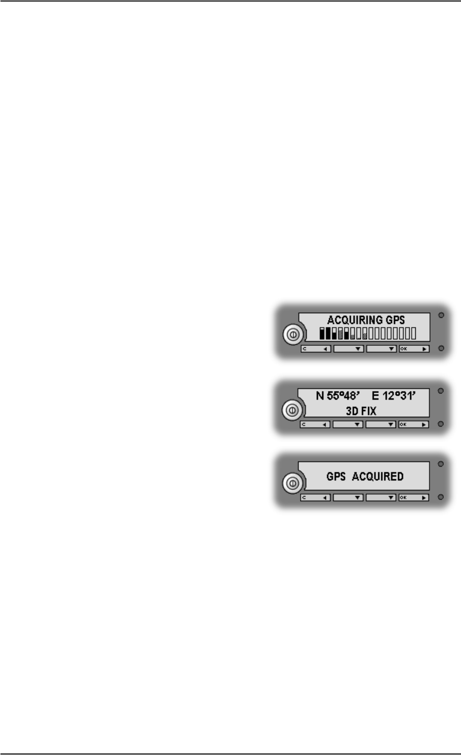
Chapter 3: Using the display and keypad
98-122988-DraftB6 42
Properties menu
Viewing known Bluetooth devices
You can view a list of the Bluetooth devices that are paired with the EXPLORER™ 700. The devices
are listed with their Bluetooth names.
The devices in this list can communicate with the EXPLORER™ 700 without any further setup.
To view the list of known Bluetooth devices, select
PROPERTIES > BLUETOOTH DEVICES.
To see details on a specific Bluetooth device, select the device in the list and press OK.
Viewing the GPS status
The display can show the current GPS status.
To view the GPS status, select PROPERTIES > GPS STATUS.
The GPS status screen can vary, depending on the situation.
• If the GPS position has not yet been obtained,
the display shows the status of each of the 16
GPS satellites as follows:
• If the GPS position is known, the display
shows the GPS position, and whether it is a 2-
dimensional or 3-dimensional position (2D fix
or 3D fix).
• In some cases, the BGAN network does not
allow the position to be displayed to the user.
If this is the case, the display may just show
GPS ACQUIRED. This means that the GPS
position is received, but the user is not
allowed to see it.
This also applies if the EXPLORER™ 700 is not yet registered on the BGAN network, but the
GPS position is received.

Chapter 3: Using the display and keypad
98-122988-DraftB6 43
Viewing terminal properties
You can view properties of the EXPLORER™ 700 such as IP address, hardware numbers, software
version and IMEI number. When contacting Support, please include these numbers.
To view the properties, select PROPERTIES > TERMINAL and select one of the following
options:
•IP ADDRESS to see the IP address of the EXPLORER™ 700. This IP address is used to
access the web interface of the EXPLORER™ 700. The web interface is a built-in web server
used to configure and set up the EXPLORER™ 700. For further information on the web
interface, see Using the web interface on page 80.
•HARDWARE to see the serial number, PCB numbers and MAC addresses of your
EXPLORER™ 700.
•MAC is the MAC address used for the LAN and Bluetooth interface.
•MAC WLAN is the MAC address used for the WLAN interface.
•SOFTWARE to see the software version of the EXPLORER™ 700.
•IMEI to see the IMEI number (International Mobile Equipment Identity) of the
EXPLORER™ 700. This is the unique mobile equipment number that identifies your
EXPLORER™ 700.
Viewing mobile subscriber numbers
If available on the SIM card, the MOBILE NUMBERS menu lists the mobile subscriber numbers
to use when calling the EXPLORER™ 700.
To view the mobile subscriber numbers, select
PROPERTIES > MOBILE NUMBERS.
If the mobile numbers are not available, the display reads
NO INFORMATION AVAILABLE.
Viewing the voice mail number
The EXPLORER™ 700 informs you of any incoming voice mail through the display and through the
web interface.
The voice mail number is the number you call to hear your incoming voice mail.
If available on the SIM card, the PROPERTIES menu shows the voice mail number.
To view the voice mail number, select
PROPERTIES > VOICE MAIL NUMBER.
If the voice mail number is not available, the display reads
NO INFORMATION AVAILABLE.
Note There are two voice numbers, one for 3.1 kHz Audio and one for Standard Voice. For
further information, see Selecting the call type on page 51.

Chapter 3: Using the display and keypad
98-122988-DraftB6 44
Alarm list
If an error is present in the system, an alarm will be issued. For information on how new alarms
are presented, see Display of alarm messages on page 146.
You can always view the list of currently active alarms by entering the menu system and selecting
PROPERTIES > ALARM LIST.
In the alarm list, the alarms are listed with their ID numbers.
To see the name and time stamp of the alarm, press OK. Use S and T to scroll through the name,
ID and time stamp. If the text is too long, press OK (X) to scroll through the rest of the text.
Help desk
If you need support regarding airtime, you may call the Airtime Provider help desk.
To see the help desk number, select HELP DESK in the menu system.
The display will show the name and phone number of your Airtime Provider, if it is available on
the SIM card.
If the information is not available on the SIM card, you can use the built-in web interface of the
EXPLORER™ 700 to store the help desk name and number. For further information, see Accessing
the Help desk on page 132.
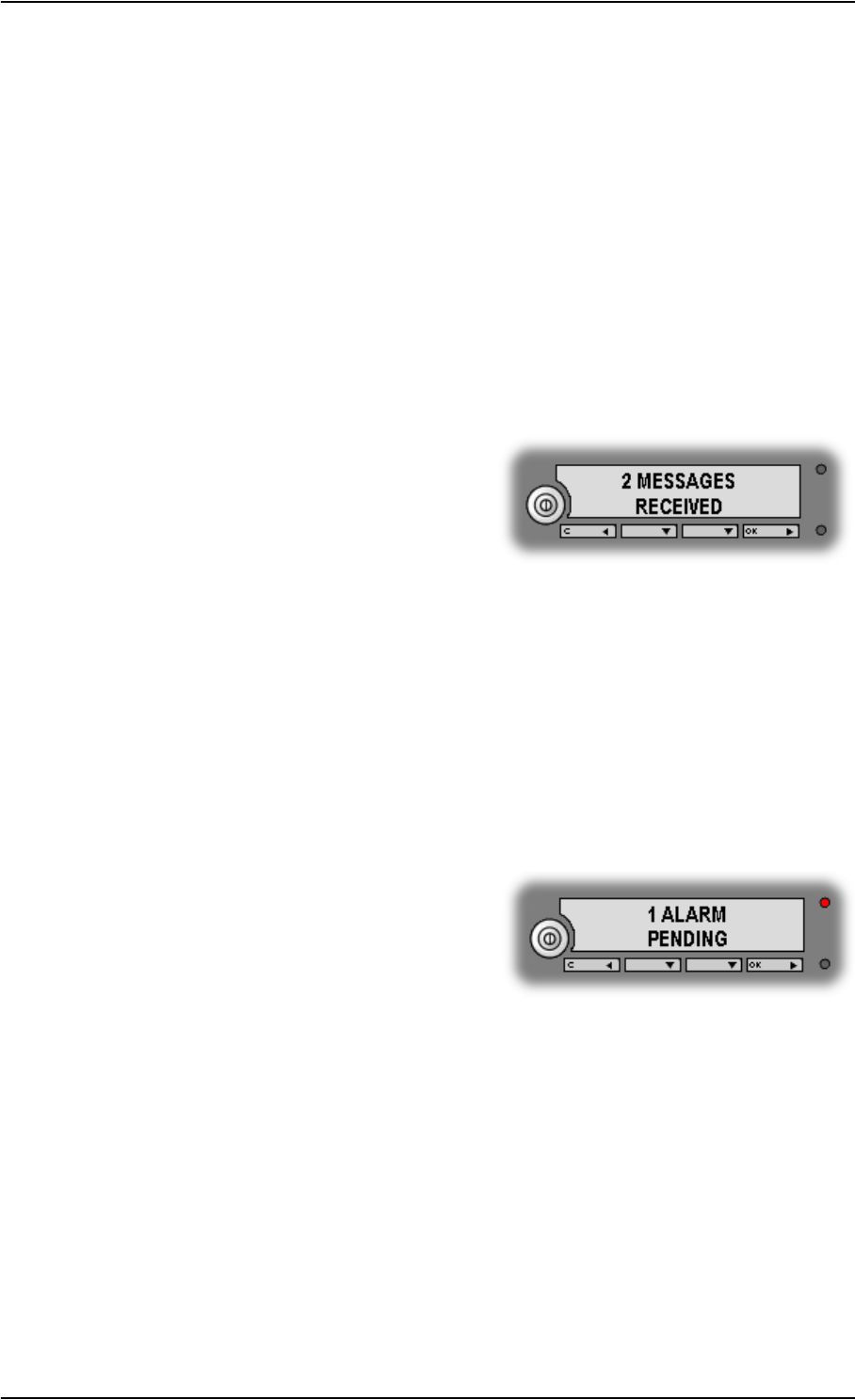
Chapter 3: Using the display and keypad
98-122988-DraftB6 45
Dynamic information in the display
Types of display information
Text in the display can be:
• Information of received messages.
• Alarms.
•Status information.
•Request for action.
Received messages
When messages arrive in your EXPLORER™ 700,
the display indicates the number of new messages
that have arrived, and the red message indicator is
flashing.
The messages can be SMS messages or notification of voice mail.
If the message is an SMS message, you can go directly to the message list by pressing OK.
If the message is information of voice mail, you can press OK or C to go back to the Main screen.
The red message indicator will keep flashing until you have collected your voice mail.
To hear your voice mail, call the voice mail service number provided by your Airtime Provider.
To see the voice mail service number, select
PROPERTIES > VOICE MAIL NUMBER
Alarms
When alarms are issued in your EXPLORER™ 700,
the display indicates the number of new alarms,
and the red message indicator is flashing.
For further information, see Display of alarm
messages on page 146.
All alarms are logged in the alarm log. For information on the alarm log, see Alarm log on
page 152.
To view explanations for the alarms that may appear in the display, refer to List of alarms on
page 147.

Chapter 3: Using the display and keypad
98-122988-DraftB6 46
Status information
Status information in the display is normally shown in the lower line of the Main screen.
Examples of status information are: READY, REGISTERING and DATA ACTIVE.
Displaying ongoing transmission
When a call or data session is in progress, the display shows DATA ACTIVE in the Main screen.
Request for action
A request for action, if it is not an alarm, is shown in the lower line of the display. This could be
e.g. POINT NOW? or INSERT SIM.
When the text is a question, press OK to accept.
What’s next?
This chapter has explained how to navigate in the display menu system and how to use it for basic
setup of the EXPLORER™ 700.
The following chapter, Using the interfaces, explains in detail how to set up and use each interface
of the EXPLORER™ 700.
WARNING! When the EXPLORER™ 700 is powered on, stay clear of the antenna
front! The antenna emits radio frequency energy, not only when the display shows
DATA ACTIVE. Always keep a minimum distance of 1 m from the antenna front.

98-122988-DraftB6 In this chapter 47
Chapter 4
Using the interfaces 4
In this chapter
This chapter describes how to use the interfaces of the EXPLORER™ 700. For each connection type
it describes how to connect cables and the necessary setup to establish a connection.
It does not describe advanced configuration of interfaces. For this type of information, refer to the
“Configuring…” sections for the data interfaces in Chapter 5, Using the web interface.
General
Tools for setup and use
Overview
The display and keypad can be used for simple setup, but for enhanced use and for configuration
of interfaces, you need to connect a computer (PC, laptop or similar).
With a computer and a browser, you can use the following to set up the EXPLORER™ 700:
• The built-in web interface of the EXPLORER™ 700
•The BGAN LaunchPad
The web interface of the EXPLORER™ 700
The web interface is a built-in web server for setting up and controlling the EXPLORER™ 700,
using a connected computer with a browser. For information on how to use the web interface, see
Using the web interface on page 80.
The BGAN LaunchPad
BGAN LaunchPad from Inmarsat is a computer application for setting up terminals in the BGAN
system. A CD-ROM with the LaunchPad is included in the delivery. For information on how to use
the LaunchPad, refer to the user guide provided with the LaunchPad.

Chapter 4: Using the interfaces
98-122988-DraftB6 General 48
Services and interfaces
A variety of services can be accessed from different interfaces on the EXPLORER™ 700.
The following table shows the possible combinations of services and interfaces, and which types of
equipment can be used.
Service
Interface on the EXPLORER™ 700
Phone/
Fax Bluetooth USB LAN WLAN ISDN Display/
Keypad
Circuit Switched Connection
3.1 kHz
Audio
Analog
telephone
Bluetooth
handset
ISDN
telephone
G3 Fax
machine
G4 fax
machine
Standard
Voice
Analog
telephone
Bluetooth
handset
ISDN
telephone
Data
Computer
with
analog
modem
Computer Computer
(64 kbps
UDI)
Computer
with ISDN
modem
Packet Switched Connection
Data
multi-user
Computer Computer Computer
Data
single-
user
Computer Computer Computer Computer
SMS
Computer Computer Computer Computer Computer
with ISDN
modem
View only

Chapter 4: Using the interfaces
98-122988-DraftB6 General 49
Enabling or disabling an interface
Overview
By default, all interfaces are enabled. However, you can disable the LAN interface, the ISDN
interface, the WLAN interface, the Bluetooth interface and/or the Phone/Fax interface in order to
minimize the power consumption.
Using display and keypad
To enable or disable an interface using the display and keypad, do as follows:
1. Enter the menu system.
From the Main screen, press S or T.
2. Select SETTINGS > INTERFACES.
3. Select the interface you want to enable or disable.
4. Select ON to enable or OFF to disable.
Using web interface
To enable or disable an interface using the web interface, do as follows:
1. Connect a computer. Refer to the relevant section in this chapter, e.g. Connecting to the LAN
interface on page 67.
2. Access the web interface.
For further information, see The web interface on page 80.
3. From the left navigation pane in the web interface, select
SETTINGS > Interfaces.
4. Select Enabled or Disabled next to the relevant interface.
Note The USB interface cannot be disabled; it is always enabled.

Chapter 4: Using the interfaces
98-122988-DraftB6 Bluetooth pairing 50
Bluetooth pairing
What is pairing?
Bluetooth Pairing happens when two Bluetooth enabled devices agree to communicate with one
another. When this happens, the two devices exchange passkeys and join a pair. The pairing
process only takes place the first time the two devices are connected. Once the two devices have
established a pair, they automatically accept communication when one device recognizes the
other device.
Pairing devices in which you can enter a passkey
This section describes how to pair devices in which you can enter a passkey.
For information on pairing devices with a fixed passkey from your EXPLORER™ 700, see Pairing
Bluetooth devices from the web interface on page 115.
The following procedure presupposes that the EXPLORER™ 700 is configured to be visible to other
Bluetooth devices, and that the Bluetooth interface is turned on. For information on configuration,
see Configuring the Bluetooth interface on page 113.
Do as follows to pair the devices:
1. Start up the EXPLORER™ 700.
For further information, see Getting started on page 12.
2. Turn on Bluetooth on your Bluetooth device and place it close to the EXPLORER™ 700.
3. On your Bluetooth device, search for new devices and select the EXPLORER™ 700 when it is
found.
The default Bluetooth name of the EXPLORER™ 700 is EXPLORER 700.
If there is more than one EXPLORER™ 700 in the list, you can use the MAC address to locate
the correct one. To see the MAC address of your EXPLORER™ 700, enter the display menu
system and select PROPERTIES > TERMINAL > HARDWARE > MAC.
4. On your Bluetooth device, enter the passkey of your EXPLORER™ 700.
The default passkey is the serial number of your EXPLORER™ 700. To see the serial number,
look at the label on the back of your EXPLORER™ 700, or enter the menu system and select
PROPERTIES > TERMINAL > HARDWARE > UNIT SER. NO.
The new device is now paired and ready to communicate with the EXPLORER™ 700.
Note The method for pairing devices may vary depending on your Bluetooth device. Consult
your Bluetooth device documentation for information.
Note Maximum 7 devices can be paired with the EXPLORER™ 700. If you have already paired 7
devices you have to unpair a device before you can pair a new one. For information on
how to unpair devices, see Unpairing devices on page 117.

Chapter 4: Using the interfaces
98-122988-DraftB6 Using a phone or fax machine 51
Using a phone or fax machine
Selecting the call type
Definition
The phone connection can be either a Standard Voice connection or a 3.1 kHz Audio connection.
In the web interface you can set up which type of connection to use by default when you make or
receive a call from the Phone/Fax, ISDN or Bluetooth interface.
When connecting a fax or a modem you must use 3.1 kHz Audio.
Example: If you always have a fax connected to the same Phone/Fax interface you can set this
interface to 3.1 kHz Audio only. This will mean that if an incoming Standard Voice call is received,
this Phone/Fax interface will not ring.
Selecting the default outgoing call type
To select the default call type for outgoing calls, first connect a computer. Refer to the relevant
section in this chapter, e.g. Connecting to the LAN interface on page 67.
For information on how to set up the outgoing call types for ISDN, see Configuring the ISDN
interface on page 119.
For the Phone/Fax or Bluetooth interface, do as follows:
1. Access the web interface.
For further information, see The web interface on page 80.
2. Select SETTINGS > Interfaces.
3. Select the relevant Phone/Fax or Bluetooth interface.
4. At Outgoing calls, select Standard or 3.1 kHz Audio.
Up to 7 Bluetooth devices can be connected to the Bluetooth interface. Remember to set the
call type for each handset in the BLUETOOTH VOICE DEVICES list.
Overriding the default outgoing call type
To override the default setting for a specific outgoing call, do as follows:
•To use Standard Voice for the call,
dial 1* before the number.
•To use 3.1 kHz Audio for the call,
dial 2* before the number.

Chapter 4: Using the interfaces
98-122988-DraftB6 Using a phone or fax machine 52
Example: To make a call to Thrane & Thrane in Denmark (+45 39558800), forcing the connection
to use Standard Voice, dial 1* 0045 39558800 followed by # if calling from an analog or ISDN
phone, or off-hook key if calling from a Bluetooth handset.
Phone numbers for incoming 3.1 kHz Audio and Standard Voice
3.1 kHz Audio and Standard Voice have separate phone numbers. This way, a person calling a
phone connected to the EXPLORER™ 700 can select whether to use 3.1 kHz Audio or Standard
Voice, simply by using one of the two phone numbers.
If the Mobile subscriber numbers are available on the SIM card you can look them up, using either
the display menu system or the web interface.
To view the phone numbers for Standard Voice and 3.1 kHz Audio, do one of the following:
• Select PROPERTIES > MOBILE NUMBERS in the display menu system, or
• access the web interface and select PROPERTIES. The numbers are listed in the field Mobile
subscriber numbers. For further information, see The web interface on page 80.
If the numbers are not available in the display menus nor the web interface, refer to your airtime
subscription.
For information on how to make a call to the EXPLORER™ 700, see Making a call to the
EXPLORER™ 700 on page 58.
Selecting the incoming call type
To select which call types are accepted for an incoming call, first connect a computer. Refer to the
relevant section in this chapter, e.g. Connecting to the LAN interface on page 67.
For information on how to set up the incoming call types for ISDN, see Configuring the ISDN
interface on page 119.
For the Phone/Fax or Bluetooth interface, do as follows:
1. Access the web interface.
For further information, see The web interface on page 80.
2. Select SETTINGS > Interfaces.
3. Select the relevant Phone/Fax or Bluetooth interface.
4. At Incoming Calls, check Standard or 3.1 kHz Audio or both. For Bluetooth, remember to set
the call type for each handset in the BLUETOOTH VOICE DEVICES list.
If the call type used for a call to the EXPLORER™ 700 is not selected in the web interface, the
connected phone will not ring.
Note This will not change the default call type, only the type used for the ongoing call.
Note The call type you are using must be selected in the web interface (refer to the next
section).

Chapter 4: Using the interfaces
98-122988-DraftB6 Using a phone or fax machine 53
Connecting an analog phone or a fax machine
Before connecting to the Phone/Fax interface
To connect a phone or a fax machine to one of the Phone/Fax connectors, you need an analog
telephone cable with an RJ-11 connector. For specifications and pin-out, refer to Phone interface,
2-port on page 156.
Connecting to the Phone/Fax interface
Do as follows:
1. Connect the cable to your phone or fax machine.
2. Connect the other end of the
cable to one of the Phone/Fax
connectors on the
EXPLORER™ 700.
3. Power up the EXPLORER™ 700 and point the antenna as described in Pointing the antenna on
page 24.
4. Check the connection by making a phone call or sending a fax.
See Making or receiving a phone call with the EXPLORER™ 700 on page 57 or Sending or
receiving a fax message on page 63.
If connection fails, check that the interface is enabled in the EXPLORER™ 700.
If the analog phone icon is not present in the display Main screen and in the Home window of the
web interface, the interface is disabled.
See Enabling or disabling an interface on page 49.
If the interface is enabled, but connection fails, refer to the Troubleshooting Guide on page 140.
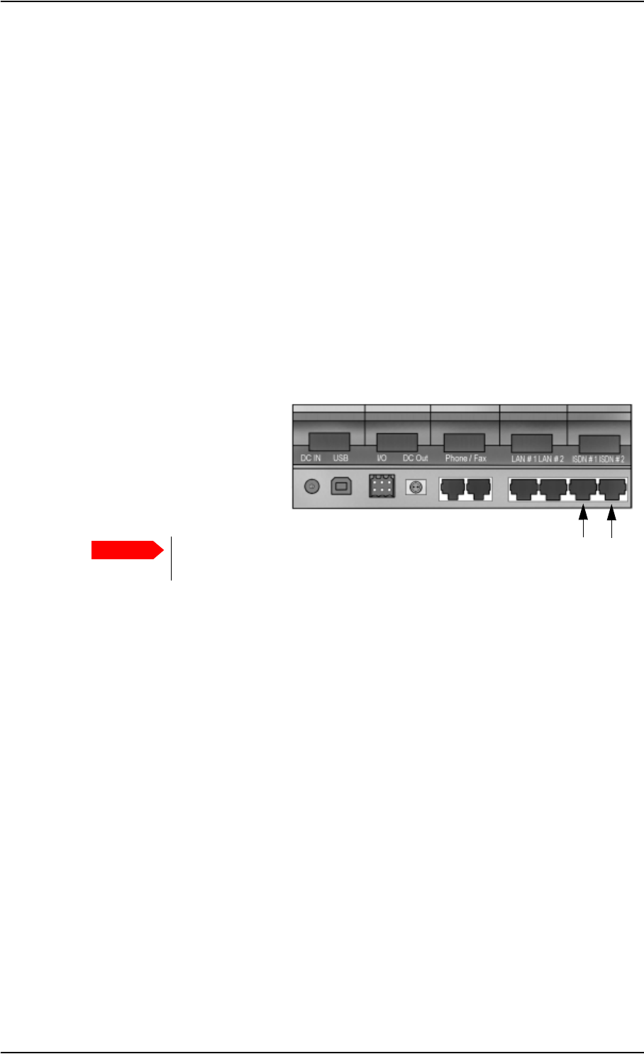
Chapter 4: Using the interfaces
98-122988-DraftB6 Using a phone or fax machine 54
Connecting an ISDN phone or a G4 fax machine
Before connecting to the ISDN interface
To connect a phone or a fax machine to one of the ISDN connectors, you need an ISDN cable with
an ISDN connector. For specifications and pin-out, refer to ISDN interface, 2-port on page 157.
Connecting to the ISDN interface
The ISDN interface supports connection of up to 8 devices per ISDN interface. However, if you are
going to connect more than one device per interface, the devices must be self-powered. The ISDN
interface can supply maximum 1 W.
The Core network presently only supports one 64 kbps ISDN channel per subscription.
Do as follows:
1. Connect the ISDN cable to your phone or fax machine.
2. Connect the other end of the
cable to one of the ISDN
connectors on the
EXPLORER™ 700.
3. Power up the EXPLORER™ 700 and point the antenna as described in Pointing the antenna on
page 24.
4. Check the connection by making a phone call or sending a fax.
See Making or receiving a phone call with the EXPLORER™ 700 on page 57 or Sending or
receiving a fax message on page 63.
If connection fails, check that the interface is enabled in the EXPLORER™ 700.
If the ISDN icon is not present in the display Main screen and in the Home window of the web
interface, the interface is disabled.
See Enabling or disabling an interface on page 49.
If the interface is enabled, but connection fails, refer to the Troubleshooting Guide on page 141.
Important The ISDN interface and the LAN interface use the same connector type. Be
careful not to connect to the wrong interface.

Chapter 4: Using the interfaces
98-122988-DraftB6 Using a phone or fax machine 55
Connecting a Bluetooth handset
Before connecting a Bluetooth handset
To use a Bluetooth handset with the EXPLORER™ 700, you first have to pair the two devices.
For information on pairing devices, see Bluetooth pairing on page 50.
The Bluetooth handset must be placed within a maximum distance of 100 m from the
EXPLORER™ 700. Note that this is the maximum distance in open air; the actual maximum
distance may be shorter, depending on the environment. In an office environment, you should be
able to establish a connection across the adjoining 2-3 rooms.
Connecting a paired Bluetooth handset
This section does not describe configuration of the Bluetooth interface. For information on
configuration, see Configuring the Bluetooth interface on page 113.
If the devices are already paired, do as follows to connect:
1. Power up the handset and the EXPLORER™ 700.
2. Place the handset close to the EXPLORER™ 700.
3. Turn on Bluetooth on your device.
The Bluetooth connection should now be established, and you are ready to make a call.
If connection fails, check that the interface is enabled in the EXPLORER™ 700.
If the Bluetooth icon is not present in the display Main screen and in the Home window of the web
interface, the interface is disabled.
See Enabling or disabling an interface on page 49.
If the interface is enabled, but connection fails, refer to the Troubleshooting Guide on page 142.
For information on how to make and receive calls, see Making or receiving a phone call with the
EXPLORER™ 700 on page 57.
Note The Bluetooth and WLAN interfaces may interfere with each other if they are both active.
For optimum performance, do not use Bluetooth and WLAN simultaneously, or use
WLAN mode 802.11a (5 GHz) if possible.
Note Maximum 7 devices, including voice and data devices, can be connected at the same
time.

Chapter 4: Using the interfaces
98-122988-DraftB6 Using a phone or fax machine 56
Entering the SIM PIN using a phone
Entering the PIN
If you have a phone connected to the EXPLORER™ 700, you can use it to enter the PIN at start up,
as an alternative to the keypad.
When the EXPLORER™ 700 is waiting for a PIN, you will hear 2 beeps — pause — 2 beeps — etc. in
your phone.
You simply dial the PIN the same way you would dial a phone number:
•For an analog or ISDN phone, take the phone off hook and dial <PIN> followed by #. When
you hear a “busy” tone or a dialing tone, the PIN has been accepted and you can put the
phone back on hook.
•For a Bluetooth handset, dial <PIN> and press off hook key. When you hear a “busy” tone or a
dialing tone, the PIN has been accepted and you can press the on hook key.
Wrong PIN
If, instead of the busy tone or dialing tone, you continue to hear 2 beeps — pause — 2 beeps — etc., it
means the PIN was wrong. Check that you have the correct PIN and try again.
If a wrong PIN has been entered three times, you will hear 3 beeps — pause — 3 beeps — etc. This
means you have to enter the PUK (PIN Unblocking Key) provided with your SIM card.
After entering the PUK, you must enter a new PIN of your own choice (4 to 8 digits long).
Dial the following:
<PUK> * <New PIN> * <New PIN> followed by # or off-hook key.
Example: If the PUK is 87654321 and the new PIN is 1234, dial
87654321 * 1234 * 1234 followed by # or off-hook key.
If you enter 10 wrong PUKs, the SIM card will no longer be functional. Contact your Airtime
Provider for a new SIM card.

Chapter 4: Using the interfaces
98-122988-DraftB6 Using a phone or fax machine 57
Making or receiving a phone call with the EXPLORER™ 700
Analog phone, ISDN phone or Bluetooth handset
First connect your phone to the relevant interface. For further information, see Before connecting
to the Phone/Fax interface on page 53, Before connecting to the ISDN interface on page 54, or, for
the Bluetooth handset, Pairing devices in which you can enter a passkey on page 50.
Making a call
You have two methods for making a call:
•Short Dial. If the number is in the phone book of the EXPLORER™ 700, you can use the Short
Dial number, which is found in the first column of the phone book in the web interface. See
Short dial on page 90.
Simply dial 0 <Short Dial> followed by # or off-hook key.
Example: To call entry number 4 in the phone book,
dial 04 followed by # or off-hook key.
•Manual Dial. To make a call, dial
00 <country code> <phone number> followed by # or off-hook key.
Example: To call Thrane & Thrane in Denmark (+45 39558800) from an analog or ISDN
phone, dial 00 45 39558800 #
If there was an error establishing the connection, the web interface and the display of the
EXPLORER™ 700 show an error message. Refer to the Troubleshooting Guide on page 140.
Receiving a call
To be able to receive a call, the phone must be connected to the relevant interface on the
EXPLORER™ 700.
By default, all devices connected to the Phone/Fax interface, the ISDN interface or the Bluetooth
interface will ring when one of the mobile subscriber numbers is called. Note, however, that this
depends on the call type settings. Refer to Selecting the incoming call type on page 52.
Information of missed calls is stored in the call log of the EXPLORER™ 700. You can view the call
log with the display menu system or the web interface. See Calls menu on page 38 or Viewing the
lists of calls on page 92.
Note There are different methods for activating a call, depending on the type of phone:
•Analog phone or ISDN phone: Dial # after the number.
•Bluetooth handset: Press the off-hook key after the number.

Chapter 4: Using the interfaces
98-122988-DraftB6 Using a phone or fax machine 58
Making a call to the EXPLORER™ 700
To make a call to a phone connected to the EXPLORER™ 700, dial
+870 <Mobile subscriber number>
•+ is the prefix used in front of the country code for international calls. This is 00 when calling
from countries in Europe and from many other countries.
•Mobile subscriber number. If the mobile subscriber numbers are available on the SIM card,
you can look them up using the display menu system or the web interface.
•Display menu system:
Enter the menu system and select PROPERTIES > MOBILE NUMBERS.
•web interface:
If a computer is connected, access the web interface, select PROPERTIES and locate the
Mobile subscriber numbers section. For further information on the web interface, see The
web interface on page 80.
If the mobile subscriber numbers are not available in the display menu system nor the web
interface, refer to your airtime subscription.
Dialing functions
Overview
There are a number of dialing functions available in the EXPLORER™ 700.
The following list shows the allocated special-purpose numbers for the EXPLORER™ 700.
Note There are two Voice numbers, one for 3.1 kHz Audio and one for Standard Voice.
Number Function
0 * followed by # or off-hook key Redial last called number on this interface.
00 * followed by # or off-hook key Redial last answered call on this interface.
Note: If the last answered number is an unlisted
number, you will not be allowed to dial back.
0 followed by one of the numbers 1—199
and # or off-hook key
Short dial phone numbers in phone book.

Chapter 4: Using the interfaces
98-122988-DraftB6 Using a phone or fax machine 59
Apart from the numbers above, the EXPLORER™ 700 uses the following dialing prefixes:
•1* before the phone number will force the connection to use Standard Voice.
•2* before the phone number will force the connection to use 3.1 kHz Audio.
•#31# before the phone number will hide the callers phone number to the recipient.
•*31# before the phone number will show the callers phone number to the recipient where it
would otherwise be hidden, e.g. because the number is an ex-directory number.
•R is used during a call to indicate that the following key-presses should activate a
supplementary services function. The supplementary services functions supported by the
EXPLORER™ 700 are described in the subsequent sections.
Making local phone calls
You can make local calls between phones connected to the EXPLORER™ 700.
Local phone numbers always start with 0.
For an overview of the numbers, see Overview on page 58.
To make a local call, dial
<local number> followed by # or off-hook key.
Up to 7 Bluetooth handsets can be connected at the same time, but only one call can be active on
the Bluetooth interface.
0200 followed by # or off-hook key Local call broadcast to all Bluetooth handsets.
All connected Bluetooth handsets will ring. The
first handset that answers, takes the call.
0 followed by one of the numbers
201—207 and # or off-hook key
Local call to Bluetooth handset.
0300 followed by # or off-hook key Local call broadcast to both analog phones.
0 followed by one of the numbers
301—302 and # or off-hook key
Local call to analog phone.
0400 followed by # or off-hook key Local call broadcast to all ISDN phones.
0 followed by one of the numbers
401—408 and # or off-hook key
Local call to ISDN phone on port 1.
0 followed by one of the numbers
411—418 and # or off-hook key
Local call to ISDN phone on port 2.
0900 followed by # or off-hook key Local call broadcast to all handsets.
Number Function
Note You cannot make local calls between two Bluetooth handsets through the
EXPLORER™ 700. You can only make local calls between an analog or ISDN phone and a
Bluetooth handset, or between an analog phone and an ISDN phone.

Chapter 4: Using the interfaces
98-122988-DraftB6 Using a phone or fax machine 60
You can look up the local Bluetooth phone numbers in the display or in the web interface as
follows:
•Display
Enter the menu system and select PROPERTIES > BLUETOOTH DEVICES. The list
shows all accepted Bluetooth devices with local number and Bluetooth name.
•web interface
Access the web interface and select
SETTINGS > Interfaces > Bluetooth > Paired Devices.
The paired voice devices are listed with their local phone numbers.
Local numbers of analog phones and ISDN phones are assigned according to the table in
Overview on page 58. Note that if you are using local numbers for ISDN devices, the numbers
must be programmed in the devices.

Chapter 4: Using the interfaces
98-122988-DraftB6 Using a phone or fax machine 61
Handling waiting calls
During a call, if a second party attempts to make contact with you, you will hear a Call Waiting
indication. The Call Waiting indication is two beeps and a pause of 3 seconds, then two beeps
again etc. If no action is taken, the waiting call is released after a time out period.
When you receive a Call Waiting indication, you have the following options:
Holding a call
During a call, you may place the initial call on hold while another call is made.
Note The phone must have an R key to be able to use these functions.
The EXPLORER™ Bluetooth Handset uses a softkey in stead of the R key.
If you want to: Do as follows:
Clear the current call,
and accept the waiting call.
Press R 1 #, within the time out period.
Hold the current call,
and accept the waiting call.
Press R 2 #, within the time out period.
Ignore the waiting call. Take no action.
Reject the waiting call. Press R 0 #, within the time out period.
Note The phone must have an R key to be able to use these functions.
The EXPLORER™ Bluetooth Handset uses a softkey in stead of the R key.
If you want to: Do as follows:
Place a call on hold. Press R 2 #.
Place the existing call on hold and establish a
new call.
Press R and dial the second phone number
followed by #.
Shuttle between the two calls. Press R 2 #
(irrespective of whether the second call was
acquired using Call Hold or acceptance of Call
Waiting.)
Clear the held call, if no waiting call exists. Press R 0 #.
Clear an active call and return to the held call. Press R 1 #.
Note that this is only possible if no waiting
call exists.

Chapter 4: Using the interfaces
98-122988-DraftB6 Using a phone or fax machine 62
Transferring a call
When you receive a call, you can transfer this call to another phone or headset connected to the
EXPLORER™ 700.
To transfer the incoming call to another phone or headset, do as follows:
1. Press R 4 * <local number> #.
The phone or headset with the local number you dialed starts to ring.
If your phone and the recipient’s phone or headset are both Bluetooth devices, your phone is
now disconnected. When the call is answered, a connection is established between the initial
caller and the new recipient.
2. If only one or none of the devices are Bluetooth devices, you have two options.
• Hang up. The phone or headset you transferred the call to continues to ring. When the call
is answered, a connection is established between the initial caller and the new recipient.
• Do not hang up. When the new recipient answers, you can have a conversation before
hanging up. When you hang up, the call is handed over to the initial caller.
Note The phone must have an R key to be able to use these functions.
The EXPLORER™ Bluetooth Handset uses a softkey in stead of the R key.

Chapter 4: Using the interfaces
98-122988-DraftB6 Using a phone or fax machine 63
Sending or receiving a fax message
Handling delays
When sending or receiving fax messages over satellite, both fax units must be capable of handling
longer delays without timing out. Some fax machines have an Overseas mode, which enables the
unit to handle the long delays.
Sending a fax message
The fax machine must be connected to the Phone/Fax interface or the ISDN interface of the
EXPLORER™ 700. Refer to Before connecting to the Phone/Fax interface on page 53 or Before
connecting to the ISDN interface on page 54.
3.1 kHz Audio must be used for an analog fax machine. Refer to Selecting the default outgoing call
type on page 51.
UDI must be used for an ISDN fax machine, Refer to Configuring the ISDN interface on page 119.
To send a fax from a fax machine connected to the EXPLORER™ 700, dial
00 <country code> <phone number> #
Example: To send a fax to Thrane & Thrane in Denmark
(+45 39558888), dial 00 45 39558888 #
Receiving a fax message
An analogue fax machine connected to the EXPLORER™ 700 can only receive a fax with 3.1 kHz
Audio. Refer to Selecting the incoming call type on page 52.
An ISDN fax machine connected to the EXPLORER™ 700 can only receive a fax with UDI.
Make sure the fax is sent to the 3.1 kHz Audio phone number and that 3.1 kHz Audio or UDI is
enabled for the relevant interface.
Note If the default setting in the web interface is not 3.1 kHz Audio, you can dial 2 * before the
number, to force the connection to use 3.1 kHz Audio. For further information, see
Selecting the default outgoing call type on page 51.

Chapter 4: Using the interfaces
98-122988-DraftB6 Using a computer 64
Using a computer
Choosing an interface for data connection
The EXPLORER™ 700 has five types of interface for data connection: LAN, USB, ISDN, WLAN and
Bluetooth.
The following table shows some characteristics of each interface, to help you choose the right
interface for your application.
Interface Power
Consumption Amount of Setup Range
LAN High None
(or very little)
Up to 100 m of cable
USB Low Some setup necessary Up to 5 m of cable
ISDN Medium Some setup necessary Up to 100 m of cable
WLAN High Some setup necessary Wireless connection.
Up to 100 m depending on the
transmitter in the computer and on
the transmission conditions.
Bluetooth Medium Can be complicated,
depending on
operating system.
Wireless connection.
Up to 100 m depending on the
transmitter in the computer and on
the transmission conditions.

Chapter 4: Using the interfaces
98-122988-DraftB6 Using a computer 65
Standard or Streaming data
Definition
The BGAN network supports different classes of data connection to the Internet. The main classes
are Standard data and Streaming data.
• Using a Standard data connection, several users can share the data connection
simultaneously. This type of connection is ideal for TCP/IP traffic such as e-mail, file transfer,
and Internet and intranet access.
The user pays for the amount of data sent and received.
• Using a Streaming data connection, you get an exclusive, high-priority connection, ensuring
seamless transfer of data. This type of connection is ideal for time critical applications like live
video over IP.
The user pays for the duration of the connection (per minute charge).
You can set up various types of connection using the Profiles and a Traffic Flow Template. For
further information, see Using Profiles on page 127 and Using a Traffic Flow Template on
page 130.
Setting up and activating a Streaming connection
By default, any data connection on the EXPLORER™ 700 is a Standard data connection.
If you want to set up a Streaming connection, select a Streaming Profile when setting up your data
interface. See the “Configuring…” section for your interface in Chapter 5, Using the web interface.
Before starting a Streaming session on the LAN interface, make sure you have set up the
Streaming Profile for the LAN interface.
To start or stop a Streaming session on the LAN interface, do as follows:
1. Access the web interface.
2. Go to the Home window and locate the field STREAMING PROFILES ON LAN.
3. Click the Start or Stop link of the relevant Streaming Profile.
Note For optimum performance it is important that you select the right traffic class when
defining Profiles for your connection.
Note When running a Streaming session you are charged for the time you are connected.
A started Streaming session will stay active until you stop it.
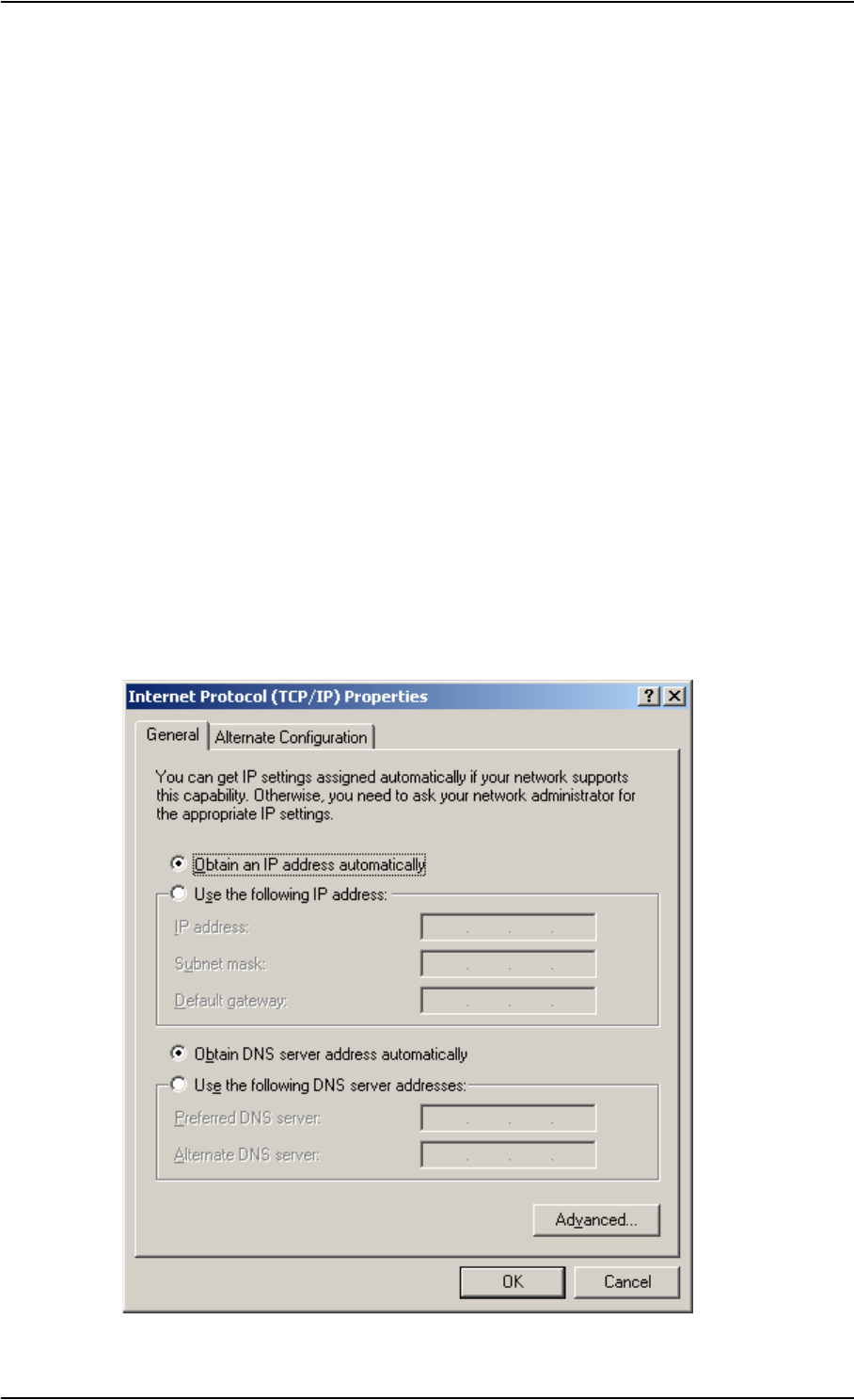
Chapter 4: Using the interfaces
98-122988-DraftB6 Using a computer 66
Using the LAN interface
Before connecting to the LAN interface
The LAN interface on the EXPLORER™ 700 comprises two connectors. If the two LAN connectors
are used simultaneously, the EXPLORER™ 700 should be in Router mode. Refer to Configuring the
LAN interface on page 107.
To connect to the LAN (Local Area Network) interface, use a shielded cable mounted with an RJ-45
connector.
For specifications, refer to LAN interface, 2-port on page 158.
For the LAN interface to work without any further setup, the computer must be set up to obtain an
IP address and a DNS server address automatically.
To check these settings on your computer, do as follows (For Windows XP):
1. Select Connect To > Show All Connections from the Start menu.
2. Double-click Local Area Connection.
3. Click Properties
4. Select Internet Protocol (TCP/IP) from the list and click Properties.
Make sure both fields are set to obtain an address automatically.
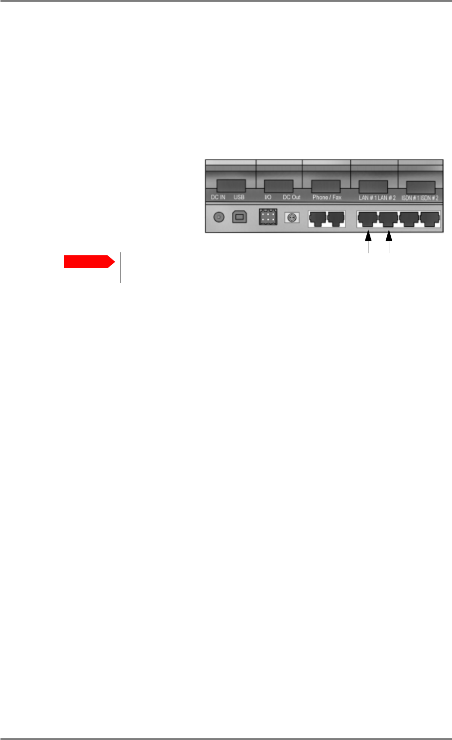
Chapter 4: Using the interfaces
98-122988-DraftB6 Using a computer 67
Connecting to the LAN interface
This section does not describe configuration of the LAN interface. For information on
configuration, see Configuring the LAN interface on page 107.
To connect to the LAN interface, do as follows:
1. Connect the LAN cable to the network interface of your computer.
A suitable cable is provided with your EXPLORER™ 700.
2. Connect the other end of the
cable to one of the LAN
connectors on the
EXPLORER™ 700.
3. Power up the EXPLORER™ 700 and point the antenna as described in Pointing the antenna on
page 24.
After pointing, the connection is automatically established. By default, the connection is a
Standard data connection.
4. Check the connection, e.g. by starting your Internet Browser.
If connection fails, check that the interface is enabled in the EXPLORER™ 700. If the LAN icon is
not present in the display Main screen and in the Home window of the web interface, the interface
is disabled. See Enabling or disabling an interface on page 49.
If connection still fails, refer to the Troubleshooting Guide on page 142.
Important The ISDN interface and the LAN interface use the same connector type. Be
careful not to connect to the wrong interface.

Chapter 4: Using the interfaces
98-122988-DraftB6 Using a computer 68
Using the WLAN interface
Before connecting
The computer should be placed within a maximum distance of 100 m from the EXPLORER™ 700.
Note that this is the maximum distance in open air; the actual maximum distance may be shorter,
depending on the environment. In an office environment, you should be able to establish a
connection across the adjoining 2-3 rooms.
Connecting to the WLAN interface
This section does not describe configuration of the WLAN interface. For information on
configuration, see Configuring the WLAN interface on page 110.
Before you can use the WLAN interface, you have to enter the country code in the
EXPLORER™ 700. For further information, see Configuring the WLAN interface on page 110.
To connect to the WLAN interface, do as follows:
1. Power up the EXPLORER™ 700 and point the antenna.
2. Power up your computer and place it close to the EXPLORER™ 700.
3. Select the EXPLORER™ 700 WLAN access point on your computer.
The default name is EXPLORER 700.
4. Start your Internet browser or E-mail program.
If connection fails, check that the interface is enabled in the EXPLORER™ 700.
If the WLAN icon is not present in the display Main screen and in the Home window of the web
interface, the interface is disabled. See Enabling or disabling an interface on page 49. If the
interface is enabled but connection fails, refer to the Troubleshooting Guide on page 143.
Note The Bluetooth and WLAN interfaces may interfere with each other if they are both active.
For optimum performance, do not use Bluetooth and WLAN simultaneously, or use
WLAN mode 802.11a (5 GHz) if possible.
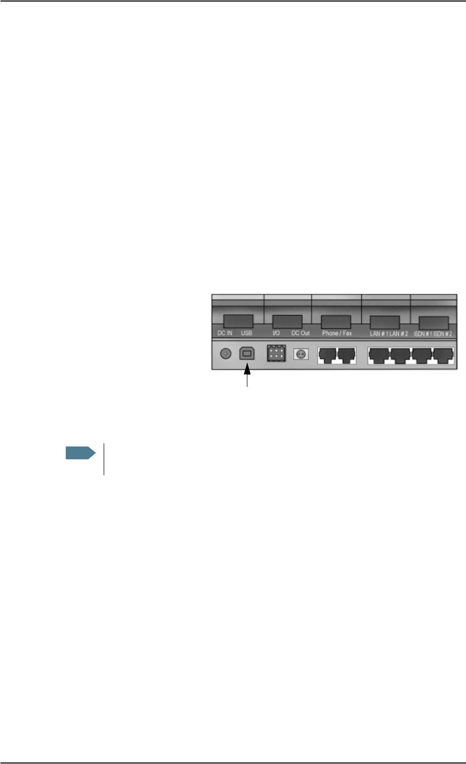
Chapter 4: Using the interfaces
98-122988-DraftB6 Using a computer 69
Using the USB interface
Before connecting to the USB interface
To connect to the USB (Universal Serial Bus) interface, use a USB cable mounted with a USB type
B connector. A suitable cable is provided with your EXPLORER™ 700. For specifications, refer to
USB interface on page 159.
First time setup of USB
If it is the first time you connect your computer to the EXPLORER™ 700 using the USB interface, or
you have exchanged the EXPLORER™ 700 with another EXPLORER™ 700, you must install a driver
as follows:
1. Power up your computer.
2. Connect the USB cable to the USB port of your computer.
3. Connect the other end of the
cable to the USB connector on
the EXPLORER™ 700.
4. Power up the EXPLORER™ 700 as described in Getting started on page 12.
5. Your computer should now automatically discover that new hardware is connected.
6. On Windows XP, the New Hardware Wizard will start automatically. Go through the wizard as
follows:
7. In the New Hardware Wizard, select No, not this time when you are asked if Windows can
search for software.
8. Click Next.
9. Insert the Thrane & Thrane CD-ROM provided with your EXPLORER™ 700 into the CD-ROM
drive of your computer.
10. Select Install the software automatically and click Next.
11. If you get a warning that the software has not passed Windows logo testing, you can safely
click Continue Anyway.
12. Click Finish when the installation is complete.
Note The following description is for Windows XP. If you are using a different operating
system, the procedure may be different.
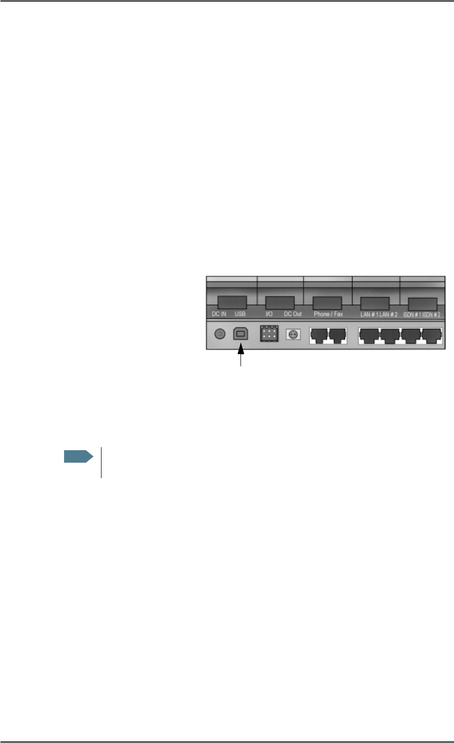
Chapter 4: Using the interfaces
98-122988-DraftB6 Using a computer 70
When you finish the wizard, the Thrane & Thrane EXPLORER™ USB driver is installed.
13. Create a dial-up connection as described in Using 64 kbps UDI (ISDN) through the USB
interface on page 70.
Connecting to the USB interface
This section does not describe configuration of the USB interface. For information on
configuration, see Configuring the USB interface on page 105.
If you are connecting your computer to the USB interface for the first time, see First time setup of
USB on page 69.
To connect to the USB interface, do as follows:
1. Power up your computer.
2. Connect the USB cable to the USB port of your computer.
3. Connect the other end of the
cable to the USB connector on
the EXPLORER™ 700.
4. Power up the EXPLORER™ 700 and point the antenna as described in Getting started on
page 12.
5. To enable communication on the USB interface, open your dial-up connection as described in
the following steps.
6. In Windows XP, select Connect To from the Start menu.
7. Select the dial-up connection created for this USB connection.
8. Click Dial and wait for the connection to be established. Then start your Internet browser or
mail program.
If connection fails, refer to the Troubleshooting Guide on page 144.
Using 64 kbps UDI (ISDN) through the USB interface
You can communicate using ISDN through the USB interface of the EXPLORER™ 700, provided that
your Internet Service Provider (ISP) supports Unrestricted Digital Information (UDI) and that it is
included in your subscription.
Note The following description is for Windows XP. If you are using a different operating
system, the procedure may be different.

Chapter 4: Using the interfaces
98-122988-DraftB6 Using a computer 71
The necessary setup is very limited, so you can very quickly establish a live connection. Note
however, that you are charged for the time you are connected (per minute rate).
Do as follows:
1. Make sure 64 kbps UDI is included in your subscription.
2. From your Airtime Provider, acquire the ISP phone number, User name and Password to
access the 64 kbps UDI service.
3. If you have not yet installed the Thrane & Thrane EXPLORER™ USB driver from the Thrane &
Thrane CD, install it as described in First time setup of USB on page 69.
4. Connect and create a dial-up connection as described in Using 64 kbps UDI (ISDN) through
the USB interface on page 70, with the following exceptions:
• When you are asked for a phone number, type in the ISP phone number.
• When you are asked for User name and password, type in the User name and Password
provided by your ISP.
5. To enable communication, simply open your 64 kbps UDI dial-up connection and click Dial.
You now have a 64 kbps UDI connection to the Internet.
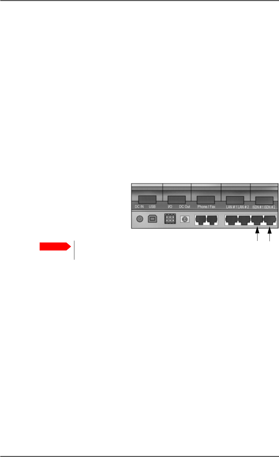
Chapter 4: Using the interfaces
98-122988-DraftB6 Using a computer 72
Using a computer with ISDN
Before connecting
The ISDN interface on the EXPLORER™ 700 comprises two connectors and supports connection of
up to 8 devices simultaneously. However, the Core network presently only supports one 64 kbps
ISDN channel per subscription.
To connect to the ISDN interface, use an ISDN cable with an ISDN connector. For specifications,
refer to ISDN interface, 2-port on page 157.
Connecting a computer to the ISDN interface
This section does not describe configuration of the ISDN interface. For information on
configuration, see Configuring the ISDN interface on page 119.
To connect to the ISDN interface, do as follows:
1. Connect your computer to your ISDN modem.
2. Connect the ISDN cable between
your ISDN modem and one of the
ISDN connectors on the
EXPLORER™ 700.
3. Power up the EXPLORER™ 700 and point the antenna as described in Getting started on
page 12.
4. On your computer, activate your dial-up connection.
5. Check the connection, e.g. by starting your Internet Browser.
If connection fails, check that the interface is enabled in the EXPLORER™ 700. If the ISDN icon is
not present in the display Main screen and in the Home window of the web interface, the interface
is disabled. See Enabling or disabling an interface on page 49.
If connection still fails, refer to the Troubleshooting Guide on page 141.
Important The ISDN interface and the LAN interface use the same connector type. Be
careful not to connect to the wrong interface.

Chapter 4: Using the interfaces
98-122988-DraftB6 Using a computer 73
Using a computer with Bluetooth
Before connecting a computer to the Bluetooth interface
The EXPLORER™ 700 supports various Bluetooth profiles. Remember to activate/install the
profile(s) you are going to use on your computer.
For a list of supported Bluetooth profiles, see Bluetooth interface on page 161.
The computer should be placed within a maximum distance of 100 m from the EXPLORER™ 700.
Note that this is the maximum distance in open air; the actual maximum distance may be shorter,
depending on the environment. In an office environment, you should be able to establish a
connection across the adjoining 2-3 rooms.
If the two devices have not been connected before, you need to pair the devices. For further
information, see the section Bluetooth pairing.
Connecting a computer to the Bluetooth interface
This section does not describe configuration of the Bluetooth interface. For information on
configuration, see Configuring the Bluetooth interface on page 113.
If the devices are already paired, do as follows to connect:
1. Place the computer close to the EXPLORER™ 700.
2. Power up the EXPLORER™ 700 and point the antenna.
3. Power up your computer.
4. Turn on Bluetooth on your computer.
If the devices are paired, the Bluetooth connection should now be established.
Note that if your Bluetooth connection is defined as a dial-up connection, you have to open
the dial-up connection before you can access the Internet or the web interface. See
Connecting to the USB interface on page 70.
If connection fails, check that the interface is enabled in the EXPLORER™ 700.
If the Bluetooth icon is not present in the display Main screen and in the Home window of the web
interface, the interface is disabled. See Enabling or disabling an interface on page 49. If the
interface is enabled but connection fails, refer to the Troubleshooting Guide on page 145.
Note The procedure may vary depending on the Bluetooth interface in your computer. Consult
your Bluetooth manual for details.
Note The Bluetooth and WLAN interfaces may interfere with each other if they are both active.
For optimum performance, do not use Bluetooth and WLAN simultaneously, or use
WLAN mode 802.11a (5 GHz) if possible.
Note Max. 7 devices, including voice and data devices, can be connected simultaneously.
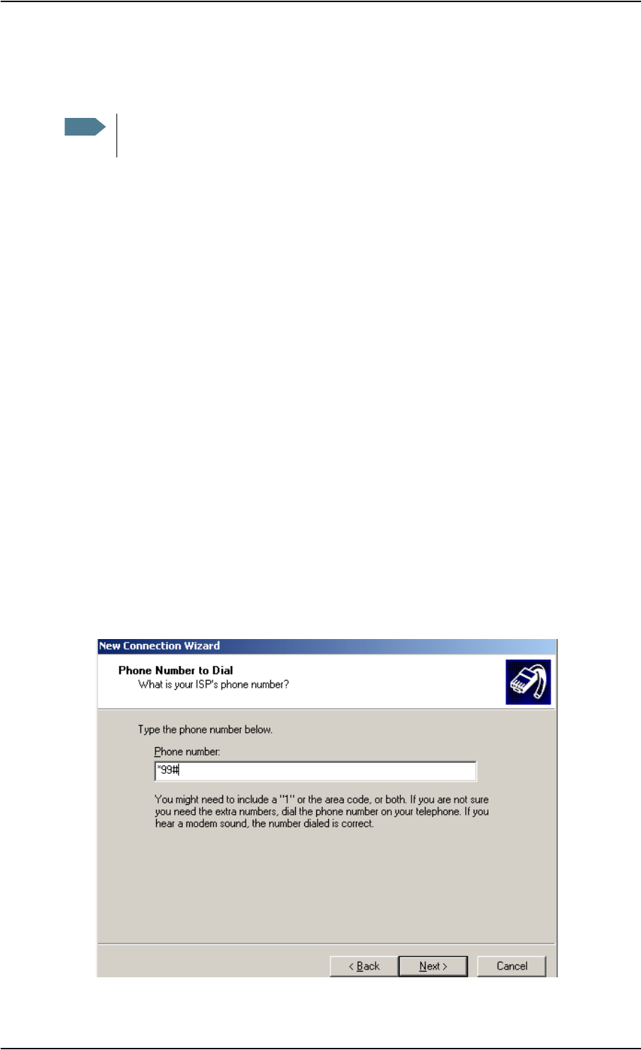
Chapter 4: Using the interfaces
98-122988-DraftB6 Using a computer 74
Creating a dial-up connection
Do as follows:
1. Start up your computer and the EXPLORER™ 700.
2. Connect the USB cable between your computer and the USB connector on your
EXPLORER™ 700, or place your paired Bluetooth computer close to the EXPLORER™ 700. For
information on Bluetooth, see Using a computer with Bluetooth on page 73.
3. On your computer, select Connect To from the Start menu.
4. Select Show All Connections.
5. Open the New Connection Wizard and click Next.
6. Select Connect to the Internet and click Next.
7. Select Set up my connection manually and click Next.
8. Select Connect using a dial-up modem and click Next.
If other modems are installed, you must select the Thrane & Thrane EXPLORER™ USB driver,
or the Bluetooth driver, from a list of modems.
9. In the ISP Name field, type a name for your connection and click Next.
10. When you are asked for a phone number, type:
*98# if you want a Standard data connection to the Internet and/or the web interface, or *99#
if you are going to connect only to the web interface of the EXPLORER™ 700.
To dial up using a specific Profile, type *98*<CID>#.
Note The following description is for Windows XP. If you are using a different operating
system, the procedure may be different.

Chapter 4: Using the interfaces
98-122988-DraftB6 Using a computer 75
To find the <CID> number, access the web interface, select SETTINGS > Interfaces > USB (or
Bluetooth) and locate the Profile CIDs section at the bottom of the window.
For further information, see Configuring the USB interface on page 105 or
Configuring the Bluetooth interface on page 113.
11. Click Next.
12. If you are using UDI, enter the User name and Password and click Next.
If you are not using UDI, simply click Next without entering User name and Password.
See Using 64 kbps UDI (ISDN) through the USB interface on page 70.
13. Click Finish.
When you connect to the USB interface, or to the Bluetooth interface using dial-up, you must open
this dial-up connection to access the Internet or the web interface.
To open the dial-up connection (in Windows XP), select Connect To from the Start menu, select
your dial-up connection and click Dial. When the connection is established, you can access the
Internet as usual.
Note You may need to enter User name and Password to access the Internet. If necessary,
enter the User name and Password supplied by your Internet Provider.

Chapter 4: Using the interfaces
98-122988-DraftB6 Additional interfaces 76
Additional interfaces
Using the EXPLORER™ 700 antenna
Before connecting the antenna
You can use the EXPLORER™ 700 with the antenna attached to the transceiver, or you can detach
the antenna from the transceiver and use it as a separate antenna unit.
If you are using the antenna attached to the transceiver, use the short antenna cable to connect
antenna and transceiver.
If you are using the antenna detached from the transceiver, use one of the antenna cables from
Thrane & Thrane, or a cable with the same specifications. For information on available lengths,
see Options and accessories on page 136. For specifications on the antenna interface, refer to
Antenna interface on Transceiver on page 162.
Connecting the antenna
Do as follows:
1. Connect the antenna cable to the connector
on the antenna module.
• If you are going to use the antenna and transceiver attached as one unit, use the short
antenna cable provided with your EXPLORER™ 700.
• If you are going to use the antenna separated from the transceiver, first open the terminal
and gently lift the transceiver out of the antenna frame. Then place the antenna in a
location with a clear view to the satellite and connect the antenna cable.
2. Connect the other end of the cable to the
antenna connector on the transceiver.
You are now ready to power up, enter PIN code and point the antenna of the EXPLORER™ 700.
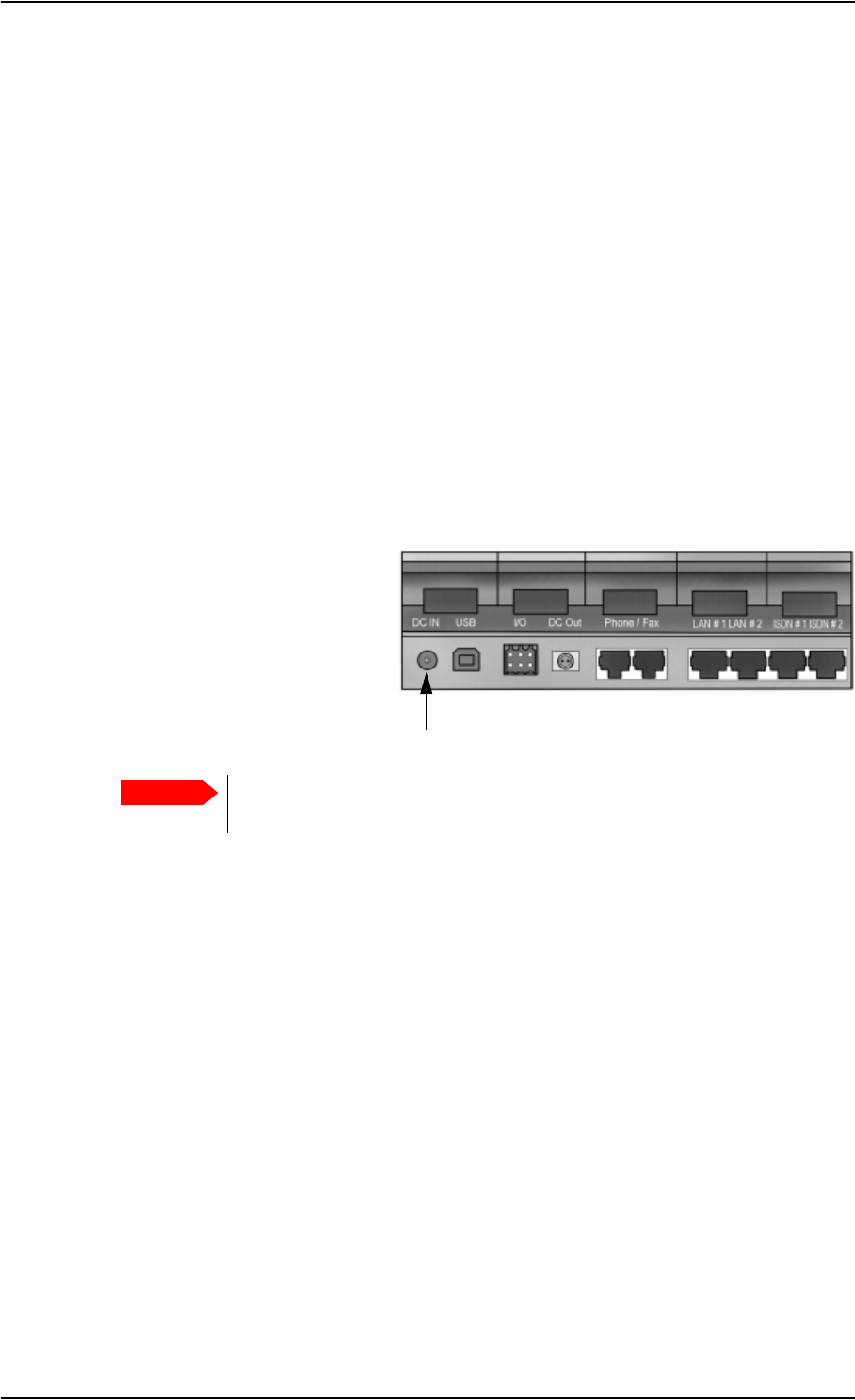
Chapter 4: Using the interfaces
98-122988-DraftB6 Additional interfaces 77
Using a solar panel
Before connecting
The EXPLORER™ 700 battery must be inserted when a solar panel is used. When the solar panel is
connected, it will supply the power to charge the battery of the EXPLORER™ 700.
To connect to the solar panel interface, use a suitable cable matching the output power of your
solar panel. For specifications on the solar panel interface, refer to Solar panel interface on
page 165.
Connecting a solar panel
Do as follows:
1. Make sure the battery is inserted.
2. Connect the cable to your solar panel.
3. Connect the other end of the
cable to the DC in connector on
the EXPLORER™ 700.
4. Point the solar panel directly towards the sun to obtain maximum power.
The battery is now charging.
The indicator left to the display is constantly green as long as the battery is charging. When the
battery is fully recharged, the green indicator is turned off. If the EXPLORER™ 700 is switched on,
the green indicator will be flashing shortly every 2 seconds.
If a charging error occurs, the green indicator on the EXPLORER™ 700 flashes rapidly. See the
Troubleshooting Guide on page 137.
Important Avoid shadows from trees, buildings or similar. Shadows reduce the output
power of the solar panel significantly.
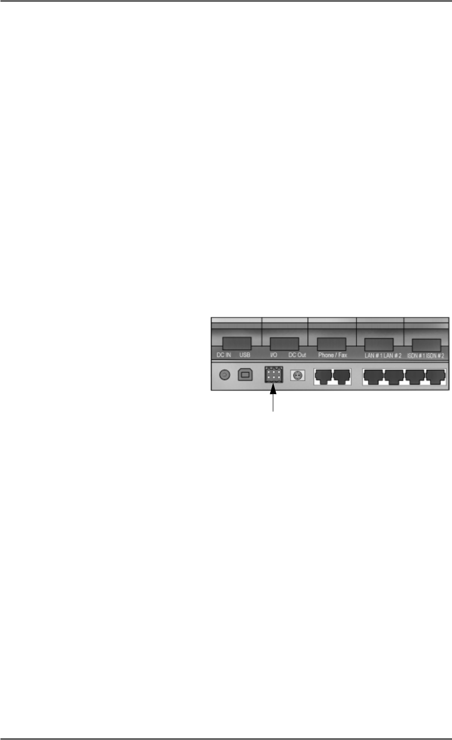
Chapter 4: Using the interfaces
98-122988-DraftB6 Additional interfaces 78
Using the I/O interface
Before connecting
The EXPLORER™ 700 has an Input/Output interface that can be used for control or signaling.
One available function is: To implement a remote switch for switching on the EXPLORER™ 700,
you can connect to I/O pin 1.
For further information on the functions of the I/O interface, contact your distributor.
For specifications on the I/O interface, refer to I/O interface on page 165.
Connecting to the I/O interface
Do as follows:
1. Mount your cable(s) at one end with a connector of the following type:
B2L 3.5/6, TT part no: 31-203302-443, Weidmuller Part no: 1727640000 (black).
2. Connect the other end of the cable(s) to your control or signaling equipment.
3. Connect the end with the newly
mounted connector to the I/O
interface on the
EXPLORER™ 700.
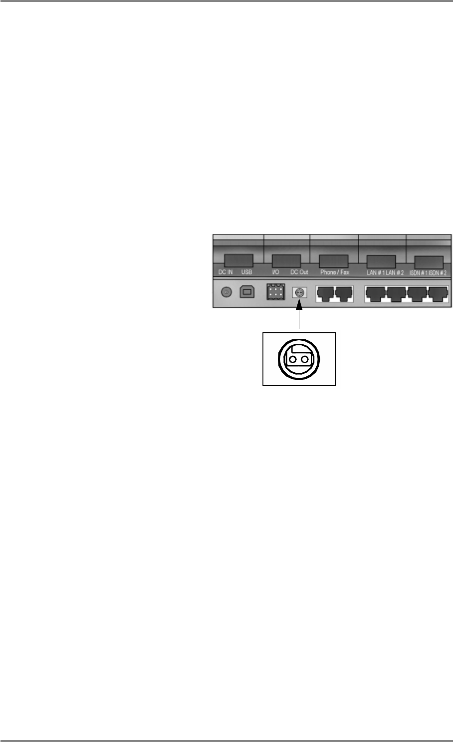
Chapter 4: Using the interfaces
98-122988-DraftB6 What’s next? 79
Using the EXPLORER™ Bluetooth Handset charger
Before connecting to the EXPLORER™ Bluetooth Handset charger interface
If you are using an EXPLORER™ Bluetooth Handset, you can recharge the handset using the DC
charger interface of the EXPLORER™ 700.
Use the charger cable supplied with the EXPLORER™ Bluetooth Handset.
For specifications on the charger interface, see EXPLORER™ Bluetooth Handset charger interface
on page 164.
Connecting to the EXPLORER™ Bluetooth Handset charger interface
Do as follows:
1. Connect the Bluetooth charger
cable to the charging connector
on the EXPLORER™ 700.
Make sure the connector is oriented correctly
in relation to the coding of the plastic insert.
2. Connect the other end of the cable to your
EXPLORER™ Bluetooth Handset.
If the EXPLORER™ 700 battery is inserted or the EXPLORER™ 700 is connected to power, the
battery of the Bluetooth Handset is now recharged.
What’s next?
This chapter has described the basics of how to set up and use each interface.
The following chapter, Using the web interface, describes how to use the built-in web interface for
setting up and using the EXPLORER™ 700.

98-122988-DraftB6 In this chapter 80
Chapter 5
Using the web interface 5
In this chapter
This chapter describes how to use the web interface to operate, set up and configure the
EXPLORER™ 700.
Initial configuration of interfaces is described in the chapter Using the interfaces on page 47.
Introduction
The web interface
What is the web interface?
The web interface is a built-in web server in the EXPLORER™ 700, used for operating, setting up
and configuring the EXPLORER™ 700.
You can access the web interface from a standard Internet browser.
Internet Explorer 6.0, Mozilla Firefox 1.0 and Apple Safari 2.0 have been tested successfully with
the web interface.
You may be able to use other browser versions as well.
Connecting
Connect your computer to the EXPLORER™ 700.
Make sure your computer is set up for the interface you are planning to use for connecting to the
EXPLORER™ 700. You can use LAN, USB, ISDN, WLAN or Bluetooth. See Using the interfaces on
page 47 for details.
To access the web interface, an Internet browser must be installed on the computer.
Important If you are going to use USB or Bluetooth with Dial-up Networking to access only the
web interface and not the Internet, you must use a dial-up connection with the
phone number set to *99#. For further information, see Connecting to the USB
interface on page 70.
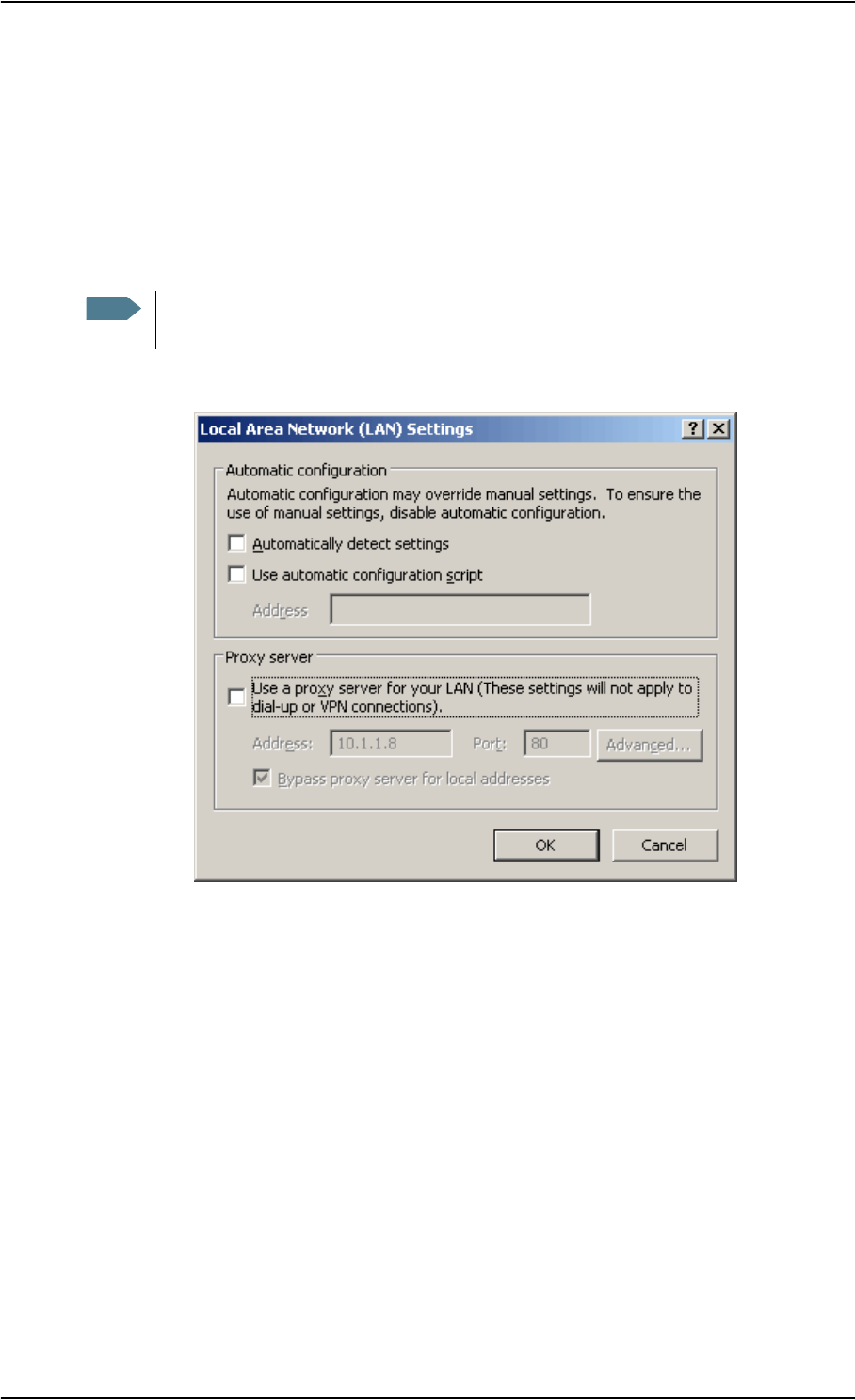
Chapter 5: Using the web interface
98-122988-DraftB6 Introduction 81
Browser settings
If you are connecting your computer using the LAN interface, the Proxy server settings in your
browser must be disabled before accessing the web interface.
Most browsers support disabling of the Proxy server settings for a specific IP address only, so you
can disable Proxy server settings for the web interface only, if you wish. Consult your browser help
for information.
To disable the use of a Proxy server completely, do as follows:
1. In Microsoft Internet Explorer, select Tools > Internet Options > Connections > LAN Settings.
2. Uncheck the box labeled Use a proxy server for your LAN.
3. Click OK.
When the proxy server settings are disabled, close your browser.
You may need to change this setting back on return to your Internet connection.
Note The following description is for Microsoft Internet Explorer. If you are using a different
browser, the procedure may be different.
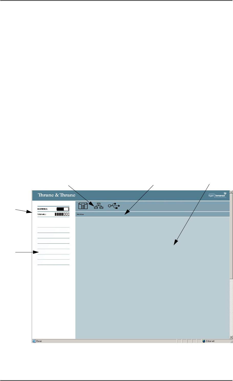
Chapter 5: Using the web interface
98-122988-DraftB6 Introduction 82
Accessing and navigating the web interface
Accessing the web interface
To access the web interface from a connected computer, do as follows:
1. Connect your computer to the EXPLORER™ 700.
For further information, see Using a computer on page 64.
2. Start up the EXPLORER™ 700.
For further information, see Getting started on page 12.
3. Open your browser and enter the IP address of the EXPLORER™ 700.
The standard IP address is 192.168.0.1.
If your EXPLORER™ 700 uses a different IP address, you can look it up by entering the display
menu system of the EXPLORER™ 700 and selecting
PROPERTIES > IP ADDRESS.
Overview of the web interface
The web interface consists of the following sections.
Navigation
Status
Icon Bar Contents Section
Pane
Menu Path
Field
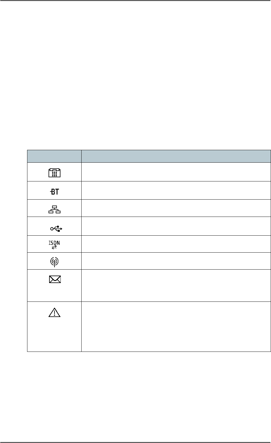
Chapter 5: Using the web interface
98-122988-DraftB6 Introduction 83
•The navigation pane holds the main menu. Clicking an item in the menu opens a submenu in
the navigation pane or a new page in the contents section.
•The status field shows battery status and signal strength.
•The icon bar shows an icon for each interface that is enabled. It also shows icons for new SMS
messages and for active alarms, when relevant. For explanations of the icons, see the next
section, Icons in the icon bar.
•The menu path shows the path through the menu system to the current page shown in the
contents section.
•The contents section shows the page selected in the navigation pane. This section is used for
viewing or changing settings, or for performing actions.
Icons in the icon bar
The following icons may appear in the icon bar in the web interface:
Icon Explanation
Phone/Fax interface is on.
Bluetooth interface is on.
LAN interface is on.
USB interface is on.
ISDN interface is on.
WLAN interface is on.
A new SMS message, or information of Voice mail, has arrived.
Click the icon to see new messages or information of Voice mail. For
further information, see Receiving a message on page 95.
An alarm is pending.
Click the icon to see a list of active alarms. For explanations of the alarm
messages, see List of alarms on page 147.
Note that the alarm icon will remain in the icon bar as long as the cause
of the alarm is still present.

Chapter 5: Using the web interface
98-122988-DraftB6 Introduction 84
Navigating the web interface
•To expand a menu, click the menu in the navigation pane.
•To access status and settings, click the relevant subject in the navigation pane or click the
relevant icon in the icon bar. The status or settings are displayed in the contents section.
•To see the site map, click SITE MAP in the navigation pane. Click on items in the site map to
go directly to the relevant location.
•To return to the Home window from anywhere in the system, click Home, either from the
navigation pane or from the menu path below the icon bar.
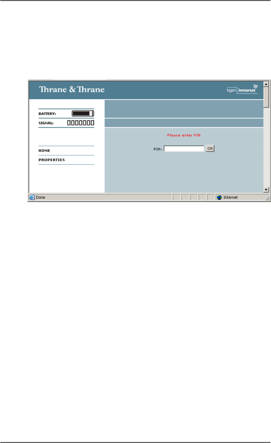
Chapter 5: Using the web interface
98-122988-DraftB6 Introduction 85
Entering the SIM PIN in the web interface
If a computer is connected when you start up the EXPLORER™ 700, and the web interface is
accessed, you can enter the SIM PIN from the web interface.
Until you enter the PIN in the Home window, you can only access the PROPERTIES window and
upload software. Access to all other parts of the web interface requires a PIN.
Type in the PIN and press OK.
If you enter a wrong PIN 3 times you are asked for a PUK (PIN Unblocking Key). For further
information, see Wrong PIN on page 23.
If the PIN has already been entered in the EXPLORER™ 700, or the PIN is disabled e.g. from the
BGAN LaunchPad, the web interface goes directly to the Home window at start-up.
When the correct PIN is entered, the web interface opens the Home window and is ready for use.
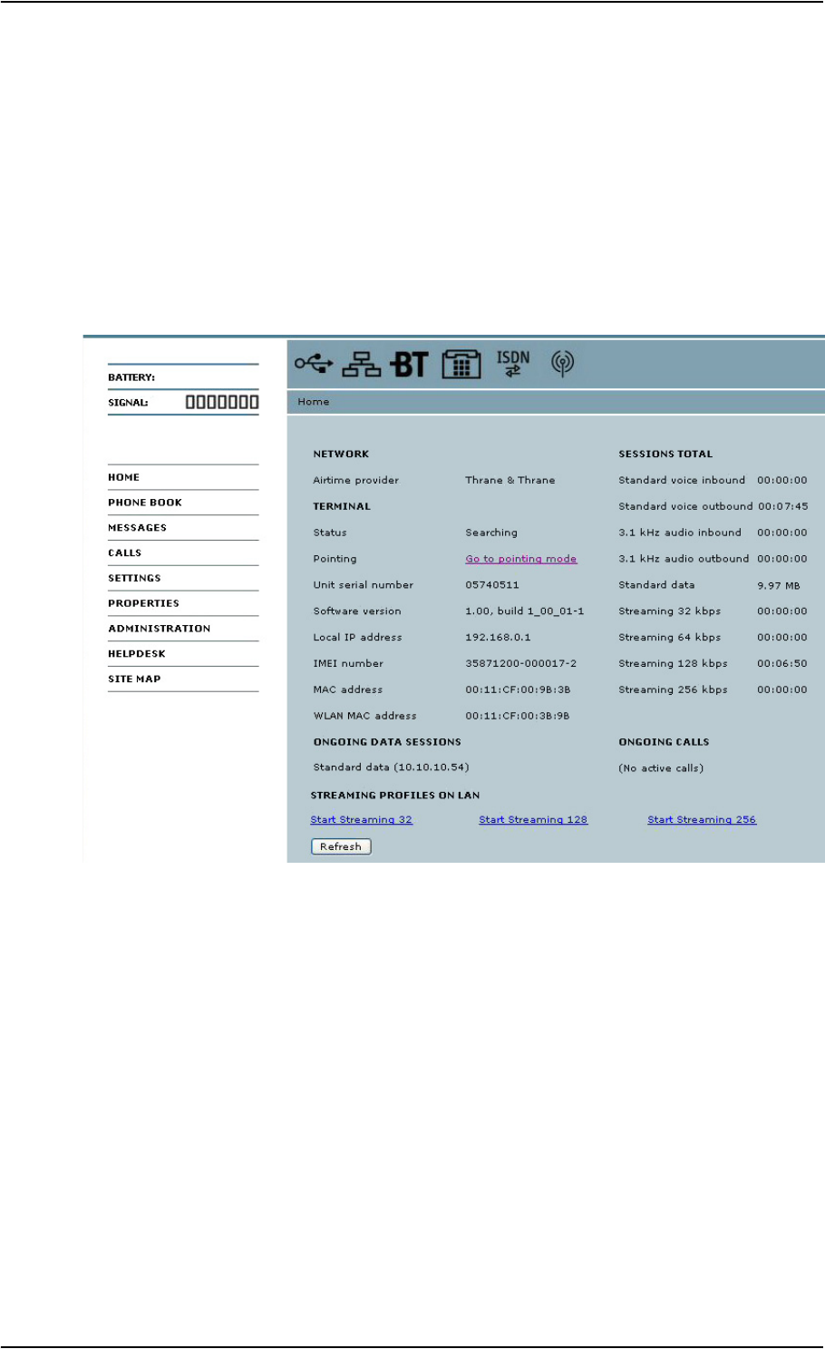
Chapter 5: Using the web interface
98-122988-DraftB6 The Home window 86
The Home window
Overview
The Home window of the web interface contains a “dashboard” for control and inspection of
ongoing communication and for viewing properties of the EXPLORER™ 700.
The NETWORK section shows the name of the Airtime Provider, if this information is available on
the SIM card.

Chapter 5: Using the web interface
98-122988-DraftB6 The Home window 87
Terminal properties
The TERMINAL section of the Home window shows the following:
•Status. The status of the EXPLORER™ 700. This field corresponds largely, but not completely,
to the status information in the display.
Examples of status information are: Ready, Registering and Data active.
•Pointing. If you want to point the antenna, click the link Go to pointing mode. For further
information, see Pointing using web interface on page 88.
•Unit serial number. The serial number of the total unit.
•Software version. The version of the software embedded in the EXPLORER™ 700.
•Local IP address. The local IP address of the EXPLORER™ 700.
•IMEI number. The IMEI number (International Mobile Equipment Identity) of the
EXPLORER™ 700. This is a unique number that identifies your EXPLORER™ 700.
•MAC address for the LAN and Bluetooth interfaces in the EXPLORER™ 700.
•WLAN MAC address for the WLAN interface in the EXPLORER™ 700.
Managing calls and data sessions
Start/stop a Streaming session on the LAN interface
To start or stop a Streaming session, click the relevant link under STREAMING PROFILES ON LAN.
For information on setup of the LAN interface, see Configuring the LAN interface on page 107. For
information on how to set up a Profile, see Using Profiles on page 127.
Viewing information on calls and data sessions
The following sections in the Home window show information on calls and data sessions.
•ONGOING CALLS is a list of calls that are currently active. The list shows the call type and the
time connected for each call.
•ONGOING DATA SESSIONS is a list of data Profiles that are currently active, including the IP
address that is assigned to each PDP context.
•SESSIONS TOTAL lists the totals for each connection. The list shows the time connected for
voice and Streaming data, and MB transferred for Standard data.
Note Before starting a Streaming session, make sure you have set up a Streaming Profile and
activated it for the relevant interface in the SETTINGS > Interfaces > LAN window.

Chapter 5: Using the web interface
98-122988-DraftB6 The Home window 88
Pointing using web interface
Instead of using the display for observing the signal strength you can view and accept the signal
strength in the web interface.
Do as follows:
1. From the TERMINAL section of the Home window in the web interface, click the link Go to
pointing mode. The Pointing window opens, and the EXPLORER™ 700 enters pointing mode.
2. Point the antenna as described in Pointing the antenna on page 24, while observing the
signal strength in the web interface.
3. When you have obtained the highest signal strength you can get, click Accept.
The web interface now returns to the Home window, and the EXPLORER™ 700 tries to establish a
connection and register on the BGAN network.
Note At this point the EXPLORER™ 700 may make a sound. This sound is used for pointing
the antenna. The frequency of the sound increases with the signal strength.
To toggle the pointing sound on/off, press S or Ton the keypad of the
EXPLORER™ 700.
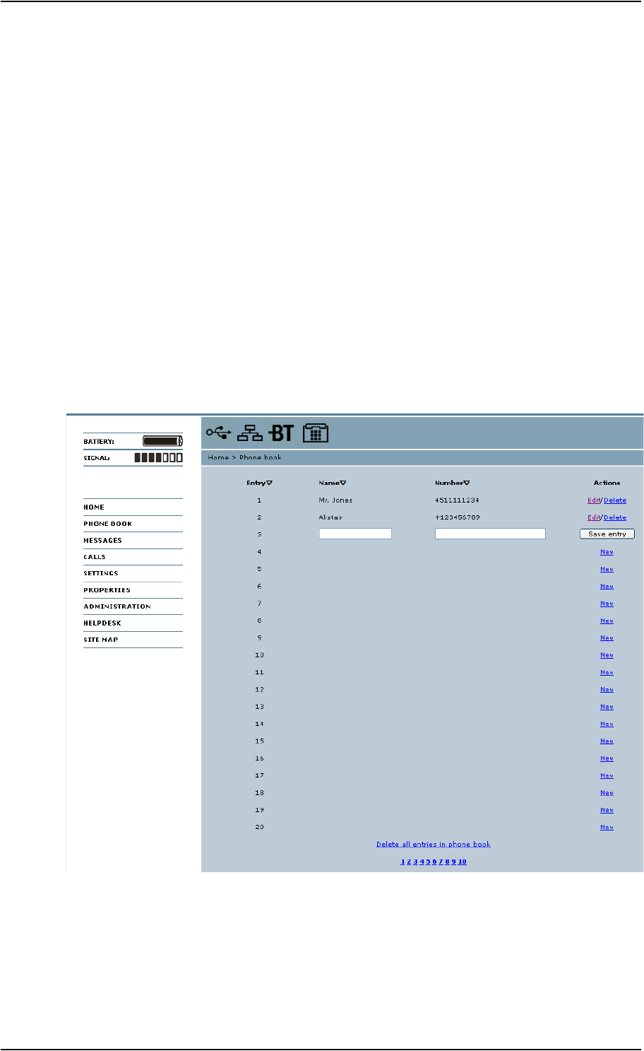
Chapter 5: Using the web interface
98-122988-DraftB6 Using the phone book 89
Using the phone book
General usage
Overview
In the phone book you can:
• Look up phone numbers.
• Look up short dial numbers for easy dialing from an analog or Bluetooth handset.
• Modify or delete existing names and phone numbers, or enter new names and phone
numbers.
Accessing the phone book
To access the phone book, select PHONE BOOK from the left navigation pane.
The phone book shows all entries with entry number, name and phone number. Empty place
holders are also included.
To sort the phone book, click the title of the column you wish to sort by. For example, to sort by the
names in the phone book alphabetically, click on Name in the top row of the phone book.

Chapter 5: Using the web interface
98-122988-DraftB6 Using the phone book 90
The phone book is divided into subpages. To select the subpages you want, click the relevant link
at the bottom of the page.
Short dial
The entry number in the phone book is the Short dial number. When making a call from the
EXPLORER™ 700 you can use this number instead of dialing the entire phone number.
Simply dial 0 <short dial> followed by # or off-hook key.
Example: To call the third entry in the phone book from an analog phone, take the phone off
hook and dial 03 #.
Editing phone book entries
Adding a new entry
To add a new entry, do as follows:
1. In the phone book, locate the empty entry number where you want to add the new phone
number and click New.
2. Type in the name and phone number of the new entry and click Save entry.
The new name and number are now listed at the specified entry number in the phone book.
Modifying an entry in the phone book
To modify an entry, do as follows:
1. In the phone book, click Edit next to the entry you want to modify.
2. Modify the name or number as wanted and click Save entry.
The name and/or number in the selected entry is now replaced with the new information.
Deleting an entry in the phone book
To delete an entry, click Delete next to the entry you want to delete.
Deleting all entries in the phone book
To delete all the entries in the phone book, click Delete all entries in phone book at the bottom of
the PHONE BOOK window.
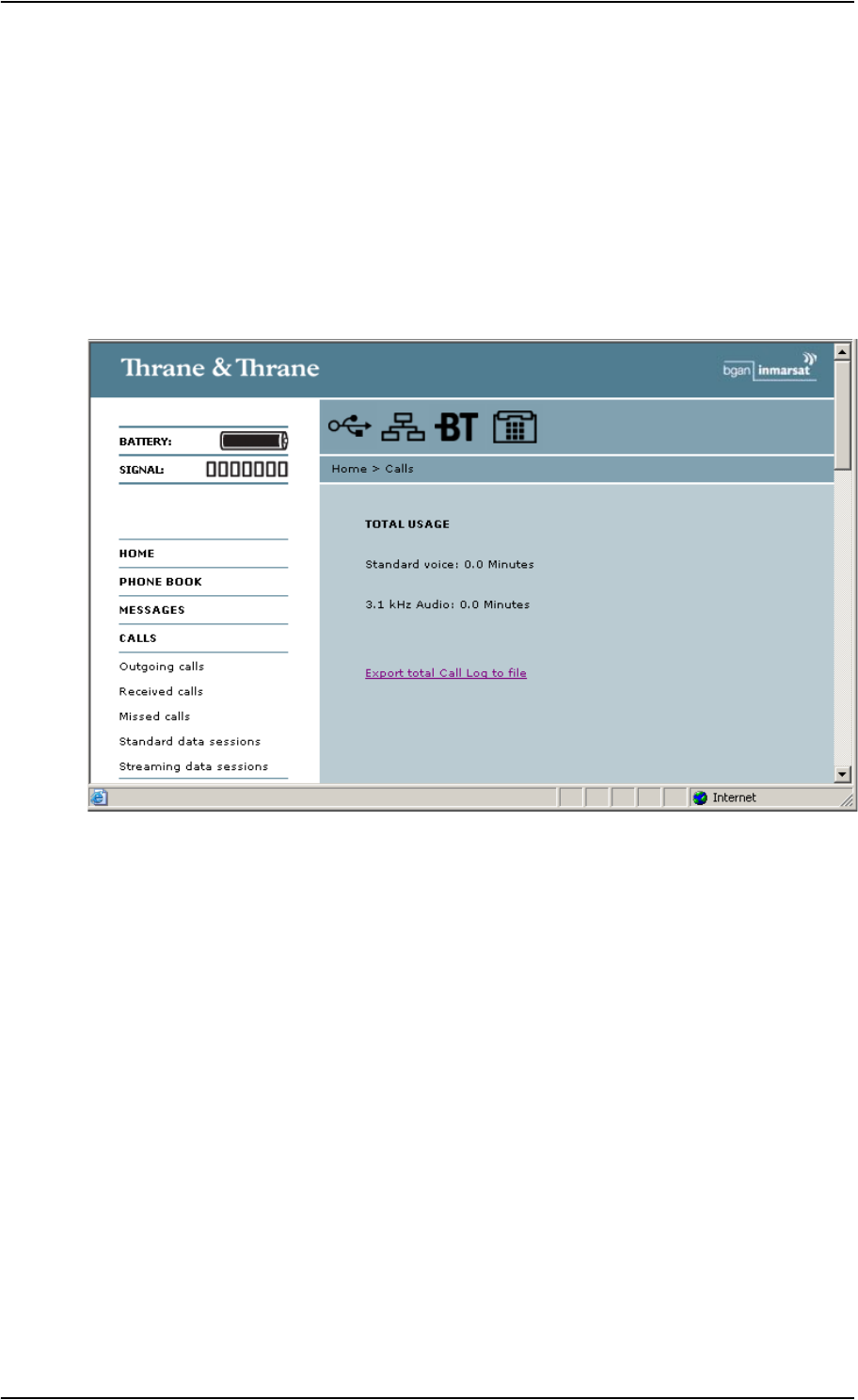
Chapter 5: Using the web interface
98-122988-DraftB6 Using the Call log 91
Using the Call log
Information on total usage
To enter the CALLS window select CALLS from the left navigation pane. The CALLS window
contains information on usage for circuit switched connections. The listed information includes:
• Time connected using Standard Voice and
• time connected using 3.1 kHz Audio.
Exporting the call log
The EXPLORER™ 700 logs all calls and data sessions. For information on how to view the lists of
calls and data sessions, see the next section.
To export the entire call log to a file, do as follows:
1. In the CALLS window, click the link Export total Call Log to file.
2. Browse to the location where you want to save the log.
3. Click OK.

Chapter 5: Using the web interface
98-122988-DraftB6 Using the Call log 92
Viewing the lists of calls
To see information on outgoing, received or missed calls or data sessions, select one of the
following lists from the left navigation pane in the CALLS window:
•Outgoing calls shows the start time, receiving end phone number, duration, type (Standard or
3.1 kHz Audio) and estimated charge of each outgoing call.
•Received calls shows the start time, calling phone number, duration and type (Standard or
3.1 kHz Audio) of each incoming call.
• Missed calls shows the start time, calling phone number and type (Standard or 3.1 kHz Audio)
of each incoming call that was not received.
•Standard data sessions shows the start time, bytes in, bytes out and estimated charge of each
Standard data session.
•Streaming data sessions shows the start time, duration, type (Streaming 32, 64, 128 or
256 kbps) and estimated charge of each Streaming data session.
Date and time is UTC time, received from the satellite.
You can sort each of the lists by clicking the title of the column you wish to sort by.
If a list covers more than one page, you can click the relevant link at the bottom of the page, to go
to another page.
When there are more than 100 calls in the total list, the oldest calls are automatically removed to
make room for new calls.
Note The estimated charge is based on your entries under ADMINISTRATION > Call charges.
Thrane & Thrane does not take responsibility for the correctness of this estimated
charge.
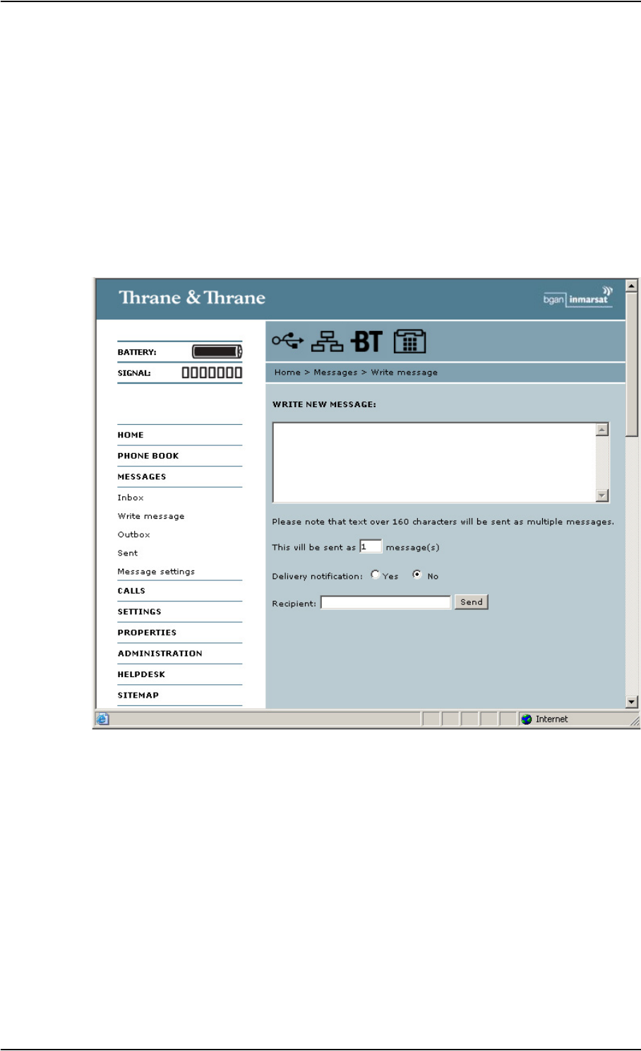
Chapter 5: Using the web interface
98-122988-DraftB6 Handling messages 93
Handling messages
Sending an SMS message from the EXPLORER™ 700
To send an SMS message from the EXPLORER™ 700, do as follows:
1. Click MESSAGES from the left navigation pane.
This window contains new incoming messages.
2. In the left navigation pane, click Write message.
3. Type in the message in the Write new message field.
If the message text is too long for one SMS, the message is sent as two or more SMS
messages. The field below the message field shows the number of SMS messages used to
send the message.
4. Type in the phone number in the Recipient field.
Remember 00 and country code
(e.g. 00 45 to call Denmark or 00 1 to call USA).
5. Select whether or not you want Delivery notification for this SMS message.
If you click Yes, the Status column in the Sent folder will show the status of your message
when it has been sent.

Chapter 5: Using the web interface
98-122988-DraftB6 Handling messages 94
You can set up delivery notification generally for all SMS messages. This setting is used by
default when you send a message. For further information, see Configuring message settings
on page 97.
6. Click Send.
The message is now sent and moved to the Sent folder.
Options for messages in the Outbox
Messages in the Outbox are messages that have not been sent, e.g. because the EXPLORER™ 700
was not online when you attempted to send the messages.
To access the Outbox, click MESSAGES > Outbox from the navigation pane.
You have the following options for messages in the Outbox:
• When the EXPLORER™ 700 is online, click Resend next to the message you want to send.
When the Write message window opens, click Send.
The EXPLORER™ 700 now attempts to send the message again. To make sure the message
has been sent, look in the Sent folder.
• Click Delete next to a message to delete it.
• Click Delete all messages in Outbox to delete all the messages.
Options for messages in the Sent folder
The Sent folder contains SMS messages that have been sent.
To access the Sent folder, select MESSAGES > Sent from the navigation pane.
The Status column shows the status of each message, if you have selected Delivery notification
when sending the message.
From the Sent folder you have the following options:
• Click Resend next to a message you want to send again.
When the Write message window opens, click Send.
The EXPLORER™ 700 now attempts to send the message again. To make sure the message
has been sent, look in the Sent folder. There should now be two copies of the sent message.
• Click Forward next to a message you want to forward.
Important If the EXPLORER™ 700 is not online when you attempt to send a message, the
message is moved to the Outbox in stead of the Sent folder. Messages in the
Outbox are not automatically sent when the EXPLORER™ 700 goes online. For
further information on the Outbox, see the next section, Options for messages
in the Outbox.
To make sure a message has been sent, check that it has been moved to the
Sent folder.
Note The original message remains in the Outbox. When you have succeeded in sending
the message you may want to delete it from the Outbox.

Chapter 5: Using the web interface
98-122988-DraftB6 Handling messages 95
When the Write message window opens, type in the phone number of the new recipient and
click Send.
The EXPLORER™ 700 now attempts to send the message to the new recipient. To make sure
the message has been sent, look in the Sent folder.
• Click Delete next to a message to delete it.
• Click Delete all sent messages to delete all the messages.
Sending an SMS message to the EXPLORER™ 700
You can send an SMS message to the EXPLORER™ 700 e.g. from a mobile phone, using one of the
mobile subscriber numbers for voice. Dial
+870 <Mobile subscriber number>
To see the voice numbers of your EXPLORER™ 700, select PROPERTIES from the web interface or
from the display menu system and view Mobile subscriber numbers. Note, however, that these
numbers are only listed if they are available on the SIM card. Otherwise, refer to the information
included with your airtime subscription.
Receiving a message
If a message has arrived, the icon bar at the top of the web interface shows an unopened
envelope. Click the envelope to see the new message(s).
Otherwise, to see new messages, click MESSAGES from the left navigation pane.
The window shows new incoming messages.
If the message is not an SMS message but information of voice mail, call your voice mail service
number to hear the voice mail.
To find your voice mail service number, select MESSAGES > Message settings from the left
navigation pane and locate the Voice mail service number.
Note that the voice mail number is only shown if it is available on the SIM card. Otherwise, refer to
the information included with your Airtime subscription.
Note There are two Voice numbers, one for 3.1 kHz Audio and one for Standard Voice.
Note The EXPLORER™ 700 does not accept more than 100 incoming messages (including read
and unread messages). If you have received 100 messages, you have to delete some of
them in order to free space for new messages. Otherwise, the new messages are
rejected.

Chapter 5: Using the web interface
98-122988-DraftB6 Handling messages 96
Options for new SMS messages
To see new messages, click MESSAGES from the left navigation pane.
Besides viewing the new messages, you have a number of options for what to do with each
message:
• Click Read to move it to your Inbox containing read messages.
• Click Reply to reply to a message.
Then type in your reply and click Send.
For information on how to include the original message in your reply, see Setting up the
default message options on page 97.
• Click Forward to forward a message to someone.
Then type in the phone number in the Recipient field and click Send.
• If you want to move all the new messages, click Move all new messages to Inbox.
Options for SMS messages in the Inbox
The messages in the Inbox are the incoming messages that have been read and moved from the
list of new messages (refer to the previous section).
From the Inbox, you have the following options:
• Click Reply to reply to a message.
Then type in your reply and click Send.
For information on how to include the original message in your reply, see Setting up the
default message options on page 97.
• Click Forward to forward a message to someone.
Then type in the phone number in the Recipient field and click Send.
• Click Delete to delete the message.
• Click Delete all messages in Inbox to delete all read messages in the Inbox.
Note New messages cannot be deleted until they have been moved to the Inbox.
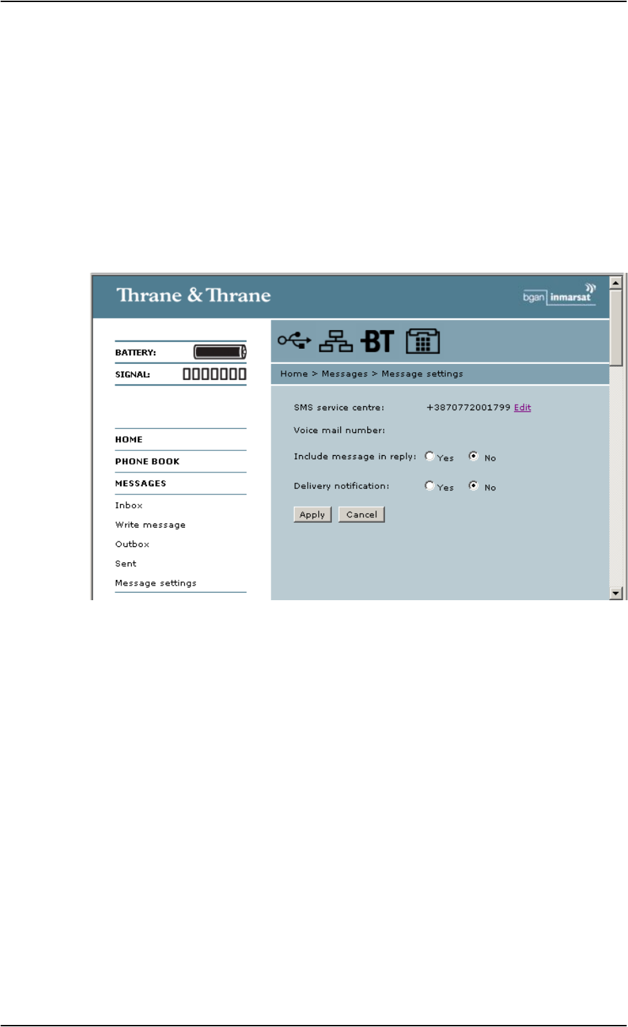
Chapter 5: Using the web interface
98-122988-DraftB6 Handling messages 97
Configuring message settings
Setting up the default message options
You can set up general options for your outgoing messages. These settings apply by default to all
your outgoing messages. Note, however, that you can change the Delivery notification setting for
an individual message. For further information, see Sending an SMS message from the
EXPLORER™ 700 on page 93.
Do as follows:
1. Select MESSAGES > Message settings from the left navigation pane.
2. If you want to include the original message when you reply, select Yes next to Include
message in reply.
3. Select whether or not you want Delivery notification for SMS messages.
If you click Yes, the Status column in the Sent folder will show the status of your message
when it has been sent.
4. Click Apply.

Chapter 5: Using the web interface
98-122988-DraftB6 Handling messages 98
Viewing or changing SMS service center number
The SMS service center number identifies the SMS service center used when sending and
receiving SMS messages. The SMS service center number is stored on the SIM card.
• To see the SMS service center number, select
MESSAGES > Message settings from the left navigation pane.
• To change the number, click Edit next to SMS service center, change the number and click
Save. Then click Apply to apply all changes in the window.
The SMS service center number is provided from your Airtime Provider.
Viewing the Voice mail number
The Voice mail number is the number you call to hear your incoming voice mails.
To see the Voice mail number, select
MESSAGES > Message settings from the left navigation pane.
Note The Voice mail number is only listed if it is available on the SIM card. Otherwise, refer to
the information included with your Airtime subscription.

Chapter 5: Using the web interface
98-122988-DraftB6 Setting up the EXPLORER™ 700 99
Setting up the EXPLORER™ 700
Accessing the EXPLORER™ 700 settings
Select SETTINGS from the left navigation pane. The SETTINGS window contains the local settings of
the EXPLORER™ 700. The next sections describe these settings.
Power up behavior
Pointing at power up
If the EXPLORER™ 700 is placed in a fixed position it may not be necessary to go through the
pointing process every time the EXPLORER™ 700 is powered. You can set up the EXPLORER™ 700
to automatically establish a connection to the BGAN network, if you know that the signal strength
is sufficient.
1. In the Power up section of the SETTINGS window, select whether or not pointing is required at
power up.
• To go through the pointing process every time the EXPLORER™ 700 is powered, select Yes.
• To have the EXPLORER™ 700 automatically register itself on the network every time the
EXPLORER™ 700 is powered, select No.
2. Click Apply.
If you have selected that pointing is not required at power up, the start up procedure will be as
follows:
1. Power up.
2. Enter the PIN. After the PIN is entered, the EXPLORER™ 700 immediately tries to connect to
and register on the BGAN network.
Automatic power up
1. In the Power up section of the SETTINGS window, select whether or not the EXPLORER™ 700
should switch on automatically when external power is applied.
• To have the EXPLORER™ 700 switch on automatically when external power is applied,
select Yes.
• To have the EXPLORER™ 700 switch on only when the power button is pressed, click No.
2. Click Apply.

Chapter 5: Using the web interface
98-122988-DraftB6 Setting up the EXPLORER™ 700 100
Setting the display backlight and contrast
To set the display backlight and contrast, do as follows:
1. In the Backlight section of the SETTINGS window, set the timing.
The Timed period is the period of time the light will stay on after the last key is pressed.
2. Set the level of the backlight with the Set level scroll bar.
3. In the Contrast section, click Yes next to Automatic if you want the contrast to be adjusted
automatically according to the temperature.
The contrast of the display changes with the temperature. The EXPLORER™ 700 can
automatically adjust the contrast to compensate for these variations.
4. If you want to set the contrast manually, set the contrast level with the Set level scroll bar.
5. Click Apply.
Turning audio indicators on or off
The EXPLORER™ 700 has audio indicators for different events or situations.
To enable or disable these audio indicators, do as follows:
1. In the Audio indicators section of the SETTINGS window, turn the audio indicators on or off
using the radio buttons. Each audio indicator is explained below.
2. Click Apply.
The EXPLORER™ 700 has audio indicators for the following events:
•Pointing.
The Pointing sound is used during the pointing process. The frequency increases with the
signal strength, to help you find the maximum signal strength when pointing the antenna.
This setting is a default setting. When the EXPLORER™ 700 is in pointing mode, you can
toggle pointing sound on/off for the current pointing process using S or Ton the keypad of
the EXPLORER™ 700. However, the default setting applies at the next pointing process.
• Messages.
The Message indicator is a sound indicating that a message has arrived.
•Alarm.
The Alarm indicator is a sound indicating that an alarm is issued.
An alarm is issued if the EXPLORER™ 700 detects an error that requires your action.

Chapter 5: Using the web interface
98-122988-DraftB6 Setting up the EXPLORER™ 700 101
Enabling activation of stealth mode
In Stealth mode, the EXPLORER™ 700 operates with no sounds nor lights. However, it is still
possible to operate the EXPLORER™ 700 and the display text is, in most cases, readable.
To enable the use of Stealth mode for the EXPLORER™ 700, do as follows:
1. Select SETTINGS from the left navigation pane.
2. In the Stealth mode section, click Enable.
If you click Disable, the Stealth mode function cannot be activated.
3. Click Apply.
Important Only enable activation of Stealth mode if you are going to use it. If Stealth mode is
activated by mistake, it may be difficult to operate the EXPLORER™ 700.
Note This setting does not activate Stealth mode, it only enables the use of Stealth mode.
To activate Stealth mode, press C+OK on the keypad.
To deactivate Stealth mode and return to normal function, press C+OK again.
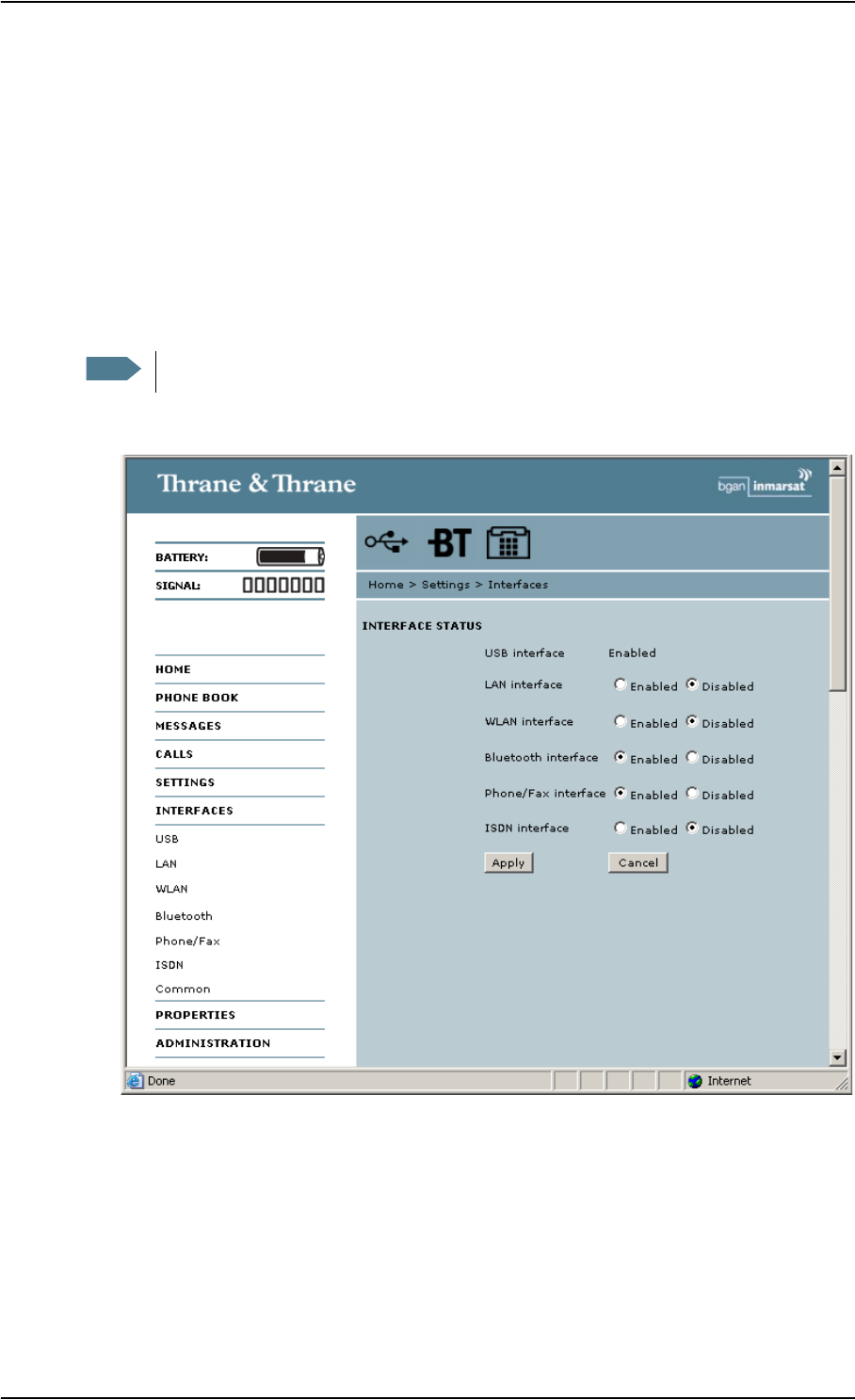
Chapter 5: Using the web interface
98-122988-DraftB6 Setting up the interfaces 102
Setting up the interfaces
Enabling/disabling interfaces
By default, all interfaces are enabled. However, you can disable the LAN interface, the Bluetooth
interface, the ISDN interface, the WLAN interface and/or the Phone/Fax interface in order to
minimize power consumption.
The icons in the Icon bar at the top of the web interface shows interfaces that are enabled. Clicking
an icon brings you to the window where you can set up the interface or enable/disable it.
1. Select SETTINGS > Interfaces from the left navigation pane.
2. In the Interfaces window, select Enabled or Disabled next to the interface you want to
enable/disable.
3. Click Apply.
Note The USB interface cannot be disabled; it is always enabled.

Chapter 5: Using the web interface
98-122988-DraftB6 Setting up the interfaces 103
Description of data settings
Introduction
There are several data parameters that can be set up in the web interface. This section gives an
overview of these parameters.
APN (Access Point Name)
The APN is used by the EXPLORER™ 700 user to establish the connection to the required
destination network. This means that the EXPLORER™ 700 must know the APN in order to be able
to connect to the destination network.
APNs are provided from the Airtime Provider. They may also be defined on the SIM card.
Header compression
The Header of a data packet contains control information belonging to that packet. The
information in the Header can take up a considerable amount of bandwidth. In order to save
bandwidth, you can use Header Compression, meaning you compress the header information,
leaving some of the information out.
You can select whether or not to use Header Compression for your data transmission.
•Header Compression enabled: Recommended for low-noise applications.
If you select Header Compression enabled, you will be using less bandwidth on header
information, leaving more bandwidth for the actual payload.
However, if the environment is noisy, the system will have to retransmit information, and you
may end up using more bandwidth than without Header Compression.
•Header Compression disabled: Recommended in noisy environments.
If Header Compression is disabled, the system will be less sensitive to noise.
Primary and secondary Profiles
A Profile is a collection of Quality of Service (QoS) settings and other settings defining the mode in
which data is transmitted on an interface. For example, a Profile is used to define whether a
connection should be a Standard or Streaming connection.
You can select between a number of predefined Profiles or define your own Profiles for your data
transmission.
In the EXPLORER™ 700, you need an Administrator password to define Profiles and Traffic Flow
Templates.
Note If you have selected more than one Profile (one primary and one or more secondary
Profiles) for an interface, you must define a Traffic Flow Template before you can
establish a valid connection.

Chapter 5: Using the web interface
98-122988-DraftB6 Setting up the interfaces 104
NAT (Network Address Translation)
NAT enables a local-area network to use one set of private IP addresses for internal traffic and an
assigned or static IP address for external traffic. The built-in NAT module in the EXPLORER™ 700
makes all necessary address translations between the local-area traffic and the external traffic.
If more than one user is connected to the LAN interface of the EXPLORER™ 700, it is necessary to
use a switch, as the EXPLORER™ 700 only has one LAN connector. If more than one user is
connected using a switch, you must select Router mode to use the NAT of the EXPLORER™ 700.
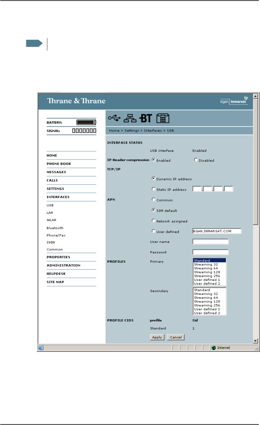
Chapter 5: Using the web interface
98-122988-DraftB6 Setting up the interfaces 105
Configuring the USB interface
For an explanation of each of the data settings, see Description of data settings on page 103.
To configure the USB interface, do as follows:
1. Select SETTINGS > Interfaces > USB.
2. Under TCP/IP, select whether your computer uses a Dynamic IP address or a Static IP address.
If you are using a static IP address, type in the address.
To check this setting on your computer, see the TCP/IP properties of the USB connection on
your computer.
Note The USB interface cannot be turned off; it is always on.

Chapter 5: Using the web interface
98-122988-DraftB6 Setting up the interfaces 106
3. Select the source of the APN.
There are four options for setting the APN. Unless you have special requirements, it is
recommended to use the SIM default, or to set the common APN to SIM default, and then
select Common here. You have the following options:
•Common. The APN is taken from the Common settings defined under
SETTINGS > Interfaces > Common. Refer to Setting a common APN on page 120.
•SIM default. The APN is taken from the SIM card.
•Network assigned. The APN is assigned from the network.
•User defined. Type in the APN. APNs are provided from the Airtime Provider.
4. If your APN uses a password, type in the user name and password provided from the Airtime
Provider.
5. Select the Primary Profile.
Select a Profile from the scroll list. This Profile is used by the USB interface as a first choice,
when possible.
There are 5 predefined Profiles: Standard, Streaming 32 kbps, Streaming 64 kbps, Streaming
128 kbps and Streaming 265 kbps. Additionally, you can define your own custom Profiles.
For further information on Profiles and Traffic Flow Templates, see Using Profiles on page 127
and Using a Traffic Flow Template on page 130.
6. Select the Secondary Profile.
To select more than one secondary Profile, press and hold Ctrl while selecting.
The Context Identifiers (CIDs) for the selected primary and secondary Profiles are listed under
Profile CIDs. You may need these CIDs when you create a dial-up connection. See Using 64
kbps UDI (ISDN) through the USB interface on page 70.
7. Click Apply.
Important If you have selected a Streaming connection as your Primary Profile, the USB
interface will be running a Streaming connection until you select another
Profile or disconnect the interface. However, if you select one or more
Secondary Profiles, you can set up your Traffic Flow Template so that it will only
use the Streaming Profile for certain types of traffic.
Note If you have selected both a Primary and one or more Secondary Profiles you
must define a Traffic Flow Template before you can establish a valid
connection.
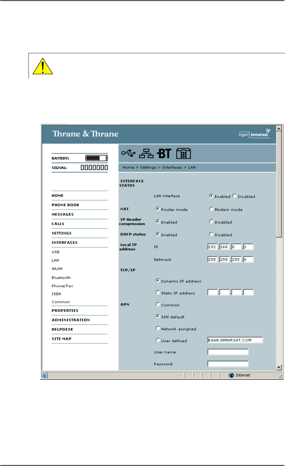
Chapter 5: Using the web interface
98-122988-DraftB6 Setting up the interfaces 107
Configuring the LAN interface
For an explanation of each of the data settings, see Description of data settings on page 103.
All LAN settings, except enabling/disabling the interface, also apply to the WLAN interface.
To configure the LAN interface, do as follows:
1. Select SETTINGS > Interfaces > LAN.
2. Select whether the LAN interface should be Enabled or Disabled.
CAUTION! If you are connected using LAN while changing the settings below,
your changes may affect your current connection.

Chapter 5: Using the web interface
98-122988-DraftB6 Setting up the interfaces 108
3. Under NAT, select whether the EXPLORER™ 700 should run in Router mode or in Modem
mode. Router mode is recommended for most purposes.
Select Router mode if one or more computers are connected using the LAN interface, and the
EXPLORER™ 700 should act as a router. When Router mode is selected, the EXPLORER™ 700
uses the built-in NAT module for making the necessary address translations.
Select Modem mode if
• only one computer is connected to the LAN interface, and the EXPLORER™ 700 should act
as a modem, or
• more than one computer is connected to the LAN interface using an external router.
4. Under IP Header compression, select Enabled or Disabled. For information on this setting, see
Header compression on page 103.
5. Under DHCP status, enable or disable DHCP.
If you select Enabled, the internal DHCP server in the EXPLORER™ 700 is enabled.
6. Under Local IP address, type in the IP address and netmask for your EXPLORER™ 700.
This is the local IP address for your EXPLORER™ 700 when it is in Router mode.
7. Under TCP/IP, select whether your computer uses a Dynamic IP address or a Static IP address.
If you are using a static address, type in the address.
This is the IP address used externally on the satellite network.
To check this setting on your computer, see the TCP/IP properties of the LAN connection.
8. Select the source of the APN (Access Point Name).
There are four options for setting the APN. Unless you have special requirements, it is
recommended to use the SIM default, or to set the common APN to SIM default, and then
select Common here. You have the following options:
•Common. The APN is taken from the Common APN defined under
SETTINGS > Interfaces > Common. Refer to Setting a common APN on page 120.
•SIM default. The APN is taken from the SIM card.
•Network assigned. The APN is assigned from the network.
•User defined. Type in the APN. APNs are provided from the Airtime Provider.
9. If your APN uses a password, type in the user name and password provided from the Airtime
Provider.
Note Do not connect more than one computer to the LAN interface in Modem mode,
unless you have an external Router.
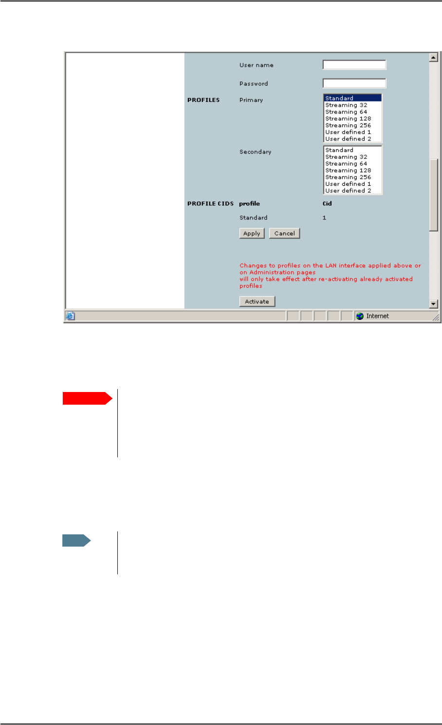
Chapter 5: Using the web interface
98-122988-DraftB6 Setting up the interfaces 109
10. Select the Primary Profile.
Select a Profile from the Primary scroll list. This Profile is used by the LAN interface as a first
choice, when possible.
There are 5 predefined Profiles: Standard, Streaming 32 kbps, Streaming 64 kbps, Streaming
128 kbps and Streaming 256 kbps. Additionally, you can define your own custom Profiles.
For further information on Profiles and Traffic Flow Templates, see Using Profiles on page 127
and Using a Traffic Flow Template on page 130.
11. Select the Secondary Profile.
To select more than one secondary Profile, press and hold Ctrl or Shift while selecting.
The Context Identifiers (CIDs) for the selected primary and secondary Profiles are listed under
Profile CIDs.
12. Click Apply.
Note that changes to your Profiles are not activated until you click Activate.
13. Click Activate if you want to activate the changes to your Profiles.
Important If you have selected a Streaming connection as your Primary Profile, the LAN
interface will be running a Streaming connection until you select another
Profile or disconnect the interface. However, if you select one or more
Secondary Profiles, you can set up your Traffic Flow Template so that it will only
use the Streaming Profile for certain types of traffic.
Note If you have selected both a Primary and one or more Secondary Profiles you
must define a Traffic Flow Template before you can establish a valid
connection.
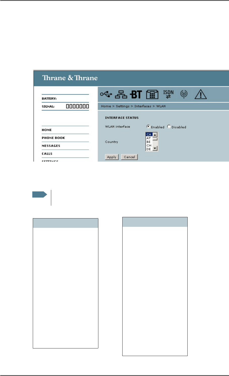
Chapter 5: Using the web interface
98-122988-DraftB6 Setting up the interfaces 110
Configuring the WLAN interface
Note that the settings from the LAN window, except Enabled/Disabled, also apply for the WLAN
interface. See Configuring the LAN interface on page 107.
To configure the WLAN interface, do as follows:
1. Select SETTINGS > Interfaces > WLAN.
2. Select whether the WLAN interface should be Enabled or Disabled.
3. Select the Country code for your present location.
The list below explains the country codes.
Note The country code must be entered before you can continue with the WLAN
configuration and/or use the WLAN interface.
Code Country
US USA
TW Taiwan
CA Canada
AT Austria
BE Belgium
CH Switzerland
DE Germany
DK Denmark
ES Spain
FI Finland
FR France
GB United Kingdom
GR Greece
HU Hungary
IE Ireland
IS Iceland
LI Liechtenstein
IT Italy
LU Luxembourg
NL Netherlands
NO Norway
PL Poland
PT Portugal
SE Sweden
JP Japan
IL Israel
SG Singapore
KR Korea
CN China
Code Country
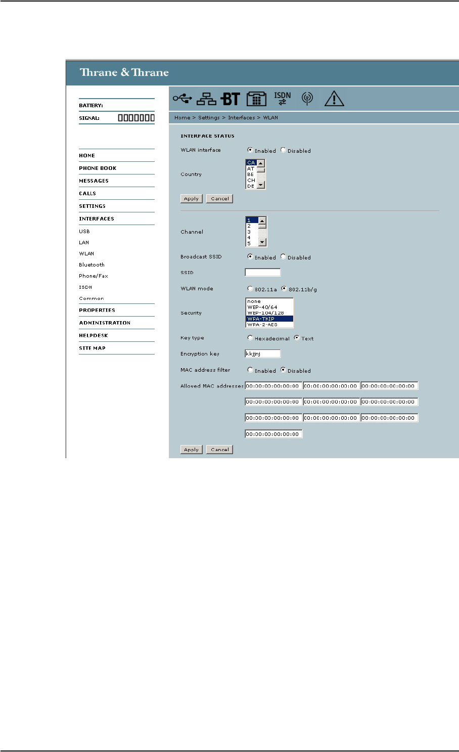
Chapter 5: Using the web interface
98-122988-DraftB6 Setting up the interfaces 111
4. Click Apply
5. Select the Channel number used for communication on the WLAN interface.
6. Next to Broadcast SSID, select Enabled or Disabled.
If you select Enabled your WLAN access point is shown to other users.
If you select Disabled your WLAN access point is hidden.
7. Type in the SSID.
The SSID is a max. 32 character text identifying the wireless local area network. All wireless
devices on a WLAN must use the same SSID in order to communicate with each other. The
default SSID is EXPLORER 700.
8. Select the WLAN mode.
The WLAN mode can be 802.11a (5 GHz) or 802.11b/g (2.4 GHz).
Note that the settings available depend on the entered country code. Also, in some countries
the 5 GHz mode is restricted to indoor use.

Chapter 5: Using the web interface
98-122988-DraftB6 Setting up the interfaces 112
9. Select the Security standard. You may select one of the following encryption standards:
•None
•WEP—40/64
•WEP—104/128
•WPA—TKIP
•WPA—2—AES
10. Select Hexadecimal or Text next to Key type.
The encryption key must normally be a hexadecimal code. However, if you are using WPA or
WPA-2 encryption you can choose to use a text string, which may be easier to memorize.
11. Type in the Encryption key for the selected Security standard (not applicable if security mode
= None).
12. Select Enabled or Disabled next to MAC address filters.
If you select Enabled, you can set up a list of MAC addresses that are allowed access to your
WLAN. Any device whose MAC address is not on the list will be denied access.
If you select Disabled, there will be no restrictions on MAC addresses.
13. If you have enabled MAC address filters, type in the Allowed MAC addresses.
The list may contain up to 10 MAC addresses.
14. Click Apply.
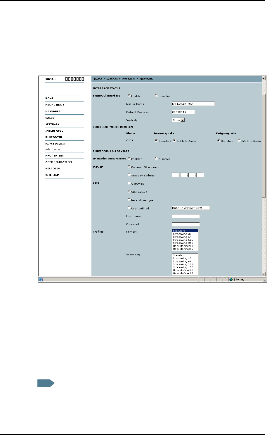
Chapter 5: Using the web interface
98-122988-DraftB6 Setting up the interfaces 113
Configuring the Bluetooth interface
For an explanation of each of the data settings, see Description of data settings on page 103.
To configure the Bluetooth interface, do as follows:
1. Select SETTINGS > Interfaces > Bluetooth.
2. Under BLUETOOTH VOICE DEVICES, set the call type for incoming and outgoing calls. All
paired voice devices are listed with their local phone numbers.
Call types are described in more detail in Selecting the call type on page 51.
•For Incoming calls, you can check Standard or 3.1 kHz Audio or both.
If you check both, the voice device will react (ring) on incoming calls.
If you select e.g. Standard, the voice device will only react on calls made to the Standard
phone number.
•For Outgoing calls, you can select either Standard or 3.1 kHz Audio. The selected type will
be used by default, if possible, for any outgoing call. Note, however, that fax machines and
modems must use 3.1 kHz Audio.
Note You can override the default setting for outgoing calls by dialing 1* (force a Standard
call) or 2* (force a 3.1 kHz Audio call) before the number. For further information,
see Overriding the default outgoing call type on page 51.

Chapter 5: Using the web interface
98-122988-DraftB6 Setting up the interfaces 114
3. For data devices, the settings are listed under the Bluetooth profile that is used (Dial-up
network or LAN). The next steps describe the settings available under a Bluetooth profile.
4. Under IP Header compression, select Enabled or Disabled.
For information on Header Compression, see Header compression on page 103.
5. Under TCP/IP, select whether your computer uses a Dynamic IP address or a Static IP address.
If you are using a static address, type in the address.
This is the IP address used externally on the satellite network.
To check this setting on your computer, see the TCP/IP properties of the Bluetooth connection.
6. Under APN, select the source of the APN (Access Point Name).
There are four options for setting the APN. Unless you have special requirements, it is
recommended to use the SIM default, or to set the common APN to SIM default, and then
select Common here. You have the following options:
•Common. The APN is taken from the Common APN defined under
SETTINGS > Interfaces > Common. Refer to Setting a common APN on page 120.
•SIM default. The APN is taken from the SIM card.
•Network assigned. The APN is assigned from the network.
•User defined. Type in the APN. APNs are provided from the Airtime Provider.
7. If your APN uses a password, type in the user name and password provided from the Airtime
Provider.
8. Select the Primary Profile.
Select a Profile from the scroll list. This Profile is used by the Bluetooth interface as a first
choice, when possible.
There are 5 predefined Profiles: Standard, Streaming 32 kbps, Streaming 64 kbps, Streaming
128 kbps and Streaming 256 kbps. Additionally, you can define your own custom Profiles.
For further information on Profiles and Traffic Flow Templates, see Using Profiles on page 127
and Using a Traffic Flow Template on page 130.
9. Select the Secondary Profile.
10. Click Apply.
Important If you have selected a Streaming connection as your Primary Profile, the
Bluetooth interface will be running a Streaming connection until you select
another Profile or turn off the interface. However, you can set up your Traffic
Flow Template so that it will only use this Profile for certain types of traffic.
Note If you have selected both a Primary and one or more Secondary Profiles you must
define a Traffic Flow Template before you can establish a valid connection.
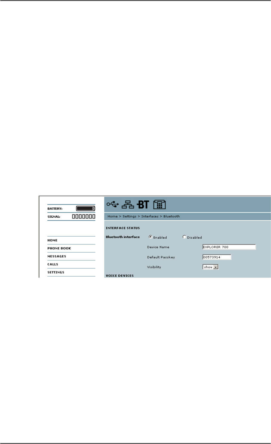
Chapter 5: Using the web interface
98-122988-DraftB6 Setting up the interfaces 115
Pairing Bluetooth devices from the web interface
What is pairing?
Bluetooth Pairing happens when two Bluetooth enabled devices agree to communicate with one
another. When this happens, the two devices exchange passkeys and join a pair. The pairing
process only takes place the first time the two devices are connected. Once the two devices have
established a pair, they automatically accept communication when one device recognizes the
other device.
Preparing the EXPLORER™ 700 for Bluetooth pairing
To prepare the Bluetooth interface on the EXPLORER™ 700, do as follows:
1. Connect a computer to the EXPLORER™ 700, e.g. using the LAN interface.
2. Access the web interface from your connected computer.
Refer to The web interface on page 80.
3. In the web interface, select SETTINGS > Interfaces > Bluetooth and make sure that Bluetooth
is Enabled.
4. Use the predefined Device name or type in a new name for your EXPLORER™ 700.
The Device name is shown to other Bluetooth devices, if the EXPLORER™ 700 is configured to
be shown (refer to step 6. below).
5. Use the predefined Default passkey or type in a new one.
This passkey is used by default when pairing devices with the EXPLORER™ 700.
6. Next to Visibility, select Show or Hide.
• If you select Show, the device name of the EXPLORER™ 700 is shown to other Bluetooth
devices that are searching for devices.
• If you select Hide, other Bluetooth devices will not see the EXPLORER™ 700.
7. Click Apply at the bottom of the window.

Chapter 5: Using the web interface
98-122988-DraftB6 Setting up the interfaces 116
Pairing from your Bluetooth device
For information on how to pair devices from your Bluetooth device, see Pairing devices in which
you can enter a passkey on page 50.
Pairing devices with a fixed passkey
Some Bluetooth devices, such as headsets, do not provide the possibility to enter a passkey for
connecting to another device. These devices have a fixed passkey which must be entered on the
other device. This section describes how to pair such devices with the EXPLORER™ 700.
Do as follows to pair the devices:
1. Connect a computer to the EXPLORER™ 700, e.g. using the LAN interface.
2. Start up the EXPLORER™ 700.
Refer to Getting started on page 12.
3. Turn on Bluetooth on your Bluetooth device and place it close to the EXPLORER™ 700.
4. Access the web interface from your connected computer.
For further information, see The web interface on page 80.
5. Select SETTINGS > Interfaces > Bluetooth and make sure that Bluetooth is Enabled.
6. From the left menu of the Bluetooth window, select Add device.
Note that you can pair maximum 7 devices. If you have already paired 7 devices, you have to
unpair a device before you can pair a new one. For information on how to unpair devices, see
Unpairing devices on page 117.
7. Click Search.
The EXPLORER™ 700 now searches for Bluetooth devices.
8. Click Update.
9. When the device you want to pair appears in the list, click Pair next to the device.
10. Enter the passkey of your Bluetooth device.
The default passkey for a Bluetooth headset is often 0000. Otherwise, refer to the manual for
your Bluetooth device.
11. When you are prompted from the Bluetooth device, usually by a tone, press the button on the
device to accept pairing.
The new device should now be paired with the EXPLORER™ 700 and added to the list of Paired
devices. This list is accessed from the left menu of the Bluetooth window in the web interface.
Note The method for pairing devices may vary depending on your Bluetooth device. Consult
your Bluetooth device documentation for information.
Note The search procedure can take up to 2-3 minutes. The list is not updated
dynamically. Click Update to see new found devices.

Chapter 5: Using the web interface
98-122988-DraftB6 Setting up the interfaces 117
As long as the Bluetooth device is in the list of Paired devices, you can always reconnect the
device to the EXPLORER™ 700 without further setup.
Viewing paired devices
To see a list of devices that are paired with the EXPLORER™ 700, do as follows:
1. Access the web interface.
Refer to The web interface on page 80.
2. Select SETTINGS > Interfaces > Bluetooth > Paired devices.
The list shows all devices that are paired with the EXPLORER™ 700. You can see the name, Class of
Device, status (whether or not a device is currently connected) and local phone number.
You can also see paired devices in the display. Select PROPERTIES > BLUETOOTH
DEVICES in the display menu system to see a list of all paired devices.
Unpairing devices
To remove a device from the list of Paired devices, do as follows:
1. Access the web interface and select
SETTINGS > Interfaces > Bluetooth > Paired devices.
2. In the Paired devices list, click Unpair next to the device you want to remove.
When the device is removed from the list, you have to pair it with the EXPLORER™ 700 again to
make a connection.
Note If you need to unpair an EXPLORER™ Bluetooth Handset, make sure the handset is
connected to the EXPLORER™ 700 while you unpair it.
If you select Unpair while the handset is not connected, it will automatically be
paired again when it approaches the EXPLORER™ 700.

Chapter 5: Using the web interface
98-122988-DraftB6 Setting up the interfaces 118
Configuring the Phone/Fax settings
Do as follows:
1. Select SETTINGS > Interfaces > Phone/Fax from the left navigation pane.
2. Select Enabled or Disabled to enable/disable the Phone/Fax interface.
3. Set the call type for incoming and outgoing calls.
Call types are described in more detail in Selecting the call type on page 51.
•For Incoming calls, you can check Standard or 3.1 kHz Audio or both.
If you check both, any device connected to the Phone/Fax interface will react (ring) on
incoming calls.
If you select e.g. Standard, the Phone/Fax interface will only react on calls made to the
Standard phone number.
•For Outgoing calls, you can select either Standard or 3.1 kHz Audio. The selected type will
be used by default, if possible, for any outgoing call. Note, however, that fax machines and
modems must use 3.1 kHz Audio.
4. Click Apply.
Note You can override the default setting for outgoing calls by dialing 1* (force the call to
Standard) or 2* (force the call to 3.1 kHz Audio) before the number. For further
information, see Overriding the default outgoing call type on page 51.

Chapter 5: Using the web interface
98-122988-DraftB6 Setting up the interfaces 119
Configuring the ISDN interface
To configure the ISDN interface, do as follows:
1. Select SETTINGS > Interfaces > ISDN.
2. Select whether the ISDN interface should be Enabled or Disabled.
3. Select whether the 38 V power output of the ISDN interface should be Enabled or Disabled.
If the connected ISDN device is self-powered, you should disable 38 V power.
4. For each ISDN port, set the call type(s) for incoming calls.
You can select Standard, 3.1 kHz Audio, UDI and/or RDI.
5. For each ISDN port, set the MSN numbers that are to be assigned to each call type.
Note that this setting only applies to the call type selected above the MSN number, and only if
the connected device supports the call type used.
You have the following options with the MSN numbers:
•<None>. No MSN numbers are used. An incoming call is accepted in all devices connected
to this port.
•1*, 2*, 3* or 4*: If, for example, you select 1* at Standard call type for port 1, an incoming
Standard call is accepted by all devices on port 1 that are programmed with the number 1*.
•0401….0408: These are local numbers for separate devices connected to port 1.
0411….0418: These are local numbers for separate devices connected to port 2.
An incoming call is accepted by devices that are programmed with the selected number and
connected to the correct port.
You can combine the MSN settings.
Example: You have two devices connected to the same port. One is programmed with the
numbers 1* and 0401, the other is programmed with 1* and 0402.
In the web interface, you select the MSN number 1* under Standard.
If an incoming Standard call arrives, both devices will accept the call.
If you make a local call to one of the local numbers 0401 or 0402, only the called
device will accept the call.
Note Connected devices will only receive incoming calls with the call types that are
selected here.
For example, if only Standard is selected for port 1, and a G4 fax call (using call type
UDI) arrives, a fax connected to port 1 will not receive the incoming call.
Important If you set an MSN number to anything other than <None>, all connected
devices must be programmed with MSN numbers.

Chapter 5: Using the web interface
98-122988-DraftB6 Setting up the interfaces 120
6. For each ISDN port, set the call type for outgoing calls.
• If you select Automatic, the call type will be determined by the calling device.
• If you select Standard, all outgoing calls, except UDI/RDI, will use the call type Standard. If
you make a 3.1 kHz Audio call it will be converted to a Standard call.
UDI or RDI sessions will be not be influenced by this setting.
• If you select 3.1 kHz Audio, all outgoing calls, except UDI/RDI, will use the call type 3.1 kHz
Audio. If you make a Standard call it will be converted to a 3.1 kHz Audio call. UDI or RDI
sessions will be not be influenced by this setting.
7. Click Apply.
Setting a common APN
Setting the common APN
The common APN setting is defined here and can be selected for each interface. If you are using
the same APN for many interfaces, it is easier to define it once, and then simply select it for the
relevant interfaces. Also, if you change the common APN at a later stage, it is automatically
updated for all interfaces where the Common setting is selected.
To set a common APN, do as follows:
1. Select SETTINGS > Interfaces > Common.
2. Select the APN. You have the following options:
•SIM default. The APN is taken from the SIM card. This is the recommended option, unless
you have special requirements.
•Network assigned. The APN is assigned from the network.
•User defined. Type in the APN. APNs are provided from the Airtime Provider.
3. If your APN uses a password, type in the user name and password provided from the Airtime
Provider.
4. Click Apply.
How to use the common APN
When you configure your individual interface, select Common to use the setting from this window.
Where Common is selected in the individual interface settings, the setting will automatically be
updated when the Common APN is changed.
Note You can override the call type setting for outgoing calls by dialing one of the
following prefixes before the number:
• 1* (force the call to Standard)
• 2* (force the call to 3.1 kHz Audio)
Refer to Overriding the default outgoing call type on page 51.

Chapter 5: Using the web interface
98-122988-DraftB6 Properties, software upload and alarm list 121
Properties, software upload and alarm list
Viewing the properties of the EXPLORER™ 700
To view the properties of the EXPLORER™ 700, select PROPERTIES from the left menu.
The PROPERTIES window shows:
•Local IP address. The local IP address of the EXPLORER™ 700.
•IMEI number. The IMEI number (International Mobile Equipment Identity) of the
EXPLORER™ 700. This is a unique number that identifies your EXPLORER™ 700.
•SMS service center. A number used to identify the SMS service center used by your
EXPLORER™ 700 to send and receive SMS messages.
•Mobile subscriber numbers (if available on SIM card). The numbers to use for Standard Voice,
3.1 kHz Audio and data connection when calling the EXPLORER™ 700.
•Software version. The version of the software embedded in the EXPLORER™ 700.
•Unit serial number. The serial number of the total unit.
•PCB numbers. The numbers of the PCBs in the EXPLORER™ 700.
•MAC address for the LAN and Bluetooth interfaces in the EXPLORER™ 700.
•WLAN MAC address for the WLAN interface in the EXPLORER™ 700.
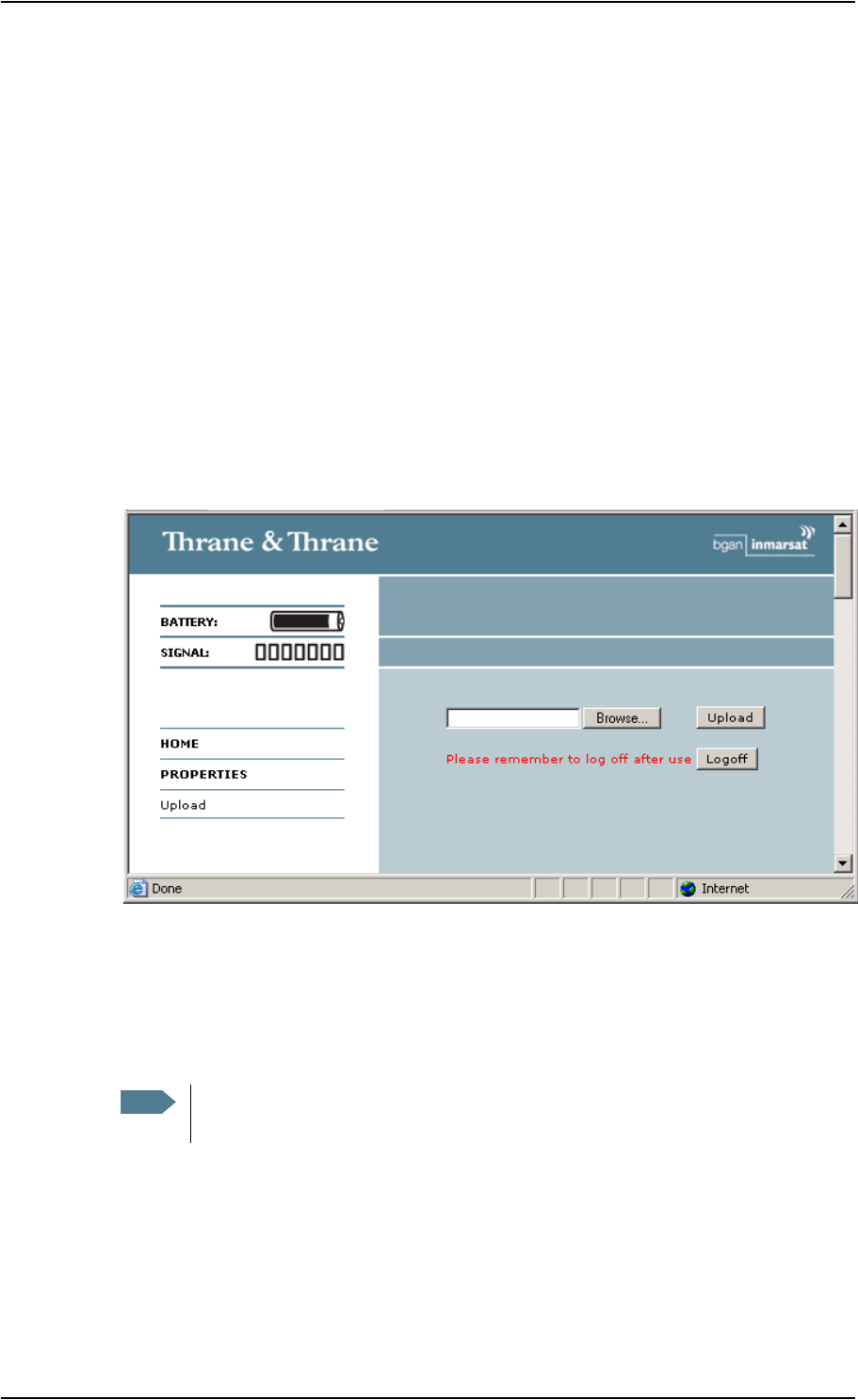
Chapter 5: Using the web interface
98-122988-DraftB6 Properties, software upload and alarm list 122
Uploading software
You can upload software to the EXPLORER™ 700 without entering the PIN. However, if the PIN is
not entered, you must enter the Administration user name and password.
To upload software to the EXPLORER™ 700, do as follows:
1. Acquire the new software version from Thrane & Thrane and save it on your computer.
2. In the web interface, select PROPERTIES from the left navigation pane.
The Software version field shows the current software version.
3. Click Upload from the left navigation pane.
If you have not entered the PIN at start-up, you are prompted for an Administration user
name and password.
4. If required, type in the Administration user name and password and click Logon.
The default user name is admin and the default password is 1234.
5. Click Browse…
6. Browse to the new software version and accept it.
7. Click the Upload button.
Note that the upload procedure takes a couple of minutes.
Note When upload is done, your EXPLORER™ 700 automatically restarts with the new
software.
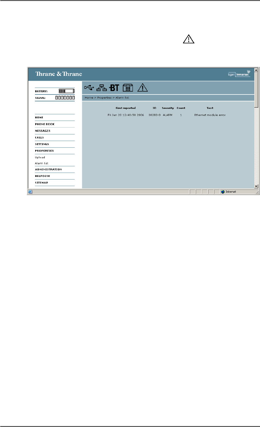
Chapter 5: Using the web interface
98-122988-DraftB6 Properties, software upload and alarm list 123
Viewing the Alarm List
When an alarm is issued, the web interface shows an alarm icon in the icon bar.
To view the Alarm list, click the alarm icon from the icon bar at the top of the web interface or
select Properties > Alarm list from the left navigation pane.
The Alarm list window shows a detailed list of active alarms including the time of the first
occurrence, ID and severity of the alarm message, number of occurrences and a short text
describing the error. For more information on the alarm messages, refer to Alarm messages on
page 146.
If you need to report the alarms for service purposes, make sure you include the complete ID
number. This number is used by service personnel to uniquely identify an alarm.
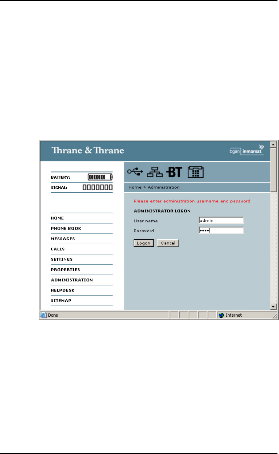
Chapter 5: Using the web interface
98-122988-DraftB6 Administration 124
Administration
Accessing the administration settings
Logging on
The Administration settings require an Administration user name and password.
1. Select ADMINISTRATION from the left navigation pane.
2. Enter the Administration user name and password.
The default user name is admin and the default password is 1234.
The next section explains how to change the user name and password.
3. Click Logon.
The Administration window is now updated to let you change the user name and password,
Save/load a configuration or log off Administration.
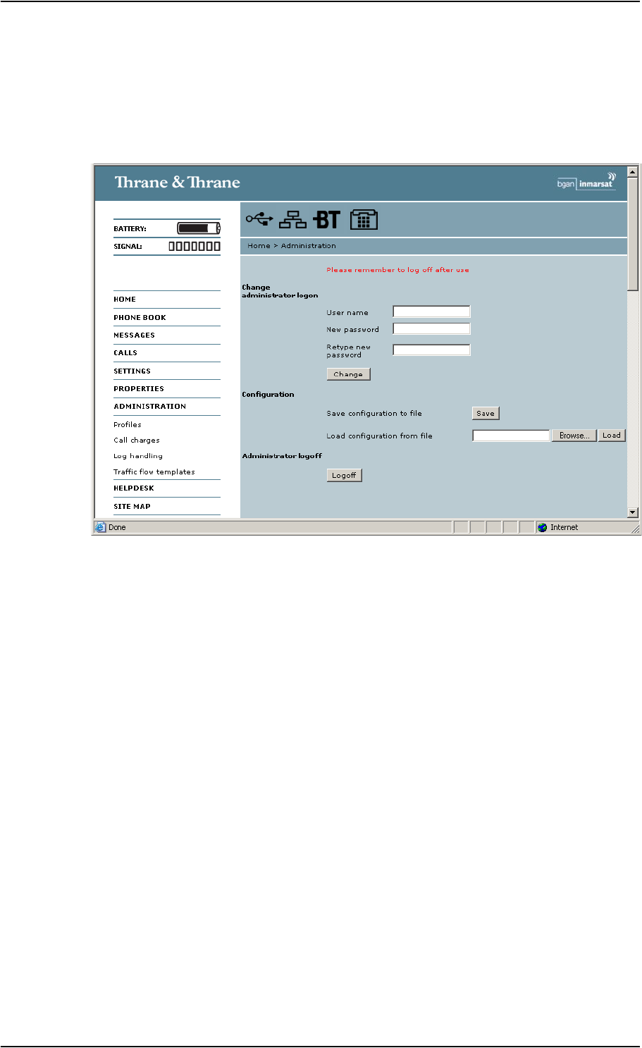
Chapter 5: Using the web interface
98-122988-DraftB6 Administration 125
Changing the administration password
Do as follows:
1. After entering the Administration user name and password in the ADMINISTRATION window,
locate the section Change administrator logon.
2. Type in the existing user name.
3. Type in the new password twice.
4. Click Change.
At the next logon the new password is required.
Saving a configuration to a file
If you need to reuse a configuration in another EXPLORER™ 700, you can save your current
configuration to a file, which can then be loaded into the other EXPLORER™ 700.
Do as follows:
1. In the ADMINISTRATION window, under Configuration, click Save.
2. Accept the default destination file name or type in the destination file name and location.
3. Click OK.
The configuration is now saved to a file. This file is used to load the configuration into another
EXPLORER™ 700. See the next section.

Chapter 5: Using the web interface
98-122988-DraftB6 Administration 126
Loading a configuration from a file
1. In the ADMINISTRATION window, under Configuration, click Load.
2. Click Browse… to browse to the file you want to import. Then click Open.
3. Click Load.
The new configuration is now loaded into your EXPLORER™ 700.
Logging off administration
If you have not entered anything for 30 minutes under ADMINISTRATION, you are logged off
automatically.
To log off manually, click Logoff under Administrator logoff in the ADMINISTRATION window.
Call charges
If you know the tariff for your subscribed services, you can enter these tariffs in the web interface
and automatically calculate the charges for your calls and data sessions.
Do as follows:
1. From the left navigation pane, select
ADMINISTRATION > Call Charges
2. Select the currency from the Currency drop-down list.
3. Enter the tariff for each of the services.
4. Click Apply.
The entered tariffs are used for estimating the charges for calls and data sessions. The
estimated charge is listed for each call or data session in the call log. For further information,
see Viewing the lists of calls on page 92.
Log handling
1. From the left navigation pane in the ADMINISTRATION window, select Log Handling.
2. To clear the Call log, click OK next to Clear call log?.
3. To clear the total counters, click OK next to Clear total counter?.
This will reset the Time connected counters on the Calls page.
Note Thrane & Thrane does not take responsibility for the correctness of the estimated
charges. This calculation is only a rough estimate of the charge, based on the tariff
entered by the user. Also, the Airtime Provider may have different methods of calculating
the charge.

Chapter 5: Using the web interface
98-122988-DraftB6 Administration 127
Using Profiles
What is a Profile?
A Profile is a collection of Quality of Service (QoS) settings and other settings defining the mode in
which data is transmitted on an interface. For example, a Profile is used to define whether the
connection is a Streaming connection or a Standard connection.
You can select between a number of predefined Profiles or define your own Profiles for your data
transmission.
If no Traffic Flow Template (TFT) is defined, the Primary Profile for an interface is used for all traffic
on that interface. See What is a Traffic Flow Template? in the next section.
For further information on Profiles, refer to the 3GPP standard TS 23.107.
Selecting the Profiles for an interface
When you set up your interface, you select the Profiles to use for that interface. You select a
Primary Profile and optionally one or more Secondary Profiles.
For further information on how to select the Profiles, see the “Configuring…” sections for the
individual interfaces in this chapter.
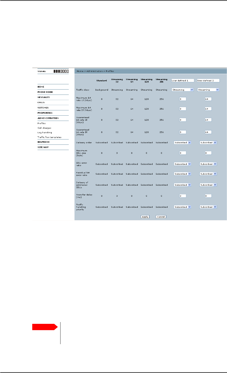
Chapter 5: Using the web interface
98-122988-DraftB6 Administration 128
Defining new Profiles
When you define your Profiles you can select Subscribed for many of the settings. If you select
Subscribed, the value given in your Airtime subscription will automatically be used.
To define a new Profile, do as follows:
1. From the left navigation pane, select ADMINISTRATION > Profiles.
2. In one of the User defined columns, fill in the top field with the name of your Profile.
3. In the Traffic class row of your new Profile, select a class from the drop-down list.
You may select one of the following:
•Conversational is real-time two-way conversation. It is primarily used for voice over IP and
video conferencing.
•Streaming is real-time one-way communication. It is primarily used for video and audio.
•Interactive is two-way communication (not real-time). It is used for communication that is
not very delay-sensitive, such as web browsing, data base retrieval and server access.
Examples of machines interaction with remote equipment are: polling for measurement
records and automatic data base enquiries (tele-machines).
•Background is used for data which is not delay-sensitive, such as E-mails, SMS, download
of databases and reception of measurement records.
Important For best performance, choose the right traffic class for your application. In
general, Standard data (Background) is best suited for TCP/IP applications, and
Streaming data is best suited for UDP traffic, e.g. live video or audio.

Chapter 5: Using the web interface
98-122988-DraftB6 Administration 129
4. Type in the bit rates in kbps in the following rows:
•Maximum bit rate ul (kbps) is the maximum upload bit rate allowed for this Profile.
•Maximum bit rate dl (kbps) is the maximum download bit rate allowed for this Profile.
•Guaranteed bit rate ul (kbps) is the guaranteed upload bit rate needed for this Profile.
•Guaranteed bit rate dl (kbps) is the guaranteed download bit rate needed for this Profile.
5. In the Delivery order row, select from the scroll list whether or not data should be delivered in
the same order it was sent. Yes means the data packets are delivered in the same order they
were sent.
6. In the Maximum SDU size (byte) row, type in the maximum allowed packet size in Bytes
(rounded off to nearest 10). The maximum packet size possible is 1520.
7. In the Delivery of erroneous SDUs row, select one of the following from the list:
•Yes means packets are allowed to contain errors. This setting is suitable for delay-sensitive
transmission, because the need for retransmission is limited. The SDU Error settings in step
8. and step 9. will apply.
•No means packets are not allowed to contain errors, and the SDU Error setting in step 8.
will not be applied. This setting is suitable where error-free transmission is important and
delays are accepted.
•No detect means that errors will not be detected, and the SDU Error setting in step 8. will
not be applied.
8. If you selected Yes in step 7., select from the SDU error ratio drop-down list the fraction of a
packet allowed to be lost or erroneous.
9. Select from the Residual bit error ratio drop-down list the undetected bit error ratio of a
packet. If no error detection is requested, Residual bit error ratio indicates the bit error ratio
in the delivered packets.
10. In the Transfer delay (ms) row, type in the delay in ms. This is the delay from data is received
in the EXPLORER™ 700 until it arrives at the receiving end.
11. In the Traffic handling priority row, select from the drop-down list which priority this
connection should have.
12. Click Apply.
The new Profile is now added, and can be selected from the lists of primary and secondary
Profiles when you set up your interfaces.
Note When you click Apply, the bit rate values you typed in may be rounded off because
only certain values are allowed.

Chapter 5: Using the web interface
98-122988-DraftB6 Administration 130
Using a Traffic Flow Template
What is a Traffic Flow Template?
A Traffic Flow Template (TFT) is a packet filter list allowing the Core network and the
EXPLORER™ 700 to classify packets received from the external network into the proper PDP
(Packet Data Protocol) context.
A TFT consists of from one and up to eight packet filters, each identified by a unique packet filter
identifier. A packet filter also has an evaluation precedence index that is unique within all TFTs
associated with the PDP contexts that share the same PDP address.
Information of source, destination, type of service etc. is combined in each packet filter in the TFT.
Purpose of the Traffic Flow Template
The purpose of the TFT is to assign different priorities to different types of traffic, in order to
optimize performance.
Example: When you are browsing the Internet, a Standard data connection will normally be
sufficient. However, if you need to have a video conference, you may need to use a Streaming
connection, in order to obtain a direct connection without interruptions. Your Traffic Flow
Template can define these priorities, so that your connection automatically switches to Streaming
e.g. when you have a video conference.
Defining the Traffic Flow Template
To define a new template, do as follows:
1. From the left navigation pane, select
ADMINISTRATION > Traffic Flow Templates.
2. Select which filters should apply to which Profiles.
The filters are defined in the Traffic flow filters list. Refer to the next section
3. Click Apply.
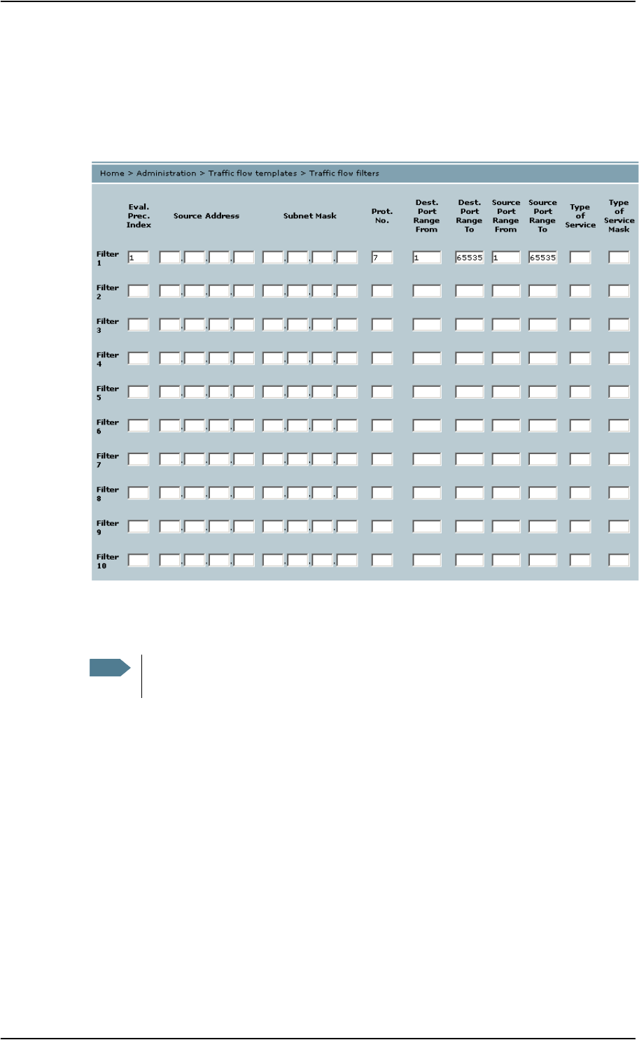
Chapter 5: Using the web interface
98-122988-DraftB6 Administration 131
Defining filters for the Traffic Flow Template
To define the filters used in the Traffic flow template, do as follows:
1. From the left navigation pane, select
ADMINISTRATION > Traffic Flow Templates > Traffic flow filters.
Then fill in the details for each traffic flow filter as described below.
2. Type in an Evaluation Precedence Index in the Eval.Prec. Index column.
3. Fill in one or more of the following fields to define the filter.
The allowed ranges appear in hover text when you pass the mouse over the fields.
•Source address + Subnet mask.
•Protocol number.
•Destination port range (From and To). Note that Source and Destination are relative the
core network. This means that Destination is your EXPLORER™ 700 terminal.
•Source port range (From and To).
•Type of Service + Type of Service mask.
For further information on the principles and parameters of the Traffic Flow Template, refer to
the 3GPP standards TS27.007 V4.2.0 and TS 23.060 V4.7.0.
4. Click Apply at the bottom of the window.
The new settings are included if you select the filter in the Traffic flow template window.
Note This field is mandatory. Each filter must have a different Evaluation Precedence
Index.

Chapter 5: Using the web interface
98-122988-DraftB6 Help desk and diagnostic report 132
Help desk and diagnostic report
Accessing the Help desk
If you need help with airtime-related issues you may call the Help desk. By default, the Help desk
is the phone number for your Airtime Provider, if it is available on the SIM card.
Select HELP DESK from the left navigation pane.
If the Help desk number is available on the SIM card, the number is displayed as a link. To change
the number, click the link, change the number and click Apply.
If you need help with EXPLORER™ 700 issues you should call your local distributor.
Generating a diagnostic report
If you want to generate a diagnostic report, do as follows:
1. Click Generate report from the HELP DESK window.
In some browsers the file may open directly in your browser. If it does, choose File > Save As
to save the file.
2. Choose a location for the file and save it.
The diagnostic report contains relevant information for troubleshooting. Please enclose this file
when you are reporting an error.
What’s next?
This chapter has explained how to use the web interface for setup and use of the EXPLORER™ 700.
You should now be able to set up the EXPLORER™ 700, pair Bluetooth devices, check status, read
and send SMS messages, use the phone book and much more.
The following chapter, Maintenance and troubleshooting, provides guidelines for troubleshooting
and for general maintenance.

98-122988-DraftB6 133
Chapter 6
Maintenance and troubleshooting 6
In this chapter
This chapter gives guidelines for troubleshooting and for general maintenance. It also provides an
overview of the different means of status signaling,
Getting support
Overview
If this manual does not provide the information required to solve your problem, you may want to
contact your Airtime Provider or your local distributor.
Airtime support
If you need assistance from your Airtime Provider, please call the help desk.
To see the help desk number, enter the display menu system or the web interface of your
EXPLORER™ 700 and select HELP DESK. This help desk number is either taken from the SIM card
or entered manually. If no number is available under HELP DESK, check your Airtime subscription
for a contact number.
EXPLORER™ 700 support
If you need assistance with problems caused by the EXPLORER™ 700, please call a distributor in
your area.
Click this link to see a list of Thrane & Thrane distributors.
Note The list of distributors is located on the EXPLORER™ 700 CD-ROM delivered with your
EXPLORER™ 700, so it may not always be up to date.
An updated list is available on Thrane & Thrane’s web site: www.thrane.com.
Click Land Mobile and select Distributors from the top menu bar.

Chapter 6: Maintenance and troubleshooting
98-122988-DraftB6 134
Uploading software
Viewing software version status
To view the version of the embedded software in the EXPLORER™ 700, select PROPERTIES in the
web interface or in the display menus and see Software information.
Uploading software using the web interface
You can upload software from the PROPERTIES > Upload window in the web interface.
If you have an Administrator user name and password you do not need to insert a SIM card nor to
enter the PIN to be able to upload software.
For further information, see Uploading software on page 122.
Maintenance
Normal use of the battery
It is recommended not to partially charge/discharge the battery several times in a row. Partial
charging/discharging affects the accuracy of the capacity measurement.
Never leave the battery fully discharged for a longer period of time. If the battery is not to be used
for a shorter period of time (1 month), charge the battery to minimum 20 to 30% and remove it
from the EXPLORER™ 700. If the Battery is stored for more than a month, see Storage at the end of
this section.
Recharging the battery
To recharge the battery, insert it into the EXPLORER™ 700 and connect the EXPLORER™ 700 to
power.
The indicator left to the display is constantly green as long as the battery is charging. When the
battery is fully recharged, the green indicator is turned off. If the EXPLORER™ 700 is switched on,
the green indicator will be flashing shortly every 2 seconds.
If a charging error occurs, the green indicator on the EXPLORER™ 700 flashes rapidly. See the
Troubleshooting Guide on page 137.
Note Normally the charge time is approximately 2.5 hours. However, if the EXPLORER™ 700 is
operating while being charged, the charge time is increased.

Chapter 6: Maintenance and troubleshooting
98-122988-DraftB6 135
Accurate display of the battery capacity
To ensure accurate display of the battery capacity, it is recommended to run a “learning cycle” for
every 100 recharge/discharge and at first time use. The learning cycle must be performed at 20°C-
30°C.
A learning cycle is performed as follows:
1. Fully charge the battery.
2. Remove external power and fully discharge the battery:
Use the EXPLORER™ 700 and/or leave it on until it turns off automatically.
This way the EXPLORER™ 700 “learns” the complete capacity of the battery.
Note that it may take up to 36 hours to discharge the battery if it is not in use.
3. Recharge the battery.
Storage
Do not leave the battery inserted in the EXPLORER™ 700 during storage.
If the battery is not to be used for a longer period of time, do as follows:
1. Fully charge the battery.
2. Remove external power. Then use the EXPLORER™ 700 or leave it on until the display shows a
battery capacity of approximately 50%.
3. Switch off the EXPLORER™ 700.
4. Remove the battery and store it.
In this condition the battery can be stored for approximately 1 year at 20°C to 30°C. After 1 year you
must recharge the battery. For further information on storage temperature, see Battery on
page 154.
Disposal of the EXPLORER™ 700
Old electrical and electronic equipment marked with this symbol can
contain substances hazardous to human beings and the environment.
Never dispose these items together with unsorted municipal waste
(household waste).
In order to protect the environment and ensure the correct recycling of old equipment as well as
the re-utilization of individual components, use either public collection or private collection by the
local distributor of old electrical and electronic equipment marked with this symbol.
Contact the local distributor for information about what type of return system to use.
Important Switch off the EXPLORER™ 700 before removing the battery!
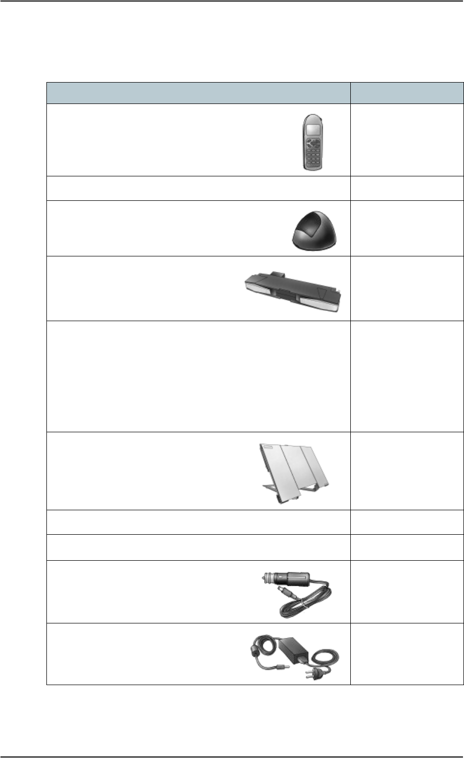
Chapter 6: Maintenance and troubleshooting
98-122988-DraftB6 136
Options and accessories
The following options and accessories are available from Thrane & Thrane:
Item Number
EXPLORER™ Bluetooth Handset + charger cable
TT-3625A
EXPLORER™ 2-wire phone + cable TT-3625B
Desktop charger cradle for EXPLORER™ Bluetooth
Handset + power supply
TT-3625A, Opt. 003
EXPLORER™ 700 Battery
TT-3686P
Antenna cables, current rating: 2.5 A:
41.5 cm
10 m
30 m
60 m
100 m
TT-3720A, Opt.937
TT-3720A, Opt.942
TT-3720A, Opt.945
TT-3720A, Opt.948
TT-3720A, Opt.955
EXPLORER™ 700 antenna TT-3703A
Pole mount kit for EXPLORER™ 700 antenna TT-3650A, Opt. 920
EXPLORER™ 700 Softbag TT-3720A, Opt. 202
EXPLORER™ 700 Car charger cable
TT-3720A, Opt. 009
AC/DC adapter TT-3682P
FSP 065-AAC

Chapter 6: Maintenance and troubleshooting
98-122988-DraftB6 137
Troubleshooting guide
The below table provides information on some of the problems that might occur, including
possible causes and remedies to solve the problems.
Problem Possible Cause Remedy
The EXPLORER™ 700
cannot be switched
on, or does not stay
on when powered by
the battery.
The battery needs
recharging.
Recharge the battery. Check the battery
indicator in the display.
The battery is not inserted
properly.
Remove the battery and re-insert it.
Make sure the battery is inserted
properly and that the latches are
locked.
The battery contacts are
dirty or damaged.
Clean the battery contacts if necessary.
If the contacts are damaged, replace the
battery.
There is no light in
the power indicator
nor in the display
when the
EXPLORER™ 700 is
switched on.
The EXPLORER™ 700 may
be in Stealth Mode (all
lights and sounds are off).
Press C+OK on the display keypad. This
will toggle Stealth Mode on/off.
The EXPLORER™ 700
cannot be switched
off.
The Power button was not
pressed long enough.
When you switch off the
EXPLORER™ 700, hold the power button
until the display shows “Switching off”.
In rare cases, it may take up to 10
seconds to switch off the
EXPLORER™ 700.
Charging error —
The green Power
indicator flashes
rapidly while the
battery is being
recharged.
The temperature is below
0°C or above 45°C.
Only charge the battery when the
temperature is within the range 0°C to
45°C.
The charging voltage is
less than 9 V.
Wait until charging begins (the green
Power indicator lights constantly).
If the battery is completely discharged,
and it has been out of use for a long
time, the charging process may take a
long time to start. If charging does not
begin within 2-3 hours, contact your
local distributor, or purchase a new
battery.

Chapter 6: Maintenance and troubleshooting
98-122988-DraftB6 138
The display shows
INSERT SIM.
The SIM card is not
present.
Remove the battery and insert the SIM
card in the SIM slot according to the
instructions in the section Inserting the
SIM card on page 15.
The SIM card is not
inserted properly.
Remove the SIM card and re-insert it
according to the instructions in the
section Inserting the SIM card on
page 15.
The SIM card is inserted in
the wrong SIM slot.
There are two SIM slots, marked
USIM #1 and USIM #2.
Make sure the SIM card is inserted in
the SIM slot marked USIM #1.
The display shows
NO GPS FIX.
The EXPLORER™ 700 is
unable to register on the
network, because the GPS
position is unknown.
Make sure the view to the GPS satellites
is not blocked.
To obtain GPS fix, the EXPLORER™ 700
should be placed flat on an even
surface pointing straight upwards, with
a clear view to as much of the sky as
possible. When the EXPLORER™ 700
has obtained GPS fix, you can point the
antenna towards the BGAN satellite.
To see the GPS status, enter the menu
system and select PROPERTIES >
GPS STATUS.
The display shows
EMERGENCY
ONLY.
The BGAN network is only
available for emergency
calls.
The reason may be one of
the following:
1) You have pressed C on
the EXPLORER™ 700
instead of entering the PIN.
2) Your Airtime
subscription has expired.
3) You are using the wrong
SIM card.
1) If the display reads “ENTER PIN?”
and/or you cannot enter the display
menu system, you may have pressed C
instead of entering the PIN. Unless the
use of PIN is disabled, e.g. from the
BGAN LaunchPad, you must enter the
PIN before you are allowed make calls.
2) Check your subscription with the
Airtime Provider.
3) Check that your SIM card is valid for
communication on the BGAN network.
Problem Possible Cause Remedy

Chapter 6: Maintenance and troubleshooting
98-122988-DraftB6 139
The display shows
NOT
REGISTERED.
The EXPLORER™ 700
cannot register on the
BGAN network.
Check that your SIM card is valid for
communication on the BGAN network.
Check your subscription with the
Airtime Provider.
The EXPLORER™ 700
cannot obtain its
position using GPS.
There is no GPS signal, or
the signal is weak.
If the EXPLORER™ 700 has
not been used recently
within the same location, it
can take up to 10 minutes
to obtain the GPS position.
Check the GPS status in the display or
the web interface.
To help the EXPLORER™ 700 obtain GPS
fix, it should be placed flat on an even
surface pointing straight upwards, with
a clear view to as much of the sky as
possible.
When the EXPLORER™ 700 has
obtained GPS fix, you can point the
antenna towards the BGAN satellite.
No signal or weak
signal from the BGAN
satellite.
The view to the satellite is
blocked.
Make sure the EXPLORER™ 700 has a
clear view to the satellite. Be aware that
window glass may reduce the signal
level.
The antenna is pointed in
the wrong direction.
Check that the antenna is pointed
according to the position data.
Adjust the position to the highest
possible signal strength.
Connection to the
Internet cannot be
established.
The signal strength is too
low.
Check that the antenna is pointed
according to the position data.
Adjust the position to the highest signal
strength you can obtain.
As a rule of thumb, you should have a a
signal strength of 45 dBHz or more to
be able to make a call or data session.
Your connection is defined
as a dial-up connection,
but you have not opened
the dial-up connection.
You need to open the dial-up
connection before you can connect to
the Internet.
Your connection is a dial-
up connection, but you
have not entered the
phone number *98# to
indicate a connection to
the Internet.
Change the phone number in the dial-
up connection to *98# and open the
dial-up connection before accessing the
Internet.
Problem Possible Cause Remedy

Chapter 6: Maintenance and troubleshooting
98-122988-DraftB6 140
The web interface
cannot be accessed.
The browser is configured
to use a proxy server.
For Microsoft Internet Explorer, select
Tools > Internet Options > Connections >
LAN Settings and uncheck Use a proxy
server for your LAN.
You have entered a wrong
IP address.
Check the IP address and re-enter it.
Your connection is defined
as a dial-up connection,
but you have not opened
the dial-up connection.
You need to open the dial-up
connection before you can connect to
the Web server.
Your connection is a dial-
up connection, but you
have not entered the
phone number *98# or
*99# to indicate
connection to the Internet
and/or the web interface.
Change the phone number in the dial-
up connection to *98# or *99# and
open the dial-up connection before
accessing the web interface.
A Phone/Fax
connection cannot be
established.
The interface is disabled in
the EXPLORER™ 700.
Enable the interface by entering the
display menu system and selecting
SETTINGS > INTERFACES >
PHONE/FAX > ON, or
by accessing the web interface and
selecting SETTINGS > interfaces >
Phone/Fax > Enabled
The cable is not properly
connected.
Connect the cable.
The cable type or
connector type is not
correct.
For information on the correct type of
connector and cable, refer to Phone
interface, 2-port on page 156.
Incoming calls: The call
type used for the call is not
selected in the web
interface.
Make sure the call type used for calls to
the EXPLORER™ 700 is selected in the
web interface. Access the web interface
and select SETTINGS> Interfaces >
Phone/Fax. Then select the call type for
incoming calls.
Problem Possible Cause Remedy

Chapter 6: Maintenance and troubleshooting
98-122988-DraftB6 141
An ISDN connection
cannot be established
The ISDN interface is
disabled in the
EXPLORER™ 700
Enable the interface by entering the
display menu system and selecting
SETTINGS > INTERFACES > ISDN
> ON, or
by accessing the web interface and
selecting SETTINGS > interfaces > ISDN
> Enabled
The cable is not properly
connected.
Connect the cable.
You have connected to the
LAN interface.
Connect the cable to the interface
marked ISDN.
The cable type or
connector type is not
correct.
For information on the correct type of
connector and cable, refer to ISDN
interface, 2-port on page 157.
Incoming phone calls: The
call type used for the call is
not selected in the web
interface.
Make sure the call type used for calls to
the EXPLORER™ 700 is selected in the
web interface. Access the web interface
and select SETTINGS> Interfaces >
Phone/Fax. Then select the call type for
incoming calls.
Problem Possible Cause Remedy

Chapter 6: Maintenance and troubleshooting
98-122988-DraftB6 142
A Bluetooth handset
connection cannot be
established.
The interface is disabled in
the EXPLORER™ 700.
Enable the interface by entering the
display menu system and selecting
SETTINGS > INTERFACES >
BLUETOOTH > ON, or
by accessing the web interface and
selecting SETTINGS > interfaces >
Bluetooth > Enabled
The Bluetooth handset is
placed too far away from
the EXPLORER™ 700.
Bring the handset closer to the
EXPLORER™ 700.
Note that the specified maximum
distance is only valid under ideal
conditions.
The handset is not yet
paired with the
EXPLORER™ 700.
Pair the devices. Refer to Making a call
to the EXPLORER™ 700 on page 58.
Incoming calls: The call
type used for the call is not
selected in the web
interface.
Make sure the call type used for calls to
the EXPLORER™ 700 is selected in the
web interface. Access the web interface
and select SETTINGS > Interfaces >
Bluetooth. Under BLUETOOTH VOICE
DEVICES locate the relevant handset
and select the right call type for
incoming calls.
A LAN connection
cannot be
established.
The interface is off in the
EXPLORER™ 700.
Enable the interface by entering the
display menu system and selecting
SETTINGS > INTERFACES > LAN >
ON, or
by accessing the web interface and
selecting SETTINGS > interfaces > LAN >
Enabled
The cable is not properly
connected.
Connect the cable.
The cable type or
connector type is not
correct.
For information on the correct type of
connector and cable, refer to LAN
interface, 2-port on page 158.
Problem Possible Cause Remedy

Chapter 6: Maintenance and troubleshooting
98-122988-DraftB6 143
A WLAN connection
cannot be established
The WLAN interface is
disabled in the
EXPLORER™ 700
Enable the interface by entering the
display menu system and selecting
SETTINGS > INTERFACES > WLAN
> ON, or
by accessing the web interface and
selecting SETTINGS > interfaces >
WLAN > Enabled
Your computer is placed
too far away from the
EXPLORER™ 700.
Bring the computer closer to the
EXPLORER™ 700.
Note that the specified maximum
distance is only valid under ideal
conditions.
You have not yet entered
the country code for your
WLAN.
Access the web interface and select
SETTINGS > interfaces > WLAN.
Then enter the country code for your
present location and click Apply.
For further information, see Configuring
the WLAN interface on page 110.
You are using Bluetooth
and WLAN simultaneously
(WLAN mode 802.11b/g,
2.4 GHz)
Do not use Bluetooth and WLAN
simultaneously, or change the WLAN
mode to 802.11a (5 GHz) if possible.
Problem Possible Cause Remedy

Chapter 6: Maintenance and troubleshooting
98-122988-DraftB6 144
A USB connection
cannot be
established.
The cable is not properly
connected.
Connect the cable.
The cable type or
connector type is not
correct.
For information on the correct type of
connector and cable, refer to USB
interface on page 159.
The dial-up connection is
not created correctly.
Refer to First time setup of USB on
page 69.
The Thrane & Thrane
EXPLORER™ USB driver is
not installed.
Install the driver as described in First
time setup of USB on page 69.
The USB connection uses a
wrong COM port.
Make sure the connection uses the COM
port to which the Thrane & Thrane
EXPLORER™ USB driver is assigned.
In Windows XP, open your dial-up
connection and select Properties. Under
Connect using: check that the Thrane &
Thrane EXPLORER™ USB driver is
selected.
If not, click Configure and select the
Thrane & Thrane EXPLORER™ USB
driver.
Problem Possible Cause Remedy

Chapter 6: Maintenance and troubleshooting
98-122988-DraftB6 145
A Bluetooth data
connection cannot be
established.
The interface is off in the
EXPLORER™ 700.
Enable the interface by entering the
display menu system and selecting
SETTINGS > INTERFACES >
BLUETOOTH > ON, or
by accessing the web interface and
selecting SETTINGS > interfaces >
Bluetooth > Enabled.
The computer is placed too
far away from the
EXPLORER™ 700.
Bring the computer closer to the
EXPLORER™ 700.
Note that the specified maximum
distance is only valid under ideal
conditions.
The computer is not yet
paired with the
EXPLORER™ 700.
Pair the devices. Refer to Making a call
to the EXPLORER™ 700 on page 58.
The requested Bluetooth
profile is not supported, or
is not activated on the
computer.
Check the Bluetooth installation on your
computer to see if the profile is
supported and activated.
You are using Bluetooth
and WLAN simultaneously
(WLAN mode 802.11b/g,
2.4 GHz)
Do not use Bluetooth and WLAN
simultaneously, or change the WLAN
mode to 802.11a (5 GHz) if possible.
Problem Possible Cause Remedy
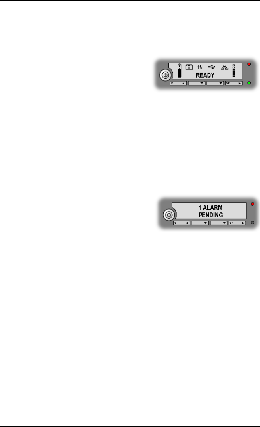
Chapter 6: Maintenance and troubleshooting
98-122988-DraftB6 146
Status signaling
There are many ways of troubleshooting if an error occurs. The EXPLORER™ 700 has different
means of status signaling, to help you find the cause of a problem:
•Indicators.
The function of the light indicators next to the
display is described in Light indicators on
page 9.
•Alarm messages.
•Log files.
Alarm messages and log files are described in the following sections.
Alarm messages
Display of alarm messages
The EXPLORER™ 700 can detect errors during POST (Power On Self Test) or CM (Continuous
Monitoring). When the EXPLORER™ 700 detects an error that requires your action, it issues an
alarm.
When alarms are issued in your EXPLORER™ 700,
the display indicates the number of new alarms,
and the red message indicator is flashing.
You now have the following options:
•Press C to ignore the alarm message and
continue from where you were before the alarm was issued.
•Press OK to enter the alarm list showing all active alarms. The alarms are listed with their ID
numbers.
To see the name and time stamp of the alarm, press OK again.
Use S and T to scroll through the name, ID and time stamp. If the text is too long, press OK
(X) to scroll through the rest of the text.
As long as the cause of an alarm is still present, the Main screen shows VIEW ALARM LIST?
If you press OK, the list of currently active alarms appears.
Explanations for the alarms and remedies to solve the problems are listed in the next section.
All alarms are logged in the alarm log. For information on the alarm log, see Alarm log on
page 152.

Chapter 6: Maintenance and troubleshooting
98-122988-DraftB6 147
List of alarms
The following list explains the alarms that may show in the display and in the web interface of the
EXPLORER™ 700.
Note In the display and in the web interface the ID includes a hyphen followed by a control-
digit at the end. This digit is used to make sure the ID is not misinterpreted when passed
on, e.g. to service personnel. Make sure you include the entire number when contacting
your distributor.
ID Alarm Text Explanation Remedy
00101 to
00199
System Data
Damaged
Important system data is
damaged
Do not use the
EXPLORER™ 700. Contact
your distributor.
00201 to
00209
Battery
Error
Error during communication
with the battery
Only use the
EXPLORER™ 700 with
external power supply.
Contact your distributor.
00211 to
00219
SIM Module
Error
The SIM interface on the
EXPLORER™ 700 cannot be
used.
Contact your distributor.
00221 to
00229
USB Module
Error
The USB interface on the
EXPLORER™ 700 cannot be
used.
Contact your distributor.
00231 to
00239
Temperature
Sensor FATAL
The system is in danger of
overheating.
Do not use the
EXPLORER™ 700. Contact
your distributor.
00241 to
00249
Temperature
Sensor Error
Automatic adjustment of the
display contrast does not
work.
Contact your distributor.
00251 to
00259
Bluetooth
Module Error
Bluetooth cannot be used. Contact your distributor.
00261 to
00269
System Error The EXPLORER™ 700 cannot
communicate on the satellite
network.
Contact your distributor.
00271 to
00279
Voice Module
Error
Voice services cannot be
accessed by the
EXPLORER™ 700
Contact your distributor.

Chapter 6: Maintenance and troubleshooting
98-122988-DraftB6 148
00281 to
00289
Ethernet
Module Error
The Ethernet interface on the
EXPLORER™ 700 cannot be
used.
Contact your distributor.
00291 to
00299
Power Supply
Error
Power on/off, charging
and/or LED control may be
out of function.
Contact your distributor.
00301 to
00309
GPS Module
Error
The GPS module is out of
function. The
EXPLORER™ 700 cannot
obtain a valid GPS position.
Contact your distributor.
00311 WLAN module
error
The WLAN interface on the
EXPLORER™ 700 cannot be
used.
Contact your distributor.
01000 Temperature
Too Low
Low ambient temperature is
causing the performance of
the EXPLORER™ 700 to be
degraded or halted.
Move the EXPLORER™ 700 to
a warmer location.
For information on
temperature limits, see
General specifications on
page 153.
01100 Temperature
Too High
High ambient temperature is
causing the performance of
the EXPLORER™ 700 to be
degraded or halted.
Move the EXPLORER™ 700 to
a cooler location.
For information on
temperature limits, see
General specifications on
page 153.
01200 Battery
Level Low
The battery is running out of
power.
Recharge the battery or
replace it with a new one.
ID Alarm Text Explanation Remedy

Chapter 6: Maintenance and troubleshooting
98-122988-DraftB6 149
01300 No GPS Fix The GPS receiver has not yet
achieved position fix.
Make sure the view to the
GPS satellites is not blocked.
To help the EXPLORER™ 700
obtain GPS fix, it should be
placed flat on an even
surface pointing straight
upwards, with a clear view to
as much of the sky as
possible.
Note that in some cases it
may take up to 10 minutes to
obtain GPS fix.
01400 Satellite
Signal Lost
The EXPLORER™ 700 no
longer receives a signal from
the satellite.
Make sure the
EXPLORER™ 700 has a clear
view to the satellite.
Check that the antenna is
pointed according to the
position data. Adjust the
position to the highest
possible signal strength.
01500 SIM Card
Missing
No SIM card is detected in
the SIM slot.
Insert SIM card.
If the SIM card is already
inserted, try removing and
reinserting it.
01600 SOS Calls
Only
The SIM card is not accepted
by the network. Only
emergency calls are allowed.
Enter the PIN and wait for
network approval. If the
problem persists, contact
your Airtime Provider.
01700 Registration
For Voice
Failed
The EXPLORER™ 700 has not
yet been allowed to register
for voice services (Circuit
Switched).
If the problem persists,
contact your Airtime
Provider.
01800 Registration
For Data
Failed
The EXPLORER™ 700 has not
yet been allowed register for
data services (Packet
Switched).
If the problem persists,
contact your Airtime
Provider.
ID Alarm Text Explanation Remedy

Chapter 6: Maintenance and troubleshooting
98-122988-DraftB6 150
01900 Temperature
Too Low For
Charging
The temperature is too low
for the battery charger to
operate.
If charging is needed, move
the EXPLORER™ 700 to a
warmer location. The
temperature must be above
0°C/+32°F for the battery
charger to operate.
02000 Satellite
Signal Weak
The signal from the satellite
is weak.
Check the line of sight to the
satellite. Be aware that
window glass may reduce
the signal level.
Check that the antenna is
pointed according to the
position data. Adjust the
position to the highest
possible signal strength.
02100 Ciphering
Off
The network has turned
ciphering off.
Do not transmit data that
requires ciphering.
02200 Ethernet
Connection
Failed
Ethernet data session could
not be established.
See the display call log for
the cause of the error. Refer
to Calls menu on page 38.
If the problem persists,
contact your distributor.
02300 External
Antenna
Failure
The EXPLORER™ 700 is not
able to detect the external
antenna type.
The reason may be one of the
following:
• You are not using an
original Thrane &
Thrane antenna
• The antenna is defective
Correct communication with
the satellite requires an
original Thrane & Thrane
antenna.
If you are already using an
original Thrane & Thrane
antenna when you see this
alarm, contact your
distributor for support.
ID Alarm Text Explanation Remedy

Chapter 6: Maintenance and troubleshooting
98-122988-DraftB6 151
02400 Invalid
Battery
The EXPLORER™ 700 is not
able to detect the battery
type.
The reason may be one of the
following:
• You are not using an
original Thrane &
Thrane battery
• The battery is defective
The EXPLORER™ 700
requires an original Thrane
& Thrane battery.
If you are already using an
original Thrane & Thrane
battery when you see this
alarm, contact your
distributor for support.
02600 Antenna
Failure
The EXPLORER™ 700 is not
able to detect the state of the
antenna relay.
Do not use the terminal.
Contact your distributor.
02800 Bluetooth
Device
Database
Full
The list of paired Bluetooth
devices is full. The
EXPLORER™ 700 does not
allow more than 7 paired
devices.
Unpair a paired device to
make room for a new one.
For information on how to
unpair devices, see
Unpairing devices on
page 117.
ID Alarm Text Explanation Remedy

Chapter 6: Maintenance and troubleshooting
98-122988-DraftB6 152
Log files
Note
When contacting Thrane & Thrane for support, please include a diagnostic report.
The diagnostic report contains information relevant for the service personnel during
troubleshooting.
To generate the diagnostic report, access the web interface and select Help Desk. Then click
Generate report.
Alarm log
The alarm log holds information of all alarms issued by the EXPLORER™ 700.
The log includes the time of the error, a short description, location of the error etc. This
information can help troubleshooting errors in the EXPLORER™ 700. The Alarm log is not
accessible from the user interface, but is included when you generate a diagnostic report. For
information, see Help desk and diagnostic report on page 132.
Call log
The call log holds information of up to 100 calls and data sessions to/from the EXPLORER™ 700.
The call log contains detailed information such as date, time, phone numbers, duration, Mb
transferred etc., for each call or data session.
Date and time is UTC time, received from the satellite.
For information on how to view the call log in the display, see Calls menu on page 38.
For information on how to view the call log in the web interface, see Viewing the lists of calls on
page 92.
Note The call log in the display shows information on voice calls but not on data sessions.

98-122988-DraftB6 153
Appendix A
Technical specifications A
In this appendix
This appendix contains technical specifications for the EXPLORER™ 700 and information on
Conformity.
General specifications
The EXPLORER™ 700 meets or exceeds current and proposed Inmarsat specifications for operation
on the Inmarsat Broadband Global Area Network.
Item Specification
Type EXPLORER™ 700, BGAN Class 1 Terminal
Max. IP data rate, Rx/Txa
Streaming IP
492 kbps/492 kbps (simultaneously)
32, 64, 128, 256 kbps
Physical dimensions
Total
Antenna
Transceiver
297 mm x 399 mm x 51 mm/11.7” x 15.7” x 2.0”
297 mm x 399 mm x 51 mm/11.7” x 15.7” x 2.0”
280 mm x 228 mm x 40 mm/11.0” x 8.9” x 1.6”
Weight
Total
Antenna
Transceiver with battery
3.2 kg/7.0 lbs
1.7 kg/3.7 lbs
1.5 kg/3.3 lbs
Environmental conditions
Operating temperature
Powered by external DC
Powered from battery
Storage temperature
Without battery
With battery
Relative humidity
Water & Dust
Transceiver
Antenna
Max. wind-load
-25°C to +55°C/-13°F to +131°F
0°C to +55°C/+32°F to +131°F
-40°C to +80°C/-40°F to +176°F
-20°C to +60°C/-4°F to +140°F
95% non-condensing at +40°C/+104°F
IP-52
IP-66
18 m/s or 59 ft/s (Operational)

Appendix A: Technical specifications
98-122988-DraftB6 154
Battery
Specifications
Robustness 0.5 m/1.64 ft drop on concrete (Operational, 95% survival)
Supported web browsers
(Other browsers may be
supported as well, but only
these have been tested.)
Microsoft Internet Explorer 6.0
Mozilla Firefox 1.0
Apple Safari 2.0
a. Performance depends on a wide range of factors and actual usage.
Item Specification
Item Specification
Battery type Lithium ion, rechargeable
Voltage 11.1 V
Capacity 4.4 Ah
Time between recharging
Standby time
Tx time, max
Rx time, max
36 hours at 25°C/77°F
2hours30minutes @ 144kbps (158MB), 25°C/77°F
1 hour 30 minutes @ 492 kbps (324 MB), 25°C/77°F
3 hours 30 minutes @ 492 kbps (756 MB), 25°C/77°F
Charge timea
a. Performance depends on a wide range of factors and actual usage.
2 hours 30 minutes
Charge temperature 0°C to +45°C/+32°F to +113°F Ambient
Min. charge cycles 300
Storage temperature
1Month
3Months
1Year
-20°C to +60°C/-4°F to +140°F Ambient
-20°C to +45°C/-4°F to +113°F Ambient
-20°C to +20°C/-4°F to +68°F Ambient

Appendix A: Technical specifications
98-122988-DraftB6 155
Power input
Connector pin-out
This drawing shows the pin-out for the DC power
connector.
Specifications
AC/DC adapter, FSP 065-AAC
SIM interface
USIM #1 Specifications
USIM #2 Specifications
USIM #2 is reserved for future use.
+
GND
Item Specification
DC input range +10 to +32 V DC
Power consumptiona
Standby mode
Transmit mode
During charging
a. Performance depends on a wide range of factors and actual usage.
1.2 W (Typical)
18 W (Typical)
60 W max.
Connector type 2.5/5.5mm power jack, Switch craft RAPC 712
Item Specification
AC input range 100 to 240 V AC, 47 to 63 Hz, 65 W
DC output 19 V DC
Item Specification
Slot type Standard SIM card holder

Appendix A: Technical specifications
98-122988-DraftB6 156
Phone interface, 2-port
Connector pin-out
The pin-out for the Phone connectors is as follows:
Specifications
Pin Function
1NC
2Tip
3Ring
4NC
1234
RJ-11 Connector
Female (Receptacle)
Item Specification
Number of connectors 2
Connector type RJ-11, female
Impedance 180 Ω + 750 Ω/150nF
Max. cable length 100 m/80 Ω
Max. units connected Two units, one in each connector
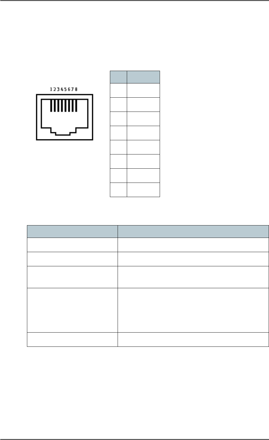
Appendix A: Technical specifications
98-122988-DraftB6 157
ISDN interface, 2-port
Connector pin-out
The pin-out for the ISDN connectors is as follows:
Specifications
Pin Function
1NC
2NC
3Rx+
4Tx+
5Tx—
6Rx—
7NC
8NC
RJ-45 Connector
Female (Receptacle)
Item Specification
Number of connectors 2
Connector type RJ-45, female
Max. number of units per
interface
8 (Max. total power supplied: 1 W)
Data rate
Voice
Data
Audio
4 kbps
64 kbps
3.1 kHz
Max. cable length 100 m
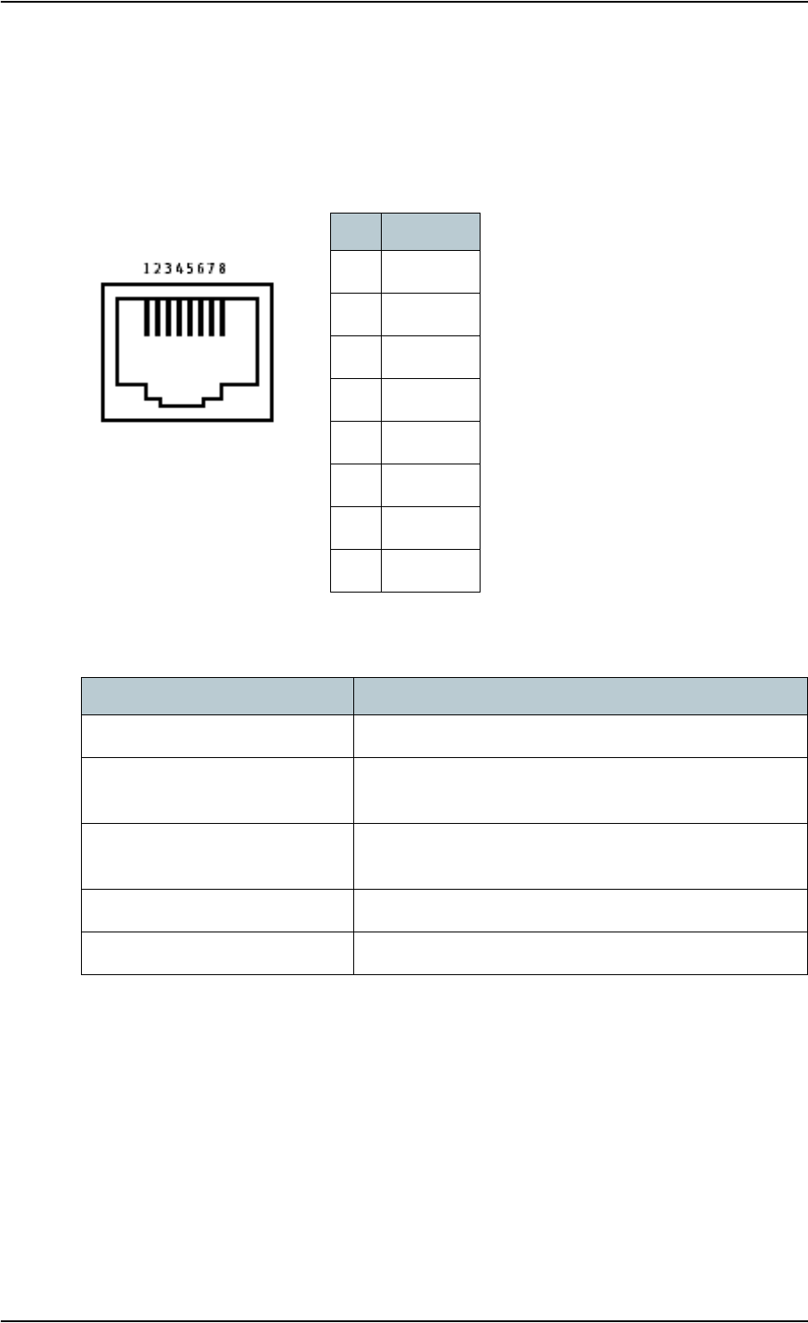
Appendix A: Technical specifications
98-122988-DraftB6 158
LAN interface, 2-port
Connector pin-out
The pin-out for the LAN connectors is as follows:
Specifications
Pin Function
1Rx +
2Rx —
3Tx +
4NC
5NC
6Tx —
7NC
8NC
RJ-45 Connector
Female (Receptacle)
Item Specification
Number of connectors 2
Connector type RJ-45, female, Auto cross-over MDI/MDI-X
(IEEE 802.3 10/100BaseT)
Standard ISO/IEC 8877:1992 and
IEEE 802.3 1998 Edition
Max. data rate 10/100 Mbps
Max. cable length 100 m/328 ft with Cat5 UTP
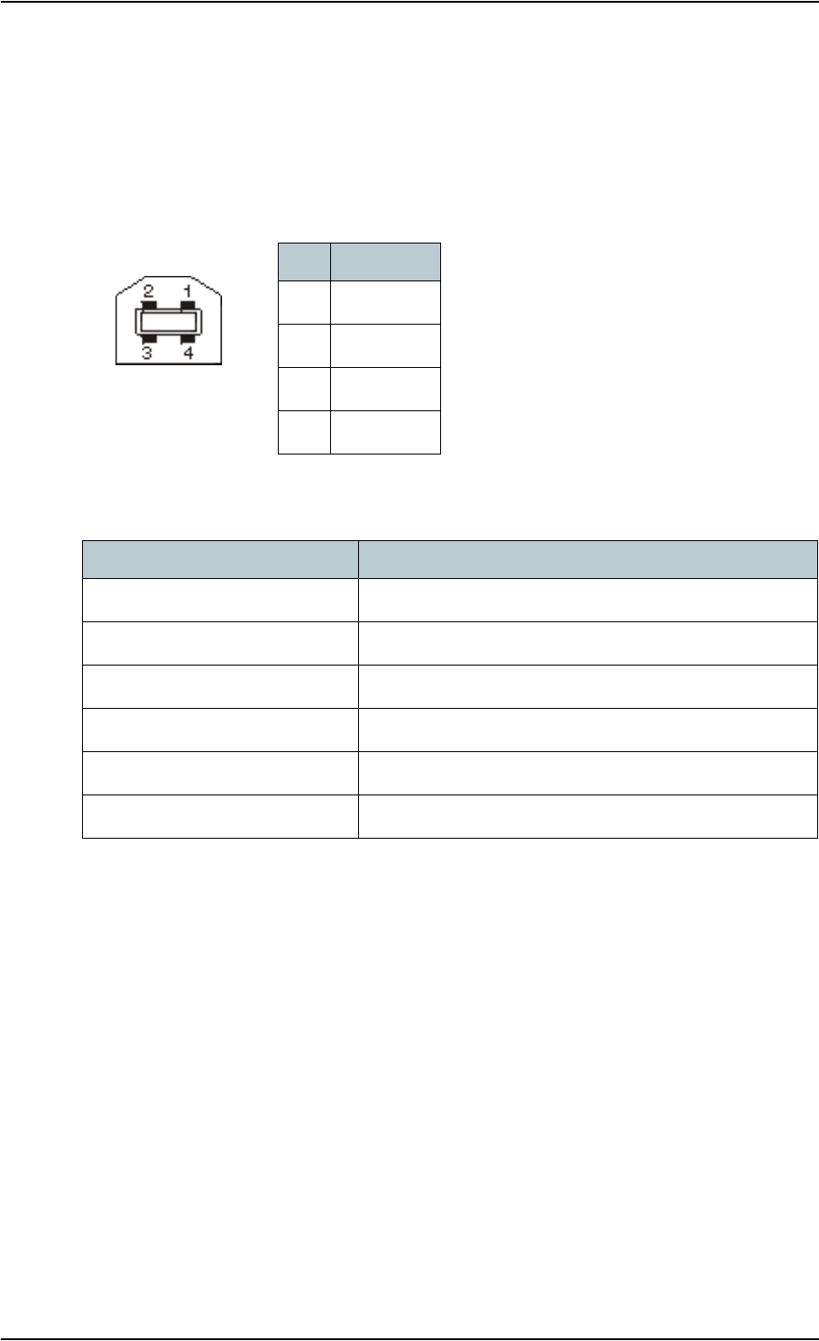
Appendix A: Technical specifications
98-122988-DraftB6 159
USB interface
Connector pin-out
The pin-out for the USB connector is as follows:
Specifications
Pin Function
1+5VDC
2D —
3D +
4GND
Type B
Female (Receptacle)
Item Specification
Version 1.1 (Slave)
Connector type B, female
Max. data rate 12 Mbps
Max. cable length 5 m/16.4 ft
Max. units connected 7 physical devices
Driver Proprietary, enclosed on CD with the product

Appendix A: Technical specifications
98-122988-DraftB6 160
WLAN Access Point
Specifications
Item Specification
Standard IEEE 802.11 a/b/g
Antenna Dual space diversity antennas integrated in transceiver
unit
Frequencies 2.4 GHz (802.11b/g) or
5 GHz (802.11a)
Max. coverage outdoora
a. Performance depends on a wide range of factors and actual usage.
100 m/328 ft
Max. data ratea54 Mbps

Appendix A: Technical specifications
98-122988-DraftB6 161
Bluetooth interface
Specifications
Item Specification
Version 1.2
Standard Power Class 1.
The Class 1 interface also supports Class 2 and Class 3
peripherals if they support RSSI (Received Signal Strength
Indicator).
Antenna Integrated in transceiver unit
Physical media Frequency-Hopping Spread Spectrum RF
Max. data rate 721 kbps + 57.6 kbps
Frequency 2400 to 2483.5 MHz
Max. coverage outdoora
a. Performance depends on a wide range of factors and actual usage.
100 m/328 ft
Max. number of devices
connected
7
Profiles supported Cordless Telephony Profile (CTP)
Serial Port Profiles (SPP):
• Dial-up Networking (DUN)
• LAN Access Profile (LAP)
• Headset Profile (HSP)

Appendix A: Technical specifications
98-122988-DraftB6 162
Antenna interface on Transceiver
Connector pin-out
This drawing shows the antenna connector
on the transceiver.
Specifications
Signal
GND
Item Specification
Connector type TNC, female
Max. cable length 100 m/328ft, single cable, 50 Ω
Max. cable loss 1.4 Ω totala/20 dB @ 1.5 GHz
a. Note that this is the sum of the inner conductor resistance and the GND shield resistance.
Max. current rating for cables 2.5 A

Appendix A: Technical specifications
98-122988-DraftB6 163
Detachable antenna
Connector pin-out
This drawing shows the connector on the
detachable antenna of the EXPLORER™ 700.
Specifications
Signal
GND
Item Specification
Type Directional patch array, manually adjustable
Polarization RHCP
Connector type QN, female
Frequencies
Inmarsat
Transmit
Receive
Bearer bandwidth
GPS
1626.5 to 1660.5 MHz
1525.0 to 1559.0 MHz
200 kHz
1575.42 MHz
EIRP 20 dBW ±1 dB

Appendix A: Technical specifications
98-122988-DraftB6 164
EXPLORER™ Bluetooth Handset charger interface
Connector pin-out
This drawing shows the connector for the EXPLORER™
Bluetooth Handset charging interface.
Pin 1 is the pin closest to the coding projection on the
plastic insert.
Specifications
Pin 2,Pin 1,
6.4 V GND
Item Specification
Connector type Proprietary
Output 6.4 V/350 mA
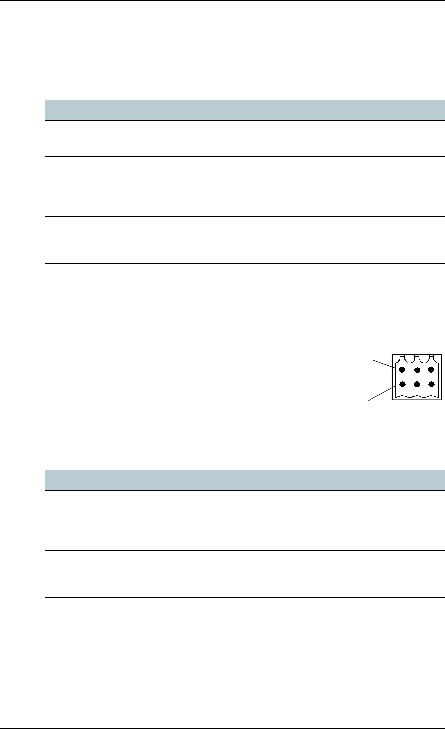
Appendix A: Technical specifications
98-122988-DraftB6 165
Solar panel interface
Specifications
I/O interface
Connector pin-out
This drawing shows the connector for the Input/Output interface.
Specifications
Item Specification
Connector type DC input connector
(for pin-out, see Power input on page 155)
Solar panel type 12 V unregulated solar panels, built-in Maximum Power
Point Tracking for solar panel regulation.
Max. open circuit voltage 32 V
Max. Power Point voltage 28 V
Suitable power range 5 W to 100 W (a good selection will be 35 W to 40 W)
3 Input/Output
3 GND
Item Specification
Connector type 1 TT31-203302-403,
S2L SMT 3.5/6/90G, Weidmuller 1794210000
Function 3 input/output
Input TTL-level, voltage 0 V to 32 V
Output Sinking current max. 50 mA, voltage 0 V to 32 V
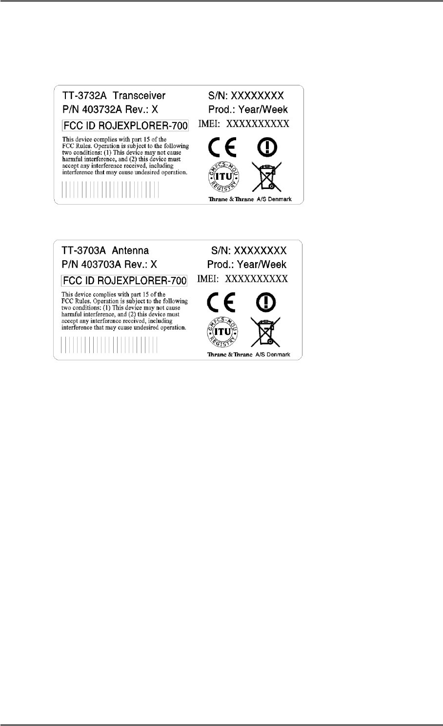
Appendix A: Technical specifications
98-122988-DraftB6 166
Serial number labels
The following label is placed on the transceiver part of the EXPLORER™ 700.
The following label is placed on the antenna part of the EXPLORER™ 700.
“Xes” are replaced by the relevant numbers for the specific transceiver/antenna.

Appendix A: Technical specifications
98-122988-DraftB6 167
Conformity
CE (R&TTE)
The EXPLORER™ 700 is CE certified (R&TTE directive) as stated in “Declaration of Conformity with
R&TTE Directive”, enclosed in electronic copy on the next page.
WLAN: The WLAN interface is CE certified through the manufacturer of the WLAN card.
Use of Bluetooth:
Thrane & Thrane have sent notification to all countries in the EU for use of the Bluetooth interface.
Individual license may be required in some countries outside the EU and USA.
For use in the EU, the following restrictions apply:
France: Outdoor use must be limited to 10 mW EIRP within the frequency band 2454 MHz to
2483.5 MHz.
Italy: Outdoor use outside own premises require general authorization
FCC
This device complies with part 15 of the FCC Rules. Operation is subject to the following two
conditions:
1. This device may not cause harmful interference, and
2. this device must accept any interference received, including interference that may cause
undesired operation.
Part 15.21
Changes or modifications not expressly approved by the party responsible for compliance could
void the user’s authority to operate the equipment.
See also FCC Caution and FCC Radiation Exposure statement at the beginning of this manual.
GMPCS
The EXPLORER™ 700 has obtained the GMPCS-MoU mark.
Note The manufacturer is not responsible for any radio or TV interference caused by
unauthorized modifications to this equipment. Such modifications could void the user’s
authority to operate the equipment.

Appendix A: Technical specifications
98-122988-DraftB6 168
REPLACE THIS PAGE IN THE PDF FILE WITH THE DECLARATION OF CONFORMITY

98-122988-DraftB6 169
Appendix B
AT commands B
In this appendix
This appendix contains a list of AT Commands for the EXPLORER™ 700.
Starting up an AT command session
Set up your computer to use either the USB or Bluetooth interface. For further information, see
Using the USB interface on page 69 or Using a computer with Bluetooth on page 73.
Connect your computer to the USB or Bluetooth interface of the EXPLORER™ 700 and launch your
terminal program.
The following section contains a list of commands that can be used with the EXPLORER™ 700. For
further information on the AT commands, refer to the following standards:
•ITU V.250 Serial asynchronous automatic dialing and control
•3GPP TS 27.005 ver. 4.2.0, Use of Data Terminal Equipment — Data Circuit terminating
Equipment (DTE-DCE) interface for Short Message Service (SMS) and Cell Broadcast Service
(CBS)
•3GPP TS 27.007 ver. 4.6.0, AT command set for User Equipment (UE)
3GGP standards are found on www.3gpp.org
ITU standards are found on www.itu.int

Appendix B: AT commands
98-122988-DraftB6 170
List of supported AT commands
Command Function
ATA Answer
ATD Dial
ATE Command echo
ATH Hang up
ATI Request identification information
ATL Monitor speaker loudness
ATM Monitor speaker mode
ATN Automode control
ATP Select pulse dialing (command)
ATQ Result code suppression
ATS Set register
ATT Select tone dialing (command)
ATV DCE response format
ATX Result code selection and call progress monitoring control
ATZ Reset to default configuration
AT&C Circuit 109 (Received line signal detector) behavior
AT&D Circuit 108 (Data terminal ready) behavior
AT&F Set to factory defined configuration
AT&V Display active and stored profile
AT&W Store profile
AT+CACM Accumulated call meter
AT+CAEMLPP eMLPP priority registration and interrogation
AT+CALM Alert sound mode
AT+CAMM Accumulated call meter
AT+CAOC Advice of charge

Appendix B: AT commands
98-122988-DraftB6 171
AT+CBC Battery charge
AT+CBST Select bearer service type
AT+CCFC Call forwarding number and conditions
AT+CCLK Clock
AT+CCUG Closed user group
AT+CCWA Call waiting
AT+CCWE Call meter maximum event
AT+CDIP Called line identification presentation
AT+CEER Extended error report
AT+CFCS Fast call setup conditions
AT+CFUN Set phone functionality
AT+CGACT PDP context activate or deactivate
AT+CGATT PS attach or detach
AT+CGCLASS GPRS mobile station class
AT+CGCMOD PDP context modify
AT+CGDATA Enter data state
AT+CGDCONT Define PDP context
AT+CGDSCONT Define secondary PDP context
AT+CGEQMIN 3G quality of service profile (minimum acceptable)
AT+CGEQNEG 3G quality of service profile (negotiated)
AT+CGEQREQ 3G quality of service profile (requested)
AT+CGEREP Packet domain event reporting
AT+CGMI Request manufacturer identification
AT+CGMM Request model identification
AT+CGMR Request revision identification
AT+CGPADDR Show PDP address
Command Function

Appendix B: AT commands
98-122988-DraftB6 172
AT+CGQMIN Quality of service profile (minimum acceptable)
AT+CGQREQ Quality of service profile (requested)
AT+CGREG GPRS network registration status
AT+CGSMS Select service for MO SMS messages
AT+CGSN Request product serial number identification
AT+CGTFT Traffic flow template
AT+CHLD Call related supplementary services
AT+CHUP Hang-up call
AT+CIMI Request International Mobile Subscriber Identity
AT+CIND Indicator control
AT+CLAC List all available AT commands
AT+CLCC List current calls
AT+CLCK Facility lock
AT+CLIP Calling line identification presentation
AT+CLIR Calling line identification restriction
AT+CMAR Master reset
AT+CMEC Mobile equipment control mode
AT+CMEE Report mobile equipment error
AT+CMER Mobile equipment event reporting
AT+CMGC Send command
AT+CMGD Delete message
AT+CMGF Message format
AT+CMGL List messages
AT+CMGR Read messages
AT+CMGS Send message
AT+CMGW Write message to memory
Command Function

Appendix B: AT commands
98-122988-DraftB6 173
AT+CMOD Call mode
AT+CMSS Send message from storage
AT+CNMI New message indication to TE
AT+CNUM Subscriber number
AT+COLP Connected line identification presentation
AT+COPN Read operator names
AT+COPS PLMN selection
AT+CPAS Phone activity status
AT+CPBF Find phone book entries
AT+CPBR Read phone book entries
AT+CPBS Select phone book memory storage
AT+CPBW Write phone book entry
AT+CPIN Enter PIN
AT+CPLS Selection of preferred PLMN list
AT+CPMS Preferred message storage
AT+CPOL Preferred PLMN list
AT+CPPS eMLPP subscriptions
AT+CPUC Price per unit and currency table
AT+CPWD Change password
AT+CR Service reporting control
AT+CRC Cellular result codes
AT+CREG Network registration
AT+CRSM Restricted SIM Access
AT+CSCA Service center address
AT+CSCS Select TE character set
AT+CSDF Settings date format
Command Function

Appendix B: AT commands
98-122988-DraftB6 174
AT+CSIL Silence command
AT+CSMS Select message service
AT+CSQ Signal quality
AT+CSSN Supplementary service notifications
AT+CSTA Select type of address
AT+CSTF Settings time format
AT+CSVM Set voice mail number
AT+CUSD Unstructured supplementary service data
AT+CAAP Automatic answer for eMLPP Service
AT+FCLASS Select mode
AT+GCAP Request complete capabilities list
AT+GCI Country of Installation
AT+GMI Request manufacturer identification
AT+GMM Request model identification
AT+GMR Request revision identification
AT+GSN Request product serial number identification
AT+ICF DTE DCE character framing
AT+IFC DTE-DCE local flow control
AT+ILRR DTE-DCE local rate reporting
AT+IPR Fixed DTE rate
AT+WS46 PCCA STD-101 [17] select wireless network
AT_IBLTH Bluetooth management
AT_IBNOTIFY Control the sending of unsolicited result codes
AT_IBTIF Bluetooth configuration
AT_IBTINQ Bluetooth inquiry management
AT_IGPS GPS location information
Command Function

Appendix B: AT commands
98-122988-DraftB6 175
AT_ILOG Retrieve log file from the EXPLORER™ 700
AT_IMETER Call metering
AT_INIS Network interface status
AT_IPOINT Antenna pointing
AT_ISIG Signal quality indication
AT_ITCSI Configure incoming voice quality
AT_ITCSO Configure outgoing voice quality
AT_ITEMP Temperature in the EXPLORER™ 700
AT_ITISDN ISDN Configuration
AT_ITMSN Configuration of MSN numbers to an interface/call type
AT_ITMSNLIST Return valid MSN numbers for the interfaces
AT_ITNAT Configure NAT for an interface
AT_ITWLAN WLAN Configuration
AT_ITWLANCC WLAN Country Code
AT_ITWLANF WLAN Filters
AT_ITWLANMAC WLAN MAC Address
Command Function

98-122988-DraftB6 176
Glossary
Glossary
A
APN Access Point Name. The Access Point Name is used by the EXPLORER™ 700 user to
establish the connection to the required destination network.
B
BGAN Broadband Global Area Network. A satellite network based on geostationary
satellites, delivering data rates of up to 492 kbps to virtually any part of the earth,
with full UMTS (3G) compatibility.
C
CE Conformitée Européenne. This term signifies that a CE certified product conforms to
European health, environmental, and safety regulations. In short, it makes the
product legal to be sold in the European Union.
CID Context IDentifier
D
DHCP Dynamic Host Configuration Protocol. A protocol for assigning dynamic IP addresses
to devices on a network. With dynamic addressing, a device can have a different IP
address every time it connects to the network.
E
EIRP Effective Isotropic Radiated Power. EIRP is the apparent power transmitted towards
the receiver, if it is assumed that the signal is radiated equally in all directions.
F
FCC Federal Communications Commission. An independent United States government
agency, directly responsible to Congress. FCC certification is normally required to
make a product legal to be sold in the United States.

Glossary
98-122988-DraftB6 177
G
Geostationary Placed in a fixed position relative to a point on the surface of the earth.
GMPCS Global Mobile Personal Communications by Satellite. GMPCS is a personal
communication system providing transnational, regional or global coverage from
satellites.
GMPCS-MoU A framework signed by Member States, GMPCS System Operators, Terminal
Manufacturers and Service Providers. The GMPCS-MoU mark allows GMPCS
subscribers to take terminals anywhere and use them in countries where they are
licensed.
GPRS General Packet Radio Service. A standard for wireless communications which runs at
speeds up to 115 kbps, compared with current GSM (Global System for Mobile
Communications) systems’ 9.6 kbps.
GPS Global Positioning System. A system of satellites, computers, and receivers that is
able to determine the latitude and longitude of a receiver on Earth by calculating the
time difference for signals from different satellites to reach the receiver.
I
IMEI International Mobile Equipment Identity. A unique number given to every single
piece of mobile phone equipment. IMEI numbers are stored in a database containing
all valid mobile phone equipment.
IMSO International Maritime Satellite Organisation. An intergovernmental body
established to ensure that Inmarsat continues to meet its public service obligations,
including obligations relating to the GMDSS.
ISDN Integrated Services Digital Network. An international communications standard for
sending voice, video, and data over digital telephone lines or normal telephone
wires. ISDN supports data transfer rates of 64 kbps.
ISP Internet Service Provider
K
kbps kilobits per second
L
LaunchPad LaunchPad is a PC application used to control terminals in the BGAN system.
LaunchPad is provided on the Inmarsat CD-ROM supplied with your EXPLORER™
700. Use of the LaunchPad is described in the user guide on the same CD-ROM.

Glossary
98-122988-DraftB6 178
M
MAC Media Access Control address. A hardware address that uniquely identifies each
node of a network.
N
NAT Network Address Translation. An Internet standard that enables a local-area
network to use one set of IP addresses for internal traffic and a second set of
addresses for external traffic. A NAT module makes all necessary address
translations.
NC Not Connected
P
Pairing Bluetooth Pairing happens when two Bluetooth enabled devices agree to
communicate. The two devices exchange passkeys and join what is called a trusted
pair. In a trusted pair, the two devices automatically accept communication with each
other.
Passkey A unique code or password used when pairing Bluetooth devices.
PCB Printed Circuit Board
PDA Personal Digital Assistant. A lightweight, hand-held, usually pen-based computer
used as a personal organizer.
PDP Packet Data Protocol. A network protocol used by external packet data networks that
communicate with a GPRS network.
PIN Personal Identification Number. A code number used to provide access to a system
that has restricted access.
PUK PIN Unblocking Key. An eight-digit code used to unblock a SIM card after three
incorrect PINs have been entered. The PUK code is supplied with the SIM card.
R
RDI Restricted Digital Information
RHCP Right-Hand Circular Polarization
RSSI Received Signal Strength Indicator

Glossary
98-122988-DraftB6 179
S
SAS Satellite Access Station. The gateway between the satellites and the worldwide
networks such as Internet, telephone network, cellular network etc.
SDU Service Data Unit. Also known as a data packet.
SIM Subscriber Identity Module.The SIM provides secure storing of the key identifying a
mobile phone service subscriber but also subscription information, preferences and
storage of text messages.
SSID Service Set IDentifier. An SSID is the name of a wireless local area network (WLAN).
All wireless devices on a WLAN must use the same SSID in order to communicate with
each other.
Streaming A technique for transferring data — such as audio or video clips — so that it is
processed as a continuous stream. With a Streaming connection you are charged by
the minute, like for a telephone connection.
T
TFT Traffic Flow Template. A packet filter list allowing the Core network and the
EXPLORER™ 700 to classify packets received from the external network into the
proper PDP context.
U
UDI Unrestricted Digital Information. A transparent 64 kbps data channel.
USB Universal Serial Bus. An interface standard for communication between a computer
and external peripherals over an inexpensive cable using biserial transmission.
Mostly used with keyboards, mice, monitors and printers.
V
VPN Virtual Private Network. A network that is constructed by using public wires to
connect nodes. You can create networks using the Internet for transporting data,
using security mechanisms so that only authorized users can access the network.
W
WLAN Wireless Local Area Network. A type of local-area network that uses high-frequency
radio waves rather than wires to communicate between nodes.

98-122988-DraftB6 180
Index
Index
Numerics
2-wire interface
connecting, 53
setting voice quality, 118
specifications, 156
64 kbps UDI using USB, 70
A
accessories available, 136
administration settings, 124
advanced configuration
Bluetooth, 113
LAN, 107
network settings, 120
USB, 105
WLAN, 110
alarms
in display, 45, 146
list of active, 44, 123
antenna
cables available, 136
connecting, 76
connectors, 18
detaching, 14
for Bluetooth, 161
for WLAN, 160
pointing, 26
pole mount kit for, 136
repointing, 39, 88
safety, iv
specifications, 163, 164
APN
setting for all interfaces, 120
setting for Bluetooth, 114
setting for LAN, 107
setting for USB, 105
applications overview, 7
AT commands, 169
audio indicators, 39, 100
audio quality, 51
automatic power up, 40, 99
Azimuth, 24
B
backlight in display, 39, 100
battery
charging, 134
guidelines for use, 134
inserting, 15
removing, 16
specifications, 154
BGAN
coverage, 3
services, 5
system overview, 4
Bluetooth devices
pairing, 115
unpairing, 117
viewing list of paired, 117
Bluetooth handset
charging interface, 79, 164
making a call, 57
Bluetooth interface
connecting a computer, 73
setting up, 113
setting voice quality, 113
specifications, 161
browser settings
for web interface, 81
C
call log, 38, 99
call type, 51
setting for Bluetooth, 113
setting for ISDN, 119
setting for Phone/Fax interface, 118
calls
holding, 61
local, 59
making or receiving, 57
missed, received, outgoing, 38, 92
redial, 58
to the EXPLORER™ 700, 58
view ongoing, 87
waiting indication, 61
CE compliance, 167
certification, 167
clearing logs, 126

Index
98-122988-DraftB6 181
clearing usage counter, 126
common network settings, 120
compliance, 167
configuration
Bluetooth, 113
exporting to file, 125
import from file, 126
ISDN, 119
LAN, 107
USB, 105
WLAN, 110
conformity, 167
connectors
Bluetooth handset charging, 164
I⁄O interface, 165
ISDN, 157
LAN, 158
overview, 18
Phone, 156
power, 155
USB, 159
contact information, 133
contrast in display, 39, 100
coverage
Inmarsat BGAN system, 3
D
dashboard, 86
data
advanced configuration, 120
Profiles, 127
Traffic Flow Templates, 130
data sessions
view ongoing, 87
delivery
items included, 12
DHCP
enable or disable for LAN, 107
display
backlight, 39, 100
contrast, 39, 100
menu drawing, 33
navigating, 36
overview of menus, 32
short-cuts, 36
symbols, 35
disposal, 135
distributors, 133
E
Elevation, 24
Ethernet interface
connecting, 66
setting up, 107
specifications, 158
EXPLORER™ 700
getting to know, 8
type number, ii
export configuration, 125
F
fax
sending or receiving, 63
FCC compliance, 167
features, 6
G
general specifications, 153
GMPCS compliance, 167
GPS
antenna, 10
frequency, 163
obtaining GPS fix, 25
position, 42
troubleshooting, 139
view status, 42
H
hardware
view version, 87, 121
Header compression
enable or disable for Bluetooth, 114
enable or disable for LAN, 107
help desk number, 44, 132
changing with web interface, 132
I
I⁄O interface
connecting, 78
specifications, 165
IMEI number, 43, 87, 121
import configuration, 126

Index
98-122988-DraftB6 182
Inbox for SMS messages
replying, forwarding or deleting, 96
indicators
function, 9
interfaces
turning on or off, 40, 49
interfaces and services
combinations, 11
internal calls, 59
IP address, 43, 87, 121
ISDN interface
connecting a computer, 72
connecting a phone or a fax, 54
setting call type, 119
setting up, 119
specifications, 157
ISDN using USB, 70
items included in delivery, 12
L
LAN interface
connecting, 66
setting up, 107
specifications, 158
LaunchPad, 47
LEDs
function, 9
light and sound
disabling, 40, 101
light indicators
function, 9
local phone call, 59
logs
clearing, 126
M
MAC address, 43, 87, 121
matrix of services and interfaces, 11
messages
configuring outgoing, 97
deleting in display, 37
forwarding, 96
opening in display, 37
opening in web interface, 96
receiving in display, 45
receiving in web interface, 95
replying, 96
sending, 95
view list in display, 37
mobile subscriber numbers
viewing, 43, 87, 121
N
NAT
setting on or off for LAN, 107
navigation
display and keypad, 36
web interface, 84
number of EXPLORER™ 700 terminal, ii
O
off-line
working with EXPLORER™ 700, 22
options available, 136
Outbox for SMS messages
resending or deleting messages, 94
P
paired Bluetooth devices
view list, 117
pairing Bluetooth devices, 115
phone
local call, 59
making calls, 57
phone book, 89
add number, 90
delete all entries, 90
delete entry, 90
modify entry, 90
Phone interface
connecting, 53
specifications, 156
Phone/Fax interface
setting voice quality, 118

Index
98-122988-DraftB6 183
PIN
administration PIN, 124
entering in display, 23
entering in web interface, 85
entering with a phone, 56
pointing, 26
help, 24
position data, 24
repoint the antenna, 39
sound on/off, 39, 100
POTS interface
connecting, 53
setting voice quality, 118
specifications, 156
power, 20
automatic, 40, 99
connecting, 19
specifications, 155
power up mode, 40, 99
Profiles
for data transmission, 127
selecting for Bluetooth, 114
selecting for LAN, 107
selecting for USB, 105
properties
view, 43, 87, 121
Proxy server
disabling, 81
PUK code, 23, 56, 85
Q
quality of voice, 51
Quick dial, 57
R
redial, 58
restoring settings, 41
S
safety summary, iii
sent messages
resending, forwarding or deleting, 94
viewing status, 94
serial number, 43, 87, 121
services
supported by BGAN, 5
services and interfaces
combinations, 11
settings
restore, 41
Short dial, 57
SIM card
inserting, 15
removing, 17
specifications, 155
SMS in display
opening or deleting, 37
receiving, 45
view list, 37
SMS in web interface
forwarding, 96
opening, 96
receiving, 95
replying to, 96
sending, 95
SMS service number, 87, 98, 121
software
uploading, 122
view version, 87, 121
sound
alarm, 39, 100
message, 39, 100
when pointing, 39, 100
sound and light
disabling, 40, 101
specifications
antenna, 164
Bluetooth handset charging interface, 164
Bluetooth interface, 161
Ethernet interface, 158
general, 153
I⁄O interface, 165
ISDN interface, 157
LAN interface, 158
Phone interface, 156
power, 155
SIM card, 155
USB interface, 159
WLAN interface, 160
Standard data, 65
start-up
options, 21
status
methods for signaling, 146
viewing, 46, 86

Index
98-122988-DraftB6 184
stealth mode
activating, 36
enabling, 40, 101
Streaming data, 65
activating, 38, 65
defining Profiles for, 127
support
contact information, 133
T
telephone interface
connecting, 53
specifications, 156
total usage
viewing, 87, 91
Traffic Flow Templates, 130
troubleshooting guide, 137
type number of EXPLORER™ 700 terminal, ii
typography used in this manual, v
U
UDI using USB, 70
unpairing Bluetooth devices, 117
uploading software, 122
usage counter, 87, 91
clearing, 126
USB interface
connecting, 69
setting up, 105
specifications, 159
V
version
hardware, 43, 87, 121
software, 43, 87, 121
voice mail number
viewing, 43, 98
voice quality, 51
setting for Bluetooth, 113
setting for ISDN, 119
setting for Phone/Fax interface, 118
W
web interface
accessing, 80
browser settings, 81
definition, 80
navigating, 84
wireless LAN interface
connecting, 68
setting up, 110
specifications, 160
WLAN interface
connecting, 68
setting up, 110
specifications, 160
interface, you can view the Dashboard of the EXPLORER 700 and upload software without
inserting a SIM card. Upload of software, however, requires an Administrator user name and
password.
SIM lock
The supplier may SIM lock the EXPLORER 700 to a specific provider. For further information,
contact your supplier.
What is BGAN?
The Broadband Global Area Network (BGAN) is a mobile satellite service that offers high-speed
data up to 492 kbps and voice telephony. BGAN enables users to access e-mail, corporate
networks and the Internet, transfer files and make telephone calls.
Coverage
The Inmarsat® BGAN services are based on geostationary satellites situated above the equator.
Each satellite covers a certain area (footprint). The coverage map below shows the footprints of the
BGAN system as they are after the repositioning of the satellites at the end of february 2009. For
updated information on coverage, see Inmarsat’s home page at www.inmarsat.com.
The map above shows Inmarsat’s expectations of coverage after repositioning of the I4
Note
satellites. The map does not represent a guarantee of service. The availability of service
at the edge of coverage areas may fluctuate.
98-122988-H
Chapter 1: Introduction
8
Спутниковый терминал BGAN Explorer 700 снят с производства. Замена — BGAN Explorer 710.
Терминал спутниковой связи BGAN Explorer 700 самый старший в семействе портативных носимых спутниковых терминалов компании Cobham. BGAN 700 сочетает в себе оптимальные характеристики с гибкими функциональными возможностями заключенными в прочную конструкцию терминала. Спутниковый терминал Explorer 700 заключает в себе множественные интерфейсы речевой связи и передачи данных, терминал поддерживает возможность присоединения к беспроводной локальной сети (WLAN), обеспечивая wi-fi доступ для нескольких пользователей одновременно.
Терминал BGAN 700 подключается к спутниковой сети Inmarsat BGAN и обеспечивает полноценный широкополосный доступ в интернет со скоростью до 492 Кбит/с и голосовую связь (64 кБит/сек), в рамках покрытия спутников. Благодаря мощной антенне спутниковый терминал обеспечивает уверенный прием сигнала как внутри так и вне помещений. BGAN Explorer 700 идеально подходит для использования потоковой передачи данных, проведения видеоконференций и работы нескольких пользователей одновременно в режиме передачи данных и голосовой связи.
Основные преимущества:
- BGAN Explorer 700 сочетает в себе возможность использования средств передачи данных и одновременно вести переговоры по телефону с помощью гарнитуры Bluetooth или стационарного телефона. Терминал обеспечивает поддержку потоковых данных по протоколу IP при скоростях до 256 кбит/сек и по сети ISDN при 64 кбит/сек.
- BGAN Explorer 700 поддерживает как передачу данных по сети с коммутацией каналов, так и IP-пакетов по шине USB, через два порта Ethernet, порт Bluetooth, два порта ISDN и интерфейс беспроводной локальной сети (WLAN).
- Конструкция спутникового терминала BGAN Explorer 700 позволяет использовать его в самых экстремальных погодных условиях. Благодаря защите IP 52 (приемопередатчик) и IP 66 (антенна)терминал защищен от влаги и пыли.
Ключевые функции:
- Доступ в Интернет со скоростью 492 кбит/сек. в общем канале
- Полноценный доступ к электронной почте
- Возможность использования телефонной связи одновременно с использованием интернета.
- Выбор гарантированного канала передачи данных со скоростью до 256 кбит /сек.
- Возможность передачи больших пакетов данных, в т.ч. видео, аудио файлов.
Дополнительные аксессуары:
- Соединительные Ethernet (2 м), USB (1,8 м) кабели
- Микротелефонная трубка EXPLORER TM Bluetooth
- Зарядный кабель 2 м и настольное зарядное устройство-подставка (Источник питания — 100-240 вольт переменного тока)
- Сетевая вилка — Двухштырьковая европейского
- Автомобильное зарядное устройство (кабель со штеккером для гнезда прикуривателя)
- Солнечное зарядное устройство
- Комплект для монтажа на опоре (для наружной антенны)
- Запасная перезаряжаемая батарея
- Брезентовая сумка
- Антенный кабель (для соединения приемопередатчика и антенны при ‘раздельной’ конфигурации): 10 м (3 мм), 30 м (5 мм), 60 м (10 мм) – гибкий, 100 м (10 мм) для соединения приемопередатчика и антенны при ‘раздельной’ конфигурации.