- Manuals
- Brands
- Fancom Manuals
- Control Systems
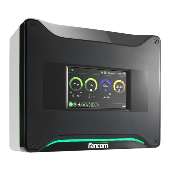
- LUMINA 38
- Instruction manual
-
Contents
-
Table of Contents
-
Bookmarks
Quick Links
Related Manuals for Fancom LUMINA 38
Summary of Contents for Fancom LUMINA 38
-
Page 2
N.B.: The original, authentic version of this manual is the English version produced by Fancom B.V. or one of its daughter companies (referred to further as Fancom). Any modifications introduced to this manual by third parties have neither been checked nor approved by Fancom. Modifications are taken by Fancom to include translations into languages other than English and the insertion and/or deletion of text and/or illustrations to/from the original contents. -
Page 3: Table Of Contents
Table of contents General introduction ……………………..1 Documentation with the control computer………………1 How to use this manual ……………………1 Fancom Sales & Service Center ………………… 2 F-Central FarmManager™ ………………….2 Explanation control functions ……………………3 Ventilation ……………………….3 Heating ……………………….12 Cooling ……………………….
-
Page 4
Lumina 38 Table of contents 10.4 FRM.8 ……………………….59 10.5 Connection FNet and I/O-net ………………….60 Appendix: EC declaration of conformity ………………..61… -
Page 5
Operation and safety instructions These subjects are covered in a separate manual. This manual also applies to other control computers in the Fancom F2000-line. Always read the safety instructions and warnings carefully before using the control computer. Always keep this manual close to the Lumina 38. -
Page 6: Fancom Sales & Service Center
For any questions and support, please contact the local Fancom Sales & Service Center. Virtually all Fancom equipment can be controlled and managed from a central location. This requires the F- Central FarmManager software package and a communication module. The screens in the control computers are…
-
Page 7
Lumina 38 Explanation control functions Please refer to the user’s manual for an explanation of the basic principles of climate management. This chapter describes the working of a number of specific control functions that the installer should set. Ventilation is used to create the most pleasant climate possible in the house. Ventilation also extracts harmful substances from the house and introduces fresh air into the house. -
Page 8
Lumina 38 Explanation control functions The control computer supports four types of house ventilation: • Cross: With side ventilation the house is ventilated on the side. One side is the air inlet, the other side the air outlet. The air flows across the house sideways. The inlet can be a minimum air inlet system or a natural curtain. -
Page 9
Lumina 38 Explanation control functions All controllable fans are always controlled at the same percentage. Figure 3: Example of a controllable fan with one extra controllable fan. Directly controlled by the (A) or by the relay (R) Extra fans can only be switched on or off via a relay. They are usually used when the controllable fans are running at maximum or in combination with controllable fans to achieve a gradual increase in ventilation. -
Page 10: Explanation Control Functions
Lumina 38 Explanation control functions The control computer determines the use of air inlets, extra inlets and fans based on the combi-table. Below is an example of a combi-table. This may differ to your own combi-table, for example, because you use a different number of extra fans.
-
Page 11
Lumina 38 Explanation control functions Example: Taking ventilation positions from the combi-table The required ventilation level on a certain day is 21%. The control computer uses the settings at position M3: • Controllable fans and the extra controllable fans: 25% activated. -
Page 12: Ventilation
Lumina 38 Explanation control functions The settings that have to be made for the tunnel part (T-part) correspond broadly with the settings for the M/MT- part. Instead of the ventilation position in % you enter the offset temperature for the positions. At the first position this offset temperature is linked to start temperature ventilation + calculated bandwidth.
-
Page 13
Modulating control allows minimum ventilation to be achieved using, for example, a large fan. Fancom differentiates between the following types of modulating control: • Modulating control with fixed modulation times •… -
Page 14
Lumina 38 Explanation control functions Linear controlled fans have a minimum ventilation level, for example 30%. This determines below what percentage the ventilation will modulate, and the ventilation level during modulating. If, for example, the calculated output of the linear part is 10%, ventilation will run for 10/30th of the cycle time at 30%, and not run for the rest of the time. -
Page 15
Lumina 38 Explanation control functions In order to ventilate the right amount of air and to have a perfect air distribution, it is possible to ‘pulse’ the air to the middle of the house for a fixed amount of time and then wait until the fresh air is nicely spread over the birds. -
Page 16: Heating
Lumina 38 Explanation control functions The fans which must activate at a certain ventilation position have been set in the relay or combi-table. However, this means that the same fans will always be active. Using rotating the control computer will activate the number of assigned fans, but in a different sequence each time.
-
Page 17
Lumina 38 Explanation control functions The control computer activates heating if the house Setpoint – temperature drops below hysteresis. If the house temperature rises, the heating will stay on until the control value heating is reached. A set Repeat time can be used to prevent unnecessary activation/deactivation of the heating. -
Page 18: Cooling
Lumina 38 Explanation control functions With analog heating control the heating is controlled by a P- or PI-control. Use Repeat time to determine the type of heating control. If the Repeat time is less than 10 seconds, a P-band control is concerned. In other cases PI- control applies.
-
Page 19: Humidifying
Lumina 38 Explanation control functions Time modulating ON/OFF control This type of control can be selected if the cooling capacity is large and the cooling system is suitable for modulating control. Cooling is continually on, if the temperature of the cooling control is higher than Setpoint + hysteresis.
-
Page 20: Humitemp
Lumina 38 Explanation control functions Example: Time modulating humidity control Inside Hysteresis the control computer controls humidity during a part of the Repeat time. The control computer calculates this on/off time as follows: • Setpoint: • Measured RH: • Hysteresis: •…
-
Page 21: Optisec
Lumina 38 Explanation control functions OptiSec = Optimum Setpoint Control The control computer uses a neutral zone, with minimum ventilation and no heating. This lowers energy costs. The neutral zone is the area between control value heating and start temperature ventilation. If OptiSec is not…
-
Page 22
Takes into account the following guidelines: Figure 7: required edge distances Never place the Lumina 38 in a place where the weather has direct influence (not in the sun, not in places where the temperature can rise sharply etc.). Never mount the Lumina 38 near water pipes, drainage pipes etc. -
Page 23
The Lumina 38 should be possible to shut down with a suitable double pole switch which is easily accessible. Connect the Lumina 38 to a group that is fused with 16A from the main distributor and mount the cables in separate cable trays. -
Page 24
Lumina 38 Installing the Lumina 38 The installer can configure the control computer using the installation menu. This menu also contains screens for standard system settings and diagnoses. To call up the installation menu: press the navigation keys UP and DOWN simultaneously for a few seconds. -
Page 25: System
Lumina 38 System SYSTEM → → tab page SYSTEM SYSTEM Common Clock type Setting of the 12 or 24 hour time indication. Time and Date Setting of the current time and date Computer name Setting of the name of the control computer.
-
Page 26
Lumina 38 System → → tab page SYSTEM SYSTEM Units Unit of measurement Setting to simultaneously set all units to METRIC or NON-METRIC. Use the + and – key on the alpha-numeric keyboard to change individual values. → → tab page… -
Page 27: Sd Card Menu
Lumina 38 System → → tab page SYSTEM SYSTEM Sharing Share animal data Setting for sending or receiving animal data. The control computers in the network can share data. In this way the animal data only has to be entered once, at the sender.
-
Page 28: Application
Lumina 38 System Data saved on one control computer can only be loaded into another control computer if both computers are of the same type. In addition, the set control computer numbers must be identical. If both these conditions are not met, loading will fail.
-
Page 29: Communication
Lumina 38 System C is a communication bus used to connect printed circuit boards in the control computer (e.g. AI.4). → → tab page SYSTEM COMMUNICATION Reset counters Setting used to reset all data to zero simultaneously. The IO-Net is a connection for intelligent network modules. For example, Intelligent Relay Modules (IRM), Intelligent Digital Modules (IDM) or Intelligent Sensor Modules (ISM).
-
Page 30
Lumina 38 System FNet is the Fancom Network. Several control computers can be linked via this network. FNet is also used to operate the connected control computers from a PC. → → tab page SYSTEM COMMUNICATION FNet Reset counters Setting used to reset all data to zero simultaneously. -
Page 31: Io Test
Lumina 38 System Use the Input (I) and Output (O) test menu to set the control computer to test the communication channels. In the IO-test menu inputs can be readout and outputs controlled at system level. → SYSTEM IO TEST The functions in the IO-test menu stop all the control actions of the control computer.
-
Page 32: House Setup
Lumina 38 House setup This chapter explains all the options in the HOUSE SETUP menu. HOUSE SETUP select the parts of the control computer you intend to use. The control computer will only display data relevant to you in the screens. Parts not used, will not be shown. Most codes are self explanatory.
-
Page 33
Lumina 38 House setup → tab page HOUSE SETUP Outside Measurement outside Setting indicating if outside temperature measurement is used. If outside temperature temp. measurement is used the outside temperature can influence a number of controls. Measurement outside Setting indicating if outside RH measurement is used. Using absolute moisture calculation, the control computer determines if the outside air is suitable for dehumidification. -
Page 34
Lumina 38 House setup Air inlet in use Setting indicating the number of air inlets to be used. Tunnel inlet in use Setting indicating the number of tunnel inlets to be used. Number of stages M/MT- Setting indicating the number of stages to be used in the combi-table. -
Page 35
Lumina 38 House setup Water clock Setting indicating the number of water clocks to be used. Water registration Setting indicating if water registration is used. Extra clock Setting indicating if extra clocks are used. → tab page HOUSE SETUP User Apply temperature curve Setting indicating if the house temperature is to be controlled based on the curve. -
Page 36
Lumina 38 House setup Night correction Setting indicating if a setpoint correction is required during the dark period (night time) of the day. Linked to Setting indicating which light clock is used to determine the dark period times. → tab page →… -
Page 37
Lumina 38 House setup → tab page HOUSE SETUP OptiSec Band Setting of the maximum correction (Band). The control computer can increase the setpoint heating until this equals the setpoint house temperature. Delay Setting of the Delay to minimise the influence of temperature fluctuations. -
Page 38: Installer
Lumina 38 Installer This chapter explains all the options in the INSTALLER menu. In the combi-table the relationship between ventilation and air inlets for the entire ventilation course is entered. For more information about the combi-table, see “Combi-table page 5”.
-
Page 39
Lumina 38 Installer Con. The entry depends on the system setting M/MT-part HOUSE SETUP, tab page Con. Extra Mod. % Combi: • Con. Enter the positions of the linear controllable fans. • Con. Extra (This column is only active if extra fans are used in the controllable part) -
Page 40
Lumina 38 Installer → → → → tab page INSTALLER VENTILATION COMBI MTT M/MT-phase(min) Cap. Position % Setting of the ventilation percentage at which fans should activate/deactivate and air inlets open/close. The ventilation percentages must increase from the lowest to the highest position. -
Page 41
Lumina 38 Installer → → → tab page INSTALLER VENTILATION SETTINGS Miscell. When using T-inlets, the house sizes are required to be able to calculate the airspeed during T-phase. House length Setting of the length of the house. House width Setting of the width of the house. -
Page 42
Lumina 38 Installer → → → tab page INSTALLER VENTILATION SETTINGS M/MT-Part Description Setting of the name of the function. Output address Setting of the analog output address. Analog type Setting indicating the analog control type Extra analog Setting of the analog output address. -
Page 43
Lumina 38 Installer Modulating: FIXED TIME Modulate under % Setting of the ventilation percentage, below which the control computer will apply modulating control to the linearly controlled part. This applies to fans that cannot be controlled below this percentage. Linearly controllable fans usually have a minimum ventilation level. -
Page 44
Lumina 38 Installer → → → tab page INSTALLER VENTILATION SETTINGS Relay Rotation time Setting of the period after which the relays rotate. Output address Setting of the combi relay addresses. Rotate Setting indicating if fans, controlled by the combi-relays, rotate in a certain sequence. -
Page 45: Ventilation
Lumina 38 Installer → → → tab page INSTALLER VENTILATION INLETS Inlet Description Setting of the name of the function. Temp. inputs Setting the addresses of the analog inputs. If the temperature sensors have not been assigned, the control computer will use the house temperature.
-
Page 46
Lumina 38 Installer Output address Setting of the analog output address. Analog type Setting indicating the analog control type Pre-run time Setting of the time in which the air inlets go to the required position, before the fans activate. Setting indicating if these air inlets are to be included in modulating ventilation — if Modulate link modulating ventilation is used. -
Page 47
Lumina 38 Installer → INSTALLER COOLING Description Setting of the name of the function. Temp. inputs Setting the addresses of the analog inputs. If the temperature sensors have not been assigned, the control computer will use the house temperature. Control… -
Page 48
Lumina 38 Installer In the clocks and registration menu enter the settings for the clocks used per house. In the menu HOUSE SETUP the clocks to be used have already been entered. The data for these clocks can be set here. -
Page 49
Lumina 38 Installer The water clock controls the water supply in the house. 11 clocks can be used per house (1 central clock and 10 clocks for each water line). You only need to set the central clock settings (Reg-02). The settings for each water line will be assigned automatically. -
Page 50
Lumina 38 Installer Description Setting of the name of the function. Time clock type Setting indicating how the user can use the clock: • ON/OFF: User enters on/off times. • ON/DURATION: User enters time and duration of activation. Time clock relay… -
Page 51: Registration
Lumina 38 Installer Control on Setting of the way in which light is controlled. This option is only available if light measurement=YES has been selected at light clocks. • LUX: If you want to control the light using a light sensor, select LUX. The light clock will adjust the light intensity to the measured light intensity.
-
Page 52: Inside Climate
Lumina 38 Installer Reg. Input Setting the type of measurement: • MANUALLY: Enables you to enter the amount of today manually. • SLOW PULSE: Measuring instruments with a maximum frequency of 20 pulses per second (20 Hz). • QUICK PULSE: Measuring instruments with a maximum frequency of 20 pulses per second (20 Hz) (only use when there is a link with a switch clock).
-
Page 53
Lumina 38 Installer Speed press. contr. Setting of the speed at which the control computer determines influences (SLOW MODERATE / FAST). Input <x> measurement Setting the address of the analog input. where x is RH, NH3 or Speed <x> control… -
Page 54
Lumina 38 Installer Type wind measure Setting of the type of anemometer used. Fancom uses the following types of weather meters: • GREEN_2P (default) • BLACK_4P • BLACK_2P • DAVIS • By choosing the required type and assigning the correct inputs, the control computer will automatically make all corresponding settings. -
Page 55: External Alarm
Lumina 38 External alarm The control computer can connect to external alarm contacts and respond appropriately. EXTERN.ALARM Description Setting of the name of the function. Input address Setting of the address of the digital input. The readout of the input value is between brackets.
-
Page 56: Basic Principle Thermo Differential
Lumina 38 Basic principle thermo differential An extreme rise in house temperature can be caused by fire. In such a case, it is important that an alarm is raised quickly. The sensors (assigned to the house temperature) in the zones can detect sudden rises in temperature. A sensor issues an alarm if: •…
-
Page 57
Lumina 38 Basic principle thermo differential Relais type Setting of the passive (not controlled) relay status. • N.O. (normally open) if it makes no contact. • N.C. (normally closed) if it makes contact. Alarm type Setting for the way in which the alarm will be processed. -
Page 58: Inputs And Outputs
Lumina 38 Inputs and outputs When controls are assigned, the I/O settings are filled in automatically. When Fancom equipment is used these settings will normally ensure correct control. These settings can be adjusted using the zoom function ( The input and output settings can be readout, and changed in the INPUT / OUTPUT menu. However, we advise you not to make changes here but to do these changes in the setup screens.
-
Page 59
Lumina 38 Inputs and outputs Type Setting of the type of measurement being carried out: • NONE • TEMPERATURE • CO2 3000 PP • CO2 30000 PP • LINEAR (U) • LINEAR (R) • POLYNOMIAL (U) • LUX (R) Measurement The measured signal (if changed manually, the correction value is adjusted accordingly). -
Page 60
Lumina 38 Inputs and outputs Min.jump…max The control range of the analog output. Enter the minimum and maximum jump (in %). Actual value Shows the actual value of the control voltage of the analog output. Digital outputs have the following settings: Output address The address of the output. -
Page 61: Digital Inputs
Relay: make-and-break contact, voltage free Max. 2A 60Vdc/30Vac Communication I/O-Net for extra inputs and outputs using I/O-modules. FNet, Fancom network for intercommunication of control computers and PC connection. FRM.8 8 Digital outputs (relays) Relay 1, 3, 5, 7: make-and-break contact Max.
-
Page 62
Lumina 38 Technical specifications Touch screen HI mainboard LED strip FUNC (CPU) IOB.12 (I/O) Power supply Internal relays (2x FRM.8) -
Page 63
Lumina 38 Technical specifications AI type Type analog input • Voltage measurement (U: • Resistance measurement (R: 6 Analog outputs 12 Analog inputs 8 Digital inputs 2×8 digital outputs… -
Page 64
The control computer and the second I/O network module require a terminal resistor. The first I/O network module is looped. This does not require a terminal resistor. The Fancom Greenlink cable (UTP 1x2x0.8mm, unshielded twisted pair) used to wire the FNET and I/O net. Maximum cable length = 1200 meters. -
Page 65
Lumina 38 Appendix: EC declaration of conformity Manufacturer Fancom B.V. Address: Industrieterrein 34 Place: Panningen (the Netherlands) Hereby declares that: Lumina 38 Satisfies the conditions of: The Low Voltage Directive 2014/35/EU according to EN-61010 the EMC Guideline, directive 2014/30/EU Emission and immunity according to NEN-EN-IEC 61326…
Компьютер Lumina 38 / F38 (старая версия) Fancom
Автоматическая регулировка параметров приточного и отработанного воздуха и системы отопления с помощью компьютера Lumina 38.
Мощность системы микроклимата индивидуально подбирается и конфигурируется в зависимости от требований. Множество локальных датчиков создают во всем корпусе не только комфортный и равномерный микроклимат, стимулирующий рост животных, но и дают возможность делить корпус на разные климатические зоны
Lumina 38 может использоваться в птичниках следующих типов:
- Птичники для несушек
- Птичники для молодняка
- Птичники для молодняка кур-несушек
- Бройлерники
- Индюшатники
Lumina 38 отлично подходит для регулирования климата в MTT-помещении. Аббревиатура MTT означает Минимальная / Промежуточная / Туннельная. Используя данную концепцию, компьютер постепенно увеличивает вентиляцию с минимальной до туннельной вентиляции. Использование туннельной вентиляции при теплом климате, таком как на Ближнем Востоке или в Азии. Однако туннельная вентиляция может также использоваться при умеренном или холодном климате для предупреждения падежа во время жаркой погоды. Благодаря МТТ-концепции компании Fancom переход от минимальной к туннельной вентиляции осуществляется постепенно. Дополнительные затраты на туннельную вентиляцию (в сравнении с другими системами) незначительны благодаря эффективному использованию оборудования.


Технические характеристики компьютер Lumina 38 / F38

Запчасти к LUMINA 38 TOUCH / F38 FANCOM — компьютер управления микроклиматом:
| Артикул | Наименование | |
 |
A1471009.05 | HI BASIC A2 PROGRAMMED |
 |
A1471022 | LED BOARD 360 |
 |
A1471032 | HI+ BOARD A2 |
 |
A1541022.05 | DISPLAY 240X320 LED W. TESTED |
 |
A1541032.05 | DISPL.COLOR 7 + CARRIER |
 |
A1755039 | IOB.12 BOARD B1.1 |
| A1755051.05 | SBC LUMINA AM3354-1000C+PROGR. | |
| A1755051.07 | SBC LUM.AM3354-1000C+PR.L.LNX | |
| A2431070 | PS 24V+5VDC 50W + CARRIER | |
| A3470066.05 | FRM.8 BOARD A0 TESTED | |
| A3470073 | K360 BOARD A1.0-2 9.5MM BUTTON | |
| A3470128 | DISPLAY 240X320 LED WHITE + HI | |
| A3739022 | FLAT CABLE + CON. 20P 70MM | |
| A3739023 | FLAT CABLE + CON. 20P 200MM | |
| A3739024 | FLAT CABLE + CON. 10P 260MM | |
| A3739026 | FLAT CABLE + CON. 10P 150MM | |
| A3799025 | COVER WITH GLASS 360 | |
| A3851015 | CABLE TREE P. SUPP F2000 550MM | |
| A3851016 | CABLE TREE POWER SUPPLY | |
| A5105085 | FUNC BOARD UNPROTECTED + F2KU | |
| A7859025 | COVER 360 LUMINA TOUCH | |
| A7859025.02 | COVER 360 LUMINA TOUCH LNX |
Specifications:
|
Accompanying Data:
Fancom LUMINA 38 Control Systems PDF Instruction Manual (Updated: Thursday 26th of January 2023 07:37:58 AM)
Rating: 4.6 (rated by 11 users)
Compatible devices: HARmonica, IMS, MRK.2, 750, LUMINA 41, FB.1, PR611-VP, ATC TRAILER CONTROL.
Recommended Documentation:
Fancom LUMINA 38: Text of Instruction Manual
(Ocr-Read Version Summary of Contents, UPD: 26 January 2023)
-
60, Lumina 38 Inputs and outputs 56 Min.jump…max The control range of the analog output. Enter the minimum and maximum jump (in %). Actual value Shows the actual value of the control voltage of the analog output. Digital outputs have the following settings: Output address The address of the output. Channel type Shows the type of relay…
-
20, Lumina 38 Explanation control functions 16 Example: Time modulating humidity control Inside Hysteresis the control computer controls humidity during a part of the Repeat time. The control computer calculates this on/off time as follows: • Setpoint: 80% • Measured RH: 75% • Hysteresis: 10% • Repeat time: 100 …
-
57, Lumina 38 Basic principle thermo differential 53 Relais type Setting of the passive (not controlled) relay status. • N.O. (normally open) if it makes no contact. • N.C. (normally closed) if it makes contact. Alarm type Setting for the way in which the alarm will be processed. • LOUD: Loud alarm (switch the alarm relay). • SILENT: Silent alarm. …
-
49, Lumina 38 Installer 45 The water clock controls the water supply in the house. 11 clocks can be used per house (1 central clock and 10 clocks for each water line). You only need to set the central clock settings (Reg-02). The settings for each water line will be assigned automatically. Use registration input 11 till 20 for each water line. INST…
-
17, Lumina 38 Explanation control functions 13 The control computer activates heating if the house temperature drops below Setpoint – hysteresis. If the house temperature rises, the heating will stay on until the control value heating is reached. A set Repeat time can be used to prevent unnecessary activation/deactivation of the heating. When the heating activates, …
-
35, Lumina 38 House setup 31 Water clock Setting indicating the number of water clocks to be used. Water registration Setting indicating if water registration is used. Extra clock Setting indicating if extra clocks are used. HOUSE SETUP → tab page User Apply temperature curve Setting indicating if the house temperature is to be controlled based on…
-
31, Lumina 38 System 27 Use the Input (I) and Output (O) test menu to set the control computer to test the communication channels. In the IO-test menu inputs can be readout and outputs controlled at system level. SYSTEM → IO TEST The functions in the IO-test menu stop all the control actions of the control computer. Only …
-
13, Lumina 38 Explanation control functions 9 Ventilation Exhaust Inlets Position MOD Extra fans Relay (0-1-M) Cap. Inlet Extra Pres- sure % % 1 2 3 4 5 m3/h % % Pa M1 1 1 M 0 0 0 0 200 1 0 0 M2 20 100 M 0 0 0 0 20000 20 0 0 M3 21 50 M M 0 0 …
-
61, Lumina 38 Technical specifications 57 Power supply Mains voltage 100 – 240Vac Mains frequency 50/60Hz Maximum power consumption 50VA IOB.12 Power available for sensors 24Vdc, fused Max. 200mA 12Vdc, short circuit resistant Max. 70mA Power available for sensors and peripheral equipment 24Vdc, short circuit resistant Max. 500mA 6�…
-
8, Lumina 38 Explanation control functions 4 The control computer supports four types of house ventilation: • Cross: With side ventilation the house is ventilated on the side. One side is the air inlet, the other side the air outlet. The air flows across the house sideways. The inlet can be a minimum air inlet system or a natural curtain. The outlet is mechanical (fan). …
-
39, Lumina 38 Installer 35 Con. / Con. Extra / Mod. % The entry depends on the system setting M/MT-part in HOUSE SETUP, tab page Combi: • Con. Enter the positions of the linear controllable fans. • Con. Extra (This column is only active if extra fans are used in the controllable part) Control of extra fan Settings: Position 0-R f…
-
22, Lumina 38 Installing the Lumina 38 18 Takes into account the following guidelines: Figure 7: required edge distances Never place the Lumina 38 in a place where the weather has direct influence (not in the sun, not in places where the temperature can rise sharply etc.). Never mount the Lumina 38 near water pipes, drainage pipes etc…
-
4, Lumina 38 Table of contents ii 10.4 FRM.8 …………………………………………………………………………………………………………………………. 59 10.5 Connection FNet and I/O-net ………………………………………………………………………………………….. 60 11. Appendix: EC…
-
65, Lumina 38 Appendix: EC declaration of conformity 61 Manufacturer Fancom B.V. Address: Industrieterrein 34 Place: Panningen (the Netherlands) Hereby declares that: Lumina 38 Satisfies the conditions of: 1. The Low Voltage Directive 2014/35/EU according to EN-61010 2. the EMC Guideline, directive 2014/30/EU Emission and immunity according to NEN-EN-IEC …
Fancom LUMINA 38: Recommended Instructions
KX-HGT100EX, FRONT-LOADINGAUTOMATIC WASHER, SRT 6011, PSO301M, iKaraoke


-
Valid forSoftware VersionSINUMERIK 840D/DE powerline 7.4SINUMERIK 840Di/DiE powerline 3.3SINUMERIK 810D/DE powerline 7.4SINUMERIK 840D sl/DE sl 1.4SINUMERIK 840Di sl/DiE sl 1.4SINUMERIK 802D sl 1.404.2007 EditionProgramming Manual ISO MillingSINUMERIK 802D sl/840D/840D sl/840Di//840Di sl/810DProgramming GuideProgramming GuideProgramming GuideProgramming GuideProgramming GuideProgramming GuidePro …
SINUMERIK 802D sl 251
-
SINUMERIKSINUMERIK MCMCU commissioning: NC, PLC, DriveCommissioning ManualValid for:SINUMERIK MCCNC software V1.13SINUMERIK TIA Portal V16SINUMERIK MC STEP 7 Toolbox V16SINAMICS drives S120/S21002/2020A5E47437618B ABPrefaceFundamental safety instructions1Introduction2Requirements for commissioning3Licensing4PLC commissioning5Commissioning NC-controlled …
SINUMERIK MC 288
-
KTP400 BasicKTP700 BasicKTP900 BasicKTP1200 BasicKTP400 BasicKTP700 BasicKTP900 BasicKTP1200 BasicML+6 mmhttp://support.automation.siemens.com/WW/view/en/80856506/133300Dieses Dokument ist lediglich eine Montageanleitung. Sicherheitshinweise, sowie die vollständige Montage und Inbetriebnahme sind in der Betriebsanleitung beschrieben.This document provides simple installation instru …
SIMATIC HMI KTP400 Basic 2
-
SLAM SPECIALTIESControl SystemsModel No. : MC.1-SSMade in USAThank you for purchasing the MC.1 Controller from Slam Specialties. This page includes installation instruc-tions as well as contact information for technical support. If you have any questions about the operation of this unit, please call 888-352-5225.The MC.1 is a two part control system for air suspension vehicles cons …
MC.1-SS 3
-
Tigo Rapid ShutdownDO NOTDISCONNECTUNDER LOADDANGERNEC690.12-2017and C22.1-2015Rule 64.218For installation with frameless modules,remove metal clips and bolt TS4-A to rail.Removable clipsMounting holes (M8)Note: When installing TS4-A or TS4-A-Duo, connect the input cables to the PV modulebefore connecting the TS4-A output cables in series.If disconnecting TS4-A or TS4-A-Duo, disco …
TS4-A-O 2
-
Refer to the QuickLIT website for the most up-to-date version of this document.1System 450™ Series Modular Control Systems with Standard Control Modules Technical BulletinDocument Introduction. . . . . . . . . . . . . . . . . . . . . . . . . . . . . . . . . . . . . . . . . . . . . . . . . 3System 450 Overview . . . . . . . . . . . . . . . . . . . . . . . . . …
System 450 Series 78
-
50M56U-801Single Stage | Direct | HSIIntegrated Furnace Control KitINSTALLATION INSTRUCTIONSFAILURE TO READ AND FOLLOW ALL INSTRUCTIONS CAREFULLY BEFORE INSTALLING OR OPERATING THIS CONTROL COULD CAUSE PERSONAL INJURY AND/OR PROPERTY DAMAGE.Description ……………………………………………………………………………………………………………………………….. …
50M56U-801 16
-
Americas HeadquartersCisco Systems, Inc.170 West Tasman DriveSan Jose, CA 95134-1706 USAhttp://www.cisco.comTel: 408 526-4000800 553-NETS (6387)Fax: 408 527-0883Cisco SCE8000 Software Configuration GuideRelease 3.1.6S February 15, 2011Text Part Number: OL-16479-01 …
SCE8000 262
Additional Information:
Popular Right Now:
Operating Impressions, Questions and Answers:
Компьютер управления микроклиматом Lumina 38 Touch / F38 Fancom
Климатический компьютер Lumina 38 (Fancom) — это климатический компьютер для птичников. Климатический компьютер является универсальным и подходит для использования в широком спектре климатических условий.
Регулировка параметров приточного и отработанного воздуха и системы отопления с помощью компьютера Lumina 38 (Fancom) осуществляется полностью автоматически. При сбое системы подается аудиовизуальный сигнал аварийной сигнализации.
Мощность системы микроклимата индивидуально подбирается и конфигурируется в зависимости от требований. Множество локальных датчиков создают во всем корпусе не только комфортный и равномерный микроклимат, стимулирующий рост животных, но и дают возможность делить корпус на разные климатические зоны
Lumina 38 может использоваться по всему миру в птичниках следующих типов:
- Птичники для несушек
- Птичники для молодняка
- Птичники для молодняка кур-несушек
- Птичники для бройлеров
- Птичники для индеек
Характеристики раздаточного компьютера:
- Полностью компьютеризированная система климат-контроля в соответствии с жизненным циклом животных.
- Управление животными: Регистрация количества животных, их доставки и падежа.
- Управление внешним оборудованием с помощью таймеров. Регистрация расхода (например, газа или электричества) на основании полученной информации.
Lumina 38 отлично подходит для регулирования климата в MTT-помещении. Аббревиатура MTT означает Минимальная/Промежуточная/Туннельная. Используя данную концепцию, раздаточный компьютер постепенно увеличивает вентиляцию с минимальной до туннельной вентиляции. Использование туннельной вентиляции (практически) очевидно при теплом климате, таком как на Ближнем Востоке или в Азии. Однако туннельная вентиляция может также использоваться при умеренном или холодном климате для предупреждения падежа во время жаркой погоды. Благодаря МТТ-концепции компании Fancom переход от минимальной к туннельной вентиляции осуществляется постепенно. Дополнительные затраты на туннельную вентиляцию (в сравнении с другими системами) незначительны благодаря эффективному использованию оборудования.
Компания «ЦентрАгро» готова предложить Вашему вниманию большую номенклатуру комплектующих и запасных частей для любого вида импортного, а также отечественного оборудования в рамках модернизации и переоснащения старого фонда, а также внеплановой комплектации запчастями различных участков предприятия – от инкубации до убоя и переработки птицы.