flat assembler
Documentation and tutorials.
flat assembler 1.73
Programmer’s Manual
Table of Contents
Chapter 1 — Introduction
1.1 Compiler overview
1.1.1 System requirements
1.1.2 Executing compiler from command line
1.1.3 Compiler messages
1.1.4 Output formats
1.2 Assembly syntax
1.2.1 Instruction syntax
1.2.2 Data definitions
1.2.3 Constants and labels
1.2.4 Numerical expressions
1.2.5 Jumps and calls
1.2.6 Size settings
Chapter 2 — Instruction Set
2.1 The x86 architecture instructions
2.1.1 Data movement instructions
2.1.2 Type conversion instructions
2.1.3 Binary arithmetic instructions
2.1.4 Decimal arithmetic instructions
2.1.5 Logical instructions
2.1.6 Control transfer instructions
2.1.7 I/O instructions
2.1.8 Strings operations
2.1.9 Flag control instructions
2.1.10 Conditional operations
2.1.11 Miscellaneous instructions
2.1.12 System instructions
2.1.13 FPU instructions
2.1.14 MMX instructions
2.1.15 SSE instructions
2.1.16 SSE2 instructions
2.1.17 SSE3 instructions
2.1.18 AMD 3DNow! instructions
2.1.19 The x86-64 long mode instructions
2.1.20 SSE4 instructions
2.1.21 AVX instructions
2.1.22 AVX2 instructions
2.1.23 Auxiliary sets of computational instructions
2.1.24 AVX-512 instructions
2.1.25 Other extensions of instruction set
2.2 Control directives
2.2.1 Numerical constants
2.2.2 Conditional assembly
2.2.3 Repeating blocks of instructions
2.2.4 Addressing spaces
2.2.5 Other directives
2.2.6 Multiple passes
2.3 Preprocessor directives
2.3.1 Including source files
2.3.2 Symbolic constants
2.3.3 Macroinstructions
2.3.4 Structures
2.3.5 Repeating macroinstructions
2.3.6 Conditional preprocessing
2.3.7 Order of processing
2.4 Formatter directives
2.4.1 MZ executable
2.4.2 Portable Executable
2.4.3 Common Object File Format
2.4.4 Executable and Linkable Format
Chapter 1
Introduction
This chapter contains all the most important information you need to begin
using the flat assembler. If you are experienced assembly language programmer,
you should read at least this chapter before using this compiler.
1.1 Compiler overview
Flat assembler is a fast assembly language compiler for the x86 architecture
processors, which does multiple passes to optimize the size of generated
machine code. It is self-compilable and versions for different operating
systems are provided. All the versions are designed to be used from the system
command line and they should not differ in behavior.
1.1.1 System requirements
All versions require the x86 architecture 32-bit processor (at least 80386),
although they can produce programs for the x86 architecture 16-bit processors,
too. DOS version requires an OS compatible with MS DOS 2.0 and either true
real mode environment or DPMI. Windows version requires a Win32 console
compatible with 3.1 version.
1.1.2 Executing compiler from command line
To execute flat assembler from the command line you need to provide two
parameters — first should be name of source file, second should be name of
destination file. If no second parameter is given, the name for output
file will be guessed automatically. After displaying short information about the program name
and version, compiler will read the data from source file and compile it.
When the compilation is successful, compiler will write the generated code
to the destination file and display the summary of compilation process;
otherwise it will display the information about error that occurred.
In the command line you can also include -m option followed by a number,
which specifies how many kilobytes of memory flat assembler should maximally
use. In case of DOS version this options limits only the usage of extended
memory. The -p option followed by a number can be used to specify the limit
for number of passes the assembler performs. If code cannot be generated
within specified amount of passes, the assembly will be terminated with an
error message. The maximum value of this setting is 65536, while the default
limit, used when no such option is included in command line, is 100.
The source file should be a text file, and can be created in any text
editor. Line breaks are accepted in both DOS and Unix standards, tabulators
are treated as spaces.
There are no command line options that would affect the output of compiler,
flat assembler requires only the source code to include the information it
really needs. For example, to specify output format you specify it by using the
format directive at the beginning of source.
1.1.3 Compiler messages
As it is stated above, after the successful compilation, the compiler displays
the compilation summary. It includes the information of how many passes was
done, how much time it took, and how many bytes were written into the
destination file.
The following is an example of the compilation summary:
flat assembler  version 1.73 (16384 kilobytes memory)
38 passes, 5.3 seconds, 77824 bytes.
In case of error during the compilation process, the program will display an
error message. For example, when compiler can’t find the input file, it will
display the following message:
flat assembler  version 1.73 (16384 kilobytes memory)
error: source file not found.
If the error is connected with a specific part of source code, the source line
that caused the error will be also displayed. Also placement of this line in
the source is given to help you finding this error, for example:
flat assembler  version 1.73 (16384 kilobytes memory)
example.asm [3]:
        mob     ax,1
error: illegal instruction.
It means that in the third line of the example.asm file compiler has
encountered an unrecognized instruction. When the line that caused error
contains a macroinstruction, also the line in macroinstruction definition
that generated the erroneous instruction is displayed:
flat assembler  version 1.73 (16384 kilobytes memory)
example.asm [6]:
        stoschar 7
example.asm [3] stoschar [1]:
        mob     al,char
error: illegal instruction.
It means that the macroinstruction in the sixth line of the example.asm file
generated an unrecognized instruction with the first line of its definition.
1.1.4 Output formats
By default, when there is no format directive in source file, flat
assembler simply puts generated instruction codes into output, creating this
way flat binary file. By default it generates 16-bit code, but you can always
turn it into the 16-bit or 32-bit mode by using use16 or use32 directive.
Some of the output formats switch into 32-bit mode, when selected — more
information about formats which you can choose can be found in 2.4.
All output code is always in the order in which it was entered into the
source file.
1.2 Assembly syntax
The information provided below is intended mainly for the assembly language
programmers that have been using some other assembly compilers before.
If you are beginner, you should look for the assembly programming tutorials.
Flat assembler by default uses the Intel syntax for the assembly
instructions, although you can customize it using the preprocessor
capabilities (macroinstructions and symbolic constants). It also has its own
set of the directives — the instructions for compiler.
All symbols defined inside the sources are case-sensitive.
1.2.1 Instruction syntax
Instructions in assembly language are separated by line breaks, and one
instruction is expected to fill the one line of text. If a line contains
a semicolon, except for the semicolons inside the quoted strings, the rest of
this line is the comment and compiler ignores it. If a line ends with
character (eventually the semicolon and comment may follow it), the next line
is attached at this point.
Each line in source is the sequence of items, which may be one of the three
types. One type are the symbol characters, which are the special characters
that are individual items even when are not spaced from the other ones.
Any of the +-/*=<>()[]{}:,|&~#` is the symbol character. The sequence of
other characters, separated from other items with either blank spaces or
symbol characters, is a symbol. If the first character of symbol is either a
single or double quote, it integrates any sequence of characters following
it, even the special ones, into a quoted string, which should end with the same
character, with which it began (the single or double quote) — however if there
are two such characters in a row (without any other character between them),
they are integrated into quoted string as just one of them and the quoted
string continues then. The symbols other than symbol characters and quoted
strings can be used as names, so are also called the name symbols.
Every instruction consists of the mnemonic and the various number of
operands, separated with commas. The operand can be register, immediate value
or a data addressed in memory, it can also be preceded by size operator to
define or override its size (table 1.1). Names of available registers you can
find in table 1.2, their sizes cannot be overridden. Immediate value can be
specified by any numerical expression.
When operand is a data in memory, the address of that data (also any
numerical expression, but it may contain registers) should be enclosed in
square brackets or preceded by ptr operator. For example instruction
mov eax,3 will put the immediate value 3 into the EAX register, instruction
mov eax,[7] will put the 32-bit value from the address 7 into EAX and the
instruction mov byte [7],3 will put the immediate value 3 into the byte at
address 7, it can also be written as mov byte ptr 7,3.
To specify which segment register should be used for addressing, segment register name followed
by a colon should be put just before the address value (inside the square
brackets or after the ptr operator).
Table 1.1 Size operators
| Operator | Bits | Bytes |
|---|---|---|
byte |
8 | 1 |
word |
16 | 2 |
dword |
32 | 4 |
fword |
48 | 6 |
pword |
48 | 6 |
qword |
64 | 8 |
tbyte |
80 | 10 |
tword |
80 | 10 |
dqword |
128 | 16 |
xword |
128 | 16 |
qqword |
256 | 32 |
yword |
256 | 32 |
dqqword |
512 | 64 |
zword |
512 | 64 |
Table 1.2 Registers
| Type | Bits | |||||||||
|---|---|---|---|---|---|---|---|---|---|---|
| General | 8 |
|
||||||||
| 16 |
|
|||||||||
| 32 |
|
|||||||||
| Segment | 16 |
|
||||||||
| Control | 32 |
|
||||||||
| Debug | 32 |
|
||||||||
| FPU | 80 |
|
||||||||
| MMX | 64 |
|
||||||||
| SSE | 128 |
|
||||||||
| AVX | 256 |
|
||||||||
| AVX-512 | 512 |
|
||||||||
| Opmask | 64 |
|
||||||||
| Bounds | 128 |
|
1.2.2 Data definitions
To define data or reserve a space for it, use one of the directives listed in
table 1.3. The data definition directive should be followed by one or more of
numerical expressions, separated with commas. These expressions define the
values for data cells of size depending on which directive is used. For
example db 1,2,3 will define the three bytes of values 1, 2 and 3
respectively.
The db and du directives also accept the quoted string values of any
length, which will be converted into chain of bytes when db is used and into
chain of words with zeroed high byte when du is used.
For example db 'abc' will define the three bytes of values 61, 62 and 63.
The dp directive and its synonym df accept the values consisting of two
numerical expressions separated with colon, the first value will become the
high word and the second value will become the low double word of the far
pointer value. Also dd accepts such pointers consisting of two word values
separated with colon, and dt accepts the word and quad word value separated
with colon, the quad word is stored first. The dt directive with single
expression as parameter accepts only floating point values and creates data in
FPU double extended precision format.
Any of the above directive allows the usage of special dup operator to
make multiple copies of given values. The count of duplicates should precede
this operator and the value to duplicate should follow — it can even be the
chain of values separated with commas, but such set of values needs to be
enclosed with parenthesis, like db 5 dup (1,2), which defines five copies
of the given two byte sequence.
The file is a special directive and its syntax is different. This
directive includes a chain of bytes from file and it should be followed by the
quoted file name, then optionally numerical expression specifying offset in
file preceded by the colon, then — also optionally — comma and numerical
expression specifying count of bytes to include (if no count is specified, all
data up to the end of file is included). For example file 'data.bin' will
include the whole file as binary data and file 'data.bin':10h,4 will include
only four bytes starting at offset 10h.
The data reservation directive should be followed by only one numerical
expression, and this value defines how many cells of the specified size should
be reserved. All data definition directives also accept the ? value, which
means that this cell should not be initialized to any value and the effect is
the same as by using the data reservation directive. The uninitialized data
may not be included in the output file, so its values should be always
considered unknown.
Table 1.3 Data directives
| Size (bytes) | Define data | Reserve data | ||||
|---|---|---|---|---|---|---|
| 1 |
|
rb |
||||
| 2 |
|
rw |
||||
| 4 | dd |
rd |
||||
| 6 |
|
|
||||
| 8 | dq |
rq |
||||
| 10 | dt |
rt |
1.2.3 Constants and labels
In the numerical expressions you can also use constants or labels instead of
numbers. To define the constant or label you should use the specific
directives. Each label can be defined only once and it is accessible from the
any place of source (even before it was defined). Constant can be redefined
many times, but in this case it is accessible only after it was defined, and
is always equal to the value from last definition before the place where it’s
used. When a constant is defined only once in source, it is — like the label —
accessible from anywhere.
The definition of constant consists of name of the constant followed by the
= character and numerical expression, which after calculation will become
the value of constant. This value is always calculated at the time the
constant is defined. For example you can define count constant by using the
directive count = 17 and then use it in the assembly instructions, like
mov cx,count — which will become mov cx,17 during the compilation process.
There are different ways to define labels. The simplest is to follow the
name of label by the colon, this directive can even be followed by the other
instruction in the same line. It defines the label whose value is equal to
offset of the point where it’s defined. This method is usually used to label
the places in code. The other way is to follow the name of label (without a
colon) by some data directive. It defines the label with value equal to
offset of the beginning of defined data, and remembered as a label for data
with cell size as specified for that data directive in table 1.3.
The label can be treated as constant of value equal to offset of labeled
code or data. For example when you define data using the labeled directive
char db 224, to put the offset of this data into BX register you should use
mov bx,char instruction, and to put the value of byte addressed by char
label to DL register, you should use mov dl,[char] (or mov dl,ptr char).
But when you try to assemble mov ax,[char], it will cause an error, because
fasm compares the sizes of operands, which should be equal. You can force
assembling that instruction by using size override: mov ax,word [char],
but remember that this instruction will read the two bytes beginning at char
address, while it was defined as a one byte.
The last and the most flexible way to define labels is to use label
directive. This directive should be followed by the name of label, then
optionally size operator (it can be preceded by a colon) and then — also
optionally at operator and the numerical expression defining the address at
which this label should be defined. For example label wchar word at char
will define a new label for the 16-bit data at the address of char. Now the
instruction mov ax,[wchar] will be after compilation the same as
mov ax,word [char]. If no address is specified, label directive defines
the label at current offset. Thus mov [wchar],57568 will copy two bytes
while mov [char],224 will copy one byte to the same address.
The label whose name begins with dot is treated as local label, and its name
is attached to the name of last global label (with name beginning with
anything but dot) to make the full name of this label. So you can use the
short name (beginning with dot) of this label anywhere before the next global
label is defined, and in the other places you have to use the full name. Label
beginning with two dots are the exception — they are like global, but they
don’t become the new prefix for local labels.
The @@ name means anonymous label, you can have defined many of them in
the source. Symbol @b (or equivalent @r) references the nearest preceding
anonymous label, symbol @f references the nearest following anonymous label.
These special symbol are case-insensitive.
1.2.4 Numerical expressions
In the above examples all the numerical expressions were the simple numbers,
constants or labels. But they can be more complex, by using the arithmetical
or logical operators for calculations at compile time. All these operators
with their priority values are listed in table 1.4.
The operations with higher priority value will be calculated first, you can
of course change this behavior by putting some parts of expression into
parenthesis. The +, -, * and / are standard arithmetical operations,
mod calculates the remainder from division. The and, or, xor, shl,
shr, bsf, bsr and not perform the same bit-logical operations as assembly instructions
of those names.
The rva and plt are special unary operators that perform conversions
between different kinds of addresses, they can be used only with few of the
output formats and their meaning may vary (see 2.4).
The artithmetical and bit-logical calculations are usually processed as if they
operated on infinite precision 2-adic numbers, and assembler signalizes an
overflow error if because of its limitations it is not table to perform the
required calculation, or if the result is too large number to fit in either
signed or unsigned range for the destination unit size.
The numbers in the expression are by default treated as a decimal, binary
numbers should have the b letter attached at the end, octal number should
end with o letter, hexadecimal numbers should begin with 0x characters
(like in C language) or with the $ character (like in Pascal language) or
they should end with h letter. Also quoted string, when encountered in
expression, will be converted into number — the first character will become
the least significant byte of number.
The numerical expression used as an address value can also contain any of
general registers used for addressing, they can be added and multiplied by
appropriate values, as it is allowed for the x86 architecture instructions.
The numerical calculations inside address definition by default operate with
target size assumed to be the same as the current bitness of code, even if
generated instruction encoding will use a different size.
There are also some special symbols that can be used inside the numerical
expression. First is $, which is always equal to the value of current
offset, while $$ is equal to base address of current addressing space.
The other one is %, which is the number of current repeat in parts of code
that are repeated using some special directives (see 2.2) and zero anywhere else.
There’s also %t symbol, which is always equal to the current time stamp.
Any numerical expression can also consist of single floating point value
(flat assembler does not allow any floating point operations at compilation
time) in the scientific notation, they can end with the f letter to be
recognized, otherwise they should contain at least one of the . or E
characters. So 1.0, 1E0 and 1f define the same floating point value,
while simple 1 defines an integer value.
Table 1.4 Arithmetical and bit-logical operators by priority
| Priority | Operators |
|---|---|
| 0 | + - |
| 1 | * / |
| 2 | mod |
| 3 | and or xor |
| 4 | shl shr |
| 5 | not |
| 6 | bsf bsr |
| 7 | rva plt |
1.2.5 Jumps and calls
The operand of any jump or call instruction can be preceded not only by the
size operator, but also by one of the operators specifying type of the jump:
short, near of far. For example, when assembler is in 16-bit mode,
instruction jmp dword [0] will become the far jump and when assembler is
in 32-bit mode, it will become the near jump. To force this instruction to be
treated differently, use the jmp near dword [0] or jmp far dword [0] form.
When operand of near jump is the immediate value, assembler will generate
the shortest variant of this jump instruction if possible (but will not create
32-bit instruction in 16-bit mode nor 16-bit instruction in 32-bit mode,
unless there is a size operator stating it). By specifying the jump type
you can force it to always generate long variant (for example jmp near 0)
or to always generate short variant and terminate with an error when it’s
impossible (for example jmp short 0).
1.2.6 Size settings
When instruction uses some memory addressing, by default the smallest form of
instruction is generated by using the short displacement if only address
value fits in the range. This can be overridden using the word
or dword
operator before the address inside the square brackets (or after the ptr
operator), which forces the long displacement of appropriate size to be made.
In case when address is not relative to any registers, those operators allow
also to choose the appropriate mode of absolute addressing.
Instructions adc, add, and, cmp,
or, sbb, sub and xor
with first operand being 16-bit or 32-bit are by default generated in shortened
8-bit form when the second operand is immediate value fitting in the range
for signed 8-bit values. It also can be overridden by putting the word or
dword operator before the immediate value.
The similar rules applies to the imul instruction with the last operand being immediate value.
Immediate value as an operand for push instruction without a size operator
is by default treated as a word value if assembler is in 16-bit mode and as a
double word value if assembler is in 32-bit mode, shorter 8-bit form of this
instruction is used if possible, word or dword size operator forces the
push instruction to be generated in longer form for specified size. pushw
and pushd mnemonics force assembler to generate 16-bit or 32-bit code
without forcing it to use the longer form of instruction.
Chapter 2
Instruction set
2.1 The x86 architecture instructions
In this section you can find both the information about the syntax and
purpose the assembly language instructions. If you need more technical
information, look for the Intel Architecture Software Developer’s Manual.
Assembly instructions consist of the mnemonic (instruction’s name) and from
zero to three operands. If there are two or more operands, usually first is
the destination operand and second is the source operand. Each operand can be
register, memory or immediate value (see 1.2 for details about syntax of
operands). After the description of each instruction there are examples
of different combinations of operands, if the instruction has any.
Some instructions act as prefixes and can be followed by other instruction
in the same line, and there can be more than one prefix in a line. Each name
of the segment register is also a mnemonic of instruction prefix, altough it
is recommended to use segment overrides inside the square brackets instead of
these prefixes.
2.1.1 Data movement instructions
mov transfers a byte, word or double word from the source operand to the
destination operand. It can transfer data between general registers, from
the general register to memory, or from memory to general register, but it
cannot move from memory to memory. It can also transfer an immediate value to
general register or memory, segment register to general register or memory,
general register or memory to segment register, control or debug register to
general register and general register to control or debug register. The mov
can be assembled only if the size of source operand and size of destination
operand are the same. Below are the examples for each of the allowed
combinations:
    mov bx,ax       ; general register to general register
    mov [char],al   ; general register to memory
    mov bl,[char]   ; memory to general register
    mov dl,32       ; immediate value to general register
    mov [char],32   ; immediate value to memory
    mov ax,ds       ; segment register to general register
    mov [bx],ds     ; segment register to memory
    mov ds,ax       ; general register to segment register
    mov ds,[bx]     ; memory to segment register
    mov eax,cr0     ; control register to general register
    mov cr3,ebx     ; general register to control register
xchg swaps the contents of two operands. It can swap two byte operands,
two word operands or two double word operands. Order of operands is not
important. The operands may be two general registers, or general register
with memory. For example:
    xchg ax,bx      ; swap two general registers
    xchg al,[char]  ; swap register with memory
push decrements the stack frame pointer (ESP register), then transfers
the operand to the top of stack indicated by ESP. The operand can be memory,
general register, segment register or immediate value of word or double word
size. If operand is an immediate value and no size is specified, it is by
default treated as a word value if assembler is in 16-bit mode and as a double
word value if assembler is in 32-bit mode. pushw and pushd mnemonics are
variants of this instruction that store the values of word or double word size
respectively. If more operands follow in the same line (separated only with
spaces, not commas), compiler will assemble chain of the push instructions
with these operands. The examples are with single operands:
    push ax         ; store general register
    push es         ; store segment register
    pushw [bx]      ; store memory
    push 1000h      ; store immediate value
pusha saves the contents of the eight general register on the stack.
This instruction has no operands. There are two version of this instruction,
one 16-bit and one 32-bit, assembler automatically generates the appropriate
version for current mode, but it can be overridden by using pushaw or
pushad mnemonic to always get the 16-bit or 32-bit version. The 16-bit
version of this instruction pushes general registers on the stack in the
following order: AX, CX, DX, BX, the initial value of SP before AX was pushed,
BP, SI and DI. The 32-bit version pushes equivalent 32-bit general registers
in the same order.
pop transfers the word or double word at the current top of stack to the
destination operand, and then increments ESP to point to the new top of stack.
The operand can be memory, general register or segment register. popw and
popd mnemonics are variants of this instruction for restoring the values of
word or double word size respectively. If more operands separated with spaces
follow in the same line, compiler will assemble chain of the pop
instructions with these operands.
    pop bx          ; restore general register
    pop ds          ; restore segment register
    popw [si]       ; restore memory
popa restores the registers saved on the stack by pusha instruction,
except for the saved value of SP (or ESP), which is ignored. This instruction
has no operands. To force assembling 16-bit or 32-bit version of this
instruction use popaw or popad mnemonic.
2.1.2 Type conversion instructions
The type conversion instructions convert bytes into words, words into double
words, and double words into quad words. These conversions can be done using
the sign extension or zero extension. The sign extension fills the extra bits
of the larger item with the value of the sign bit of the smaller item, the
zero extension simply fills them with zeros.
cwd and cdq double the size of value AX or EAX register respectively
and store the extra bits into the DX or EDX register. The conversion is done
using the sign extension. These instructions have no operands.
cbw extends the sign of the byte in AL throughout AX, and cwde extends
the sign of the word in AX throughout EAX. These instructions also have no
operands.
movsx converts a byte to word or double word and a word to double word
using the sign extension. movzx does the same, but it uses the zero
extension. The source operand can be general register or memory, while the
destination operand must be a general register. For example:
    movsx ax,al         ; byte register to word register
    movsx edx,dl        ; byte register to double word register
    movsx eax,ax        ; word register to double word register
    movsx ax,byte [bx]  ; byte memory to word register
    movsx edx,byte [bx] ; byte memory to double word register
    movsx eax,word [bx] ; word memory to double word register
2.1.3 Binary arithmetic instructions
add replaces the destination operand with the sum of the source and
destination operands and sets CF if overflow has occurred. The operands may
be bytes, words or double words. The destination operand can be general
register or memory, the source operand can be general register or immediate
value, it can also be memory if the destination operand is register.
    add ax,bx       ; add register to register
    add ax,[si]     ; add memory to register
    add [di],al     ; add register to memory
    add al,48       ; add immediate value to register
    add [char],48   ; add immediate value to memory
adc sums the operands, adds one if CF is set, and replaces the destination
operand with the result. Rules for the operands are the same as for the add
instruction. An add followed by multiple adc instructions can be used to
add numbers longer than 32 bits.
inc adds one to the operand, it does not affect CF. The operand can be
general register or memory, and the size of the operand can be byte, word or double word.
    inc ax          ; increment register by one
    inc byte [bx]   ; increment memory by one
sub subtracts the source operand from the destination operand and replaces
the destination operand with the result. If a borrow is required, the CF is
set. Rules for the operands are the same as for the add instruction.
sbb subtracts the source operand from the destination operand, subtracts
one if CF is set, and stores the result to the destination operand. Rules for
the operands are the same as for the add instruction. A sub followed by
multiple sbb instructions may be used to subtract numbers longer than 32
bits.
dec subtracts one from the operand, it does not affect CF. Rules for the
operand are the same as for the inc instruction.
cmp subtracts the source operand from the destination operand. It updates
the flags as the sub instruction, but does not alter the source and
destination operands. Rules for the operands are the same as for the sub
instruction.
neg subtracts a signed integer operand from zero. The effect of this
instructon is to reverse the sign of the operand from positive to negative or
from negative to positive. Rules for the operand are the same as for the inc
instruction.
xadd exchanges the destination operand with the source operand, then loads
the sum of the two values into the destination operand. The destination operand
may be a general register or memory, the source operand must be a general register.
All the above binary arithmetic instructions update SF, ZF, PF and OF flags.
SF is always set to the same value as the result’s sign bit, ZF is set when
all the bits of result are zero, PF is set when low order eight bits of result
contain an even number of set bits, OF is set if result is too large for a
positive number or too small for a negative number (excluding sign bit) to fit
in destination operand.
mul performs an unsigned multiplication of the operand and the
accumulator. If the operand is a byte, the processor multiplies it by the
contents of AL and returns the 16-bit result to AH and AL. If the operand is a
word, the processor multiplies it by the contents of AX and returns the 32-bit
result to DX and AX. If the operand is a double word, the processor multiplies
it by the contents of EAX and returns the 64-bit result in EDX and EAX. mul
sets CF and OF when the upper half of the result is nonzero, otherwise they
are cleared. Rules for the operand are the same as for the inc instruction.
imul performs a signed multiplication operation. This instruction has
three variations. First has one operand and behaves in the same way as the
mul instruction. Second has two operands, in this case destination operand
is multiplied by the source operand and the result replaces the destination
operand. Destination operand must be a general register, it can be word or
double word, source operand can be general register, memory or immediate
value. Third form has three operands, the destination operand must be a general register,
word or double word in size, source operand can be general register or memory, and
third operand must be an immediate value. The source operand is multiplied by
the immediate value and the result is stored in the destination register.
All the three forms calculate the product to twice the size of operands and
set CF and OF when the upper half of the result is nonzero, but second and
third form truncate the product to the size of operands. So second and third
forms can be also used for unsigned operands because, whether the operands
are signed or unsigned, the lower half of the product is the same.
Below are the examples for all three forms:
    imul bl         ; accumulator by register
    imul word [si]  ; accumulator by memory
    imul bx,cx      ; register by register
    imul bx,[si]    ; register by memory
    imul bx,10      ; register by immediate value
    imul ax,bx,10   ; register by immediate value to register
    imul ax,[si],10 ; memory by immediate value to register
div performs an unsigned division of the accumulator by the operand.
The dividend (the accumulator) is twice the size of the divisor (the operand),
the quotient and remainder have the same size as the divisor. If divisor is
byte, the dividend is taken from AX register, the quotient is stored in AL and
the remainder is stored in AH. If divisor is word, the upper half of dividend
is taken from DX, the lower half of dividend is taken from AX, the quotient is
stored in AX and the remainder is stored in DX. If divisor is double word,
the upper half of dividend is taken from EDX, the lower half of dividend is
taken from EAX, the quotient is stored in EAX and the remainder is stored in
EDX. Rules for the operand are the same as for the mul instruction.
idiv performs a signed division of the accumulator by the operand.
It uses the same registers as the div instruction, and the rules for
the operand are the same.
2.1.4 Decimal arithmetic instructions
Decimal arithmetic is performed by combining the binary arithmetic
instructions (already described in the prior section) with the decimal
arithmetic instructions. The decimal arithmetic instructions are used to
adjust the results of a previous binary arithmetic operation to produce a
valid packed or unpacked decimal result, or to adjust the inputs to a
subsequent binary arithmetic operation so the operation will produce a valid
packed or unpacked decimal result.
daa adjusts the result of adding two valid packed decimal operands in
AL. daa must always follow the addition of two pairs of packed decimal
numbers (one digit in each half-byte) to obtain a pair of valid packed
decimal digits as results. The carry flag is set if carry was needed.
This instruction has no operands.
das adjusts the result of subtracting two valid packed decimal operands
in AL. das must always follow the subtraction of one pair of packed decimal
numbers (one digit in each half-byte) from another to obtain a pair of valid
packed decimal digits as results. The carry flag is set if a borrow was
needed. This instruction has no operands.
aaa changes the contents of register AL to a valid unpacked decimal
number, and zeroes the top four bits. aaa must always follow the addition
of two unpacked decimal operands in AL. The carry flag is set and AH is
incremented if a carry is necessary. This instruction has no operands.
aas changes the contents of register AL to a valid unpacked decimal
number, and zeroes the top four bits. aas must always follow the
subtraction of one unpacked decimal operand from another in AL. The carry flag
is set and AH decremented if a borrow is necessary. This instruction has no
operands.
aam corrects the result of a multiplication of two valid unpacked decimal
numbers. aam must always follow the multiplication of two decimal numbers
to produce a valid decimal result. The high order digit is left in AH, the
low order digit in AL. The generalized version of this instruction allows
adjustment of the contents of the AX to create two unpacked digits of any
number base. The standard version of this instruction has no operands, the
generalized version has one operand — an immediate value specifying the
number base for the created digits.
aad modifies the numerator in AH and AL to prepare for the division of two
valid unpacked decimal operands so that the quotient produced by the division
will be a valid unpacked decimal number. AH should contain the high order
digit and AL the low order digit. This instruction adjusts the value and
places the result in AL, while AH will contain zero. The generalized version
of this instruction allows adjustment of two unpacked digits of any number
base. Rules for the operand are the same as for the aam instruction.
2.1.5 Logical instructions
not inverts the bits in the specified operand to form a one’s
complement of the operand. It has no effect on the flags. Rules for the
operand are the same as for the inc instruction.
and, or and xor instructions perform the standard
logical operations. They update the SF, ZF and PF flags. Rules for the
operands are the same as for the add instruction.
bt, bts, btr and btc instructions operate on a single bit which can
be in memory or in a general register. The location of the bit is specified
as an offset from the low order end of the operand. The value of the offset
is the taken from the second operand, it either may be an immediate byte or
a general register. These instructions first assign the value of the selected
bit to CF. bt instruction does nothing more, bts sets the selected bit to
1, btr resets the selected bit to 0, btc changes the bit to its
complement. The first operand can be word or double word.
    bt  ax,15        ; test bit in register
    bts word [bx],15 ; test and set bit in memory
    btr ax,cx        ; test and reset bit in register
    btc word [bx],cx ; test and complement bit in memory
bsf and bsr instructions scan a word or double word for first set bit
and store the index of this bit into destination operand, which must be
general register. The bit string being scanned is specified by source operand,
it may be either general register or memory. The ZF flag is set if the entire
string is zero (no set bits are found); otherwise it is cleared. If no set bit
is found, the value of the destination register is undefined. bsf scans from
low order to high order (starting from bit index zero). bsr scans from high
order to low order (starting from bit index 15 of a word or index 31 of a
double word).
    bsf ax,bx        ; scan register forward
    bsr ax,[si]      ; scan memory reverse
shl shifts the destination operand left by the number of bits specified
in the second operand. The destination operand can be byte, word, or double
word general register or memory. The second operand can be an immediate value
or the CL register. The processor shifts zeros in from the right (low order)
side of the operand as bits exit from the left side. The last bit that exited
is stored in CF. sal is a synonym for shl.
    shl al,1         ; shift register left by one bit
    shl byte [bx],1  ; shift memory left by one bit
    shl ax,cl        ; shift register left by count from cl
    shl word [bx],cl ; shift memory left by count from cl
shr and sar shift the destination operand right by the number of bits
specified in the second operand. Rules for operands are the same as for the
shl instruction. shr shifts zeros in from the left side of the operand as
bits exit from the right side. The last bit that exited is stored in CF.
sar preserves the sign of the operand by shifting in zeros on the left side
if the value is positive or by shifting in ones if the value is negative.
shld shifts bits of the destination operand to the left by the number
of bits specified in third operand, while shifting high order bits from the
source operand into the destination operand on the right. The source operand
remains unmodified. The destination operand can be a word or double word
general register or memory, the source operand must be a general register,
third operand can be an immediate value or the CL register.
    shld ax,bx,1     ; shift register left by one bit
    shld [di],bx,1   ; shift memory left by one bit
    shld ax,bx,cl    ; shift register left by count from cl
    shld [di],bx,cl  ; shift memory left by count from cl
shrd shifts bits of the destination operand to the right, while shifting
low order bits from the source operand into the destination operand on the
left. The source operand remains unmodified. Rules for operands are the same
as for the shld instruction.
rol and rcl rotate the byte, word or double word destination operand
left by the number of bits specified in the second operand. For each rotation
specified, the high order bit that exits from the left of the operand returns
at the right to become the new low order bit. rcl additionally puts in CF
each high order bit that exits from the left side of the operand before it
returns to the operand as the low order bit on the next rotation cycle. Rules
for operands are the same as for the shl instruction.
ror and rcr rotate the byte, word or double word destination operand
right by the number of bits specified in the second operand. For each rotation
specified, the low order bit that exits from the right of the operand returns
at the left to become the new high order bit. rcr additionally puts in CF
each low order bit that exits from the right side of the operand before it
returns to the operand as the high order bit on the next rotation cycle.
Rules for operands are the same as for the shl instruction.
test performs the same action as the and instruction, but it does not
alter the destination operand, only updates flags. Rules for the operands are
the same as for the and instruction.
bswap reverses the byte order of a 32-bit general register: bits 0 through
7 are swapped with bits 24 through 31, and bits 8 through 15 are swapped with
bits 16 through 23. This instruction is provided for converting little-endian
values to big-endian format and vice versa.
bswap edx ; swap bytes in register
2.1.6 Control transfer instructions
jmp unconditionally transfers control to the target location. The
destination address can be specified directly within the instruction or
indirectly through a register or memory, the acceptable size of this address
depends on whether the jump is near or far (it can be specified by preceding
the operand with near or far operator) and whether the instruction is
16-bit or 32-bit. Operand for near jump should be word size for 16-bit
instruction or the dword size for 32-bit instruction. Operand for far jump
should be dword size for 16-bit instruction or pword size for 32-bit
instruction. A direct jmp instruction includes the destination address as
part of the instruction (and can be preceded by short, near or far
operator), the operand specifying address should be the numerical expression
for near or short jump, or two numerical expressions separated with colon for
far jump, the first specifies selector of segment, the second is the offset
within segment. The pword operator can be used to force the 32-bit far call,
and dword to force the 16-bit far call. An indirect jmp instruction
obtains the destination address indirectly through a register or a pointer
variable, the operand should be general register or memory. See also 1.2.5 for
some more details.
    jmp 100h         ; direct near jump
    jmp 0FFFFh:0     ; direct far jump
    jmp ax           ; indirect near jump
    jmp pword [ebx]  ; indirect far jump
call transfers control to the procedure, saving on the stack the address
of the instruction following the call for later use by a ret (return)
instruction. Rules for the operands are the same as for the jmp instruction,
but the call has no short variant of direct instruction and thus it not
optimized.
ret, retn and retf instructions terminate the execution of a procedure
and transfers control back to the program that originally invoked the
procedure using the address that was stored on the stack by the call
instruction. ret is the equivalent for retn, which returns from the
procedure that was executed using the near call, while retf returns from
the procedure that was executed using the far call. These instructions default
to the size of address appropriate for the current code setting, but the size
of address can be forced to 16-bit by using the retw, retnw and retfw
mnemonics, and to 32-bit by using the retd, retnd and retfd mnemonics.
All these instructions may optionally specify an immediate operand, by adding
this constant to the stack pointer, they effectively remove any arguments that
the calling program pushed on the stack before the execution of the call
instruction.
iret returns control to an interrupted procedure. It differs from ret in
that it also pops the flags from the stack into the flags register. The flags
are stored on the stack by the interrupt mechanism. It defaults to the size of
return address appropriate for the current code setting, but it can be forced
to use 16-bit or 32-bit address by using the iretw or iretd mnemonic.
The conditional transfer instructions are jumps that may or may not transfer
control, depending on the state of the CPU flags when the instruction
executes. The mnemonics for conditional jumps may be obtained by attaching
the condition mnemonic (see table 2.1) to the j mnemonic,
for example jc instruction will transfer the control when the CF flag is
set. The conditional jumps can be short or near, and direct only, and can be optimized
(see 1.2.5), the operand should be an immediate value specifying target
address.
Table 2.1 Conditions
| Mnemonic | Condition tested | Description | ||||||
|---|---|---|---|---|---|---|---|---|
o |
OF = 1 | overflow | ||||||
no |
OF = 0 | not overflow | ||||||
|
CF = 1 |
|
||||||
|
CF = 0 |
|
||||||
|
ZF = 1 |
|
||||||
|
ZF = 0 |
|
||||||
|
CF or ZF = 1 |
|
||||||
|
CF or ZF = 0 |
|
||||||
s |
SF = 1 | sign | ||||||
ns |
SF = 0 | not sign | ||||||
|
PF = 1 |
|
||||||
|
PF = 0 |
|
||||||
|
SF xor OF = 1 |
|
||||||
|
SF xor OF = 0 |
|
||||||
|
(SF xor OF) or ZF = 1 |
|
||||||
|
(SF xor OF) or ZF = 0 |
|
The loop instructions are conditional jumps that use a value placed in
CX (or ECX) to specify the number of repetitions of a software loop. All
loop instructions automatically decrement CX (or ECX) and terminate the
loop (don’t transfer the control) when CX (or ECX) is zero. It uses CX or ECX
whether the current code setting is 16-bit or 32-bit, but it can be forced to
us CX with the loopw mnemonic or to use ECX with the loopd mnemonic.
loope and loopz are the synonyms for the same instruction, which acts as
the standard loop, but also terminates the loop when ZF flag is set.
loopew and loopzw mnemonics force them to use CX register while looped
and loopzd force them to use ECX register. loopne and loopnz are the
synonyms for the same instructions, which acts as the standard loop, but
also terminate the loop when ZF flag is not set. loopnew and loopnzw
mnemonics force them to use CX register while loopned and loopnzd force
them to use ECX register. Every loop instruction needs an operand being an
immediate value specifying target address, it can be only short jump (in the
range of 128 bytes back and 127 bytes forward from the address of instruction
following the loop instruction).
jcxz branches to the label specified in the instruction if it finds a
value of zero in CX, jecxz does the same, but checks the value of ECX
instead of CX. Rules for the operands are the same as for the loop
instruction.
int activates the interrupt service routine that corresponds to the
number specified as an operand to the instruction, the number should be in
range from 0 to 255. The interrupt service routine terminates with an iret
instruction that returns control to the instruction that follows int.
int3 mnemonic codes the short (one byte) trap that invokes the interrupt 3.
into instruction invokes the interrupt 4 if the OF flag is set.
bound verifies that the signed value contained in the specified register
lies within specified limits. An interrupt 5 occurs if the value contained in
the register is less than the lower bound or greater than the upper bound. It
needs two operands, the first operand specifies the register being tested,
the second operand should be memory address for the two signed limit values.
The operands can be word or dword in size.
    bound ax,[bx]    ; check word for bounds
    bound eax,[esi]  ; check double word for bounds
2.1.7 I/O instructions
in transfers a byte, word, or double word from an input port to AL, AX,
or EAX. I/O ports can be addressed either directly, with the immediate byte
value coded in instruction, or indirectly via the DX register. The destination
operand should be AL, AX, or EAX register. The source operand should be an
immediate value in range from 0 to 255, or DX register.
    in al,20h        ; input byte from port 20h
    in ax,dx         ; input word from port addressed by dx
out transfers a byte, word, or double word to an output port from AL, AX,
or EAX. The program can specify the number of the port using the same methods
as the in instruction. The destination operand should be an immediate value
in range from 0 to 255, or DX register. The source operand should be AL, AX,
or EAX register.
    out 20h,ax       ; output word to port 20h
    out dx,al        ; output byte to port addressed by dx
2.1.8 Strings operations
The string operations operate on one element of a string. A string element
may be a byte, a word, or a double word. The string elements are addressed by
SI and DI (or ESI and EDI) registers. After every string operation SI and/or
DI (or ESI and/or EDI) are automatically updated to point to the next element
of the string. If DF (direction flag) is zero, the index registers are
incremented, if DF is one, they are decremented. The amount of the increment
or decrement is 1, 2, or 4 depending on the size of the string element. Every
string operation instruction has short forms which have no operands and use
SI and/or DI when the code type is 16-bit, and ESI and/or EDI when the code
type is 32-bit. SI and ESI by default address data in the segment selected
by DS, DI and EDI always address data in the segment selected by ES. Short
form is obtained by attaching to the mnemonic of string operation letter
specifying the size of string element, it should be b for byte element,
w for word element, and d for double word element. Full form of string
operation needs operands providing the size operator and the memory addresses,
which can be SI or ESI with any segment prefix, DI or EDI always with ES
segment prefix.
movs transfers the string element pointed to by SI (or ESI) to the
location pointed to by DI (or EDI). Size of operands can be byte, word, or
double word. The destination operand should be memory addressed by DI or EDI,
the source operand should be memory addressed by SI or ESI with any segment
prefix.
    movs byte [di],[si]        ; transfer byte
    movs word [es:di],[ss:si]  ; transfer word
    movsd                      ; transfer double word
cmps subtracts the destination string element from the source string
element and updates the flags AF, SF, PF, CF and OF, but it does not change
any of the compared elements. If the string elements are equal, ZF is set,
otherwise it is cleared. The first operand for this instruction should be the
source string element addressed by SI or ESI with any segment prefix, the
second operand should be the destination string element addressed by DI or
EDI.
    cmpsb                      ; compare bytes
    cmps word [ds:si],[es:di]  ; compare words
    cmps dword [fs:esi],[edi]  ; compare double words
scas subtracts the destination string element from AL, AX, or EAX
(depending on the size of string element) and updates the flags AF, SF, ZF,
PF, CF and OF. If the values are equal, ZF is set, otherwise it is cleared.
The operand should be the destination string element addressed by DI or EDI.
    scas byte [es:di]          ; scan byte
    scasw                      ; scan word
    scas dword [es:edi]        ; scan double word
stos places the value of AL, AX, or EAX into the destination string
element. Rules for the operand are the same as for the scas instruction.
lods places the source string element into AL, AX, or EAX. The operand
should be the source string element addressed by SI or ESI with any segment
prefix.
    lods byte [ds:si]           ; load byte
    lods word [cs:si]           ; load word
    lodsd                       ; load double word
ins transfers a byte, word, or double word from an input port addressed
by DX register to the destination string element. The destination operand
should be memory addressed by DI or EDI, the source operand should be the DX
register.
    insb                       ; input byte
    ins word [es:di],dx        ; input word
    ins dword [edi],dx         ; input double word
outs transfers the source string element to an output port addressed by
DX register. The destination operand should be the DX register and the source
operand should be memory addressed by SI or ESI with any segment prefix.
    outs dx,byte [si]          ; output byte
    outsw                      ; output word
    outs dx,dword [gs:esi]     ; output double word
The repeat prefixes rep, repe/repz, and repne/repnz specify
repeated string operation. When a string operation instruction has a repeat
prefix, the operation is executed repeatedly, each time using a different
element of the string. The repetition terminates when one of the conditions
specified by the prefix is satisfied. All three prefixes automatically
decrease CX or ECX register (depending whether string operation instruction
uses the 16-bit or 32-bit addressing) after each operation and repeat the
associated operation until CX or ECX is zero. repe/repz and
repne/repnz are used exclusively with the scas and cmps instructions
(described below). When these prefixes are used, repetition of the next
instruction depends on the zero flag (ZF) also, repe and repz terminate
the execution when the ZF is zero, repne and repnz terminate the execution
when the ZF is set.
    rep  movsd       ; transfer multiple double words
    repe cmpsb       ; compare bytes until not equal
2.1.9 Flag control instructions
The flag control instructions provide a method for directly changing the
state of bits in the flag register. All instructions described in this
section have no operands.
stc sets the CF (carry flag) to 1, clc zeroes the CF, cmc changes the
CF to its complement. std sets the DF (direction flag) to 1, cld zeroes
the DF, sti sets the IF (interrupt flag) to 1 and therefore enables the
interrupts, cli zeroes the IF and therefore disables the interrupts.
lahf copies SF, ZF, AF, PF, and CF to bits 7, 6, 4, 2, and 0 of the
AH register. The contents of the remaining bits are undefined. The flags
remain unaffected.
sahf transfers bits 7, 6, 4, 2, and 0 from the AH register into SF, ZF,
AF, PF, and CF.
pushf decrements esp by two or four and stores the low word or
double word of flags register at the top of stack, size of stored data
depends on the current code setting. pushfw variant forces storing the
word and pushfd forces storing the double word.
popf transfers specific bits from the word or double word at the top
of stack, then increments esp by two or four, this value depends on
the current code setting. popfw variant forces restoring from the word
and popfd forces restoring from the double word.
2.1.10 Conditional operations
The instructions obtained by attaching the condition mnemonic (see table 2.1)
to the set mnemonic set a byte to one if the condition is true and set
the byte to zero otherwise. The operand should be an 8-bit be general register
or the byte in memory.
    setne al         ; set al if zero flag cleared
    seto byte [bx]   ; set byte if overflow
salc instruction sets the all bits of AL register when the carry flag is
set and zeroes the AL register otherwise. This instruction has no arguments.
The instructions obtained by attaching the condition mnemonic to cmov
mnemonic transfer the word or double word from the general register or memory
to the general register only when the condition is true. The destination
operand should be general register, the source operand can be general register
or memory.
    cmove ax,bx      ; move when zero flag set
    cmovnc eax,[ebx] ; move when carry flag cleared
cmpxchg compares the value in the AL, AX, or EAX register with the
destination operand. If the two values are equal, the source operand is
loaded into the destination operand. Otherwise, the destination operand is
loaded into the AL, AX, or EAX register. The destination operand may be a
general register or memory, the source operand must be a general register.
    cmpxchg dl,bl    ; compare and exchange with register
    cmpxchg [bx],dx  ; compare and exchange with memory
cmpxchg8b compares the 64-bit value in EDX and EAX registers with the
destination operand. If the values are equal, the 64-bit value in ECX and EBX
registers is stored in the destination operand. Otherwise, the value in the
destination operand is loaded into EDX and EAX registers. The destination
operand should be a quad word in memory.
cmpxchg8b [bx] ; compare and exchange 8 bytes
2.1.11 Miscellaneous instructions
nop instruction occupies one byte but affects nothing but the instruction
pointer. This instruction has no operands and doesn’t perform any operation.
ud2 instruction generates an invalid opcode exception. This instruction
is provided for software testing to explicitly generate an invalid opcode.
This is instruction has no operands.
xlat replaces a byte in the AL register with a byte indexed by its value
in a translation table addressed by BX or EBX. The operand should be a byte
memory addressed by BX or EBX with any segment prefix. This instruction has
also a short form xlatb which has no operands and uses the BX or EBX address
in the segment selected by DS depending on the current code setting.
lds transfers a pointer variable from the source operand to DS and the
destination register. The source operand must be a memory operand, and the
destination operand must be a general register. The DS register receives the
segment selector of the pointer while the destination register receives the
offset part of the pointer. les, lfs, lgs and lss operate identically
to lds except that rather than DS register the ES, FS, GS and SS is used
respectively.
lds bx,[si] ; load pointer to ds:bx
lea transfers the offset of the source operand (rather than its value)
to the destination operand. The source operand must be a memory operand, and
the destination operand must be a general register.
lea dx,[bx+si+1] ; load effective address to dx
cpuid returns processor identification and feature information in the
EAX, EBX, ECX, and EDX registers. The information returned is selected by
entering a value in the EAX register before the instruction is executed.
This instruction has no operands.
pause instruction delays the execution of the next instruction an
implementation specific amount of time. It can be used to improve the
performance of spin wait loops. This instruction has no operands.
enter creates a stack frame that may be used to implement the scope rules
of block-structured high-level languages. A leave instruction at the end of
a procedure complements an enter at the beginning of the procedure to
simplify stack management and to control access to variables for nested
procedures. The enter instruction includes two parameters. The first
parameter specifies the number of bytes of dynamic storage to be allocated on
the stack for the routine being entered. The second parameter corresponds to
the lexical nesting level of the routine, it can be in range from 0 to 31.
The specified lexical level determines how many sets of stack frame pointers
the CPU copies into the new stack frame from the preceding frame. This list
of stack frame pointers is sometimes called the display. The first word (or
double word when code is 32-bit) of the display is a pointer to the last stack
frame. This pointer enables a leave instruction to reverse the action of the
previous enter instruction by effectively discarding the last stack frame.
After enter creates the new display for a procedure, it allocates the
dynamic storage space for that procedure by decrementing ESP by the number of
bytes specified in the first parameter. To enable a procedure to address its
display, enter leaves BP (or EBP) pointing to the beginning of the new stack
frame. If the lexical level is zero, enter pushes BP (or EBP), copies SP to
BP (or ESP to EBP) and then subtracts the first operand from ESP. For nesting
levels greater than zero, the processor pushes additional frame pointers on
the stack before adjusting the stack pointer.
enter 2048,0 ; enter and allocate 2048 bytes on stack
2.1.12 System instructions
lmsw loads the operand into the machine status word (bits 0 through 15 of
CR0 register), while smsw stores the machine status word into the
destination operand. The operand for both those instructions can be 16-bit
general register or memory, for smsw it can also be 32-bit general
register.
    lmsw ax          ; load machine status from register
    smsw [bx]        ; store machine status to memory
lgdt and lidt instructions load the values in operand into the global
descriptor table register or the interrupt descriptor table register
respectively. sgdt and sidt store the contents of the global descriptor
table register or the interrupt descriptor table register in the destination
operand. The operand should be a 6 bytes in memory.
lgdt [ebx] ; load global descriptor table
lldt loads the operand into the segment selector field of the local
descriptor table register and sldt stores the segment selector from the
local descriptor table register in the operand. ltr loads the operand into
the segment selector field of the task register and str stores the segment
selector from the task register in the operand. Rules for operand are the same
as for the lmsw and smsw instructions.
lar loads the access rights from the segment descriptor specified by
the selector in source operand into the destination operand and sets the ZF
flag. The destination operand can be a 16-bit or 32-bit general register.
The source operand should be a 16-bit general register or memory.
    lar ax,[bx]      ; load access rights into word
    lar eax,dx       ; load access rights into double word
lsl loads the segment limit from the segment descriptor specified by the
selector in source operand into the destination operand and sets the ZF flag.
Rules for operand are the same as for the lar instruction.
verr and verw verify whether the code or data segment specified with
the operand is readable or writable from the current privilege level. The
operand should be a word, it can be general register or memory. If the segment
is accessible and readable (for verr) or writable (for verw) the ZF flag
is set, otherwise it’s cleared. Rules for operand are the same as for the
lldt instruction.
arpl compares the RPL (requestor’s privilege level) fields of two segment
selectors. The first operand contains one segment selector and the second
operand contains the other. If the RPL field of the destination operand is
less than the RPL field of the source operand, the ZF flag is set and the RPL
field of the destination operand is increased to match that of the source
operand. Otherwise, the ZF flag is cleared and no change is made to the
destination operand. The destination operand can be a word general register
or memory, the source operand must be a general register.
    arpl bx,ax       ; adjust RPL of selector in register
    arpl [bx],ax     ; adjust RPL of selector in memory
clts clears the TS (task switched) flag in the CR0 register. This
instruction has no operands.
lock prefix causes the processor’s bus-lock signal to be asserted during
execution of the accompanying instruction. In a multiprocessor environment,
the bus-lock signal insures that the processor has exclusive use of any shared
memory while the signal is asserted. The lock prefix can be prepended only
to the following instructions and only to those forms of the instructions
where the destination operand is a memory operand: add, adc, and, btc,
btr, bts, cmpxchg, cmpxchg8b, dec,
inc, neg, not, or, sbb
sub, xor, xadd and xchg.
If the lock prefix is used with one of
these instructions and the source operand is a memory operand, an undefined
opcode exception may be generated. An undefined opcode exception will also be
generated if the lock prefix is used with any instruction not in the above
list. The xchg instruction always asserts the bus-lock signal regardless of
the presence or absence of the lock prefix.
hlt stops instruction execution and places the processor in a halted
state. An enabled interrupt, a debug exception, the BINIT, INIT or the RESET
signal will resume execution. This instruction has no operands.
invlpg invalidates (flushes) the TLB (translation lookaside buffer) entry
specified with the operand, which should be a memory. The processor determines
the page that contains that address and flushes the TLB entry for that page.
rdmsr loads the contents of a 64-bit MSR (model specific register) of the
address specified in the ECX register into registers EDX and EAX. wrmsr
writes the contents of registers EDX and EAX into the 64-bit MSR of the
address specified in the ECX register. rdtsc loads the current value of the
processor’s time stamp counter from the 64-bit MSR into the EDX and EAX
registers. The processor increments the time stamp counter MSR every clock
cycle and resets it to 0 whenever the processor is reset. rdpmc loads the
contents of the 40-bit performance monitoring counter specified in the ECX
register into registers EDX and EAX. These instructions have no operands.
wbinvd writes back all modified cache lines in the processor’s internal
cache to main memory and invalidates (flushes) the internal caches. The
instruction then issues a special function bus cycle that directs external
caches to also write back modified data and another bus cycle to indicate that
the external caches should be invalidated. This instruction has no operands.
rsm return program control from the system management mode to the program
that was interrupted when the processor received an SMM interrupt. This
instruction has no operands.
sysenter executes a fast call to a level 0 system procedure, sysexit
executes a fast return to level 3 user code. The addresses used by these
instructions are stored in MSRs. These instructions have no operands.
2.1.13 FPU instructions
The FPU (Floating-Point Unit) instructions operate on the floating-point
values in three formats: single precision (32-bit), double precision (64-bit)
and double extended precision (80-bit). The FPU registers form the stack and
each of them holds the double extended precision floating-point value. When
some values are pushed onto the stack or are removed from the top, the FPU
registers are shifted, so ST0 is always the value on the top of FPU stack, ST1
is the first value below the top, etc. The ST0 name has also the synonym ST.
fld pushes the floating-point value onto the FPU register stack. The
operand can be 32-bit, 64-bit or 80-bit memory location or the FPU register,
it’s value is then loaded onto the top of FPU register stack (the ST0
register) and is automatically converted into the double extended precision
format.
    fld dword [bx]   ; load single prevision value from memory
    fld st2          ; push value of st2 onto register stack
fld1, fldz, fldl2t,
fldl2e, fldpi, fldlg2
and fldln2 load the commonly used contants onto the FPU register stack.
The loaded constants are +1.0, +0.0, log210, log2e, π, log102 and ln 2 respectively. These instructions have no operands.
fild converts the signed integer source operand into double extended
precision floating-point format and pushes the result onto the FPU register
stack. The source operand can be a 16-bit, 32-bit or 64-bit memory location.
fild qword [bx] ; load 64-bit integer from memory
fst copies the value of ST0 register to the destination operand, which
can be 32-bit or 64-bit memory location or another FPU register. fstp
performs the same operation as fst and then pops the register stack,
getting rid of ST0. fstp accepts the same operands as the fst instruction
and can also store value in the 80-bit memory.
    fst st3          ; copy value of st0 into st3 register
    fstp tword [bx]  ; store value in memory and pop stack
fist converts the value in ST0 to a signed integer and stores the result
in the destination operand. The operand can be 16-bit or 32-bit memory
location. fistp performs the same operation and then pops the register
stack, it accepts the same operands as the fist instruction and can also
store integer value in the 64-bit memory, so it has the same rules for
operands as fild instruction.
fbld converts the packed BCD integer into double extended precision
floating-point format and pushes this value onto the FPU stack. fbstp
converts the value in ST0 to an 18-digit packed BCD integer, stores the result
in the destination operand, and pops the register stack. The operand should be
an 80-bit memory location.
fadd adds the destination and source operand and stores the sum in the
destination location. The destination operand is always an FPU register, if
the source is a memory location, the destination is ST0 register and only
source operand should be specified. If both operands are FPU registers, at
least one of them should be ST0 register. An operand in memory can be a
32-bit or 64-bit value.
    fadd qword [bx]  ; add double precision value to st0
    fadd st2,st0     ; add st0 to st2
faddp adds the destination and source operand, stores the sum in the
destination location and then pops the register stack. The destination operand
must be an FPU register and the source operand must be the ST0. When no
operands are specified, ST1 is used as a destination operand.
    faddp            ; add st0 to st1 and pop the stack
    faddp st2,st0    ; add st0 to st2 and pop the stack
fiadd instruction converts an integer source operand into double extended
precision floating-point value and adds it to the destination operand. The
operand should be a 16-bit or 32-bit memory location.
fiadd word [bx] ; add word integer to st0
fsub, fsubr, fmul, fdiv, fdivr instruction are similar to fadd,
have the same rules for operands and differ only in the perfomed computation.
fsub subtracts the source operand from the destination operand, fsubr
subtract the destination operand from the source operand, fmul multiplies
the destination and source operands, fdiv divides the destination operand by
the source operand and fdivr divides the source operand by the destination
operand. fsubp, fsubrp, fmulp, fdivp, fdivrp perform the same
operations and pop the register stack, the rules for operand are the same as
for the faddp instruction. fisub, fisubr, fimul, fidiv, fidivr
perform these operations after converting the integer source operand into
floating-point value, they have the same rules for operands as fiadd
instruction.
fsqrt computes the square root of the value in ST0 register, fsin
computes the sine of that value, fcos computes the cosine of that value,
fchs complements its sign bit, fabs clears its sign to create the absolute
value, frndint rounds it to the nearest integral value, depending on the
current rounding mode. f2xm1 computes the exponential value of 2 to the
power of ST0 and subtracts the 1.0 from it, the value of ST0 must lie in the
range -1.0 to +1.0. All these instructions store the result in ST0 and have no
operands.
fsincos computes both the sine and the cosine of the value in ST0
register, stores the sine in ST0 and pushes the cosine on the top of FPU
register stack. fptan computes the tangent of the value in ST0, stores the
result in ST0 and pushes a 1.0 onto the FPU register stack. fpatan computes
the arctangent of the value in ST1 divided by the value in ST0, stores the
result in ST1 and pops the FPU register stack. fyl2x computes the binary
logarithm of ST0, multiplies it by ST1, stores the result in ST1 and pop the
FPU register stack; fyl2xp1 performs the same operation but it adds 1.0 to
ST0 before computing the logarithm. fprem computes the remainder obtained
from dividing the value in ST0 by the value in ST1, and stores the result
in ST0. fprem1 performs the same operation as fprem, but it computes the
remainder in the way specified by IEEE Standard 754. fscale truncates the
value in ST1 and increases the exponent of ST0 by this value. fxtract
separates the value in ST0 into its exponent and significand, stores the
exponent in ST0 and pushes the significand onto the register stack. fnop
performs no operation. These instructions have no operands.
fxch exchanges the contents of ST0 an another FPU register. The operand
should be an FPU register, if no operand is specified, the contents of ST0 and
ST1 are exchanged.
fcom and fcomp compare the contents of ST0 and the source operand and
set flags in the FPU status word according to the results. fcomp
additionally pops the register stack after performing the comparision. The
operand can be a single or double precision value in memory or the FPU
register. When no operand is specified, ST1 is used as a source operand.
    fcom             ; compare st0 with st1
    fcomp st2        ; compare st0 with st2 and pop stack
fcompp compares the contents of ST0 and ST1, sets flags in the FPU status
word according to the results and pops the register stack twice. This
instruction has no operands.
fucom, fucomp and fucompp performs an unordered comparision of two FPU
registers. Rules for operands are the same as for the fcom, fcomp and
fcompp, but the source operand must be an FPU register.
ficom and ficomp compare the value in ST0 with an integer source operand
and set the flags in the FPU status word according to the results. ficomp
additionally pops the register stack after performing the comparision. The
integer value is converted to double extended precision floating-point format
before the comparision is made. The operand should be a 16-bit or 32-bit
memory location.
ficom word [bx] ; compare st0 with 16-bit integer
fcomi, fcomip, fucomi, fucomip perform the comparision of ST0 with
another FPU register and set the ZF, PF and CF flags according to the results.
fcomip and fucomip additionaly pop the register stack after performing the
comparision. The instructions obtained by attaching the FPU condition mnemonic
(see table 2.2) to the fcmov mnemonic transfer the specified FPU register
into ST0 register if the given test condition is true. These instructions
allow two different syntaxes, one with single operand specifying the source
FPU register, and one with two operands, in that case destination operand
should be ST0 register and the second operand specifies the source FPU
register.
    fcomi st2        ; compare st0 with st2 and set flags
    fcmovb st0,st2   ; transfer st2 to st0 if below
Table 2.2 FPU conditions
| Mnemonic | Condition tested | Description |
|---|---|---|
b |
CF = 1 | below |
e |
ZF = 1 | equal |
be |
CF or ZF = 1 |
equal |
u |
PF = 1 | unordered |
nb |
CF = 0 | not below |
ne |
ZF = 0 | not equal |
nbe |
CF or ZF = 0 |
not equal |
nu |
PF = 0 | not unordered |
ftst compares the value in ST0 with 0.0 and sets the flags in the FPU
status word according to the results. fxam examines the contents of the ST0
and sets the flags in FPU status word to indicate the class of value in the
register. These instructions have no operands.
fstsw and fnstsw store the current value of the FPU status word in the
destination location. The destination operand can be either a 16-bit memory or
the AX register. fstsw checks for pending unmasked FPU exceptions before
storing the status word, fnstsw does not.
fstcw and fnstcw store the current value of the FPU control word at the
specified destination in memory. fstcw checks for pending umasked FPU
exceptions before storing the control word, fnstcw does not. fldcw loads
the operand into the FPU control word. The operand should be a 16-bit memory
location.
fstenv and fnstenv store the current FPU operating environment at the
memory location specified with the destination operand, and then mask all FPU
exceptions. fstenv checks for pending umasked FPU exceptions before
proceeding, fnstenv does not. fldenv loads the complete operating
environment from memory into the FPU. fsave and fnsave store the current
FPU state (operating environment and register stack) at the specified
destination in memory and reinitializes the FPU. fsave check for pending
unmasked FPU exceptions before proceeding, fnsave does not. frstor
loads the FPU state from the specified memory location. All these instructions
need an operand being a memory location.
For each of these instructions
exist two additional mnemonics that allow to precisely select the type of the
operation. The fstenvw, fnstenvw, fldenvw, fsavew, fnsavew and
frstorw mnemonics force the instruction to perform operation as in the 16-bit
mode, while fstenvd, fnstenvd, fldenvd, fsaved, fnsaved and frstord
force the operation as in 32-bit mode.
finit and fninit set the FPU operating environment into its default
state. finit checks for pending unmasked FPU exception before proceeding,
fninit does not. fclex and fnclex clear the FPU exception flags in the
FPU status word. fclex checks for pending unmasked FPU exception before
proceeding, fnclex does not. wait and fwait are synonyms for the same
instruction, which causes the processor to check for pending unmasked FPU
exceptions and handle them before proceeding. These instructions have no
operands.
ffree sets the tag associated with specified FPU register to empty. The
operand should be an FPU register.
fincstp and fdecstp rotate the FPU stack by one by adding or
subtracting one to the pointer of the top of stack. These instructions have no
operands.
2.1.14 MMX instructions
The MMX instructions operate on the packed integer types and use the MMX
registers, which are the low 64-bit parts of the 80-bit FPU registers. Because
of this MMX instructions cannot be used at the same time as FPU instructions.
They can operate on packed bytes (eight 8-bit integers), packed words (four
16-bit integers) or packed double words (two 32-bit integers), use of packed
formats allows to perform operations on multiple data at one time.
movq copies a quad word from the source operand to the destination
operand. At least one of the operands must be a MMX register, the second one
can be also a MMX register or 64-bit memory location.
    movq mm0,mm1     ; move quad word from register to register
    movq mm2,[ebx]   ; move quad word from memory to register
movd copies a double word from the source operand to the destination
operand. One of the operands must be a MMX register, the second one can be a
general register or 32-bit memory location. Only low double word of MMX
register is used.
All general MMX operations have two operands, the destination operand should
be a MMX register, the source operand can be a MMX register or 64-bit memory
location. Operation is performed on the corresponding data elements of the
source and destination operand and stored in the data elements of the
destination operand. paddb, paddw and paddd perform the addition of
packed bytes, packed words, or packed double words. psubb, psubw and
psubd perform the subtraction of appropriate types. paddsb, paddsw,
psubsb and psubsw perform the addition or subtraction of packed bytes
or packed words with the signed saturation. paddusb, paddusw, psubusb,
psubusw are analoguous, but with unsigned saturation. pmulhw and pmullw
performs a signed multiplication of the packed words and store the high or low words
of the results in the destination operand. pmaddwd performs a multiply of
the packed words and adds the four intermediate double word products in pairs
to produce result as a packed double words. pand, por and pxor perform
the logical operations on the quad words, pandn peforms also a logical
negation of the destination operand before performing the and operation.
pcmpeqb, pcmpeqw and pcmpeqd compare for equality of packed bytes,
packed words or packed double words. If a pair of data elements is equal, the
corresponding data element in the destination operand is filled with bits of
value 1, otherwise it’s set to 0. pcmpgtb, pcmpgtw and pcmpgtd perform
the similar operation, but they check whether the data elements in the
destination operand are greater than the correspoding data elements in the
source operand. packsswb converts packed signed words into packed signed
bytes, packssdw converts packed signed double words into packed signed
words, using saturation to handle overflow conditions. packuswb converts
packed signed words into packed unsigned bytes. Converted data elements from
the source operand are stored in the high part of the destination operand,
while converted data elements from the destination operand are stored in the
low part. punpckhbw, punpckhwd and punpckhdq interleaves the data
elements from the high parts of the source and destination operands and
stores the result into the destination operand. punpcklbw, punpcklwd and
punpckldq perform the same operation, but the low parts of the source and
destination operand are used.
    paddsb mm0,[esi] ; add packed bytes with signed saturation
    pcmpeqw mm3,mm7  ; compare packed words for equality
psllw, pslld and psllq perform logical shift left of the packed words,
packed double words or a single quad word in the destination operand by the
amount specified in the source operand. psrlw, psrld and psrlq perform
logical shift right of the packed words, packed double words or a single quad
word. psraw and psrad perform arithmetic shift of the packed words or
double words. The destination operand should be a MMX register, while source
operand can be a MMX register, 64-bit memory location, or 8-bit immediate
value.
    psllw mm2,mm4    ; shift words left logically
    psrad mm4,[ebx]  ; shift double words right arithmetically
emms makes the FPU registers usable for the FPU instructions, it must be
used before using the FPU instructions if any MMX instructions were used.
2.1.15 SSE instructions
The SSE extension adds more MMX instructions and also introduces the
operations on packed single precision floating point values. The 128-bit
packed single precision format consists of four single precision floating
point values. The 128-bit SSE registers are designed for the purpose of
operations on this data type.
movaps and movups transfer a double quad word operand containing packed
single precision values from source operand to destination operand. At least
one of the operands have to be a SSE register, the second one can be also a
SSE register or 128-bit memory location. Memory operands for movaps
instruction must be aligned on boundary of 16 bytes, operands for movups
instruction don’t have to be aligned.
movups xmm0,[ebx] ; move unaligned double quad word
movlps moves packed two single precision values between the memory and the
low quad word of SSE register. movhps moved packed two single precision
values between the memory and the high quad word of SSE register. One of the
operands must be a SSE register, and the other operand must be a 64-bit memory
location.
    movlps xmm0,[ebx]  ; move memory to low quad word of xmm0
    movhps [esi],xmm7  ; move high quad word of xmm7 to memory
movlhps moves packed two single precision values from the low quad word
of source register to the high quad word of destination register. movhlps
moves two packed single precision values from the high quad word of source
register to the low quad word of destination register. Both operands have to
be a SSE registers.
movmskps transfers the most significant bit of each of the four single
precision values in the SSE register into low four bits of a general register.
The source operand must be a SSE register, the destination operand must be a
general register.
movss transfers a single precision value between source and destination
operand (only the low double word is trasferred). At least one of the operands
have to be a SSE register, the second one can be also a SSE register or 32-bit
memory location.
movss [edi],xmm3 ; move low double word of xmm3 to memory
Each of the SSE arithmetic operations has two variants. When the mnemonic
ends with ps, the source operand can be a 128-bit memory location or a SSE
register, the destination operand must be a SSE register and the operation is
performed on packed four single precision values, for each pair of the
corresponding data elements separately, the result is stored in the
destination register. When the mnemonic ends with ss, the source operand
can be a 32-bit memory location or a SSE register, the destination operand
must be a SSE register and the operation is performed on single precision
values, only low double words of SSE registers are used in this case, the
result is stored in the low double word of destination register. addps and
addss add the values, subps and subss subtract the source value from
destination value, mulps and mulss multiply the values, divps and
divss divide the destination value by the source value, rcpps and rcpss
compute the approximate reciprocal of the source value, sqrtps and sqrtss
compute the square root of the source value, rsqrtps and rsqrtss compute
the approximate reciprocal of square root of the source value, maxps and
maxss compare the source and destination values and return the greater one,
minps and minss compare the source and destination values and return the
lesser one.
    mulss xmm0,[ebx]   ; multiply single precision values
    addps xmm3,xmm7    ; add packed single precision values
andps, andnps, orps and xorps perform the logical operations on
packed single precision values. The source operand can be a 128-bit memory
location or a SSE register, the destination operand must be a SSE register.
cmpps compares packed single precision values and returns a mask result
into the destination operand, which must be a SSE register. The source operand
can be a 128-bit memory location or SSE register, the third operand must be an
immediate operand selecting code of one of the eight compare conditions
(table 2.3). cmpss performs the same operation on single precision values,
only low double word of destination register is affected, in this case source
operand can be a 32-bit memory location or SSE register. These two
instructions have also variants with only two operands and the condition
encoded within mnemonic. Their mnemonics are obtained by attaching the
mnemonic from table 2.3 to the cmp mnemonic and then attaching the ps or
ss at the end.
    cmpps xmm2,xmm4,0  ; compare packed single precision values
    cmpltss xmm0,[ebx] ; compare single precision values
Table 2.3 SSE conditions
| Code | Mnemonic | Description |
|---|---|---|
| 0 | eq |
equal |
| 1 | lt |
less than |
| 2 | le |
less than or equal |
| 3 | unord |
unordered |
| 4 | neq |
not equal |
| 5 | nlt |
not less than |
| 6 | nle |
not less than nor equal |
| 7 | ord |
ordered |
comiss and ucomiss compare the single precision values and set the ZF,
PF and CF flags to show the result. The destination operand must be a SSE
register, the source operand can be a 32-bit memory location or SSE register.
shufps moves any two of the four single precision values from the
destination operand into the low quad word of the destination operand, and any
two of the four values from the source operand into the high quad word of the
destination operand. The destination operand must be a SSE register, the
source operand can be a 128-bit memory location or SSE register, the third
operand must be an 8-bit immediate value selecting which values will be moved
into the destination operand. Bits 0 and 1 select the value to be moved from
destination operand to the low double word of the result, bits 2 and 3 select
the value to be moved from the destination operand to the second double word,
bits 4 and 5 select the value to be moved from the source operand to the third
double word, and bits 6 and 7 select the value to be moved from the source
operand to the high double word of the result.
shufps xmm0,xmm0,10010011b ; shuffle double words
unpckhps performs an interleaved unpack of the values from the high parts
of the source and destination operands and stores the result in the
destination operand, which must be a SSE register. The source operand can be
a 128-bit memory location or a SSE register. unpcklps performs an
interleaved unpack of the values from the low parts of the source and
destination operand and stores the result in the destination operand,
the rules for operands are the same.
cvtpi2ps converts packed two double word integers into the the packed two
single precision floating point values and stores the result in the low quad
word of the destination operand, which should be a SSE register. The source
operand can be a 64-bit memory location or MMX register.
cvtpi2ps xmm0,mm0 ; convert integers to single precision values
cvtsi2ss converts a double word integer into a single precision floating
point value and stores the result in the low double word of the destination
operand, which should be a SSE register. The source operand can be a 32-bit
memory location or 32-bit general register.
cvtsi2ss xmm0,eax ; convert integer to single precision value
cvtps2pi converts packed two single precision floating point values into
packed two double word integers and stores the result in the destination
operand, which should be a MMX register. The source operand can be a 64-bit
memory location or SSE register, only low quad word of SSE register is used.
cvttps2pi performs the similar operation, except that truncation is used to
round a source values to integers, rules for the operands are the same.
cvtps2pi mm0,xmm0 ; convert single precision values to integers
cvtss2si convert a single precision floating point value into a double
word integer and stores the result in the destination operand, which should be
a 32-bit general register. The source operand can be a 32-bit memory location
or SSE register, only low double word of SSE register is used. cvttss2si
performs the similar operation, except that truncation is used to round a
source value to integer, rules for the operands are the same.
cvtss2si eax,xmm0 ; convert single precision value to integer
pextrw copies the word in the source operand specified by the third
operand to the destination operand. The source operand must be a MMX register,
the destination operand must be a 32-bit general register (the high word of
the destination is cleared), the third operand must an 8-bit immediate value.
pextrw eax,mm0,1 ; extract word into eax
pinsrw inserts a word from the source operand in the destination operand
at the location specified with the third operand, which must be an 8-bit
immediate value. The destination operand must be a MMX register, the source
operand can be a 16-bit memory location or 32-bit general register (only low
word of the register is used).
pinsrw mm1,ebx,2 ; insert word from ebx
pavgb and pavgw compute average of packed bytes or words. pmaxub
return the maximum values of packed unsigned bytes, pminub returns the
minimum values of packed unsigned bytes, pmaxsw returns the maximum values
of packed signed words, pminsw returns the minimum values of packed signed
words. pmulhuw performs a unsigned multiplication of the packed words and stores
the high words of the results in the destination operand. psadbw computes
the absolute differences of packed unsigned bytes, sums the differences, and
stores the sum in the low word of destination operand. All these instructions
follow the same rules for operands as the general MMX operations described in
previous section.
pmovmskb creates a mask made of the most significant bit of each byte in
the source operand and stores the result in the low byte of destination
operand. The source operand must be a MMX register, the destination operand
must a 32-bit general register.
pshufw inserts words from the source operand in the destination operand
from the locations specified with the third operand. The destination operand
must be a MMX register, the source operand can be a 64-bit memory location or
MMX register, third operand must an 8-bit immediate value selecting which
values will be moved into destination operand, in the similar way as the third
operand of the shufps instruction.
movntq moves the quad word from the source operand to memory using a
non-temporal hint to minimize cache pollution. The source operand should be a
MMX register, the destination operand should be a 64-bit memory location.
movntps stores packed single precision values from the SSE register to
memory using a non-temporal hint. The source operand should be a SSE register,
the destination operand should be a 128-bit memory location. maskmovq stores
selected bytes from the first operand into a 64-bit memory location using a
non-temporal hint. Both operands should be a MMX registers, the second operand
selects wich bytes from the source operand are written to memory. The
memory location is pointed by DI (or EDI) register in the segment selected
by DS.
prefetcht0, prefetcht1, prefetcht2 and prefetchnta fetch the line
of data from memory that contains byte specified with the operand to a
specified location in hierarchy. The operand should be an 8-bit memory
location.
sfence performs a serializing operation on all instruction storing to
memory that were issued prior to it. This instruction has no operands.
ldmxcsr loads the 32-bit memory operand into the MXCSR register. stmxcsr
stores the contents of MXCSR into a 32-bit memory operand.
fxsave saves the current state of the FPU, MXCSR register, and all the FPU
and SSE registers to a 512-byte memory location specified in the destination
operand. fxrstor reloads data previously stored with fxsave instruction
from the specified 512-byte memory location. The memory operand for both those
instructions must be aligned on 16 byte boundary, it should declare operand
of no specified size.
2.1.16 SSE2 instructions
The SSE2 extension introduces the operations on packed double precision
floating point values, extends the syntax of MMX instructions, and adds also
some new instructions.
movapd and movupd transfer a double quad word operand containing packed
double precision values from source operand to destination operand. These
instructions are analogous to movaps and movups and have the same rules
for operands.
movlpd moves double precision value between the memory and the low quad
word of SSE register. movhpd moved double precision value between the memory
and the high quad word of SSE register. These instructions are analogous to
movlps and movhps and have the same rules for operands.
movmskpd transfers the most significant bit of each of the two double
precision values in the SSE register into low two bits of a general register.
This instruction is analogous to movmskps and has the same rules for
operands.
movsd transfers a double precision value between source and destination
operand (only the low quad word is trasferred). At least one of the operands
have to be a SSE register, the second one can be also a SSE register or 64-bit
memory location.
Arithmetic operations on double precision values are: addpd, addsd,
subpd, subsd, mulpd, mulsd, divpd, divsd,
sqrtpd, sqrtsd,
maxpd, maxsd, minpd, minsd, and they are analoguous to arithmetic
operations on single precision values described in previous section. When the
mnemonic ends with pd instead of ps, the operation is performed on packed
two double precision values, but rules for operands are the same. When the
mnemonic ends with sd instead of ss, the source operand can be a 64-bit
memory location or a SSE register, the destination operand must be a SSE
register and the operation is performed on double precision values, only low
quad words of SSE registers are used in this case.
andpd, andnpd, orpd and xorpd perform the logical operations on
packed double precision values. They are analoguous to SSE logical operations
on single prevision values and have the same rules for operands.
cmppd compares packed double precision values and returns and returns a
mask result into the destination operand. This instruction is analoguous to
cmpps and has the same rules for operands. cmpsd performs the same
operation on double precision values, only low quad word of destination
register is affected, in this case source operand can be a 64-bit memory or
SSE register. Variant with only two operands are obtained by attaching the
condition mnemonic from table 2.3 to the cmp mnemonic and then attaching
the pd or sd at the end.
comisd and ucomisd compare the double precision values and set the ZF,
PF and CF flags to show the result. The destination operand must be a SSE
register, the source operand can be a 128-bit memory location or SSE register.
shufpd moves any of the two double precision values from the destination
operand into the low quad word of the destination operand, and any of the two
values from the source operand into the high quad word of the destination
operand. This instruction is analoguous to shufps and has the same rules for
operand. Bit 0 of the third operand selects the value to be moved from the
destination operand, bit 1 selects the value to be moved from the source
operand, the rest of bits are reserved and must be zeroed.
unpckhpd performs an unpack of the high quad words from the source and
destination operands, unpcklpd performs an unpack of the low quad words from
the source and destination operands. They are analoguous to unpckhps and
unpcklps, and have the same rules for operands.
cvtps2pd converts the packed two single precision floating point values to
two packed double precision floating point values, the destination operand
must be a SSE register, the source operand can be a 64-bit memory location or
SSE register. cvtpd2ps converts the packed two double precision floating
point values to packed two single precision floating point values, the
destination operand must be a SSE register, the source operand can be a
128-bit memory location or SSE register. cvtss2sd converts the single
precision floating point value to double precision floating point value, the
destination operand must be a SSE register, the source operand can be a 32-bit
memory location or SSE register. cvtsd2ss converts the double precision
floating point value to single precision floating point value, the destination
operand must be a SSE register, the source operand can be 64-bit memory
location or SSE register.
cvtpi2pd converts packed two double word integers into the the packed
double precision floating point values, the destination operand must be a SSE
register, the source operand can be a 64-bit memory location or MMX register.
cvtsi2sd converts a double word integer into a double precision floating
point value, the destination operand must be a SSE register, the source
operand can be a 32-bit memory location or 32-bit general register. cvtpd2pi
converts packed double precision floating point values into packed two double
word integers, the destination operand should be a MMX register, the source
operand can be a 128-bit memory location or SSE register. cvttpd2pi performs
the similar operation, except that truncation is used to round a source values
to integers, rules for operands are the same. cvtsd2si converts a double
precision floating point value into a double word integer, the destination
operand should be a 32-bit general register, the source operand can be a
64-bit memory location or SSE register. cvttsd2si performs the similar
operation, except that truncation is used to round a source value to integer,
rules for operands are the same.
cvtps2dq and cvttps2dq convert packed single precision floating point
values to packed four double word integers, storing them in the destination
operand. cvtpd2dq and cvttpd2dq convert packed double precision floating
point values to packed two double word integers, storing the result in the low
quad word of the destination operand. cvtdq2ps converts packed four
double word integers to packed single precision floating point values.
For all these instructions destination operand must be a SSE register, the
source operand can be a 128-bit memory location or SSE register.
cvtdq2pd converts packed two double word integers from the low quad word
of the source operand to packed double precision floating point values, the source can be a 64-bit
memory location or SSE register, destination has to be SSE register.
movdqa and movdqu transfer a double quad word operand containing packed
integers from source operand to destination operand. At least one of the
operands have to be a SSE register, the second one can be also a SSE register
or 128-bit memory location. Memory operands for movdqa instruction must be
aligned on boundary of 16 bytes, operands for movdqu instruction don’t have
to be aligned.
movq2dq moves the contents of the MMX source register to the low quad word
of destination SSE register. movdq2q moves the low quad word from the source
SSE register to the destination MMX register.
    movq2dq xmm0,mm1   ; move from MMX register to SSE register
    movdq2q mm0,xmm1   ; move from SSE register to MMX register
All MMX instructions operating on the 64-bit packed integers (those with
mnemonics starting with p) are extended to operate on 128-bit packed
integers located in SSE registers. Additional syntax for these instructions
needs an SSE register where MMX register was needed, and the 128-bit memory
location or SSE register where 64-bit memory location or MMX register were
needed. The exception is pshufw instruction, which doesn’t allow extended
syntax, but has two new variants: pshufhw and pshuflw, which allow only
the extended syntax, and perform the same operation as pshufw on the high
or low quad words of operands respectively. Also the new instruction pshufd
is introduced, which performs the same operation as pshufw, but on the
double words instead of words, it allows only the extended syntax.
    psubb xmm0,[esi]   ; subtract 16 packed bytes
    pextrw eax,xmm0,7  ; extract highest word into eax
paddq performs the addition of packed quad words, psubq performs the
subtraction of packed quad words, pmuludq performs an unsigned multiplication
of low double words from each corresponding quad words and returns the results
in packed quad words. These instructions follow the same rules for operands as
the general MMX operations described in 2.1.14.
pslldq and psrldq perform logical shift left or right of the double
quad word in the destination operand by the amount of bytes specified in the
source operand. The destination operand should be a SSE register, source
operand should be an 8-bit immediate value.
punpckhqdq interleaves the high quad word of the source operand and the
high quad word of the destination operand and writes them to the destination
SSE register. punpcklqdq interleaves the low quad word of the source operand
and the low quad word of the destination operand and writes them to the
destination SSE register. The source operand can be a 128-bit memory location
or SSE register.
movntdq stores packed integer data from the SSE register to memory using
non-temporal hint. The source operand should be a SSE register, the
destination operand should be a 128-bit memory location. movntpd stores
packed double precision values from the SSE register to memory using a
non-temporal hint. Rules for operand are the same. movnti stores integer
from a general register to memory using a non-temporal hint. The source
operand should be a 32-bit general register, the destination operand should
be a 32-bit memory location. maskmovdqu stores selected bytes from the first
operand into a 128-bit memory location using a non-temporal hint. Both
operands should be a SSE registers, the second operand selects wich bytes from
the source operand are written to memory. The memory location is pointed by DI
(or EDI) register in the segment selected by DS and does not need to be
aligned.
clflush writes and invalidates the cache line associated with the address
of byte specified with the operand, which should be a 8-bit memory location.
lfence performs a serializing operation on all instruction loading from
memory that were issued prior to it. mfence performs a serializing operation
on all instruction accesing memory that were issued prior to it, and so it
combines the functions of sfence (described in previous section) and
lfence instructions. These instructions have no operands.
2.1.17 SSE3 instructions
Prescott technology introduced some new instructions to improve the performance
of SSE and SSE2 — this extension is called SSE3.
fisttp behaves like the fistp instruction and accepts the same operands,
the only difference is that it always used truncation, irrespective of the
rounding mode.
movshdup loads into destination operand the 128-bit value obtained from
the source value of the same size by filling the each quad word with the two
duplicates of the value in its high double word. movsldup performs the same
action, except it duplicates the values of low double words. The destination
operand should be SSE register, the source operand can be SSE register or
128-bit memory location.
movddup loads the 64-bit source value and duplicates it into high and low
quad word of the destination operand. The destination operand should be SSE
register, the source operand can be SSE register or 64-bit memory location.
lddqu is functionally equivalent to movdqu with memory as
source operand, but it may improve performance when the source operand crosses
a cacheline boundary. The destination operand has to be SSE register, the source
operand must be 128-bit memory location.
addsubps performs single precision addition of second and fourth pairs and
single precision substracion of the first and third pairs of floating point
values in the operands. addsubpd performs double precision addition of the
second pair and double precision subtraction of the first pair of floating
point values in the operand. haddps performs the addition of two single
precision values within the each quad word of source and destination operands,
and stores the results of such horizontal addition of values from destination
operand into low quad word of destination operand, and the results from the
source operand into high quad word of destination operand. haddpd performs
the addition of two double precision values within each operand, and stores
the result from destination operand into low quad word of destination operand,
and the result from source operand into high quad word of destination operand.
All these instructions need the destination operand to be SSE register, source
operand can be SSE register or 128-bit memory location.
monitor sets up an address range for monitoring of write-back stores. It
need its three operands to be EAX, ECX and EDX register in that order. mwait
waits for a write-back store to the address range set up by the monitor
instruction. It uses two operands with additional parameters, first being the
EAX and second the ECX register.
The functionality of SSE3 is further extended by the set of Supplemental
SSE3 instructions (SSSE3). They generally follow the same rules for operands
as all the MMX operations extended by SSE.
phaddw and phaddd perform the horizontal additional of the pairs of
adjacent values from both the source and destination operand, and stores the
sums into the destination (sums from the source operand go into higher part of
destination register). They operate on 16-bit or 32-bit chunks, respectively.
phaddsw performs the same operation on signed 16-bit packed values, but the
result of each addition is saturated. phsubw and phsubd analogously
perform the horizontal subtraction of 16-bit or 32-bit packed value, and
phsubsw performs the horizontal subtraction of signed 16-bit packed values
with saturation.
pabsb, pabsw and pabsd calculate the absolute value of each signed
packed signed value in source operand and stores them into the destination
register. They operator on 8-bit, 16-bit and 32-bit elements respectively.
pmaddubsw multiplies signed 8-bit values from the source operand with the
corresponding unsigned 8-bit values from the destination operand to produce
intermediate 16-bit values, and every adjacent pair of those intermediate
values is then added horizontally and those 16-bit sums are stored into the
destination operand.
pmulhrsw multiplies corresponding 16-bit integers from the source and
destination operand to produce intermediate 32-bit values, and the 16 bits
next to the highest bit of each of those values are then rounded and packed
into the destination operand.
pshufb shuffles the bytes in the destination operand according to the
mask provided by source operand — each of the bytes in source operand is
an index of the target position for the corresponding byte in the destination.
psignb, psignw and psignd perform the operation on 8-bit, 16-bit or
32-bit integers in destination operand, depending on the signs of the values
in the source. If the value in source is negative, the corresponding value in
the destination register is negated, if the value in source is positive, no
operation is performed on the corresponding value is performed, and if the
value in source is zero, the value in destination is zeroed, too.
palignr appends the source operand to the destination operand to form the
intermediate value of twice the size, and then extracts into the destination
register the 64 or 128 bits that are right-aligned to the byte offset
specified by the third operand, which should be an 8-bit immediate value. This
is the only SSSE3 instruction that takes three arguments.
2.1.18 AMD 3DNow! instructions
The 3DNow! extension adds a new MMX instructions to those described in 2.1.14,
and introduces operation on the 64-bit packed floating point values, each
consisting of two single precision floating point values.
These instructions follow the same rules as the general MMX operations, the
destination operand should be a MMX register, the source operand can be a MMX
register or 64-bit memory location. pavgusb computes the rounded averages
of packed unsigned bytes. pmulhrw performs a signed multiplication of the packed
words, round the high word of each double word results and stores them in the
destination operand. pi2fd converts packed double word integers into
packed floating point values. pf2id converts packed floating point values
into packed double word integers using truncation. pi2fw converts packed
word integers into packed floating point values, only low words of each
double word in source operand are used. pf2iw converts packed floating
point values to packed word integers, results are extended to double words
using the sign extension. pfadd adds packed floating point values. pfsub
and pfsubr subtracts packed floating point values, the first one subtracts
source values from destination values, the second one subtracts destination
values from the source values. pfmul multiplies packed floating point
values. pfacc adds the low and high floating point values of the destination
operand, storing the result in the low double word of destination, and adds
the low and high floating point values of the source operand, storing the
result in the high double word of destination. pfnacc subtracts the high
floating point value of the destination operand from the low, storing the
result in the low double word of destination, and subtracts the high floating
point value of the source operand from the low, storing the result in the high
double word of destination. pfpnacc subtracts the high floating point value
of the destination operand from the low, storing the result in the low double
word of destination, and adds the low and high floating point values of the
source operand, storing the result in the high double word of destination.
pfmax and pfmin compute the maximum and minimum of floating point values.
pswapd reverses the high and low double word of the source operand. pfrcp
returns an estimates of the reciprocals of floating point values from the
source operand, pfrsqrt returns an estimates of the reciprocal square
roots of floating point values from the source operand, pfrcpit1 performs
the first step in the Newton-Raphson iteration to refine the reciprocal
approximation produced by pfrcp instruction, pfrsqit1 performs the first
step in the Newton-Raphson iteration to refine the reciprocal square root
approximation produced by pfrsqrt instruction, pfrcpit2 performs the
second final step in the Newton-Raphson iteration to refine the reciprocal
approximation or the reciprocal square root approximation. pfcmpeq,
pfcmpge and pfcmpgt compare the packed floating point values and sets
all bits or zeroes all bits of the correspoding data element in the
destination operand according to the result of comparision, first checks
whether values are equal, second checks whether destination value is greater
or equal to source value, third checks whether destination value is greater
than source value.
prefetch and prefetchw load the line of data from memory that contains
byte specified with the operand into the data cache, prefetchw instruction
should be used when the data in the cache line is expected to be modified,
otherwise the prefetch instruction should be used. The operand should be an
8-bit memory location.
femms performs a fast clear of MMX state. This instruction has no
operands.
2.1.19 The x86-64 long mode instructions
The AMD64 and EM64T architectures (we will use the common name x86-64 for them
both) extend the x86 instruction set for the 64-bit processing. While legacy
and compatibility modes use the same set of registers and instructions, the
new long mode extends the x86 operations to 64 bits and introduces several new
registers. You can turn on generating the code for this mode with the use64
directive.
Each of the general purpose registers is extended to 64 bits and the eight
whole new general purpose registers and also eight new SSE registers are added.
See table 2.4 for the summary of new registers (only the ones that was not
listed in table 1.2). The general purpose registers of smallers sizes are the
low order portions of the larger ones. You can still access the ah, bh,
ch and dh registers in long mode, but you cannot use them in the same
instruction with any of the new registers.
Table 2.4 New registers in long mode
| Type | General | SSE | AVX | |||||||||||||||||||||||||||||||||||||||||||||||||||||||||||||||||||||||||||||||||||||||||||||||||||
|---|---|---|---|---|---|---|---|---|---|---|---|---|---|---|---|---|---|---|---|---|---|---|---|---|---|---|---|---|---|---|---|---|---|---|---|---|---|---|---|---|---|---|---|---|---|---|---|---|---|---|---|---|---|---|---|---|---|---|---|---|---|---|---|---|---|---|---|---|---|---|---|---|---|---|---|---|---|---|---|---|---|---|---|---|---|---|---|---|---|---|---|---|---|---|---|---|---|---|---|---|---|---|
| Bits | 8 | 16 | 32 | 64 | 128 | 256 | ||||||||||||||||||||||||||||||||||||||||||||||||||||||||||||||||||||||||||||||||||||||||||||||||
|
|
|
|
|
|
In general any instruction from x86 architecture, which allowed 16-bit or
32-bit operand sizes, in long mode allows also the 64-bit operands. The 64-bit
registers should be used for addressing in long mode, the 32-bit addressing
is also allowed, but it’s not possible to use the addresses based on 16-bit
registers. Below are the samples of new operations possible in long mode on the
example of mov instruction:
    mov rax,r8   ; transfer 64-bit general register
    mov al,[rbx] ; transfer memory addressed by 64-bit register
The long mode uses also the instruction pointer based addresses, you can
specify it manually with the special RIP register symbol, but such addressing
is also automatically generated by flat assembler, since there is no 64-bit
absolute addressing in long mode. You can still force the assembler to use the
32-bit absolute addressing by putting the dword
size override for address inside the square brackets.
There is also one exception, where the 64-bit absolute addressing is possible,
it’s the mov instruction with one of the
operand being accumulator register, and second being the memory operand.
To force the assembler to use the 64-bit absolute addressing there, use the
qword size operator for address inside the square brackets.
When no size operator is applied to address, assembler generates the optimal form
automatically.
    mov [qword 0],rax  ; absolute 64-bit addressing
    mov [dword 0],r15d ; absolute 32-bit addressing
    mov [0],rsi        ; automatic RIP-relative addressing
    mov [rip+3],sil    ; manual RIP-relative addressing
Also as the immediate operands for 64-bit operations only the signed 32-bit
values are possible, with the only exception being the mov instruction with
destination operand being 64-bit general purpose register. Trying to force the
64-bit immediate with any other instruction will cause an error.
If any operation is performed on the 32-bit general registers in long mode,
the upper 32 bits of the 64-bit registers containing them are filled with
zeros. This is unlike the operations on 16-bit or 8-bit portions of those
registers, which preserve the upper bits.
Three new type conversion instructions are available. The cdqe sign extends
the double word in EAX into quad word and stores the result in RAX register.
cqo sign extends the quad word in RAX into double quad word and stores the
extra bits in the RDX register. These instructions have no operands. movsxd
sign extends the double word source operand, being either the 32-bit register
or memory, into 64-bit destination operand, which has to be register.
No analogous instruction is needed for the zero extension, since it is done
automatically by any operations on 32-bit registers, as noted in previous
paragraph. And the movzx and movsx instructions, conforming to the general
rule, can be used with 64-bit destination operand, allowing extension of byte
or word values into quad words.
All the binary arithmetic and logical instruction are promoted to allow
64-bit operands in long mode. The use of decimal arithmetic instructions in
long mode prohibited.
The stack operations, like push and pop in long mode default to 64-bit
operands and it’s not possible to use 32-bit operands with them. The pusha
and popa are disallowed in long mode.
The indirect near jumps and calls in long mode default to 64-bit operands and
it’s not possible to use the 32-bit operands with them. On the other hand, the
indirect far jumps and calls allow any operands that were allowed by the x86
architecture and also 80-bit memory operand is allowed (though only EM64T seems
to implement such variant), with the first eight bytes defining the offset and
two last bytes specifying the selector. The direct far jumps and calls are not
allowed in long mode.
The I/O instructions, in, out, ins and outs are the exceptional
instructions that are not extended to accept quad word operands in long mode.
But all other string operations are, and there are new short forms movsq,
cmpsq, scasq, lodsq and stosq introduced for the variants of string
operations for 64-bit string elements. The RSI and RDI registers are used by
default to address the string elements.
The lfs, lgs and lss instructions are extended to accept 80-bit source
memory operand with 64-bit destination register (though only EM64T seems to
implement such variant). The lds and les are disallowed in long mode.
The system instructions like lgdt which required the 48-bit memory operand,
in long mode require the 80-bit memory operand.
The cmpxchg16b is the 64-bit equivalent of cmpxchg8b instruction, it uses
the double quad word memory operand and 64-bit registers to perform the
analoguous operation.
The fxsave64 and fxrstor64 are new variants of fxsave and fxrstor
instructions, available only in long mode, which use a different format of
storage area in order to store some pointers in full 64-bit size.
swapgs is the new instruction, which swaps the contents of GS register and
the KernelGSbase model-specific register (MSR address 0C0000102h).
syscall and sysret is the pair of new instructions that provide the
functionality similar to sysenter and sysexit in long mode, where the
latter pair is disallowed. The sysexitq and sysretq mnemonics provide the
64-bit versions of sysexit and sysret instructions.
The rdmsrq and wrmsrq mnemonics are the 64-bit variants of the rdmsr
and wrmsr instructions.
2.1.20 SSE4 instructions
There are actually three different sets of instructions under the name SSE4.
Intel designed two of them, SSE4.1 and SSE4.2, with latter extending the
former into the full Intel’s SSE4 set. On the other hand, the implementation
by AMD includes only a few instructions from this set, but also contains
some additional instructions, that are called the SSE4a set.
The SSE4.1 instructions mostly follow the same rules for operands, as
the basic SSE operations, so they require destination operand to be SSE
register and source operand to be 128-bit memory location or SSE register,
and some operations require a third operand, the 8-bit immediate value.
pmulld performs a signed multiplication of the packed double words and
stores the low double words of the results in the destination operand.
pmuldq performs a two signed multiplications of the corresponding double
words in the lower quad words of operands, and stores the results as
packed quad words into the destination register. pminsb and pmaxsb
return the minimum or maximum values of packed signed bytes, pminuw and
pmaxuw return the minimum and maximum values of packed unsigned words,
pminud, pmaxud, pminsd and pmaxsd return minimum or maximum values
of packed unsigned or signed double words. These instructions complement the
instructions computing packed minimum or maximum introduced by SSE.
ptest sets the ZF flag to one when the result of bitwise AND of the
both operands is zero, and zeroes the ZF otherwise. It also sets CF flag
to one, when the result of bitwise AND of the destination operand with
the bitwise NOT of the source operand is zero, and zeroes the CF otherwise.
pcmpeqq compares packed quad words for equality, and fills the
corresponding elements of destination operand with either ones or zeros,
depending on the result of comparison.
packusdw converts packed signed double words from both the source and
destination operand into the unsigned words using saturation, and stores
the eight resulting word values into the destination register.
phminposuw finds the minimum unsigned word value in source operand
and places it into the lowest word of destination operand, setting the
remaining upper bits of destination to zero.
roundps, roundss, roundpd and roundsd perform the rounding of
packed or individual floating point value of single or double precision,
using the rounding mode specified by the third operand.
roundsd xmm0,xmm1,0011b ; round toward zero
dpps calculates dot product of packed single precision floating point
values, that is it multiplies the corresponding pairs of values from source and
destination operand and then sums the products up. The high four bits of the
8-bit immediate third operand control which products are calculated and taken
to the sum, and the low four bits control, into which elements of destination
the resulting dot product is copied (the other elements are filled with zero).
dppd calculates dot product of packed double precision floating point values.
The bits 4 and 5 of third operand control, which products are calculated and
added, and bits 0 and 1 of this value control, which elements in destination
register should get filled with the result. mpsadbw calculates multiple sums
of absolute differences of unsigned bytes. The third operand controls, with
value in bits 0-1, which of the four-byte blocks in source operand is taken to
calculate the absolute differencies, and with value in bit 2, at which of the
two first four-byte block in destination operand start calculating multiple
sums. The sum is calculated from four absolute differencies between the
corresponding unsigned bytes in the source and destination block, and each next
sum is calculated in the same way, but taking the four bytes from destination
at the position one byte after the position of previous block. The four bytes
from the source stay the same each time. This way eight sums of absolute
differencies are calculated and stored as packed word values into the
destination operand. The instructions described in this paragraph follow the
same rules for operands, as roundps instruction.
blendps, blendvps, blendpd and blendvpd conditionally copy the
values from source operand into the destination operand, depending on the bits
of the mask provided by third operand. If a mask bit is set, the corresponding
element of source is copied into the same place in destination, otherwise this
position is destination is left unchanged. The rules for the first two operands
are the same, as for general SSE instructions. blendps and blendpd need
third operand to be 8-bit immediate, and they operate on single or double
precision values, respectively. blendvps and blendvpd require third operand
to be the XMM0 register.
blendvps xmm3,xmm7,xmm0 ; blend according to mask
pblendw conditionally copies word elements from the source operand into the
destination, depending on the bits of mask provided by third operand, which
needs to be 8-bit immediate value. pblendvb conditionally copies byte
elements from the source operands into destination, depending on mask defined
by the third operand, which has to be XMM0 register. These instructions follow
the same rules for operands as blendps and blendvps instructions,
respectively.
insertps inserts a single precision floating point value taken from the
position in source operand specified by bits 6-7 of third operand into location
in destination register selected by bits 4-5 of third operand. Additionally,
the low four bits of third operand control, which elements in destination
register will be set to zero. The first two operands follow the same rules as
for the general SSE operation, the third operand should be 8-bit immediate.
extractps extracts a single precision floating point value taken from the
location in source operand specified by low two bits of third operand, and
stores it into the destination operand. The destination can be a 32-bit memory
value or general purpose register, the source operand must be SSE register,
and the third operand should be 8-bit immediate value.
extractps edx,xmm3,3 ; extract the highest value
pinsrb, pinsrd and pinsrq copy a byte, double word or quad word from
the source operand into the location of destination operand determined by the
third operand. The destination operand has to be SSE register, the source
operand can be a memory location of appropriate size, or the 32-bit general
purpose register (but 64-bit general purpose register for pinsrq, which is
only available in long mode), and the third operand has to be 8-bit immediate
value. These instructions complement the pinsrw instruction operating on SSE
register destination, which was introduced by SSE2.
pinsrd xmm4,eax,1 ; insert double word into second position
pextrb, pextrw, pextrd and pextrq copy a byte, word, double word or
quad word from the location in source operand specified by third operand, into
the destination. The source operand should be SSE register, the third operand
should be 8-bit immediate, and the destination operand can be memory location
of appropriate size, or the 32-bit general purpose register (but 64-bit general
purpose register for pextrq, which is only available in long mode). The
pextrw instruction with SSE register as source was already introduced by
SSE2, but SSE4 extends it to allow memory operand as destination.
pextrw [ebx],xmm3,7 ; extract highest word into memory
pmovsxbw and pmovzxbw perform sign extension or zero extension of eight
byte values from the source operand into packed word values in destination
operand, which has to be SSE register. The source can be 64-bit memory or SSE
register — when it is register, only its low portion is used. pmovsxbd and
pmovzxbd perform sign extension or zero extension of the four byte values
from the source operand into packed double word values in destination operand,
the source can be 32-bit memory or SSE register. pmovsxbq and pmovzxbq
perform sign extension or zero extension of the two byte values from the
source operand into packed quad word values in destination operand, the source
can be 16-bit memory or SSE register. pmovsxwd and pmovzxwd perform sign
extension or zero extension of the four word values from the source operand
into packed double words in destination operand, the source can be 64-bit
memory or SSE register. pmovsxwq and pmovzxwq perform sign extension or
zero extension of the two word values from the source operand into packed quad
words in destination operand, the source can be 32-bit memory or SSE register.
pmovsxdq and pmovzxdq perform sign extension or zero extension of the two
double word values from the source operand into packed quad words in
destination operand, the source can be 64-bit memory or SSE register.
    pmovzxbq xmm0,word [si]  ; zero-extend bytes to quad words
    pmovsxwq xmm0,xmm1       ; sign-extend words to quad words
movntdqa loads double quad word from the source operand to the destination
using a non-temporal hint. The destination operand should be SSE register,
and the source operand should be 128-bit memory location.
The SSE4.2, described below, adds not only some new operations on SSE
registers, but also introduces some completely new instructions operating on
general purpose registers only.
pcmpistri compares two zero-ended (implicit length) strings provided in
its source and destination operand and generates an index stored to ECX;
pcmpistrm performs the same comparison and generates a mask stored to XMM0.
pcmpestri compares two strings of explicit lengths, with length provided
in EAX for the destination operand and in EDX for the source operand, and
generates an index stored to ECX; pcmpestrm performs the same comparision
and generates a mask stored to XMM0. The source and destination operand follow
the same rules as for general SSE instructions, the third operand should be
8-bit immediate value determining the details of performed operation — refer to
Intel documentation for information on those details.
pcmpgtq compares packed quad words, and fills the corresponding elements of
destination operand with either ones or zeros, depending on whether the value
in destination is greater than the one in source, or not. This instruction
follows the same rules for operands as pcmpeqq.
crc32 accumulates a CRC32 value for the source operand starting with
initial value provided by destination operand, and stores the result in
destination. Unless in long mode, the destination operand should be a 32-bit
general purpose register, and the source operand can be a byte, word, or double
word register or memory location. In long mode the destination operand can
also be a 64-bit general purpose register, and the source operand in such case
can be a byte or quad word register or memory location.
    crc32 eax,dl          ; accumulate CRC32 on byte value
    crc32 eax,word [ebx]  ; accumulate CRC32 on word value
    crc32 rax,qword [rbx] ; accumulate CRC32 on quad word value
popcnt calculates the number of bits set in the source operand, which can
be 16-bit, 32-bit, or 64-bit general purpose register or memory location,
and stores this count in the destination operand, which has to be register of
the same size as source operand. The 64-bit variant is available only in long
mode.
popcnt ecx,eax ; count bits set to 1
The SSE4a extension, which also includes the popcnt instruction introduced
by SSE4.2, at the same time adds the lzcnt instruction, which follows the
same syntax, and calculates the count of leading zero bits in source operand
(if the source operand is all zero bits, the total number of bits in source
operand is stored in destination).
extrq extract the sequence of bits from the low quad word of SSE register
provided as first operand and stores them at the low end of this register,
filling the remaining bits in the low quad word with zeros. The position of bit
string and its length can either be provided with two 8-bit immediate values
as second and third operand, or by SSE register as second operand (and there
is no third operand in such case), which should contain position value in bits
8-13 and length of bit string in bits 0-5.
    extrq xmm0,8,7        ; extract 8 bits from position 7
    extrq xmm0,xmm5       ; extract bits defined by register
insertq writes the sequence of bits from the low quad word of the source
operand into specified position in low quad word of the destination operand,
leaving the other bits in low quad word of destination intact. The position
where bits should be written and the length of bit string can either be
provided with two 8-bit immediate values as third and fourth operand, or by
the bit fields in source operand (and there are only two operands in such
case), which should contain position value in bits 72-77 and length of bit
string in bits 64-69.
    insertq xmm1,xmm0,4,2 ; insert 4 bits at position 2
    insertq xmm1,xmm0     ; insert bits defined by register
movntss and movntsd store single or double precision floating point
value from the source SSE register into 32-bit or 64-bit destination memory
location respectively, using non-temporal hint.
2.1.21 AVX instructions
The Advanced Vector Extensions introduce instructions that are new variants
of SSE instructions, with new scheme of encoding that allows extended syntax
having a destination operand separate from all the source operands. It also
introduces 256-bit AVX registers, which extend up the old 128-bit SSE
registers. Any AVX instruction that puts some result into SSE register, puts
zero bits into high portion of the AVX register containing it.
The AVX version of SSE instruction has the mnemonic obtained by prepending
SSE instruction name with v. For any SSE arithmetic instruction which had a
destination operand also being used as one of the source values, the AVX
variant has a new syntax with three operands — the destination and two sources.
The destination and first source can be SSE registers, and second source can be
SSE register or memory. If the operation is performed on single pair of values,
the remaining bits of first source SSE register are copied into the the
destination register.
    vsubss xmm0,xmm2,xmm3         ; subtract two 32-bit floats
    vmulsd xmm0,xmm7,qword [esi]  ; multiply two 64-bit floats
In case of packed operations, each instruction can also operate on the 256-bit
data size when the AVX registers are specified instead of SSE registers, and
the size of memory operand is also doubled then.
vaddps ymm1,ymm5,yword [esi] ; eight sums of 32-bit float pairs
The instructions that operate on packed integer types (in particular the ones
that earlier had been promoted from MMX to SSE) also acquired the new syntax
with three operands, however they are only allowed to operate on 128-bit
packed types and thus cannot use the whole AVX registers.
    vpavgw xmm3,xmm0,xmm2         ; average of 16-bit integers
    vpslld xmm1,xmm0,1            ; shift double words left
If the SSE version of instruction had a syntax with three operands, the third
one being an immediate value, the AVX version of such instruction takes four
operands, with immediate remaining the last one.
    vshufpd ymm0,ymm1,ymm2,10010011b ; shuffle 64-bit floats
    vpalignr xmm0,xmm4,xmm2,3        ; extract byte aligned value
The promotion to new syntax according to the rules described above has been
applied to all the instructions from SSE extensions up to SSE4, with the
exceptions described below.
vdppd instruction has syntax extended to four operans, but it does not
have a 256-bit version.
The are a few instructions, namely vsqrtpd, vsqrtps, vrcpps and
vrsqrtps, which can operate on 256-bit data size, but retained the syntax
with only two operands, because they use data from only one source:
vsqrtpd ymm1,ymm0 ; put square roots into other register
In a similar way vroundpd and vroundps retained the syntax with three
operands, the last one being immediate value.
vroundps ymm0,ymm1,0011b ; round toward zero
Also some of the operations on packed integers kept their two-operand or
three-operand syntax while being promoted to AVX version. In such case these
instructions follow exactly the same rules for operands as their SSE
counterparts (since operations on packed integers do not have 256-bit variants
in AVX extension). These include vpcmpestri, vpcmpestrm, vpcmpistri,
vpcmpistrm, vphminposuw, vpshufd, vpshufhw, vpshuflw. And there are
more instructions that in AVX versions keep exactly the same syntax for
operands as the one from SSE, without any additional options: vcomiss,
vcomisd, vcvtss2si, vcvtsd2si, vcvttss2si, vcvttsd2si, vextractps,
vpextrb, vpextrw, vpextrd, vpextrq, vmovd, vmovq, vmovntdqa,
vmaskmovdqu, vpmovmskb, vpmovsxbw, vpmovsxbd, vpmovsxbq, vpmovsxwd,
vpmovsxwq, vpmovsxdq, vpmovzxbw, vpmovzxbd, vpmovzxbq, vpmovzxwd,
vpmovzxwq and vpmovzxdq.
The move and conversion instructions have mostly been promoted to allow
256-bit size operands in addition to the 128-bit variant with syntax identical
to that from SSE version of the same instruction. Each of the
vcvtdq2ps, vcvtps2dq and vcvttps2dq,
vmovaps, vmovapd, vmovups, vmovupd,
vmovdqa, vmovdqu, vlddqu,
vmovntps, vmovntpd, vmovntdq,
vmovsldup, vmovshdup,
vmovmskps and vmovmskpd inherits the 128-bit
syntax from SSE without any changes, and also allows a new form with 256-bit
operands in place of 128-bit ones.
vmovups [edi],ymm6 ; store unaligned 256-bit data
vmovddup has the identical 128-bit syntax as its SSE version, and it also
has a 256-bit version, which stores the duplicates of the lowest quad word
from the source operand in the lower half of destination operand, and in the
upper half of destination the duplicates of the low quad word from the upper
half of source. Both source and destination operands need then to be 256-bit
values.
vmovlhps and vmovhlps have only 128-bit versions, and each takes three
operands, which all must be SSE registers. vmovlhps copies two single
precision values from the low quad word of second source register to the high
quad word of destination register, and copies the low quad word of first
source register into the low quad word of destination register. vmovhlps
copies two single precision values from the high quad word of second source
register to the low quad word of destination register, and copies the high
quad word of first source register into the high quad word of destination
register.
vmovlps, vmovhps, vmovlpd and vmovhpd have only 128-bit versions and
their syntax varies depending on whether memory operand is a destination or
source. When memory is destination, the syntax is identical to the one of
equivalent SSE instruction, and when memory is source, the instruction requires
three operands, first two being SSE registers and the third one 64-bit memory.
The value put into destination is then the value copied from first source with
either low or high quad word replaced with value from second source (the
memory operand).
    vmovhps [esi],xmm7       ; store upper half to memory
    vmovlps xmm0,xmm7,[ebx]  ; low from memory, rest from register
vmovss and vmovsd have syntax identical to their SSE equivalents as long
as one of the operands is memory, while the versions that operate purely on
registers require three operands (each being SSE register). The value stored
in destination is then the value copied from first source with lowest data
element replaced with the lowest value from second source.
    vmovss xmm3,[edi]        ; low from memory, rest zeroed
    vmovss xmm0,xmm1,xmm2    ; one value from xmm2, three from xmm1
vcvtss2sd, vcvtsd2ss, vcvtsi2ss and vcvtsi2d use the three-operand
syntax, where destination and first source are always SSE registers, and the
second source follows the same rules and the source in syntax of equivalent
SSE instruction. The value stored in destination is then the value copied from
first source with lowest data element replaced with the result of conversion.
    vcvtsi2sd xmm4,xmm4,ecx  ; 32-bit integer to 64-bit float
    vcvtsi2ss xmm0,xmm0,rax  ; 64-bit integer to 32-bit float
vcvtdq2pd and vcvtps2pd allow the same syntax as their SSE equivalents,
plus the new variants with AVX register as destination and SSE register or
128-bit memory as source. Analogously vcvtpd2dq, vcvttpd2dq and
vcvtpd2ps, in addition to variant with syntax identical to SSE version,
allow a variant with SSE register as destination and AVX register or 256-bit
memory as source.
vinsertps, vpinsrb, vpinsrw, vpinsrd, vpinsrq and vpblendw use
a syntax with four operands, where destination and first source have to be SSE
registers, and the third and fourth operand follow the same rules as second
and third operand in the syntax of equivalent SSE instruction. Value stored in
destination is the the value copied from first source with some data elements
replaced with values extracted from the second source, analogously to the
operation of corresponding SSE instruction.
vpinsrd xmm0,xmm0,eax,3 ; insert double word
vblendvps, vblendvpd and vpblendvb use a new syntax with four register
operands: destination, two sources and a mask, where second source can also be
a memory operand. vblendvps and vblendvpd have 256-bit variant, where
operands are AVX registers or 256-bit memory, as well as 128-bit variant,
which has operands being SSE registers or 128-bit memory. vpblendvb has only
a 128-bit variant. Value stored in destination is the value copied from the
first source with some data elements replaced, according to mask, by values
from the second source.
vblendvps ymm3,ymm1,ymm2,ymm7 ; blend according to mask
vptest allows the same syntax as its SSE version and also has a 256-bit
version, with both operands doubled in size. There are also two new
instructions, vtestps and vtestpd, which perform analogous tests, but only
of the sign bits of corresponding single precision or double precision values,
and set the ZF and CF accordingly. They follow the same syntax rules as
vptest.
    vptest ymm0,yword [ebx]  ; test 256-bit values
    vtestpd xmm0,xmm1        ; test sign bits of 64-bit floats
vbroadcastss, vbroadcastsd and vbroadcastf128 are new instructions,
which broadcast the data element defined by source operand into all elements
of corresponing size in the destination register. vbroadcastss needs
source to be 32-bit memory and destination to be either SSE or AVX register.
vbroadcastsd requires 64-bit memory as source, and AVX register as
destination. vbroadcastf128 requires 128-bit memory as source, and AVX
register as destination.
vbroadcastss ymm0,dword [eax] ; get eight copies of value
vinsertf128 is the new instruction, which takes four operands. The
destination and first source have to be AVX registers, second source can be
SSE register or 128-bit memory location, and fourth operand should be an
immediate value. It stores in destination the value obtained by taking
contents of first source and replacing one of its 128-bit units with value of
the second source. The lowest bit of fourth operand specifies at which
position that replacement is done (either 0 or 1).
vextractf128 is the new instruction with three operands. The destination
needs to be SSE register or 128-bit memory location, the source must be AVX
register, and the third operand should be an immediate value. It extracts
into destination one of the 128-bit units from source. The lowest bit of third
operand specifies, which unit is extracted.
vmaskmovps and vmaskmovpd are the new instructions with three operands
that selectively store in destination the elements from second source
depending on the sign bits of corresponding elements from first source. These
instructions can operate on either 128-bit data (SSE registers) or 256-bit
data (AVX registers). Either destination or second source has to be a memory
location of appropriate size, the two other operands should be registers.
    vmaskmovps [edi],xmm0,xmm5  ; conditionally store
    vmaskmovpd ymm5,ymm0,[esi]  ; conditionally load
vpermilpd and vpermilps are the new instructions with three operands
that permute the values from first source according to the control fields from
second source and put the result into destination operand. It allows to use
either three SSE registers or three AVX registers as its operands, the second
source can be a memory of size equal to the registers used. In alternative
form the second source can be immediate value and then the first source
can be a memory location of the size equal to destination register.
vperm2f128 is the new instruction with four operands, which selects
128-bit blocks of floating point data from first and second source according
to the bit fields from fourth operand, and stores them in destination.
Destination and first source need to be AVX registers, second source can be
AVX register or 256-bit memory area, and fourth operand should be an immediate
value.
vperm2f128 ymm0,ymm6,ymm7,12h ; permute 128-bit blocks
vzeroall instruction sets all the AVX registers to zero. vzeroupper sets
the upper 128-bit portions of all AVX registers to zero, leaving the SSE
registers intact. These new instructions take no operands.
vldmxcsr and vstmxcsr are the AVX versions of ldmxcsr and stmxcsr
instructions. The rules for their operands remain unchanged.
2.1.22 AVX2 instructions
The AVX2 extension allows all the AVX instructions operating on packed integers
to use 256-bit data types, and introduces some new instructions as well.
The AVX instructions that operate on packed integers and had only a 128-bit
variants, have been supplemented with 256-bit variants, and thus their syntax
rules became analogous to AVX instructions operating on packed floating point
types.
    vpsubb ymm0,ymm0,[esi]   ; subtract 32 packed bytes
    vpavgw ymm3,ymm0,ymm2    ; average of 16-bit integers
However there are some instructions that have not been equipped with the
256-bit variants. vpcmpestri, vpcmpestrm, vpcmpistri, vpcmpistrm,
vpextrb, vpextrw, vpextrd, vpextrq, vpinsrb, vpinsrw, vpinsrd,
vpinsrq and vphminposuw are not affected by AVX2 and allow only the
128-bit operands.
The packed shift instructions, which allowed the third operand specifying
amount to be SSE register or 128-bit memory location, use the same rules
for the third operand in their 256-bit variant.
    vpsllw ymm2,ymm2,xmm4        ; shift words left
    vpsrad ymm0,ymm3,xword [ebx] ; shift double words right
There are also new packed shift instructions with standard three-operand AVX
syntax, which shift each element from first source by the amount specified in
corresponding element of second source, and store the results in destination.
vpsllvd shifts 32-bit elements left, vpsllvq shifts 64-bit elements left,
vpsrlvd shifts 32-bit elements right logically, vpsrlvq shifts 64-bit
elements right logically and vpsravd shifts 32-bit elements right
arithmetically.
The sign-extend and zero-extend instructions, which in AVX versions allowed
source operand to be SSE register or a memory of specific size, in the new
256-bit variant need memory of that size doubled or SSE register as source and
AVX register as destination.
vpmovzxbq ymm0,dword [esi] ; bytes to quad words
Also vmovntdqa has been upgraded with 256-bit variant, so it allows to
transfer 256-bit value from memory to AVX register, it needs memory address
to be aligned to 32 bytes.
vpmaskmovd and vpmaskmovq are the new instructions with syntax identical
to vmaskmovps or vmaskmovpd, and they performs analogous operation on
packed 32-bit or 64-bit values.
vinserti128, vextracti128, vbroadcasti128 and vperm2i128 are the new
instructions with syntax identical to vinsertf128, vextractf128,
vbroadcastf128 and vperm2f128 respectively, and they perform analogous
operations on 128-bit blocks of integer data.
vbroadcastss and vbroadcastsd instructions have been extended to allow
SSE register as a source operand (which in AVX could only be a memory).
vpbroadcastb, vpbroadcastw, vpbroadcastd and vpbroadcastq are the
new instructions which broadcast the byte, word, double word or quad word from
the source operand into all elements of corresponing size in the destination
register. The destination operand can be either SSE or AVX register, and the
source operand can be SSE register or memory of size equal to the size of data
element.
vpbroadcastb ymm0,byte [ebx] ; get 32 identical bytes
vpermd and vpermps are new three-operand instructions, which use each
32-bit element from first source as an index of element in second source which
is copied into destination at position corresponding to element containing
index. The destination and first source have to be AVX registers, and the
second source can be AVX register or 256-bit memory.
vpermq and vpermpd are new three-operand instructions, which use 2-bit
indexes from the immediate value specified as third operand to determine which
element from source store at given position in destination. The destination
has to be AVX register, source can be AVX register or 256-bit memory, and the
third operand must be 8-bit immediate value.
The family of new instructions performing gather operation have special
syntax, as in their memory operand they use addressing mode that is unique to
them. The base of address can be a 32-bit or 64-bit general purpose register
(the latter only in long mode), and the index (possibly multiplied by scale
value, as in standard addressing) is specified by SSE or AVX register. It is
possible to use only index without base and any numerical displacement can be
added to the address. Each of those instructions takes three operands. First
operand is the destination register, second operand is memory addressed with
a vector index, and third operand is register containing a mask. The most
significant bit of each element of mask determines whether a value will be
loaded from memory into corresponding element in destination. The address of
each element to load is determined by using the corresponding element from
index register in memory operand to calculate final address with given base
and displacement. When the index register contains less elements than the
destination and mask registers, the higher elements of destination are zeroed.
After the value is successfuly loaded, the corresponding element in mask
register is set to zero. The destination, index and mask should all be
distinct registers, it is not allowed to use the same register in two
different roles.
vgatherdps loads single precision floating point values addressed by
32-bit indexes. The destination, index and mask should all be registers of the
same type, either SSE or AVX. The data addressed by memory operand is 32-bit
in size.
    vgatherdps xmm0,[eax+xmm1],xmm3    ; gather four floats
    vgatherdps ymm0,[ebx+ymm7*4],ymm3  ; gather eight floats
vgatherqps loads single precision floating point values addressed by
64-bit indexes. The destination and mask should always be SSE registers, while
index register can be either SSE or AVX register. The data addressed by memory
operand is 32-bit in size.
    vgatherqps xmm0,[xmm2],xmm3        ; gather two floats
    vgatherqps xmm0,[ymm2+64],xmm3     ; gather four floats
vgatherdpd loads double precision floating point values addressed by
32-bit indexes. The index register should always be SSE register, the
destination and mask should be two registers of the same type, either SSE or
AVX. The data addressed by memory operand is 64-bit in size.
    vgatherdpd xmm0,[ebp+xmm1],xmm3    ; gather two doubles
    vgatherdpd ymm0,[xmm3*8],ymm5      ; gather four doubles
vgatherqpd loads double precision floating point values addressed by
64-bit indexes. The destination, index and mask should all be registers of the
same type, either SSE or AVX. The data addressed by memory operand is 64-bit
in size.
vpgatherdd and vpgatherqd load 32-bit values addressed by either 32-bit
or 64-bit indexes. They follow the same rules as vgatherdps and vgatherqps
respectively.
vpgatherdq and vpgatherqq load 64-bit values addressed by either 32-bit
or 64-bit indexes. They follow the same rules as vgatherdpd and vgatherqpd
respectively.
2.1.23 Auxiliary sets of computational instructions
There is a number of additional instruction set extensions related to
AVX. They introduce new vector instructions (and sometimes also their SSE
equivalents that use classic instruction encoding), and even some new
instructions operating on general registers that use the AVX-like encoding
allowing the extended syntax with separate destination and source operands.
The CPU support for each of these instructions sets needs to be determined
separately.
The AES extension provides a specialized set of instructions for the
purpose of cryptographic computations defined by Advanced Encryption Standard.
Each of these instructions has two versions: the AVX one and the one with
SSE-like syntax that uses classic encoding. Refer to the Intel manuals for the
details of operation of these instructions.
aesenc and aesenclast perform a single round of AES encryption on data
from first source with a round key from second source, and store result in
destination. The destination and first source are SSE registers, and the
second source can be SSE register or 128-bit memory. The AVX versions of these
instructions, vaesenc and vaesenclast, use the syntax with three operands,
while the SSE-like version has only two operands, with first operand being
both the destination and first source.
aesdec and aesdeclast perform a single round of AES decryption on data
from first source with a round key from second source. The syntax rules for
them and their AVX versions are the same as for aesenc.
aesimc performs the InvMixColumns transformation of source operand and
store the result in destination. Both aesimc and vaesimc use only two
operands, destination being SSE register, and source being SSE register or
128-bit memory location.
aeskeygenassist is a helper instruction for generating the round key.
It needs three operands: destination being SSE register, source being SSE
register or 128-bit memory, and third operand being 8-bit immediate value.
The AVX version of this instruction uses the same syntax.
The CLMUL extension introduces just one instruction, pclmulqdq, and its
AVX version as well. This instruction performs a carryless multiplication of
two 64-bit values selected from first and second source according to the bit
fields in immediate value. The destination and first source are SSE registers,
second source is SSE register or 128-bit memory, and immediate value is
provided as last operand. vpclmulqdq takes four operands, while pclmulqdq
takes only three operands, with the first one serving both the role of
destination and first source.
The FMA (Fused Multiply-Add) extension introduces additional AVX
instructions which perform multiplication and summation as single operation.
Each one takes three operands, first one serving both the role of destination
and first source, and the following ones being the second and third source.
The mnemonic of FMA instruction is obtained by appending to vf prefix: first
either m or nm to select whether result of multiplication should be taken
as-is or negated, then either add or sub to select whether third value
will be added to the product or subtracted from the product, then either
132, 213 or 231 to select which source operands are multiplied and which
one is added or subtracted, and finally the type of data on which the
instruction operates, either ps, pd, ss or sd. As it was with SSE
instructions promoted to AVX, instructions operating on packed floating point
values allow 128-bit or 256-bit syntax, in former all the operands are SSE
registers, but the third one can also be a 128-bit memory, in latter the
operands are AVX registers and the third one can also be a 256-bit memory.
Instructions that compute just one floating point result need operands to be
SSE registers, and the third operand can also be a memory, either 32-bit for
single precision or 64-bit for double precision.
    vfmsub231ps ymm1,ymm2,ymm3     ; multiply and subtract
    vfnmadd132sd xmm0,xmm5,[ebx]   ; multiply, negate and add
In addition to the instructions created by the rule described above, there are
families of instructions with mnemonics starting with either vfmaddsub or
vfmsubadd, followed by either 132, 213 or 231 and then either ps or
pd (the operation must always be on packed values in this case). They add
to the result of multiplication or subtract from it depending on the position
of value in packed data — instructions from the vfmaddsub group add when the
position is odd and subtract when the position is even, instructions from the
vfmsubadd group add when the position is even and subtstract when the
position is odd. The rules for operands are the same as for other FMA
instructions.
The FMA4 instructions are similar to FMA, but use syntax with four operands
and thus allow destination to be different than all the sources. Their
mnemonics are identical to FMA instructions with the 132, 213 or 231 cut
out, as having separate destination operand makes such selection of operands
superfluous. The multiplication is always performed on values from the first
and second source, and then the value from third source is added or
subtracted. Either second or third source can be a memory operand, and the
rules for the sizes of operands are the same as for FMA instructions.
    vfmaddpd ymm0,ymm1,[esi],ymm2  ; multiply and add
    vfmsubss xmm0,xmm1,xmm2,[ebx]  ; multiply and subtract
The F16C extension consists of two instructions, vcvtps2ph and
vcvtph2ps, which convert floating point values between single precision and
half precision (the 16-bit floating point format). vcvtps2ph takes three
operands: destination, source, and rounding controls. The third operand is
always an immediate, the source is either SSE or AVX register containing
single precision values, and the destination is SSE register or memory, the
size of memory is 64 bits when the source is SSE register and 128 bits when
the source is AVX register. vcvtph2ps takes two operands, the destination
that can be SSE or AVX register, and the source that is SSE register or memory
with size of the half of destination operand’s size.
The AMD XOP extension introduces a number of new vector instructions with
encoding and syntax analogous to AVX instructions. vfrczps, vfrczss,
vfrczpd and vfrczsd extract fractional portions of single or double
precision values, they all take two operands. The packed operations allow
either SSE or AVX register as destination, for the other two it has to be SSE
register. Source can be register of the same type as destination, or memory
of appropriate size (256-bit for destination being AVX register, 128-bit for
packed operation with destination being SSE register, 64-bit for operation
on a solitary double precision value and 32-bit for operation on a solitary
single precision value).
vfrczps ymm0,[esi] ; load fractional parts
vpcmov copies bits from either first or second source into destination
depending on the values of corresponding bits in the fourth operand (the
selector). If the bit in selector is set, the corresponding bit from first
source is copied into the same position in destination, otherwise the bit from
second source is copied. Either second source or selector can be memory
location, 128-bit or 256-bit depending on whether SSE registers or AVX
registers are specified as the other operands.
    vpcmov xmm0,xmm1,xmm2,[ebx]  ; selector in memory
    vpcmov ymm0,ymm5,[esi],ymm2  ; source in memory
The family of packed comparison instructions take four operands, the
destination and first source being SSE register, second source being SSE
register or 128-bit memory and the fourth operand being immediate value
defining the type of comparison. The mnemonic or instruction is created
by appending to vpcom prefix either b or ub to compare signed or
unsigned bytes, w or uw to compare signed or unsigned words, d or ud
to compare signed or unsigned double words, q or uq to compare signed or
unsigned quad words. The respective values from the first and second source
are compared and the corresponding data element in destination is set to
either all ones or all zeros depending on the result of comparison. The fourth
operand has to specify one of the eight comparison types (table 2.5). All
these instructions have also variants with only three operands and the type
of comparison encoded within the instruction name by inserting the comparison
mnemonic after vpcom.
    vpcomb   xmm0,xmm1,xmm2,4    ; test for equal bytes
    vpcomgew xmm0,xmm1,[ebx]     ; compare signed words
Table 2.5 XOP comparisons.
| Code | Mnemonic | Description |
|---|---|---|
| 0 | lt |
less than |
| 1 | le |
less than or equal |
| 2 | gt |
greater than |
| 3 | ge |
greater than or equal |
| 4 | eq |
equal |
| 5 | neq |
not equal |
| 6 | false |
false |
| 7 | true |
true |
vpermil2ps and vpermil2pd set the elements in destination register to
zero or to a value selected from first or second source depending on the
corresponding bit fields from the fourth operand (the selector) and the
immediate value provided in fifth operand. Refer to the AMD manuals for the
detailed explanation of the operation performed by these instructions. Each
of the first four operands can be a register, and either second source or
selector can be memory location, 128-bit or 256-bit depending on whether SSE
registers or AVX registers are used for the other operands.
vpermil2ps ymm0,ymm3,ymm7,ymm2,0 ; permute from two sources
vphaddbw adds pairs of adjacent signed bytes to form 16-bit values and
stores them at the same positions in destination. vphaddubw does the same
but treats the bytes as unsigned. vphaddbd and vphaddubd sum all bytes
(either signed or unsigned) in each four-byte block to 32-bit results,
vphaddbq and vphaddubq sum all bytes in each eight-byte block to
64-bit results, vphaddwd and vphadduwd add pairs of words to 32-bit
results, vphaddwq and vphadduwq sum all words in each four-word block to
64-bit results, vphadddq and vphaddudq add pairs of double words to 64-bit
results. vphsubbw subtracts in each two-byte block the byte at higher
position from the one at lower position, and stores the result as a signed
16-bit value at the corresponding position in destination, vphsubwd
subtracts in each two-word block the word at higher position from the one at
lower position and makes signed 32-bit results, vphsubdq subtract in each
block of two double word the one at higher position from the one at lower
position and makes signed 64-bit results. Each of these instructions takes
two operands, the destination being SSE register, and the source being SSE
register or 128-bit memory.
vphadduwq xmm0,xmm1 ; sum quadruplets of words
vpmacsww and vpmacssww multiply the corresponding signed 16-bit values
from the first and second source and then add the products to the parallel
values from the third source, then vpmacsww takes the lowest 16 bits of the
result and vpmacssww saturates the result down to 16-bit value, and they
store the final 16-bit results in the destination. vpmacsdd and vpmacssdd
perform the analogous operation on 32-bit values. vpmacswd and vpmacsswd do
the same calculation only on the low 16-bit values from each 32-bit block and
form the 32-bit results. vpmacsdql and vpmacssdql perform such operation
on the low 32-bit values from each 64-bit block and form the 64-bit results,
while vpmacsdqh and vpmacssdqh do the same on the high 32-bit values from
each 64-bit block, also forming the 64-bit results. vpmadcswd and
vpmadcsswd multiply the corresponding signed 16-bit value from the first
and second source, then sum all the four products and add this sum to each
16-bit element from third source, storing the truncated or saturated result
in destination. All these instructions take four operands, the second source
can be 128-bit memory or SSE register, all the other operands have to be
SSE registers.
vpmacsdd xmm6,xmm1,[ebx],xmm6 ; accumulate product
vpperm selects bytes from first and second source, optionally applies a
separate transformation to each of them, and stores them in the destination.
The bit fields in fourth operand (the selector) specify for each position in
destination what byte from which source is taken and what operation is applied
to it before it is stored there. Refer to the AMD manuals for the detailed
information about these bit fields. This instruction takes four operands,
either second source or selector can be a 128-bit memory (or they can be SSE
registers both), all the other operands have to be SSE registers.
vpshlb, vpshlw, vpshld and vpshlq shift logically bytes, words, double
words or quad words respectively. The amount of bits to shift by is specified
for each element separately by the signed byte placed at the corresponding
position in the third operand. The source containing elements to shift is
provided as second operand. Either second or third operand can be 128-bit
memory (or they can be SSE registers both) and the other operands have to be
SSE registers.
vpshld xmm3,xmm1,[ebx] ; shift bytes from xmm1
vpshab, vpshaw, vpshad and vpshaq arithmetically shift bytes, words,
double words or quad words. These instructions follow the same rules as the
logical shifts described above. vprotb, vprotw, vprotd and vprotq
rotate bytes, word, double words or quad words. They follow the same rules as
shifts, but additionally allow third operand to be immediate value, in which
case the same amount of rotation is specified for all the elements in source.
vprotb xmm0,[esi],3 ; rotate bytes to the left
The MOVBE extension introduces just one new instruction, movbe, which
swaps bytes in value from source before storing it in destination, so can
be used to load and store big endian values. It takes two operands, either
the destination or source should be a 16-bit, 32-bit or 64-bit memory (the
last one being only allowed in long mode), and the other operand should be
a general register of the same size.
The BMI extension, consisting of two subsets — BMI1 and BMI2, introduces
new instructions operating on general registers, which use the same encoding
as AVX instructions and so allow the extended syntax. All these instructions
use 32-bit operands, and in long mode they also allow the forms with 64-bit
operands.
andn calculates the bitwise AND of second source with the inverted bits
of first source and stores the result in destination. The destination and
the first source have to be general registers, the second source can be
general register or memory.
andn edx,eax,[ebx] ; bit-multiply inverted eax with memory
bextr extracts from the first source the sequence of bits using an index
and length specified by bit fields in the second source operand and stores
it into destination. The lowest 8 bits of second source specify the position
of bit sequence to extract and the next 8 bits of second source specify the
length of sequence. The first source can be a general register or memory,
the other two operands have to be general registers.
bextr eax,[esi],ecx ; extract bit field from memory
blsi extracts the lowest set bit from the source, setting all the other
bits in destination to zero. The destination must be a general register,
the source can be general register or memory.
blsi rax,r11 ; isolate the lowest set bit
blsmsk sets all the bits in the destination up to the lowest set bit in
the source, including this bit. blsr copies all the bits from the source to
destination except for the lowest set bit, which is replaced by zero. These
instructions follow the same rules for operands as blsi.
tzcnt counts the number of trailing zero bits, that is the zero bits up to
the lowest set bit of source value. This instruction is analogous to lzcnt
and follows the same rules for operands, so it also has a 16-bit version,
unlike the other BMI instructions.
bzhi is BMI2 instruction, which copies the bits from first source to
destination, zeroing all the bits up from the position specified by second
source. It follows the same rules for operands as bextr.
pext uses a mask in second source operand to select bits from first
operands and puts the selected bits as a continuous sequence into destination.
pdep performs the reverse operation — it takes sequence of bits from the
first source and puts them consecutively at the positions where the bits in
second source are set, setting all the other bits in destination to zero.
These BMI2 instructions follow the same rules for operands as andn.
mulx is a BMI2 instruction which performs an unsigned multiplication of
value from EDX or RDX register (depending on the size of specified operands)
by the value from third operand, and stores the low half of result in the
second operand, and the high half of result in the first operand, and it does
it without affecting the flags. The third operand can be general register or
memory, and both the destination operands have to be general registers.
mulx edx,eax,ecx ; multiply edx by ecx into edx:eax
shlx, shrx and sarx are BMI2 instructions, which perform logical or
arithmetical shifts of value from first source by the amount specified by
second source, and store the result in destination without affecting the
flags. The have the same rules for operands as bzhi instruction.
rorx is a BMI2 instruction which rotates right the value from source
operand by the constant amount specified in third operand and stores the
result in destination without affecting the flags. The destination operand
has to be general register, the source operand can be general register or
memory, and the third operand has to be an immediate value.
rorx eax,edx,7 ; rotate without affecting flags
The TBM is an extension designed by AMD to supplement the BMI set. The
bextr instruction is extended with a new form, in which second source is
a 32-bit immediate value. blsic is a new instruction which performs the
same operation as blsi, but with the bits of result reversed. It uses the
same rules for operands as blsi. blsfill is a new instruction, which takes
the value from source, sets all the bits below the lowest set bit and store
the result in destination, it also uses the same rules for operands as blsi.
blci, blcic, blcs, blcmsk and blcfill are instructions analogous
to blsi, blsic, blsr, blsmsk and blsfill respectively, but they
perform the bit-inverted versions of the same operations. They follow the
same rules for operands as the instructions they reflect.
tzmsk finds the lowest set bit in value from source operand, sets all bits
below it to 1 and all the rest of bits to zero, then writes the result to
destination. t1mskc finds the least significant zero bit in the value from
source operand, sets the bits below it to zero and all the other bits to 1,
and writes the result to destination. These instructions have the same rules
for operands as blsi.
2.1.24 AVX-512 instructions
The AVX-512 introduces 512-bit vector registers, which extend the 256-bit
registers used by AVX and AVX2. It also extends the set of vector registers
from 16 to 32, with the additional registers zmm16 to zmm31, their low
256-bit portions ymm16 to ymm31 and their low 128-bit portions xmm16
to xmm31. These additional registers can only be accessed in the long mode.
Table 2.6 New registers available in long mode with AVX-512
| Size | Registers | ||||||||||||||||
|---|---|---|---|---|---|---|---|---|---|---|---|---|---|---|---|---|---|
| 128-bit |
|
||||||||||||||||
| 256-bit |
|
||||||||||||||||
| 512-bit |
|
In addition to new operand sizes and registers, the AVX-512 introduces
a number of supplementary settings that can be included in the operands
of AVX instructions.
The destination operand of the most of AVX instructions can be followed
by the name of an opmask register enclosed in braces, this modifier
specifies a mask that decides which units of data in the destination
operand are going to be updated. The k0 register cannot be used as a
destination mask. This setting can be further followed by {z} modifier
to choose that the data units not selected by mask should be zeroed
instead of leaving them unchanged.
    vaddpd zmm1{k1},zmm5,zword [rsi]  ; update selected floats
    vaddps ymm6{k1}{z},ymm12,ymm24    ; update selected, zero other ones
When an instruction that operates on packed data has a source operand
loaded from a memory, the memory location may be just a single unit of data
and the source used for the operation is created by broadcasting this
value into all the units within the required size. To specify that such
broadcasting method is used the memory operand should be followed by one
of the {1to2}, {1to4}, {1to8}, {1to16}, {1to32} and {1to64}
modifiers, selecting the appropriate multiply of a unit.
vsubps zmm1,zmm2,dword [rsi] {1to16} ; subtract from all floats
When an instruction does not use a memory operand often an additional
operand may follow the source operands, containing the rounding mode
specifier. When an instruction has variants that operate on different
sizes of data, the rounding mode can be specified only when the
register operands are 512-bit.
vdivps zmm2,zmm3,zmm5,{ru-sae} ; round results up
Table 2.7 AVX-512 rounding modes.
| Operand | Description |
|---|---|
{rn-sae} |
round to nearest and suppress all exceptions |
{rd-sae} |
round down and suppress all exceptions |
{ru-sae} |
round up and suppress all exceptions |
{rz-sae} |
round toward zero and suppress all exceptions |
Some of the instructions do not use a rounding mode but still allow
to specify the exception suppression option with {sae} modifier in the
additional operand.
vmaxpd zmm0,zmm1,zmm2,{sae} ; suppress all exceptions
The family of gather instructions in their AVX-512 variants use a new
syntax with only two operands. The opmask register takes the role which
was played by the third operand in the AVX2 syntax and it is mandatory
in this case.
    vgatherdps xmm0{k1},[eax+xmm1]    ; gather four floats
    vgatherdpd zmm0{k3},[ymm3*8]      ; gather eight doubles
The new family of scatter instructions perform an operation reverse to
the one of gather. They also take two operands, the destination is a
memory with vector indexing and opmask modifier, and the source is a vector
register.
    vscatterdps [eax+xmm1]{k1},xmm0    ; scatter four floats
    vscatterdpd [ymm3*8]{k3},zmm0      ; scatter eight doubles
The AVX512_4VNNI extension introduces instructions with another unusual
syntax variant. The first source operand of vp4dpwssd or vp4dpwssds
instruction refers to an aligned block of four 512-bit registers, containing
the base register specified by the operand. This can be indicated by attaching
+3 to the name of register, although it is optional.
vp4dpwssd zmm1{k1}{z},zmm2+3,xword[rbx]
2.1.25 Other extensions of instruction set
There is a number of additional instruction set extensions recognized by flat
assembler, and examples of syntax of the instructions introduced by those
extensions are provided here. For a detailed information on the operations
performed by them, check out the manuals from Intel or AMD.
The Virtual-Machine Extensions (VMX) provide a set of instructions for the
management of virtual machines. The vmxon instruction, which enters the VMX
operation, requires a single 64-bit memory operand, which should be a physical
address of memory region, which the logical processor may use to support VMX
operation. The vmxoff instruction, which leaves the VMX operation, has no
operands. The vmlaunch and vmresume, which launch or resume the virtual
machines, and vmcall, which allows guest software to call the VM monitor,
use no operands either.
The vmptrld loads the physical address of current Virtual Machine Control
Structure (VMCS) from its memory operand, vmptrst stores the pointer to
current VMCS into address specified by its memory operand, and vmclear sets
the launch state of the VMCS referenced by its memory operand to clear. These
three instruction all require single 64-bit memory operand.
The vmread reads from VCMS a field specified by the source operand and
stores it into the destination operand. The source operand should be a
general purpose register, and the destination operand can be a register of
memory. The vmwrite writes into a VMCS field specified by the destination
operand the value provided by source operand. The source operand can be a
general purpose register or memory, and the destination operand must be a
register. The size of operands for those instructions should be 64-bit when
in long mode, and 32-bit otherwise.
The invept and invvpid invalidate the translation lookaside buffers
(TLBs) and paging-structure caches, either derived from extended page tables
(EPT), or based on the virtual processor identifier (VPID). These instructions
require two operands, the first one being the general purpose register
specifying the type of invalidation, and the second one being a 128-bit
memory operand providing the invalidation descriptor. The first operand
should be a 64-bit register when in long mode, and 32-bit register otherwise.
The Safer Mode Extensions (SMX) provide the functionalities available
throught the getsec instruction. This instruction takes no operands, and
the function that is executed is determined by the contents of EAX register
upon executing this instruction.
The Secure Virtual Machine (SVM) is a variant of virtual machine extension
used by AMD. The skinit instruction securely reinitializes the processor
allowing the startup of trusted software, such as the virtual machine monitor
(VMM). This instruction takes a single operand, which must be EAX, and
provides a physical address of the secure loader block (SLB).
The vmrun instruction is used to start a guest virtual machine,
its only operand should be an accumulator register (AX, EAX or RAX, the
last one available only in long mode) providing the physical address of the
virtual machine control block (VMCB). The vmsave stores a subset of
processor state into VMCB specified by its operand, and vmload loads the
same subset of processor state from a specified VMCB. The same operand rules
as for the vmrun apply to those two instructions.
vmmcall allows the guest software to call the VMM. This instruction takes
no operands.
stgi set the global interrupt flag to 1, and clgi zeroes it. These
instructions take no operands.
invlpga invalidates the TLB mapping for a virtual page specified by the
first operand (which has to be accumulator register) and address space
identifier specified by the second operand (which must be ECX register).
The XSAVE set of instructions allows to save and restore processor state
components. xsave and xsaveopt store the components of processor state
defined by bit mask in EDX and EAX registers into area defined by memory
operand. xrstor restores from the area specified by memory operand the
components of processor state defined by mask in EDX and EAX. The xsave64,
xsaveopt64 and xrstor64 are 64-bit versions of these instructions, allowed
only in long mode.
xgetbv read the contents of 64-bit XCR (extended control register)
specified in ECX register into EDX and EAX registers. xsetbv writes the
contents of EDX and EAX into the 64-bit XCR specified by ECX register. These
instructions have no operands.
The RDRAND extension introduces one new instruction, rdrand, which loads
the hardware-generated random value into general register. It takes one
operand, which can be 16-bit, 32-bit or 64-bit register (with the last one
being allowed only in long mode).
The FSGSBASE extension adds long mode instructions that allow to read and
write the segment base registers for FS and GS segments. rdfsbase and
rdgsbase read the corresponding segment base registers into operand, while
wrfsbase and wrgsbase write the value of operand into those register.
All these instructions take one operand, which can be 32-bit or 64-bit general
register.
The INVPCID extension adds invpcid instruction, which invalidates mapping
in the TLBs and paging caches based on the invalidation type specified in
first operand and PCID invalidate descriptor specified in second operand.
The first operands should be 32-bit general register when not in long mode,
or 64-bit general register when in long mode. The second operand should be
128-bit memory location.
The HLE and RTM extensions provide set of instructions for the transactional
management. The xacquire and xrelease are new prefixes that can be used
with some of the instructions to start or end lock elision on the memory
address specified by prefixed instruction. The xbegin instruction starts
the transactional execution, its operand is the address a fallback routine
that gets executes in case of transaction abort, specified like the operand
for near jump instruction. xend marks the end of transcational execution
region, it takes no operands. xabort forces the transaction abort, it takes
an 8-bit immediate value as its only operand, this value is passed in the
highest bits of EAX to the fallback routine. xtest checks whether there is
transactional execution in progress, this instruction takes no operands.
The MPX extension adds instructions that operate on new bounds registers
and aid in checking the memory references. For some of these instructions
flat assemblers allows a special syntax that allows a fine control over their
operation, where an address of a memory operand is separated into two parts
with a comma. With bndmk instruction the first part of such address specifies
the lower bound and the second one the upper bound. The lower bound can be
either zero or a register, the upper bound can be any address that uses no more
than one register (multiplied by 1, 2, 4, or 8). The addressing registers need to
be 64-bit when in long mode, and 32-bit otherwise.
    bndmk bnd0,[rbx,100000h] ; lower bound in register, upper directly
    bndmk bnd1,[0,rbx]       ; lower bound zero, upper in register
In case of bndldx and bndstx, the first part of memory operand specifies an
address used to access a bound table entry, while the second part is either zero
or a register that plays a role of an additional operand for such instruction.
The address in the first part may use no more than one register and the register
cannot be multiplied by a number other than 1.
    bndstx [rcx,rsi],bnd3  ; store bnd3 and rsi at rcx in the bound table
    bndldx bnd2,[rcx,rsi]  ; load from bound table if entry matches rsi
2.2 Control directives
This section describes the directives that control the assembly process, they
are processed during the assembly and may cause some blocks of instructions
to be assembled differently or not assembled at all.
2.2.1 Numerical constants
The = directive allows to define the numerical constant. It should be
preceded by the name for the constant and followed by the numerical expression
providing the value. The value of such constants can be a number or an address,
but — unlike labels — the numerical constants are not allowed to hold the
register-based addresses. Besides this difference, in their basic variant
numerical constants behave very much like labels and you can even
forward-reference them (access their values before they actually get defined).
There is, however, a second variant of numerical constants, which is
recognized by assembler when you try to define the constant of name, under
which there already was a numerical constant defined. In such case assembler
treats that constant as an assembly-time variable and allows it to be assigned
with new value, but forbids forward-referencing it (for obvious reasons). Let’s
see both the variant of numerical constants in one example:
    dd sum
    x = 1
    x = x+2
    sum = x
Here the x is an assembly-time variable, and every time it is accessed, the
value that was assigned to it the most recently is used. Thus if we tried to
access the x before it gets defined the first time, like if we wrote dd x
in place of the dd sum instruction, it would cause an error. And when it is
re-defined with the x = x+2 directive, the previous value of x is used to
calculate the new one. So when the sum constant gets defined, the x has
value of 3, and this value is assigned to the sum. Since this one is defined
only once in source, it is the standard numerical constant, and can be
forward-referenced. So the dd sum is assembled as dd 3. To read more about
how the assembler is able to resolve this, see section 2.2.6.
The value of numerical constant can be preceded by size operator, which can
ensure that the value will fit in the range for the specified size, and can
affect also how some of the calculations inside the numerical expression are
performed. This example:
    c8 = byte -1
    c32 = dword -1
defines two different constants, the first one fits in 8 bits, the second one
fits in 32 bits.
When you need to define constant with the value of address, which may be
register-based (and thus you cannot employ numerical constant for this
purpose), you can use the extended syntax of label directive (already
described in section 1.2.3), like:
label myaddr at ebp+4
which declares label placed at ebp+4 address. However remember that labels,
unlike numerical constants, cannot become assembly-time variables.
2.2.2 Conditional assembly
if directive causes come block of instructions to be assembled only under
certain condition. It should be followed by logical expression specifying the
condition, instructions in next lines will be assembled only when this
condition is met, otherwise they will be skipped. The optional else if
directive followed with logical expression specifying additional condition
begins the next block of instructions that will be assembled if previous
conditions were not met, and the additional condition is met. The optional
else directive begins the block of instructions that will be assembled if
all the conditions were not met. The end if directive ends the last block of
instructions.
You should note that if directive is processed at assembly stage and
therefore it doesn’t affect any preprocessor directives, like the definitions
of symbolic constants and macroinstructions — when the assembler recognizes the
if directive, all the preprocessing has been already finished.
The logical expression consist of logical values and logical operators. The
logical operators are ~ for logical negation, & for logical and, | for
logical or. The negation has the highest priority. Logical value can be a
numerical expression, it will be false if it is equal to zero, otherwise it
will be true. Two numerical expression can be compared using one of the
following operators to make the logical value: = (equal), < (less),
> (greater), <= (less or equal), >= (greater or equal),
<> (not equal).
The used operator followed by a symbol name, is the logical value that
checks whether the given symbol is used somewhere (it returns correct result
even if symbol is used only after this check). The defined operator can be
followed by any expression, usually just by a single symbol name; it checks
whether the given expression contains only symbols that are defined in the
source and accessible from the current position. The definite operator
does a similar check with restriction to symbols defined before current
position in source.
With relativeto operator it is possible to check whether values of two
expressions differ only by constant amount. The valid syntax is a numerical
expression followed by relativeto and then another expression (possibly
register-based). Labels that have no simple numerical value can be tested
this way to determine what kind of operations may be possible with them.
The following simple example uses the count constant that should be
defined somewhere in source:
    if count>0
        mov cx,count
        rep movsb
    end if
These two assembly instructions will be assembled only if the count constant
is greater than 0. The next sample shows more complex conditional structure:
    if count & ~ count mod 4
        mov cx,count/4
        rep movsd
    else if count>4
        mov cx,count/4
        rep movsd
        mov cx,count mod 4
        rep movsb
    else
        mov cx,count
        rep movsb
    end if
The first block of instructions gets assembled when the count is non zero and
divisible by four, if this condition is not met, the second logical expression,
which follows the else if, is evaluated and if it’s true, the second block
of instructions get assembled, otherwise the last block of instructions, which
follows the line containing only else, is assembled.
There are also operators that allow comparison of values being any chains of
symbols. The eq compares whether two such values are exactly the same.
The in operator checks whether given value is a member of the list of values
following this operator, the list should be enclosed between < and >
characters, its members should be separated with commas. The symbols are
considered the same when they have the same meaning for the assembler — for
example pword and fword for assembler are the same and thus are not
distinguished by the above operators. In the same way 16 eq 10h is the true
condition, however 16 eq 10+4 is not.
The eqtype operator checks whether the two compared values have the same
structure, and whether the structural elements are of the same type. The
distinguished types include numerical expressions, individual quoted strings,
floating point numbers, address expressions (the expressions enclosed in square
brackets or preceded by ptr operator), instruction mnemonics, registers, size
operators, jump type and code type operators. And each of the special
characters that act as a separators, like comma or colon, is the separate type
itself. For example, two values, each one consisting of register name followed
by comma and numerical expression, will be regarded as of the same type, no
matter what kind of register and how complicated numerical expression is used;
with exception for the quoted strings and floating point values, which are the
special kinds of numerical expressions and are treated as different types. Thus
eax,16 eqtype fs,3+7 condition is true, but eax,16 eqtype eax,1.6 is false.
2.2.3 Repeating blocks of instructions
times directive repeats one instruction specified number of times. It
should be followed by numerical expression specifying number of repeats and
the instruction to repeat (optionally colon can be used to separate number and
instruction). When special symbol % is used inside the instruction, it is
equal to the number of current repeat. For example times 5 db % will define
five bytes with values 1, 2, 3, 4, 5. Recursive use of times directive is
also allowed, so times 3 times % db % will define six bytes with values
1, 1, 2, 1, 2, 3.
repeat directive repeats the whole block of instructions. It should be
followed by numerical expression specifying number of repeats. Instructions
to repeat are expected in next lines, ended with the end repeat directive,
for example:
    repeat 8
        mov byte [bx],%
        inc bx
    end repeat
The generated code will store byte values from one to eight in the memory
addressed by BX register.
Number of repeats can be zero, in that case the instructions are not
assembled at all.
The break directive allows to stop repeating earlier and continue assembly
from the first line after the end repeat. Combined with the if directive it
allows to stop repeating under some special condition, like:
    s = x/2
    repeat 100
        if x/s = s
            break
        end if
        s = (s+x/s)/2
    end repeat
The while directive repeats the block of instructions as long as the
condition specified by the logical expression following it is true. The block
of instructions to be repeated should end with the end while directive.
Before each repetition the logical expression is evaluated and when its value
is false, the assembly is continued starting from the first line after the
end while. Also in this case the % symbol holds the number of current
repeat. The break directive can be used to stop this kind of loop in the same
way as with repeat directive. The previous sample can be rewritten to use the
while instead of repeat this way:
    s = x/2
    while x/s <> s
        s = (s+x/s)/2
        if % = 100
            break
        end if
    end while
The blocks defined with if, repeat and while can be nested in any order,
however they should be closed in the same order in which they were started. The
break directive always stops processing the block that was started last with
either the repeat or while directive.
2.2.4 Addressing spaces
org directive sets address at which the following code is expected to
appear in memory. It should be followed by numerical expression specifying
the address. This directive begins the new addressing space, the following
code itself is not moved in any way, but all the labels defined within it
and the value of $ symbol are affected as if it was put at the given
address. However it’s the responsibility of programmer to put the code at
correct address at run-time.
The load directive allows to define constant with a binary value loaded
from the already assembled code. This directive should be followed by the name
of the constant, then optionally size operator, then from operator and a
numerical expression specifying a valid address in current addressing space.
The size operator has unusual meaning in this case — it states how many bytes
(up to  have to be loaded to form the binary value of constant. If no size
operator is specified, one byte is loaded (thus value is in range from 0 to
255). The loaded data cannot exceed current offset.
The store directive can modify the already generated code by replacing
some of the previously generated data with the value defined by given
numerical expression, which follows. The expression can be preceded by the
optional size operator to specify how large value the expression defines, and
therefore how much bytes will be stored, if there is no size operator, the
size of one byte is assumed. Then the at operator and the numerical
expression defining the valid address in current addressing code space, at
which the given value have to be stored should follow. This is a directive for
advanced appliances and should be used carefully.
Both load and store directives in their basic variant (defined above) are limited to operate on places in
current addressing space. The $$ symbol is always equal to the base address
of current addressing space, and the $ symbol is the address of current
position in that addressing space, therefore these two values define limits
of the area, where load and store can operate.
Combining the load and store directives allows to do things like encoding
some of the already generated code. For example to encode the whole code
generated in current addressing space you can use such block of directives:
    repeat $-$$
        load a byte from $$+%-1
        store byte a xor c at $$+%-1
    end repeat
and each byte of code will be xored with the value defined by c constant.
virtual defines virtual data at specified address. This data will not be
included in the output file, but labels defined there can be used in other
parts of source. This directive can be followed by at operator and the
numerical expression specifying the address for virtual data, otherwise is
uses current address, the same as virtual at $. Instructions defining data
are expected in next lines, ended with end virtual directive. The block of
virtual instructions itself is an independent addressing space, after it’s
ended, the context of previous addressing space is restored.
The virtual directive can be used to create union of some variables, for
example:
    GDTR dp ?
    virtual at GDTR
        GDT_limit dw ?
        GDT_address dd ?
    end virtual
It defines two labels for parts of the 48-bit variable at GDTR address.
It can be also used to define labels for some structures addressed by a
register, for example:
    virtual at bx
        LDT_limit dw ?
        LDT_address dd ?
    end virtual
With such definition instruction mov ax,[LDT_limit] will be assembled
to the same instruction as mov ax,[bx].
Declaring defined data values or instructions inside the virtual block could
also be useful, because the load directive may be used to load the values
from the virtually generated code into a constants. This directive in its basic version should be
used after the code it loads but before the virtual block ends, because it can
only load the values from the same addressing space. For example:
    virtual at 0
        xor eax,eax
        and edx,eax
        load zeroq dword from 0
    end virtual
The above piece of code will define the zeroq constant containing four bytes
of the machine code of the instructions defined inside the virtual block.
This method can be also used to load some binary value from external file.
For example this code:
    virtual at 0
        file 'a.txt':10h,1
        load char from 0
    end virtual
loads the single byte from offset 10h in file a.txt into the char
constant.
Instead of or in addition to an at argument, virtual can also be followed
by an as keyword and a string defining an extension of additional file where
the initialized content of the addressing space started by virtual is going
to be stored at the end of a successful assembly.
    virtual at 0 as 'asc'
        times 256 db %-1
    end virtual
Any of the section directives described in 2.4 also begins a new
addressing space.
It is possible to declare a special kind of label that marks the current
addressing space, by appending a double colon instead of a single one after a
label name. This symbol cannot then be used in numerical expressions, the only
place where it is allowed to use it is the extended syntax of load and
store directives. It is possible to make these directives operate on a
different addressing space than the current one, by specifying address with
the two components: first the name of a special label that marks the
addressing space, followed by the colon character and a numerical expression
defining a valid address inside that addressing space. In the following
example this extended syntax is used to load the value from a block after it
has been closed:
    virtual at 0
        hex_digits::
        db '0123456789ABCDEF'
    end virtual
    load a byte from hex_digits:10
This way it is possible to operate on values inside any code block,
including all the ones defined with virtual. However it is not allowed to
specify addressing space that has not been assembled yet, just as it is not
allowed to specify an address in the current addressing space that exceeds
the current offset. The addresses in any other addressing space are also
limited by the boundaries of the block.
The «virtual» directive can have a previously defined addressing space
label as the only argument. This variant allows to extend a previously defined
and closed block with additional data. Any definition of data within
an extending block is going to have the same effect as if that definition was
present in the original «virtual» block.
    virtual at 0 as 'log'
        Log::
    end virtual

    virtual Log
        db 'Hello!',13,10
    end virtual
2.2.5 Other directives
align directive aligns code or data to the specified boundary. It should
be followed by a numerical expression specifying the number of bytes, to the
multiply of which the current address has to be aligned. The boundary value
has to be the power of two.
The align directive fills the bytes that had to be skipped to perform the
alignment with the nop instructions and at the same time marks this area as
uninitialized data, so if it is placed among other uninitialized data that
wouldn’t take space in the output file, the alignment bytes will act the same
way. If you need to fill the alignment area with some other values, you can
combine align with virtual to get the size of alignment needed and then
create the alignment yourself, like:
    virtual
        align 16
        a = $ - $$
    end virtual
    db a dup 0
The a constant is defined to be the difference between address after alignment
and address of the virtual block (see previous section), so it is equal to
the size of needed alignment space.
display directive displays the message at the assembly time. It should
be followed by the quoted strings or byte values, separated with commas. It
can be used to display values of some constants, for example:
    bits = 16
    display 'Current offset is 0x'
    repeat bits/4
        d = '0' + $ shr (bits-%*4) and 0Fh
        if d > '9'
            d = d + 'A'-'9'-1
        end if
        display d
    end repeat
    display 13,10
This block of directives calculates the four hexadecimal digits of 16-bit value
and converts them into characters for displaying. Note that this will not work if
the adresses in current addressing space are relocatable (as it might happen with
PE or object output formats), since only absolute values can be used this way.
The absolute value may be obtained by calculating the relative address, like
$-$$, or rva $ in case of PE format.
The err directive immediately terminates the assembly process when it is
encountered by assembler.
The assert directive tests whether the logical expression that follows it
is true, and if not, it signalizes the error.
2.2.6 Multiple passes
Because the assembler allows to reference some of the labels or constants
before they get actually defined, it has to predict the values of such labels
and if there is even a suspicion that prediction failed in at least one case,
it does one more pass, assembling the whole source, this time doing better
prediction based on the values the labels got in the previous pass.
The changing values of labels can cause some instructions to have encodings
of different length, and this can cause the change in values of labels again.
And since the labels and constants can also be used inside the expressions that
affect the behavior of control directives, the whole block of source can be
processed completely differently during the new pass. Thus the assembler does
more and more passes, each time trying to do better predictions to approach
the final solution, when all the values get predicted correctly. It uses
various method for predicting the values, which has been chosen to allow
finding in a few passes the solution of possibly smallest length for the most
of the programs.
Some of the errors, like the values not fitting in required boundaries, are
not signaled during those intermediate passes, since it may happen that when
some of the values are predicted better, these errors will disappear. However
if assembler meets some illegal syntax construction or unknown instruction, it
always stops immediately. Also defining some label more than once causes such
error, because it makes the predictions groundless.
Only the messages created
with the display directive during the last performed pass get actually
displayed. In case when the assembly has been
stopped due to an error, these messages may reflect the predicted values that
are not yet resolved correctly.
The solution may sometimes not exist and in such cases the assembler will
never manage to make correct predictions — for this reason there is a limit for
a number of passes, and when assembler reaches this limit, it stops and displays
the message that it is not able to generate the correct output. Consider the
following example:
    if ~ defined alpha
        alpha:
    end if
The defined operator gives the true value when the expression following it
could be calculated in this place, what in this case means that the alpha
label is defined somewhere. But the above block causes this label to be defined
only when the value given by defined operator is false, what leads to an
antynomy and makes it impossible to resolve such code. When processing the if
directive assembler has to predict whether the alpha label will be defined
somewhere (it wouldn’t have to predict only if the label was already defined
earlier in this pass), and whatever the prediction is, the opposite always
happens. Thus the assembly will fail, unless the alpha label is defined
somewhere in source preceding the above block of instructions — in such case,
as it was already noted, the prediction is not needed and the block will just
get skipped.
The above sample might have been written as a try to define the label only
when it was not yet defined. It fails, because the defined operator does
check whether the label is defined anywhere, and this includes the definition
inside this conditionally processed block. It could be easily corrected by
using definite operator instead of defined. But there is also another
modification that could get it resolved:
    if ~ defined alpha | defined @f
        alpha:
        @@:
    end if
The @f is always the same label as the nearest @@ symbol in the source
following it, so the above sample would mean the same if any unique name was
used instead of the anonymous label. When alpha is not defined in any other
place in source, the only possible solution is when this block gets defined,
and this time this doesn’t lead to the antynomy, because of the anonymous
label which makes this block self-establishing. To better understand this,
look at the blocks that has nothing more than this self-establishing:
    if defined @f
        @@:
    end if
This is an example of source that may have more than one solution, as both
cases when this block gets processed or not are equally correct. Which one of
those two solutions we get depends on the algorithm on the assembler, in case
of flat assembler — on the algorithm of predictions. Back to the previous
sample, when alpha is not defined anywhere else, the condition for if block
cannot be false, so we are left with only one possible solution, and we can
hope the assembler will arrive at it. On the other hand, when alpha is
defined in some other place, we’ve got two possible solutions again, but one of
them causes alpha to be defined twice, and such an error causes assembler to
abort the assembly immediately, as this is the kind of error that deeply
disturbs the process of resolving. So we can get such source either correctly
resolved or causing an error, and what we get may depend on the internal
choices made by the assembler.
However there are some facts about such choices that are certain. When
assembler has to check whether the given symbol is defined and it was already
defined in the current pass, no prediction is needed — it was already noted
above. And when the given symbol has been defined never before, including all
the already finished passes, the assembler predicts it to be not defined.
Knowing this, we can expect that the simple self-establishing block shown
above will not be assembled at all and that the previous sample will resolve
correctly when alpha is defined somewhere before our conditional block,
while it will itself define alpha when it’s not already defined earlier, thus
potentially causing the error because of double definition if the alpha is
also defined somewhere later.
The used operator may be expected to behave in a similar manner in
analogous cases, however any other kinds of predictions may not be so simple and
you should never rely on them this way.
The err directive, usually used to stop the assembly when some condition is
met, stops the assembly immediately, regardless of whether the current pass
is final or intermediate. So even when the condition that caused this directive
to be interpreted is temporary, and would eventually disappear in the later
passes, the assembly is stopped anyway.
The assert directive signalizes the error only if its expression is false
after all the symbols have been resolved. You can use assert 0 in place of
err when you do not want to have assembly stopped during the intermediate
passes.
2.3 Preprocessor directives
All preprocessor directives are processed before the main assembly process,
and therefore are not affected by the control directives. At this time also
all comments are stripped out.
2.3.1 Including source files
include directive includes the specified source file at the position where
it is used. It should be followed by the quoted name of file that should be
included, for example:
include 'macros.inc'
The whole included file is preprocessed before preprocessing the lines next
to the line containing the include directive. There are no limits to the
number of included files as long as they fit in memory.
The quoted path can contain environment variables enclosed within %
characters, they will be replaced with their values inside the path, both the
and / characters are allowed as a path separators.
The file is first searched for in the directory containing file which included it and when it is
not found there, the search is continued in the directories specified in the
environment variable called INCLUDE (the multiple paths separated with
semicolons can be defined there, they will be searched in the same order as
specified). If file was not found in any of these places, preprocessor looks
for it in the directory containing the main source file (the one specified in
command line). These rules concern also paths given with the file directive.
2.3.2 Symbolic constants
The symbolic constants are different from the numerical constants, before the
assembly process they are replaced with their values everywhere in source
lines after their definitions, and anything can become their values.
The definition of symbolic constant consists of name of the constant
followed by the equ directive. Everything that follows this directive will
become the value of constant. If the value of symbolic constant contains
other symbolic constants, they are replaced with their values before assigning
this value to the new constant. For example:
    d equ dword
    NULL equ d 0
    d equ edx
After these three definitions the value of NULL constant is dword 0 and
the value of d is edx. So, for example, push NULL will be assembled as
push dword 0 and push d will be assembled as push edx.
And if then the following line was put:
d equ d,eax
the d constant would get the new value of edx,eax. This way the growing
lists of symbols can be defined.
restore directive allows to get back previous value of redefined symbolic
constant. It should be followed by one more names of symbolic constants,
separated with commas. So restore d after the above definitions will give
d constant back the value edx, the second one will restore it to value
dword, and one more will revert d to original meaning as if no such
constant was defined. If there was no constant defined of given name,
restore will not cause an error, it will be just ignored.
Symbolic constant can be used to adjust the syntax of assembler to personal
preferences. For example the following set of definitions provides the handy
shortcuts for all the size operators:
    b equ byte
    w equ word
    d equ dword
    p equ pword
    f equ fword
    q equ qword
    t equ tword
    x equ dqword
    y equ qqword
Because symbolic constant may also have an empty value, it can be used to
allow the syntax with offset word before any address value:
offset equ
After this definition mov ax,offset char will be valid construction for
copying the offset of char variable into ax register, because offset is
replaced with an empty value, and therefore ignored.
The define directive followed by the name of constant and then the value,
is the alternative way of defining symbolic constant. The only difference
between define and equ is that
define assigns the value as it is,
it does not replace the symbolic constants with their values inside it.
Symbolic constants can also be defined with the fix directive, which has
the same syntax as equ, but defines constants of high priority — they are
replaced with their symbolic values even before processing the preprocessor
directives and macroinstructions, the only exception is fix directive
itself, which has the highest possible priority, so it allows redefinition of
constants defined this way.
The fix directive can be used for syntax adjustments related to directives
of preprocessor, what cannot be done with equ directive. For example:
incl fix include
defines a short name for include directive, while the similar definition done
with equ directive wouldn’t give such result, as standard symbolic constants
are replaced with their values after searching the line for preprocessor
directives.
2.3.3 Macroinstructions
macro directive allows you to define your own complex instructions, called
macroinstructions, using which can greatly simplify the process of
programming. In its simplest form it’s similar to symbolic constant
definition. For example the following definition defines a shortcut for the
test al,0xFF instruction:
macro tst {test al,0xFF}
After the macro directive there is a name of macroinstruction and then its
contents enclosed between the { and } characters. You can use tst
instruction anywhere after this definition and it will be assembled as
test al,0xFF. Defining symbolic constant tst of that value would give the
similar result, but the difference is that the name of macroinstruction is
recognized only as an instruction mnemonic. Also, macroinstructions are
replaced with corresponding code even before the symbolic constants are
replaced with their values. So if you define macroinstruction and symbolic
constant of the same name, and use this name as an instruction mnemonic, it
will be replaced with the contents of macroinstruction, but it will be
replaced with value if symbolic constant if used somewhere inside the
operands.
The definition of macroinstruction can consist of many lines, because
{ and } characters don’t have to be in the same line as macro directive.
For example:
    macro stos0
     {
        xor al,al
        stosb
     }
The macroinstruction stos0 will be replaced with these two assembly
instructions anywhere it’s used.
Like instructions which needs some number of operands, the macroinstruction
can be defined to need some number of arguments separated with commas. The
names of needed argument should follow the name of macroinstruction in the
line of macro directive and should be separated with commas if there is more
than one. Anywhere one of these names occurs in the contents of
macroinstruction, it will be replaced with corresponding value, provided when
the macroinstruction is used. Here is an example of a macroinstruction that
will do data alignment for binary output format:
macro align value { rb (value-1)-($+value-1) mod value }
When the align 4 instruction is found after this macroinstruction is
defined, it will be replaced with contents of this macroinstruction, and the
value will there become 4, so the result will be rb (4-1)-($+4-1) mod 4.
If a macroinstruction is defined that uses an instruction with the same name
inside its definition, the previous meaning of this name is used. Useful
redefinition of macroinstructions can be done in that way, for example:
    macro mov op1,op2
     {
      if op1 in <ds,es,fs,gs,ss> & op2 in <cs,ds,es,fs,gs,ss>
        push  op2
        pop   op1
      else
        mov   op1,op2
      end if
     }
This macroinstruction extends the syntax of mov instruction, allowing both
operands to be segment registers. For example mov ds,es will be assembled as
push es and pop ds. In all other cases the standard mov instruction will
be used. The syntax of this mov can be extended further by defining next
macroinstruction of that name, which will use the previous macroinstruction:
    macro mov op1,op2,op3
     {
      if op3 eq
        mov   op1,op2
      else
        mov   op1,op2
        mov   op2,op3
      end if
     }
It allows mov instruction to have three operands, but it can still have two
operands only, because when macroinstruction is given less arguments than it
needs, the rest of arguments will have empty values. When three operands are
given, this macroinstruction will become two macroinstructions of the previous
definition, so mov es,ds,dx will be assembled as push ds, pop es and
mov ds,dx.
By placing the * after the name of argument you can mark the argument as
required — preprocessor will not allow it to have an empty value. For example the
above macroinstruction could be declared as macro mov op1*,op2*,op3 to make
sure that first two arguments will always have to be given some non empty
values.
Alternatively, you can provide the default value for argument, by placing
the = followed by value after the name of argument. Then if the argument
has an empty value provided, the default value will be used instead.
When it’s needed to provide macroinstruction with argument that contains
some commas, such argument should be enclosed between < and > characters.
If it contains more than one < character, the same number of > should be
used to tell that the value of argument ends.
When the name of the last argument of macroinstruction is followed by &
character, this argument consumes everything up to the end of line, including
commas.
purge directive allows removing the last definition of specified
macroinstruction. It should be followed by one or more names of
macroinstructions, separated with commas. If such macroinstruction has not
been defined, you will not get any error. For example after having the syntax of
mov extended with the macroinstructions defined above, you can disable
syntax with three operands back by using purge mov directive. Next
purge mov will disable also syntax for two operands being segment registers,
and all the next such directives will do nothing.
If after the macro directive you enclose some group of argument declarations
in square brackets, it will allow giving more values for this group of arguments
when using that macroinstruction. Any additional argument following the last
argument of such group will start the new group and will become the first
argument of it. For this reason after the closing square bracket no more argument
names can follow. The contents of macroinstruction will be processed for each
such group of arguments separately. The simplest example is to enclose one
argument name in square brackets:
    macro stoschar [char]
     {
        mov al,char
        stosb
     }
This macroinstruction accepts unlimited number of arguments, and each one
will be processed into these two instructions separately. For example
stoschar 1,2,3 will be assembled as the following instructions:
    mov al,1
    stosb
    mov al,2
    stosb
    mov al,3
    stosb
There are some special directives available only inside the definitions of
macroinstructions. local directive defines local names, which will be
replaced with unique values each time the macroinstruction is used. It should
be followed by names separated with commas. If the name given as parameter to local directive begins with a dot or two
dots, the unique labels generated by each evaluation of macroinstruction will
have the same properties. This directive is usually needed
for the constants or labels that macroinstruction defines and uses internally.
For example:
    macro movstr
     {
        local move
      move:
        lodsb
        stosb
        test al,al
        jnz move
     }
Each time this macroinstruction is used, move will become other unique name
in its instructions, so you will not get an error you normally get when some
label is defined more than once.
forward, reverse and common directives divide macroinstruction into
blocks, each one processed after the processing of previous is finished. They
differ in behavior only if macroinstruction allows multiple groups of
arguments. Block of instructions that follows forward directive is processed
for each group of arguments, from first to last — exactly like the default
block (not preceded by any of these directives). Block that follows reverse
directive is processed for each group of argument in reverse order — from last
to first. Block that follows common directive is processed only once,
commonly for all groups of arguments. Local name defined in one of the blocks
is available in all the following blocks when processing the same group of
arguments as when it was defined, and when it is defined in common block it is
available in all the following blocks not depending on which group of
arguments is processed.
Here is an example of macroinstruction that will create the table of
addresses to strings followed by these strings:
    macro strtbl name,[string]
     {
      common
        label name dword
      forward
        local label
        dd label
      forward
        label db string,0
     }
First argument given to this macroinstruction will become the label for table
of addresses, next arguments should be the strings. First block is processed
only once and defines the label, second block for each string declares its
local name and defines the table entry holding the address to that string.
Third block defines the data of each string with the corresponding label.
The directive starting the block in macroinstruction can be followed by the
first instruction of this block in the same line, like in the following
example:
    macro stdcall proc,[arg]
     {
      reverse push arg
      common call proc
     }
This macroinstruction can be used for calling the procedures using STDCALL
convention, which has all the arguments pushed on stack in the reverse order. For example
stdcall foo,1,2,3 will be assembled as:
    push 3
    push 2
    push 1
    call foo
If some name inside macroinstruction has multiple values (it is either one
of the arguments enclosed in square brackets or local name defined in the
block following forward or reverse directive) and is used in block
following the common directive, it will be replaced with all of its values,
separated with commas. For example the following macroinstruction will pass
all of the additional arguments to the previously defined stdcall
macroinstruction:
    macro invoke proc,[arg]
     { common stdcall [proc],arg }
It can be used to call indirectly (by the pointer stored in memory) the
procedure using STDCALL convention.
Inside macroinstruction also special operator # can be used. This
operator causes two names to be concatenated into one name. It can be useful,
because it’s done after the arguments and local names are replaced with their
values. The following macroinstruction will generate the conditional jump
according to the cond argument:
    macro jif op1,cond,op2,label
     {
        cmp op1,op2
        j#cond label
     }
For example jif ax,ae,10h,exit will be assembled as cmp ax,10h and
jae exit instructions.
The # operator can be also used to concatenate two quoted strings into one.
Also conversion of name into a quoted string is possible, with the ` operator,
which likewise can be used inside the macroinstruction. It converts the name
that follows it into a quoted string — but note, that when it is followed by
a macro argument which is being replaced with value containing more than one
symbol, only the first of them will be converted, as the ` operator converts
only one symbol that immediately follows it. Here’s an example of utilizing
those two features:
    macro label name
     {
        label name
        if ~ used name
          display `name # " is defined but not used.",13,10
        end if
     }
When label defined with such macro is not used in the source, macro will warn
you with the message, informing to which label it applies.
To make macroinstruction behaving differently when some of the arguments are
of some special type, for example a quoted strings, you can use eqtype
comparision operator. Here’s an example of utilizing it to distinguish a
quoted string from an other argument:
    macro message arg
     {
      if arg eqtype ""
        local str
        jmp   @f
        str   db arg,0Dh,0Ah,24h
        @@:
        mov   dx,str
      else
        mov   dx,arg
      end if
        mov   ah,9
        int   21h
     }
The above macro is designed for displaying messages in DOS programs. When the
argument of this macro is some number, label, or variable, the string from
that address is displayed, but when the argument is a quoted string, the
created code will display that string followed by the carriage return and
line feed.
It is also possible to put a declaration of macroinstruction inside another
macroinstruction, so one macro can define another, but there is a problem
with such definitions caused by the fact, that } character cannot occur
inside the macroinstruction, as it always means the end of definition. To
overcome this problem, the escaping of symbols inside macroinstruction can be
used. This is done by placing one or more backslashes in
front of any other symbol (even the special character). Preprocessor sees such
sequence as a single symbol, but each time it meets such symbol during the
macroinstruction processing, it cuts the backslash character from the front of
it. For example } is treated as single symbol, but during processing of the
macroinstruction it becomes the } symbol. This allows to put one definition
of macroinstruction inside another:
    macro ext instr
     {
      macro instr op1,op2,op3
       {
        if op3 eq
          instr op1,op2
        else
          instr op1,op2
          instr op2,op3
        end if
       }
     }

    ext add
    ext sub
The macro ext is defined correctly, but when it is used, the { and }
become the { and } symbols. So when the ext add is processed, the
contents of macro becomes valid definition of a macroinstruction and this way
theadd macro becomes defined. In the same wayext sub defines thesub
macro. The use of { symbol wasn’t really necessary here, but it’s done this
way to make the definition more clear.
If some directives specific to macroinstructions, like local or common
are needed inside some macro embedded this way, they can be escaped in the same
way. Escaping the symbol with more than one backslash is also allowed, which
allows multiple levels of nesting the macroinstruction definitions.
The another technique for defining one macroinstruction by another is to
use the fix directive, which becomes useful when some macroinstruction only
begins the definition of another one, without closing it. For example:
    macro tmacro [params]
     {
      common macro params {
     }

    MACRO fix tmacro
    ENDM fix }
defines an alternative syntax for defining macroinstructions, which looks like:
    MACRO stoschar char
        mov al,char
        stosb
    ENDM
Note that symbol that has such customized definition must be defined with fix
directive, because only the prioritized symbolic constants are processed before
the preprocessor looks for the } character while defining the macro. This
might be a problem if one needed to perform some additional tasks one the end
of such definition, but there is one more feature which helps in such cases.
Namely it is possible to put any directive, instruction or macroinstruction
just after the } character that ends the macroinstruction and it will be
processed in the same way as if it was put in the next line.
The «postpone» directive can be used to define a special type of
macroinstruction that has no name or arguments and will get automatically
called when the preprocessor reaches the end of source:
    postpone
     {
      code_size = $
     }
It is a very simplified kind of macroinstruction and it simply delegates a
block of instructions to be put at the end.
2.3.4 Structures
struc directive is a special variant of macro directive that is used to
define data structures. Macroinstruction defined using the struc directive
must be preceded by a label (like the data definition directive) when it’s
used. This label will be also attached at the beginning of every name starting
with dot in the contents of macroinstruction. The macroinstruction defined
using the struc directive can have the same name as some other
macroinstruction defined using the macro directive, structure
macroinstruction will not prevent the standard macroinstruction from being processed
when there is no label before it and vice versa. All the rules and features concerning
standard macroinstructions apply to structure macroinstructions.
Here is the sample of structure macroinstruction:
    struc point x,y
     {
        .x dw x
        .y dw y
     }
For example my point 7,11 will define structure labeled my, consisting of
two variables: my.x with value 7 and my.y with value 11.
If somewhere inside the definition of structure the name consisting of a
single dot it found, it is replaced by the name of the label for the given
instance of structure and this label will not be defined automatically in
such case, allowing to completely customize the definition. The following
example utilizes this feature to extend the data definition directive db
with ability to calculate the size of defined data:
    struc db [data]
     {
       common
        . db data
        .size = $ - .
     }
With such definition msg db 'Hello!',13,10 will define also
msg.size constant, equal to the size of defined data in bytes.
Defining data structures addressed by registers or absolute values should be
done using the virtual directive with structure macroinstruction
(see 2.2.4).
restruc directive removes the last definition of the structure, just like
purge does with macroinstructions and restore with symbolic constants.
It also has the same syntax — should be followed by one or more names of
structure macroinstructions, separated with commas.
2.3.5 Repeating macroinstructions
The rept directive is a special kind of macroinstruction, which makes given
amount of duplicates of the block enclosed with braces. The basic syntax is
rept directive followed by number. and then block of source enclosed between
the { and } characters. The simplest example:
rept 5 { in al,dx }
will make five duplicates of the in al,dx line. The block of instructions
is defined in the same way as for the standard macroinstruction and any
special operators and directives which can be used only inside
macroinstructions are also allowed here. When the given count is zero, the
block is simply skipped, as if you defined macroinstruction but never used
it. The number of repetitions can be followed by the name of counter symbol, which will get replaced
symbolically with the number of duplicate currently generated. So this:
    rept 3 counter
     {
        byte#counter db counter
     }
will generate lines:
    byte1 db 1
    byte2 db 2
    byte3 db 3
The repetition mechanism applied to rept blocks is the same as the one used
to process multiple groups of arguments for macroinstructions, so directives
like forward, common and reverse can be used in their usual meaning.
Thus such macroinstruction:
rept 7 num { reverse display `num }
will display digits from 7 to 1 as text. The local directive behaves in the
same way as inside macroinstruction with multiple groups of arguments, so:
    rept 21
     {
       local label
       label: loop label
     }
will generate unique label for each duplicate.
The counter symbol by default counts from 1, but you can declare different
base value by placing the number preceded by colon immediately after the name
of counter. For example:
rept 8 n:0 { pxor xmm#n,xmm#n }
will generate code which will clear the contents of eight SSE registers.
You can define multiple counters separated with commas, and each one can have
different base.
The number of repetitions and the base values for counters can be specified
using the numerical expressions with operator rules identical as in the case
of assembler. However each value used in such expression must either be a
directly specified number, or a symbolic constant with value also being an
expression that can be calculated by preprocessor (in such case the value
of expression associated with symbolic constant is calculated first, and then
substituted into the outer expression in place of that constant). If you need
repetitions based on values that can only be calculated at assembly time, use
one of the code repeating directives that are processed by assembler, see
section 2.2.3.
The irp directive iterates the single argument through the given list of
parameters. The syntax is irp followed by the argument name, then the comma
and then the list of parameters. The parameters are specified in the same
way like in the invocation of standard macroinstruction, so they have to be
separated with commas and each one can be enclosed with the < and >
characters. Also the name of argument may be followed by * to mark that it
cannot get an empty value. Such block:
   irp value, 2,3,5
    { db value }
will generate lines:
   db 2
   db 3
   db 5
The irps directive iterates through the given list of symbols, it should
be followed by the argument name, then the comma and then the sequence of any
symbols. Each symbol in this sequence, no matter whether it is the name
symbol, symbol character or quoted string, becomes an argument value for one
iteration. If there are no symbols following the comma, no iteration is done
at all. This example:
   irps reg, al bx ecx
    { xor reg,reg }
will generate lines:
   xor al,al
   xor bx,bx
   xor ecx,ecx
The irpv directive iterates through all of the values that were assigned to the given symbolic
variable. It should be followed by the argument name and the name of symbolic variable, separated with comma.
When the symbolic variable is treated with restore directive to remove its latest value, that value
is removed from the list of values accessed by irpv. But any modifications made to that list
during the iterations performed by irpv
(by either defining a new value for symbolic variable, or destroying the value with restore directive)
do not affect the operation performed by this directive — the list
that gets iterated reflects the state of symbolic variable at the time when irpv directive was encountered.
For example this snippet restores a symbolic variable called d to its initial state, before any
values were assigned to it:
   irpv value, d
    { restore d }
It simply generates as many copies of restore directive, as many values there are to remove.
The blocks defined by the irp, irps and irpv directives are also processed in
the same way as any macroinstructions, so operators and directives specific
to macroinstructions may be freely used also in this case.
2.3.6 Conditional preprocessing
match directive causes some block of source to be preprocessed and passed
to assembler only when the given sequence of symbols matches the specified
pattern. The pattern comes first, ended with comma, then the symbols
that have to be matched with the pattern, and finally the block of
source, enclosed within braces as macroinstruction.
There are the few rules for building the expression for matching, first is
that any of symbol characters and any quoted string should be matched exactly as is. In this example:
    match +,+ { include 'first.inc' }
    match +,- { include 'second.inc' }
the first file will get included, since + after comma matches the + in
pattern, and the second file will not be included, since there is no match.
To match any other symbol literally, it has to be preceded by = character
in the pattern. Also to match the = character itself, or the comma, the
== and =, constructions have to be used. For example the =a== pattern
will match the a= sequence.
If some name symbol is placed in the pattern, it matches any sequence
consisting of at least one symbol and then this name is replaced with the
matched sequence everywhere inside the following block, analogously to the
parameters of macroinstruction. For instance:
    match a-b, 0-7
     { dw a,b-a }
will generate the dw 0,7-0 instruction. Each name is always matched with
as few symbols as possible, leaving the rest for the following ones, so in
this case:
match a b, 1+2+3 { db a }
the a name will match the 1 symbol, leaving the +2+3 sequence to be
matched with b. But in this case:
match a b, 1 { db a }
there will be nothing left for b to match, so the block will not get processed
at all.
The block of source defined by match is processed in the same way as any
macroinstruction, so any operators specific to macroinstructions can be used
also in this case.
What makes match directive more useful is the fact, that it replaces the
symbolic constants with their values in the matched sequence of symbols (that
is everywhere after comma up to the beginning of the source block) before
performing the match. Thanks to this it can be used for example to process
some block of source under the condition that some symbolic constant has the
given value, like:
match =TRUE, DEBUG { include 'debug.inc' }
which will include the file only when the symbolic constant DEBUG was
defined with value TRUE.
2.3.7 Order of processing
When combining various features of the preprocessor, it’s important to know
the order in which they are processed. As it was already noted, the highest
priority has the fix directive and the replacements defined with it. This
is done completely before doing any other preprocessing, therefore this
piece of source:
    V fix {
      macro empty
       V
    V fix }
       V
becomes a valid definition of an empty macroinstruction. It can be interpreted
that the fix directive and prioritized symbolic constants are processed in
a separate stage, and all other preprocessing is done after on the resulting
source.
The standard preprocessing that comes after, on each line begins with
recognition of the first symbol. It starts with checking for the preprocessor
directives, and when none of them is detected, preprocessor checks whether the
first symbol is macroinstruction. If no macroinstruction is found, it moves
to the second symbol of line, and again begins with checking for directives,
which in this case is only the equ directive, as this is the only one that
occurs as the second symbol in line. If there is no directive, the second
symbol is checked for the case of structure macroinstruction and when none
of those checks gives the positive result, the symbolic constants are replaced
with their values and such line is passed to the assembler.
To see it on the example, assume that there is defined the macroinstruction
called foo and the structure macroinstruction called bar. Those lines:
    foo equ
    foo bar
would be then both interpreted as invocations of macroinstruction foo, since
the meaning of the first symbol overrides the meaning of second one.
When the macroinstruction generates the new lines from its definition block,
in every line it first scans for macroinstruction directives, and interpretes
them accordingly. All the other content in the definition block is used to
brew the new lines,
replacing the parameters with their values and then processing the symbol
escaping and # and `
operators. The conversion operator has the higher
priority than concatenation and if any of them operates on the escaped symbol,
the escaping is cancelled before finishing the operation. After this is
completed, the newly generated line goes through the standard preprocessing,
as described above.
Though the symbolic constants are usually only replaced in the lines, where
no preprocessor directives nor macroinstructions has been found, there are some
special cases where those replacements are performed in the parts of lines
containing directives. First one is the definition of symbolic constant, where
the replacements are done everywhere after the equ keyword and the resulting
value is then assigned to the new constant (see 2.3.2). The second such case
is the match directive, where the replacements are done in the symbols
following comma before matching them with pattern. These features can be used
for example to maintain the lists, like this set of definitions:
    list equ

    macro append item
     {
       match any, list { list equ list,item }
       match , list { list equ item }
     }
The list constant is here initialized with empty value, and the append
macroinstruction can be used to add the new items into this list, separating
them with commas. The first match in this macroinstruction occurs only when
the value of list is not empty (see 2.3.6), in such case the new value for the
list is the previous one with the comma and the new item appended at the end.
The second match happens only when the list is still empty, and in such case
the list is defined to contain just the new item. So starting with the empty
list, the append 1 would define list equ 1 and the append 2 following it
would define list equ 1,2. One might then need to use this list as the
parameters to some macroinstruction. But it cannot be done directly — if foo
is the macroinstruction, then foo list would just pass the list symbol
as a parameter to macro, since symbolic constants are not unrolled at this
stage. For this purpose again match directive comes in handy:
match params, list { foo params }
The value of list, if it’s not empty, matches the params keyword, which is
then replaced with matched value when generating the new lines defined by the
block enclosed with braces. So if the list had value 1,2, the above line
would generate the line containing foo 1,2, which would then go through the
standard preprocessing.
The other special case is in the parameters of rept directive. The amount
of repetitions and the base value for counter can be specified using
numerical expressions, and if there is a symbolic constant with non-numerical
name used in such an expression, preprocessor tries to evaluate its value as a numerical expression
and if succeeds, it replaces the symbolic constant with the result of that
calculation and continues to evaluate the primary expression. If the
expression inside that symbolic constants also contains some symbolic
constants, preprocessor will try to calculate all the needed values
recursively.
This allows to perform some calculations at the time of preprocessing, as
long as all the values used are the numbers known at the preprocessing stage.
A single repetition with rept can be used for the sole purpose of
calculating some value, like in this example:
    define a b+4
    define b 3
    rept 1 result:a*b+2 { define c result }
To compute the base value for result counter, preprocessor replaces the b
with its value and recursively calculates the value of a, obtaining 7 as
the result, then it calculates the main expression with the result being 23.
The c then gets defined with the first value of counter (because the block
is processed just one time), which is the result of the computation, so the
value of c is simple 23 symbol. Note that if b is later redefined with
some other numerical value, the next time and expression containing a is
calculated, the value of a will reflect the new value of b, because the
symbolic constant contains just the text of the expression.
There is one more special case — when preprocessor goes to checking the
second symbol in the line and it happens to be the colon character (what is
then interpreted by assembler as definition of a label), it stops in this
place and finishes the preprocessing of the first symbol (so if it’s the
symbolic constant it gets unrolled) and if it still appears to be the label,
it performs the standard preprocessing starting from the place after the
label. This allows to place preprocessor directives and macroinstructions
after the labels, analogously to the instructions and directives processed
by assembler, like:
start: include 'start.inc'
However if the label becomes broken during preprocessing (for example when
it is the symbolic constant with empty value), only replacing of the symbolic
constants is continued for the rest of line.
It should be remembered, that the jobs performed by preprocessor are the
preliminary operations on the texts symbols, that are done in a simple
single pass before the main process of assembly. The text that is the
result of preprocessing is passed to assembler, and it then does its
multiple passes on it. Thus the control directives, which are recognized and
processed only by the assembler — as they are dependent on the numerical
values that may even vary between passes — are not recognized in any way by
the preprocessor and have no effect on the preprocessing. Consider this
example source:
    if 0
    a = 1
    b equ 2
    end if
    dd b
When it is preprocessed, they only directive that is recognized by the
preprocessor is the equ, which defines symbolic constant b, so later
in the source the b symbol is replaced with the value 2. Except for this
replacement, the other lines are passes unchanged to the assembler. So
after preprocessing the above source becomes:
    if 0
    a = 1
    end if
    dd 2
Now when assembler processes it, the condition for the if is false, and
the a constant doesn’t get defined. However symbolic constant b was
processed normally, even though its definition was put just next to the one
of a. So because of the possible confusion you should be very careful
every time when mixing the features of preprocessor and assembler — in such
cases it is important to realize what the source will become after the
preprocessing, and thus what the assembler will see and do its multiple passes on.
2.4 Formatter directives
These directives are actually also a kind of control directives, with the
purpose of controlling the format of generated code.
format directive followed by the format identifier allows to select the
output format. This directive should be put at the beginning of the source.
It can always be followed in the same line by the as keyword
and the quoted string specifying the default file extension for the output
file. Unless the output file name was specified from the command line,
assembler will use this extension when generating the output file.
use16 and use32 directives force the assembler to generate 16-bit or
32-bit code, omitting the default setting for selected output format.
use64 enables generating the code for the long mode of x86-64 processors.
Default output format is a flat binary file, it can also be selected by using
format binary directive. When this format is chosen, special symbol $% can
be used to get current offset within the output and $%% can be used to get the
actual offset in the output file, omitting any undefined data that would be
discarded if the output was ended at this point. Additionally, for this format
load and store directives allow access to any data within the already
generated output by following from or at keyword with : character and
then an expression specifying the offset within the output.
Below are described different output formats with the directives specific to
these formats.
2.4.1 MZ executable
To select the MZ output format, use format MZ directive. The default code
setting for this format is 16-bit.
segment directive defines a new segment, it should be followed by label,
which value will be the number of defined segment, optionally use16 or
use32 word can follow to specify whether code in this segment should be
16-bit or 32-bit. The origin of segment is aligned to paragraph (16 bytes).
All the labels defined then will have values relative to the beginning of this
segment.
entry directive sets the entry point for MZ executable, it should be
followed by the far address (name of segment, colon and the offset inside
segment) of desired entry point.
stack directive sets up the stack for MZ executable. It can be followed by
numerical expression specifying the size of stack to be created automatically
or by the far address of initial stack frame when you want to set up the stack
manually. When no stack is defined, the stack of default size 4096 bytes will
be created.
heap directive should be followed by a 16-bit value defining maximum size
of additional heap in paragraphs (this is heap in addition to stack and
undefined data). Use heap 0 to always allocate only memory program really
needs. Default size of heap is 65535.
2.4.2 Portable Executable
To select the Portable Executable output format, use format PE directive, it
can be followed by additional format settings: first the target subsystem
setting, which can be console or GUI for Windows applications, native
for Windows drivers, EFI, EFIboot or EFIruntime for the UEFI, it may be
followed by the minimum version of system that the executable is targeted to
(specified in form of floating-point value). Optional DLL and WDM keywords
mark the output file as a dynamic link library and WDM driver respectively,
the large keyword marks the executable as able to handle addresses
larger than 2 GB and the NX keyword signalizes that the executable conforms to the
restriction of not executing code residing in non-executable sections.
After those settings can follow the at operator and the numerical expression
specifying the base of PE image and then optionally on operator followed by
the quoted string containing file name selects custom MZ stub for PE program
(when specified file is not a MZ executable, it is treated as a flat binary
executable file and converted into MZ format). The default code setting for
this format is 32-bit. The example of fully featured PE format declaration:
format PE GUI 4.0 DLL at 7000000h on 'stub.exe'
To create PE file for the x86-64 architecture, use PE64 keyword instead of
PE in the format declaration, in such case the long mode code is generated
by default.
section directive defines a new section, it should be followed by quoted
string defining the name of section, then one or more section flags can
follow. Available flags are: code, data, readable, writeable,
executable, shareable, discardable, notpageable.
The origin of section is aligned to page (4096 bytes). Example declaration of PE section:
section '.text' code readable executable
Among with flags also one of the special PE data identifiers can be specified to mark the whole
section as a special data, possible identifiers are export, import,
resource and fixups. If the section is marked to contain fixups, they are
generated automatically and no more data needs to be defined in this section.
Also resource data can be generated automatically from the resource file, it
can be achieved by writing the from operator and quoted file name after the
resource identifier. Below are the examples of sections containing some special PE data:
    section '.reloc' data readable discardable fixups
    section '.rsrc' data readable resource from 'my.res'
entry directive sets the entry point for Portable Executable, the value of
entry point should follow.
stack directive sets up the size of stack for Portable Executable, value
of stack reserve size should follow, optionally value of stack commit
separated with comma can follow. When stack is not defined, it’s set by
default to size of 4096 bytes.
heap directive chooses the size of heap for Portable Executable, value of
heap reserve size should follow, optionally value of heap commit separated
with comma can follow. When no heap is defined, it is set by default to size
of 65536 bytes, when size of heap commit is unspecified, it is by default set
to zero.
data directive begins the definition of special PE data, it should be
followed by one of the data identifiers (export, import, resource or
fixups) or by the number of data entry in PE header. The data should be
defined in next lines, ended with end data directive. When fixups data
definition is chosen, they are generated automatically and no more data needs
to be defined there. The same applies to the resource data when the resource
identifier is followed by from operator and quoted file name — in such case
data is taken from the given resource file.
The rva operator can be used inside the numerical expressions to obtain
the RVA of the item addressed by the value it is applied to, that is the
offset relative to the base of PE image.
2.4.3 Common Object File Format
To select Common Object File Format, use format COFF or format MS COFF
directive, depending whether you want to create classic (DJGPP) or Microsoft’s variant of COFF file.
The default code setting for this format is 32-bit. To create the file in
Microsoft’s COFF format for the x86-64 architecture, use format MS64 COFF
setting, in such case long mode code is generated by default.
section directive defines a new section, it should be followed by quoted
string defining the name of section, then one or more section flags can
follow.
Section flags available for both COFF variants are code and data,
while flags readable, writeable, executable, shareable, discardable,
notpageable, linkremove and linkinfo are available only with
Microsoft’s COFF variant.
By default section is aligned to double word (four bytes), in case of Microsoft COFF variant other alignment
can be specified by providing the align operator followed by alignment value
(any power of two up to 8192) among the section flags.
extrn directive defines the external symbol, it should be followed by the
name of symbol and optionally the size operator specifying the size of data
labeled by this symbol. The name of symbol can be also preceded by quoted
string containing name of the external symbol and the as operator.
Some example declarations of external symbols:
    extrn exit
    extrn '__imp__MessageBoxA@16' as MessageBox:dword
public directive declares the existing symbol as public, it should be
followed by the name of symbol, optionally it can be followed by the as
operator and the quoted string containing name under which symbol should be
available as public.
Some examples of public symbols declarations:
    public main
    public start as '_start'
Additionally, with COFF format it’s possible to specify exported symbol as
static, it’s done by preceding the name of symbol with the static keyword.
When using the Microsoft’s COFF format, the rva operator can be used
inside the numerical expressions to obtain the RVA of the item addressed by the
value it is applied to.
2.4.4 Executable and Linkable Format
To select ELF output format, use format ELF directive. The default code
setting for this format is 32-bit. To create ELF file for the x86-64
architecture, use format ELF64 directive, in such case the long mode code is
generated by default.
section directive defines a new section, it should be followed by quoted
string defining the name of section, then can follow one or both of the
executable and writeable flags, optionally also align operator followed
by the number specifying the alignment of section (it has to be the power of
two), if no alignment is specified, the default value is used, which is 4 or 8,
depending on which format variant has been chosen.
extrn and public directives have the same meaning and syntax as when the
COFF output format is selected (described in previous section).
The rva operator can be used also in the case of this format (however not
when target architecture is x86-64), it converts the address into the offset
relative to the GOT table, so it may be useful to create position-independent
code. There’s also a special plt operator, which allows to call the external
functions through the Procedure Linkage Table. You can even create an alias
for external function that will make it always be called through PLT, with
the code like:
    extrn 'printf' as _printf
    printf = PLT _printf
To create executable file, follow the format choice directive with the
executable or dynamic keyword and optionally the number specifying
the brand of the target operating system (for example value 3 would mark
the executable for Linux system). With this format selected it is allowed
to use entry directive followed by the value to set as entry point of program.
On the other hand it makes extrn and public directives unavailable,
and instead of section it expects the segment directive followed by one or more
segment permission flags and optionally a marker of
special ELF executable segment, which can be interpreter, dynamic, note,
gnuehframe, gnustack or gnurelro. Available permission flags are: readable,
writeable and executable. The origin of a non-special segment is aligned
to page (4096 bytes).
Время на прочтение
6 мин
Количество просмотров 27K
Коротко о FASM, ассемблере, WinAPI
-
Что такое FASM? — Это компилятор ассемблера (flat assembler).
-
Что такое ассемблер? — это машинные инструкции, то есть команды что делать процессору.
-
Что такое Windows API/WinAPI? — Это функции Windows, без них нельзя работать с Windows.
Что дают WinAPI функции? — Очень много чего:
-
Работа с файлами.
-
Работа с окнами, отрисовка картинок, OpenGL, DirectX, GDI, и все в таком духе.
-
Взаимодействие с другими процессами.
-
Работа с портами.
-
Работа с консолью Windows
-
И еще очень много интересных функций.
Зачем нужен ассемблер?
На нем можно сделать все что угодно, от ОС до 3D игр.
Вот плюсы ассемблера:
-
Он очень быстрый.
-
На нем можно сделать любую программу.
А вот минусы ассемблера:
-
Долго делать программу. (относительно)
-
Сложен в освоении.
Что нужно для программирования на ассемблере (FASM)?
-
FASM компилятор — https://flatassembler.net/
-
FASM Editor 2.0 — Удобная IDE для FASM, от fasmworld.ru (asmworld), качаем от сюда: https://fasmworld.ru/content/files/tools/FEditor-v2.0.rar
-
OlyDbg — удобный отладчик ассемблера от ollydbg.de: https://www.ollydbg.de/odbg201.zip
Это все мероприятие весит всего лишь 8.5MB.
Установка компонентов (если можно так назвать)
Архив FASM-а распаковуем в C:\FASM или любой другой, но потом не забудьте настроить FASMEditor.
Архив FASMEdit-a распаковуем куда-то, в моем случае C:\FASM Editor 2.0
Архив OlyDbg распаковуем тоже куда-то, в моем случае C:\Users****DocumentsFasmEditorProjects
Настройка FASM Editor-a
Для этого его нужно запустить.
Сразу вас приветствует FASM Editor соей заставкой.
Теперь вам нужно зайти в вкладку «Сервис» (на картинке выделил синим) -> «Настройки…»
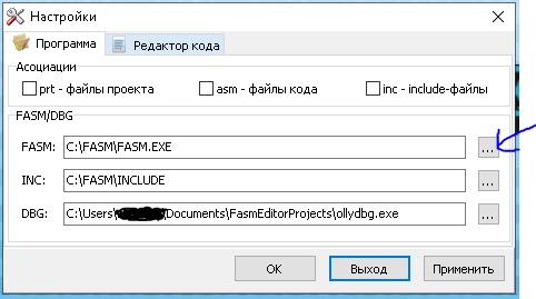
Жмем на кнопку с названием «…» и выбираем путь к файлам или папкам.
Теперь мы полностью готовы. К началу.
Пишем «Hello world!» на FASM
В Fasm Editor нужно нажать на кнопку слева сверху или «файл» -> «новый». Выбираем любое, но можно выбрать «Console»
По началу вас это может напугать, но не боимся и разбираемся.
format PE Console ; говорим компилятору FASM какой файл делать

entry start ; говорим windows-у где из этой каши стартовать программу.

include 'win32a.inc' ; подключаем библиотеку FASM-а
;можно и без нее но будет очень сложно.

section '.data' data readable writeable ; секция данных

	hello db 'hello world!',0 ; наша строка которую нужно вывести

section '.code' code readable writeable executable ; секция кода

start: ; метка старта
	invoke printf, hello ; вызываем функцию printf

  invoke getch ; вызываем её для того чтоб программа не схлопнулась
  ;то есть не закрылась сразу.

  invoke ExitProcess, 0 ; говорим windows-у что у нас программа закончилась
  ; то есть нужно программу закрыть (завершить)

section '.idata' data import readable ; секция импорта
        library kernel, 'kernel32.dll', ; тут немного сложней, объясню чуть позже
                msvcrt, 'msvcrt.dll'

  import kernel,
  				ExitProcess, 'ExitProcess'

  import msvcrt,
  				printf, 'printf',
          getch, '_getch'
На самом деле из всей этой каши текста, команд всего 3: на 16, 18, 21 строках. (и то это не команды, а макросы. Мы к командам даже не подобрались)
Все остальное это просто подготовка программы к запуску.
Программа при запуске должна выглядеть так:
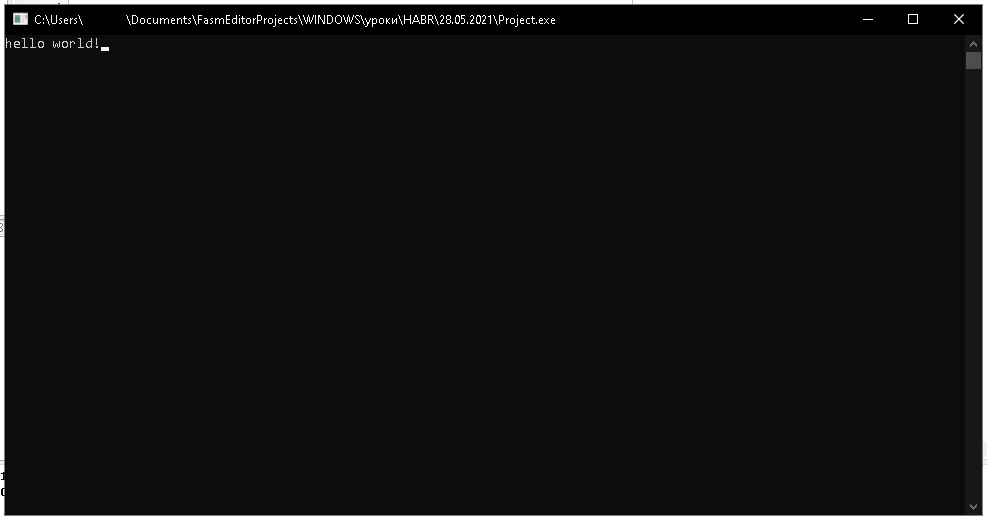
Самое интересное то что программа весит 2КБ. (Можно сократить и до 1КБ, но для упрощения и так пойдет)
Разбор: что значат этот весь текст?
На 1 строчке: «format PE Console» — это строчка говорит FASM-у какой файл скомпилировать, точнее 1 слово, все остальные слова это аргументы (можно так сказать).
PE — EXE файл, программа.
Console — говорим что это у нас консольная программа, но вам некто не мешает сделать из консольной программы оконную и наоборот.
Но есть кроме это остальные:
-
format MZ — EXE-файл НО под MS-DOS
-
format PE — EXE-файл под Windows, аналогично format PE GUI 4.0
-
format PE64 — EXE-файл под Windows, 64 битное приложение.
-
format PE GUI 4.0 — EXE-файл под Windows, графическое приложение.
-
format PE Console — EXE-файл под Windows, консольная программа. (просто подключается заранее консоль)
-
format PE Native — драйвер
-
format PE DLL — DLL-файл Windows, поясню позднее.
-
format COFF — OBJ-файл Linux
-
format MS COFF — аналогично предыдущему
-
format ELF — OBJ-файл для gcc (Linux)
-
format ELF64 — OBJ-файл для gcc (Linux), 64-bit
Сразу за командой (для компилятора) format PE Console идет ; это значит комментарий. К сожалению он есть только однострочный.
3 строка: entry start
-
Говорим windows-у гдев каком месте стартовать. «start» это метка, но о метках чуть позже.
5 строка: include 'win32a.inc'
-
Подключает к проекту файл, в данном случае «win32a.inc» он находиться в папке INCLUDE (в папке с FASM). этот файл создает константы и создает макросы для облегчения программирования.
8 строка: section '.data' data readable writeable
-
Секция данных, то есть программа делиться на секции (части), к этим секциям мы можем дать разрешение, имя.
Флаг «data» (Флаг это битбайтаргумент хранившей в себе какую-то информацию) говорит то что эта секция данных.
Флаги «readable writeable» говорят то что эта секция может читаться кем-то и записываться кем-то.
Текст ‘.data’ — имя секции
10 строка: hello db 'hello world!',0
hello — это метка, она может быть любого имени (почти, есть некоторые зарезервированные имена), эта метка хранит в себе адрес строки, это не переменная, а просто адрес, но чтобы не запоминать адреса в ручную, помогает FASM он запоминает адрес и потом когда видит эту метку снова, то он заменяет слово на адрес.
db — говорит то что под каждый символ резервируем 1 байт. То есть 1 символ храниться в одном байте.
‘hello world!’ — наша строка в кодировке ASCII
Что значит «,0» в конце строки? — это символ с номером 0 (или просто ноль), у вас на клавиатуре нет клавиши которая имела символ с номером 0, по этому этот символ используют как показатель конца строки. То есть это значит конец строки. Просто ноль записываем в байт после строки.
12 строка: section '.code' code readable writeable executable
Флаг «code» — говорит то что это секция кода.
Флаг «executable» — говорит то что эта секция исполняема, то есть в этой секции может выполняться код.
Все остальное уже разобрали.
14 строка: start:
Это второй вид меток. Просто эта метка указывает на следующую команду. Обратите внимание на то что в 3 строке мы указали start как метку входа в программу, это она и есть. Может иметь эта метка любое имя, главное не забудьте ваше новое имя метки вписать в entry
15 строка: invoke printf, hello
-
Функция printf — выводит текстчисло в консоль. В данном случае текст по адресу «hello»
Это штото на подобие команды, но это и близко не команда ассемблера, а просто макрос.
Макрос — Это макро команда для компилятора, то есть вместо имени макроса подставляется что-то другое.
Например, макро команда invoke делиться на такие команды: (взят в пример команда с 15 строки)
push hello
call [printf]
Не переживайте если нечего не поняли.
17 строка: invoke getch
-
getch — функция получения нажатой кнопки, то есть просто ждет нажатия кнопки и потом возвращает нажатую кнопку.
20 строка: invoke ExitProcess, 0
-
ExitProcess — WinAPI функция, она завершает программу. Она принимает значение, с которым завершиться, то есть код ошибки, ноль это нет ошибок.
23 строка: section '.idata' data import readable
Флаг «import» — говорит то что это секция импорта библиотек.
24-25 строки:
library kernel, 'kernel32.dll',
msvcrt, 'msvcrt.dll'-
Макро команда «library» загружает DLL библиотеки в виртуальную память (не в ОЗУ, вам ОЗУ не хватит чтоб хранить всю виртуальную память).
Что такое DLL объясню позже.
kernel — имя которое привязывается к библиотеке, оно может быть любым.
Следующий текст после запятой: 'kernel32.dll' — это имя DLL библиотеки который вы хотите подключить.
Дальше есть знак это значит что текст на следующей строке нужно подставить в эту строку.
То есть код:
library kernel, 'kernel32.dll',
  				msvcrt, 'msvcrt.dll'
Заменяется на:
library kernel, 'kernel32.dll', msvcrt, 'msvcrt.dll'Это нужно потому что у ассемблера 1 строка это 1 команда.
27-28 строка:
import kernel,
  			ExitProcess, 'ExitProcess'
import — Макро команда, которая загружает функции из DLL.
kernel — Имя к которой привязана DLL, может быть любым.
ExitProcess — Как будет называться функция в программе, это имя будет только в вашей программе, и по этому имени вы будете вызывать функцию. (WinAPI функция)
'ExitProcess' — Это имя функции которое будет загружено из DLL, то есть это имя функции которое прописано в DLL.
Дальше думаю не стоит объяснять, вроде все понятно.
Что такое DLL библиотека?
Это файл с расширением DLL. В этом файле прописаны функции (какие ни будь). Это обычная программа, но которая не запускается по двойному щелчку, а загружается к программе в виртуальную память, и потом вызываются функции находящиеся в этой DLL.
Подводим итог
На ассемблере писать можно не зная самого языка, а используя всего лишь макро команды компилятора. За всю статью я упомянул всего 2 команды ассемблера это push hello и call [printf] . Что это значит расскажу в следующей статье.
Основы ассемблера x86
Содержание
- Предисловие и как использовать эту справку
- Туториал
- Ассемблер
- Что это?
- Данные
- Регистры
- Стек
- Функции
- Условия
- Строки и массивы
- Циклы
- FASM
- Что это?
- Типы данных
- Метки
- Константы
- Макросы
- Инклуды
- Колибри ОС
- Что это?
- Как взаимодействовать?
- Привет мир!
- События
- Кнопки
- Ассемблер
- Справочные материалы
- Регистры
- Регистры общего назначения
- Флаги
- Другие
Предисловие и как использовать эту справку
Справка разделена на 2 части: туториал и таблицы. В таблицах, пока что, самое важно и то, что было мне не лень скопировать и расписать настолько подробно, насколько я мог. Все остальное в ресурсах
Туториал
Ассемблер
Что это?
Язык Ассемблера лишь перевод комманд из байткода, который умеет читать процессор на английский. MOV же говорит чуть больше. чем 0x8E. Ассемблер же — компилятор, переводящий наш код в формате ASCII-текста в байткод
Данные
Из базового курса информатики известно, что у процессора есть доступ к оперативной памяти (ОЗУ). Оттуда мы можем считывать и туда записывать данные по определенному адресу. Доступ к Постоянным Запоминающим Устройствам (ПЗУ) выполняется чуть хитрее — через прерывания BIOS или Операционной Системы
⚠️ Что код, что данные — одно и тоже. Будьте аккуратны и не позвольте процессору пытаться выполнять то, что задумывалось как данные
Регистры
Регистры — ячейки памяти небольшого размера (1-4 байта) в процессоре для вычислений. То есть все вычисления (сложение, умножение, логические операции…) происходят именно в регистрах.
Если есть некие числа в оперативной памяти, с которыми надо выполнить какие-либо операции, например, сложить, надо обязательно одно из них переместить в регистр.
Регистры бывают разные, о чем можно видеть в таблице. Работу с некоторыми будет в дальнейшем показано
Стек

Стек — форма хранения данных, движащаяся со старших, заканчивая младшими адресами.
В переводе — стопка. Представьте стопку тарелок: сначала красная, потом положили зеленую, потом синюю. Если мы начнем доставать тарелки, то в обратном порядке — синяя, зеленая, красная.
Стек играет важную роль в программировании на Ассемблере, ведь такая структура удобна для:
- Временного хранения данных (локальные переменные)
- Передачи данных другим кускам кода
Допустим, если в регистрах хранятся важные данные, но регистры нужны для выполнения каких-то операций, мы можем просто положить в стек значения регистров, положить в регистры новые данные, обработать, вернуть значения из стека:
; Сохраняем значения
push eax    ; Стек: (другие данные), eax
push ebx    ; Стек: (другие данные), eax, ebx

; Делаем какие-то операции
mov eax, 5
mov ebx, 4
add eax, ebx

; Возвращаем на место значения
pop ebx     ; Стек: (другие данные), eax
pop eax     ; Стек: (другие данные)
Функции
Точнее, их реализация на ассемблере.
Вот есть функция func делающая какие-то важные операции:
func:   ; Это метка, о них далее в разделе про FASM
	mov eax, 5
	mov ebx, 4
	add eax, ebx
	ret
Чтобы вызвать функцию используется call <метка/адрес>. Процессор перейдет на начало функции и начнет его выполнять, а адрес следующей после call команды поместится в стек. Зачем? Мы же хотим вернуться обратно после выполнения функции, а для этого используется команда ret в конце функции — вытаскивает из стека адрес и заставляет процессор вернуться туда
ℹ️ «Функция» просто для упрощения объяснения. Естественно в ассемблере функций нет
Условия
В x86 существует команда CMP (compare). Смысл в ней в том, чтобы сравнивать 2 цисла. Результат записывается во флаги.
mov eax, 4
mov ebx, 5
cmp eax, ebx
Списки и массивы
По сути это тоже будет абстракцией, ведь в памяти все данные одинаковы
db "Meow!", 0
dw 1, 43, 510
В памяти будет 4D656F7700 и 01002B00FE01. Во втором каждый «элемент» занимает 2 байта, поэтому обращение к ним будет по базовому адресу (адресу первого элемент) + 2*индекс. Из-за этого индекс первого элемента — 0
Циклы
For цикл:
mov ecx, 10

@@: ; Это анонимная метка, о них потом тоже раскажу
	call some_func
loop @b
Будет вызывать функцию 10 раз
Foreach цикл:
str db "Meow", 0
mov eax, str

; eax - значение регистра eax
; [eax] - значение ячейки памяти по адресу eax
@@:
	add byte [eax], 2  ; Сдвигаем символ на 2 (M -> 0...)
	inc eax            ; Переходим к следующему символу
	cmp [eax], 0       ; Сравниваем символ по адресу eax с 0
	jne @b             ; Если до конца не дошли - производим следующую итерацию
While цикл:
mov eax, 1
@@:
	imul eax, eax, 2
	cmp eax, 1000
	jng @b
Что это?
Как я уже говорил, ассемблер — компилятор кода, написанного на языке ассемблера. Компиляторы бывают разные: различаются синтаксисом и платформами. Один из них — FASM (flat assembler)
Типы данных
| Тип | префикс | размер в байтах |
размер в битах |
|---|---|---|---|
| byte | b | 1 | 8 |
| word | w | 2 | 16 |
| double word | d | 4 | 32 |
d<префикс> — объявление
db 34, 5
dw 1024
в бинарном файле станет 22050004
r<префикс> — займет место
rb 5
rd 2
в бинарнике станет 00000000000000000000000000
Метки
Метки есть 3х типов:
start:
	mov eax, ...
@@:
	mov ebx, ...
cool_string db "Hello world!", 0
Метка ассемблируется в просто адрес, где мы его поставили. Например:
start:
	...
jmp start:
ассемблируется в E848, где 48, в моем случае, адрес start
Анонимные метки нужны для тех случаев, когда, например, лень придумывать имя, да оно и не будет более одного раза использовать.
@@— объявление анонимной метки@f— следующая в коде анонимная метка@b— предыдущая в коде анонимная метка
Константы
Константы, очевидно, некие значения, которые являются постоянными. Чтобы не сохранять их в памяти, как переменные, но были чем-то одним в разных частях программы, но при изменении константы не пришлось значения изменять во всем коде, можно сделать так:
G equ 667430
...
mov eax, G
Не совсем константы, но стоит упомянуть, что можно заставить FASM на этапе препроцессинга не только подставлять контстанты, но и вычислять математические выражения:
mov eax, 4*45+3
ℹ️ Все вычисления в правильном порядке
Макросы
macro macro_name {
	mov eax, 5
	mov ebx, 4
	add eax, ebx
}
, то macro_name на этапе препроцессинга заменится на содержимое макроса
Инклуды
.inc файлы, из которых берутся константы и макросы на этапе препроцессинга
Колибри ОС
Что это?
Я не буду пересказывать всю историю сей ОСи. Вкратце: написанная на ассемблере ОСь, в котором просто можно делать графические приложения на, собственно, ассемблере, что очень подходит для обучения
Как взаимодействовать
Для взаимодействия в ОСью существуют системные вызовы, которые описаны на Вики
Привет мир!
use32	; Используем 32 бита
org 0	; Адресация с нуля

db "MENUET01"	; Индентификатор
dd 1			; Версия заголовка
dd _start		; Адрес начала программы
dd _end			; Адрес конца программы
dd _stack		; Адрес конца стека
dd _mem			; Адрес конца доступной памяти
dd 0			; Адрес буфера для параметров
dd 0			; Так надо (зарезервировано)

_start:
    mov eax, 0			; Системный вызов для создания окна
    mov ebx, 200		; Ширина в 200 пикселей
    mov ecx, 100		; Высота в 100 пикселей
    mov edx, 0x321E1E1E ; 1й тип окна, размеры от начала экрана, есть заголовок, цвет залития - 1E1E1E
    mov esi, 0x002A2E32 ; без градиента, перемещаемое, цвет заголовка - 2A2E32
    int 40h				; Вызываем

    mov eax, 4			; Системный вызов для вывода на окно строки
    mov ebx, 5*65536+5	; Отступ в 5 пк по X и Y
    mov ecx, 0xB0FFFFFF ; Строка заканчиается нулем, не закрашивать фон, UTF-8, рисовать в окно. размер шрифта - самый мелкий
    mov edx, hw			; Сама строка
    int 40h				; Вызываем

    mov eax, 10			; Ждем события (просто чтобы не закрывалось окно сразу)
    int 40h

    mov eax, -1			; Закрываемся
    int 40

hw db "Hello, Kolibri!", 0

_end:
_stack:
_mem:
Та же программа, но со стандартным инклудом:
include "marcos.inc"

KOS_APP_START

CODE                                            ; Секция кода
_start:
    mcall 0, 200, 100, 0x321E1E1E, 0x002A2E32   ; Создать окно 200х100
    mcall 4, 5*65536+5, 0xB0FFFFFF, hw          ; Вывести текст [hw] по координатам (5, 5)
    mcall 10                                    ; Подождать какого-либо события (чтоб окно не закрылось сразу)
    mcall -1                                    ; Корректно завершить работу программы

DATA                                            ; Секция инициализированных данных
hw db "Hello, Kolibri!", 0

UDATA                                           ; Секция неинициализированных данных... наверно...
                                                ; Да, объявлять эту секцию обязательно
KOS_APP_END
Справочные материалы
Регистры
Регистры общего назначения (РОН)
| 32-битные | 16-битные | 8-битные |
|---|---|---|
| EAX | AX | AH, AL |
| EBX | BX | BH, BL |
| ECX | CX | CH, CL |
| EDX | DX | DH, DL |
| ESI | SI | SIL |
| EDI | DI | DIL |
| ESP | SP | SPL |
| EBP | BP | BPL |
- AX — Accumulator
- BX — Base Register
- CX — Count Register
- DX — Data Register
- SI — Source Index
- DI — Destination Index
- SP — Stack Pointer
- BP — Base Pointer
   Байты:
|3 |2 |1 |0 |
|     |AH|AL|
|     |  AX |
|    EAX    |
Т.е. если EAX = 0x01020304, то AX = 0x0304, AH = 0x03, AL = 0x04
Аналогично с другими регистрами
Флаги
Флаги — это набор битов, объединенные в единый регистр (E)FLAGS, необходимыые для определения условий
В отличие от РОН к флагам нет прямого доступа (мы не можем напрямую записать какое-либо значение), но флаги влияют на поведение некоторых комманд, о которых далее
Перечислю самое необходимое. Остальное на Вики
| Бит | Обозначение | Название | На русском |
|---|---|---|---|
| 0 | CF | Carry Flag | Флаг переноса |
| 2 | PF | Parity Flag | Флаг четности |
| 6 | ZF | Zero Flag | Флаг нуля |
| 11 | OF | Overflow Flag | Флаг переполнения |
Другие
- EIP — указатель команды, исполняемая на следующем шаге
- MMX (MM0-MM7) — регистры расширения MMX. По версии Вики считаются устаревшими
- ST0-ST7 — регистры, образующие стек модуля математического сопроцессора для операций с плавающей точкой (FPU). Короче: регистры для вычисления дробных чисел
Команды общего назначения
Условные обозначения:
r— регистрm— память (т.е. некая информация, находящаяся в оперативной памяти, дост к которому получаем по его адресу)n— числоW+— значение размером word и большеD+— значение размером dword и больше[r][m], [r, m, n][r, n]—[r]с[r, m, n],[m]с[r, n]
Команды передачи данных
MOV
Присваивание
MOV dst[r][m], src[r, m, n][r, n]
dst— Куда пересылаются данныеsrc— Откуда берутся данные
	mov EAX, 4      ; EAX = 4
	mov EBX, 5      ; EBX = 5
	mov EAX, EBX    ; EAX = 5, EBX = 5

	mov EBX, 3
	mov [20h], ebx  ; 20h: 0x3
	mov EAX, [20h]  ; EAX = 3
CMOVxx
Присваивание при условии xx
Аналлогично MOV
PUSH
Помещение в стек
PUSH src[r, n, m]W+
POP
Взятие из стека
POP dst[r, m]W+
PUSHA/PUSHAD
Перемещение в стек регистров общего назначения
PUSHA
POPA/POPAD
Взятие из стека регистров общего назначения
POP
Арифметические команды
ADD
Сложение
ADD dst[r][m], src[r, m, n][r, n]
dst— Первое слагаемое и суммаsrc— Второе слагаемое
	mov eax, 4          ; EAX = 4
	mov ebx, 5          ; EBX = 5
	add eax, ebx        ; EAX = 9, EBX = 5

	; EAX - 4 байта - dword
	mov [20h], eax      ; [20h] = 0x9
	add dword [20h], 3  ; [20h] = 0xC
SUB
Вычитание
SUB dst[r][m], src[r, m, n][r, n]
dst— Уменьшаемое и разностьsrc— Вычитаемое
остальное потом допишу
Условия
| Мнемоника | Условие | Флаг |
|---|---|---|
| о | переполнение | OF=1 |
| no | нет переполнения | OF=0 |
| c b nae |
перенос ниже не выше, не равно |
CF=1 |
| nc ae nb |
нет переноса выше или равно не ниже |
CF=0 |
| e z |
равно ноль |
ZF=1 |
| ne nz |
неравно не ноль |
ZF=0 |
| be na |
ниже или равно не выше |
CF or ZF = 1 |
| a nbe |
выше не ниже, не равно |
CF or ZF = 0 |
| s | отрицательное число | SF=1 |
| ns | положительное число | SF=0 |
| p pe |
четное четное число ненулевых битов |
PF=1 |
| np po |
нечетное | PF=0 |
| l nge |
меньше не больше, не равно |
SF xor OF = 1 |
| ge nl |
больше или равно не меньше |
SF xor OF = 0 |
| le ng |
меньше или равно не больше |
(SF xor OF) or ZF = 1 |
| g nle |
больше не меньше, не равно |
(SF xor OF) or ZF = 0 |
Ресурсы
- http://www.ccfit.nsu.ru/~kireev/lab2/lab2com.htm
- http://kolibri-n.org/inf/hll/hll.php#fasm
- http://wiki.kolibrios.org/wiki/Ru/api/kernel
-

Mikl___
Супермодератор
Команда форума- Публикаций:
-
14
- Регистрация:
- 25 июн 2008
- Сообщения:
- 3.531
Руководство по препроцессору FASM
перевод TAJGA FASM Tutorial by vid — FASM preprocessor guide
перевел S.T.A.S.Содержание
- Об этом документе
- Общие понятия
- 2.1. Что такое препроцессор
- 2.2. Комментарии «;«
- 2.3.Перенос строки ««
- 2.4. Директива «INCLUDE«
- Присваивания
- 3.1. Директива «EQU«
- 3.2. Директива «RESTORE«
- Простые макросы без аргументов
- 4.1. Определение простых макросов
- 4.2. Вложенные макросы
- 4.3. Директива «PURGE» (отмена определения макроса)
- 4.4. Поведение макросов
- Макросы с фиксированным количеством аргументов
- 5.1. Макросы с одним аргументом
- 5.2. Макросы с несколькими аргументами
- 5.3. Директива «LOCAL«
- 5.4. Оператор объединения «#»
- 5.5. Оператор «`«
- Макросы с групповыми аргументами
- 6.1. Определение макросов с групповым аргументом
- 6.2. Директива «COMMON«
- 6.3. Директива «FORWARD«
- 6.4. Директива «REVERSE«
- 6.5. Комбинирование директив управления группами
- 6.6. Директива «LOCAL» в макросах с групповыми аргументами
- 6.7. Макросы с несколькими групповыми аргументами
- Условный препроцессинг
- 7.1. Оператор «EQ«
- 7.2. Оператор «EQTYPE»
- 7.3. Оператор «IN«
- Структуры
- Оператор FIX и макросы внутри макросов
- 9.1. Explaination of fixes
- 9.2. Using fixes for nested macro declaration
- 9.3. Using fixes for moving part of code
- Заключение
Последнее редактирование: 10 дек 2016
-
Mikl___
Супермодератор
Команда форума- Публикаций:
-
14
- Регистрация:
- 25 июн 2008
- Сообщения:
- 3.531
1. Об этом документе
Я написал это потому что вижу, как многие задают вопросы на форуме FASM, связанные с непониманием идей или особенностей препроцессора. (Я не отговариваю Вас задавать такие вопросы, непонимание чего-то — это вполне нормально, и если Ваш вопрос не чересчур сложен, кто-нибудь наверняка на него ответит).Если Вам что-нибудь из туториала покажется непонятным, пожалуйста, напишите на форум FASM, форум WASM, автору или переводчику.
2. Общие понятия
2.1. Что такое препроцессор
Препроцессор — это программа (или чаще — часть компилятора), которая преобразует исходный текст непосредственно перед компиляцией. К примеру, если Вы используете какой-либо кусок кода довольно часто, можно дать ему некое имя и заставить препроцессор повсеместно заменять это имя в исходном тексте на соответствующий ему код.Другой пример — Вы хотите имитировать инструкцию, которая на самом деле не существует. В таком случае препроцессор может заменять её последовательностью инструкций дающих желаемый эффект.
Препроцессор просматривает исходный текст и заменяет некоторые вещи другими. Но как объяснить препроцессору, что именно он должен делать? Для этих целей существуют директивы препроцессора. О них мы и будем говорить.
Препроцессор понятия не имеет о инструкциях, директивах компилятора и прочих подобных вещах. Для него существуют собственные команды, и он игнорирует всё остальное.
2.2. Комментарии «;»
Подобно большинству ассемблеров, комментарии в FASM начинаются с точки с запятой «;«. Всё, что следует за этим символом до конца строки игнорируется и удаляется из исходника.
К примеру, исходный текст
-
; заполним 100h байтов адресуемых EDI нулями
-
xor eax, eax ; обнуляем eax
после препроцессора превращается в
ПРИМЕЧАНИЕ: ; можно рассматривать как директиву препроцессора, удаляющую текст начиная с этого символа до конца строки.
ПРИМЕЧАНИЕ: Строка, полностью состоящая из комментария не будет удалена. Она становится пустой строкой (см. пример выше). Это будет важно в дальнейшем.
2.3. Перенос строки (Line Break «»)
Если строка выглядит слишком длинной, возможно разделить её на несколько, используя символ ««. При обработке препроцессором следующая строка будет добавлена к текущей.
Например:
будет преобразовано в:
Конечно, в составе текстовой строки или комментария не вызовет объединения строк. Внутри текстовой строки этот символ воспринимается как обычный ASCII символ (как и всё остальное заключённое между кавычками ‘ или «). Комментарии же удаляются без анализа того, что в них написано.
В строке после символа могут быть только пробелы или комментарии.
Ранее, я упоминал, что строка, состоящая только из комментария не удаляется, а заменяется на пустую строку. Это значит, что код, подобный этому:
-
; 4,5,6, — закомментировано
преобразуется в:
и вызовет ошибку. Выход из положения — помещать символ до комментария:
-
; 4,5,6 — правильно закомментировано
в результате будет:
как мы и хотели.
2.4. Директива INCLUDEСинтаксис:
-
include <некая строка содержащая имя файла file_name>
Эта директива вставляет содержимое файла file_name в исходный текст. Вставленный текст, естественно, тоже будет обработан препроцессором. Имя файла (и путь к нему, если он есть) должны быть заключены в кавычки « или апострофы ‘.
Например:-
include ‘HEADERSdata.inc’
-
include ‘..libstrings.asm’
Можно также использовать переменные окружения ОС, помещая их имена между символами %:
-
include ‘%FASMINC%win32a.inc’
-
include ‘%SYSTEMROOT%somefile.inc’
-
include ‘%myproject%headerssomething.inc’
-
include ‘C:%myprojectdir%headerssomething.inc’
2.5. Strings preprocessing
You may have problem to include ‘ in string declared using ‘s or « in string declared using «s. For this reason you must place the character twice into string, in that case it won’t end string and begin next as you may think, but it will include character into string literaly.Например:
will generate binary containing string It’s okay.
It’s same for «.3. Присваивания (Equates)
3.1. Директива EQU
Простейшая команда препроцессора.
Синтаксис:
Это команда говорит препроцессору, что необходимо заменить все последующие <name1> на <name2>.
Например:-
count equ 10 ; это команда препроцессора
преобразуется в:
Ещё пример:
преобразуется в:
потому что препроцессор заменит count только после директивы equ.
Даже это работает:после обработки препроцессором, получим:
Обратите внимание, name1 может быть любым идентификатором. Идентификатор — это всего лишь набор символов, завершаемый пробелом (space), символом табуляции (tab), концом строки (EOL), комментарием ;, символом переноса строки или оператором, включая операторы ассемблера и/или специальные символы вроде , или }.
name2 может быть не только единичным идентификатором, берутся все символы до конца строки. name2 может и отсутствовать, тогда name1 будет заменен на пустое место.
Например:получим:
3.2. Директива RESTORE
Можно заставить препроцессор прекратить заменять идентификаторы, определённые директивой EQU. Это делает директива RESTORE
Синтаксис:name1 — это идентификатор определённый ранее в директиве EQU. После этой команды name1 больше не будет заменяться на name2.
Например:получим:
Обратите внимание, что для определений сделанных директивой EQU работает принцип стека. То есть, если мы два раза определим один и тот же идентификатор используя EQU, то после однократного использования RESTOREзначение идентификатора будет соответствовать определённому первой директивой EQU.
Например:получим:
Если попытаться выполнить RESTORE большее количество раз, чем было сделано EQU, никаких предупреждений выдано не будет. Значение идентификатора будет неопределенно.
Например:получим:
Последнее редактирование: 10 дек 2016
-
Mikl___
Супермодератор
Команда форума- Публикаций:
-
14
- Регистрация:
- 25 июн 2008
- Сообщения:
- 3.531
4. Простые макросы без аргументов
4.1. Определение простых макросов
Использую EQU можно делать наиболее простые замены в исходном тексте при обработке препроцессором. Большими возможностями обладают макросы. Командой MACRO можно создавать собственные инструкции.
Синтаксис:
Когда препроцессор находит директиву macro, он определяет макрос с именем name. Далее, встретив в исходном тексте строку, начинающуюся с name, препроцессор заменит name на тело макроса — то, что указано в определении между скобками { и }. Имя макроса может быть любым допустимым идентификатором, а тело макроса — всё, что угодно, за исключением символа }, который означает завершение тела макроса.
Например:будет заменено на:
Или:
получим:
Разумеется, макросы не обязательно оформлять так, как выше, можно делать и так:
-
macro push5 {push dword 5}
получим:
Или:
-
macro push5 {push dword 5
с тем же самым результатом. Скобочки можете размещать как хотите.
4.2. Вложенные макросы
Макросы могут быть вложенными один в другой. То есть, если мы переопределим макрос, будет использовано последнее определение. Но если в теле нового определения содержится тот же макрос, то будет использовано предыдущее определение. Посмотрите пример:
в результате получим:
Или такой пример:
получим:
4.3. Директива PURGE. Отмена определения макроса
Как и в случае с директивой EQU, можно отменить определение макроса. Для этого используется директива PURGE с указанием имени макроса.
Синтаксис:
Пример:
получим:
Если применить PURGE к несуществующему макросу, ничего не произойдёт.
4.4. Поведение макросовИмя макроса будет заменено его телом не только в том случае, если оно расположено в начале строки. Макрос может находиться в любом месте исходного текста, где допустима мнемоника инструкции (например, add или mov). Всё потому, что основное предназначение макросов — имитировать инструкции. Единственное исключение из этого правила — макросы недопустимы после префиксов инструкций (rep).
Пример:
-
a: CheckErr ; здесь макросу предшествует метка, всё Ок.
получим:
Пример #2:
-
stos0 ;это место инструкции, будет замена.
-
here: stos0 ;это тоже место инструкции.
-
db stos0 ;здесь инструкции не место, замены не будет.
получим:
Возможно переопределять (overload) инструкции посредством макросов. Так как препроцессор ничего об инструкциях не знает, он позволяет использовать мнемонику инструкции в качестве имени макроса:
-
push eax ebx ecx edx ebp esi edi
-
pop edi esi ebp edx ecx ebx eax
эти две новые инструкции будут экономить по четыре байта в стеке, так как не сохраняют ESP (правда, занимают побольше места, чем реальные инструкции
. Всё же, переопределение инструкций не всегда хорошая идея — кто-нибудь читая Ваш код может быть введён в заблуждение, если он не знает, что инструкция переопределена.
Также, возможно переопределять директивы ассемблера:5. Макросы с фиксированным количеством аргументов
5.1. Макросы с одним аргументом
Макросы могут иметь аргумент. Аргумент представляет собой какой-либо идентификатор, который будет повсюду заменён в теле макроса тем, что будет указанно при использовании.
Синтаксис:
-
macro <name> <argument> { <тело макроса> }
Например:
получим:
-
add ds, 5 ;такой инструкции не существует
-
;но препроцессор это не волнует.
-
;ошибка появится на стадии ассемблирования.
-
add ds+2,5 ;ошибка синтаксиса, как и ранее
-
;определится при анализе синтаксиса (parsing).
(разумеется, комментарии в результате работы препроцессора не появятся
5.2. Макросы с несколькими аргументамиУ макросов может быть несколько аргументов, разделённых запятыми «,«:
преобразуется в:
Если несколько аргументов имеют одно и тоже имя, то будет использован первый из них
.
Если при использовании макроса указать меньше аргументов, чем при определении, то значения неуказанных будет пустым:-
macro pupush a1, a2, a3, a4
Если в аргументе макроса необходимо указать запятую как символ («,«), тогда необходимо аргумент заключить в скобочки из символов < и >.
-
macro safe_declare name, what
-
safe_declare array5, <dd 1,2,3,4,5>
-
safe_declare string, <db «привет, я просто строка»,0>
получим:
-
string db «привет, я просто строка»,0
Конечно же, можно использовать символы < и > и внутри тела макроса:
-
macro b arg1,arg2 {a <arg1,arg2,3>}
5.3. Директива «LOCAL»
Возможно, появится необходимость объявить метку внутри тела макроса:
-
call behind ;помещаем в стек адрес string и переходим к behind
но если использовать такой макрос 2 раза, то и метка behind будет объявлена дважды, что приведёт к ошибке. Эта проблема решается объявлением локальной метки behind. Это и делает директива LOCAL.
Синтаксис:Директива должна применяться внутри тела макроса. Все метки label_name внутри макроса становятся локальными. Так что, если макрос используется дважды никаких проблем не появляется:
На самом деле, behind заменяется на behind?XXXXXXXX, где XXXXXXXX — какой-то шестнадцатеричный номер генерируемый препроцессором. Последний пример может быть преобразован к чему-то вроде:
Заметьте, Вы не сможете напрямую обратиться к метке содержащей ?, так как это специальный символ в FASM, поэтому он и используется в локальных метках. К примеру, aa?bb рассматривается как идентификатор aa, специальный символ ? и идентификатор bb.
Если Вам нужно несколько локальных меток — не проблема, их можно указать в одной директиве LOCAL, разделив запятыми:
-
macro pushstr string ;делает то же, что и предыдущий макрос
Всегда хорошо бы начинать все локальные метки макросов с двух точек .. — это значит, что они не будут менять текущую глобальную метку. К примеру
будет преобразовано в:
в результате получим метку behind?00000001.a вместо MyProc.a. Но если в примере выше behind заменить на ..behind, текущая глобальная метка не изменится и будет определена метка MyProc.a:
Последнее редактирование: 10 дек 2016
-
Mikl___
Супермодератор
Команда форума- Публикаций:
-
14
- Регистрация:
- 25 июн 2008
- Сообщения:
- 3.531
5.4. Оператор объединения #
У макроязыка FASMа есть ещё одна возможность — манипуляции с идентификаторами. Делается это оператором #, который объединяет два идентификатора в один. К примеру, a#b становится ab, а aaa bbb#ccc ddd — aaa bbbccc ddd.
Оператор # может быть использован только внутри тел макросов, а объединение символов происходит после замены аргументов макроса параметрами. Так что его можно использовать для создания новых идентификаторов из переданных в макрос параметров:
-
sizeof.#name = $ — ..start
-
string s1,‘нудные макросы’
-
string s2,<‘а вот и я’,13,10,‘заставлю тебя их видеть во сне’>
получим:
-
sizeof.s1 = $ — ..start?00000001
-
s2 db ‘а вот и я’,13,10,‘заставлю тебя их видеть во сне’,0
-
sizeof.s2 = $ — ..start?00000002
так что для всех строк, создаваемых этим макросом будет определён идентификатор sizeof.имя строки, равный количеству байт строки.
Оператор # способен так же объединять символьные строки:будет:
Это полезно при передаче аргументов из макроса в макрос:
-
pushstring ‘debug: ‘#string ;принимает один аргумент
Обратите внимание, нельзя использовать # совместно с идентификаторами, определёнными local, так как localобрабатывается препроцессором раньше, чем #. Из-за этого подобный код работать не будет:
5.5. Оператор «`«
Существует оператор, преобразующий идентификатор в символьную строку. Он так же может быть использован только внутри макросов:
-
log `name ;log — макрос, принимающий параметр-строку
получим:
Пример посложнее, с использованием «#»
-
log ‘начинается подпрограмма: ‘#`name
будет:
-
log ‘начинается подпрограмма: DummyProc’
-
log ‘начинается подпрограмма: Proc2’
6. Макросы с групповыми аргументами
6.1. Определение макросов с групповым аргументом
У макросов могут быть так называемые групповые аргументы. Это позволяет использовать переменное количество аргументов. При определении макроса, групповой аргумент заключается в квадратные скобочки «[» и «]«:
Синтаксис:
-
macro name arg1, arg2, [grouparg]
Среди аргументов в определении макроса, групповой аргумент должен быть последним. Групповой аргумент может содержать несколько значений:
-
macro name arg1,arg2,[grouparg] {}
В этом примере значение arg1 равно 1, arg2 равно 2, а grouparg равно 3,4,5 и 6
6.2. Директива «COMMON«Для работы с групповыми аргументами применяются специальные директивы препроцессора. Они могут быть использованы только внутри тела макроса имеющего групповой аргумент. Первая такая директива — это «COMMON«. Она означает, что после нее имя группового аргумента будет замещаться всеми аргументами сразу:
-
string ‘line1’,13,10,‘line2’
получим:
-
db ‘line1’,13,10,‘line2’,0
6.3. Директива «FORWARD«
Аргументы можно обрабатывать и по-отдельности. Для этого служит директива «FORWARD«. Часть тела макроса после этой директивы обрабатывается препроцессором для каждого аргумента из группы:
будет:
Директива «FORWARD» работает по умолчанию для макросов с групповыми аргументами, так что предыдущий пример можно сделать так:
6.4. Директива «REVERSE«
«REVERSE» — это аналог «FORWARD«, но обрабатывает группу аргументов в обратном порядке — от последнего к первому:
получим:
6.5. Комбинирование директив управления группами
Три вышеупомянутые директивы могут разделять тело макроса на блоки. Каждый блок обработается препроцессором после предыдущего. Например:
-
f_#grparg: ;оператор объединения
будет:
6.6. Директива LOCAL в макросах с групповыми аргументами
У локальных меток в макросах есть ещё одно полезное свойство. Если директива «LOCAL» находится внутри блока «FORWARD» или «REVERSE«, то уникальное имя метки сгенерируется для каждого аргумента из группы, и в последующих блоках «FORWARD» и/или «REVERSE» для каждого аргумента будет использована соответствующая ему метка:
-
macro string_table [string]
-
forward ;таблица указателей на строки
-
local addr ;локальная метка для строки
-
dd addr ;указатель на строку
-
addr db string,0 ;создаём и завершаем нулём
-
string_table ‘aaaaa’,‘bbbbbb’,‘5’
получим:
-
addr?00000001 db ‘aaaaa’,0
-
addr?00000002 db ‘bbbbbb’,0
Другой пример с блоком «REVERSE«:
будет:
Как видно, метки используется с соответствующими аргументами и в «FORWARD«- и в «REVERSE«-блоках.
6.7. Макросы с несколькими групповыми аргументамиВозможно использовать и несколько групповых аргументов. В этом случае определение макроса не будет выглядеть как:
так как тут не ясно какой аргумент какой группе принадлежит. Исходя из этого делают так:
В этом случае каждый нечётный аргумент относится к группе grp1, а каждый чётный — к grp2:
будет:
Или ещё:
-
macro ErrorList [name,value]
-
INTERNAL,20[/asm]получим:[code]ERROR_NONE = 0
Конечно же, может быть больше двух групп аргументов:
-
a 1,2,3,4,5,6,7,8,9,10,11
будет:
7. Условный препроцессинг
В действительности, FASM не имеет директив для условного препроцессинга. Но директива ассемблера «if» может быть использована совместно с возможностями препроцессора для получения тех же результатов, что и при условном препроцессинге. (Но в этом случае увеличивается расход памяти и времени).
Как известно, оператор «if» обрабатывается во время ассемблирования. Это значит, что условие в этом операторе проверяется после обработки исходного текста препроцессором. Именно это обеспечивает работу некоторых логических операций.Я не буду рассказывать о деталях времени ассемблирования (логических операциях вроде «&«, «|» и тому подобном) — читайте об этом в документации FASM. Я лишь расскажу об операторах проверки условия используемых препроцессором.
7.1. Оператор «EQ«Простейший логический оператор — это «EQ«. Он всего лишь сравнивает два идентификатора — одинаковы ли их значение. Значение abcd eq abcd — истина, а abcd eq 1 — ложь и так далее… Это полезно для сравнения символов, которые будут обработаны препроцессором:
-
else if STRINGS eq UNICODE
-
display ‘unknown string type’
после обработки препроцессором, это примет вид:
-
display ‘unknown string type’
Здесь только первое условие (ASCII eq ASCII) выполняется, так что будет ассемблировано только
Другой вариант:
-
STRINGS equ UNICODE ;разница здесь, UNICODE вместо ASCII
-
else if STRINGS eq UNICODE
-
display ‘unknown string type’
получим:
-
else if UNICODE eq UNICODE
-
display ‘unknown string type’
Тут уже первое условие (UNICODE eq ASCII) будет ложно, второе (UNICODE eq UNICODE) — верно, будет ассемблироваться
Последнее редактирование: 10 дек 2016
-
Mikl___
Супермодератор
Команда форума- Публикаций:
-
14
- Регистрация:
- 25 июн 2008
- Сообщения:
- 3.531
Несколько лучшее применение этого — проверка аргументов макросов, вроде:
-
item STRING,‘aaaaaa’[/asm]будет:[code=asm]if BYTE eq BYTE
-
end if[/asm]ассемблироваться будут только две команды:[code=asm]db 1
Подобно всем другим операторам препроцессора, «EQ» может работать с пустыми аргументами. Это значит, что, например, «if eq» верно, а if 5 eq — ложно и тому подобное. Пример макроса:
здесь, если есть третий аргумент, то будут ассемблироваться две последних команды, если нет — то только первая.
7.2. Оператор «EQTYPE»
Ещё один оператор — «EQTYPE». Он определяет, одинаков ли тип идентификаторов.
Существующие типы:- отдельные строки символов, заключённые в кавычки (те, которые не являются частью численных выражений)
- вещественные числа
- любые численные выражения, например, 2+2 (любой неизвестный символ будет рассматриваться как метка, так что он будет считаться подобным выражением)
- адреса — численные выражения в квадратных скобках (учитывая оператор размерности и префикс сегмента)
- мнемоники инструкций
- регистры
- операторы размерности
- операторы NEAR и FAR
- операторы USE16 и USE32
- пустые аргументы (пробелы, символы табуляции)
Пример макроса, который позволяет использовать переменную в памяти в качестве счётчика в инструкции SHL (например shl ax, [myvar]):
-
if count eqtype [0] ;если count — ячейка памяти
-
else ;если count другого типа
-
shl dest, count ;просто используем обычную shl
получится:
-
if [byte_variable] eqtype [0]
в результате обработки условий конечный результат будет:
Заметьте, что shl ax, byte [myvar] не будет работать с этим макросом, так как условие byte [variable] eqtype [0] не выполняется. Читаем дальше.Когда мы сравниваем что-то посредством «EQTYPE», то это что-то может быть не только единичным идентификатором, но и их комбинацией. В таком случае, результат eqtype истина, если не только типы, но и порядок идентификаторов совпадают. К примеру, if eax 4 eqtype ebx name — верно, так как name — это метка, и её тип — численное выражение.Пример расширенной инструкции mov, которая позволяет перемещать данные между двумя ячейками памяти:
-
if dest src eqtype [0] [0]
преобразуется препроцессором в:
-
if [var1] 5 eqtype [0] [0] ;не верно
-
if [var1] [var2] eqtype [0] [0] ;верно
и будет ассемблировано в:
Хотя более удобно для восприятия реализовать макрос используя логический оператор И — &:
-
if (dest eqtype [0]) & (src eqtype [0])
Пример с использованием «EQTYPE» с четырьмя аргументами приведён для демонстрации возможностей, обычно проще использовать в таких случаях «&». Кстати, в качестве аргументов, возможно использовать некорректные выражения — достаточно, чтобы лексический анализатор распознал их тип. Но это не является документированным, так что не будем этот обсуждать.
7.3. Оператор «IN»
Бывают случаи, когда в условии присутствует слишком много «EQ«:-
if (a eq cs) | (a eq ds) | (a eq es) | (a eq fs) |
Вместо применения множества логических операторов ИЛИ — |, можно использовать специальный оператор «IN«. Он проверяет, присутствует ли идентификатор слева, в списке идентификаторов справа. Список должен быть заключён в скобочки «<» и «>«, а идентификаторы в нём разделяются запятыми:
-
if a in <cs,ds,es,fs,gs,ss>
Это так же работает для нескольких идентификаторов (как и «EQ»):
-
if dword [eax] in <[eax], dword [eax], ptr eax, dword ptr eax>
8. Структуры
В FASM, структуры практически тоже самое, что и макросы. Определяются они посредством директивы STRUC:
Синтаксис:-
struc { <тело структуры> }
Отличие от макросов заключается в том, что в исходном тексте перед структурой должна находиться некое «имя» — имя объекта-структуры. Например:
это не будет работать. Структуры распознаются только после имен, как здесь:
подобно макросу, это преобразуется препроцессором в:
Смысл имени в следующем — оно будет добавлена ко всем идентификаторам из тела структуры, которые начинаются с точки. Например:
-
name2 a[/asm]будет:[code=asm]name1.local:
Таким образом можно создавать структуры вроде тех, что есть в языках высокого уровня абстракции:
-
struc rect left,right,top,bottom ;аргументы как у макроса
-
r2 rect ?,?,?,?[/asm]получим:[code=asm]r1.left dd 0
Поскольку, используемой структуре всегда должно предшествовать имя, препроцессор однозначно отличает их от макросов. Поэтому имя структуры может совпадать с именем макроса — в каждом случае будет выполняться нужная обработка.Существуют хитрый приём, позволяющий не указывать аргументы, если они равны 0:
-
y2 ymmv[/asm]будет:[code=asm]y1.member dd 0xACDC+0
Как говорилось ранее, если значение аргумента не указанно, то в теле макроса или структуры вместо него ничего не подставляется. В этом примере «плюс» («+») используется или как бинарный оператор (то есть с двумя операндами), или как унарный (с одним операндом) оператор.ПРИМЕЧАНИЕ: часто используется так же макрос или структура struct, которая определяется для расширения возможностей при определении структур. Не путайте struct и struc.
9. Оператор FIX и макросы внутри макросов
В стародавние времена, в FASMе отсутствовала одна полезная возможность — создавать макросы внутри других макросов. Например, что бы при развёртывании макроса был бы определён новый макрос. Что-то вроде гипотетичного:-
macro declare_macro_AAA { macro AAA { db ‘AAA’,0 } ;завершаем определение AAA } ;завершаем определение declare_macro_AAA[/asm]Проблема в том, что когда макрос[code=asm]declare_macro_AAA
обрабатывается препроцессором, первая найденная скобочка «}» считается завершением определения его, а не так как хотелось бы. Так же происходит и с другими символами и/или операторами (например, «#«, «`«, «forward«, «local«).
9.1. Explaination of fixes
Но со временем, была добавлена новая директива. Она работает подобно «EQU«, но обрабатывается до любого другого препроцессинга. (За исключением предварительных операций, про которые говорится в разделе «Общие понятия» — они выполняются как бы до самого препроцессинга, но это уже внутренние детали, не слишком интересные). Директива эта называется FIX:
Синтаксис :Видно, что синтаксис такой же как у «EQU«, но как я сказал, когда препроцессор обрабатывает часть кода, он смотрит, есть ли «FIX«, а потом уже делает всё остальное. Например код:
Then preprocesisng happens like this:
Preprocessing line 1:
a — Preprocessor finds unknown word, skips it.
equ — «equ» is second word of line, so it remembers «a» equals rest of line («b») and deletes line
Preprocessing line 2:
b — Preprocessor finds unknown word, skips it.
equ — «equ» is second word of line, so it remembers «b» equals rest of line («a») and deletes line
Preprocessing line 3:
a — Preprocessor replaces «a» with «1»
b — Preprocessor replaces «b» with «a»
So it becomes:But if we have
Последнее редактирование: 10 дек 2016
-
Mikl___
Супермодератор
Команда форума- Публикаций:
-
14
- Регистрация:
- 25 июн 2008
- Сообщения:
- 3.531
then it looks like:
Fixing line 1: No symbols to be fixed
Preprocessing line 1:
a — Preprocessor finds unknown word, skips it.
fix — «fix» is second word of line, so it remembers «a» is fixed to rest of line («b») and deletes line
Fixing line 2: «a» is fixed to «1», so line becomes «b fix 1»
Preprocessing line 2:
b — Preprocessor finds unknown word, skips it.
fix — «fix» is second word of line, so it remembers «b» is fixed to rest of line («1») and deletes line
Fixing line 3: «a» is fixed to «1», «b» is fixed to «1» so line becomes «1 1»
Preprocessing line 3:
1 — Preprocessor finds unknown word, skips it.
1 — Preprocessor finds unknown word, skips it.
This was only example to see how fixing works, usually it isn’t used in this manner.
9.2. Using fixes for nested macro declaration
Now back to declaring macro inside macro — First, we need to know how are macros preprocessed. You can quite easily make it out yourself — on macro declaration macro body is saved, and when macro is being expanded preprocessor replaces line with macro usage by macro body and internally declares equates to handle arguments and continues with preprocessing of macro body. (of course it is more complicated but this is enough for understanding fixes).
So where was problem with declaring macro inside macro? First time compiler found «}» inside macro body it took it as end of macro body declaration, so there wasn’t any way to include «}» in macro body. So we can easily fix this-
display ‘Never fix before something really needs to be fixed’
Now preprocessing looks like (simplified)
- Preprocessor loads declaration of macro «a»
- Preprocessor loads declaration of fixes «%_» and «_%»
- Preprocessor expands macro «a»
- Preprocessor loads macro «b» declaration («_%» and «%_» are fixed in each line before being handled by rest of preprocessor)
- Preprocessor expands macro «b»
Here you see how important is placing of declaration of fixes, because macro body is fixed too before it’s loaded by preprocessor. For example this won’t work:
-
display ‘Never fix before something really needs to be fixed, here you see it’
Because «%_» and «_%» will be fixed before loading macro «a«, so loading macro body will end at «_%» fixed to «}» and second «}» will remain there.
NOTE: Character «%» isn’t special character for FASM’s preprocessor, so you use it just like any normal character, like «a» or «9«. It has special meaning AFTER preprocessing, and only when it is only char in whole word («%» not «anything%anything«).
We also need to fix other macro-releated operators:
-
%tostring fix `[/asm]Only # is special case, you can fix it, but there is a easier way. Every time preprocessor finds multiple #s, it removes one, so it is something like (this won‘t really work)[code=asm]etc…
So instead of using symbol fixed to «#» you can just use «##» etc. 9.3. Using fixes for moving parts of codesYou can also use fixes to move parts of code. In assembly programming is this useful especially when you break code into modules, but you want to have data and code grouped in separate segment/section, but defined in one file. Right now this part of tutorial is TODO, I hope I will write it soon, for now you can look at JohnFound’s Fresh’s macro library, file
-
INCLUDEMACROglobals.inc
Я знаю, FIXы могут смутить, и хорошо бы понимать внутренние детали работы препроцессора, но они предоставляют очень большие возможности. Создатель FASM’a сделал его настолько мощным, на сколько это возможно, даже за счёт некоторого ущерба удобочитаемости.
будет преобразован в:
Но при обработке такого кода:
в первой строк директива FIX скажет препроцессору поменять все EQU на =. Далее, перед обработкой следующей строки, препроцессор проверит, нет ли там пофиксеных идентификаторов. Так что в нашей второй строке equ будет заменено на =, и строка примет вид a = 10. Так что никакой другой обработки этой строки не будет выполнено. А значит, и третья строка не будет преобразовываться препроцессором, так как идентификатор a не будет определён директивой EQU. Результат всего этого будет такой:
Директива FIX может быть использован и для определения макросов в макросах — того, что мы хотели сделать в нашем гипотетичном примере. Делается это подобным образом:
Здесь, препроцессор найдёт объявление макроса declare_macro_AAA и определит его, далее будет два FIX, и потом использование макроса declare_macro_AAA. Так что он преобразует это в:
и теперь уже содержимое нового макроса будет обработано препроцессором. Далее будут заменены аргументы FIXов, и получится:
как мы и хотели.
Подобным образом можно пофиксить все остальные проблематичные вещи:В этом примере нужно обратить внимание на один момент: строка %x fix ` должна находиться после declare_macro_TEXT. Если б она находилась до, то %x было бы пофиксено во время развёртывания макроса, и тогда `arg приняло бы вид ‘arg’, следовательно макрос TEXT был бы объявлен так:
-
db ‘arg’ ;строка не зависит от аргументов
Но, в нашем случае он будет:
-
db `arg ;имена аргументов превращаются в строки
Этот пример показывает, как важно местонахождение FIX.
Иногда необходимо фиксить идентификаторы дважды:Символы фиксятся даже во время препроцессинга других FIX, так что код выше не будет работать, если порядок будет такой:
В этом случае строка
была бы пофиксена сразу же после
так что все последующие %%_ сразу же преобразовались бы в }. То же самое и для
Заключение
Не забывайте читать документацию FASM. Практически всё, что есть в туториале, можно найти там. Может быть написано и немного сложнее для изучения, но лучше подойдёт в качестве справочной информации. Не так сложно запомнить — 99% пользователей FASM научились его использовать по этой документации и при помощи форума.Последнее редактирование: 10 дек 2016

") . Всё же, переопределение инструкций не всегда хорошая идея — кто-нибудь читая Ваш код может быть введён в заблуждение, если он не знает, что инструкция переопределена.
. Всё же, переопределение инструкций не всегда хорошая идея — кто-нибудь читая Ваш код может быть введён в заблуждение, если он не знает, что инструкция переопределена.
-
- Войти
-
RSS

-
RSS комментарии
-
Рубрики
- Дизассемблирование (1)
- Инструменты (2)
- Исходники (7)
- Книги (1)
- Новости (10)
- Учебный курс (33)
-
Свежие записи
- Сайт с задачами на обратную разработку
- Новый домен
- Новости проекта
- FASM Editor 2.0
- FASM Editor 1.0
-
Свежие комментарии
- Delovit к записи Новый домен
- Ильяс к записи Новый домен
- Андрей к записи Новый домен
- xrnd к записи Новый домен
- xrnd к записи Новый домен
- xrnd к записи Новый домен
- raxknh к записи Новый домен
- ProMiNick к записи Новый домен
- ProMiNick к записи Новый домен
- xrnd к записи Новый домен
-
Страницы
- О проекте
- Справочник команд
- ADC
- ADD
- AND
- BSF
- BSR
- BT
- BTC
- BTR
- BTS
- CALL
- CBW/CWDE
- CLC
- CLD
- CLI
- CMC
- CMP
- CWD/CDQ
- DEC
- DIV
- ENTER
- IDIV
- IMUL
- INC
- J(COND)
- JMP
- LAHF
- LEAVE
- LOOP
- LOOPNZ/LOOPNE
- LOOPZ/LOOPE
- MOV
- MOVSX
- MOVZX
- MUL
- NEG
- NOP
- NOT
- OR
- POP
- POPA/POPAD
- POPF/POPFD
- PUSH
- PUSHA/PUSHAD
- PUSHF/PUSHFD
- RCL
- RCR
- RET/RETN/RETF
- ROL
- ROR
- SAHF
- SAR
- SBB
- SHL/SAL
- SHLD
- SHR
- SHRD
- STC
- STD
- STI
- SUB
- TEST
- XCHG
- XOR
- Ссылки
- Учебник
- Файлы
-
Метки
-
Карта сайта
- Карта сайта (xml)
- Карта сайта (html)
-
Счётчики