-
Contents
-
Table of Contents
-
Troubleshooting
-
Bookmarks
Quick Links
User Manual
UMFLUXUS_G8V4-6-1EN
Ultrasonic Flowmeter
for in Explosive Atmospheres
FLUXUS G800
FLUXUS G801
Related Manuals for Flexim FLUXUS G800
Summary of Contents for Flexim FLUXUS G800
-
Page 1
User Manual UMFLUXUS_G8V4-6-1EN Ultrasonic Flowmeter for in Explosive Atmospheres FLUXUS G800 FLUXUS G801… -
Page 2
FLUXUS is a registered trademark of FLEXIM GmbH. FLEXIM GmbH Boxberger Straße 4 12681 Berlin Germany Tel.: +49 (30) 936 67 660 Fax: +49 (30) 936 67 680 E-mail: flexim@flexim.de www.flexim.com User manual for FLUXUS G80x UMFLUXUS_G8V4-6-1EN, 2018-10-10 Copyright (©) FLEXIM GmbH 2018… -
Page 3
FLUXUS G80x Die Sprache, in der die Anzeigen auf dem Messumformer erscheinen, kann eingestellt werden (siehe Abschnitt 10.5). The transmitter can be operated in the language of your choice (see section 10.5). Il est possible de sélectionner la langue utilisée par le transmetteur à l’écran (voir section 10.5). El caudalímetro puede ser manejado en el idioma de su elección (ver sección 10.5). -
Page 4
FLUXUS G80x UMFLUXUS_G8V4-6-1EN, 2018-10-10… -
Page 5: Table Of Contents
Installation of FLUXUS G800 ……..
-
Page 6
FLUXUS G80x Content Damping mats …………….67 transducer Damping Mats . -
Page 7
Content FLUXUS G80x Settings…………….113 16.1 Time and Date . -
Page 8
FLUXUS G80x Content UMFLUXUS_G8V4-6-1EN, 2018-10-10… -
Page 9: Introduction
• unsuitable or insufficient maintenance • repair of FLUXUS by unauthorized personnel FLEXIM assumes no responsibility for injuries to the customer or third persons directly caused by material failure due to unpredictable defects in the product or for any indirect damages.
-
Page 10: Handling
FLUXUS G80x 2 Handling Handling First Inspection The measuring instrument has already been tested thoroughly at the factory. At delivery, proceed to a visual control to make sure that no damage has occurred during transportation. Make sure that the specifications of the delivered measuring instrument correspond to the specifications given on the pur- chase order.
-
Page 11: General Principles
3 General Principles FLUXUS G80x General Principles For the ultrasonic measurement of the flow rate, the flow velocity of the fluid in a pipe is determined. Further physical quantities (e.g., volumetric flow rate, mass flow rate) are derived from the flow velocity and from additional physical quan- tities, if necessary.
-
Page 12
FLUXUS G80x 3 General Principles Sound speed c Speed of the propagating sound. The sound speed depends on the mechanical properties of the fluid or the pipe material. In pipe materials and other solid materials, a distinction is made between the longitudinal and transversal sound speed. For the sound speed of some fluids and materials see annex C.1. -
Page 13
3 General Principles FLUXUS G80x 3.2.2 Measurement of the Flow Velocity The signals are emitted and received by two transducers alternatively in and against the flow direction. If the fluid moves, the signals propagating in the fluid are displaced with the flow. This displacement causes a reduction in distance for the signal in the flow direction and an increase in distance for the signal against the flow direction in the section of the receiv- ing transducer (see Fig. -
Page 14: Measurement Arrangements
FLUXUS G80x 3 General Principles signal against signal in the the flow direction flow direction ∆t Fig. 3.4: Signals and transit time difference ∆t Measurement Arrangements 3.3.1 Terms Diagonal arrangement The transducers are mounted on the opposite sides of the pipe (see Fig. 3.5). Reflection arrangement The transducers are mounted on the same side of the pipe (see Fig.
-
Page 15
3 General Principles FLUXUS G80x Transducer Distance Distance between the transducers. It is measured between the inner edges of the transducers. reflection arrangement transducer distance diagonal arrangement transducer distance (positive transducer distance) diagonal arrangement (negative transducer distance) transducer distance Sound beam plane The plane containing one, two or more sound paths or beams (see Fig. -
Page 16
FLUXUS G80x 3 General Principles 3.3.2 Examples diagonal arrangement with 1 beam reflection arrangement with 1 beam 1 transducer pair 1 transducer pair 1 sound path 2 sound paths 1 beam 1 beam 1 plane 1 plane diagonal arrangement with 2 beam reflection arrangement with 2 beams and 2 planes 2 transducer pairs 2 transducer pairs… -
Page 17: Description Of The Transmitter
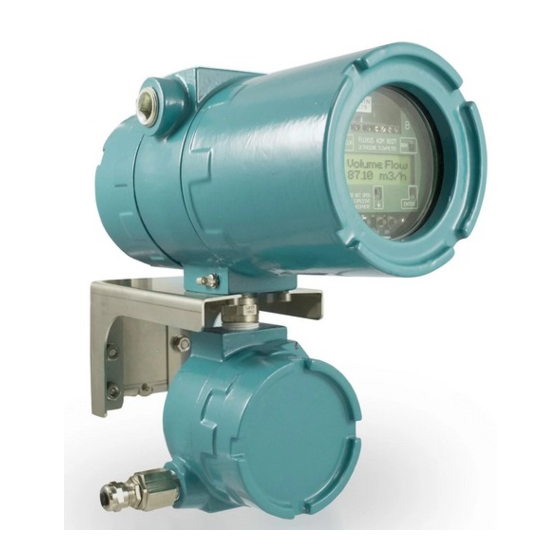
The transmitter consists of 1 housing. The command panel is on the front side of the housing. The keys are operated by a magnetic pen with the housing closed. The terminals for the connection of transducers, outputs and power supply are on the back side of the housing (see Fig. 4.2). Fig. 4.1: FLUXUS G800 Fig. 4.2: FLUXUS G801 UMFLUXUS_G8V4-6-1EN, 2018-10-10…
-
Page 18: Keyboard
FLUXUS G80x 4 Description of the Transmitter Keyboard The keyboard consists of 5 keys. Tab. 4.1: General functions ENTER confirmation of selection or entered value BRK + CLR + ENTER RESET: Press these three keys simultaneously to correct a malfunction. The reset has the same effect as restarting the transmitter.
-
Page 19: Selection Of The Measuring Point
5 Selection of the Measuring Point FLUXUS G80x Selection of the Measuring Point Attention! Observe the «Safety Instructions for the Use in Explosive Atmosphere» (see document SIFLUXUS). The correct selection of the measuring point is crucial for achieving reliable measurement results and a high measurement accuracy.
-
Page 20: Undisturbed Flow Profile
FLUXUS G80x 5 Selection of the Measuring Point Undisturbed Flow Profile Some flow elements (elbows, slide valves, valves, control valves, pumps, reducers, diffusers, etc.) distort the flow profile in their vicinity. The axisymmetrical flow profile needed for correct measurement is no longer given. A careful selection of the measuring point helps to reduce the impact of disturbance sources.
-
Page 21
5 Selection of the Measuring Point FLUXUS G80x Tab. 5.2: Recommended distance from disturbance sources; D – nominal pipe diameter at the measuring point, l – recommended distance disturbance source: T piece supply line: l ≥ 100 D return line: l ≥ 20 D disturbance source: diffuser supply line: l ≥… -
Page 22: Influence Of Noise
FLUXUS G80x 5 Selection of the Measuring Point Influence of Noise The ultrasonic waves do not only propagate in the fluid but also in the pipe wall (see Fig. 5.1). They are reflected at flang- ultrasonic waves in the fluid (measuring signal) ultrasonic waves in the pipe wall (pipe wall signal) Fig.
-
Page 23: Selection Of The Measuring Point Taking Into Account The Flow Profile And The Influence Of Noise
5 Selection of the Measuring Point FLUXUS G80x Tab. 5.3: Measuring points to be avoided Example: fluid: natural gas pipe material: stainless steel : 3000 m/s : 400 m/s number of sound paths: 2 = 7.5 D The range (7.5 ± 2) D is disadvantageous for the transducer installation. Selection of the Measuring Point Taking into Account the Flow Profile and the Influ- ence of Noise •…
-
Page 24
FLUXUS G80x 5 Selection of the Measuring Point Both demands cannot be observed always at the same time. In these cases, the measuring point has to be selected in such way that the influence of noise is min. and the measuring point is as far from the disturbances of the flow profile as possible. -
Page 25: Selection Of The Measurement Arrangement Taking Into Account The Measuring Range And The Measuring Conditions
5 Selection of the Measuring Point FLUXUS G80x Selection of the Measurement Arrangement Taking into Account the Measuring Range and the Measuring Conditions Diagonal arrangement with 1 beam Reflection arrangement with 1 beam • wider flow velocity and sound speed range compared to •…
-
Page 26: Selection Of The Sound Beam Plane Near An Elbow
FLUXUS G80x 5 Selection of the Measuring Point Selection of the Sound Beam Plane near an Elbow With vertical pipe orientation With horizontal pipe flow direction elbow plane elbow plane flow direction • The sound beam plane (see section 3.3.1) has an angle •…
-
Page 27: Installation Of Fluxus G800
6 Installation of FLUXUS G800 FLUXUS G80x Installation of FLUXUS G800 Attention! Observe the «Safety Instructions for the Use in Explosive Atmosphere» (see document SIFLUXUS). Location • Select the measuring point according to the recommendations in chapter 3 and 5.
-
Page 28
FLUXUS G80x 6 Installation of FLUXUS G800 power supply outputs equipotential bonding terminal upper housing equipotential bonding terminal, lower housing transducers measuring transducers measuring channel B channel A Fig. 6.2: Connections of the Transmitter N/L- L1/L+ N/L- FLUXUS G800, G800L, G800LP… -
Page 29: Connection Of The Transducers
6 Installation of FLUXUS G800 FLUXUS G80x Fig. 6.4: Terminal designation of the transmitter (transducers) Connection of the Transducers Note! If transducers are replaced or added, the sensor module also has to be replaced or added (see sec- tion 6.9).
-
Page 30
FLUXUS G80x 6 Installation of FLUXUS G800 Attention! For good high frequency shielding, it is important to ensure good electrical contact between the exter- nal shield and the cap nut (and the housing). • Fix the cable gland by screwing the cap nut onto the basic part (see Fig. 6.5). -
Page 31
6 Installation of FLUXUS G800 FLUXUS G80x extension cable transducer cable external shield, external shield, brushed back brushed back extension cable compression part cap nut basic part cable gland Fig. 6.7: Connection of the extension and transducer cable to the junction box JB01 •… -
Page 32
FLUXUS G80x 6 Installation of FLUXUS G800 For the terminal assignment of the transducer cable see Fig. 6.7 and Tab. 6.5. Tab. 6.3: Terminal assignment (transducer cable) terminal connection transducer (core) transducer (shield) transducer (shield) transducer (core) 6.5.2.2 Connection with potential separation If earthing on the same potential cannot be ensured e.g., in measurement arrangements with long extension cables, the… -
Page 33: Connection Of The Power Supply
6 Installation of FLUXUS G800 FLUXUS G80x • Insert the extension cable into the junction box. • Prepare the extension cable. • Cut the outer shield to length and brush it back. • Pull the extension cable back until the brushed back external shield is below the shield terminal (see Fig. 6.8). The ex- tension cable has to remain completely insulated up to the shield terminal.
-
Page 34: Connection Of The Outputs
FLUXUS G80x 6 Installation of FLUXUS G800 cap nut compression part basic part Fig. 6.9: Cable gland FLUXUS G800, G800L, G800LP, FLUXUS G800C24, LC24, G800 FLUXUS G800P (transmitter without frequency output): FLUXUS G800P (transmitter with frequency output): L1(+) N/L- N(-)
-
Page 35
6 Installation of FLUXUS G800 FLUXUS G80x Tab. 6.7: Circuits of the outputs output transmitter external circuit remark internal circuit connection active current current loop loop/HART < 500 Ω G800 I1/I2: 2/4 (+) G800L current during transmitter error: ≈ 0 mA… -
Page 36
FLUXUS G80x 6 Installation of FLUXUS G800 Tab. 6.7: Circuits of the outputs output transmitter external circuit remark internal circuit connection frequency output = 5…30 V (open collector) F1: 2 (+) [kΩ] = U [mA] G800P = 2…100 mA = 0.8 mA… -
Page 37
6 Installation of FLUXUS G800 FLUXUS G80x 6.7.1 Intrinsically Safe Current Output Ex ib The current output may be fed with max. 28.2 V DC/0.76 W. Tab. 7: Circuit of the current output Ex ib output transmitter external circuit remark… -
Page 38: Connection Of The Serial Interface
RS232 adapter cable Fig. 6.1: RS232 interface of FLUXUS G800 • Insert the RS232 adapter into the socket in such way that the colored lead of the cable is on the marked side of the socket.
-
Page 39: Installation Of Fluxus G801
7 Installation of FLUXUS G801 FLUXUS G80x Installation of FLUXUS G801 Attention! Observe the «Safety Instructions for the Use in Explosive Atmosphere» (see document SIFLUXUS). Location • Select the measuring point according to the recommendations in chapter 3 and 5. •…
-
Page 40
FLUXUS G80x 7 Installation of FLUXUS G801 equipotential bonding terminal transducer measuring channel A transducer measuring channel B outputs power supply Fig. 7.2: Connections of the Transmitter FLUXUS G801**-A10****-AA, G801**-A10****-AP: FLUXUS G801C24, G801**-A10****-FF: Fig. 7.3: Terminal designation of the transmitter UMFLUXUS_G8V4-6-1EN, 2018-10-10… -
Page 41: Connection Of The Transducers
7 Installation of FLUXUS G801 FLUXUS G80x Connection of the Transducers Note! If transducers are replaced or added, the sensor module also has to be replaced or added (see sec- tion 7.9). It is recommended to run the cables from the measuring point to the transmitter before connecting the transducers to avoid load on the connectors.
-
Page 42
FLUXUS G80x 7 Installation of FLUXUS G801 Tab. 7.1: Terminal assignment (extension cable) terminal connection white or marked cable (core) white or marked cable (shield) brown cable (shield) brown cable (core) 7.5.2 Connection of the Extension Cable to the Junction Box 7.5.2.1 Connection without potential separation (standard) The connection of the extension cable to the junction box without potential separation ensures that transducer, junction… -
Page 43
7 Installation of FLUXUS G801 FLUXUS G80x • Prepare the extension cable. • Cut the external shield and brush it back over the compression part. • Screw the gasket ring side of the basic part into the junction box. • Insert the extension cable into the junction box. Attention! For good high frequency shielding, it is important to ensure good electrical contact between the exter- nal shield and the cap nut (and the junction box). -
Page 44
FLUXUS G80x 7 Installation of FLUXUS G801 K L 2 K L 1 shield terminal transducer cable extension cable external shield, external brushed back shield extension cable compression part cap nut basic part cable gland Fig. 7.7: Connection of the extension and transducer cable to the junction box JB01 •… -
Page 45: Connection Of The Power Supply
7 Installation of FLUXUS G801 FLUXUS G80x For the terminal assignment of the transducer cable see Fig. 7.7 and Tab. 7.5. Tab. 7.5: Terminal assignment (transducer cable) terminal connection transducer (core) transducer (shield) transducer (shield) transducer (core) Connection of the Power Supply Attention! Observe the «Safety Instructions for the Use in Explosive Atmosphere»…
-
Page 46: Connection Of The Outputs
FLUXUS G80x 7 Installation of FLUXUS G801 Tab. 7.6: Connection of the power supply terminal connection terminal connection earth earth neutral + DC Phase 100…240 V AC — DC Connection of the Outputs Attention! Observe the «Safety Instructions for the Use in Explosive Atmosphere» (see document SIFLUXUS). Attention! The outputs can only be connected to a low voltage circuit (max.
-
Page 47
7 Installation of FLUXUS G801 FLUXUS G80x Tab. 7.7: Circuits of the outputs output transmitter external circuit remark internal circuit connection passive current current loop loop/HART = 4…26.4 V G801**-A10****-*P I1/I2: 1/3 (-) > 0.021 A [Ω] + 4 V example: = 12 V = 0…380 Ω… -
Page 48
FLUXUS G80x 7 Installation of FLUXUS G801 Tab. 7.7: Circuits of the outputs output transmitter external circuit remark internal circuit connection RS485 120 Ω 14 (A+) termination resistor G801**-A10****-*A G801**-A10****-*P 13 (B-) shield 15 The number, type and connections of the outputs are customized. is the sum of all ohmic resistances in the circuit (e.g., resistance of the conductors, resistance of the amperemeter/voltmeter). -
Page 49: Connection Of The Serial Interface
7 Installation of FLUXUS G801 FLUXUS G80x Connection of the Serial Interface Attention! Observe the «Safety Instructions for the Use in Explosive Atmosphere» (see document SIFLUXUS). The RS232 interface can only be connected outside of an explosive atmosphere because the housing has to be opened (see Fig.
-
Page 50: Sensor Module (Sensprom)
FLUXUS G80x 7 Installation of FLUXUS G801 Sensor Module (SENSPROM) Attention! Observe the «Safety Instructions for the Use in Explosive Atmosphere» (see document SIFLUXUS). The sensor module contains important transducer data for the operation of the transmitter with the transducers. It is con- nected to the connector strips above the display of the transmitter.
-
Page 51: Mounting Of The Transducers
8 Mounting of the Transducers FLUXUS G80x Mounting of the Transducers Preparation of the Pipe • The pipe has to be stable. It has to be able to withstand the pressure exerted by the transducer mounting fixture. • Install the damping mats (see chapter 9). •…
-
Page 52
FLUXUS G80x 8 Mounting of the Transducers Overview of the mounting steps • step 1 disassemble the transducer mounting fixture Variofix L • step 2 fix the clasps to the tension straps • step 3 fix one tension strap to the pipe •… -
Page 53
8 Mounting of the Transducers FLUXUS G80x 8.3.1 Disassembly of Variofix L • Disassemble the transducer mounting fixture Variofix L (see Fig. 8.5). cover screw rail tension strap clamp Fig. 8.5: Disassembly of Variofix L 8.3.2 Fixing the Clasps to the Tension Straps Select the installation instructions that correspond to the supplied clasp: Band clamp clasp The clasp is fixed to the tension strap (see Fig. -
Page 54
FLUXUS G80x 8 Mounting of the Transducers Fig. 8.8: Ratchet clasp with tension strap 8.3.3 Fixing the Tension Strap to the Pipe One tension strap is fixed to the pipe (see Fig. 8.9). The second tension strap is mounted later. metal spring tension strap clamp clasp… -
Page 55
8 Mounting of the Transducers FLUXUS G80x screw of screw of the clasp the clasp Fig. 8.12: Band clamp clasp with tension strap Fig. 8.13: Quick release clasp with tension strap • Place the tension strap around the pipe and insert it into the clasp (see Fig. 8.13). •… -
Page 56
FLUXUS G80x 8 Mounting of the Transducers screw of lever the clasp sense of rotation Fig. 8.16: Ratchet clasp with tension strap Attention! To release the screw and the tension strap, press the lever down (see Fig. 8.16). 8.3.4 Fixing the Rail to the Pipe •… -
Page 57
8 Mounting of the Transducers FLUXUS G80x metal spring tension strap 1 clasp Fig. 8.19: Rail on the pipe Quick release clasp • Insert the tension strap into tension strap clamp 1 and the metal spring (see Fig. 8.21 and Fig. 8.19). •… -
Page 58
FLUXUS G80x 8 Mounting of the Transducers metal spring tension strap Fig. 8.22: Tension strap with the metal spring and the tension strap clamp Fig. 8.23: Ratchet clasp with tension strap lever screw of the clasp sense of rota- Fig. 8.24: Ratchet clasp with tension strap Note! To release the screw and the tension strap, press the lever down (see Fig. -
Page 59
8 Mounting of the Transducers FLUXUS G80x 8.3.5 Installation of the transducers in Variofix L • Press the transducers firmly on the transducer clamping fixture in the covers until the transducers are firmly fixed (one transducer in each cover). The transducer cables show in opposite directions (see Fig. 8.26). cover transducer clamping fixture… -
Page 60: Installation With Variofix C
FLUXUS G80x 8 Mounting of the Transducers Installation with Variofix C When measuring in reflection arrangement, one transducer mounting fixture is mounted on the side of the pipe (see Fig. 8.29). When measuring in diagonal arrangement, two transducer mounting fixtures are mounted on the opposite sides of the pipe (see Fig.
-
Page 61
8 Mounting of the Transducers FLUXUS G80x 8.4.1 Disassembly of Variofix C • Disassemble the transducer mounting fixture Variofix C. In order to remove the cover from the rail, bend the outer sides of the cover outwards (see Fig. 8.32). In order to remove the spring clip from the rail, slide it over the indentation on the rail and lift it off (see Fig. -
Page 62
FLUXUS G80x 8 Mounting of the Transducers tension strap clamp Fig. 8.34: Tension strap with tension strap clamp tension strap clamp metal spring metal spring Fig. 8.35: Tension strap with the metal spring and the tension strap clamp • Position the metal spring (if mounted) and the tension strap clamp (see Fig. 8.36): –… -
Page 63
8 Mounting of the Transducers FLUXUS G80x Installation of the rail with the ratchet clasp • Cut the tension strap to length (pipe circumference + at least 120 mm). Note! The edge of the tension strap is very sharp, leading to risk of injury. Remove the burr of the sharp edge. •… -
Page 64
FLUXUS G80x 8 Mounting of the Transducers metal spring ratchet clasp tension strap clamp Fig. 8.40: Tension strap with the metal spring, the ratchet clasp and the tension strap clamp on the pipe Fig. 8.41: Ratchet clasp with tension strap screw of lever the clasp… -
Page 65
8 Mounting of the Transducers FLUXUS G80x 8.4.3 Installation of the Transducers in Variofix C • Put coupling foil (or some coupling compound for a short-term installation) on the contact surface of the transducers. The coupling foil can be fixed to the contact surface with a small amount of the coupling compound. Note! If coupling foil is used: If the signal is not sufficient for the measurement, use the coupling compound instead of the coupling foil. -
Page 66
FLUXUS G80x 8 Mounting of the Transducers The cover can be removed from the mounted transducer mounting fixture Variofix C as follows: • Use a lever tool to remove the cover. • Insert the lever tool in one of the four openings of the cover (see Fig. 8.47). •… -
Page 67: Damping Mats
9 Damping mats FLUXUS G80x Damping mats Before the transducer mounting fixture is mounted, damping mats are installed. • Ultrasonic waves do not only propagate in the fluid but also in the pipe wall. Transducer damping mats are installed to counteract the propagation of ultrasonic waves in the pipe wall.
-
Page 68
FLUXUS G80x 9 Damping mats • Determine the number and size of the damping mats that are to be installed: – For outer pipe diameters < 900 mm, see section 9.3.1. – For outer pipe diameters > 900 mm, see section 9.3.2. •… -
Page 69
9 Damping mats FLUXUS G80x • Depending on the transducer type, it can be necessary to install additional layers of damping mats (see Technical Spec- ification, annex Damping mats). Repeat the steps for the installation of the damping mat. • When mounting the transducer, make sure not to mount the transducers on the seams between the damping mats. If the transducers are mounted on the seams, there must be no gaps between the damping mats under the transducers, this means the damping mats must be installed edge to edge. -
Page 70
FLUXUS G80x 9 Damping mats Example: measurement in reflection arrangement 2 transducer mounting fixtures Variofix L M transducer width of the damping mat: 50 mm outer pipe diameter: 100 mm length of Variofix L: 310 mm reflection point: 1 calculation of the installation length (see Tab. 9.1): •… -
Page 71
9 Damping mats FLUXUS G80x 9.3.2 Outer pipe diameter > 900 mm For the calculation of the installation length of the transducer and pipe damping mats, see Tab. 9.2. Tab. 9.2: Installation length of the transducer and pipe damping mats Diagonal arrangement Reflection arrangement no reflection points… -
Page 72
FLUXUS G80x 9 Damping mats Example: measurement in diagonal arrangement 2 transducer mounting fixtures Variofix C G transducer width of the damping mat: 225 mm outer pipe diameter: 1200 mm width of Variofix C: 560 mm reflection points: 2 Calculation of the installation lengths (see Tab. 9.2): •… -
Page 73: Start-Up Of The Transmitter
Start-Up of the Transmitter 10.1 Switching on As soon as the transmitter is connected to the power supply, the serial number of the trans- FLEXIM FLUXUS mitter is displayed for a short time. G80X -XXXXXXXX It is not possible to enter any data while the serial number is displayed.
-
Page 74
FLUXUS G80x 10 Start-Up of the Transmitter 10.3.2 Program Branches • Program branch Parameter input of the pipe and fluid parameters • Program branch Measuring processing of the steps for the measurement • Program branch Output Options setting of the physical quantity, the unit of measurement and the parameters for the transmission of measured value •… -
Page 75: Hotcodes
10 Start-Up of the Transmitter FLUXUS G80x 10.3.3 Navigation If a vertical arrow ↕ is displayed, the menu item contains a scroll list. The current list item is displayed in the lower line. Press key to scroll and select a list item in the lower line. Press Parameter ↕…
-
Page 76: Language Selection
As soon as the measurement begins, all current measuring parameters will be stored in a non-volatile INIT-resistant EPROM. The measurement will be interrupted if the power supply fails. All input data remain saved. After the return of the power supply, the serial number is displayed for a few seconds. FLEXIM FLUXUS G80X -XXXXXXXX The interrupted measurement is continued.
-
Page 77: Basic Measurement
11 Basic Measurement FLUXUS G80x Basic Measurement Attention! Observe the «Safety Instructions for the Use in Explosive Atmosphere» (see document SIFLUXUS). The pipe and fluid parameters are entered for the selected measuring point (see chapter 5). The parameter ranges are limited by the technical characteristics of the transducers and the of transmitter.
-
Page 78: Input Of The Fluid Parameters
FLUXUS G80x 11 Basic Measurement When the pipe material has been selected, the corresponding sound speed is set automatically. If Other Material is selected, the sound speed has to be entered. Enter the sound speed of the pipe material. Press ENTER. c-Material 3230.0 Note!
-
Page 79
11 Basic Measurement FLUXUS G80x If Other Medium is selected or no data set for the selected fluid is stored in the transmitter, the fluid parameters have to be entered first: • average sound speed of the fluid • range around the average sound speed of the fluid •… -
Page 80: Other Parameters
Press ENTER. Note! If standard transducer parameters are used, FLEXIM cannot guarantee for the precision of the mea- sured values. A measurement might even be impossible. If Special Version is selected, enter the 6 transducer parameters specified by the Transd.
-
Page 81: Defining The Number Of Sound Paths
11 Basic Measurement FLUXUS G80x If the data logger or the serial interface is activated, the measuring point number has to be entered: Enter the measuring point number. Press ENTER. A:Meas.Point No.: If arrows are displayed in the lower line on the right, ASCII text can be entered. If no arrows xxx (↑↓←…
-
Page 82
FLUXUS G80x 11 Basic Measurement 11.6.2 Consistency Check If a wide range for the sound speed has been entered in the program branch Parameter or the exact parameters of the fluid are unknown, a consistency check is recommended. The transducer distance can be displayed during the measurement by scrolling the key The optimum transducer distance is displayed in brackets (here: 50.0 mm) in the upper L=(50.0) 54.0 mm line, followed by the entered transducer distance (here: 54.0 mm). -
Page 83: Start Of The Measurement
11 Basic Measurement FLUXUS G80x 11.7 Start of the Measurement The measured values are displayed in the lower line. Press ENTER to return to the fine ad- A:act. Volume flow justment of the transducer distance (see section 11.6.1). 31.82 m3/h If the standard volumetric flow rate is selected as physical quantity during the gas measurement, the operating volumetric flow rate can also be displayed.
-
Page 84: Displaying The Measured Values
FLUXUS G80x 12 Displaying the Measured Values Displaying the Measured Values The physical quantity is set in the program branch Output Options (see section 12.1). During the measurement, the designation of the physical quantity is displayed in the upper line, the measured value in the lower line.
-
Page 85: Toggling Between The Channels
12 Displaying the Measured Values FLUXUS G80x The following list items are available: list item display of the operating volumetric flow display of the standard volumetric rate flow rate without prefix, e.g., m³/h without prefix, e.g., m³/h (none) without prefix, e.g., m³/h with prefix N, e.g., Nm³/h ’…
-
Page 86: Adjustment Of The Display
FLUXUS G80x 12 Displaying the Measured Values 12.3 Adjustment of the Display During the measurement, the display can be adapted as to display two measured values simultaneously (one in each line of the display). This does not affect totalizing, transmission of the measured values, etc. The following information can be displayed in the upper line: display explanation…
-
Page 87: Transducer Distance
12 Displaying the Measured Values FLUXUS G80x value explanation signal amplitude < 5 % … … ≥ 90 % Values ≥ 3 are sufficient for the measurement. signal quality < 5 % … … ≥ 90 % sound speed comparison of the measured and the expected sound speed of the fluid. The expected sound speed is calculated on the basis of the fluid parameters (fluid selected in the program branch Parameter, tem- perature dependence, pressure dependence).
-
Page 88: Advanced Measuring Functions
FLUXUS G80x 13 Advanced Measuring Functions Advanced Measuring Functions 13.1 Command Execution during Measurement Commands that can be executed during a measurement are shown in the upper line. A command begins with →. If pro- grammed, a program code has to be entered (see section 13.11). Press key until the command is displayed.
-
Page 89
13 Advanced Measuring Functions FLUXUS G80x Press key to scroll through the upper line and display the totalizers. A:act. Volume flow 54.5 54.5 m3/h m3/h The totalizer value will be displayed in the upper line (here: the volume which has passed 32.5 through the pipe at the measuring point in positive flow direction since the activation of the 54.5… -
Page 90: Upper Limit Of The Flow Velocity
FLUXUS G80x 13 Advanced Measuring Functions 13.4 Upper Limit of the Flow Velocity Single outliers caused by heavily disturbed surroundings can appear among the measured values of the flow velocity. If the outliers are not ignored, they will affect all derived physical quantities, which will then be unsuitable for the integration (e.g., pulse outputs).
-
Page 91: Uncorrected Flow Velocity
13 Advanced Measuring Functions FLUXUS G80x 13.6 Uncorrected Flow Velocity For special applications, the uncorrected flow velocity might be of interest. The profile correction for the flow velocity is activated in Special Funct.SYSTEM settingsMeasuringFlow Velocity. Select normal to display and output the flow velocity with profile correction. Flow Velocity Select uncorr.
-
Page 92: Calculation Channels
FLUXUS G80x 13 Advanced Measuring Functions 13.7.3 Activation/Deactivation of the FastFood Mode If the FastFood mode is enabled and a measurement is started, the normal measuring mode will still be running (i.e. multi- channel measurement with permanent adaptation to the measuring conditions). If the data logger is activated, the mea- sured values will not be stored.
-
Page 93
13 Advanced Measuring Functions FLUXUS G80x Three scroll lists are displayed in the upper line: >CH1< funct ch2↕ • selection of the first measuring channel (ch1) • selection of the calculation function (funct) • selection of the second measuring channel (ch2) Select a scroll list with key The list items are displayed in the lower line. -
Page 94: Change Of The Limit For The Inner Pipe Diameter
FLUXUS G80x 13 Advanced Measuring Functions Select the unit of measurement. Press ENTER. Mass in: ↕ kg/h Two cut-off flow values for each calculation channel can be defined. They are defined in the unit of measurement of the physical quantity selected for the calculation channel. All positive calculated values that are lower than the limit will be set to 0.
-
Page 95: Diagnosis With The Snap Function
13 Advanced Measuring Functions FLUXUS G80x 13.10 Diagnosis with the Snap Function With the aid of the snap function it is possible to store measuring parameters which are useful for the evaluation of mea- suring results or for diagnostic purposes. The snap function is activated in Special Funct.SYSTEM settingsSignal snapDSP-SignalSnap.
-
Page 96
FLUXUS G80x 13 Advanced Measuring Functions 13.11.2 Intervention in the Measurement If a program code is active, the message PROGRAM CODE ACTIVE will be displayed for a few seconds when a key is pressed. The input of a program code is interrupted by pressing key CLR. If key BRK is pressed: To stop an ongoing measurement, the complete program code has to be entered (= break INPUT BREAK_CODE… -
Page 97: Data Logger And Transmission Of Data
The transmitter has a data logger in which the measured values are stored during the measurement (see section 14.1). Additionally measured values can be transmitted to a PC via the serial interface (see section14.2). For the connection of the serial interface to the transmitter see section 6.8 (FLUXUS G800) or section 7.8 (FLUXUS G801). 14.1…
-
Page 98
FLUXUS G80x 14 Data Logger and Transmission of Data 14.1.3 Settings for the Data Logger Select Special Funct.SYSTEM settingsStoring. It contains the following menu items: • start of storing • ringbuffer • storage mode • storing of the totalizers • storing of the signal amplitude •… -
Page 99
14 Data Logger and Transmission of Data FLUXUS G80x Storing of the Signal Amplitude If on is selected and the data logger is activated, the amplitude of the measured signal will Store Amplitude be stored together with the measured values. Press ENTER. >ON<… -
Page 100: Transmission Of Data
FLUXUS G80x 14 Data Logger and Transmission of Data The type and the serial number of the transmitter is displayed in the upper line. G80X -XXXXXXXX The available data logger memory will be displayed in the lower line (here: 18 327 addition- Free: 18327 al measured values can be stored).
-
Page 101
14 Data Logger and Transmission of Data FLUXUS G80x Select the decimal marker to be used for floating-point numbers (point or comma). Press SER:decimalpoint ENTER. ’.’ >’,’< This setting depends on the setting of the operating system of the PC. Select the character to be used to separate columns (semicolon or tabulator). -
Page 102
FLUXUS G80x 14 Data Logger and Transmission of Data 14.2.5 Online Transmission of Data to a Terminal Program • Start the terminal program. • Enter the transmission parameters into the terminal program (see section 14.2.4). The transmission parameters of the terminal program and the transmitter have to be identical. -
Page 103
FLUXUS G80x 14.2.7 Offline Transmission of Data with the Program FluxData The measurement data in the data logger are transmitted to a PC via the serial interface RS232 with the FLEXIM program FluxData. Settings in the Program Start the program FluxData V3.0 or higher on the PC. -
Page 104
FLUXUS G80x 14 Data Logger and Transmission of Data Stop the Transmission of Data Select the menu: File > Save. Select the series of measured values to be stored. Click OK. Select the path on which the data should be stored and enter the file name. -
Page 105
14 Data Logger and Transmission of Data FLUXUS G80x The line DATA is transmitted next followed once by the column titles (see Tab. 14.3) for the corresponding channel. The measured values are transmitted afterwards. Example: DATA A: *MEASURE; Q_POS; Q_NEG; B: *MEASURE;… -
Page 106: Libraries
FLUXUS G80x 15 Libraries Libraries The internal material database of the transmitter contains parameters for pipe and lining materials as well as for fluids. It can be extended with user defined materials or fluids. User defined materials and fluids will always be displayed in the scroll lists of the program branch Parameter.
-
Page 107: Input Of Material/Fluid Parameters Without The Extended Library
15 Libraries FLUXUS G80x 15.1.1 Data Retention during Coefficient Memory Partitioning When the coefficient memory is repartitioned, max. 8 data sets of each type can be retained. Example The number of user defined materials is reduced from 5 to 3. The data sets #01 to #03 are retained. The data sets #04 and #05 are deleted.
-
Page 108: Extended Library
FLUXUS G80x 15 Libraries Select auto or user. Press ENTER. c-Medium range auto: The area around the average sound speed is defined by the transmitter. auto >USER< user: The area around the average sound speed has to be entered. Enter the range around the average sound speed of the fluid. Press ENTER. c-Medium=400m/s This display will only be indicated if user is selected.
-
Page 109
If, however, the process conditions fluctuate strongly and the fluid parameters depend strongly on the temperature (e.g., viscosity of hydraulic oil), polynomials or customized interpolation functions should be used. Contact FLEXIM to find the best solution for the measuring task. -
Page 110: Deleting A User Defined Material/Fluids
FLUXUS G80x 15 Libraries Material Parameter Enter the material’s: • transversal sound speed • longitudinal sound speed 1…5 values depending on the selected function have to be entered. Press ENTER after each input. If an already defined material is edited, for each parameter there will be a request whether it is to be edited. Select yes or no.
-
Page 111: Arrangement Of The Material/Fluid Scroll List
15 Libraries FLUXUS G80x 15.5 Arrangement of the Material/Fluid Scroll List The materials and fluids to be displayed in the program branch Parameter are arranged in the material scroll list or in the fluid scroll list. Note! User defined materials/fluids will always be displayed in the scroll lists of the program branch Pa- rameter.
-
Page 112
FLUXUS G80x 15 Libraries 15.5.3 Adding all Materials/Fluids to the Scroll List Select Add all to add all materials/fluids of the database to the current scroll list. Press Material list ↕ ENTER. >Add all 15.5.4 Removing a Material/Fluid from the Scroll List Select Remove Material or Remove Medium to remove a material/fluid from the scroll Material list ↕… -
Page 113: Settings
16 Settings FLUXUS G80x Settings 16.1 Time and Date The transmitter has a battery-powered clock. Measured values are automatically stored with the date and time. 16.1.1 Time Select Special Funct.SYSTEM settingsSet Clock. SYSTEM settings↕ Set Clock Press ENTER. The current time is displayed. Select ok to confirm the time or new to set the time. Press TIME 11:00 ENTER.
-
Page 114
FLUXUS G80x 16 Settings Enter the pipe circumference. The limits for the pipe circumference are calculated on the Pipe Circumfer. basis of the limits for the outer pipe diameter. During the next scroll through the program branch Parameter, the outer pipe diameter Outer Diameter that corresponds to the entered pipe circumference will be displayed. -
Page 115
16 Settings FLUXUS G80x 16.2.6 Alarm State Indication Select on to display the alarm state during the measurement. SHOW RELAIS STAT For further information on the alarm outputs see section 18.6. >ON< 16.2.7 Units of Measurement It is possible to set the units of measurement for the length, temperature, pressure, density and kinematic viscosity and sound speed: Select mm or inch as the unit of measurement for the length. -
Page 116: Measurement Settings
FLUXUS G80x 16 Settings 16.3 Measurement Settings Select Special Funct.SYSTEM settingsMeasuring. Press ENTER. SYSTEM settings↕ Measuring Note! The settings will be stored at the end of the dialog. If the menu item is quit by pressing key BRK, the changes will not be stored. Select on to activate the gas measurement, off to deactivate it.
-
Page 117: Settings Of The Standard Conditions For The Gas Measurement
16 Settings FLUXUS G80x 16.4 Settings of the Standard Conditions for the Gas Measurement Select Special Funct.SYSTEM settingsGas-Measuring. Press ENTER. SYSTEM settings↕ This display will only be indicated if the gas measuring has been activated in Special Gas-Measuring Funct.SYSTEM settingsMeasuring. Enter the pressure for the local standard conditions.
-
Page 118: Superuser Mode
FLUXUS G80x 17 SuperUser Mode SuperUser Mode The SuperUser mode offers the possibility of an advanced analysis of the signal and the measured values as well as the definition of additional parameters adapted to the measuring point, in order to achieve better measuring values or during experimental work.
-
Page 119
17 SuperUser Mode FLUXUS G80x 17.3.1 Profile Bounds Select user if the profile bounds are to be defined. If factory is selected, the default pro- A:Profile bounds file bounds will be used and the menu item Calibration will be displayed (see section factory >USER<… -
Page 120: Limit Of The Signal Amplification
FLUXUS G80x 17 SuperUser Mode Example 2: Slope: -1.0 Offset: 0.0 Only the sign of the measured values is changed. Note! The correction data will only be stored when a measurement is started. If the transmitter is switched off without starting a measurement, the entered correction data will be lost. Attention! The correction of the flow velocity is still active after the deactivation of the SuperUser mode.
-
Page 121: Detection Of Long Measurement Failures
17 SuperUser Mode FLUXUS G80x 17.6 Detection of Long Measurement Failures If there are no valid measured value during a long time interval, new increments of the totalizers will be ignored. The val- ues of the totalizers remain unchanged. In the SuperUser mode, it is possible to set the time interval. Select Special Funct.SYSTEM settingsMeasur- ingMiscellaneous.
-
Page 122: Display Of The Totalizer Sum
FLUXUS G80x 17 SuperUser Mode 17.9 Display of the Totalizer Sum The sum of the totalizers for the two flow directions can be displayed in the upper line during the measurement. Select Special Funct.SYSTEM settingsMeasuringMiscellaneous. Press ENTER until the menu item Show ΣQ is displayed.
-
Page 123: Outputs
18 Outputs FLUXUS G80x Outputs If the transmitter is equipped with outputs, they have to be installed and activated before they can be used: • assign a measuring channel (source channel) to the output (if the transmitter has more than one measuring channel) •…
-
Page 124
FLUXUS G80x 18 Outputs Tab. 18.1: Configuration of the outputs source item list item output sound speed of the fluid Miscellaneous c-Medium concentration of the fluid Concentration signal amplitude of a measuring channel Signal ratio useful signal to correlated disturbance signal SCNR standard deviation of the signal amplitude VariAmp… -
Page 125
18 Outputs FLUXUS G80x Example: source item: volumetric flow rate output: current output output range: 4…20 mA error value delay t (see section 18.2): > 0 The volumetric flow rate cannot be measured during the time interval t …t (see Fig. 18.1). The error value will be transmitted. -
Page 126: Error Value Delay
FLUXUS G80x 18 Outputs Select a list item for the error output. Press ENTER. Error-value ↕ Minimum (4.0mA) If Other value is selected, enter an error value. It has to be within the limits of the output. Error-value Press ENTER. Note! The settings will be stored at the end of the dialog.
-
Page 127: Activation Of An Analog Output
18 Outputs FLUXUS G80x 18.3 Activation of an Analog Output Note! An output can only be activated in the program branch Output Options if it has previously been in- stalled. In the program branch Output Options, select the channel for which an output is to be Output Options ↕…
-
Page 128: Configuration Of A Frequency Output As A Pulse Output
FLUXUS G80x 18 Outputs 18.4 Configuration of a Frequency Output as a Pulse Output A A frequency output sends a signal with a frequency that depends on the volumetric flow rate. The frequency output can be configured in such way that the source item can be totalized by using each period of the output signal as the increment. 18.4.1 Installation of a Frequency Output (optional) Select Frequency F1 in Special Funct.SYSTEM settingsProc.
-
Page 129: Activation Of A Binary Output As An Alarm Output
18 Outputs FLUXUS G80x Select yes to activate the output. Press ENTER. Pulse Output B1: no >YES< This error message will be displayed if the flow velocity is selected as the physical quantity. Pulse Output The use of the pulse output is not possible in this case because integrating the flow velocity NO COUNTING does not result in a reasonable value.
-
Page 130
FLUXUS G80x 18 Outputs Tab. 18.4: Alarm properties alarm property setting description The alarm will switch if the measured value exceeds the upper func (switching condition) limit. The alarm will switch if the measured value falls below the low- er limit. The alarm will switch if the flow direction changes (sign change +→- -→+ of measured value). -
Page 131: Behavior Of The Alarm Outputs
18 Outputs FLUXUS G80x Example 2: Low Limit: -10 m³/h volumetric flow rate = -11 m³/h the measured value is below the limit, the alarm switches volumetric flow rate = -9.9 m³/h the measured value is not below the limit, the alarm does not switch If the switching condition QUANT.
-
Page 132
FLUXUS G80x 18 Outputs 18.7.2 Reset and Initialization of the Alarms After an initialization of the transmitter all alarm outputs will be configured as follows: Tab. 18.5: Alarm state after an initialization func NON-HOLD mode NO Cont. Limit 0.00 Press key CLR three times during the measurement to set all alarm outputs to the idle state. Alarm outputs whose switch- ing condition is still met will be activated again after 1 s. -
Page 133: Deactivation Of The Outputs
18 Outputs FLUXUS G80x 18.7.5 Alarm State Indication Note! There is no visual or acoustic indication of alarm output switching. The alarm state can be displayed after the configuration of the alarm outputs and during the measurement. This function is activated in Special Funct.SYSTEM settingsDialogs/Menus.
-
Page 134: Troubleshooting
A program code has been defined. Press key CLR and enter the program code. The backlight of the display does not work, but all other functions are available The backlight is defective. This problem does not affect the other functions of the display. Send the transmitter to FLEXIM for repair.
-
Page 135: Selection Of The Measuring Point
• If no exclamation mark! is displayed, a measurement at the selected measuring point is not possible. Loss of signal during the measurement • If the pipe had been pressureless: Was there no measuring signal afterwards? Contact FLEXIM. • Wait briefly until acoustic contact is reestablished. The measurement can be interrupted by a temporarily higher propor- tion of liquid and solids in the fluid.
-
Page 136: Large Deviations Of The Measured Values
FLUXUS G80x 19 Troubleshooting 19.5 Large Deviations of the Measured Values The entered sound speed of the fluid is wrong A wrong sound speed can result in the ultrasonic signal that is reflected directly on the pipe wall being mistaken for the measuring signal that has passed through the fluid.
-
Page 137: A Menu Structure
A Menu Structure FLUXUS G80x Menu Structure INIT-resis- tant Program branch Parameter main menu: selection of the program branch Parameter >PAR< mea opt sf Parameter selection of a measuring channel (A, B) or of a calculation channel (Y, Z) Parameter ↕…
-
Page 138
FLUXUS G80x A Menu Structure INIT-resis- tant selection of the sound speed range c-Medium range auto: The area around the average sound speed is defined by the transmit- auto >USER< ter. user: The area around the average sound speed has to be entered. input of the area around the average sound speed of the fluid c-Medium=400m/s This display will only be indicated if user is selected. -
Page 139
A Menu Structure FLUXUS G80x INIT-resis- tant activation of the channels CHANN:>A< B Y Z This display will not be indicated if the transmitter has only one measuring MEASUR — . channel. input of the measuring point number A:Meas.Point No.: This display will only be indicated if Output OptionsStore Meas.Data xxx (↑↓←… -
Page 140
FLUXUS G80x A Menu Structure INIT-resis- tant Current loop activation of a current output Current Loop This display will only be indicated if the current output has been installed in I1: no >YES< Special Funct.SYSTEM settingsProc. outputs. selection whether the sign of the measured values is to be considered for the Meas.Values output >ABSOLUT<… -
Page 141
A Menu Structure FLUXUS G80x INIT-resis- tant input of the limit for the flow totalizer of the physical quantity to be monitored Quantity Limit: This display will only be indicated if Alarm Output is activated and QUANT. 1.00 is selected as the switching condition. input of the hysteresis for the lower or upper limit R1 Hysterese: This display will only be indicated if Alarm Output is activated and MIN or… -
Page 142
FLUXUS G80x A Menu Structure INIT-resis- tant the coefficient memory is being partitioned FORMATTING … ■■■■■■ SYSTEM settingsLibrariesExtended Library selection of the displays for the activation of the extended library Libraries ↕ Extended Library Activation of the Extended Library Extended Library >ON<… -
Page 143
A Menu Structure FLUXUS G80x INIT-resis- tant selection if lb/ft³ is to be used as unit of measurement for the density Density [lb/ft3] >YES< selection of the unit of measurement for the density Density unit This display will only be indicated if lb/ft³ has not been selected as the unit of g/cm3 >kg/m3<… -
Page 144
FLUXUS G80x A Menu Structure INIT-resis- tant input of the fixed upper limit of the sound speed A: Bad soundspeed range: 0…3 000 m/s thresh. 2007 m/s 0: the default limit of 1 848 m/s will be used This display will only be indicated if the SuperUser mode is activated. Input of the offset. -
Page 145
A Menu Structure FLUXUS G80x INIT-resis- tant Input of the min. Reynolds number at which the flow is turbulent. Turbulent flow range: 0…25 500 (rounded to hundreds) if R*> 0: the default limit of 3 000 will be used This display will only be indicated if the SuperUser mode is activated and Profile bounds = user is selected. -
Page 146
FLUXUS G80x A Menu Structure INIT-resis- tant setting of the storing behavior of the totalizers Quantity Storage • one: the value of the totalizer that is currently displayed will be stored >BOTH< • both: one value for each flow direction will be stored activation of the signal amplitude storing Store Amplitude The value will only be stored if the data logger is activated. -
Page 147
A Menu Structure FLUXUS G80x INIT-resis- tant setting of the display contrast SETUP DISPLAY ← CONTRAST → confirmation that a HotCode has to be entered Input a HOTCODE >YES< input of a HotCode Please input a HOTCODE: 000000 Instrum. Inform. selection of the displays for information about the transmitter Special Funct. -
Page 148
FLUXUS G80x A Menu Structure INIT-resis- tant Install Material with Special Funct.SYSTEM settings LibrariesExtended Library = off selection whether a user defined material is to be edited or deleted Install Material >EDIT< delete selection of a user defined material USER Material ↕… -
Page 149
A Menu Structure FLUXUS G80x INIT-resis- tant Install Medium with Special Funct.SYSTEM settings LibrariesExtended Library = off selection whether a user defined fluid is to be edited or deleted Install Medium >EDIT< delete selection of a user defined fluid USER Medium ↕… -
Page 150
FLUXUS G80x A Menu Structure INIT-resis- tant confirmation that the changes are to be saved Save changes This display will only be indicated if a new fluid has been entered or the pa- >YES< rameters of an existing fluid have been changed. input of the compressibility coefficient of the gas GASFACTOR input of the compressibility coefficient of the gas… -
Page 151: B Units Of Measurement
B Units of Measurement FLUXUS G80x Units of Measurement Length/roughness Temperature unit of measurement description unit of measurement description millimeter degree Celsius °C inch degree Fahrenheit inch °F Pressure unit of measurement description bar (absolute) bar(a) bar (relative) bar(g) pound per square inch (absolute) psi(a) pound per square inch (relative) psi(g)
-
Page 152
FLUXUS G80x B Units of Measurement Standard/operational volumetric flow rate Volume (totalized) unit of measurement description unit of measurement cubic meter per day m³/d m³ cubic meter per hour m³/h m³ cubic meter per minute m³/min m³ cubic meter per second m³/s m³… -
Page 153
B Units of Measurement FLUXUS G80x Mass flow rate Mass (totalized) unit of measurement description unit of measurement metric ton per hour metric ton per day kilogram per hour kg/h kilogram per minute kg/min kilogram per second kg/s gram per second pound per day lb/d pound per hour… -
Page 154
FLUXUS G80x B Units of Measurement Flow Nomogram (Metrical) volumetric flow rate volumetric flow rate V o l u m e n f l u s s V o l u m e n f l u s s 1 0 0 1 0 0 1 0 0 1 0 0… -
Page 155
B Units of Measurement FLUXUS G80x Flow Nomogram (imperial) volumetric flow rate volumetric flow rate V o l u m e n f l u s s V o l u m e n f l u s s 1 0 0 1 0 0 1 0 0 1 0 0… -
Page 156: C Reference
The following tables provide assistance for the user. The accuracy of the data depends on the composition, temperature and processing of the material. FLEXIM does not assume liability for any inaccuracies. Sound Speed of Selected Pipe and Lining Materials at 20 °C The values of some of these materials are stored in the internal database of the transmitter.
-
Page 157
C Reference FLUXUS G80x Typical Roughnesses of Pipes The values are based on experience and measurements. Material Absolute roughness [mm] drawn pipes of non-ferrous metal, glass, plastics and light 0…0.0015 metal drawn steel pipes 0.01…0.05 fine-planed, polished surface max. 0.01 planed surface 0.01…0.04 rough-planed surface… -
Page 158
FLUXUS G80x C Reference Fluid (display) Explanation Sound speed Kinematic viscosity Density [m/s] [mm²/s] [g/cm³] ISO VG 22 1 487 50.2 0.8690 ISO VG 22 ISO VG 220 1 487 811.1 0.8690 ISO VG 220 ISO VG 32 1 487 78.0 0.8690 ISO VG 32… -
Page 159
C Reference FLUXUS G80x Properties of Methane Fluid Fluid Density Sound Kinematic Compressibility temperature pressure [kg/m³] speed viscosity coefficient [°C] [bar] [m/s] [mm²/s] (AGA8-DC92) 31,177 415.43 0.358693909 0.9062727 29,683 425.18 0.38628171 0.9182674 28,354 434.39 0.414403611 0.928556 27,159 443.13 0.44309437 0.9374469 26,076 451.46 0.472426753… -
Page 160: D Maintenance
Examination of the O-ring Attention! O-rings on increased safety housings may only be replaced by trained FLEXIM personnel. • Check the O-ring when opening the flameproof enclosure housing (FLUXUS G800, see Fig. D.1, FLUXUS G801, see Fig. D.2). Flameproof enclosure •…
-
Page 161
D Maintenance FLUXUS G80x Tab. D.1 transmitter O-ring item number FLUXUS G800, upper housing gasket Adalet 120 mm 990735-1 FLUXUS G800 lower housing gasket Adalet 95 mm 990735-2 FLUXUS G801 O-ring-125×2,5 on request UMFLUXUS_G8V4-6-1EN, 2018-10-10…
FLUXUS® G800 (G8027) и G801 (G8127) — это серия взрывозащищенных ультразвуковых расходомеров с накладными датчиками для стационарной установки на опасных производствах во взрывоопасных Зонах 1 и 2, а также для тяжелых условий эксплуатации (на морских буровых платформах).
Особенности
• Диапазон измерений скорости потока 0,01…35 м/с
• Время-импульсный корреляционный метод измерений
• Погрешность измерений ±2 % (опция ±1 %)
• Рабочие среды: природный газ, водород, кислород, аргон, гелий, природный газ и другие
• Трубопровод: в зависимости от типа газа и материала трубопровода требуется наличие минимального давления
• Межповерочный интервал 4 года
Область применения
• Измерение потока при закачке и отборе природного газа на станциях ПХГ
• Измерение расхода на трубопроводах природного газа
• Измерение дебита газовых скважин
• Измерение дебита на газовых платформах
• Измерение расхода закачиваемого газа при добыче нефти
Основные технические характеристики
| Масса | G800: 2,8 кг, G801: 8,5 кг |
| Материал корпуса |
G800: специальное покрытие для морских условий G801: нерж. сталь |
| Электропитание | 100…240 В 50/60 Гц, 12…36 В пост. тока |
| Рабочая температура: |
блок электроники -40 °С…+60 °С накладные датчики -55 °С…+150 °С (в зависимости от типа) |
| Измерительные каналы | 1 канал или 2 канала |
| Измерительные функции | счетчик объема/массы, расход объема/массы, скорость потока |
| Степень пылевлагозащиты электронного блока | G800: IP66, G810: IP67 |
| Степень пылевлагозащиты накладных датчиков | IP67 (опция IP68) |
| Варианты комплектации и наличие аналоговых выходов |
базовые выходы: 1× токовый, 2× реле, опции: выходы: 0/4…20 мА, реле |
| Интерфейс связи | Modbus RTU (по интерфейсу RS485) (опция), HART (опция) |
| Маркировка взрывозащиты | 2ExdeICIT6…T3, взрывоопасная зона 1 или 2 |
| Материал корпуса |
G800: специальное покрытие для морских условий G801: нерж. сталь 316/316L |
| Диаметр трубы | от 7 мм до 1600 мм |
| Регистрационный номер Госреестра СИ РФ | 56831-14, межповерочный интервал 4 года |
Комплект поставки
• Блок электроники G800 / G801
• Выбранные накладные датчики
• Контактные акустические материалы: паста/фольга/изоляционные маты
• Крепления датчиков на трубопровод
• Руководство по эксплуатации на русском языке
• Копии сертификатов, свидетельств
• Копии разрешительных документов

|
Скачать отзыв от ООО «НОВАТЕК-ЮРХАРОВНЕФТЕГАЗ» о расходомере FLUXUS |
Note for Owners:
Guidesimo.com webproject is not a service center of Flexim trademark and does not carries out works for diagnosis and repair of faulty Flexim FLUXUS G800 equipment. For quality services, please contact an official service center of Flexim company. On our website you can read and download documentation for your Flexim FLUXUS G800 device for free and familiarize yourself with the technical specifications of device.
-
Eastron SDM630MV-2L
EASTRON SDM630MV-2L Dual Load User ManualAddress: No.1369 Chengnan Road, Jiaxing, Zhejiang, 314001, China.Tel: 0086-573-83698881/83698882 Fax: 0086-573-83698883 Web: www.eastron.com.cnSDM630MV-2LDual load 3 Phase Wiring Smart Energy Meter Dual load split load measuring Measures kWh, kVarh, kW, kVar, KVA, P,F, PF, Hz, dmd, V, A,THD, etc. Bi-directional measurement IMP & EXP CT / PT …
SDM630MV-2L Measuring Instruments, 20
-
Macnaught M1 SERIES
PLEASE READ THIS INFORMATIONCAREFULLY BEFORE USE!Before use, confirm the fluid to be usedis compatible with the meter. Refer toIndustry fluid compatibility charts orconsult your local representative foradvice.To prevent damage from dirt or foreignmatter it is recommended that a Y orbasket type 200 mesh strainer beinstalled as close as possible to the inletside of the meter. Contact your localrepr …
M1 SERIES Measuring Instruments, 4
-
BGS technic DM1100
BGS technic KGBandwirkerstr. 342929 WermelskirchenTel.: 02196 720480Fax.: 02196 [email protected]© BGS technic KG, Vervielfältigung und Weiterverwendung verbotenArt. 2191 Feuchtigkeitsmesser TECHNISCHE DATEN Spannungsversorgung: 4 x 1,5 V LR44 Messbereich: Holzfeuchte: 6 bis 42% Materialfeuchte: 0,2 bis 2% Temperatur: 0 bis 40°C (32 bis 99°F) Auflösung Hol …
DM1100 Measuring Instruments, 17
-
Agilent Technologies 1670G Series
User’s GuideAgilent Technologies 1670G Series Logic AnalyzersPublication Number 01670-97014January 2000For Safety information, Warranties, and Regulatory information, see the pages behind the index.©Copyright Agilent Technologies 1994-2000 All Rights ReservedAdvanced Test Equipment Rentalswww.atecorp.com 800-404-ATEC (2832)®Established 1981 …
1670G Series Measuring Instruments, 632
-
CAME-TV CAME-ASTRAL
123456789111213101414ABCDok15CAME-TV Wireless Follow Focus System-V1.21One: Brief Introduction:CAME-TV Came-Astral wireless follow focus is a professional follow focus system designed for industryprofessionals. It features a reliable control of focus, iris, zoom, and it comes with a remote controller & motor.The controller features a control knob and a quick focus button to configure the OLED …
CAME-ASTRAL Measuring Instruments, 5
-
Nibe EME 10
LEKEME 10SEInstallatörshandbokMätningskit för solgenererad elGBInstaller manualMeasurement kit for solar generated electricityDEInstallateurhandbuchMessausrüstung für SolarstromFIAsentajan kasikirjaMittaussarja aurinkosähkölleNOInstallatørhåndbokMålesett for solgenerert strømIHB 1616-2331739 …
EME 10 Measuring Instruments, 24
-
Hioki 3274
EN3275CLAMP ON PROBE3274Instruction ManualMay 2015 Revised edition 5 3275A981-05 15-05H99 Washington Street Melrose, MA 02176 Phone 781-665-1400Toll Free 1-800-517-8431Visit us at www.TestEquipmentDepot.com …
3274 Measuring Instruments, 30
-
Keller-druck ECO1
Bedienungsanleitung ECO1 � …
ECO1 Measuring Instruments, 6
-
GF 2751-7
GF 2751-7 pH ElectronicsEnglishThe 2751-7 pH Smart Sensor Electronics processes analog signals from a pH electrode and transmits digital data via a three wire cable to the 9950-X Chlorine Controller. The DryLoc® electrode connector quickly forms a robust assembly with the sensor. Smart Sensor Electronics oers broken glass and high impedance detection, manufacturing electrode data and storage …
2751-7 Measuring Instruments, 4
-
REED ST-805
reedinstrumentswwwcomModelST-805Sound Level MeterInstructionManualPantone 534 BluePantone 123 YellowPantone 485 RedPantone 123 YellowPantone 534 BlueBlackRich Black — 20/20/20/100Blue — 100/80/30/5Yellow — 0/27/100/0Red — 10/100/100/5Yellow — 0/27/100/0Blue — 100/80/30/5Only if you REALLY need them:Pantone 534 Blue — 100/80/30/5Pantone 485 Red — 10/100/100/5Pantone 123 Yellow — 0/27/100/ …
ST-805 Measuring Instruments, 8
Popular Measuring Instruments User Guides:
FLUXUS G80x
FORMATTING …
■■■■■■
…
SYSTEM settingsLibrariesExtended Library
Libraries
↕
Extended Library
Extended Library
off
>ON<
SYSTEM settingsDialogs/Menus
SYSTEM settings↕
Dialogs/Menus
Pipe Circumfer.
off
>ON<
Fluid pressure
off
>ON<
Meas.Point No.:
(1234)
>(↑↓← →)<
Transd. Distance
auto
>USER<
Error-val. delay
damping
>EDIT<
SHOW RELAIS STAT
off
>ON<
Length unit
>[mm]<
[inch]
Temperature
>[°C]<
[°F]
Pressure absolut
off
>ON<
Pressure
>[bar]<
[psi]
142
the coefficient memory is being partitioned
selection of the displays for the activation of the extended library
Activation of the Extended Library
selection of the displays for the activation/deactivation or setting of the menu
items in the other program branches
activation of the menu item for the input of the pipe circumference in the pro-
gram branch Parameter
activation of the menu item for the input of the fluid pressure in the program
branch Parameter
This display will only be indicated if SYSTEM settingsMeasuringGas-
Measuring is deactivated.
selection of the input mode for the measuring point number in the program
branch Measuring:
(1234): digits, point, hyphen
(↑↓← →): ASCII editor
setting for the display for the input of the transducer distance in the program
branch Measuring:
• user: Only the entered transducer distance will be displayed if the recom-
mended and the entered transducer distances are identical.
• auto: Only the recommended transducer distance will be displayed.
recommended setting: user
selection of the error value delay
• damping: The damping factor will be used.
• edit: The menu item for the input of the error value delay in the program
branch Output Options will be activated.
activation of the display of the alarm state during the measurement
selection of the unit of measurement for the length
selection of the unit of measurement for the temperature
selection whether the absolute pressure p
used
selection of the unit of measurement for the pressure
or relative pressure p
is to be
a
g
UMFLUXUS_G8V4-6-1EN, 2018-10-10
A Menu Structure
INIT-resis-
tant
x
x
x
x
x
x
x
x
x
x
x
Назначение
Описание
Программное обеспечение
Комплектность
Сведения о методах измерений
Рекомендации к применению
Назначение
Расходомеры ультразвуковые FLUXUS серий 5ххх, 6хх, 7ххх, 8ххх (далее -расходомеры) предназначены для измерений объемного расхода, объема (массы) жидкости, протекающей по напорным трубопроводам, и объемного расхода, объема (массы) газа (в том числе приведенного к стандартным условиям).
Описание
Принцип действия расходомеров основан на измерении времени прохождения ультразвуковых импульсов по направлению движения жидкости (газа) и против него. Разность этих времен пропорциональна средней скорости движения жидкости (газа) по трубопроводу. Зная эпюру распределения скоростей в месте установки ультразвуковых датчиков и площадь внутреннего сечения трубопровода, можно определить расход и количество жидкости (газа).
При повышенном содержании газовых или твердых включений в измеряемой среде (более 10 % по объему) расходомер автоматически переходит в допплеровский режим измерений NoiseTrek (индикаторный режим, состояние отображается на дисплее и фиксируется в энергонезависимой памяти).
В состав расходомеров входят, в зависимости от модели и исполнения, одна или две пары ультразвуковых преобразователей, блок электроники, комплект термометров сопротивления. По заказу расходомер может комплектоваться специальным ультразвуковым датчиком для измерения толщины стенки трубопровода при известных данных о материале трубопровода и/или скорости звука в этом материале (индикаторный режим).
Ультразвуковые преобразователи, установленные с помощью специального приспособления снаружи трубопровода, излучают (принимают) ультразвуковые импульсы под углом к продольной оси трубопровода с частотой 1000 имп/с. При измерении расхода
о
среды с температурой поверхности трубопровода более 200 С для крепления преобразователей применяется специальное монтажное приспособление WaveInjector.
Блок электроники формирует все необходимые команды для ультразвуковых преобразователей, обрабатывает полученную информацию, отображает на табло значения расхода, объема, массы жидкости и расхода, объема, массы газа, скорости потока и скорости звука в среде.
Расходомеры выпускаются различных моделей, предназначенных для измерений расхода, объема (массы) жидкости (модели F5107, F5207, F601, F608, F704, F709, F7407, F7907, F800, F801, F808, F8027, F8127), расхода, объема (массы) газа, объема газа (модели G601, G608, G704, G709, G7407, G7907, G800, G801, G808, G8027, G8127). Фактор сжимаемости природного газа рассчитывается в соответствии с алгоритмом AGA8-92DC или вносится в память расходомера, или подается с хроматографа по цифровому или аналоговому входу
Модели расходомеров также отличаются портативной или стационарной компоновкой, и количеством аналоговых и цифровых выходов, материалом корпуса (нержавеющая сталь или алюминий).
При выборе места установки расходомеров необходимо иметь прямой участок трубопровода выше по потоку длиной от 5 до 50 Ду (в зависимости от местного сопротивления) и ниже по потоку от 3 до 10 Ду (где Ду — условный внутренний диаметр трубопровода), более подробная информация по требуемым прямым участкам указана в Руководстве по эксплуатации.
Внешний вид расходомеров показан на рисунке 1.
Программное обеспечение
Расходомеры имеют встроенное программное обеспечение (ПО). Идентификационные данные программного обеспечения приведены в таблице 1. Таблица 1
|
Наименование программного обеспечения |
Идентифика ционное нименование программного обеспечения |
Номер версии (идентификационный номер) прог-рамммного обеспечения |
Цифровой идентификатор программного обеспечения (контрольная сумма исполняемого кода) |
Алгоритм вычисления цифрового идентификатора программного обеспечения |
|
clampon.bin |
Clampon |
6.08 |
закрыт производителем* |
-* |
* контрольные суммы ПО недоступны в ходе эксплуатации СИ
Уровень защиты ПО от преднамеренных и непреднамеренных изменений — А по МИ 3286-2010.
Нормирование метрологических характеристик проведено с учетом того, что программное обеспечение является неотъемлемой частью расходомеров.
|
Наименование характеристики |
Значение характеристики для модели |
|||
|
F5107, F5207 |
F(G)601, F(G)608 |
F(G)704, f(g)709, F(G)7407, F(G)7907 |
F(G)800, f(g)801, f(g)808, F(G)8027, F(G)8127 |
|
|
Диапазон измерений скорости потока, м/с жидкость газ |
от минус 25 до минус 0,01 и от 0,01 до 25 от 0,5 до 25 при измерении тепловой энергии от минус 35 до минус 0,01 и от 0,01 до 35 |
|||
|
Наибольший расход (в зависимости от Ду), м3/ч |
280000 (для жидкости при V=25 м/с) 395000 (для газа при V=35 м/с в рабочих условиях) для Ду 2000 мм V — значение средней скорости измеряемой среды, м/с |
|||
|
Диаметр условного прохода трубопровода, в зависимости от ультразвукового преобразователя, мм |
от 6 до 6500 |
|||
|
Пределы допускаемой относительной погрешности при измерении расхода и объема жидкости, % |
± 2 |
± (2,0 (1,0) 1) + 1/V) (для V< 0,5 м/с) ± (1,0 (0,5)) 1) (для V > 0,5 м/с) V — значение средней скорости измеряемой среды, м/с |
||
|
Пределы допускаемой относительной погрешности при измерении расхода и объема газа в рабочих условиях, % |
— |
± 2(± 1) 1) |
||
|
Напряжение питания переменного тока частотой (50 ± 1) Гц, В |
от 100 до 240 |
|||
|
Напряжение питания постоянного тока, В |
от 20 до 32 |
7,2В или аккумулятор 4,5Aч на 14 часов непрерывной работы |
от 20 до 32 |
от 20 до 32 или 24 или 11-161) |
|
Маркировка взрывозащиты |
2Ex nA nC [ic] IIC T6…T4 Gc или Ex tb IIIC T100 °C Db2) |
2Ex nA nC ic IIC T4 Gc или Ex tb IIIC T120 °C Db |
lEx de IIC T6 Gb или Ex tb IIIC Tl00°CDb3) |
|
|
Потребляемая мощность, Вт, не более |
10 |
15 |
||
|
Габаритные размеры, мм, не более |
180x71x 140 |
Транспортировочный чемодан 500 x 400 x 190 мм |
280 x 70 x 200, 213 х222 х 129 4) |
349 x 195 х 292 5) 277 x 188 х 178 6) 195 х 259 х 162 7) |
|
Масса, кг, не более |
1,7 |
1,9 |
2,8 1,7 4) |
6 7) 8,5 6) |
|
Диапазон температуры окружающего воздуха, °С |
от минус 10 до + 60 |
от минус 10 до + 60 |
от минус 20 до + 60 |
от минус 40 до + 60 |
|
Диапазон температуры измеряемой среды (жидкости, газа) (в зависимости от ультразвукового преобразователя), °С |
Жидкость от минус 40 до +100 |
жидкость: от минус 170 до плюс 6008) газ: от минус 40 до плюс 200 |
||
|
Относительная влажность окружающего воздуха, % |
До 95 |
|||
|
Объем энергонезависимой памяти, количество измерений, не менее |
100000 |
|||
|
Средний срок службы, (лет) |
10 |
|||
|
Средняя наработка на отказ, ч |
63000 |
|||
|
Примечание: 3 — для модели F(G)808; Знак «F» в названии модели означает 4 — для моделей F(G)7907, F(G)709; расходомер для жидкости, «G» — расходомер 5 — для моделей F(G)800, F(G)8027; для газа; 6 — для моделей f(g)801, f(g)8127; 1 — по заказу; 7 — для моделей F(G)808, F(G)800, F(G)8027 2 — для модели F(G)608; 8 -с применением устройства WaveInjector. |
Комплектность
В комплект поставки расходомера входят:
* Преобразователи ультразвуковые
Блок управления 1 шт.
Руководство по эксплуатации 1 экз.
Методика поверки 1 экз.
Комплект монтажный*
Транспортировочный чемодан* (для моделей F(G)601, F(G)608)
Толщиномер*
*-Наличие и исполнение — в зависимости от комплектации, по заказу Поверка
осуществляется по документу МП-2550-0226-2013 «Расходомеры ультразвуковые FLUXUS серий 5ххх, 6хх, 7ххх, 8ххх и теплосчетчики ультразвуковые FLUXUS серий 6хх, 7ххх. Методика поверки», утвержденному ГЦИ СИ ФГУП «ВНИИМ им. Д. И. Менделеева» 20.03.2013 г.
Основные средства поверки:
-Рабочий эталон высшей точности единиц объемного расхода воздуха (газа) РЭВТ 7-98 в диапазоне от 2 до 130000 м3/ч
-Рабочий эталон высшей точности единиц объемного и массового расхода воды РЭВТ 6-98 в диапазонах от 0,012 до 320 м3/ч и от 12 до 320000 кг/ч
Сведения о методах измерений
Методика прямых измерений изложена в документе » Расходомеры ультразвуковые FLUXUS серий 5ххх, 6хх, 7ххх, 8ххх и теплосчетчики ультразвуковые FLUXUS серий 6хх, 7ххх. Руководство по эксплуатации РЭ».
Нормативные и технические документы, устанавливающие требования к расходомерам ультразвуковым FLUXUS серий 5ххх, 6хх, 7ххх, 8ххх
1. ГОСТ 8.510-2002 “ГСИ. Государственная поверочная схема для средств измерений объема и массы жидкости”.
2. ГОСТ Р 8.618-2006 “ГСИ. Государственная поверочная схема для средств измерений объемного и массового расходов газа».
3. Техническая документация фирмы-изготовителя
Рекомендации к применению
— выполнение государственных учетных операций,
— осуществление торговли и товарообменных операций,
— осуществление деятельности в области использования атомной энергии.