
Руководство на английском языке по техническому обслуживанию Freightliner Century Class.
- Автор: —
- Издательство: Freightliner LLC
- Год издания: —
- Страниц: 158
- Формат: PDF
- Размер: 2,3 Mb

Руководство по эксплуатации и техническому обслуживанию грузовых автомобилей Freightliner Century Class/C 112/C 120/Argosy/Columbia.
- Автор: —
- Издательство: Диез
- Год издания: —
- Страниц: 464
- Формат: —
- Размер: —

Руководство по эксплуатации, техническому обслуживанию и ремонту грузовых автомобилей Freightliner Century Class S/T и Freightliner Columbia с 2000 года выпуска.
- Автор: —
- Издательство: Легион-Автодата
- Год издания: —
- Страниц: 466
- Формат: —
- Размер: —
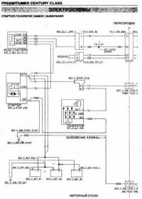
Электросхемы Freightliner Century Class.
- Автор: —
- Издательство: —
- Год издания: —
- Страниц: 43
- Формат: PDF
- Размер: 1,1 Mb
- Manuals
- Brands
- freightliner Manuals
- Trucks
- CENTURY CLASS S
- Driver manual
-
Contents
-
Table of Contents
-
Bookmarks
Related Manuals for freightliner CENTURY CLASS S
Summary of Contents for freightliner CENTURY CLASS S
-
Page 1
CENTURY CLASS S/T ® & CORONADO Driver’s Manual STI-411-2 A24-01036-000… -
Page 2: Reporting Safety Defects
If you believe that your vehicle has a defect which in the vehicle’s workshop and maintenance manuals. could cause a crash or could cause injury or Custom-built Freightliner vehicles are equipped with death, you should immediately inform the National various chassis and cab components. Not all of the…
-
Page 3
Foreword © 1996–2012 Daimler Trucks North America LLC. All rights reserved. Daimler Trucks North America LLC is a Daimler company. No part of this publication, in whole or part, may be translated, reproduced, stored in a retrieval system, or transmitted in any form by any means, electronic, mechanical, photocopying, recording, or otherwise, without the prior written per- mission of Daimler Trucks North America LLC. -
Page 4: Table Of Contents
Contents Chapter Page Introduction, Environmental Concerns and Recommendations, Event Data Recorder, Customer Assistance Center, Reporting Safety Defects ……….. . . Foreword Vehicle Identification .
-
Page 5
Vehicle Identification Vehicle Specification Decal …………1.1 Federal Motor Vehicle Safety Standard (FMVSS) Labels . -
Page 6: Vehicle Identification
Vehicle Identification Vehicle Specification Decal The vehicle specification decal lists the vehicle model, identification number, and major component models. It also recaps the major assemblies and in- stallations shown on the chassis specification sheet. 11/21/96 f080053 One copy of the specification decal is attached to the 1.
-
Page 7: Tire And Rim Labels
Fig. 1.7, Vehicle Noise Emission Control Label 09/28/98 f080023 IMPORTANT: Certain Freightliner incomplete Fig. 1.5, Incomplete Vehicle Certification Label, U.S. vehicles may be produced with incomplete noise control hardware. Such vehicles will not have a vehicle noise emission control information label.
-
Page 8
Vehicle Identification EXHAUST AFTERTREATMENT SYSTEM INFORMATION WARNING INDICATOR STOP CHECK CHECK LAMP(S) (Solid) (Flashing) (Flashing) (Flashing) Level 1 Level 2 Level 3 Level 4 Indicator Lamp Filter Regeneration Filter Regeneration Parked Regeneration Parked Regeneration Required − HEST (High Exhaust Message(s) Recommended Necessary Required −… -
Page 9
Instruments and Controls Identification Instrumentation Control Units …………2.1 Warning and Indicator Lights . -
Page 10: Instruments And Controls Identification
Instruments and Controls Identification Instrumentation Control Units Ignition Sequence The instrumentation control unit (ICU) provides the When the ignition is turned on, the ICU runs a self- driver with engine and vehicle information. It is com- check. Observing the ignition sequence is a good prised of standard and optional gauges, an audible way to ensure the ICU is functioning properly.
-
Page 11: Warning And Indicator Lights
Instruments and Controls Identification Audible Alerts An audible alert sounds during the ignition sequence and whenever one of the following conditions exists: • Engine oil pressure falls below the minimum preset value. • Coolant temperature rises above the maximum preset value. •…
-
Page 12
Instruments and Controls Identification Common Warning and Indicator Lamps Lamp Description Color Indicates a serious fault that requires engine shutdown immediately. The engine protection system reduces the maximum engine torque and speed, and, if the condition does not improve, shuts down the engine within 30 to 60 seconds. -
Page 13
Instruments and Controls Identification Common Warning and Indicator Lamps Lamp Description Color Momentary illumination indicates the vehicle ABS is engaged. Vehicle ABS Solid illumination indicates a problem with the vehicle ABS. Repair the ABS immediately to ensure full braking capability. Momentary illumination indicates the trailer ABS is engaged. -
Page 14: Driver Message Center
Instruments and Controls Identification EXHAUST AFTERTREATMENT SYSTEM INFORMATION INDICATOR WARNING STOP CHECK LAMP(S) (Solid) (Flashing) (Flashing) Level 1 Level 2 Level 3 Level 4 Indicator Lamp Filter Regeneration Filter Parked Regeneration Service Regeneration Required. HEST (High Exhaust Message(s) Recommended. Regeneration Required −…
-
Page 15
Instruments and Controls Identification Parking Brake On This warning message and an audible warning come on whenever the parking brake is applied and the vehicle is moving faster than 2 mph (3 km/h). The screen and audible warning go away only when the General Keys Control Keys Dedicated Keys… -
Page 16: Transmissions
Instruments and Controls Identification Automated Transmission Display Stationary Screens The ICU4M can display current gear information for NOTE: Metric unit screens are similar. AMT= vehicles with an automated transmission. The last Current gear information for automated manual three digits at the far right on the lower line of the transmissions.
-
Page 17
Instruments and Controls Identification advance through the screens. Press and hold the Engine Information SET/RESET key to reset any of the screens. The engine information screens allow you to view engine mileage and hours, and total fuel consump- Fuel Information tion. -
Page 18
Service intervals (OFF/MILES/HOURS); and text message, then take the vehicle to an autho- Target MPG; rized Freightliner service facility as soon as possible. Fig. 2.8 for a diagram of the diagnostic informa- LCD Lamp (ON/OFF);… -
Page 19
Instruments and Controls Identification Return to From Diagnostic Idle Hours Information Screen Distance prior to reaching the Distance traveled beyond the set Service Interval set Service Interval SERVICE INTERVAL IS SET TO 12345 MILES SERVICE WAS DUE INFORMATION AMT XXXXX MILES AMT TO NEXT SERVICE AMT 12345 MILES AGO AMT Go to Set−up Information Screens… -
Page 20: Alert Screens
Instruments and Controls Identification Alert Screens NOTE: If there is more than one alert message to display, press any button to scroll to the next Alert screens can appear at any time, even when the message, and so on until all the messages have vehicle is moving.
-
Page 21
Instruments and Controls Identification If fresh air is not provided after 20 minutes, Provide Fresh Air is displayed. It displays for seven seconds approximately every four minutes until the driver se- NORMAL OPERATION SCREEN lects fresh air on the fresh/air recirculation switch or rotates the air circulation switch away from maximum air conditioning. -
Page 22
Instruments and Controls Identification NOTE: Resetting trip miles and hours also re- To move forward and backward through these screens, use the three arrow buttons on the keypad. sets leg miles and hours. Fig. 2.14, Fig. 2.15, and Fig. 2.16 for stationary To reset a mobile screen, push the Set/Reset button screen navigation. -
Page 23: Instruments
Instruments and Controls Identification applicable SETUP PUSH SET KEY TO TARGET MPG 7.0 INFORMATION Figure. CHANGE TARGET MPG <−−LESS MORE−−> PUSH SET KEY TO DISPLAY BRIGHTNESS CHANGE BRIGHTNESS <−−LIGHT DARK−−> CURRENT LANGUAGE IS FLASHING LANGUAGE ENGLISH PUSH SET KEY TO FRENCH SPANISH CHANGE LANGUAGE CURRENT UNITS…
-
Page 24
Instruments and Controls Identification IDLE HOURS 1234:56 12.3 GAL 1234567 MI FASTEN SEATBELTS 1234567 MILES IGNITION ON ONLY TRIP TRIP MILES 123456.7 IDLE HOURS 1234:56 LEG MILES 123456.7 IDLING INFORMATION TRIP HOURS 1234:56 AVERAGE MPH 12.3 LEG HOURS 1234:56 FUEL FUEL USED 12345.6 IDLE GALLONS 12345.6 INFORMATION… -
Page 25
Instruments and Controls Identification Ammeter tion does not improve, the STOP engine lamp will also illuminate and an audible warning will sound. An ammeter measures current flowing to and from The engine will then derate or shut down, depending the battery. When the batteries are charging, the on the type of engine protection system installed. -
Page 26: Fuel Gauge
Instruments and Controls Identification Primary and Secondary Air Pressure Minimum Oil Pressure Gauges At Idle Speed: At Rated RPM: Engine Model psi (kPa) psi (kPa) Caterpillar 10–20 (69–138) 30–45 (207–310) WARNING Cummins 15 (103) 35 (241) Detroit 14 (97) 55 (350) If air pressure falls below minimum pressure, the Mercedes-Benz 7 (50)
-
Page 27: Controls
11.0 volts. If the voltmeter shows an undercharged or over- charged condition for an extended period, have the charging system and batteries checked at an autho- rized Freightliner service facility. 2.18…
-
Page 28
Instruments and Controls Identification If the trailer is not equipped with spring parking brakes, pull the parking brake valve out to apply the tractor parking brakes and the trailer service brakes. 03/10/99 f610291 1. Trailer Air Supply Valve (red knob) 2. -
Page 29: Cruise Control Switches
Instruments and Controls Identification Cruise control is activated by two dash-mounted switches: an On/Off switch and a Set/Decelerate/ Resume/Accelerate switch. See Fig. 2.23. 10/17/2001 f610591 04/24/2012 f611181 Fig. 2.21, Trailer Brake Lever 1. Set/Decelerate/Resume/Accelerate Switch 2. Cruise Control On/Off Switch Fig.
-
Page 30: Ignition Switch
Instruments and Controls Identification Press the lower half of the On/Off switch. NOTE: To resume the preselected cruise speed, increase vehicle speed to above minimum cruise control speed and momentarily press the upper half of the Set/Resume/Accelerate/ Decelerate switch. Cruise will return to the last speed selected.
-
Page 31: Daytime Running Lights
Instruments and Controls Identification • ether start system Some vehicles may be equipped with a momentary DRL override switch. See Fig. 2.26. Press the upper • air dryer half of the switch to briefly deactivate the DRL. • backup lights Fog Lights Turn the key clockwise past the OFF position to Fog lights are designed to reduce glare in foggy con-…
-
Page 32
Instruments and Controls Identification 04/24/2012 f611174 1. Spotlight Switch 5. Road Lights Switch 8. Fog Lights Switch 2. Dome Light Switch 6. Rear Strobe Light Switch 9. Headlights/Marker Lights Switch 3. Utility Lights Switch 7. Front Strobe Light Switch 10. DRL Override Switch 4. -
Page 33: Pto Switch
Instruments and Controls Identification Baggage Compartment Lights switch or the switch in the sleeper panel to activate the rear cab dome light. See Fig. 2.26. Baggage compartment lights are located on the un- derside of the lower bunk, on both sides. Both lights Sleeper Reading Lights turn on when either baggage compartment door is Clear reading lights are mounted above the lower…
-
Page 34
Instruments and Controls Identification Suspension/Trailer Connection Trailer Auxiliary Switch Controls Some trailers with pneumatic brakes are equipped with power for the trailer lights. The connection is Air Suspension Dump Control Switch passed from the vehicle to the trailer via the primary receptacle, controlled by a dash switch. -
Page 35: Roll Stability Advisor And Control System
Instruments and Controls Identification Roll Stability Advisor and center. The purpose is to advise the driver that the previous maneuver produced a rollover risk. Control System The roll stability advisor displays different text mes- sages depending on the severity of the risk of each The roll stability system may include only the roll sta- occurrence of risky driving.
-
Page 36: Trip/Leg Totals
Instruments and Controls Identification Trip/Leg Totals Message Message to Display Display Buzzer Time: Time: The driver message center records the number of Seconds Seconds messages received, and displays the number of System Fault WARNING messages as counts. Roll stability advisor (RSA) and RAC SYSTEM FAIL hard-braking event data (HBED) counts can be None…
-
Page 37: Voltage And Fuel Efficiency Controls
Instruments and Controls Identification TRIP ADVISORIES 23 ROLL 518 BRK 07/25/2008 f040771 A. RSA Lev. 1 has more than 9 counts. Fig. 2.32, Trip Advisor Message Screen (more than 9 counts) Voltage and Fuel Efficiency 06/19/2007 f545071 Controls Fig. 2.33, Cab Load Disconnect Switch Cab Load Disconnect Switch Low Voltage Disconnect Feature WARNING…
-
Page 38
Instruments and Controls Identification Vehicles equipped with Optimized Idle have a label addition to all functions available in engine on the dash, and a telltale (OPT IDLE) in the ICU. mode. Fig. 2.34 for the dash label detail. If equipped, a Thermostat mode controls the set point, which is the thermostat is located above the sleeper bunk. -
Page 39: Meritor Wabco Antilock Braking System
Instruments and Controls Identification phase, in which the idle speeds up to To deactivate thermostat mode and return to just 1000 rpm, the engine will stop and start engine mode, press and hold the MODE button automatically to keep the battery charged for three seconds.
-
Page 40: Automatic Traction Control
Instruments and Controls Identification • The electronic control unit (ECU) also has a safety If the lamp illuminates momentarily during ve- circuit that constantly monitors the wheel sensors, hicle operation, then shuts off, a fault was de- traction control valve (if equipped), modulator valves, tected and corrected.
-
Page 41: Vorad Vs-400 System
Instruments and Controls Identification and audible indicators whenever following distances become unsafe. ® SmartCruise adjusts the vehicle’s cruise speed in order to match the speed of traffic ahead, allowing the driver to maintain a safe following distance while cruise control is engaged. The optional side object detection system warns of unsafe lane changes by detecting vehicles that may be difficult to see in adjacent lanes.
-
Page 42
Instruments and Controls Identification • Blue: illuminates when information is available Immediately after the ignition switch is turned to ON, the DIU initializes a self-test routine. During the ini- tialization, the VORAD screen displays and all lamps illuminate for approximately three seconds, along System Status with a power-up tone. -
Page 43
Press the OK but- Fig. 2.42. Contact an authorized Freightliner ton to exit the menu. service center if fault codes display. 2.34… -
Page 44: Collision Warning System
Instruments and Controls Identification CWS identifies and tracks the nearest object in the lane of travel. This object is classified by the range, and assigned a message described under the follow- ing headings. DIU DIAGNOSTICS Object Detected SPN: 00886 FMI:012 When a vehicle is detected in the same lane of travel within 350 ft (107 m) but farther than a 3-second fol- lowing distance, the DIU will display OBJECT DE-…
-
Page 45: Side Object Detection
Instruments and Controls Identification DIU will display 2 seconds, and a single tone will sound. See Fig. 2.46. COLLISION ALERT seconds 02/03/2012 f610934a Fig. 2.48, Collision Alert 02/03/2012 f610932a ing distance without disengaging the cruise control. Fig. 2.46, 2-Second Alert The DIU will display the SmartCruise status screen indicating the vehicle’s current set cruise speed.
-
Page 46: Special Road Situations
Instruments and Controls Identification • The side sensor only detects objects within its field of view, next to the tractor. A vehicle be- hind the field of view will not be detected. • The side sensor range is set to detect average-sized vehicles 2 to 10 feet (0.5 to 3 meters) away in the adjacent lane.
-
Page 47: Lane Departure Warning Controls
2.51. The lane departure warning system is not a sub- stitute for safe driving procedures. Contact an authorized Freightliner dealer to review and clear previously active fault codes. Failure to drive safely and use the system prop- erly could result in personal injury and/or death and severe property damage.
-
Page 48: Vehicle Access
Vehicle Access Ignition and Lock Key …………. . 3.1 Cab Door Locks and Handles .
-
Page 49: Vehicle Access
Vehicle Access Ignition and Lock Key One key operates the ignition switch and all of the door locks. IMPORTANT: Each key is numbered. Record the number so, if needed, a duplicate key can be made. Cab Door Locks and Handles To unlock the driver’s door from outside the cab, in- sert the key in the lockset and turn it one-quarter turn clockwise…
-
Page 50
Vehicle Access Be careful not to get hands or feet tangled in Exiting the Driver’s Side (Fig. 3.3) hoses or other back-of-cab equipment. Careless- Exit the cab from the driver’s side as follows: ness could cause a person to trip and fall, with possible injury. -
Page 51
Vehicle Access Grasp the grab handle at the aft edge of the Grasp the grab handle on the windshield post door opening with your left hand. with both hands, and place your right foot on the top step while standing up from the seat facing Grasp the handle on the door (Fig. -
Page 52: Door Windows
Vehicle Access Entering the Passenger’s Side for Sleeper Compartment Vents Right-Hand-Drive Vehicles To open any sleeper compartment vent, push the vent handle outward and forward with your fingertips. When entering the cab from the passenger’s side, To close the vent, turn your hand so that your fingers use the grab handles and access steps as follows: are pulling on the handle from the front edge, then Open the passenger’s door, and place anything…
-
Page 53: Sleeper Door
Vehicle Access Sleeper Door Back-of-Cab Grab Handles, Steps, and Deck Plate The sleeper door (Fig. 3.6, Ref. 1) is not intended for entry or exit. The door is intended only as a conve- When trailer connections cannot be reached conve- nient means to stow or remove personal belongings niently from the ground, Federal Motor Carrier Safety in and from the sleeper area.
-
Page 54: Battery Box Cover
Vehicle Access Move one foot to the bottom step. WARNING Move your upper hand to a lower position on the grab handle. Wet or dirty shoe soles greatly increase the chance of slipping or falling. If your soles are wet Step to the ground with your upper foot first.
-
Page 55: Keyless Security System, Optional
Vehicle Access • A hand-held radio frequency transmitter that looks like a key chain fob. It acts as a remote control for locking the doors, unlocking the doors, or placing the system on alert. Each system allows as many as four different fobs. Fig.
-
Page 56
Vehicle Access How It Works The fob has three push buttons: LOCK, UNLOCK, and ALERT. When a button is pushed, the fob sends a radio frequency signal to the ECM. The signal con- tains a unique vehicle access code that identifies the individual fob, plus codes that indicate which button has been pushed. -
Page 57
Vehicle Access If the ALERT button is pressed, the ECM executes On the fob, press down both the LOCK and UN- the unlock sequence and also activates the vehicle LOCK buttons at the same time and hold them alarm functions (see above). To cancel an ALERT (to down for at least three seconds. -
Page 58: Cab Amenities
Vehicle Access Insert the new battery into the fob. Make sure the battery is right side up. Install the O-ring as removed. If the O-ring is damaged, or there are signs of moisture inside the fob, replace the O-ring. Twist on the battery cover and check it to make sure it is tight.
-
Page 59: Overhead Lights
Vehicle Access and replaced with a CB radio. The grille underneath this portion of the console allows the radio’s speaker to be heard. 11/12/96 f601242 1. Ash Tray 3. Hinged Cover 2. Cigar Lighter 4. Driver’s Cup Holder 10/15/96 f601244 1.
-
Page 60
Vehicle Access 01/15/97 f820190 1. Surge Tank 3. Drain 2. Washer Reservoir Fig. 3.19, Windshield Washer Reservoir 3.12… -
Page 61: Heater And Air Conditioner
Heater and Air Conditioner Blend Air Heater and Air Conditioner System ……… . . 4.1 Water-Valve-Controlled Heater and Air Conditioner System .
-
Page 62: Cab Climate Control Panel
Heater and Air Conditioner Blend Air Heater and Air To increase airflow, turn the switch clockwise or to a higher number. To decrease the airflow, turn the Conditioner System switch counterclockwise or to a lower number. Set- ting the fan switch to the off position disables the air Constant Discharge Temperature conditioner and places the air source in the fresh air Control…
-
Page 63
Heater and Air Conditioner floor outlets. The air conditioner automatically turns on in this mode. The recirculation button will not work in this mode. Defrost Mode: Directs all airflow through the defrost outlets. The air conditioner automatically turns on in this mode. The recirculation button will not work in this mode. -
Page 64: Sleeper Climate Control Panel
Heater and Air Conditioner • Specific conditions exist that result in the ture settings in the sleeper. See Fig. 4.1. Press the heater and air conditioner system going into upper half of the bunk override switch to override the protection mode. sleeper settings with the cab settings.
-
Page 65: Air Outlets
Heater and Air Conditioner Air Outlets The face outlets on the instrument panel have lou- vers that can be moved right and left, and up and down. Move the louvers to the desired location or to close the outlet. The defrost (windshield) outlets and the outlets that are directed at the doors are not ad- justable.
-
Page 66
Heater and Air Conditioner 10/26/95 f830717 1. Fan Switch 2. Air Selection Switch 3. Temperature Control Switch 4. Fresh Air/Recirculation Switch 5. Bunk Fan Switch Fig. 4.7, Climate Control Panel, Heater Only All of the dash-face outlets have adjustable louvers that pivot right, left, up, and down. -
Page 67
Heater and Air Conditioner fresh air rapidly displaces stale air as the cab pres- surizes. IMPORTANT: To prevent the buildup of fumes or odors inside the cab (for example, from smok- ing), do not operate the heater and air condi- tioning system in a recirculation mode for more than 20 minutes. -
Page 68: Fresh Air
Heater and Air Conditioner system. Operate the air conditioner only after Move the temperature control switch counter- clockwise for cool air. In this position, no heat is the engine compartment is warm, and the inte- given off by the heater. rior of the cab is 70°F (21°C) or higher.
-
Page 69: Parked Hvac
Heater and Air Conditioner speed, even with the fan switch in the off posi- When air conditioning is not desired, turn the temperature control switch clockwise and turn tion. This prevents ice from forming on the the fan off. evaporator, especially during humid weather. IMPORTANT: To prevent the buildup of fumes or Turn the temperature control switch all the way odors inside the sleeper (for example, from…
-
Page 70
Heater and Air Conditioner flow or put objectionable odors into the cooling air. Air for the condenser is taken in from under the cab and exhausted through another opening in the cab floor. The system receives power from four deep-cycle bat- teries located between the frame rails. -
Page 71: Seats And Seat Belts
Seats and Seat Belts Seats …………….5.1 Seat Belts and Tether Belts .
-
Page 72: Seats
Seats and Seat Belts Seats Seat Adjustments The following is a description of adjustments that can General Information be made to various Freightliner-installed seats. Not all seats have all of the adjustments listed below. Unless otherwise noted, all seat adjustments should Fig. 5.1.
-
Page 73
Seats and Seat Belts Height Adjustment: The entire seat moves up or down when adjusting the height. The adjustment is either manually or air controlled, depending on the make of the seat. Bottom Cushion Angle or Fore and Aft Bottom Cushion Height: This feature enables the occu- pant to raise or lower the front or back of the bottom cushion. -
Page 74: Freightliner/Bostrom Seat
6. Fore and Aft Adjustment and Isolator Lever 5. Lumbar Support Switch 7. Lumbar Support Knob (non-LSO models) 6. Height Adjustment Switch Fig. 5.4, Freightliner/Bostrom Seat Adjustment Controls Fig. 5.3, EzyRider Seat Adjustment Controls (Vehicles Built on or After November 28, 2005) Weight and Height Adjustment…
-
Page 75: National 2000 Series Seat
Seats and Seat Belts Lumbar Support Height Adjustment To increase lumbar support on LSO models, press Push the height adjustment knob in to inflate the sus- the plus sign on the lumbar support switch. To de- pension and raise the seat. Pull the knob out to de- crease lumbar support on LSO models, press the flate the suspension and lower the seat.
-
Page 76: Seat Belts And Tether Belts
Seats and Seat Belts Seat Belts and Tether Belts General Information Seat belt assemblies are designed to secure persons in the vehicle to help reduce the chance of injury or the amount of injury resulting from accidents or sud- den stops. For this reason, Daimler Trucks North America LLC urges that the driver and all passen- gers, regardless of age or physical condition, use seat belts when riding in the vehicle.
-
Page 77: Seat Belt Inspection
Seats and Seat Belts Seat Belt Inspection Slowly pull the link end of the three-point seat belt out of the retractor and pull it across your lap (from outboard to inboard) far enough to en- WARNING gage the buckle. If the retractor locks too soon, allow the belt to retract slightly, then slowly pull it Inspect and maintain seat belts.
-
Page 78: In An Emergency
Seats and Seat Belts 08/09/2010 f910634 A. Correct—Belt is centered on your shoulder and chest, away from your face and neck. B. Wrong—Belt must not rub against face or neck. C. Wrong—Belt must not hang off shoulder. Fig. 5.8, Proper Shoulder Strap Fit 01/18/95 f910049a Fig.
-
Page 79: Sleeper Compartment Restraints
Seats and Seat Belts allow the belt to retract slightly, then slowly pull it To lengthen the belt, tip the link end downward out again. and pull the link until it connects with the buckle. Fasten the three-point seat belt by pushing the After the belt is connected, shorten it by pulling latch into the buckle.
-
Page 80: Supplemental Restraint System, Optional
Seats and Seat Belts Fasten the belt by pushing the link end into the Do not place objects on the steering wheel or be- buckle until they latch. Make sure that the belt is tween you and the steering wheel. Keep your not twisted.
-
Page 81: Space System, Optional
Seats and Seat Belts • Keep all liquids, acids, halogens, heavy pant of the seat and lower the seat suspension, mov- metals, and heavy salts away from the air ing the occupant down and away from the steering bag system. wheel and ceiling.
-
Page 82
Seats and Seat Belts Safety Guidelines for the SPACE System The SPACE system contains components that use combustible chemicals. Because these chemicals are combustible, care must be taken when replacing or handling system components. WARNING Do not attempt to service the air bag/SPACE sys- tem. -
Page 83
Seats and Seat Belts and the air bag/SPACE system. Cutting or removing the electrical connectors could cause unintentional deployment. • Do not expose the air bag/SPACE system to electricity. Never probe a circuit. • Store, transport, dispose, and recycle de- ployed air bag/SPACE system components in accordance with all applicable federal, state, and local regulations. -
Page 84: Steering And Brake Systems
Steering and Brake Systems Steering System …………..6.1 Brake System .
-
Page 85: Steering System
Steering and Brake Systems Steering System cause, bring the vehicle to a safe stop. Do not drive the vehicle until the cause of the problem has been General Information corrected. When there is no load on the vehicle, and the front WARNING tires are pointed straight ahead, the steering wheel spokes should be centered, ±10 degrees, as shown…
-
Page 86: Brake System Operation
Steering and Brake Systems kPa) pressure in both the primary and secondary After correcting the brake system problem, uncage systems. Monitor the air pressure system by observ- the spring parking brakes before resuming normal ing the dual system air pressure gauge and the low- vehicle operation.
-
Page 87
Steering and Brake Systems 03/10/99 f610291 1. Trailer Air Supply Valve Knob 9/26/95 f461056 2. Parking Brake Valve Knob 1. Turn Signal Lever 2. Trailer Brake Hand Control Valve Fig. 6.3, Brake Valve Knobs 3. Hazard Warning Light Tab vice brakes are wet. To do so could damage the Fig. -
Page 88
Steering and Brake Systems sure supply in the brake chamber to prevent front CAUTION and rear wheel lockup. If equipped with Automatic Traction Control, an addi- Never apply the service and spring parking tional solenoid valve is installed. During reduced- brakes simultaneously. -
Page 89
Steering and Brake Systems • ice, or to help throw off accumulated mud or snow. When the ignition key is turned to the ON posi- SPIN mode is indicated by a flashing WHEEL SPIN tion, the trailer ABS lamp will illuminate mo- light. -
Page 90: Automatic Slack Adjusters
Steering and Brake Systems without the sensor information but at a reduced per- Visit a repair facility as soon as possible when formance level. brakes equipped with automatic slack adjusters are determined to be out of adjustment. If a serious malfunction causes a total switch-off of one or more electronic braking circuits, a pure pneu- WARNING matic backup system is available.
-
Page 91: Engines And Clutches
Engines and Clutches EPA07 Aftertreatment System (ATS) ……….7.1 DD15 Heavy-Duty Engine .
-
Page 92: Epa07 Aftertreatment System (Ats)
Engines and Clutches EPA07 Aftertreatment System eration occurs as the vehicle is driven normally under load; the driver is not even aware that it is (ATS) happening. The harder an EPA07 engine works, the better it disposes of soot, as the exhaust heat alone On-road diesel engines built after December 31, is enough to burn the soot to ash.
-
Page 93
Engines and Clutches high idle speed is being controlled by the engine scheduled for the earliest convenient time. See software, not the driver. Fig. 7.2. A steadily illuminated high temperature (HEST) lamp A DPF lamp blinking at the same time as a steadily alerts the operator of high exhaust temperature dur- illuminated yellow Check Engine lamp, indicates that ing the regeneration process, if vehicle speed is… -
Page 94: Dd15 Heavy-Duty Engine
Engines and Clutches DD15 Heavy-Duty Engine Chapter 2 of this manual for information on the DDEC VI operator controls. See the Detroit Diesel DD15 Engine Operator’s Guide for complete details of engine operation. Engine Protection An engine protection system monitors all engine sen- sors and electronic components, and recognizes sys- tem malfunctions.
-
Page 95: Ddec Vi Driving Tips
Engines and Clutches shutdown sequence. See Fig. 7.3. This override re- air intake arrangement, you may also hear a “chuff- sets the shutdown timer, restoring power to the level ing” sound as the engine starts to pull hard at lower when the red stop engine lamp was illuminated.
-
Page 96
Engines and Clutches header-to-tube stress and possible failure. Winter- erly, by lifting your foot briefly off the accelera- fronts should only be used when the ambient tem- tor pedal. You should feel the system activate. perature remains below 10°F (–12°C). •… -
Page 97: Engine Starting-Cat, Cummins, Dde S60, M-B
Engines and Clutches there is a fishtail motion, turn the engine brake sys- tric priming pump to the priming port on the fuel tem OFF immediately and do not activate it until road filter module. See the engine operation manual conditions improve.
-
Page 98
Engines and Clutches start the vehicle. This could result in a flash fire NOTE: Some starters are equipped with op- causing serious personal injury or property dam- tional overcrank protection. If overcranking age. occurs, a thermostat breaks the electrical circuit to the starter motor until the motor WARNING has cooled. -
Page 99
Engines and Clutches Bring the engine up to operating speed gradually WARNING as it warms up and develops stable oil pressure. NOTE: When the engine is started, it takes a Never pour fuel or other flammable liquid into the short time to build up a lubricating oil film be- air inlet opening in the air intake in an attempt to tween the shafts and bearings, and between the start the vehicle. -
Page 100
Engines and Clutches Turn the ignition switch to the start position. If the engine doesn’t start after 30 seconds of crank- Without touching the throttle pedal, start the en- ing, turn the key to the off position and wait two min- gine. -
Page 101: Starting After Extended Shutdown Or Oil Change-Cat, Cummins, Dde S60, M-B
Engines and Clutches Run the engine slightly above idle until oil pressure If the engine is equipped with a fuel/water sepa- shows on the gauge. If oil pressure doesn’t show on rator, drain off any accumulated water. the gauge within 30 seconds of starting, turn the key Check the drive belts to make sure they are in to the off position and wait one minute;…
-
Page 102: Engine Operation-Cat, Cummins, Dde S60, M-B
Engines and Clutches Engine Operation—CAT, tem in order to bring the vehicle to a safe stop if the engine malfunctions. If the driver doesn’t understand Cummins, DDE S60, M-B how the warning system works, an engine shutdown could cause a safety hazard. See Chapter 2 for in- Operating vehicles with diesel engines in areas…
-
Page 103
Engines and Clutches what rpm is needed to make upshifts under vari- During downhill operation, the crankshaft is turned by ous conditions. This progressive shifting tech- the rear wheels (through the drivetrain). To reduce nique will lower fuel costs because the engine the speed of the vehicle, an application of braking will be operating at the lowest rpm needed to pull force can be made to the crankshaft. -
Page 104
Engines and Clutches technique permits operating within the most eco- safety hazard. See Chapter 2 for information on the nomical power range of the engine. DDEC control panel. All engines have an operating range in which the en- When approaching a hill, open the throttle gine performs most efficiently. -
Page 105
Engines and Clutches while using less fuel and reducing noise. Also, loaded vehicle moving against a grade and it when slowing down for reduced speed zones, won’t harm the engine. remain in your running gear and reduce engine The driver who is not familiar with the vehicle’s rpm to stay within the speed limit. -
Page 106: Cold-Weather Operation-Cat, Cummins, Dde S60, M-B
Engines and Clutches Maintenance literature is also available for driv- same gear used to climb a hill of the same ers of Allison-equipped vehicles who desire grade. trouble-free performance and maximum life from Never allow the engine to exceed the rated their equipment.
-
Page 107
Engines and Clutches • Reasonable starting characteristics followed by If the engine does not start, prime the fuel system. practical and dependable warm-up of the en- When the use of unblended No. 2 diesel fuel in win- gine and equipment. ter cannot be avoided, install a thermostatically con- •… -
Page 108
Engines and Clutches Fuel cloud point is the temperature at which wax engine performance and operation of the elec- crystals become visible, which is generally above tronic engine controls. If a fuel heater is used, the pour point of the fuel. To keep the fuel filter make sure it has thermostatic controls. -
Page 109: High-Altitude Operation-Cat, Cummins, Dde S60, M-B
If the engine is to be operated in arctic tem- tude because the air is too thin to burn as much fuel peratures, consult the nearest Freightliner as at sea level. This loss is about three percent for dealer or an authorized Detroit Diesel engine…
-
Page 110
Engines and Clutches If equipped with an idle shutdown timer, it can be tion chamber, bearings, shafts, etc. This is espe- set to shut the engine down after a preset cially important with turbocharged engines. amount of time. Ninety seconds before the pre- NOTE: Do not idle the engine for excessively set shutdown time, the CHECK ENGINE light will long periods. -
Page 111: Engine Braking System-Cat, Cummins, Dde S60, M-B
Engines and Clutches • Abnormal sounds suddenly occur in the engine The Jake Brake is controlled by a single, dash- or turbocharger. mounted paddle switch with three positions: OFF, LO and HI. With the vehicle stopped, apply the parking brakes and place the transmission in neutral. Jacobs Engine Brake Operation CAUTION WARNING…
-
Page 112
Although throttle pedals. If it fails to activate, take the ve- some braking ability is lost because the valves are hicle to an authorized Freightliner dealer for ser- constantly open, constant-throttle braking is quieter in vice. -
Page 113: Exhaust Braking System-Cat, Cummins, Dde S60, M-B
Engines and Clutches dash controls the engine braking system. Like the haust brake comes on as soon as you remove your engine brake, the constant throttles are deactivated foot from the accelerator pedal. While going down when the accelerator or clutch pedal is depressed. the grade, use a low enough gear to safely descend The ABS system, when active, also deactivates with a minimum application of the service brakes.
-
Page 114: Clutches
Engines and Clutches against your body when the brake is applied. Gear Shifting Techniques The retarding force of the brake may not al- Many drivers upshift into the next gear, or even skip- ways be noticed, but it is actually preventing shift into a higher gear, before the vehicle has the vehicle from going much faster.
-
Page 115
Engines and Clutches Holding the Vehicle on an Incline With a Slipping Clutch A slipping clutch accumulates heat faster than it can be dissipated, resulting in early clutch failures. Never use the clutch as a hill holder. Coasting With the Clutch Released (Pedal Depressed) and the Transmission in Gear Coasting with the clutch released and the transmis-… -
Page 116
Engines and Clutches CAUTION Operating the vehicle with the clutch improperly adjusted could result in clutch or clutch brake failure. Lubrication On vehicles equipped with a greaseable release bearing, the release bearing and linkage should be lubricated at frequent intervals. See Group 25 of the Century Class Trucks Maintenance Manual for inter- vals and procedures. -
Page 117
Transmissions Freightliner SmartShift Shift Control ……….8.1 Eaton Fuller AutoShift Automated Transmissions . -
Page 118: Freightliner Smartshift Shift Control
Transmissions Freightliner SmartShift Shift position (R, N, D) selector switch (Fig. 8.3) is located at the end of the lever. Control ™ General Information, SmartShift The SmartShift transmission control is an electronic transmission control device. It is installed with the following transmissions: •…
-
Page 119
Transmissions section and a 2-speed rear section. The driver must The driver does not need to break torque or increase use the clutch to start and stop the vehicle. or decrease engine speed to synchronize the shift. The transmission signals the engine controller when to break torque and the engine controller automati- cally increases or decreases engine speed. -
Page 120
Transmissions • The DCC (Fig. 8.5) has indicators for reverse, forward or backward, which could result in per- neutral, and the three forward positions: drive, sonal injury and damage to property and the hold, and low. Service and wait lamps are also transmission. -
Page 121
Transmissions NOTE: This allows the speed sensor on the stopped and in drive (either manual or auto- input shaft to get a reading. matic mode). Each pull upward on the control increases the starting gear by one gear, but no Press down on the clutch again and release the higher than fourth gear. -
Page 122
Transmissions Downshifting Operation, AutoShift (without SmartShift) NOTE: With the transmission in drive (D) in the automatic mode, downshifts require no driver WARNING interaction. With the transmission in drive in the manual If the engine cranks in any gear other than neu- mode, request a downshift by pushing downward tral, have the vehicle serviced immediately. -
Page 123: Eaton Ultrashift Dm
Transmissions Move the gear select lever from neutral to drive. Driving in the «H» Mode NOTE: The clutch must be fully depressed to NOTE: You must use the upshift and downshift shift from neutral to drive. buttons on the gear select handle to change gears while in the «H»…
-
Page 124
Transmissions After the ignition is turned on, the current gear indicator shows the dot display, arranged in a square pattern. All dots in the pattern should light up, without gaps or spaces. See Fig. 8.8. 12/22/2003 f270079a To know what gear the transmission is in, look at the current gear indicator. -
Page 125
Transmissions To start from a full stop on hill or grade , quickly move your foot from the brake pedal and press firmly on the throttle pedal. On steep hills, set the parking brake and release it only when there is enough en- gine power to prevent rollback. -
Page 126
Transmissions Automatic Mode (AUTO) In automatic drive mode (AUTO), upshifts and down- shifts are made by the transmission without driver intervention. Press in the neutral lock button, move the selector switch to drive (D), and press down on the throttle pedal. The transmission will shift auto- matically. -
Page 127
Transmissions learning the new load-based shift points, but after that it will handle the shifting automatically. Low (L) is located at the lower end of the four- position selector switch located at the end of the SmartShift control lever. To select L, press in the neutral lock button and move the selector switch to the position below D. -
Page 128
Restart the engine. Ultrashift Diagnostics If the problem continues, contact an authorized Clutch Protection Fault Freightliner or Eaton service facility. Excessive clutch slippage creates heat and reduces Locked In Gear the life of the clutch. These are some conditions which lead to clutch abuse:… -
Page 129: Meritor Sureshift
Transmissions With the service brakes applied, release the NOTE: Neutral is always available during opera- parking brake. tion. When in neutral, upshift and downshift re- quests are ignored. If the mode selector switch Make sure the selector switch is in neutral and is moved from neutral to forward (F) while the turn on the ignition key.
-
Page 130: Zf Meritor Freedomline Automated Transmissions
SmartShift ™ NOTE: If a requested gear is not available, an controller. On Century Class S/T vehicles, dash mes- audible warning will sound and a message will sages will appear on the SmartDash ™…
-
Page 131
Transmissions • To shift down, push the lever down (away from you). On the driver message center display, the first char- acter is blank to indicate manual mode. NOTE: Automatic shifting is possible only in for- ward gear. When the selector switch is in re- verse (R), all shifts are done manually, regard- less of the position of the slide switch. -
Page 132: Eaton Fuller Range-Shift Transmissions
Eaton Fuller Range-Shift transmissions are not syn- Driver Message Center chronized in the front section, but the range section is synchronized to prevent grinding gears during On the Century Class S/T, the gear is displayed on range shifts. ™ the driver display screen in the SmartDash…
-
Page 133
Transmissions transmissions. Be sure to read the shift pattern For all conditions, use the highest gear that is still low enough to start the vehicle moving with decal on the dash for the operating instructions engine idling, and without slipping the clutch for the specific transmission installed in your ve- excessively. -
Page 134
Transmissions 03/13/96 f260027a A. All RT and RTX-B Transmissions D. High Range B. All RTO Transmissions E. Low Range C. All RTX-R Transmissions Fig. 8.15, Eaton Fuller 9-Speed Transmission Shift Patterns Eaton Fuller Shift Progressions LOW RANGE TRANS. HIGH MODEL RANGE Off-Highway On-Highway… -
Page 135: Eaton Fuller Splitter And Range-Shift Transmissions
Transmissions range gears (Table 8.1), double-clutching be- tween shifts. Dir OD Dir OD Downshifting With the transmission in high range, shift pro- gressively downward to the bottom gear in high range, double-clutching between shifts. When in the bottom gear of the high-range shift Dir OD Dir OD pattern, and ready for the next downshift, push…
-
Page 136
Transmissions The other four ratios in the front section are used Never move the splitter control button while in once in low range and once again in high range; neutral. however, each of the five ratios (low–1–2–3–4) in low Do not preselect with the splitter control button; range and each of the four ratios (5–6–7–8) in high after moving the control button, complete the range can be split with the overdrive splitter gear. -
Page 137
Transmissions release the accelerator. Press and release the the accelerator. Press and release the clutch clutch pedal. After releasing the clutch, acceler- pedal. After releasing the clutch, accelerate ate again. again. Continue upshifting through the shift pattern. For 13-speed transmissions: Double-clutch during lever shifts (6th to 7th to Shift upward from low to 1st gear, 2nd, etc. -
Page 138: Eaton Fuller Deep-Reduction Transmissions
Transmissions Downshift through the low range gears as condi- tions require. For 18-speed transmissions: Continue downshifting from 4th overdrive to 4th direct, then 4th direct to 3rd overdrive, 3rd over- drive to 3rd direct, etc. Single-clutch when split shifting (direct to overdrive, overdrive to direct). Double-clutch when making lever shifts (4th to 3rd, 3rd to 2nd, etc.).
-
Page 139
Transmissions Lo Hi Lo Hi DR Lo DR Lo DR Lo DR Lo DR Lo DR Lo DR Lo DR Lo DR Lo DR Lo 03/13/96 f260045a A. Eaton Fuller RT and RTX transmissions shift pattern B. Eaton Fuller RTO transmissions shift pattern 1. -
Page 140
Transmissions Eaton Fuller Shift Progressions DEEP REDUCTION LOW RANGE HIGH RANGE TRANSMISSION Adverse Conditions Off-Highway and On-Highway and Ideal MODEL All Conditions Only Adverse Conditions Conditions 10-Speed RTO LOW− f260333 f260336 f260335 f260337 10-Speed RTX LOW− f260335 f260338 f260339 f260340 15-Speed RTO f260341 f260342… -
Page 141: Meritor Range-Shift Transmissions
Transmissions Downshifting 10-Speed RM and RMX Models With the transmission in high range, shift pro- Meritor 10-speed transmissions have ten evenly- gressively downward to the bottom gear in high spaced forward ratios. Each transmission consists of range, double-clutching between shifts. a 5-speed front section, and a 2-speed auxiliary sec- tion.
-
Page 142
Transmissions 03/13/96 f260156a A. All RM and RMX Transmissions B. All RMO Transmissions C. All RMX-R Transmissions 1. High Range 2. Low Range Fig. 8.21, Meritor 9-Speed RM, RMO and RMX Model Transmissions Shift Patterns Meritor Shift Progressions LOW RANGE TRANS. -
Page 143: Meritor Splitter And Range-Shift Transmissions
Transmissions in 10-speed models. Double-clutch between All of the thirteen speeds are controlled with one shift shifts. See Table 8.3. lever. Built into the shift knob of the lever, are a range selection lever and a splitter control button (on When in the bottom gear of the high-range shift the side of the shift knob), that control range selec- pattern, and ready for the next downshift, push…
-
Page 144: Eaton Fuller Autoselect Automated Transmissions
Transmissions the clutch brake; instead, partially depress the release the clutch pedal. Accelerate the engine clutch pedal, and move the shift lever into neu- only after the transmission has shifted. tral. To downshift from 8th direct to 7th overdrive, flip Release the clutch pedal, and allow the engine the splitter control button up to the overdrive po- to decelerate until the road speed and the engine…
-
Page 145
Transmissions SOLID VOLUME SOLID SERVICE SOLID WAIT HOLD FLASHING SOLID FLASHING 02/16/98 f270055 SOLID A. Console Top View B. Select Handle Side View F270056 1. Shift Tone Volume 4. Upshift Button 02/25/98 Buttons 5. Detent Button A. Driver Display Module 2. -
Page 146
Transmissions Operation, AutoSelect Apply the throttle. NOTE: If the shift is missed, control engine WARNING speed in the direction indicated by the arrows on the display to synchronize engine rpm with If the engine cranks in any gear other than neu- the transmission’s speed. -
Page 147: Eaton Fuller Top 2 And Lightning Semi-Automated Transmissions
NOTE: If the service light stays on or flashes, or Fuller does not illuminate when the engine starts, take the vehicle to an authorized Freightliner or Eaton service facility as soon as possible. Fig. 8.28 for the shift patterns for Lightning and…
-
Page 148
Transmissions NEUTRAL NEUTRAL NEUTRAL AUTO AUTO 02/17/98 f270057 A. 10-Speed Shift Pattern B. 13-Speed Shift Pattern C. 18-Speed Shift Pattern Fig. 8.28, Eaton Fuller Top 2 Shift Patterns When operating off-highway, or under adverse Avoid hunting for neutral by moving the gear shift conditions, always use low gear (if so equipped) lever from the left rail to right rail. -
Page 149: Meritor Engine Synchro Shift (Ess) Automated Models
Transmissions 5th, 5th to 7th, and 7th to 9th. With the shift but- 5th, 5th to 3rd, and 3rd to 1st. With the shift but- ton forward—2nd to 4th, 4th to 6th, 6th to 8th, ton forward—10th to 8th, 8th to 6th, 6th to 4th 8th to 10th.
-
Page 150
Transmissions not have to select ranges. A «break torque» fea- The shift-intent switch (Fig. 8.29) is the upper switch on the driver’s side of the shift handle. It has four ture allows the driver to move the shift lever and positions and controls upshifting and downshifting by take the transmission out of gear without chang- communicating to the ECM the driver’s intention of… -
Page 151
Transmissions Starting The Vehicle Apply pressure with the shift lever toward the neutral position. Ensure that the shift lever is in the neutral (N) Press the top portion of the shift-intent position. switch again, far enough so that the Push the clutch pedal to the bottom of its travel switch goes into a second position inside to engage the clutch brake. -
Page 152: Operation, Allison
Transmissions shift handle body to break torque. The range mission can be programmed to operate as a shift is automatic. 4-speed, 5-speed, or 6-speed unit in the «primary» shift mode. If needed, a «secondary» shift mode can To skip a gear, press the shift-intent switch into be programmed to provide another shift configuration the shift handle, while in neutral, one time for to optimize vehicle use under different operating con-…
-
Page 153
Transmissions 02/17/98 f270061 A. 9-Speed Shift Pattern with LO B. 9-Speed Shift Pattern C. 10-Speed Shift Pattern Gear Fig. 8.32, Meritor ESS 9- and 10-Speed Shift Patterns automatically upshift near the governed speed of the engine. A partially depressed position of the pedal will cause the upshifts to occur at a lower engine speed. -
Page 154: Rear Axles
Rear Axles Meritor Single Drive Axles With Traction Equalizer ……..9.1 Meritor Drive Axles With Main Differential Lock .
-
Page 155: Meritor Single Drive Axles With Traction Equalizer
Rear Axles Meritor Single Drive Axles WARNING With Traction Equalizer Be especially careful when driving under slippery Some Meritor single drive axles are equipped with a conditions with the differential locked. Though traction equalizer which is a load sensing, self- forward traction is improved, the vehicle can still actuating feature.
-
Page 156: Meritor Tandem Drive Axles With Interaxle Differential
Rear Axles the rear axle, so both axles turn together at the same speed. The LOCK position should be used when the vehicle encounters poor traction conditions; however, it also increases drivetrain and tire wear and should be used only when improved traction is required. Meritor Interaxle Differential Lockout Operation To lock the interaxle differential and achieve maxi-…
-
Page 157: Eaton 2-Speed Tandem Axles
Rear Axles moving on the highway, the axle can be shifted to high range. To shift the axle to the high range: Make sure the interaxle differential lockout is disengaged; keep the throttle pedal down; move the range preselection lever to high; release the throttle pedal until the axle shifts;…
-
Page 158
Rear Axles When the interaxle differential lockout control valve is in the UNLOCK position, the interaxle differential al- lows differential action between the axles thereby compensating for different wheel speeds and varia- tions in tire size. Keep the interaxle differential lock- out in the UNLOCK position for normal driving on roads where traction is good. -
Page 159: Fifth Wheels And Trailer Couplings
Fifth Wheels and Trailer Couplings Holland Fifth Wheels …………. 10.1 ASF Castloc II and Simplex Series Fifth Wheels .
-
Page 160
Fifth Wheels and Trailer Couplings Holland Fifth Wheels General Information The 2535 sliding fifth wheel models incorporate a Model 3500 fifth wheel (Fig. 10.1), equipped with either an air-operated release slide, or a manual re- lease slide. Sliding fifth wheel assemblies are mounted on a baseplate which permits forward and rear movement along notched rails. -
Page 161
Fifth Wheels and Trailer Couplings 07/11/2000 f310841 A. Closed Position, Locked B. Open Position, Unlocked 1. Release Handle and Spring 3. Lock Halves 5. Sliding Yoke 2. Adjustment Nut 4. Lock Pivot Fig. 10.4, Type «B» Kingpin Lock Mechanism (bottom view) control handle. -
Page 162
Fifth Wheels and Trailer Couplings 11/07/94 f310106a A. Locks open. B. Locks closed. C. Kingpin correctly entering the lock. Note how the depressed tongue allows lock halves to close completely around the neck and shoulder of the kingpin. D. Kingpin incorrectly entering the lock. Note how the steel tongue prevents lock halves from closing, preventing false lockup. -
Page 163
Fifth Wheels and Trailer Couplings Standard (CMVSS) label attached to the left rear Release the kingpin locking mechanism by pull- door post of the tractor. The desired load on the ing the kingpin lock control handle (Fig. 10.1) to axle is no less than 80 percent of the maximum the outward position. -
Page 164
Fifth Wheels and Trailer Couplings Apply the tractor parking brakes. NOTE: The fifth wheel may have to be moved slightly to enable the locking plungers to enter the fully locked position. Lock the sliding member into position using one of the following methods: WARNING Check to be sure that the slide plungers are in the locked position. -
Page 165
Fifth Wheels and Trailer Couplings WARNING Do not overload any tractor axle by improperly loading the trailer. This could cause erratic steer- ing and loss of vehicle control, possibly resulting in serious personal injury or death. Fifth Wheel Lubrication For lubrication instructions, see Group 31 of the Century Class Trucks Maintenance Manual . -
Page 166
Fifth Wheels and Trailer Couplings Fifth Wheel Lock Mechanism for Trailer pin to move out of the mechanism. With the jaw in the fully open position, the operating rod drops out of Kingpin (Fig. 10.10) the lockset position, and the fifth wheel is ready for coupling. -
Page 167
Fifth Wheels and Trailer Couplings throat of the locking mechanism. Continue back- ward motion until positive lockup occurs. Apply the tractor parking brakes. Make a visual check (even if equipped with the Touchloc air-operated system) for positive king- pin lockup. The trailer bed plate must be flush on the fifth wheel plate surface. -
Page 168
Fifth Wheels and Trailer Couplings 1/8 inch (3 mm), adjust the jaw to restore the Lower the trailer landing gear until the trailer 1/16-inch (1.6-mm) clearance between the jaw rises about 1/2 inch (13 mm). and kingpin. For instructions, see Group 31 of Disconnect the tractor-to-trailer air system lines the Century Class Trucks Workshop Manual . -
Page 169
Fifth Wheels and Trailer Couplings After positive lockup of the fifth wheel lock pins to make sure they have seated in the base- mechanism has been accomplished, release the plate rail holes. slide using one of the following methods: For manually-operated models: Raise the operat- ing rod so that it is free to move inward. -
Page 170
Fifth Wheels and Trailer Couplings Fontaine Fifth Wheels General Information The Fontaine sliding fifth wheel mount is designed to provide optimum axle loading for maximum tractor use with different lengths and types of trailers. The sliding fifth wheel mount is used with the Fontaine H5092 series, and 6000/7000 No-Slack II series fifth wheels, and is equipped with either an air-operated release slide (AWB or HAWB models), or a manual… -
Page 171
Fifth Wheels and Trailer Couplings Fifth Wheel Locking Operation Locking the Fifth Wheel Lock Mechanism NOTICE Before attempting to lock or unlock the fifth wheel lock mechanism of a sliding type fifth wheel, the slide release pull handle, if so equipped, and the slide locking wedges must be in the locked position. -
Page 172
Fifth Wheels and Trailer Couplings Fig. 10.16. This will hold the control handle in WARNING the locked position. Release the tractor parking brakes. Test for king- Incorrect fifth wheel lock adjustment could cause pin lockup by pulling on the trailer against the the trailer to disconnect, possibly resulting in se- chocks. -
Page 173
Fifth Wheels and Trailer Couplings WARNING Do not use the trailer air supply for parking trail- ers not equipped with spring parking brakes. This applies the trailer service brakes only. As air bleeds from the trailer brake system, brake appli- cation is lost. -
Page 174
Fifth Wheels and Trailer Couplings Slowly move the tractor forward or backward axle is no less than 80 percent of the maximum until the fifth wheel is in the desired location. axle weight rating, but in no instances should the axle load exceed the maximum axle weight rat- Apply the tractor parking brakes. -
Page 175
Fifth Wheels and Trailer Couplings 01/20/95 f310312a A. Model 260 B. Model 460 1. Pintle Hook 3. Pawl Assembly 5. Pawl Wedge 2. Latch 4. Pawl Lock 6. Shoe Fig. 10.18, Premier 260 and 460 Trailer Couplings truck while in use, resulting in serious personal injury or property damage. -
Page 176
Fifth Wheels and Trailer Couplings drop into the closed position. Lock the latch by Slowly drive the vehicle away from the trailer. lowering the pawl assembly. Holland Trailer Coupling Model 690: The pintle hook will automatically close and lock from the pressure of the drawbar General Information eye against it. -
Page 177
Fifth Wheels and Trailer Couplings potentially affecting trailer brake or electrical sys- tems. Hook up the trailer’s electrical and air lines. Remove the chocks from the trailer’s tires. Trailer Release Apply the truck and trailer parking brakes. WARNING Do not use the trailer air supply for parking trail- ers not equipped with spring parking brakes. -
Page 178: Pretrip And Post-Trip Inspections And Maintenance
Pretrip and Post-Trip Inspections and Maintenance Pretrip and Post-Trip Inspection Checklists ……….11.1 Daily Pretrip Inspection and Maintenance .
-
Page 179
Pretrip and Post-Trip Inspections and Maintenance Pretrip and Post-Trip Saddle Tank Areas Comp. 3 Frame rails and crossmembers Inspection Checklists 4 Visible exhaust components Periodic Inspections and Engine Compartment Comp. Maintenance, General Information 1 Leakage under engine Regulations in Canada and the U.S. clearly indicate 2 Air intake system that it is the driver’s responsibility to perform an in- 3 Engine oil level… -
Page 180
Pretrip and Post-Trip Inspections and Maintenance Weekly Post-trip Inspection Checklist Fluids Added See the following table for procedures that should be Use the following table to note any fluids that were performed weekly, post-trip. Place a check mark in added during the inspection and maintenance proce- the complete (Comp.) column to indicate a proce- dures. -
Page 181: Wheel And Tire Inspection
Pretrip and Post-Trip Inspections and Maintenance Daily Pretrip Inspection and Maintenance Complete the following inspection and maintenance procedures to ensure that vehicle components are in good working condition before each trip. A driver who is familiar with the vehicle and drives it regularly can perform the daily inspections, then add the weekly and monthly post-trip inspections as scheduled.
-
Page 182
Pretrip and Post-Trip Inspections and Maintenance 10/11/2005 f421397 A. Rotate the control arm toward the brake chamber until it can be felt contacting the internal stop. 1. Clevis 6. Control-Arm Washers 2. Slack Adjuster and Nut 3. Clevis Pin 7. Anchor Strap Slot 4. -
Page 183
Pretrip and Post-Trip Inspections and Maintenance correct tire inflation pressure for the vehicle load. Examine each rim and wheel component. Remove all dirt and debris from the as- sembly. Rust streaks or metal build-up around stud holes, or out-of-round or worn stud holes, may be caused by loose wheel nuts. -
Page 184
Pretrip and Post-Trip Inspections and Maintenance air dryer, it will not remove the water from the air Check the air intake duct from the air brake system, which could adversely affect brak- cleaner to the engine intake. Make sure ing. the duct components are secure and air- tight. -
Page 185
Pretrip and Post-Trip Inspections and Maintenance If the surge tank was empty, start the en- gine after refilling and check the level again when the engine is at operating temperature. Inspect visible engine wiring for damage or looseness. Check for loose wiring, chafed insula- tion, and damaged or loose hold-down clamps. -
Page 186
Pretrip and Post-Trip Inspections and Maintenance With the air system fully charged, make WARNING one full brake application and note the air pressure reading on the primary air When cleaning windshields and windows, always gauge. stand on the ground or on a secure ladder or Further reduce air pressure using moder- platform. -
Page 187
Pretrip and Post-Trip Inspections and Maintenance fire and resulting in serious personal injury or death by burning. Do not mix gasoline or alcohol with diesel fuel. This mixture could cause an explosion, possibly resulting in serious personal injury or death. Do not fill the fuel tanks in the presence of sparks, open flames, or intense heat. -
Page 188
Pretrip and Post-Trip Inspections and Maintenance comply with the washer fluid manufacturer’s rec- NOTE: A hose may be used to direct water ommended safety precautions. into the container. Use a hose with a ½-inch pipe thread on DAVCO models. Check the windshield washer reservoir fluid level. If the engine is equipped with a built-in After resetting the air intake restriction indicator water separator, loosen the drain valve,… -
Page 189: And Maintenance
Pretrip and Post-Trip Inspections and Maintenance 05/05/2009 f470506b 1. Drain Valve 4. Vent Cap 2. Lower Housing 5. Collar 10/11/2001 f461916 3. Clear Cover 6. Inlet Port/Check Valve 1. Steering Gear Mounting Bolts 2. Pitman Arm Pinch Bolt Nut Fig. 11.10, DAVCO Fuel/Water Separator (Fuel Pro 382 3.
-
Page 190
Pretrip and Post-Trip Inspections and Maintenance Inspect the batteries. NOTICE WARNING If the external breather tube or breather cap is missing or incorrectly installed, road dirt and de- Battery posts, terminals, and related accessories bris can adversely affect the operation of the contain lead and lead compounds, chemicals brake chamber. -
Page 191
Extended-service-life silicone hoses may also be used. See the Alliance Parts Catalog at www.alliancebrandparts.com contact a Freightliner Dealer. Check the steering wheel for excessive play. Start the engine. With the front tires straight ahead, turn the steering wheel until motion is observed at the front wheels. -
Page 192: Cab Appearance
Cab Appearance Cab Washing and Polishing …………12.1 Care of Fiberglass Parts .
-
Page 193: Cab Washing And Polishing
UV coating all road tar and tree sap before waxing. from the surface, and result in yellowing of the Freightliner recommends that a quality brand of lens. cleaner or cleaner-polish and polishing wax be used.
-
Page 194: Ordinary Dirt
Cab Appearance vinyl upholstery. To preserve the upholstery and pre- drogen peroxide onto the cloth. Allow the saturated vent damage, carefully review the following sections cloth to remain on the spot for 30 to 60 minutes. For for recommended cleaning procedures. Waxing or stubborn spots, allow the hydrogen-peroxide satu- refinishing improves soil resistance and cleanability rated cloth to remain on the area overnight.
-
Page 195: Chewing Gum Or Wax
Cab Appearance Grease and Oil-Based Stains Dampen a small absorbent cloth with dry-cleaning solvent or spot remover. Apply the cloth carefully to the spot from the outer edge to the center. Pat and blot the spot with a clean, dry cloth. Repeat several times, as necessary, turning the cloths so that the stain does not redeposit on the fabric.
-
Page 196
In an Emergency Hazard Warning Lights …………13.1 Fire Extinguisher . -
Page 197: In An Emergency
In an Emergency Hazard Warning Lights WARNING The hazard warning light switch tab is located on the Use extreme care when placing flares in emer- turn signal control lever. See Fig. 13.1.To operate the gency situations that involve exposure to flam- hazard lights, pull the tab out.
-
Page 198: Rear Towing Hookup
In an Emergency Cover the ends of the hubs with metal plates or On vehicles equipped with an air fairing, repeat plywood cut to fit the axle opening, and drilled to the measurement taken in step 8. The difference fit the axle shaft studs. This prevents lubricant between the two measurements must not exceed from leaking out, and will keep contaminants 14 inches (36 cm).
-
Page 199: Emergency Starting With Jumper Cables
In an Emergency f880694 01/11/2006 IMPORTANT: Do not reeve when towing. 1. Tow Hook 2. Chain Fig. 13.2, Reeving Lift the vehicle, and secure the safety chains. If CAUTION extra clearance is needed, remove the bumper extension, if equipped. Make sure both starting systems have the same Connect the clearance lights, taillights, and sig- voltage outputs, and avoid making sparks.
-
Page 200
In an Emergency WARNING Do the next step exactly as instructed and do not allow the clamps of one cable to touch the − clamps of the other cable. Otherwise, a spark could occur near a battery, possibly resulting in −… -
Page 201
Index Subject Page Subject Page Cab-to-Sleeper Access ….. 3.4 Canadian Motor Vehicle Safety Standard (CMVSS) Labels ….1.1 Air Bag, Optional . -
Page 202
….10.11 Emergency Starting With Freightliner SmartShift Shift Jumper Cables ……13.3 Control . -
Page 203
Index Subject Page Subject Page General Information, Engine Oil Pressure Gauge ….2.16 SmartShift ™ ……8.1 Engine Oil Temperature Gauge . -
Page 204
……2.28 Freightliner/Bostrom Seat ….5.3 Cab Load Disconnect Switch . -
Page 205
Index Subject Page Low Voltage Disconnect Feature ……2.28 Optimized Idle ® ….. . . 2.28 VORAD VS-400 System .
This manual is also suitable for:
Coronado
- Manuals
- Brands
- Freightliner Manuals
- Trucks
- CENTURY CLASS S
Manuals and User Guides for Freightliner CENTURY CLASS S. We have 1 Freightliner CENTURY CLASS S manual available for free PDF download: Driver Manual

Freightliner CENTURY CLASS S Driver Manual (205 pages)
Brand: Freightliner
|
Category: Trucks
|
Size: 4.52 MB
Table of Contents
-
Table of Contents
4
-
Reporting Safety Defects
2
-
Vehicle Specification Decal
6
-
Federal Motor Vehicle Safety Standard (FMVSS) Labels
6
-
Canadian Motor Vehicle Safety Standard (CMVSS) Labels
6
-
Vehicle Identification
6
-
Tire and Rim Labels
7
-
EPA Emission Control
7
-
-
Instruments and Controls Identification
9
-
Instrumentation Control Units
10
-
Instruments and Controls Identification
10
-
Engine Protection System
11
-
-
Warning and Indicator Lights
11
-
Driver Message Center
14
-
Automated Transmission Display
16
-
Transmissions
16
-
Alert Screens
20
-
Instruments
23
-
Fuel Gauge
26
-
Controls
27
-
Cruise Control Switches
29
-
Ignition Switch
30
-
Engine Fan Switch
30
-
Daytime Running Lights
31
-
Pto Switch
33
-
-
Roll Stability Advisor and Control System
35
-
Trip/Leg Totals
36
-
Cab Load Disconnect Switch
37
-
Idle Shutdown Timer
37
-
-
Voltage and Fuel Efficiency Controls
37
-
Meritor WABCO Antilock Braking System
39
-
Automatic Traction Control
40
-
Trailer Abs Compatibility
40
-
Driver Interface Unit
41
-
-
VORAD VS-400 System
41
-
Collision Warning System
44
-
Side Object Detection
45
-
Special Road Situations
46
-
-
Lane Departure Warning Controls
47
-
-
Vehicle Access
48
-
Cab Door Locks and Handles
49
-
Grab Handles and Access Steps
49
-
Ignition and Lock Key
49
-
Vehicle Access
49
-
Cab-To-Sleeper Access
52
-
Circuit Breaker/Relay Panel
52
-
Door Windows
52
-
Sleeper Bunk Latches
52
-
Sleeper Compartment Vents
52
-
Back-Of-Cab Grab Handles, Steps, and Deck Plate
53
-
Baggage Compartment Doors
53
-
Sleeper Door
53
-
Battery Box Cover
54
-
Hood Tilting
54
-
Keyless Security System, Optional
55
-
General Information
55
-
-
Cab Amenities
58
-
Overhead Lights
59
-
Footwell Lights
59
-
Map Holder
59
-
-
Windshield Washer Reservoir
59
-
Glove Box
59
-
-
Heater and Air Conditioner
61
-
Cab Climate Control Panel
62
-
Sleeper Climate Control Panel
64
-
Air Outlets
65
-
Fresh Air
68
-
Parked Hvac
69
-
-
-
-
Seats and Seat Belts
71
-
Seats
72
-
Freightliner/Bostrom Seat
74
-
Dura-Form Fleetcruiser Seat
75
-
National 2000 Series Seat
75
-
-
Seat Belts and Tether Belts
76
-
Seat Belt Inspection
77
-
Seat Belt Operation
77
-
In an Emergency
78
-
Bunk Restraint Adjustment
79
-
Bunk Restraint Operation
79
-
-
Sleeper Compartment Restraints
79
-
Air Bag, Optional
80
-
Air Bag Safety Guidelines
80
-
-
Supplemental Restraint System, Optional
80
-
SPACE System, Optional
81
-
Steering and Brake Systems
84
-
Brake System
85
-
Power Steering System
85
-
Brake System Operation
86
-
Automatic Slack Adjusters
90
-
-
Steering System
85
-
-
Engines and Clutches
91
-
EPA07 Aftertreatment System (ATS)
92
-
Index
92
-
-
DD15 Heavy-Duty Engine
94
-
Engine Protection
94
-
Ddec VI Driving Tips
95
-
-
-
Engine Starting-CAT, Cummins, DDE S60, M-B
97
-
Engine Break-In-CAT, Cummins, DDE S60, M-B
101
-
Starting after Extended Shutdown or Oil Change-CAT, Cummins, DDE S60, M-B
101
-
Engine Operation-CAT, Cummins, DDE S60, M-B
102
-
Cold-Weather Operation-CAT, Cummins, DDE S60, M-B
106
-
Engine Shutdown-CAT, Cummins, DDE S60, M-B
109
-
High-Altitude Operation-CAT, Cummins, DDE S60, M-B
109
-
Engine Braking System-CAT, Cummins, DDE S60, M-B
111
-
Exhaust Braking System-CAT, Cummins, DDE S60, M-B
113
-
Clutches
114
-
Clutch Operation
114
-
-
-
Transmissions
117
-
Eaton Fuller Autoshift Automated Transmissions
118
-
Freightliner Smartshift Shift Control
118
-
Eaton Ultrashift DM
123
-
Meritor Sureshift
129
-
ZF Meritor Freedomline Automated Transmissions
130
-
Operation, Freedomline
130
-
-
Eaton Fuller Range-Shift Transmissions
132
-
Eaton Fuller Splitter and Range-Shift Transmissions
135
-
Eaton Fuller Deep-Reduction Transmissions
138
-
Meritor Range-Shift Transmissions
141
-
Meritor Splitter and Range-Shift Transmissions
143
-
Eaton Fuller Autoselect Automated Transmissions
144
-
Eaton Fuller Top 2 and Lightning Semi-Automated Transmissions
147
-
Meritor Engine Synchro Shift (ESS) Automated Models
149
-
Operation, Allison
152
-
-
Allison Automatic Transmissions
152
-
-
Rear Axles
154
-
Meritor Drive Axles with Main Differential Lock
155
-
Meritor Main Differential Lock Operation
155
-
Meritor Single Drive Axles with Traction Equalizer
155
-
Rear Axles
155
-
-
Eaton Single Reduction Axles with Controlled Traction Differential
156
-
Meritor Interaxle Differential Lockout Operation
156
-
Meritor Tandem Drive Axles with Interaxle Differential
156
-
Eaton 2-Speed Tandem Axles
157
-
Eaton Interaxle Differential Lockout Operation
157
-
Fifth Wheels and Trailer Couplings
159
-
Pretrip and Post-Trip Inspections and Maintenance
178
-
Wheel and Tire Inspection
181
-
And Maintenance
189
-
Brake Component Inspection
189
-
-
-
Cab Appearance
192
-
Cab Washing and Polishing
193
-
Care of Chrome Parts
193
-
Care of Exterior Lights
193
-
Dashboard Care
193
-
Care of Fiberglass Parts
193
-
Vinyl Upholstery Cleaning
193
-
Ordinary Dirt
194
-
Shoe Polish
194
-
Ball Point Ink
194
-
Chewing Gum
194
-
Velour Upholstery Cleaning
194
-
Chewing Gum or Wax
195
-
Grease and Oil-Based Stains
195
-
-
In an Emergency
197
-
Fire Extinguisher
197
-
Emergency Kit, Optional
197
-
Rear Towing Hookup
198
-
Emergency Starting with Jumper Cables
199
-
-
Advertisement
Advertisement
Related Products
-
Freightliner Columbia
-
freightliner Cascadia CA113SLP
-
freightliner Cascadia CA125DC
-
freightliner Cascadia CA125SLP
-
freightliner CENTURY CLASS 2011
-
freightliner Argosy COE 2011
-
freightliner C112 Conventional 2011
-
freightliner Coronado 2011
-
freightliner COLUMBIA 2015
-
freightliner CL112 2015
Freightliner Categories
Trucks
Automobile
Automobile Accessories
Car Video System
Car Receiver
More Freightliner Manuals
Сокращения и условные обозначения 3
Идентификация 3
Моменты затяжки 7
Руководство по эксплуатации 9
Блокировка дверей 9
Противоугонная система 9
Комбинация приборов 10
Индикаторы комбинации приборов 12
Информационный дисплей 13
Стеклоподъемники 14
Капот 14
Спальный отсек 14
Стеклоочистители и омыватели 15
Световая сигнализация на автомобиле 15
Внутреннее освещение кабины 16
Регулировка положения рулевого колеса 16
Коробка отбора мощности 16
Экономия электроэнергии аккумуляторной батареи 16
Системы увеличения топливной экономичности 17
Сиденья 17
Ремни безопасности 18
Меры предосторожности при эксплуатации
автомобилей, оборудованных системой SRS 19
Отопитель и кондиционер 19
Стояночный тормоз 21
Основной тормоз прицепа 21
Торможение двигателем 21
Система поддержания скорости 21
Антиблокировочная тормозная система (ABS) 22
Противобуксовочная система (АТС) 22
Система устойчивости к крену 23
Система экстренного торможения (НВА) 23
Система переключения передач SmartShift™ 24
Особенности трансмиссии моделей 4WD 26
Система изменения высоты расположения задней
подвески 26
Система VORAD VS-400 26
Система контроля движения по полосе 28
Блокировка тягово-сцепного устройства 28
Запуск двигателя 29
Остановка двигателя (модели с турбонаддувом) 30
Неисправности двигателя во время движения 30
Прожиг сажевого фильтра 31
Советы по вождению в различных условиях 32
Буксировка автомобиля 32
Инструменты 33
Поддомкрачивание автомобиля 33
Замена колеса 33
Рекомендации по выбору шин 34
Проверка давления и состояния шин 34
Замена шин 35
Проверка и замена предохранителей 35
Замена ламп 36
Расположение портов двигателя 37
Двигатель 42
Дополнительный масляный фильтр 42
Общая информация 42
Модель Fleetguard LF 750™ 42
Модель Luber-finer® 750-CT 42
Модель Spinner II® 42
Фильтрующий элемент фильтра Luber-finer® 43
Центрифуга фильтра Spinner II 43
Система облегчения холодного пуска (эфир) 44
Общая информация 44
Емкость пускового топлива 44
Моторный тормоз Jacobs, модели 760А и 765 44
Общая информация 44
Аккумулятор 45
Электромагнитный клапан 46
Управляющий клапан 46
Корпус моторного тормоза 47
Главный поршень 47
Регулировочный винт исполнительного поршня 48
Исполнительный поршень 48
Шкивы и ремни 49
Двигатель Detroit Diesel серии 60 50
Двигатель в сборе 50
Ремни навесных агрегатов — замена 50
Информация по двигателям ЕРА07 52
Общая информация 53
Опоры двигателей 53
Задняя опора 53
Передняя опора 53
Задняя опора двигателей по ЕРА07 54
Двигатель Caterpillar C-10 55
Замена ремней привода навесных агрегатов 55
Радиатор системы охлаждения
двигателя 56
Общая информация 56
Радиатор до ЕРА07 56
Система охлаждения 57
Вентилятор радиатора 57
Радиатор 1350 кв дюймов 57
Радиатор ЕРА07 58
Быстросъемные фитинги QLD 59
Муфта вентилятора радиатора 60
Муфта Kysor K22RA 60
Муфта Horton DriveMaster 62
Система подготовки топлива 65
Общая информация 65
Топливный бак 65
Стропа топливного бака 66
Кронштейн топливного бака 66
Подогреватель топлива Arctic Fox 67
Подогреватель топлива Webb 67
Топливо/водяной сепаратор ConMet 68
Топливо/водяной сепаратор Alliance/Racor 69
Топливо/водяные сепараторы DAVCO 70
Обратный и байпасный клапаны 72
Охладитель топлива Hayden 74
Электронная педаль акселератора 75
Система впуска воздуха 76
Воздушный фильтр 76
Общая информация 76
Впускной воздуховод 76
Фильтрующий элемент 76
Корпус воздушного фильтра 76
Охладитель наддувочного воздуха 77
Общая информация 77
ОНВ двигателей до ЕРА07 77
ОНВ двигателей ЕРА07 78
Промывка ОНВ 78
Система выпуска 79
Общая информация 79
Трубы системы выпуска с креплением на раме 82
Тепловой экран 82
Широкий хомут 82
Колено трубы глушителя 83
Глушитель (крепление к кабине) 83
Глушитель (крепление к раме) 84
Система очистки отработавших газов ЕРА07 84
Общая информация 84
Устройство очистки отработавших газов 85
Сильфон 86
Воздушный компрессор 88
Компрессор Bendix серий 550 и 750 88
Компрессор Bendix DuraFlo 596 90
Компрессоры Bendix BA-921/922 и Bendix ЗбОсс 91
Сцепление 94
Сцепление Eaton Fuller 94
Общее описание 94
Регулировки сцепления 95
Сцепление в сборе 96
Регулировка сцепления 102
Управление сцеплением 103
Сцепление Meritor™ «Lite Pedal» 105
Общая информация 105
Регулировки сцепления 105
Сцепление в сборе 106
Механическая коробка перемены
передач 110
Снятие 110
Установка 110
Система переключения передач SmartShift™ 111
Рычаг управления 112
Замена масла КПП 112
Карданная передача 113
Общая информация 113
Шарнир полукруглой вилки 116
Сборка 116
Шарнир круглой вилки 118
Карданный вал 119
Карданный шарнир 124
Компенсатор длины 125
Вилки концевых карданных шарниров 125
Очистка и осмотр деталей карданной передачи 126
Замена, сборка или установка деталей карданной
передачи 128
Спецификация 130
Углы наклона карданной передачи — общее 131
Угол наклона осей двигателя и агрегатов 131
Углы наклона карданной передачи 132
Спецификация 133
Подвеска 137
Передняя рессорная подвеска 137
Общая информация 137
Листовая рессора 137
Втулка кронштейна серьги 139
Втулка рессоры 139
Амортизатор 139
Спецификация 140
Задняя рессорная подвеска, один мост 141
Общее описание 141
Продольная тяга 141
Листовая рессора 141
Кронштейны рессоры 142
Регулирование положения заднего моста 142
Спецификация 142
Задняя рессорная подвеска, сдвоенные мосты143
Общее описание 143
Продольная тяга 143
Балансир 144
Листовая рессора 144
Кронштейны рессоры 145
Регулировка положения задних мостов 145
Спецификация 146
Задняя подвеска Freightiiner Airliner 146
Клапан регулирования высоты подвески 146
Проверка клапана регулировки высоты подвески 148
Клапан регулировки высоты подвески 150
Амортизатор 150
Пневматическая пружина 150
Регулировка осевого положения заднего моста 152
Регулировка колеи заднего моста 152
Поперечная тяга 152
Втулка ушка рессоры 153
Спецификация 153
Подвеска Freightiiner Airliner Plus™ 153
Общая информация 153
Электронный блок управления 153
Электромагнитный клапан 153
Датчик высоты подвески 154
Поиск неисправностей 154
Задняя рессорная подвеска TufTrac™ 155
Описание 155
Центральный подшипник 155
Амортизатор 155
Листовая рессора 155
Реактивные тяги 156
Кронштейн моста и держатель моста 157
Задняя подвеска Chalmers 854 158
Общее описание 159
Резиновая пружина 159
Амортизатор 159
Балансир 159
Тяги подвески 160
Регулирование положения задних мостов 161
Задняя подвеска Hendrickson RT2 и RTE2 162
Описание 162
Задняя подвеска Hendrickson RT2 и RTE2 162
Реактивные тяги и втулки 163
Задняя подвеска Hendrickson RS 164
Описание 164
Задняя подвеска Hendrickson RS 164
Седло 165
Передняя подвеска AirLiner
(Hendrickson AIRTEK) 166
Общая информация 166
Высота подвески 166
Клапан регулировки высоты подвески 167
Амортизатор 167
Пневматическая пружина 167
Листовая рессора 169
Кронштейны рессоры 169
Колеса и шины 171
Общая информация 171
Колеса 171
Предостережения при замене шин 172
Бескамерные шины 173
Проверка 173
Накачивание шины 174
Передний мост 175
Предварительные проверки 175
Углы поворота управляемых колес 176
Угол развала передних колес 176
Угол продольного наклона шкворня 176
Схождение колес 177
Передний мост 177
Спецификация 177
Ступицы колес переднего моста, тормозные
барабаны и колесные подшипники 178
Общая информация 178
Мост Meritor FF-981 Easy Steer Plus 178
Колесная ступица 178
Проверка деталей 180
Фиксация регулировочной гайки подшипника
(из 4-х частей) 181
Унифицированная ступица Meritor 182
Фиксация регулировочной гайки подшипника
(система Pro-Torq®) 182
Тормозной барабан 184
Колесный подшипник 184
Шпильки крепления колеса 185
Регулировочная гайка подшипника системы Axilok 185
Осевой зазор унифицированной ступицы Meritor 186
Общая информация 187
Замена сальника 188
Передний мост Freightiiner 192
Поворотный кулак 192
Смазка шкворня 193
Задний мост 194
Ориентация заднего моста 194
Общая информация 194
Предварительные проверки 194
Проверка положения единственного заднего моста 194
Проверка положения первого заднего моста 195
Изготовление штангенциркуля 195
Ступицы колес, подшипники, тормозные
барабаны 195
Общая информация 195
Колесная ступица 196
Проверка деталей 197
Колесный подшипник 197
Шпильки полуоси 197
Фиксация регулировочной гайки подшипника
(из 4 частей) 197
Фиксация регулировочной гайки подшипника
(Pro-Torq®) 197
Шпильки крепления колеса 198
Фиксация регулировочной гайки подшипника Axilok 198
Спецификация 198
Сальники заднего моста 198
Задние мосты Detroit ™ 198
Общая информация 198
Единственный или второй мост 198
Редуктор единственного или второго моста 199
Полуось 200
Первый задний мост 200
Редуктор первого заднего моста 201
Проходной вал 201
Вилка и сальник редуктора единственного или второго
заднего моста 202
Вилка и сальник редуктора первого заднего моста 202
Блокировка дифференциала (DCDL) 203
Блокировка межосевого дифференциала 204
Резьбовое кольцо 204
Межосевой дифференциал 205
Рулевое управление 208
Карданная передача рулевого управления
Spicer Lite® 208
Чехол компенсатора длины карданной передачи
Spicer 209
Проверка карданной передачи Spicer Lite® 209
Продольная рулевая тяга 210
Пыльник шарового шарнира продольной рулевой тяги 211
Фиксированная рулевая колонка 211
Общая информация 211
Рулевое колесо 211
Рулевая колонка 212
Рулевая колонка с регулировкой наклона 213
Общая информация 213
Рулевое колесо 213
Рулевая колонка 215
Рулевой механизм Sheppard M100 216
Рулевой механизм 216
Сальник входного вала 216
Вал сектора 217
Плунжер разгрузки 218
Рулевая сошка 220
Проверки после ремонта 220
Спецификация 221
Насос усилителя рулевого управления,
серия PS TRW 221
Принцип работы 222
Насос в сборе 222
Карданная передача рулевого управления,
ZF 224
Карданная передача : 224
Рулевая колонка с регулируемым наклоном,
TRW 225
Общая информация 225
Рулевое колесо 225
Рулевая колонка 226
Рулевые механизмы, модели TRW THP/PCF 226
Рулевой механизм 227
Заправка и прокачка системы рулевого управления 228
Сальник входного вала рулевого механизма 228
Вал сектора 229
Тарельчатые клапаны 230
Проверки после ремонта 230
Общая информация 231
Рейка-сектор • 231
Рулевой механизм в сборе 232
Сальник входного вала 232
Наконечник рулевой тяги 233
Чехол рулевой тяги 234
Рулевой механизм Sheppard HD94 235
Принцип работы 235
Рулевой механизм 235
Рулевая сошка 235
Сальник входного вала 235
Сальник вала сектора 235
Плунжер разгрузки 236
Прокачка системы 237
Общая информация 238
Рулевой механизм 239
Сальник входного вала 239
Вал сектора 239
Тарельчатые клапаны 239
Заправка и прокачка системы рулевого управления 239
Проверки после ремонта 239
Тормозная система 240
Меры предосторожности 240
Тормоза Meritor Cam-Master Q Plus 240
Принцип действия 241
Тормозные колодки 241
Регулировка тормоза 243
Накладки тормозных колодок 245
Детали тормоза 246
Спецификация 249
Тормоза Dana Spicer ES 250
Принцип действия 250
Тормозная колодка 250
Накладки тормозных колодок 252
Детали тормоза ,253
Регулировка тормоза 256
Модуль осушителя воздуха Bendix DRM 256
Общая информация 256
Меры предосторожности 257
Осушитель 258
Картридж осушителя 259
Нагнетательный обратный клапан и регулятор 259
Клапан очистки 259
Нагреватель и термостат 260
Воздушный ресивер 260
Эксплуатационные тесты 260
Осушитель воздуха Bendix AD-9 261
Общее описание 261
Меры предосторожности 263
Осушитель AD-9 263
Управление стояночными тормозами
Bendix MV-3 265
Общая информация 265
Внутренний обратный клапан 266
Воздушные трубки/шланги и фитинги 267
Монтаж трубок и шлангов 267
Монтаж фитингов 267
Спецификация 267
Двойной тормозной клапан Bendix E-6 269
Общая информация 269
Тормозной клапан 269
Автоматический компенсатор износа Gunite 271
Общая информация 271
Компенсатор износа 271
Автоматический компенсатор износа
Haldex (SAB) и Dana Spicer 272
Общее описание 272
Принцип работы 272
Компенсатор износа 272
Регулировка тормоза 273
Автоматический компенсатор износа Meritor 274
Тандемные тормозные камеры MGM «TR» 277
Принцип действия 277
Силовая пружина 277
Диафрагма основного тормоза 278
Тандемные тормозные камеры Anchorlok 280
Общая информация 280
Принцип действия 280
Силовая пружина 281
Диафрагма основного тормоза 282
Тормозная камера 282
Тормозная камера основного тормоза
Midland 283
Общая информация 283
Принцип работы 283
Тормозная камера 283
Диафрагма тормозной камеры 283
Тормозная камера 283
Спецификация 284
Автоматический дренажный клапан
BendixDV-2 284
Принцип работы 284
Клапан DV-2 284
Двойной обратный клапан Bendix DC-4 285
Общее описание 285
Двойной обратный клапан Bendix DC-4 285
Клапан немедленного разъединения
Bendix QR-1C 286
Принцип действия 286
Меры предосторожности 286
Клапан Bendix QR-1C 286
Клапан предохранения тягача
Bendix TP-3DC 287
Принцип действия 287
Начальная зарядка 287
Включение основного тормоза 287
Прекращение торможения 288
Предохранение тягача 288
Разделение тормозов 288
Меры предосторожности 288
Клапан предохранения тягача Bendix TP-3DC 289
Клапан-модулятор Bendix SR-7 290
Принцип действия 290
Зарядка привода пружинного тормоза,
давление ниже 107 psi (737 кПа) 290
Зарядка привода пружинного тормоза,
давление выше 107 psi (737 кПа) 290
Рабочее состояние 291
Парковка 291
Основные тормоза с потерей воздуха в первичной
цепи 291
Основные тормоза с потерей воздуха во вторичной
цепи 291
Разделение тормозов 291
Клапан-модулятор Bendix SR-7 292
Антиблокировочная тормозная система
(ABS) Meritor WABCO 293
Общее описание 293
Принцип действия 293
Датчики частоты вращения колеса 293
Электронный блок управления (ECU) 293
Меры предосторожности 295
Датчик частоты вращения колеса 295
Датчик частоты вращения заднего колеса 296
Модулятор 296
Синхронизирующее кольцо ABS 297
Проверки 297
Номера проводов и расположение клемм разъема 297
Проверка напряжения питания ECU 298
Проверка датчика частоты вращения колеса 298
Проверка клапана модулятора 298
Проверка клапана АТС 300
Поиск неисправностей D-версии ABS WABCO 300
Коды неисправности J1587 300
Таблицы кодов неисправностей 302
Антиблокировочная тормозная система
(ABS) Rockwell WABCO (особенности) 305
Электронный блок управления (ECU) 305
Модулятор 306
Система диагностики 306
Вывод flash-кодов неисправностей 306
Вывод кодов неисправности с помощью сканера 307
Таблицы кодов неисправностей 308
Антиблокировочная тормозная система
(ABS) Eaton (особенности) 317
Электронный блок управления (ECU) 317
Диагностический разъем 317
Клапан АТС 317
Датчик частоты вращения колеса 317
Клапан модулятора 318
Система диагностики 318
Код конфигурации 318
Вывод flash-кодов конфигурации 318
Вывод flash-кодов неисправностей 319
Стирание кодов неисправности 319
Отключение системы АТС перед проверкой на
динамометрическом стенде 319
Антиблокировочная тормозная система
(ABS) Bendix (особенности) 324
Модулятор 324
Электронный блок управления (ECU) 324
Светодиодный дисплей ЭБУ 325
Рама и узлы рамы 332
Общее описание 332
Реперные точки 332
Ремонт и модификация рамы 332
Поперечины рамы 336
Крепеж рамы 338
Аэродинамический бампер 338
Боковые обтекатели 341
Опорный рельс 342
Седло Fontaine® серии 5000/6000 343
Опора седла Holland серий FW8/FW33/FW35 345
Седло ASF Simplex® 348
Седло Fontaine® H5092 350
Седло Fontaine 6000 и 7000 No-Slack II 352
Сцепное устройство Premier 690 353
Замена болта крюка 354
Кабина 356
Бампер 356
Боковые обтекатели 356
Опорный рельс 356
Спойлер крыши 356
Стеклоочистители и омыватели 356
Капот 358
Решетка радиатора 359
Нижняя защитная решетка 359
Внутренний подкрылок (Columbia 112) 359
Торсион капота 360
Двери кабины 360
Лобовое стекло 365
Задняя пневмоподвеска кабины 366
Передняя опора кабины 369
Кабина автомобиля 369
Боковое зеркало 370
Внешний солнцезащитный козырек 371
Панель приборов 371
Внутренние отделки кабины 374
Дверь багажного отсека 375
Вспомогательная дверца спального отсека 375
Пневматический звуковой сигнал 375
Ремни безопасности 375
Сиденья 376
Кондиционер,отопление
и вентиляция 377
Меры безопасности при работе с хладагентом 377
Общие рекомендации 377
Компрессор кондиционера (Climate Control) 378
Компрессор кондиционера (Sanden) 380
Отопитель и кондиционер кабины
(с краном отопителя) 383
Блок кондиционера и отопителя 383
Радиатор отопителя 384
Электродвигатель вентилятора отопителя 384
Резистор 384
Воздушные цилиндры 384
Перепускной клапан 385
Испаритель 385
Расширительный клапан 386
Ресивер-осушитель 386
Конденсатор кондиционера 386
Датчик температуры воздуха за испарителем 387
Панель управления кондиционером и отопителем 387
Неисправность системы кондиционирования
и отопления 387
Отопитель и кондиционер кабины
(смешанная система) 389
Радиатор отопителя 389
Испаритель 389
Электродвигатель вентилятора отопителя 390
Привод смешивания потоков воздуха 390
Привод переключения забора воздуха 390
Привод изменения направления потоков воздуха 391
Блок кондиционера и отопителя 391
Расширительный клапан 392
Ресивер-осушитель 392
Двойной выключатель по давлению 392
Конденсатор кондиционера 392
Панель управления кондиционером и отопителем 392
Переключатель скорости вращения вентилятора
отопителя 393
Датчик CDTC 393
Рычаг привода изменения направления
потоков воздуха 394
Рычаги привода заслонки смешивания
потоков воздуха 394
Рычаги привода заслонок переключения
забора воздуха : 395
Неисправность системы 395
Кондиционер и отопитель спального места 398
Панель управления кондиционером и отопителем 398
Блок кондиционера и отопителем 398
Электродвигатель вентилятора отопителя 399
Резистор вентилятора отопителя 399
Электромагнитный клапан 400
Расширительный клапан 400
Радиатор отопителя/ испаритель 401
Кондиционер и отопитель спального места
(смешанная система) 401
Блок кондиционера и отопителя 401
Радиатор отопителя и испаритель 401
Электродвигатель вентилятора отопителя 402
Привод смешивания потоков воздуха 402
Расширительный клапан 403
Панель управления задним кондиционером
и отопителем 403
Дополнительный блок управления 403
Кондиционер при парковке автомобиля 403
Блок кондиционера 403
Панель управления 403
Вентилятор 404
Вентилятор конденсатора 404
Компрессор 404
Выключатель кондиционера 404
Блок управления кондиционером 404
Сепаратор 405
Система пассивной безопасности
(SRS) 408
Подушка безопасности водителя 408
Спиральный провод 408
Блок управления системой пассивной безопасности
(SRS) 409
Деактивация и активация системы SRS 409
Диагностика 409
Электрооборудование и приборы 410
Электропроводка 410
Общая информация 410
Ремонт проводов 410
Спецификация 411
Система освещения 417
Замена деталей внешнего освещения 417
Замена деталей внутреннего освещения 418
Переключатель света фар и указателя поворотов 420
Регулировка направления луча фары 420
Спецификация 421
Аккумуляторные батареи 423
Общая информация 423
Общие меры предосторожности 424
Аварийный запуск 424
Проверка батареи 424
Зарядка аккумуляторной батареи 425
Аккумуляторная батарея 426
Спецификация 428
Электромагнитный выключатель 430
Общая информация 430
Электромагнитный выключатель 430
Замена 430
Предварительные проверки 431
Проверка цепи электромагнитного выключателя 431
Проверка электромагнитного выключателя
(под нагрузкой) 431
Блок распределения питания 432
Общая информация 432
Главный блок 432
Вспомогательный блок 433
Расположение устройств в блоках распределения
питания 433
Главный блок 433
Вспомогательный блок 435
Блок управления приборами,
уровень II (ICU2L) 437
Общая информация 437
TYpviwqvrtTbi работы 437
Блок1С1г21_ 437
Одометр 439
Лампы 439
Зуммер 439
Дисплей 440
Указатели и выключатели 440
Спецификация 441
Сообщения на дисплее информационного центра
(общие неисправности) 441
Динамики 447
Высокочастотный динамик 447
Среднечастотный динамик (5-1/4″) 447
Полночастотный динамик (6 х 9″) 448
Низкочастотный динамик 448
Решетка динамика верхней консоли 448
Модуль отключения электрической
нагрузки 449
Общая информация 449
Модуль отключения электрической нагрузки 449
Диод зуммера 449
Проверка модуля 450
Общее описание 451
Блок управления приборами,
уровень I (ICU3) 451
Принципы работы 452
БлокЮиЗ 452
Воздушный манометр 452
Лампочки ICU3 453
Спецификация 453
Блок управления приборами ICU4 455
Общая информация 455
Стандартные указатели 455
Предупреждающие и контрольные индикаторы 456
Зуммер и колокольчик 456
Последовательность зажигания 456
Блок1С114 456
Спецификация 458
Индикатор засоренности воздушного
фильтра 459
Рекомендуемые масла 460

![]()
Freightliner Century class Driver’s Manual
Freightliner Century class Driver’s Manual
Freightliner Century class Driver’s Manu
Adobe Acrobat Document
2.2 MB
The FREIGHTLINER Century Trucks Driver’s Manual PDF above the page.
The Freightliner Century Class main truck, which began production in the United States in 1995, is the successor to the
Freightliner FLD.
The bonnet truck was offered with various cab options, differing in the size of the sleeping compartment. In 1999, the truck was modernized: it received, for example, improved sound
insulation and a driver’s airbag.
At the Freightliner Century Class, in-line six-cylinder turbodiesels Cummins, Caterpillar and Detroit Diesel were installed. The
main transmission is a mechanical unsynchronized gearbox with a robotic shift system.
After restyling in 2003, the truck received a new in-line 6-cylinder diesel engine Mercedes-Benz with a volume of 12.8
liters of Brazilian production. Then the company refused to install Cummins engines.
In 2010, the production of cars for the American market was completed, it was replaced by the Cascadia model.
The Freightliner Century Class continues to be made in Australia. Machines for the local market are equipped with a 12.8 liter Detroit Diesel (457 hp) diesel
engine and can have 2 or 3 axles.