- Manuals
- Brands
- Rohde & Schwarz Manuals
- Measuring Instruments
- FSH8
Manuals and User Guides for Rohde & Schwarz FSH8. We have 5 Rohde & Schwarz FSH8 manuals available for free PDF download: Operating Manual, Quick Start Manual, How To Perform
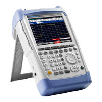
Rohde & Schwarz FSH8 Operating Manual (380 pages)
Spectrum Analyzer
Brand: Rohde & Schwarz
|
Category: Measuring Instruments
|
Size: 8.18 MB
Table of Contents
-
Operating Manual
1
-
Basic Safety Instructions
3
-
Table of Contents
16
-
Documentation Overview
24
-
Conventions Used in the Documentation
25
-
1 Operating the R&S FSH
26
-
Screen Layout and Elements
26
-
Means of Input
27
-
Using the Alphanumeric Keys
28
-
Confirming and Cancelling Entries
29
-
Using the Rotary Knob
29
-
Remote Operation
30
-
Presetting the R&S FSH
31
-
Configuring Measurements
31
-
Configuring the Instrument
32
-
Taking Screenshots
35
-
Saving Events
36
-
Connecting the R&S FSH to a PC
38
-
-
Using the Cursor Keys
30
-
Connecting the R&S FSH in a LAN
39
-
Connecting the R&S FSH in an Existing LAN
42
-
Connecting the R&S FSH Via USB
43
-
Managing Datasets
44
-
-
Saving Datasets
46
-
Restoring Datasets
51
-
Deleting Datasets
53
-
Updating the Firmware
54
-
Installing Firmware Options
54
-
-
-
2 Working with the Measurement Wizard
55
-
Creating a Measurement Set
56
-
Preparing the Measurement
56
-
Uploading Measurement Sets
58
-
Using the Measurement Wizard
59
-
Starting the Measurement Wizard
59
-
Performing a Sequence of Measurements
61
-
Evaluating Results
64
-
-
Measuring Basic Signal Characteristics
65
-
Measuring the Channel Power of Continuously Modulated Signals
66
-
Measuring the Occupied Bandwidth
70
-
Power Measurements on TDMA Signals
74
-
Measuring the Adjacent Channel Leakage Ratio (ACLR)
77
-
Measuring the Spectrum Emission Mask
86
-
Measuring the Harmonic Distortion
89
-
Measuring the am Modulation Depth
91
-
Measuring Spurious Emissions
93
-
-
-
3 Spectrum Analyzer Mode
65
-
Performing Spectrum Measurements
65
-
Working with the Spectrogram Result Display (R&S FSH-K14/ -K15)
96
-
Using Isotropic Antennas
107
-
Configuring Spectrum Measurements
109
-
Configuring the Horizontal Axis
109
-
Configuring the Vertical Axis
113
-
Setting Bandwidths
117
-
Configuring and Triggering the Sweep
120
-
Working with Traces
126
-
Using Markers
131
-
Using Display Lines
140
-
Using Limit Lines
141
-
Working with Channel Tables
144
-
Using Transducer Factors
145
-
-
Unit for Measurements with Transducers
146
-
Setting the Reference Level
146
-
Frequency Range of Transducer
147
-
Data Sets Containing Transducer Factors
147
-
-
-
4 Power Meter
148
-
Using a Power Sensor
148
-
Connecting a Power Sensor
150
-
Performing and Configuring Measurements
151
-
Using a Directional Power Sensor
154
-
-
Connecting a Directional Power Sensor
155
-
Performing and Configuring Measurements
156
-
Using the Internal Power Meter
159
-
Performing Pulse Power Measurements (R&S FSH-K29)
160
-
-
Configuring the Numerical Result Display
163
-
Configuring the Power Vs Time Result Display
163
-
-
5 Interference Analyzer (R&S FSH-K15/ -K16)
167
-
Measuring the Carrier-To-Noise Ratio
169
-
Measuring the Spectrum
169
-
Measuring the Carrier-To-Interference Ratio
170
-
Analyzing Interference Measurements
171
-
Working with Maps
172
-
-
Transferring Maps (R&S FSH-K15 and -K16)
172
-
Transferring Indoor Maps (R&S FSH-K17)
173
-
Displaying Maps
174
-
Measuring Interference
180
-
Collecting Geographic Data (R&S FSH-K15 and -K16)
183
-
Collecting Measurement Data (R&S FSH-K17)
187
-
Analyzing Geographic Data (R&S FSH-K15 and -K16)
190
-
Analyzing Indoor Data (R&S FSH-K17)
191
-
-
6 Network Analyzer Mode
192
-
Configuring the Tracking Generator
194
-
Calibrating Measurements
196
-
Measuring the Transmission
202
-
Performing Scalar Measurements
202
-
Measuring the Reflection
204
-
Performing Vector Measurements (R&S FSH-K42)
206
-
-
Measuring the Transmission
207
-
Measuring the Reflection
210
-
Evaluating the Results
212
-
-
Selecting the Measurement Format
212
-
Configuring the Vertical Axis
220
-
Using Limit Lines
223
-
Using Markers
223
-
Using Trace Mathematics
223
-
Vector Voltmeter (R&S FSH-K45)
224
-
-
Working with Channel Tables
223
-
Calibrating Measurements
225
-
Performing Measurements
226
-
Evaluating the Results
228
-
-
7 Distance-To-Fault Mode (R&S FSH-K41)
229
-
Performing Cable and Antenna Measurements
231
-
Reflection Measurements
231
-
Distance to Fault Measurements
232
-
Spectrum Measurements
232
-
Selecting the Measurement Format
233
-
Calibrating Measurements
235
-
Configuring Cable and Antenna Tests
236
-
-
Selecting the Cable Model
236
-
Configuring the Horizontal Axis
239
-
Configuring the Amplitude Characteristics
241
-
Configuring the Tracking Generator
243
-
Analyzing Measurement Results
244
-
-
Working with Traces
244
-
Using Display and Limit Lines
245
-
-
8 Receiver Mode (R&S FSH-K43)
246
-
Using Markers
245
-
Performing Single Frequency Measurements
247
-
Selecting the Measurement Mode
247
-
Performing Frequency Scans
250
-
Configuring Measurements in Receiver Mode
253
-
-
Selecting Detectors for EMI Measurements
253
-
Selecting the Measurement Bandwidths for EMI Measurements
255
-
Defining the Measurement Time
256
-
Using Limit Lines
257
-
-
9 Digital Modulation Analyzer
258
-
Using Transducers
257
-
Working with Traces
257
-
General Settings in the Result Summary
259
-
General Settings of the Digital Modulation Analyzer
259
-
Trace Mode Selection
262
-
General Result Displays of the Digital Modulation Analyzer
264
-
Measurements on GSM Signals
267
-
-
The Result Summary
268
-
The Burst Power Result Display
272
-
Configuring the Measurement
274
-
Measurements on 3GPP FDD Signals
275
-
-
The Result Summary
276
-
The Code Domain Analyzer
280
-
The Code Domain Channel Table
282
-
Configuring the Measurement
284
-
Measurements on CDMA2000 Signals
288
-
-
The Result Summary
289
-
The Code Domain Analyzer
292
-
The Code Domain Channel Table
294
-
The PN Scanner
296
-
Configuring the Measurement
297
-
Measurements on 1Xev-DO Signals
300
-
The Result Summary
301
-
The PN Scanner
304
-
The Burst Power Result Display
305
-
Configuring the Measurement
306
-
Measurements on TD-SCDMA Signals
307
-
-
The Result Summary
308
-
The Code Domain Analyzer
312
-
The Code Domain Channel Table
314
-
The Sync ID Result Display
316
-
The Time Domain Power Result Display
317
-
Configuring the Measurement
319
-
Measurements on LTE Signals
323
-
-
The Result Summary
324
-
The Result Summary for Carrier Aggregation
330
-
The Constellation Diagram
331
-
The BTS Scanner
333
-
The Resource Allocations Result Display
334
-
Configuring the Measurement
336
-
-
-
10 Menu and Softkey Overview
342
-
General Functions
342
-
General R&S FSH Setup
342
-
File Management
343
-
Operating Mode Selection
343
-
Functions of the Spectrum Analyzer
344
-
-
Measurement Selection
344
-
Frequency Parameters
346
-
Amplitude Parameters
347
-
Bandwidth Selection
347
-
Span Selection
347
-
Sweep Configuration
347
-
Display and Limit Lines
348
-
Markers
348
-
Functions of the Network Analyzer
350
-
-
Trace Functionality
348
-
Frequency Parameters
350
-
Measurement Configuration
350
-
Amplitude Parameters
351
-
Bandwidth Selection
351
-
Span Selection
351
-
Sweep Configuration
351
-
Limit Lines
352
-
Markers
352
-
Functions of the Power Meter
354
-
-
Trace Functionality
352
-
Frequency Parameters
354
-
Power Meter Measurements
354
-
Amplitude Parameters
355
-
Bandwidth Configuration
355
-
Sweep Configuration
355
-
Trace Configuration
356
-
Functions of the Distance-To-Fault Mode
357
-
-
Frequency Parameters
357
-
Measurement Configuration
357
-
Amplitude Parameters
358
-
Bandwidth Selection
358
-
Span Selection
358
-
Sweep Configuration
358
-
Markers
359
-
Functions of the Receiver Mode
360
-
-
Trace Functionality
359
-
Frequency Parameters
360
-
Measurement Configuration
360
-
Span Selection
360
-
Amplitude Parameters
361
-
Bandwidth Selection
361
-
Sweep Configuration
361
-
Trace Functionality
361
-
Markers
362
-
Functions of the Interference Analyzer (Map Mode)
363
-
-
Frequency Parameters
363
-
Measurement Configuration
363
-
Amplitude Parameters
364
-
Bandwidth Selection
364
-
Sweep Configuration
364
-
Trace Functionality
364
-
Functions of the Digital Modulation Analyzer
365
-
-
Measurement Configuration
365
-
Frequency Parameters
367
-
Amplitude Parameters
368
-
Sweep Configuration
368
-
Trace Functionality
369
-
-
11 How a Spectrum Analyzer Works
370
-
Index
376
-
Advertisement

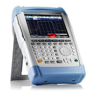
Rohde & Schwarz FSH8 Operating Manual (250 pages)
Spectrum Analyzer
Brand: Rohde & Schwarz
|
Category: Measuring Instruments
|
Size: 8.87 MB
Table of Contents
-
Table of Contents
20
-
Operating the R&S FSH
32
-
Screen Layout and Elements
32
-
Means of Input
33
-
Using the Alphanumeric Keys
33
-
Confirming and Cancelling Entries
34
-
Using the Rotary Knob
34
-
Using the Cursor Keys
35
-
Presetting the R&S FSH
35
-
Taking Screenshots
36
-
Measurement Setup
36
-
Instrument Setup
37
-
Updating the Firmware
39
-
Installing Firmware Options
39
-
Menu and Softkey Overview
40
-
-
General Functions
40
-
General R&S FSH Setup
40
-
File Management
41
-
Operating Mode Selection
41
-
Functions of the Spectrum Analyzer
42
-
-
Measurement Selection
42
-
Frequency Parameters
44
-
Span Selection
44
-
Amplitude Parameters
45
-
Sweep Configuration
45
-
Bandwidth Selection
45
-
Trace Functionality
46
-
Display and Limit Lines
46
-
Markers
46
-
Functions of the Network Analyzer
47
-
-
Measurement Configuration
47
-
Frequency Parameters
48
-
Span Selection
48
-
Amplitude Parameters
48
-
Sweep Configuration
48
-
Bandwidth Selection
49
-
Trace Functionality
49
-
-
Limit Lines
49
-
Markers
50
-
Functions of the Receiver Mode
51
-
-
Measurement Configuration
51
-
Frequency Parameters
51
-
Amplitude Parameters
51
-
Span Selection
52
-
Sweep Configuration
52
-
Bandwidth Selection
52
-
Trace Functionality
52
-
Markers
52
-
Functions of the Power Meter
53
-
-
Power Meter Measurements
53
-
Frequency Parameters
53
-
Amplitude Parameters
54
-
Sweep Configuration
54
-
Functions of the Distance-To-Fault Mode
54
-
-
Measurement Configuration
54
-
Frequency Parameters
55
-
Span Selection
55
-
Amplitude Parameters
55
-
Sweep Configuration
55
-
Bandwidth Selection
56
-
Trace Functionality
56
-
Markers
56
-
Functions of the Digital Modulation Analyzer
57
-
-
Measurement Configuration
57
-
Frequency Parameters
59
-
Amplitude Parameters
59
-
Sweep Configuration
59
-
Trace Functionality
60
-
Spectrum Analyzer Mode
61
-
Performing Spectrum Measurements
61
-
Measuring the Channel Power of Continuously Modulated Signals
61
-
-
Selecting the Standard
62
-
Setting the Reference Level
63
-
Setting the Channel Bandwidth
63
-
Changing the Span
63
-
Measuring the Maximum Channel Power
64
-
Unit for Power Display
64
-
Measuring the Occupied Bandwidth
65
-
-
Selecting a Standard
66
-
Setting the Reference Level
66
-
Setting the Channel Bandwidth
67
-
Defining the Percentage of Occupied Bandwidth
67
-
Changing the Span
68
-
Power Measurements on TDMA Signals
68
-
-
Selecting a Standard
69
-
Setting the Burst Length
70
-
Setting the Reference Level
70
-
Using a Trigger
70
-
Measuring the Adjacent Channel Leakage Ratio (ACLR)
71
-
-
Selecting a Standard
74
-
Configuring the Measurement
75
-
Normalization of Measurement Results
77
-
Displaying Absolute and Relative Results
77
-
Selecting the Reference Channel
78
-
Setting and Checking the Limits
78
-
Measuring the Spectrum Emission Mask
79
-
-
Selecting a Standard
80
-
Optimizing Measurement Settings
81
-
Viewing the Results in a Table
81
-
Measuring the Harmonic Distortion
82
-
-
Defining the Number of Harmonics
83
-
Optimizing the Display of Harmonics
84
-
Activating the Harmonics List
84
-
Measuring the am Modulation Depth
84
-
-
Setting a Threshold
85
-
Optimizing the Settings
85
-
Activating the Marker List
86
-
Working with the Spectrogram Result Display (R&S FSH-K14)
86
-
-
Controlling the Spectrogram Update
87
-
Browsing through the Signal History
88
-
Configuring the Display
89
-
Recording a Spectrogram
91
-
Playback of a Spectrogram
92
-
Using Isotropic Antennas
94
-
Configuring Spectrum Measurements
96
-
-
Configuring the Horizontal Axis
96
-
-
Defining the Center Frequency
96
-
Defining a Frequency Step Size
97
-
Setting a Frequency Offset
97
-
Defining a Start and Stop Frequency
98
-
Setting the Span
98
-
Configuring the Vertical Axis
99
-
-
Setting the Reference Level
99
-
Setting a Display Range
100
-
Selecting the Display Unit
100
-
Setting a Reference Offset
101
-
Setting the RF Attenuation
101
-
Using the Preamplifier
102
-
Setting the Input Impedance
103
-
Using Transducer Factors
103
-
Setting Bandwidths
103
-
-
Setting the Resolution Bandwidth
103
-
Setting the Video Bandwidth
105
-
Configuring and Triggering the Sweep
106
-
-
Setting the Sweep Time
106
-
Selecting the Sweep Mode
107
-
Working with Trigger Functionality
107
-
Working with Traces
110
-
-
Selecting the Trace Mode
110
-
Selecting the Detector
112
-
Working with a Second Trace
114
-
Working with Memory Traces
114
-
Using Trace Mathematics
115
-
Using Markers
115
-
-
Positioning Markers
116
-
Positioning a Delta Marker
117
-
Selecting the Marker Type
118
-
Automatic Positioning of Markers
118
-
Removing Markers
118
-
Using Marker Search Limits
119
-
Using Marker Functions
120
-
Using Display Lines
124
-
Using Limit Lines
124
-
-
Selecting a Limit Line
125
-
Performing Limit Checks
126
-
Working with Channel Tables
127
-
Using Transducer Factors
128
-
Unit for Measurements with Transducers
129
-
Setting the Reference Level
129
-
Frequency Range of Transducer
130
-
Data Sets Containing Transducer Factors
130
-
Working with Power Sensors
131
-
Using a Power Sensor
131
-
-
Connecting a Power Sensor
132
-
Performing and Configuring Measurements
133
-
Using a Directional Power Sensor
136
-
-
Connecting a Directional Power Sensor
137
-
Performing and Configuring Measurements
137
-
Network Analyzer Mode
141
-
Calibrating Measurements
142
-
-
-
Calibration States
143
-
Calibration Methods
144
-
Performing Calibration
146
-
Performing Scalar Measurements
148
-
-
Measuring the Transmission
148
-
Measuring the Reflection
150
-
Performing Vector Measurements (R&S FSH-K42)
151
-
-
Measuring the Transmission
152
-
Measuring the Reflection
153
-
Evaluating the Results
155
-
-
Selecting the Measurement Format
155
-
Working with the Smith Chart
157
-
Working with the Dual Trace Mode
160
-
Configuring the Vertical Axis
161
-
Using Markers
164
-
Working with Channel Tables
164
-
Using Limit Lines
164
-
Using Trace Mathematics
164
-
Vector Voltmeter (R&S FSH-K45)
165
-
-
-
-
Calibrating Measurements
166
-
Performing Measurements
166
-
Performing Reflection Measurements
167
-
Evaluating the Results
168
-
-
Performing Transmission Measurements
167
-
Comparing Results
168
-
Configuring the Vertical Axis
168
-
Distance-To-Fault Mode (R&S FSH-K41)
169
-
Performing Cable and Antenna Measurements
171
-
Reflection Measurements
171
-
Distance to Fault Measurements
172
-
Spectrum Measurements
173
-
Selecting the Measurement Format
173
-
Calibrating Measurements
174
-
-
Selecting the Measurement Format
168
-
Calibration Methods
174
-
Calibration States
174
-
Performing a Full 2-Port Calibration
174
-
Configuring Cable and Antenna Tests
174
-
Selecting the Cable Model
174
-
-
Creating a Cable Model
175
-
Selecting a Predefined Cable Model
175
-
Working with a DTF List
176
-
Configuring the Horizontal Axis
177
-
-
Setting the Frequency Range for DTF Measurements
177
-
Selecting the Cable Length
178
-
Configuring the Vertical Axis
179
-
-
Adjusting the Scale of the Diagram
179
-
Setting the Attenuation
180
-
Using Markers
181
-
Using Display and Limit Lines
181
-
Receiver Mode
182
-
Selecting the Measurement Mode
182
-
-
Performing Single Frequency Measurements
182
-
-
Defining the Receive Frequency
183
-
Customizing the Bargraph Aspects
184
-
Performing Frequency Scans
185
-
-
Defining the Scan Range
186
-
Using Markers
187
-
Configuring Measurements in Receiver Mode
187
-
Selecting Detectors for EMI Measurements
187
-
Selecting the Measurement Bandwidths for EMI Measurements
188
-
Defining the Measurement Time
189
-
Using Transducers
189
-
Digital Modulation Analyzer
190
-
Measurements on 3GPP FDD Signals
195
-
-
The Result Summary
195
-
-
General Settings
196
-
Global Results
197
-
Channel Results
198
-
The Code Domain Analyzer
199
-
-
Diagram Header
200
-
Header Table
200
-
Diagram Area
201
-
The Code Domain Channel Table
201
-
-
Channel Table
202
-
Configuring the Measurement
203
-
-
Global Results
202
-
Header Table
202
-
Specifying the Scrambling Code
203
-
Selecting the Slot and Code Channel
204
-
Setting the Antenna Diversity
204
-
Changing the Code Power
205
-
Performing Fast Measurements
205
-
Measurements on CDMA2000 Signals
206
-
The Result Summary
206
-
-
General Settings
207
-
Global Results
208
-
Channel Results
209
-
The Code Domain Analyzer
209
-
-
Diagram Area
210
-
The Code Domain Channel Table
211
-
-
Header Table and Diagram Header
210
-
Channel Table
211
-
The PN Scanner
212
-
Configuring the Measurement
213
-
-
Global Results
211
-
Header Table
211
-
Changing the Code Order
213
-
Setting the Base Spreading Factor
213
-
Changing the Reference Power
214
-
Selecting the Unit of the Carrier Frequency Error
214
-
Changing the PN Offset
215
-
Synchronizing to a Base Station Using a GPS Receiver
215
-
Measurements on 1Xev-DO Signals
215
-
The Result Summary
216
-
-
General Settings
216
-
Global Results
217
-
Channel Results
218
-
The PN Scanner
218
-
The Burst Power Result Display
219
-
Configuring the Measurement
219
-
-
Changing the PN Offset
219
-
Selecting the Unit of the Carrier Frequency Error
219
-
Synchronizing to a Base Station Using a GPS Receiver
220
-
Measurements on LTE Signals
220
-
The Result Summary
221
-
-
General Settings
221
-
Global Results
222
-
Allocation Summary
223
-
Reference Signal Overview
224
-
The Constellation Diagram
224
-
The Resource Allocations Result Display
226
-
Configuring the Measurement
227
-
-
Selecting the Channel Bandwidth
227
-
Selecting the Cell Identity
228
-
Selecting the Cyclic Prefix
228
-
Selecting the MIMO Configuration
229
-
Selecting the Subframe Configuration for TDD Signals
229
-
Selecting the Synchronization Signal
229
-
Configuring EVM Results
230
-
Saving and Loading Instrument Settings and Measurement Results
232
-
Saving Data Sets
232
-
Quick Naming of Data Sets
234
-
Putting Together a File Name
234
-
Designing a Table
235
-
Loading Measurement Results
235
-
-
Previewing a Dataset
236
-
Loading a Dataset
236
-
Quick Recall of Instrument Settings
236
-
Compiling a Measurement Report
237
-
Deleting Datasets
238
-
How a Spectrum Analyzer Works
240
-
-
-
-
Selecting the Unit of the Carrier Frequency Error
230
-
-
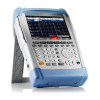
Rohde & Schwarz FSH8 Operating Manual (142 pages)
Handheld Spectrum Analyzer
Brand: Rohde & Schwarz
|
Category: Measuring Instruments
|
Size: 5.44 MB
Table of Contents
-
Operating Manual
3
-
Table of Contents
5
-
1 Putting into Operation
30
-
2 Getting Started
31
-
3 Operation
32
-
Screen Layout
32
-
Screen Layout for Spectrum-Mode Measurements Without Markers
32
-
Screen Layout When the Marker Mode Is Selected
33
-
-
Entering Measurement Parameters
34
-
Entering Values and Texts
34
-
Entering Units
35
-
Tables
36
-
-
-
Menu Overview
36
-
General Settings
37
-
Selection of the Measurement Mode
37
-
Softkeys of the Spectrum Analyzer Mode
38
-
Frequency Entry
38
-
Frequency Span
38
-
Level Settings
38
-
Bandwidth Settings
38
-
Sweep
39
-
Trace Settings
39
-
Limit Lines
39
-
Measurement Functions
39
-
Channel Power
40
-
Occupied Bandwidth
40
-
TDMA Power
40
-
-
Marker
41
-
Marker Position
41
-
-
Softkeys of the Network Analyzer Mode
42
-
Frequency Entry
42
-
Frequency Span
42
-
Level Settings
42
-
Bandwidth Settings
42
-
Sweep
42
-
Trace Settings
43
-
Limit Lines
43
-
Measurement Functions
43
-
Marker
44
-
Marker Position
44
-
-
Softkeys of the Distance to Fault Mode
45
-
Frequency Entry
45
-
Frequency Span
45
-
Level Settings
45
-
Bandwidth Settings
45
-
Sweep
45
-
Trace Settings
46
-
Measurement Functions
46
-
Marker
46
-
Marker Position
46
-
-
Softkeys of the Power Meter Mode
47
-
Frequency Entry
47
-
Level Settings
47
-
Sweep
47
-
-
Measurement Functions
47
-
-
-
-
4 Instrument Functions
48
-
Instrument Default Setup
48
-
Setting the Frequency
48
-
Entering the Center Frequency
49
-
Setting a Frequency Offset
49
-
Entering the Center-Frequency Step Size
50
-
Entering the Start and Stop Frequency
50
-
Working with Channel Tables
51
-
-
Setting the Span
52
-
Setting the Amplitude Parameters
53
-
Setting the Reference Level
54
-
Entering the Display Range
55
-
Entering the Display Unit
56
-
Entering the Reference Offset
56
-
Entering of the RF-Attenuation
56
-
Entering the RF Preamplification
57
-
Entering the Input Impedance
57
-
Selecting a Transducer Factor
57
-
-
Setting the Bandwidths
59
-
Resolution Bandwidth
59
-
Video Bandwidth
60
-
-
Setting the Sweep
62
-
Sweep Time
62
-
Sweep Mode
63
-
Trigger
63
-
-
Trace Settings
65
-
Trace Mode
65
-
Detector
66
-
Trace-Selection
68
-
Trace Memory
69
-
Trace Mathematics
70
-
-
Using the Markers
70
-
Automatic Marker Positioning
72
-
Using more than One Marker at a Time (Multimarker Mode)
74
-
Marker Functions
76
-
Measuring the Noise Power Density
76
-
Measuring the Frequency
77
-
-
AF Demodulation
78
-
-
Using the Display Line
79
-
Using Limit Lines
79
-
Measurements with Limit Lines
81
-
Definition Range of Limit Lines
82
-
Data Sets Containing Limit Lines
82
-
-
Setting and Using the Measurement Functions
82
-
Measuring the Channel Power of Continuously Modulated Signals
82
-
Selecting the Standard
83
-
Setting the Reference Level
84
-
Setting the Channel Bandwidth
84
-
Changing the Span
84
-
Unit for Power Display
86
-
-
Power Measurements on TDMA Signals
86
-
Selecting a Standard
87
-
Setting the Burst Length
87
-
Optimizing the Reference Level
88
-
Power Readout
88
-
Setting the Trigger
88
-
-
Measuring the Occupied Bandwidth
89
-
Selecting a Standard
90
-
Setting the Reference Level
90
-
Setting the Channel Bandwidth
91
-
Entering the Power Percent to Determine the Occupied Bandwidth
91
-
Displaying the Occupied Bandwidth
92
-
Changing the Span
92
-
-
Two-Port Measurements with the Tracking Generator
92
-
Measuring the Transmission of Two-Ports
95
-
Vector Measurement
97
-
Vector Transmission Measurement
99
-
Measuring the Transmission Magnitude
101
-
Measuring the Transmission Phase (Models with Integrated VSWR Bridge Only)
101
-
Supplying DC Voltage to Active Duts (Models with Integrated VSWR Bridge Only)
102
-
Scalar Measurement of Reflection
102
-
Vector Measurement of Reflection
105
-
Measuring the Reflection Magnitude
106
-
Measuring the Reflection Phase
107
-
Simultaneous Measurement of Magnitude and Phase of the Reflection
107
-
Displaying the Reflection in the Smith Chart
108
-
-
Selecting the Calibration Standards
111
-
-
-
Cable Measurements
113
-
Cable Selection
114
-
Selecting the Frequency Range
115
-
Calibrating the Test Setup
116
-
-
Measurements Using the Power Sensor
119
-
Connecting the Power Sensor
119
-
Zeroing the Power Sensor
121
-
Selecting the Unit for the Power Readout
122
-
Setting the Averaging Time
122
-
Taking Additional Loss or Gain into Account
123
-
-
Measuring Forward and Reflected Power
123
-
Zeroing the Power Sensor
126
-
Setting the Power Measurement Weighting
127
-
Selecting the Unit for the Power Readout
127
-
Taking Additional Attenuation into Account
128
-
-
-
Measuring with Transducer Factors
130
-
Unit for Measurements with Transducers
132
-
Reference Level Settings for Measurements with Transducers
132
-
Frequency Range of Transducer
133
-
Data Sets Containing Transducer Factors
133
-
-
Saving and Loading Instrument Settings and Measurement Results
134
-
Saving Results
135
-
Entering a Data Set Name
135
-
Loading Measurement Results
136
-
-
Measurements
137
-
How a Spectrum Analyzer Operates
137
-
Advertisement
Rohde & Schwarz FSH8 Quick Start Manual (77 pages)
Spectrum Analyzer
Brand: Rohde & Schwarz
|
Category: Measuring Instruments
|
Size: 2.81 MB
Table of Contents
-
Table of Contents
3
-
Safety Instructions
6
-
Instrucciones de Seguridad
7
-
Sicherheitshinweise
8
-
Consignes de Sécurité
9
-
Documentation Overview
10
-
Contacting Customer Support
12
-
1 Putting into Operation
13
-
Unpacking the R&S FSH
14
-
Overview of Controls
15
-
Setting up the R&S FSH
16
-
Using the AC Adapter
17
-
Battery Operation
18
-
Battery Maintenance
20
-
Handling
20
-
Storage
20
-
End of Life
21
-
Connectors on the R&S FSH
22
-
RF Input
23
-
Tracking Generator Output
24
-
Power Sensor Port
24
-
Headphone Jack
25
-
AUX Input
25
-
BNC Connectors
26
-
-
Transportation
21
-
BIAS Port 1 / BIAS Port 2
26
-
Ext Trig / Ext Ref
26
-
IF Output
27
-
Mini USB and LAN Ports
28
-
Mechanical Locking Device
28
-
DC Port
29
-
-
USB Port
29
-
SD Card Slot
29
-
Managing Options
30
-
Enabling Options
30
-
Checking Installed Options
30
-
Managing Options with the R&S License Manager
31
-
Configuring the R&S FSH
33
-
-
Configuring the Hardware
34
-
Configuring Antennas
36
-
Using the GPS Receiver
39
-
Configuring Date and Time
41
-
Selecting Regional Attributes
42
-
Configuring the Display
43
-
Configuring Audio Output
44
-
Configuring Power Supply
45
-
Self Alignment
46
-
-
Using a PIN Code
46
-
Resetting the R&S FSH
47
-
Connecting the R&S FSH to a PC
48
-
Connecting the R&S FSH in a LAN
48
-
Connecting the R&S FSH in an Existing LAN
51
-
Connecting the R&S FSH Via USB
52
-
Attenuating the Signal
54
-
Using the Preamplifier
55
-
Measuring CW Signals
56
-
Measuring Harmonics
59
-
Using the Network Analyzer
61
-
-
Calibrating the R&S FSH
62
-
Measuring the Vector Reflection
64
-
Measuring Scalar Transmission
65
-
Using a Power Sensor
66
-
-
Measuring the Power with a Power Sensor
67
-
Measuring Power and Return Loss
69
-
Identifying Cable Faults
71
-
Saving and Recalling Results and Settings
75
-
-
Saving Measurement Results
75
-
Recalling Measurement Results
76
-
Index
77
-
-
-
-
2 Getting Started
53
-
Using the Spectrum Analyzer
54
-
Rohde & Schwarz FSH8 How To Perform (2 pages)
How to perform a signal strength measurement showing the results on the outdoor map From the expert’s desk
Brand: Rohde & Schwarz
|
Category: Measuring Instruments
|
Size: 0.45 MB
Advertisement
Related Products
-
Rohde & Schwarz FSH4
-
Rohde & Schwarz FSH13
-
Rohde & Schwarz FSH20
-
Rohde & Schwarz FSH3
-
Rohde & Schwarz FSH
-
Rohde & Schwarz FSH6
-
Rohde & Schwarz FSH18
-
Rohde & Schwarz FSEK20
-
Rohde & Schwarz FSV3-K6
-
Rohde & Schwarz FSV3000
Rohde & Schwarz Categories
Measuring Instruments
Test Equipment
Portable Generator
Accessories
![]()
Power Supply
More Rohde & Schwarz Manuals
Универсальный портативный анализатор является незаменимым инструментом для выполнения регламентных измерительных задач в полевых условиях.
Прибор представляет собой анализатор спектра, анализатор цепей, анализатор кабелей и антенн, анализатор обнаружения источников помех и измеритель мощности. Наделенный функциями анализатор делает полевые измерения простыми и эффективными. Прочная конструкция и встроенная рукоятка делают прибор идеальным для выполнения любых задач вне помещений.
Функции:
Основная функция FSH8 – это анализ спектра, но в зависимости от установленных опций прибор можно использовать в качестве:
- измерителя мощности,
- кабельного и антенного тестера,
- двухпортового векторного анализатора электрических цепей.
Прибор обеспечивает выполнение трех важнейших функций ВЧ-анализа, необходимых работникам сервисных центров или бригадам, выполняющим пуско-наладочные работы или регламентные работы по техническому обслуживанию.
* Изображения служат только для ознакомления,
см. техническую документацию
15 000 руб.
× 1 =
15 000 руб.
Добавить в корзину 1 шт.
на сумму 1 643 000 руб.
Номенклатурный номер: 9000293601
Артикул: FSH8 (с предусил. и след. генератором)
PartNumber: 1309.6000.18
Страна происхождения: ЧЕХИЯ
Бренд / Производитель: Rohde & Schwarz

Описание
Портативный анализатор спектра R&S®FSH4/8/13/20
Универсальные приборы для мобильного применения
R&S®FSH – это, в первую очередь, анализатор спектра, но в зависимости от установленных опций может выступать в роли измерителя мощности, кабельного и антенного тестера, и двухпортового векторного анализатора электрических цепей. Прибор обеспечивает выполнение трех важнейших функций ВЧ-анализа, необходимых работникам сервисных центров или бригадам, выполняющим пусконаладочные работы или регламентные работы по техническому обслуживанию. Модельный ряд прибор: FSH4 до 3.6 ГГц, FSH8 до 8.0 ГГц, FSH13 до 13.6 ГГц, FSH20 до 20.0 ГГц.
Диапазон частот от 9 кГц до 3.6/8 ГГц и 13.6/20 ГГц
Высокая чувствительность (менее –141 дБмВт (1 Гц), менее –161 дБмВт (1 Гц) с предусилителем)
Малая погрешность измерения (менее 1 дБ)
Полосы разрешения от 1 Гц до 3 МГц. Максимальная полоса демодуляции до 20 МГц (при анализе сигналов LTE)
Измерительные функции для всех основных задач по вводу и обслуживанию передающих систем
ПО R&S®FSH4View для простого документирования результатов измерении
Внутренний следящий генератор и КСВН-мост со встроенным инжектором питания исследуемого устройства по коаксиальной линии
Двухпортовый анализатор цепеи
Легкозаменяемая литиево-ионная батарея на 4.5 часа работы
Сохранение результатов измерений на SD-карте
Сетевой интерфейс и интерфейс USB для дистанционного управления и переноса измеренных данных
Прочный брызгозащищенный корпус для работы в полевых условиях
Простота работы с прибором за счет его легкости (3 кг с батареей) и доступности функциональных клавиш
ПО R&S®FSH WIZARD функция автоматических измерений, для настройки оптимальных параметров и повышения точности измерений.
Особенности
Монтаж и техническое обслуживание передающих (базовых) станций
Измерение мощности импульсных сигналов
Измерение мощности в канале
Анализ передаваемых 3GPP WCDMA сигналов
Измерение расстояния до места повреждения
Двухпортовый векторный анализ цепей
Скалярный анализ цепей
Однопортовое измерение потерь в кабеле
Функция векторного вольтметра
Измерение мощности в диапазоне до 18 ГГц
Направленное измерение мощности в диапазоне до 4 ГГц
Измерение параметров электромагнитного поля
Измерение напряженности поля с помощью направленной антенны
Измерение напряженности поля с помощью ненаправленной антенны
Диагностика при разработке и обслуживании
Общий спектральный анализ
Обнаружение проблем ЭМС
Документирование и дистанционное управление
ПО R&S®FSH4View для документирования результатов измерений
Дистанционное управление по локальной сети или через интерфейс USB
Удобство в работе
Быстрый выбор функций с помощью клавиш и поворотной ручки
Оптимальное считывание результатов измерений в любом положении
Установка частоты с помощью таблиц каналов
Легкодоступные, хорошо защищенные разъемы
Технические параметры
Техническая документация
R&S
®
FSH4/8/13/20
Spectrum Analyzer
Service Manual
1309.6275.82 – 13
The Service Manual describes the following R&S
®
FSH models and options:
● R&S FSH4 (1309.6000.04)
● R&S FSH4 (1309.6000.14)
● R&S FSH4 (1309.6000.24)
● R&S FSH8 (1309.6000.08)
● R&S FSH8 (1309.6000.18)
● R&S FSH8 (1309.6000.28)
● R&S FSH13 (1314.2000.13)
● R&S FSH20 (1314.2000.20)
● R&S FSH4 (1309.6000.54, equivalent to 1309.6000.04)
● R&S FSH4 (1309.6000.64, equivalent to 1309.6000.14)
● R&S FSH4 (1309.6000.74, equivalent to 1309.6000.24)
● R&S FSH8 (1309.6000.58, equivalent to 1309.6000.08)
● R&S FSH8 (1309.6000.68, equivalent to 1309.6000.18)
● R&S FSH8 (1309.6000.78, equivalent to 1309.6000.28)
● R&S FSH13 (1314.2000.63, equivalent to 1314.2000.13)
● R&S FSH13 (1314.2000.73, equivalent to 1314.2000.23)
● R&S FSH20 (1314.2000.70, equivalent to 1314.2000.20)
● R&S FSH20 (1314.2000.30, equivalent to 1314.2000.80)
© 2014 Rohde & Schwarz GmbH & Co. KG
Muehldorfstr. 15, 81671 Munich. Germany
Phone: +49 89 4129-0
Fax: +49 89 4129-12 164
E-mail: [email protected]
Internet: http://www.rohde-schwarz.com
81671 Munich, Germany
Subject to change – Data without tolerance limits is not binding.
R&S
®
is a registered trademark of Rohde & Schwarz GmbH & Co. KG.
Trade names are trademarks of the owners.
The following abbreviations are used throughout this manual:
R&S
®
FSH is abbreviated as R&S FSH.
R&S FSH Table of Contents
Table of Contents
Documentation Overview …………………………………………………………. 3
Conventions Used in the Documentation ………………………………….. 4
1 Performance Test ……………………………………………………………………. 5
1.1
Test Instructions ……………………………………………………………………………………………. 5
1.2
Test Equipment ……………………………………………………………………………………………… 5
1.3
Performance Test R&S FSH ……………………………………………………………………………. 6
1.3.1
Checking the Reference Frequency Accuracy …………………………………………………….. 6
1.3.2
Checking the Level Accuracy and the Frequency Response …………………………………. 7
1.3.3
Checking the Accuracy of the RF Attenuator ……………………………………………………..10
1.3.4
Checking the Accuracy of the IF Gain Setting …………………………………………………….11
1.3.5
Checking the Display Linearity …………………………………………………………………………12
1.3.6
Checking the Phase Noise ………………………………………………………………………………14
1.3.7
Checking the Displayed Average Noise Floor …………………………………………………….15
1.3.8
Checking the Tracking Generator ……………………………………………………………………..16
1.4
Performance Test Report ………………………………………………………………………………17
2 Adjustment ……………………………………………………………………………. 30
2.1
Quick Verification …………………………………………………………………………………………30
2.1.1
Measurement Equipment …………………………………………………………………………………30
2.1.2
Verifying on/off functionality ……………………………………………………………………………..30
2.1.3
Verifying Power and AF Connections ………………………………………………………………..30
2.1.4
Verifying the Display ……………………………………………………………………………………….31
2.1.5
Verifying the Level and Noise …………………………………………………………………………..31
2.1.6
Verifying the Tracking Generator ………………………………………………………………………32
2.2
Adjustment …………………………………………………………………………………………………..33
2.2.1
Adjustment Instructions …………………………………………………………………………………..33
2.2.2
Measurement Equipment and Accessories ………………………………………………………..33
2.2.3
Frequency Response Correction ………………………………………………………………………33
3 Repair ……………………………………………………………………………………. 34
3.1
Instrument Design and Function Description …………………………………………………34
3.1.1
Attenuator ……………………………………………………………………………………………………..35
Service Manual 1309.6275.82 — 13 1
R&S FSH Table of Contents
3.1.2
RF to IF conversion…………………………………………………………………………………………35
3.1.3
Tracking Generator (Models .14/.18/.24/.28/.23/.30 only) …………………………………….36
3.1.4
RF/IF control ………………………………………………………………………………………………….36
3.1.5
Mainboard ……………………………………………………………………………………………………..36
3.1.6
Power and battery management ……………………………………………………………………….36
3.1.7
Processing of measured data, detectors ……………………………………………………………37
3.1.8
Resolution bandwidths (RBW) ………………………………………………………………………….37
3.1.9
Video bandwidths (VBW) …………………………………………………………………………………38
3.1.10
Detectors ……………………………………………………………………………………………………….38
3.1.11
Keypad control ……………………………………………………………………………………………….38
3.1.12
Power sensor …………………………………………………………………………………………………38
3.2
Module Replacement …………………………………………………………………………………….39
3.2.1
Overview of the Modules …………………………………………………………………………………39
3.2.2
Equivalence for Different R&S FSH Part Numbers ……………………………………………..42
3.2.3
Opening the Instrument …………………………………………………………………………………..43
3.2.4
Closing the Instrument …………………………………………………………………………………….46
3.2.5
Spare Part Replacement for Housing Parts ……………………………………………………….46
3.2.6
Replacing Stand Up ………………………………………………………………………………………..50
3.2.7
Spare Part Replacement for Battery Module ………………………………………………………54
3.2.8
Spare Part Replacement for Internal Module ……………………………………………………..56
3.2.9
Spare Part Replacement for Front Module …………………………………………………………57
3.2.10
Spare Part Replacement for Internal Module ……………………………………………………..63
3.2.11
Accessories Spare Parts …………………………………………………………………………………71
4 Firmware Updates / Installing Options …………………………………….. 73
4.1
Installing New R&S FSH Firmware …………………………………………………………………73
4.2
Installing Options………………………………………………………………………………………….75
5 Documents ……………………………………………………………………………. 76
Index …………………………………………………………………………………….. 77
Service Manual 1309.6275.82 — 13 2
R&S FSH Documentation Overview
Documentation Overview
The user documentation for the R&S FSH is divided as follows:
Quick Start Guide
The Quick Start Guide provides basic information on the instrument’s functions.
It covers the following topics:
● overview of all elements of the R&S FSH
● basic information on how to set up the R&S FSH
● information on how to operate the R&S FSH in a network
● instructions on how to perform measurements
Operating Manual
The Operating Manual provides a detailed description on the instrument’s functions
It covers the following topics:
● instructions on how to set up and operate the R&S FSH in its various operating modes
● instructions on how to perform measurements with the R&S FSH
● instructions on how to work with the available software options and applications
● basic information on how a spectrum analyzer works
Service Manual
The Service Manual provides information on maintenance.
It covers the following topics:
● instructions on how to perform a performance test
● instructions on how to repair the R&S FSH including a spare parts list
Release Notes
The release notes describe the installation of the firmware, new and modified functions, eliminated problems, and last minute changes to the documentation. The corresponding firmware version is indicated on the title page of the release notes. The current release notes are provided on the internet.
Internet Site
The internet site at: http://rohde-schwarz.com/product/FSH4/8.html
provides the most up to date information on the R&S FSH. The most recent manuals are available as printable PDF files in the download area.
Also provided for download are firmware updates including the associated release notes, instrument drivers, current data sheets, application notes and image versions.
Service Manual 1309.6275.82 — 13 3
R&S FSH Conventions Used in the Documentation
Conventions Used in the Documentation
The following conventions are used throughout the R&S FSH Service Manual:
Typographical conventions
Convention Description
“Graphical user interface elements” All names of graphical user interface elements both on the screen and on the front and rear panels, such as dialog boxes, softkeys, menus, options, buttons etc., are enclosed by quotation marks.
“KEYS” Key names are written in capital letters and enclosed by quotation marks.
Input
File names, commands, program code
«Links»
«References»
Input to be entered by the user is displayed in italics.
File names, commands, coding samples and screen output are distinguished by their font.
Links that you can click are displayed in blue font.
References to other parts of the documentation are enclosed by quotation marks.
Other conventions
● Remote commands: Remote commands may include abbreviations to simplify input. In the description of such commands, all parts that have to be entered are written in capital letters. Additional text in lower-case characters is for information only.
Service Manual 1309.6275.82 — 13 4
R&S FSH Performance Test
Test Instructions
1 Performance Test
1.1 Test Instructions
● The rated specifications of the analyzer are tested after a warm-up time of at least
15 minutes. Only by adhering to this requirement can compliance with the guaranteed data be ensured.
● Values specified in the following sections are not guaranteed. Only the technical specifications provided on the data sheet are binding.
● The values specified in the data sheet are the guaranteed limits.
● Inputs for settings during measurements are shown as following:
[<KEY>] Press a key on the front panel, eg [SPAN]
[<SOFTKEY>] Press a softkey, e.g. [MARKER -> PEAK].
[<nn unit>] Enter a value and terminate by entering the unit, e.g. [12 kHz].
Successive entries are separated by [:], e.g. [ BW : MANUAL RBW : 3 kHz ].
Item Type of equipment
1 Signal generator
2
3
4
5
6
1.2 Test Equipment
6-dB divider (power splitter)
Power meter
Power sensor
N cable(Short)
50 Ohm termination
Recommended characteristics or features
R&S FSH4: 10 MHz to 3.6 GHz
R&S FSH4: 10 MHz to 8 GHz
R&S FSH13: 10 MHz to 13.6 GHz
R&S FSH20: 10 MHz to 20 GHz
Uncertainty of frequency: 0.1 ppm
Phase noise at 500 MHz:
< -100 dBc/Hz @ 10 kHz
< -110 dBc/Hz @ 100 kHz
< -130 dBc/Hz @ 1 MHz
R&S FSH4: 10 MHz to 3.6 GHz
R&S FSH8: 10 MHz to 8 GHz
R&S FSH13: 10 MHz to 13.6 GHz
R&S FSH20: 10 MHz to 20 GHz
Frequency:
R&S FSH4: 10 MHz to 3.6 GHz
R&S FSH8: 10 MHz to 8 GHz
R&S FSH13: 10 MHz to 13.6 GHz
R&S FSH20: 10 MHz to 20 GHz
RSS ≤ 0.8%
Meter Noise ≤ 20 pW
Attenuation < 1 dB to 8 GHz
Recommended model
R&S SMT06
R&S SMR20
Weinschel 1870A
Agilent 11667
R&S NRP
R&S NRP-Z21
R&S NRP-Z31
9 kHz to 20 GHz
Return loss ≤ -10 dB
R&S order no Application
1039.2000.06
1104.0002.20
Frequency response
Frequency accuracy of reference oscillator
Frequency response
1143.8500.02 Frequency response
1137.6000.02
1169.2400.02
Frequency response
Tracking generator output level
Noise display
Service Manual 1309.6275.82 — 13 5
R&S FSH Performance Test
Performance Test R&S FSH
1.3 Performance Test R&S FSH
1.3.1 Checking the Reference Frequency Accuracy
Test equipment: Signal generator (see » Test Equipment «, item 1)
Test setup:
►
Connect the signal generator to the RF input of the R&S FSH.
Signal generator settings:
Frequency:
Level:
1 GHz
-4 dBm
Determine the output power of the signal generator with the power meter. Adjust the output power of the generator until the power meter shows -10 dBm.
R&S FSH settings: — [ PRESET ]
— [ FREQ : 1 GHz ]
— [ SPAN : 100 kHz ]
— [ BW : MANUAL RBW : 300 kHz ]
Measurement:
— [ AMPT: 0 dBm ]
— [
MARKER : Marker Function: Frequency Count ]
► Read out the frequency value (Count:) of the marker.
Nominal frequency: 1.0 GHz
Refer to » Performance Test Report » for tolerances.
Adjustment of the reference oscillator
The frequency of the reference oscillator can be adjusted by means of a service
function (refer to » Adjustment «).
Service Manual 1309.6275.82 — 13 6
R&S FSH Performance Test
Performance Test R&S FSH
1.3.2 Checking the Level Accuracy and the Frequency Response
Test equipment: Signal generator (see » Test Equipment «, item 1)
Power meter (see » Test Equipment «, item 3)
Power sensor (see » Test Equipment «, item 4)
6-dB power splitter (see » Test Equipment «, item 2)
1.3.2.1 Determining the Level Accuracy at 100 MHz
Test setup:
Evaluation:
► Connect the power sensor (item 4) to the power meter and execute function
‘ZERO’ while there is no signal applied to the power sensor.
► Connect the RF output of the signal generator to the input of the divider.
► Connect output 1 of the divider to the power sensor / power meter.
► Connect output 2 of the divider to the RF input of the R&S FSH
Signal generator settings:
Frequency
Level
100 MHz
6 dBm
► Determine the output power of the signal generator with the power meter. Adjust the output power of the generator until the power meter shows 0 dBm.
R&S FSH settings: — [ PRESET ]
— [
FREQ : 100 MHz ]
— [ AMPT: 0 dBm ]
— [ SPAN : 100 kHz ]
— [ BW : MANUAL RBW : 10 kHz ]
— [ SWEEP : Manual SWP Time : 5s]
— [
TRACE : DETECTOR : RMS ]
► Set the marker to the peak of the signal.
— [ MKR-> : Set to Peak ]
The difference between the signal levels measured with the power meter and the level reading of the marker reflects the absolute level error of the R&S FSH. It can be calculated as:
Level error
100 MHz
= L — L powermeter
Service Manual 1309.6275.82 — 13 7
R&S FSH Performance Test
Performance Test R&S FSH
1.3.2.2 Checking the Frequency Response
Test setup:
For the measurement of the frequency response, the value at 100 MHz for each reference level setting is used as the reference. For reference level and RF attenuator please refer to the settings which are indicated in the chapter “performance test report”!
► Connect the RF output of the signal generator to the input of the divider.
► Connect output 1 of the divider to the power sensor / power meter.
► Connect output 2 of the divider to the RF input of the SA..
Frequency
Level
{f in
}
-4 dBm
Signal generator settings:
Refer to » Performance Test Report » for values of Ref_Lev and f
in
.
► Determine the output power of the signal generator with the power meter. Adjust the output power of the generator until the power meter shows:
-25 dBm ± 0.2 dB
-15 dBm ± 0.2 dB
-5 dBm ± 0.2 dB
0 dBm ± 0.2 dB
-30 dBm ± 0.2 dB
R&S FSH settings: — [ PRESET ]
— [ AMPT : Ref_Lev ]
— [ SPAN : 100 kHz ]
— [
BW : MANUAL RBW : 10 kHz ] for RF_Att = 5 dB (Preamp Off) for RF_Att = 10 dB (Preamp Off) for RF_Att = 20 dB (Preamp Off) for RF_Att = 30 dB (Preamp Off) for RF_Att = 0 dB (Preamp On)
— [ SWEEP : Manual SWP Time : 1s ]
— [ TRACE : DETECTOR : RMS ]
— [ FREQ : CENTER : {f in
} ]
The frequency response of the RF preamplifier has to be checked also. To switch it on, enter:
Reference measurement:
— [ SETUP : RF Att / Amp / Imp: Preamp On ]
To avoid overdriving the preamplifier the output power of the signal generator shall be reduced to -30 dBm at the RF input of the R&S FSH during this measurement.
► Determine signal level L powermeter
.
► Set the marker to the peak of the signal.
— [ MKR-> : SET TO PEAK ]
► The signal level L is displayed by the level reading of the marker.
Ref
100MHz
= L
— L powermeter
Service Manual 1309.6275.82 — 13 8
R&S FSH Performance Test
Performance Test R&S FSH
Measurement
Signal generator settings:
Power meter settings:
Frequency {f in
}
Refer to “ Performance Test Report ” for values of {f
in
}.
Determine the signal level L powermeter
. To achieve higher accuracy, compensating the frequency response of the power sensor is recommended.
R&S FSH settings: — [ FREQ : {f in
} ]
Refer to table under “ Performance Test Report ” for values of {f
in
}.
► Set the marker to the peak of the signal.
Evaluation:
— [ MKR-> : SET TO PEAK ]
The signal level L is displayed by the level reading of the marker.
The frequency response can be calculated as:
► Frequency response = L — L powermeter
— Ref
100 MHz
Service Manual 1309.6275.82 — 13 9
R&S FSH Performance Test
1.3.3 Checking the Accuracy of the RF Attenuator
Performance Test R&S FSH
Test principle: The RF attenuator of the R&S FSH can be switched from 0 to 40 dB in 5 dB increments.
Test equipment: Signal generator (refer to » Test Equipment «, item 1)
Test setup:
Frequency
Maximum level
100 MHz
≥ 6 dBm
► Connect the RF output of the signal generator to the input of the divider.
► Connect output 1 of the divider to the power sensor / power meter.
► Connect output 2 of the divider to the RF input of the R&S FSH.
Signal generator settings:
Frequency
Level
100 MHz
-14 dBm
Determine the output power of the signal generator with the power meter. Adjust the output power of the signal generator until the power meter shows -20 dBm ± 0.2 dB.
R&S FSH settings: — [ PRESET ]
— [ FREQ : 100 MHz ]
— [ SPAN : 100 kHz ]
— [
BW : MANUAL RBW : 10 kHz ]
— [ BW : MANUAL VIDEO BW : 30 kHz ]
— [ TRACE : DETECTOR : RMS ]
— [ AMPT: -10 dBm ]
— [ AMPT: RF Att Amp / Imp: RF attenuation Man: 0 dB ]
Reference measurement:
► Set the marker to the peak of the signal.
[ MKR-> : SET TO PEAK ]
The signal level L is displayed by the level reading of the marker.
Ref
(0 dB)
= L
— L powermeter
Measurement
Signal generator settings
Frequency
Level
100 MHz
RF Att – 24 dB
Refer to » Performance Test Report » for values of {RF Att}.
► Determine the output power of the signal generator with the power meter. Adjust the output power of the generator until the power meter shows the level:
-20 dBm ± 0.2 dB
-15 dBm ± 0.2 dB
-5 dBm ± 0.2 dB
0 dBm ± 0.2 dB
0 dBm ± 0.2 dB for RF_Att = 0 dB for RF_Att = 5 dB for RF_Att = 10 dB for RF_Att = 20 dB for RF_Att = 30 dB
Service Manual 1309.6275.82 — 13 10
R&S FSH
R&S FSH settings: — [
AMPT: RF Att Amp / Imp: RF attenuation Man: 0 dB ]
— [ MKR-> : SET TO PEAK ]
Evaluation: The signal level L is displayed by the level reading of the marker.
The difference between the level inaccuracy of the R&S FSH and Ref
0dBm
RF-Att) is the uncertainty of the RF attenuation:
(at 10 dB
RF Att accuracy
= (L — L powermeter
) – Ref
(0 dB)
Performance Test
Performance Test R&S FSH
1.3.4 Checking the Accuracy of the IF Gain Setting
Test principle: The R&S FSH4 and R&S FSH8 do not have any switchable IF gain. A change in reference level is only a graphical shift on the display. Therefore no measurement is needed to verify the specified accuracy.
Service Manual 1309.6275.82 — 13 11
R&S FSH Performance Test
Performance Test R&S FSH
1.3.5 Checking the Display Linearity
Test equipment: Signal generator (refer to » Test Equipment «, item 1)
Power meter (refer to » Test Equipment «, item 3)
Test setup:
Power sensor (refer to » Test Equipment «, item 4)
6-dB power splitter (refer to » Test Equipment «, item 2)
► Connect the power sensor (item 4) to the power meter and execute function
‘ZERO’ when there is no signal applied to the power sensor.
► Connect the RF output of the signal generator to the input of the divider.
► Connect output 1 of the divider to the power sensor / power meter.
1st Measurement
► Connect output 2 of the divider to the RF input of the R&S FSH.
0 dB to 30 dB below reference level
Signal generator settings:
Frequency
Level
100 MHz
+ 6 dBm
► Determine the output power of the signal generator with the power meter. Adjust the output power of the generator until the power meter shows 0 dBm.
R&S FSH settings: — [ PRESET ]
— [
AMPT: 0 dBm ]
— [ AMPT: RF Att Amp / Imp: RF attenuation Man: 20 dB ]
— [ FREQ: 100 MHz ]
— [ SPAN : 10 kHz ]
— [ Manual RBW : 1 kHz ]
— [
Manual VBW : 3 kHz ]
Reference measurement:
— [ SWEEP: Manual SWP Time : 1 s ]
— [ TRACE : DETECTOR : RMS ]
► Set the marker to the peak of the signal.
Signal generator settings:
— [ MKR-> : SET TO PEAK ]
► The signal level L is displayed by the level reading of the marker.
Ref
(0dB)
= L
— L powermeter
Frequency 100 MHz
Level Sig_Lev + 6 dB
Refer to » Performance Test Report » for values of {Sig_Lev}.
► Determine the output power of the signal generator with the power meter. Adjust the output power of the generator until the power meter shows the value of
{Sig_Lev}.
Service Manual 1309.6275.82 — 13 12
R&S FSH Performance Test
Performance Test R&S FSH
Evaluation: ► The signal level L is displayed by the level reading of the marker.
The difference between the level inaccuracy of the R&S FSH and Ref
0dBm uncertainty of the display linearity:
is the
Linearity uncertainty
= (L — L powermeter
) – Ref
(0dB)
2nd Measurement
30 dB to 50 dB below reference level
Because the sensitivity of the power meter is limited, the internal RF attenuator of the
R&S FSH is used to increase the dynamic range of the input signal.
R&S FSH settings: — [ AMPT: RF Att Amp / Imp: RF attenuation Man: 40 dB ]
Signal generator settings:
Frequency
Level
100 MHz
— 4 dBm
► Determine the output power of the signal generator with the power meter. Adjust the output power of the generator until the power meter shows Sig_Lev ± 0.2 dB.
Reference measurement:
► Set the marker to the peak of the signal.
— [ MKR-> : SET TO PEAK ]
The signal level L is displayed by the level reading of the marker.
With the result of the 1 st
linearity measurement, a new correction factor is to be calculated. “Linearity uncertainty
(-30dB)” is the measured uncertainty of the R&S FSH linearity at 30 dB below reference level.
Signal generator settings:
Ref
(20dB)
= (L — L powermeter
) – Linearity uncertainty
(-30dB)
Frequency
Level
100 MHz
Sig_Lev + 6 dB
Evaluation:
Refer » Performance Test Report » for values of {Sig_Lev}.
► Determine the output power of the signal generator with the power meter. Adjust the output power of the generator until the power meter shows the value Sig_Lev
± 0.2 dB.
The signal level L is displayed by the level reading of the marker.
The difference between the level inaccuracy of the R&S FSH and Ref
20dBm uncertainty of the display linearity:
is the
Linearity uncertainty
= (L — L powermeter
) – Ref
(20dB)
Service Manual 1309.6275.82 — 13 13
R&S FSH Performance Test
Performance Test R&S FSH
1.3.6 Checking the Phase Noise
Test equipment: Signal generator (refer to » Test Equipment «, item 1)
Frequency 500 MHz
Level -4 dBm
Phase noise at 500 MHz:
< -105 dBc (1Hz) @ 10 kHz
< -115 dBc (1Hz) @ 100 kHz
< -130 dBc (1Hz) @ 1 MHz
► Connect the RF output of the signal generator to the RF input of the R&S FSH. Test setup:
R&S FSH settings: Frequency
Level
— [ PRESET ]
— [ FREQ : 500 MHz ]
500 MHz
0 dBm
— [ AMPT : -10 dBm ]
— [
AMPT: RF Att Amp / Imp: RF attenuation Man: 0dB ]
— [ SPAN : 10 kHz ]
— [ Manual RBW : 1 kHz ]
— [ Manual RBW : 1 kHz ]
— [ SWEEP: Manual SWP Time : 500 ms ]
— [
TRACE : DETECTOR : SAMPLE ]
— [ TRACE : Trace Mode: Average 10]
— Marker to peak
Measurement at several Offsets
Evaluation:
— [ MKR-> : SET TO PEAK ]
— Readout marker level L ref
and marker frequency f ref
— [
FREQ : f ref
– {Offset} ] with Offset ={30 kHz, 100 kHz, 1 MHz}
— [ MKR-> : SET TO f ref
– {Offset} ]
— Readout marker level L
Offset
The phase noise will be calculated with:
PN
Offset
= (L
Offset
— L ref
– 30dB) dBc (1 Hz)
Service Manual 1309.6275.82 — 13 14
R&S FSH Performance Test
1.3.7 Checking the Displayed Average Noise Floor
Performance Test R&S FSH
Test equipment: 50-Ω termination (refer to » Test Equipment «, item 6)
Test setup: ► Terminate the RF input of the R&S FSH with 50 Ω
R&S FSH settings: — [
PRESET ]
— [ SPAN : Zero Span ]
— [ BW: Manual RBW : 1 kHz ]
— [ BW: Manual VBW : 10 Hz ]
— [ SWEEP : Manual SWP Time : 600ms]
— [
TRACE : Trace Mode: Average 12]
— [ TRACE : DETECTOR : SAMPLE ]
— [ AMPT : -40 dBm ]
— [ FREQ : {f n
} ]
Refer to » Performance Test Report » for values of f
n
.
R&S FSH settings for the measurement of the displayed average noise floor with preamplifier = ON :
— [
AMPT: RF Att Amp / Imp: PREAMP : ON ]
— [ FREQ : {f n
} ]
Refer to » Performance Test Report » for values of f
n
.
Measurement:
Evaluation:
► Read out the marker level.
The displayed average noise floor is displayed by the level reading of the marker.
Service Manual 1309.6275.82 — 13 15
R&S FSH Performance Test
Performance Test R&S FSH
1.3.8 Checking the Tracking Generator
Test equipment: N cable
Test setup: ► Connect both ports directly with the N cable.
R&S FSH settings:
— [ PRESET ]
— [ MODE: Network Analyzer]
— [ AMPT: RF Att Amp / Imp: RF attenuation Man: 10dB ]
— [ AMPT : TG Output Attenuation: {TG_Att} ]
— [ MEAS : Result Display: {Transmission Rev / Transmission Fwd} ]
— [
MKR->: Set to Peak ]
— [ MKR-> : Set to Minimum ]
► Determine whether the maximum and the minimum value are within the upper and lower functional limit.
The functional limits depend on the R&S FSH model.
Model .14/.18:
Lower functional limit: -10 dB
Upper funtional limit: 10 dB
Model .24/.28
Lower functional limit: -5 dB
Upper functional limit: 5 dB
► Perform the test with the following values of TG_Att:
10 dB, 11 dB, 12 dB, 16 dB, 18 dB
Note:
This test is a functional test only, which makes sure that the tracking generator is working properly. The test result is therefore not included in the performance test report.
Service Manual 1309.6275.82 — 13 16
R&S FSH
1.4 Performance Test Report
Performance Test
Performance Test Report
ROHDE&SCHWARZ
Measurand
Spectrum Analyzer R&S FSH
Model
Order number
Serial number:
Date:
Person responsible:
Signature:
For nominal data and limit values refer to the data sheet supplied with the instrument.
Frequency accuracy (reference oscillator)
Base unit
Specified min. value
0.999998
-0.3
Measured value
__________
__________
1309.6000.04/08/14/18/24/28
1314.2000.13/20/23/30
Specified max. value
1.000002
+0.3
Unit
GHz dB at 100 MHz with
Ref_Lev = 0 dBm
Frequency response (f resp
)
with RF Att = 5 dB
Ref_Lev = -20 dBm
10 MHz
100 MHz
500 MHz
1000 MHz
1500 MHz
2000 MHz
2500 MHz
3000 MHz
3500 MHz
R&S FSH8 / R&S FSH13 / R&S FSH20:
4000 MHz
4500 MHz
5000 MHz
-1
-1
-1
-1
-1
-1
—
-1
-1
-1.5
-1.5
-1.5
__________
Reference
__________
__________
__________
__________
__________
__________
__________
__________
__________
__________
+1
+1
+1
+1
+1
+1
—
+1
+1
+1.5
+1.5
+1.5 dB dB dB dB dB dB dB dB dB dB dB
Service Manual 1309.6275.82 — 13 17
R&S FSH
Measurand
14500 MHz
15000 MHz
15500 MHz
16000 MHz
16500 MHz
17000 MHz
17500 MHz
18000 MHz
18500 MHz
19000 MHz
19500 MHz
19900 MHz
5500 MHz
6000 MHz
7000 MHz
7500 MHz
7990 MHz
R&S FSH13 / R&S FSH20:
8010 MHz
8500 MHz
9000 MHz
9500 MHz
10000 MHz
10500 MHz
11000 MHz
12500 MHz
13000 MHz
13590 MHz
R&S FSH20:
13610 MHz
14000 MHz
Service Manual 1309.6275.82 — 13
-1.5
-1.5
-1.5
-1.5
-1.5
-1.5
-1.5
-1.5
-1.5
-1.5
-1.5
-1.5
-1.5
-1.5
-1.5
-1.5
-1.5
-1.5
-1.5
-1.5
-1.5
-1.5
-1.5
-1.5
Specified min. value
-1.5
-1.5
-1.5
-1.5
-1.5
-1.5
Measured value
__________
__________
__________
__________
__________
__________
__________
__________
__________
__________
__________
__________
__________
__________
__________
__________
__________
__________
__________
__________
__________
__________
__________
__________
__________
__________
__________
__________
__________
__________
Performance Test
Performance Test Report
Unit
+1.5
+1.5
+1.5
+1.5
+1.5
+1.5
+1.5
+1.5
+1.5
+1.5
+1.5
+1.5
+1.5
+1.5
+1.5
+1.5
+1.5
+1.5
+1.5
+1.5
+1.5
+1.5
+1.5
+1.5
Specified max. value
+1.5
+1.5
+1.5
+1.5
+1.5
+1.5 dB dB dB dB dB dB dB dB dB dB dB dB dB dB dB dB dB dB dB dB dB dB dB dB dB dB dB dB dB dB
18
R&S FSH
Measurand
Frequency response (f resp
)
with RF Att = 10 dB
Ref_Lev = -10 dBm
10 MHz
100 MHz
500 MHz
1000 MHz
1500 MHz
2000 MHz
2500 MHz
3000 MHz
3500 MHz
R&S FSH8 / R&S FSH13 / R&S FSH20
4000 MHz
4500 MHz
9000 MHz
9500 MHz
10000 MHz
10500 MHz
11000 MHz
12500 MHz
13000 MHz
13590 MHz
5000 MHz
5500 MHz
6000 MHz
7000 MHz
7500 MHz
7990 MHz
R&S FSH13 / R&S FSH20:
8010 MHz
8500 MHz
Specified min. value
-1.5
-1.5
-1.5
-1.5
-1.5
-1.5
-1.5
-1.5
-1.5
-1.5
-1.5
-1.5
-1.5
-1.5
-1.5
-1.5
-1.5
-1.5
-1
-1
-1
-1
-1
-1
-1
—
-1
Measured value
__________
__________
__________
__________
__________
__________
__________
__________
__________
__________
__________
__________
__________
__________
__________
Reference
__________
__________
__________
__________
__________
__________
__________
__________
__________
__________
__________
Performance Test
Performance Test Report
Unit Specified max. value
+1.5
+1.5
+1.5
+1.5
+1.5
+1.5
+1.5
+1.5
+1.5
+1.5
+1.5
+1.5
+1.5
+1.5
+1.5
+1.5
+1.5
+1.5
+1
+1
+1
+1
+1
+1
+1
—
+1 dB dB dB dB dB dB dB dB dB dB dB dB dB dB dB dB dB dB dB dB dB dB dB dB dB dB
Service Manual 1309.6275.82 — 13 19
R&S FSH
Measurand
R&S FSH20:
13610 MHz
14000 MHz
14500 MHz
15000 MHz
15500 MHz
16000 MHz
16500 MHz
17000 MHz
17500 MHz
18000 MHz
18500 MHz
19000 MHz
19500 MHz
19900 MHz
Frequency response (f resp
)
with RF Att = 20 dB
Ref_Lev = 0 dBm
10 MHz
100 MHz
500 MHz
1000 MHz
1500 MHz
2000 MHz
2500 MHz
3000 MHz
3500 MHz
R&S FSH8 / R&S FSH13 / R&S FSH20:
4000 MHz
4500 MHz
5000 MHz
5500 MHz
6000 MHz
-1.5
-1.5
-1.5
-1.5
-1.5
-1.5
-1.5
-1.5
-1.5
Specified min. value
-1.5
-1.5
-1.5
-1.5
-1.5
-1
-1.5
-1.5
-1.5
-1.5
-1.5
-1
-1
-1
-1
-1
—
-1
-1
Measured value
__________
__________
__________
__________
__________
__________
__________
__________
__________
__________
__________
__________
__________
__________
__________
Reference
__________
__________
__________
__________
__________
__________
__________
__________
__________
__________
__________
__________
+1
+1.5
+1.5
+1.5
+1.5
+1.5
+1
+1
+1
+1
+1
—
+1
+1
Performance Test
Performance Test Report
Unit
+1.5
+1.5
+1.5
+1.5
+1.5
+1.5
+1.5
+1.5
+1.5
Specified max. value
+1.5
+1.5
+1.5
+1.5
+1.5 dB dB dB dB dB dB dB dB dB dB dB dB dB dB dB dB dB dB dB dB dB dB dB dB dB dB dB
Service Manual 1309.6275.82 — 13 20
R&S FSH
Measurand
14500 MHz
15000 MHz
15500 MHz
16000 MHz
16500 MHz
17000 MHz
17500 MHz
18000 MHz
18500 MHz
19000 MHz
19500 MHz
19900 MHz
7000 MHz
7500 MHz
7990 MHz
R&S FSH13 / R&S FSH20:
8010 MHz
8500 MHz
9000 MHz
9500 MHz
10000 MHz
10500 MHz
11000 MHz
12500 MHz
13000 MHz
13590 MHz
R&S FSH20:
13610 MHz
14000 MHz
-1.5
-1.5
-1.5
-1.5
-1.5
-1.5
-1.5
-1.5
-1.5
-1.5
-1.5
-1.5
-1.5
-1.5
-1.5
-1.5
-1.5
-1.5
-1.5
-1.5
-1.5
-1.5
Specified min. value
-1.5
-1.5
-1.5
-1.5
-1.5
Measured value
__________
__________
__________
__________
__________
__________
__________
__________
__________
__________
__________
__________
__________
__________
__________
__________
__________
__________
__________
__________
__________
__________
__________
__________
__________
__________
__________
Performance Test
Performance Test Report
Unit
+1.5
+1.5
+1.5
+1.5
+1.5
+1.5
+1.5
+1.5
+1.5
+1.5
+1.5
+1.5
+1.5
+1.5
+1.5
+1.5
+1.5
+1.5
+1.5
+1.5
+1.5
+1.5
Specified max. value
+1.5
+1.5
+1.5
+1.5
+1.5 dB dB dB dB dB dB dB dB dB dB dB dB dB dB dB dB dB dB dB dB dB dB dB dB dB dB dB
Service Manual 1309.6275.82 — 13 21
R&S FSH
Measurand
Frequency response (f resp
)
with RF Att = 30 dB
Ref_Lev = +5 dBm
10 MHz
100 MHz
500 MHz
1000 MHz
1500 MHz
2000 MHz
2500 MHz
3000 MHz
3500 MHz
9000 MHz
9500 MHz
10000 MHz
10500 MHz
11000 MHz
12500 MHz
13000 MHz
13590 MHz
R&S FSH8 / R&S FSH13 / R&S FSH20:
4000 MHz
4500 MHz
5000 MHz
5500 MHz
6000 MHz
7000 MHz
7500 MHz
7990 MHz
R&S FSH13 / R&S FSH20:
8010 MHz
8500 MHz
Specified min. value
-1.5
-1.5
-1.5
-1.5
-1.5
-1.5
-1.5
-1.5
-1.5
-1.5
-1.5
-1.5
-1.5
-1.5
-1.5
-1.5
-1.5
-1.5
-1
-1
-1
-1
-1
—
-1
-1
-1
Measured value
__________
__________
__________
__________
__________
__________
__________
__________
__________
__________
__________
__________
__________
__________
__________
__________
__________
__________
__________
Reference
__________
__________
__________
__________
__________
__________
__________
Performance Test
Performance Test Report
Unit Specified max. value
+1.5
+1.5
+1.5
+1.5
+1.5
+1.5
+1.5
+1.5
+1.5
+1.5
+1.5
+1.5
+1.5
+1.5
+1.5
+1.5
+1.5
+1.5
+1
+1
+1
+1
+1
—
+1
+1
+1 dB dB dB dB dB dB dB dB dB dB dB dB dB dB dB dB dB dB dB dB dB dB dB dB dB dB
Service Manual 1309.6275.82 — 13 22
R&S FSH
Measurand
R&S FSH20:
13610 MHz
14000 MHz
14500 MHz
15000 MHz
15500 MHz
16000 MHz
16500 MHz
17000 MHz
17500 MHz
18000 MHz
18500 MHz
19000 MHz
19500 MHz
19900 MHz
Frequency response (f resp
)
with PreAmp = ON
RF Att = 0 dB
Ref_Lev = -30 dBm
10 MHz
100 MHz
500 MHz
1000 MHz
1500 MHz
2000 MHz
2500 MHz
3000 MHz
3500 MHz
R&S FSH8 / R&S FSH13 / R&S FSH20:
4000 MHz
4500 MHz
5000 MHz
5500 MHz
-1.5
-1.5
-1.5
-1.5
-1.5
-1.5
-1.5
-1.5
-1.5
Specified min. value
-1.5
-1.5
-1.5
-1.5
-1.5
-1.5
-1.5
-1.5
-1.5
-1
-1
-1
-1
-1
-1
-1
—
-1
Measured value
__________
__________
__________
__________
__________
__________
__________
__________
__________
__________
__________
__________
__________
__________
__________
Reference
__________
__________
__________
__________
__________
__________
__________
__________
__________
__________
__________
+1.5
+1.5
+1.5
+1.5
+1
+1
+1
+1
+1
+1
+1
—
+1
Performance Test
Performance Test Report
Unit
+1.5
+1.5
+1.5
+1.5
+1.5
+1.5
+1.5
+1.5
+1.5
Specified max. value
+1.5
+1.5
+1.5
+1.5
+1.5 dB dB dB dB dB dB dB dB dB dB dB dB dB dB dB dB dB dB dB dB dB dB dB dB dB dB
Service Manual 1309.6275.82 — 13 23
R&S FSH
Measurand
14000 MHz
14500 MHz
15000 MHz
15500 MHz
16000 MHz
16500 MHz
17000 MHz
17500 MHz
18000 MHz
18500 MHz
19000 MHz
19500 MHz
19900 MHz
6000 MHz
7000 MHz
7500 MHz
7990 MHz
R&S FSH13 / R&S FSH20:
8010 MHz
8500 MHz
9000 MHz
9500 MHz
10000 MHz
10500 MHz
11000 MHz
12500 MHz
13000 MHz
13590 MHz
R&S FSH20:
13610 MHz
-1.5
-1.5
-1.5
-1.5
-1.5
-1.5
-1.5
-1.5
-1.5
-1.5
-1.5
-1.5
-1.5
-1.5
-1.5
-1.5
-1.5
-1.5
-1.5
-1.5
-1.5
-1.5
-1.5
Specified min. value
-1.5
-1.5
-1.5
-1.5
-1.5
Measured value
__________
__________
__________
__________
__________
__________
__________
__________
__________
__________
__________
__________
__________
__________
__________
__________
__________
__________
__________
__________
__________
__________
__________
__________
__________
__________
__________
__________
Performance Test
Performance Test Report
Unit
+1.5
+1.5
+1.5
+1.5
+1.5
+1.5
+1.5
+1.5
+1.5
+1.5
+1.5
+1.5
+1.5
+1.5
+1.5
+1.5
+1.5
+1.5
+1.5
+1.5
+1.5
+1.5
+1.5
Specified max. value
+1.5
+1.5
+1.5
+1.5
+1.5 dB dB dB dB dB dB dB dB dB dB dB dB dB dB dB dB dB dB dB dB dB dB dB dB dB dB dB dB
Service Manual 1309.6275.82 — 13 24
R&S FSH
Measurand
3999 MHz
4499 MHz
4999 MHz
5499 MHz
5999 MHz
6499 MHz
6999 MHz
7499 MHz
7999 MHz
Attenuator accuracy
RF_Att / Ref_Lev
0 dB / -10 dBm
5 dB / 0 dBm
10 dB / 0 dBm
20 dB / 10 dBm
30 dB / 15 dBm
Displayed average noise floor (f in 1 Hz bandwidth noise
)
9 kHz (models 04/14/08/18 only)
9 kHz (models 13/20)
100 kHz
1 MHz
10.1 MHz
499 MHz
999 MHz
1499 MHz
1999 MHz
2499 MHz
2999 MHz
3599 MHz
R&S FSH8 / R&S FSH13 / R&S FSH20:
3601 MHz
Specified min. value
-0.3
-0.3
-0.3
—
-0.3
—
—
—
—
—
—
—
—
—
—
—
—
—
—
—
—
—
—
—
—
—
—
Measured value
Ref
__________
__________
__________
__________
__________
__________
__________
__________
__________
__________
__________
__________
__________
__________
__________
__________
__________
__________
__________
__________
__________
__________
__________
__________
__________
__________
-142
-142
-142
-141
-141
-138
-138
-138
-108
-96
-115
-136
-141
-141
-141
-142
-140
-140
-140
-136
-136
-136
Performance Test
Performance Test Report
Unit Specified max. value
+0.3
+0.3
+0.3
—
+0.3 dB dB dB dB dBm (1 Hz) dBm (1 Hz) dBm (1 Hz) dBm (1 Hz) dBm (1 Hz) dBm (1 Hz) dBm (1 Hz) dBm (1 Hz) dBm (1 Hz) dBm (1 Hz) dBm (1 Hz) dBm (1 Hz) dBm (1 Hz) dBm (1 Hz) dBm (1 Hz) dBm (1 Hz) dBm (1 Hz) dBm (1 Hz) dBm (1 Hz) dBm (1 Hz) dBm (1 Hz) dBm (1 Hz)
Service Manual 1309.6275.82 — 13 25
R&S FSH
Measurand
14499 MHz
14999 MHz
15499 MHz
15999 MHz
16499 MHz
16999 MHz
17499 MHz
17999 MHz
18599 MHz
18999 MHz
19599 MHz
19999 MHz
R&S FSH13 / R&S FSH20:
8001 MHz
8499 MHz
8999 MHz
9499 MHz
9999 MHz
10499 MHz
10999 MHz
11499 MHz
11599 MHz
11999 MHz
12599 MHz
12999 MHz
13599 MHz
R&S FSH20:
13601 MHz
13999 MHz
Specified min. value
—
—
—
—
—
—
—
—
—
—
—
—
—
—
—
—
—
—
—
—
—
—
—
—
—
—
—
Measured value
__________
__________
__________
__________
__________
__________
__________
__________
__________
__________
__________
__________
__________
__________
__________
__________
__________
__________
__________
__________
__________
__________
__________
__________
__________
__________
__________
Performance Test
Performance Test Report
Unit Specified max. value
-134
-134
-134
-130
-130
-130
-130
-134
-134
-134
-134
-134
-134
-134
-136
-136
-136
-136
-136
-136
-136
-136
-136
-136
-136
-136
-136 dBm (1 Hz) dBm (1 Hz) dBm (1 Hz) dBm (1 Hz) dBm (1 Hz) dBm (1 Hz) dBm (1 Hz) dBm (1 Hz) dBm (1 Hz) dBm (1 Hz) dBm (1 Hz) dBm (1 Hz) dBm (1 Hz) dBm (1 Hz) dBm (1 Hz) dBm (1 Hz) dBm (1 Hz) dBm (1 Hz) dBm (1 Hz) dBm (1 Hz) dBm (1 Hz) dBm (1 Hz) dBm (1 Hz) dBm (1 Hz) dBm (1 Hz) dBm (1 Hz) dBm (1 Hz)
Service Manual 1309.6275.82 — 13 26
R&S FSH
Measurand
Displayed average Noise floor (f noise
in 1 Hz bandwidth
)
100 kHz
1 MHz (R&S FSH4 / R&S FSH8 only)
1 MHz (R&S FSH13 / R&S FSH20)
10.1 MHz
499 MHz
999 MHz
1499 MHz
1999 MHz
2499 MHz
2999 MHz
3599 MHz
R&S FSH8 / R&S FSH13 / R&S FSH20:
3601 MHz
3999 MHz
4499 MHz
4999 MHz
5499 MHz
5999 MHz
6499 MHz
6999 MHz
7499 MHz
7999 MHz
R&S FSH13 / R&S FSH20:
8001 MHz
8499 MHz
8999 MHz
9499 MHz
9999 MHz
10499 MHz
10999 MHz
Specified min. value
—
—
—
—
—
—
—
—
—
—
—
—
—
—
—
—
—
—
—
—
—
—
—
—
—
—
—
—
Measured value
__________
__________
__________
__________
__________
__________
__________
__________
__________
__________
__________
__________
__________
__________
__________
__________
__________
__________
__________
__________
__________
__________
__________
__________
__________
__________
__________
__________
Performance Test
Performance Test Report
Unit Specified max. value
-158
-158
-158
-158
-158
-158
-158
-151
-151
-151
-147
-147
-147
-155
-155
-155
-155
-155
-155
-161
-159
-159
-155
-133
-157
-155
-161
-161 dBm (1 Hz) dBm (1 Hz) dBm (1 Hz) dBm (1 Hz) dBm (1 Hz) dBm (1 Hz) dBm (1 Hz) dBm (1 Hz) dBm (1 Hz) dBm (1 Hz) dBm (1 Hz) dBm (1 Hz) dBm (1 Hz) dBm (1 Hz) dBm (1 Hz) dBm (1 Hz) dBm (1 Hz) dBm (1 Hz) dBm (1 Hz) dBm (1 Hz) dBm (1 Hz) dBm (1 Hz) dBm (1 Hz) dBm (1 Hz) dBm (1 Hz) dBm (1 Hz) dBm (1 Hz) dBm (1 Hz)
Service Manual 1309.6275.82 — 13 27
R&S FSH
Measurand
13999 MHz
14499 MHz
14999 MHz
15499 MHz
15999 MHz
16499 MHz
16999 MHz
17499 MHz
17999 MHz
11499 MHz
11599 MHz
11999 MHz
12599 MHz
12999 MHz
13599 MHz
R&S FSH20:
13601 MHz
18599 MHz
18999 MHz
19599 MHz
19999 MHz
Phase noise (R&S FSH4 & R&S FSH8) at 500 MHz
Offset frequency
30 kHz
100 kHz
1MHz
—
—
—
—
—
—
—
—
Specified min. value
—
—
—
—
—
—
—
—
—
—
—
—
—
—
—
Measured value
__________
__________
__________
__________
__________
__________
__________
__________
__________
__________
__________
__________
__________
__________
__________
__________
__________
__________
__________
__________
__________
__________
__________
Performance Test
Performance Test Report
Unit
-155
-155
-155
-155
-155
-155
-155
-155
Specified max. value
-158
-158
-158
-158
-158
-158
-155
-155
-150
-150
-150
-150 dBm (1 Hz) dBm (1 Hz) dBm (1 Hz) dBm (1 Hz) dBm (1 Hz) dBm (1 Hz) dBm (1 Hz) dBm (1 Hz) dBm (1 Hz) dBm (1 Hz) dBm (1 Hz) dBm (1 Hz) dBm (1 Hz) dBm (1 Hz) dBm (1 Hz) dBm (1 Hz) dBm (1 Hz) dBm (1 Hz) dBm (1 Hz) dBm (1 Hz)
-95
-100
-120 dBc (1 Hz) dBc (1 Hz) dBc (1 Hz)
Service Manual 1309.6275.82 — 13 28
R&S FSH
Measurand
Display linearity 0 to -30 dB
Reference level: 0 dBm
Sig_Lev
0 dBm
-5 dBm
-10 dBm
-15 dBm
-20 dBm
-25 dBm
-30 dBm
Display linearity -30 to -50 dB
Reference level: 20 dBm
Sig_Lev
-10 dBm
-15 dBm
-20 dBm
-25 dBm
-30 dBm
Specified min. value
—
-0.2
-0.2
-0.2
-0.2
-0.2
-0.2
—
-0.2
-0.2
-0.2
-0.2
Measured value
Reference
__________
__________
__________
__________
__________
__________
Reference
__________
__________
__________
__________
Performance Test
Performance Test Report
Unit Specified max. value
—
+0.2
+0.2
+0.2
+0.2
+0.2
+0.2
—
+0.2
+0.2
+0.2
+0.2 dB dB dB dB dB dB dB dB dB dB
Service Manual 1309.6275.82 — 13 29
R&S FSH Adjustment
Quick Verification
2 Adjustment
2.1 Quick Verification
This chapter describes a quick verification of the basic functions of the instrument hardware. Verifying the functionality of the R&S FSH as described in this section is recommended before adjustment or performance test. Testing of the following items is recommended:
● On/Off functionality
● Connections of the power adapter and the AF output
● Display
● Level and noise
2.1.1 Measurement Equipment
1
2
The quick verification procedure requires a very limited amount of equipment.
Item Type of equipment
Signal generator
N-cable
Specifications recommended Equipment recommended
Frequency: 10 MHz to 3 GHz R&S SML
Attenuation: < 0.2 dB to 3 GHz
R&S order no.
Use
Level
Tracking generator output level
2.1.2 Verifying on/off functionality
Test equipment
R&S FSH settings
Measurement
None
Switch instrument ON.
► Verify that the instrument switches ON.
2.1.3 Verifying Power and AF Connections
Test equipment
Accessories
R&S FSH settings
Reference measurement
R&S FSH settings
Reference measurement
None
AC power adapter
Headphone
Switch instrument ON.
Connect the AC supply.
► Verify in the display that the battery symbol changes to a power plug
Connect the headphone.
— [ Marker : MARKER DEMOD : AM ]
► Verify that a noise signal is heard on the headphone.
Service Manual 1309.6275.82 — 13 30
R&S FSH
2.1.4 Verifying the Display
Test equipment
R&S FSH settings
Reference measurement
None
Switch instrument ON.
► Check the display for disturbance.
Adjustment
Quick Verification
2.1.5 Verifying the Level and Noise
Test principle
Test equipment
Test setup
Signal generator settings
The RF attenuator of the R&S FSH can be switched from 0 to
30 dB by changing the reference level in the instrument.
Signal generator (refer to » Measurement Equipment «, item 1).
Frequency: 100 MHz
Maximum level: ≥ 6 dBm
Connect the RF output of the signal generator to the input of the R&S FSH.
— Frequency: 100 MHz
— Level: -20 dBm
R&S FSH settings — [ PRESET ]
— [ FREQ : 100 MHz ]
— [
SPAN : 10 kHz ]
— [
BW : RES BW MANUAL : 1 kHz ]
— [ BW : VIDEO BW MANUAL : 100 Hz ]
— [ TRACE : DETECTOR : RMS ]
— [ AMPT: 0 dBm ]
► Read the level and verify that it shows -20 dBm +/-2 dB. Verification
► Verify that the noise level in the display is < -60 dBm.
Check 30 dB attenuation
Change signal generator setting
— Level: -30 dBm
Change R&S FSH setting — [ AMPT : -10 dBm]
Verification ► Read the level and verify that it shows -30 dBm +/-2 dB.
Check 10 dB attenuation
Change signal generator setting
— Level: -10 dBm
Change R&S FSH setting — [
AMPT : 10 dBm ]
Verification ► Read the level and verify that it shows -10 dBm +/-2 dB.
Check 0 dB attenuation
Change signal generator setting
— Level: 0 dBm
Change R&S FSH setting — [ AMPT : 20 dBm ]
Verification ► Read the level and verify that it shows 0 dBm +/-2 dB.
Service Manual 1309.6275.82 — 13 31
R&S FSH Adjustment
Quick Verification
2.1.6 Verifying the Tracking Generator
Test principle
Test equipment
Test setup
R&S FSH settings
Verification
The generator output must be connected to the RF input and verified.
None
Connect the generator output of the R&S FSH to the RF input.
— [ PRESET ]
— [ MODE : Network Analyzer ]
► Verify that the transmission shows 0 dB +/-5 dB.
► Following internal calibration, verify that the level shows
0 +/-1 dB.
Service Manual 1309.6275.82 — 13 32
R&S FSH Adjustment
Adjustment
2.2 Adjustment
Adjustment and re-alignment is only possible in R&S service centers
Adjustment and re-alignment of the R&S FSH is only possible in R&S service centers.
For this reason this chapter only contains general preconditions and does not explicitly describe the adjustment procedures.
2.2.1 Adjustment Instructions
● Adjustment and re-alignment of the R&S FSH is only possible in R&S service centers.
● The adjustment of the analyzer must be performed after a warm-up time of at least
30 minutes. Only by adhering to this requirement can compliance with the guaranteed data be ensured.
2.2.2 Measurement Equipment and Accessories
The equipment necessary to perform adjustment and re-alignment is described in chapter 1, «Measuring Equipment and Accessories».
2.2.3 Frequency Response Correction
Measuring and programming frequency correction data is only possible in an R&S service center. If re-alignment of the frequency response is necessary, the instrument must be sent to R&S Service.
Service Manual 1309.6275.82 — 13 33
R&S FSH Repair
Instrument Design and Function Description
3 Repair
This chapter describes the design of the R&S FSH, simple measures for repair and troubleshooting, and, in particular, the replacement of modules.
RFin
Protection
Attenuator
LowPass
3.1 Instrument Design and Function Description
3.6 to
8 GHz Mixe r x2
The following figure shows a block diagram of the R&S FSH.
FSH8 only
IF 1b IF 2b
Filter
8924 MHz
Mixer
8064 MHz x2
Filter
860,8MHz
Mixe r
6 to 8.4 GHz
IF 1a
Filter
4892 MHz
Mixer
IF 2a
Filter
860,8
Mixer
IF 3
Filter x7,68
IF3 54.4 MHz
To
Mainboard
ADC clock 76,8 MHz
4.8 to
8.4 GHz
Oscillator
1
4032 MHz x5
Synthesizer
806,4MHz
Oscillator
2
Reference
10
MHz
TCXO REF
Mixer xN
N = 1 for f < 3.6 GHz
N = 2 for f > 3.6 GHz
TG OUT
4.4 to
4.9 GHz
Oscillator
EEPROM
1
2
DATA
Detector
Audio and TRIGGER
Address, DATA and Control Bus
Program
Memory
Data
Memory
Mainboard
Controller
Interconnection
Board
Power
Sensor
Trigger
Power and
Battery
Management
Audio
OUT
Power
Adapter
Interface
Battery
+
Temp
Sense
Key pad
LCD
Module
Figure 3-1: Block diagram of the R&S FSH
Description of the block diagram
The R&S FSH4, R&S FSH8, R&S FSH13 and R&S FSH20 are triple-conversion superheterodyne receivers for the frequency range 9 kHz to 3.6 GHz, 8 GHz, 13 GHz or
20 GHz. After signals are received, they are processed by the RF/IF board and the mainboard. The RF/IF board contains the functions as described below.
Service Manual 1309.6275.82 — 13 34
R&S FSH Repair
Instrument Design and Function Description
3.1.1 Attenuator
The RF signal passes from the input connector RF INPUT to the programmable input attenuator, which can be switched from 0 dB to 40 dB in increments of 5 dB. The circuitry is protected from overvoltage.
3.1.2 RF to IF conversion
The RF/IF board converts the received frequencies to an IF of 21.4 MHz (serial number >=105000 54.4 MHz), which is digitized with a 14 bit ADC and a sample rate of
30 MHz (serial number >=105000 76.8 MHz), on the mainboard. The RF/IF board also includes the required local oscillators and associated frequency processing circuits.
The unit is housed in silver-plated aluminum packaging.
The input signal passes via the input attenuator and the lowpass filter to the first mixer.
The lowpass filter provides suppression of the image frequency (image = LO+ IF) to keep the conversion unambiguous. In the 1st mixer the input signal is up-converted to an IF of 4881.4 MHz (8931.4 GHz in the frequency band above 3.6 GHz) by means of the first LO (4.88 GHz to 8.4 GHz). The mixer is followed by a low noise IF amplifier, which compensates for the loss due to mixing. The signal then passes a filter with a
3 dB bandwidth of approximately 400 MHz for filtering the first IF. The local oscillator frequency required for this conversion is also generated on the board. This signal is generated by three VCOs which are synchronized to the third LO3 at 810 MHz
(806.4 MHz serial number >=105000), which in turn is synchronized to a Temperature
Compensated 10-MHz Xtal Oscillator (TCXO). This TCXO is electrically adjustable to the predetermined frequency.
The signal from the 1st IF filter is converted to the 2nd IF of 831.4 MHz (860.8MHz serial number >=105000). The signal is routed to an 831.4 MHz (860.8MHz) filter with a 3-dB bandwidth of 20 MHz for further signal processing. The filter is followed by the
3rd mixer, which converts to 21.4 MHz (54.4MHz) and utilizes the 3rd IF filter that has a -3 dB bandwidth of approximately 2 MHz. For resolution bandwidths above 1 MHz this last IF filter is bypassed.
The frequency range above 3.6 GHz in the R&S FSH8 is converted via two additional mixers to a first IF of 8931.4 MHz and to the same 2nd IF as in the R&S FSH4 of
831.4 MHz (860.8MHz). As LO signals the oscillator signals of the R&S FSH4 are doubled.
Above 8GHz the incoming signal is down-converted to an IF1 of 3171.2MHz. A second mixer converts the IF1 to 860.8MHz.
Service Manual 1309.6275.82 — 13 35
R&S FSH Repair
Instrument Design and Function Description
3.1.3 Tracking Generator (Models .14/.18/.24/.28/.23/.30 only)
The LO1 frequency of the 1st mixer is routed via isolation amplifiers to the Tracking
Generator mixer. The other input of the mixer is a fixed frequency of 4881.4 MHz generated with a VCO locked to the TCXO frequency. The resulting IF signal is routed to the generator output connector. In the 8 GHz models in the frequency range above
3.6 GHz the VCO in the tracking generator is set to half the IF1b frequency to app.
4.465 GHz. With the use of a frequency doubler the tracking signal is generated in between 3.6 GHz and 8 GHz. In this band a subharmonic about 10 dB below the wanted signal is visible on the tracking generator output. Due to the selectivity in the receiver part this subharmonic has no disadvantage for the user.
3.1.4 RF/IF control
The microcontroller available on the mainboard controls the RF/IF setting by programming registers via an internal serial bus.
For calibration purposes the level correction values are stored in an EEPROM. This
EEPROM also contains module-specific information.
The temperature of the module is continuously measured, and the measured levels will be compensated for drift if the temperature change is too great.
3.1.5 Mainboard
The mainboard is a combination of the power supply and the functions controlled by a dedicated processor. It also contains the analog to digital converter and the ASIC for the digital filtering of the IF signal.
3.1.6 Power and battery management
The ON/OFF key is de-bounced with the real-time clock in the controller. The ON/OFF function is completely software controlled. This implies that the controller must be operational in order for the instrument to be switched ON. The ADC-clock (30 MHz) is derived from the RF/IF board, thus requiring that this board be present.
If the instrument is in the OFF state and the power supply is connected, the µP will control the charging function of the battery depending on the battery condition. To prevent damage to the battery, the charging stops if the battery temperature reaches ≤
0°C or > 45°C.
This power supply and battery management arrangement uses a dedicated IC. The instrument can be switched ON only if the battery is in operating condition. Thus, if the battery is completely empty, the instrument cannot be switched ON until the charging current has re-loaded the battery, which takes several minutes.
Service Manual 1309.6275.82 — 13 36
R&S FSH Repair
Instrument Design and Function Description
3.1.7 Processing of measured data, detectors
The measured data is processed in a dedicated ASIC (UDC: universal down converter) to reduce the sample rate of the input signal to a value that can be handled by the processor.
Figure 3-2: Measured data processing
The UDC converts the digital IF signal to I/Q base band and filters the base band signals using low pass filters with programmable bandwidth. In addition it delivers the
AM or FM demodulated audio signal. The ASIC also detects the envelope of the filtered and combined base band signal and calculates its logarithm. It contains also the video filter and the different detectors. In addition it is responsible for the sweep control of the R&S FSH.
3.1.8 Resolution bandwidths (RBW)
The resolution bandwidths are implemented in the R&S FSH through digital processing in the UDC ASIC (Digital Down Converter). The RBW can be selected from within the range 100 Hz to 3 MHz in 1-3-10 unit increments. The UDC first mixes its input IF to the baseband using a NCO (Numeric Controlled Oscillator) and then filters the resulting IQ signals via a combination of HDF (High Decimation Filter) and a FIR filter
(Finite Impulse Response) stages. At the end of the UDC processing chain, the IQ signal is split into magnitude and phase.
For AF demodulation the amplitude information is used. In the case of FM the phase information is used and fed to the headphone connector. In the analyzer mode the signal at the position of the marker can be demodulated. In this case the R&S FSH stops the sweep for a selectable period of time and demodulates the input signal. The volume can be adjusted.
Service Manual 1309.6275.82 — 13 37
R&S FSH Repair
Instrument Design and Function Description
3.1.9 Video bandwidths (VBW)
The video filters can be adjusted between 10 Hz and 3 MHz in increments of 1-3-10 units. They are designed as digital single pole lowpass filters for the video signals.
Software can couple the VBW to the RBW, or the VBW can be set independently.
3.1.10 Detectors
The R&S FSH uses a detector for the positive peak and the negative peak value. In the
«sample» mode the measured value is routed directly to the display. In the «RMS» mode the detector determines the RMS value of the input signal for one specific point in the display during the measured time.
3.1.11 Keypad control
Keypad control is a dedicated function of the controller. For the implementation of the rotary knob, an encoder is used that is detected with a dedicated CPLD (Complex
Programmable Logic Device). This «One Time Programmable» CPLD is programmed during production.
3.1.12 Power sensor
The power sensor uses the display of the R&S FSH. Communication is achieved with a separate UART from the controller.
Service Manual 1309.6275.82 — 13 38
R&S FSH Repair
Module Replacement
3.2 Module Replacement
This section describes the service concept and contains the spare parts list and the basic documents for the R&S FSH instrument.
The words «left» and «right» in the manual always refer to the front view of the instrument.
The numbers indicated in brackets refer to items in the mechanical exploded drawings.
3.2.1 Overview of the Modules
2.
3.
4.
5.
6.
Reference
1.
Table 3-1: List of spare parts and order numbers
Description
Housing parts
R&S FSH4 Model label
R&S FSH8 Model label
R&S FSH13 Model label
R&S Order Number
1309.6381.00
1309.6398.00
1321.2901.00
R&S FSH20 Model label 1321.2918.00
Front Rotary Assy
Bottom holster R&S FSH4/8
(applicable to R&S FSH13/20 model)
1309.6346.00
1309.6369.00
Top holster R&S FSH4/8 w/o TG
(applicable to R&S FSH13/20 model)
Top holster R&S FSH4/8 with TG
(applicable to R&S FSH13/20 model)
1309.6352.00
1309.6581.00
Top holster R&S FSH4/8 with Bridge
(applicable to R&S FSH13/20 model)
1309.6598.00
Side flap and connector cap set
R&S FSH4/8 outer housing plastics
(applicable to R&S FSH13/20 model)
1309.6330.00
1309.6323.00
Battery module
7. Battery Adaption Board 1309.6530.00
Service Manual 1309.6275.82 — 13 39
R&S FSH Repair
Module Replacement
RF/IF module for R&S FSH4/8
(instruments with serial number < 105 000)
8. RF/IF module for R&S FSH4 model .04
RF/IF module for R&S FSH4 model .14 (with TG)
RF/IF module for R&S FSH4 model .24 (with bridge)
RF/IF module for R&S FSH8 model .08
1309.6430.00
1309.6446.00
1309.6452.00
1309.6469.00
RF/IF module for R&S FSH8 model .18 (with TG)
RF/IF module for R&S FSH8 model .28 (with bridge)
1309.6475.00
1309.6481.00
RF/IF module for R&S FSH4/8
(instruments with serial number ≥ 105 000 and < 115000)
9. RF/IF module 20 MHz for R&S FSH4 model .04
RF/IF module 20 MHz for R&S FSH4 model .14 (with TG)
1309.7107.04
1309.7107.14
RF/IF module 20 MHz for R&S FSH4 model .24 (with bridge) 1309.7107.24
RF/IF module 20 MHz for R&S FSH8 model .08
RF/IF module 20 MHz for R&S FSH8 model .18 (with TG)
1309.7107.08
1309.7107.18
FSH-FE (RF/IF Module) for R&S FSH4/8
(instruments with serial number ≥ 115 000)
10.
RF/IF module 20 MHz for R&S FSH8 model .28 (with bridge) 1309.7107.28
FSH-FE 20 MHz for R&S FSH4 model .04
FSH-FE 20 MHz for R&S FSH4 model .14 (with TG)
1314.3958.04
1314.3958.14
FSH-FE 20 MHz for R&S FSH4 model .24 (with bridge) 1314.3958.34
1314.3958.08
1314.3958.18
1314.3958.38
FSH-FE 20 MHz for R&S FSH8 model .08
FSH-FE 20 MHz for R&S FSH8 model .18 (with TG)
FSH-FE 20 MHz for R&S FSH8 model .28 (with bridge)
FSH-FE (RF/IF Module) for R&S FSH13/20
11.
12.
FSH20 Frontend Tested for R&S FSH13/20 model .13/.20
FSH20 Frontend Tested for R&S FSH13/20 model .23/.30
Connectors & Cabling
13. R&S FSH4/8 N-Connector
14.
R&S FSH 13/20 N Type panel Receptacle
BNC and Binder connector unit
15.
16.
R&S FSH4/8 Internal Cabling set
R&S FSH4/8 Internal Cabling set
(+)
, (applicable to FSH13/20 model)
1314.3793.22
1314.3793.20
1309.6300.00
3588.8441.00
1309.6317.00
1309.6423.00
1309.7413.00
Service Manual 1309.6275.82 — 13 40
R&S FSH Repair
Module Replacement
Main board for R&S FSH4/8
(instruments with serial number < 105 000)
17.
18.
R&S FSH4/8 Main board shield
Main board for R&S FSH4/8
1309.6498.00
1309.6417.00
Main board for R&S FSH4/8
(instruments with serial number ≥ 105 000 and smaller than defined in the list
(+)
below)
19.
20.
R&S FSH4/8 Main board shield 20 MHz
Main board 20 MHz for R&S FSH4/8
1309.6781.00
1309.6775.00
Main board for R&S FSH4/8
(instruments with serial number beginning as defined in the list
(+)
and < 115 000)
21. R&S FSH4/8 Main board shield 20 MHz 1309.7242.00
1309.7220.00 22. Main board 20 MHz for R&S FSH4/8
Main board for R&S FSH4/8
(instruments with serial number ≥ 115 000)
23.
24.
Main board shielding for R&S FSH13/20
25. R&S FSH13/20 Main board shield
Front module
26.
R&S FSH4/8 Main board shield 20 MHz
Main board 20 MHz for R&S FSH4/8/13/20
27.
28.
Front unit for R&S FSH4/8
Front unit for R&S FSH4/8
(+)
, (applicable to FSH13/20 model)
Front Rotary Board
29.
30.
31.
32.
R&S FSH4/8 LCD Shield
R&S FSH4/8 LCD Shield
(+)
, (applicable to FSH13/20 model)
Keypad foil for R&S FSH4/8
(applicable to FSH13/20 model)
Lens for R&S FSH4/8
(applicable to FSH13/20 model)
Accessories
33.
34.
CD-ROM ASSY R&S FSH4/8 VIEW
R&S FSH4/8 QUICK MANUAL ENGLISH
35. R&S FSH4/8 QUICK MANUAL GERMAN
36. Spare Adapter Set for FSH4
(applicable to FSH8/13/20 model)
(+)
for instruments as of serial number:
R&S FSH model .04: 105765
R&S FSH model .08: 105668
R&S FSH model .14: 105559
R&S FSH model .18: 105535
R&S FSH model .24: 105881
R&S FSH model .28: 106285
1314.3829.00
4096.3499.03
1309.7294.00
1309.6375.00
1309.7259.00
1309.6546.00
1309.6500.00
1309.7436.00
1309.6552.00
1309.6400.00
1309.6246.00
1309.6269.12
1309.6269.11
1309.6252.00
Service Manual 1309.6275.82 — 13 41
R&S FSH
3.2.2 Equivalence for Different R&S FSH Part Numbers
Repair
Module Replacement
● Part number 1309.6000.04 is equivalent to 1309.6000.54
● Part number 1309.6000.14 is equivalent to 1309.6000.64
● Part number 1309.6000.24 is equivalent to 1309.6000.74
● Part number 1309.6000.08 is equivalent to 1309.6000.58
● Part number 1309.6000.18 is equivalent to 1309.6000.68
● Part number 1309.6000.28 is equivalent to 1309.6000.78
● Part number 1314.2000.13 is equivalent to 1314.2000.63
● Part number 1314.2000.23 is equivalent to 1314.2000.73
● Part number 1314.2000.20 is equivalent to 1314.2000.70
● Part number 1314.2000.30 is equivalent to 1314.2000.80
Service Manual 1309.6275.82 — 13 42
R&S FSH Repair
Module Replacement
3.2.3 Opening the Instrument
► Switch the instrument off
► Disconnect the power plug
► Remove the Battery Pack (leave battery cover open)
► Loosen two (2) screws (S1) and remove the bottom holster (P1)
► Loosen two (2) screws (S2) and remove the top holster (M3)
Figure 3-3: Removing BOTTOM HOLSTER and TOP HOLSTER
► Loosen the two (2) screws (S3) of STANDUP (P2)
► Remove STANDUP HINGES (2X) (M4/M5)
► Remove STANDUP (P2)
Figure 3-4: Removing STANDUP
Service Manual 1309.6275.82 — 13 43
R&S FSH Repair
Module Replacement
► Remove the two (2) screws (S4) of REAR CASE
► Remove the two (2) screws (S5) of REAR CASE
► Remove REAR CASE (M6)
► Remove RUBBER CONNECTOR COVER LEFT (P3)
► Remove the two RUBBER CONNECTOR COVER RIGHT (P4) (P5)
► Remove BATTERY COVER (P6)
Figure 3-5: Removing REAR CASE, CONNECTOR COVERS, and BATTERY DOOR
► Remove the five (5) screws S6 from the sides (see fig 3-6)
► Remove SIDE PART LEFT (P7)
► Remove STANDUP HINGE LOCK (P8)
► Remove PLATE of Kensington lock (P9)
Figure 3-6: Replacing the Side Part Left, Side Part Right, Stand Up Lock Spring and Kensington
Plate.
► Remove BATTERY MODULE (M8)
► Disconnect FLAT CABLE (X1) between BATTERY MODULE (M8) and INTERNAL
MODULE (M7)
Service Manual 1309.6275.82 — 13 44
R&S FSH Repair
Module Replacement
► Disconnect CABLE TREE (X2) between BATTERY MODULE (M8) and INTERNAL
MODULE (M7)
Figure 3-7: Remove BATTERY MODULE
► Disconnect FLAT CABLE (X3) from INTERNAL MODULE (M7)
► Disconnect AUDIO CABLE (X4) from INTERNAL MODULE (M7)
► Disconnect FLEX CABLE (X5) from INTERNAL MODULE (M7)
► Rotate module counter clockwise
► Remove SIDE PART RIGHT (P10)
► Disconnect FLAT CABLE (X6) from LCD (P11)
► Disconnect the two (2) LCD CABLES (X7)
► Disconnect FLAT CABLE (X6) from INTERNAL MODULE (M7)
Figure 3-8: Remove INTERNAL MODULE and SIDE PART RIGHT
Service Manual 1309.6275.82 — 13 45
R&S FSH Repair
Module Replacement
3.2.4 Closing the Instrument
► Follow the steps of » Opening the Instrument » in reversed order
► Perform the quick verification test.
3.2.5 Spare Part Replacement for Housing Parts
3.2.5.1 Spare Part 1309.6381.00: R&S FSH4 Model Label
The description is also applicable for R&S FSH13/20 (spare parts 1321.2901.00 and
1321.2918.00).
1309.6381.00 contains the following parts:
● R&S FSH4-BR4 FRONT CASE DECAL
Procedure
► Replace FRONT CASE DECAL (P1) in the FRONT CASE (M1)
Figure 3-9: Replacing the Front decal sticker
3.2.5.2 Spare Part 1309.6398.00: R&S FSH8 Model Label
1309.6398.00 contains the following parts:
● R&S FSH8 SA-BR8 FRONT CASE DECAL
Procedure
► Follow the steps described in » Spare Part 1309.6398.00: R&S FSH8 Model Label «.
Service Manual 1309.6275.82 — 13 46
R&S FSH
3.2.5.3 Spare Part 1309.6346.00: Front Rotary Assy
1309.6346.00 contains the following parts:
● Rotary knob (P1)
● Rotary push button (P2)
● Rotary Foam (P3)
● Rotary clamping bush (P4)
Procedure
► Assemble the parts of the ROTARY ASSEMBLY (M2)
Repair
Module Replacement
Figure 3-10: Assemble the ROTARY ASSEMBLY
► Replace ROTARY ASSEMBLY (M2), the instrument does not need to be opened
Figure 3-11: Replace ROTARY ASSEMBLY in the FRONT MODULE
► Close the instrument
► Perform a quick verification test
Service Manual 1309.6275.82 — 13 47
R&S FSH
3.2.5.4 Spare Part 1309.6369.00: Bottom Holster R&S FSH4/8
The description is also applicable for R&S FSH13/20.
1309.6369.00 contains the following parts:
● R&S FSH4/8 BOTTOM HOLSTER
● Screw S1 (2x) — equivalent to PAN TRX M3X8 A4 D7985
Procedure
Repair
Module Replacement
Figure 3-12: Replacing the BOTTOM HOLSTER
► Open the BATTERY COVER
► Remove two (2) screws (S1)
► Replace the R&S FSH4/8 BOTTOM HOLSTER (P1)
► Close the instrument
► Perform a quick verification test
Service Manual 1309.6275.82 — 13 48
R&S FSH Repair
Module Replacement
3.2.5.5 Spare Part 1309.6352.00: Top Holster R&S FSH4/8 w/o TG
The description is also applicable for spare parts 1309.6581.00, 1309.6598.00 and
R&S FSH13/20.
1309.6352.00 contains the following parts:
● R&S FSH4/8 Top Holster
● R&S FSH4/8 Top Holster Cover
● Screw S1 (4x) – equivalent to EJOT PT 3X12
● Screw S2 (2x) – equivalent to PAN TRX M3X10 A4 D7985
Procedure
► Mount R&S FSH4/8 TOP HOLSTER COVER (P2) on R&S FSH4/8 TOP
HOLSTER (P1)
► Fasten four (4) screws (S1)
Figure 3-13: Assembling the TOP HOLSTER
► Loosen the two (2) screws (S2) of TOP HOLSTER (M3)
► Replace the TOP HOLSTER (M3)
Figure 3-14: Replacing the top holster
► Fasten the two (2) screws (S2)
► Close the instrument
► Perform a quick verification test
Service Manual 1309.6275.82 — 13 49
R&S FSH Repair
Module Replacement
3.2.6 Replacing Stand Up
The description is also applicable for R&S FSH13/20.
The following parts are described in this section:
● R&S FSH4/8 Stand Up Hinge Right
● R&S FSH4/8 Stand Up Hinge Left
● R&S FSH4/8 Stand Up Hinge Spring (2x)
● R&S FSH4/8 Stand Up
● Screw S4 (2x) – equivalent to M3x10
● Washer (2x) – equivalent to M3
These items are part of spare part kit 1309.6323.00
Procedure
► Remove the BOTTOM HOLSTER and TOP HOLSTER, follow the steps described in:
— » Spare Part 1309.6369.00: Bottom Holster R&S FSH4/8 »
— » Spare Part 1309.6352.00: Top Holster R&S FSH4/8 w/o TG »
► Mount the STANDUP HINGE SPRING (P2) into the STANDUP HINGE RIGHT
(P1)
► Mount the STANDUP HINGE SPRING (P2) into the STANDUP HINGE LEFT
Figure 3-15: Mounting the STANDUP HINGE SPRING into the STANDUP HINGE
► Remove two (2) screws (S1) of STANDUP (P3)
► Remove the two (2) STANDUP HINGES left (M4) right (M5)
► Replace the STANDUP (P3)
► Replace the STANDUP HINGES left (M4) right (M5)
► Fasten two (2) screws (S1) of STANDUP (P3)
Service Manual 1309.6275.82 — 13 50
R&S FSH Repair
Module Replacement
Figure 3-16: Replacing the STAND-UP
► Close the instrument
► Perform the quick verification test
3.2.6.1 Spare Part 1309.6330.00: Side Flap and Battery Cap Set
The description is also applicable for R&S FSH13/20.
1309.6330.00 contains the following parts:
● R&S FSH4/8 Connector Cover Right
● R&S FSH4/8 Connector Cover Left Up
● R&S FSH4/8 Connector Cover Left Lo
● R&S FSH4/8 Battery Cover
● R&S FSH4/8-BS8 CONN DECAL SET
● R&S FSH4/8-TG8 CONN DECAL SET
● R&S FSH4/8-BR8 CONN DECAL SET
● Screw S5 (4x) – equivalent to M3X10 STST
● Screw S6 (2x) – equivalent to PAN TRX M3X30 A4 D7985
Service Manual 1309.6275.82 — 13 51
R&S FSH Repair
Module Replacement
Procedure
► Open the instrument, follow the steps described in:
— » Spare Part 1309.6369.00: Bottom Holster R&S FSH4/8 »
— » Spare Part 1309.6352.00: Top Holster R&S FSH4/8 w/o TG »
► Replacing Stand up
► Remove two (2) screws (S1) of the REAR CASE (M6)
► Remove two (2) screws (S2) of the REAR CASE (M6)
► Remove REAR CASE (M6)
► Replace R&S FSH4/8 Connector Cover Right (P1)
► Replace R&S FSH4/8 Connector Cover Left Up (P2) and Left Lo (P3)
► Replace R&S FSH4/8 Battery Cover (P4)
Figure 3-17: Replacing the CONNECTOR COVER LEFT, RIGHT and BATTERY COVER
► Close the instrument
► Perform the quick verification test
Service Manual 1309.6275.82 — 13 52
R&S FSH Repair
Module Replacement
3.2.6.2 Spare Part 1309.6323.00: R&S FSH4/8 Outer Housing Plastics
The description is also applicable for R&S FSH13/20.
1309.6323.00 contains the following parts:
● R&S FSH4/8 Rear Case
● R&S FSH4/8 Bottom Holster
● R&S FSH4/8 Top Holster Cover
● R&S FSH4/8 Side Part Left
● R&S FSH4/8 Side Part Right
● R&S FSH4/8 Plate Kensington
● R&S FSH4/8 Stand Up
● R&S FSH4/8 Stand Up Hinge Right
● R&S FSH4/8 Stand Up Hinge Left
● R&S FSH4/8 Connector Cover Right
● R&S FSH4/8 Connector Cover Left Up
● R&S FSH4/8 Connector Cover Left Lo
● R&S FSH4/8 Stand Up Hinge Spring (2x)
● R&S FSH4/8 Stand Up Lock Spring
● R&S FSH4/8 Speaker seal
● Screw S5 (4x) – equivalent to M3X10 STST
● Screw S6 (2x) – equivalent to PAN TRX M3X30 A4 D7985
Procedure
► Open the instrument, follow the steps described in:
— » Opening the Instrument »
► Replace SPEAKER SEAL (P1) in REAR CASE (M6)
Figure 3-18: Replace SPEAKER SEAL in REAR CASE
► Close the instrument
► Perform a quick verification test
Service Manual 1309.6275.82 — 13 53
R&S FSH Repair
Module Replacement
3.2.7 Spare Part Replacement for Battery Module
3.2.7.1 Remove Battery Module
Procedure
► Open the instrument, follow the steps described in:
— » Spare Part 1309.6369.00: Bottom Holster R&S FSH4/8 »
— » Spare Part 1309.6352.00: Top Holster R&S FSH4/8 w/o TG »
— » Replacing Stand Up »
► Remove BATTERY MODULE (M8) by rotating in clock-wise direction
► Disconnect FLAT CABLE (X1) from INTERNAL MODULE
► Disconnect CABLE TREE (X2) from INTERNAL MODULE
Figure 3-19: Remove BATTERY MODULE
3.2.7.2 Spare Part 1309.6530.00: R&S FSH4/8 Battery Adaption Board
The description is also applicable for R&S FSH13/20.
1309.6530.00 contains the following parts:
● R&S FSH4/8 Battery Print (P1)
● Three (3) screws (S1) – equivalent to M3x10
Procedure
► Disconnect FLAT CABLE (X1) from BATTERY ADAPTION BOARD
► Disconnect CABLE TREE (X2) from BATTERY ADAPTION BOARD
► Disconnect AUDIO CABLE (X3) from BATTERY ADAPTION BOARD
► Loosen the three (3) screws (S1)
► Replace BATTERY ADAPTION BOARD (P1)
Service Manual 1309.6275.82 — 13 54
R&S FSH Repair
Module Replacement
Figure 3-20: Replace BATTERY PRINT
► Connect FLAT CABLE (X1) to BATTERY ADAPTION BOARD
► Connect CABLE TREE (X2) to BATTERY ADAPTION BOARD
► Connect AUDIO CABLE (X3) to BATTERY ADAPTION BOARD
► Connect CABLE TREE (X2) to INTERNAL MODULE
► Connect FLAT CABLE (X1) to INTERNAL MODULE
► Place BATTERY MODULE (M8) by rotating in anti-clock-wise direction
► Close the instrument
► Perform a quick verification test
Figure 3-21: Place BATTERY MODULE
Service Manual 1309.6275.82 — 13 55
R&S FSH Repair
Module Replacement
3.2.8 Spare Part Replacement for Internal Module
3.2.8.1 Spare Part
RF/IF Module for R&S FSH4/8 Model .04/.14/.24/.08/.18/.28,
RF/IF Module 20 MHz for R&S FSH4/8 Model .04/.14/.24/.08/.18/.28
FSH-FE 20 MHz (RF/IF Module) for R&S FSH13/20 Model .13/.23/.20/.30
The spare part contains the following parts (assembled):
● R&S FSH4/8/13/20 RF-BOARD UNIT
● R&S FSH4/8/13/20 RF SHIELDING ASSY
● R&S FSH4/8/13/20 N-CONNECTOR
● R&S FSH4/8 MAINBOARD-RF FLAT CABLE 26 PINS
● R&S FSH4/8 MAINBOARD-RF FLAT CABLE 12 PINS
● R&S FSH4/8 COAX CABLE
● R&S FSH4/8/13/20 COMBI SHIELDING ASSY
● SCR CSK TRX M3X12 A4 D965 PA
● DOWEL PIN ISO2338 1.5-M6X10 ST
● WASHER EMI 15.9X11.7X4.0MM
● RF ABSORBER 304.8X304.8X1.2MM
● SCR PAN TRX M3X6 A4 D7985 PA
Procedure
► Open the instrument, follow the steps described in:
— » Opening the Instrument »
► Remove INTERNAL MODULE (M7)
Figure 3-22: Replace INTERNAL MODULE
► Close the instrument
► Perform a quick verification test
Service Manual 1309.6275.82 — 13 56
R&S FSH
3.2.9 Spare Part Replacement for Front Module
3.2.9.1 Spare Part 1309.6375.00: Front Unit for R&S FSH4/8
The description is also applicable for R&S FSH13/20.
1309.6375.00 contains the following parts:
● R&S FSH4/8 SA FRONT CASE MODULE
Procedure
► Open the instrument, follow the steps described in:
— » Opening the Instrument »
► Replace FRONT CASE MODULE (M1)
Repair
Module Replacement
Figure 3-23: Remove RF/IF MODULE to replace FRONT CASE MODULE
► Close the instrument
► Perform a quick verification test
Service Manual 1309.6275.82 — 13 57
R&S FSH
3.2.9.2 Spare Part 1309.6546.00: R&S FSH4/8 Front Rotary Board
The description is also applicable for R&S FSH13/20.
1309.6546.00 contains the following parts:
● R&S FSH4/8 FRONT ROTARY BOARD
● Three (4) screws (S1) – equivalent to M3x10
Procedure
► Open the instrument, follow the steps described in:
— » Opening the Instrument »
► Turn the FRONT MODULE (M1) around
Repair
Module Replacement
Figure 3-24: Remove FRONT ROTARY out of the FRONT MODULE
Figure 3-25: Remove FRONT ROTARY out of the FRONT MODULE
► Remove FRONT ROTARY (M2) from FRONT MODULE (M1)
► Turn the FRONT MODULE (M1) around
► Loosen the four (4) screws (S1) of the FRONT ROTARY BOARD
► Remove FRONT ROTARY BOARD (P1)
► Disconnect FLAT CABLE to FRONT ROTARY BOARD (X1)
Service Manual 1309.6275.82 — 13 58
R&S FSH Repair
Module Replacement
Figure 3-26: Remove ROTARY PRINT from FRONT MODULE
► Replace FRONT ROTARY BOARD (P1)
► Connect FLAT CABLE (X1) to FRONT ROTARY BOARD (P1)
► Fasten the four (4) screws (S1)
► Close the instrument
► Perform a quick verification test
3.2.9.3 Spare Part 1309.6500.00: R&S FSH4/8 LCD Shield
The description is also applicable for R&S FSH13/20.
1309.6500.00 contains the following parts:
● R&S FSH4/8 LCD SHIELDING ASSY
● Four (4) screws (S1) – equivalent to M3x10
● Five (5) screws (S2) – equivalent to M2.5X6
● Six (6) screws (S3) – equivalent to M3X6
Procedure
► Open the instrument, follow the steps described in:
— » Spare Part 1309.6375.00: Front Unit for R&S FSH4/8 »
— » Spare Part 1309.6546.00: R&S FSH4/8 Front Rotary Board»
► Loosen the four (4) screws (S1) of the LCD
► Remove LCD (P1)
Service Manual 1309.6275.82 — 13 59
R&S FSH
Figure 3-27: Remove LCD
► Loosen the three (3) screws (S2) of the LCD SHIELDING
► Loosen the six (6) screws (S3) of the LCD SHIELDING
► Remove LCD SHIELDING (P2)
Figure 3-28: Replace LCD SHIELDING
► Close the instrument
► Perform a quick verification test
Repair
Module Replacement
Service Manual 1309.6275.82 — 13 60
R&S FSH Repair
Module Replacement
3.2.9.4 Spare Part 1309.6552.00: Keypad Foil for R&S FSH4/8
The description is also applicable for R&S FSH13/20.
1309.6552.00 contains the following parts:
● R&S FSH4/8 KEYPAD FOIL
Procedure
► Open the instrument, follow the steps described in:
— «Spare part 1309.6375.00: R&S FSH4/8 Front Case module»
— » Spare Part 1309.6546.00: R&S FSH4/8 Front Rotary Board»
► Replace KEYPAD FOIL (P1)
Figure 3-29: Replace KEYPAD FOIL
► Close the instrument
► Perform a quick verification test
Service Manual 1309.6275.82 — 13 61
R&S FSH Repair
Module Replacement
3.2.9.5 Spare Part 1309.6400.00: Lens for R&S FSH4/8
The description is also applicable for R&S FSH13/20.
1309.6400.00 contains the following parts:
● LENS FOR R&S FSH4/8
● Lens seal
Procedure
► Open the instrument, follow the steps described in:
— » Spare Part 1309.6500.00: R&S FSH4/8 LCD Shield »
► Remove LENS SUPPORT FRAME (P1)
► Remove LENS (P2).
► Note that the LENS (P2) is glued to the FRONT CASE with an adhesive LENS
SEAL (P3)
► Remove the LENS SEAL (P3) in the FRONT CASE
Figure 3-30: Remove LENS SUPPORT FRAME and the LENS from the FRONT CASE
► Place a new LENS SEAL (P3) in the FRONT CASE (M1)
► Place the LENS (P2)
► Place the LENS SUPPORT FRAME (P1)
► Close the instrument
► Perform a quick verification test
Service Manual 1309.6275.82 — 13 62
R&S FSH Repair
Module Replacement
3.2.10 Spare Part Replacement for Internal Module
3.2.10.1 Spare Part
1309.9498.00: R&S FSH4/8 Main Board Shield
1309.6781.00/1309.7242.00/1314.3829.00 R&S FSH4/8 Main Board Shield 20 MHz
1309.7294.00 R&S FSH13/20 Main Board Shield 20 MHz
The description is also applicable for R&S FSH13/20.
The spare part contains the following parts:
● R&S FSH4/8 MAINBOARD SHIELDING ASSY
Procedure
► Open the instrument, follow the steps described in:
— » Spare Part
RF/IF Module for R&S FSH4/8 Model .04/.14/.24/.08/.18/.28,
RF/IF Module 20 MHz for R&S FSH4/8 Model .04/.14/.24/.08/.18/.28
FSH-FE 20 MHz (RF/IF Module) for R&S FSH13/20 Model .13/.23/.20/.30
»
► Loosen the three (3) screws (S1) at the top of the CONNECTOR BRACKET (M9)
► Loosen the ten (10) screws (S2)
► Loosen the three (3) screws (S3)
► Replace MAINBOARD SHIELDING ASSY (P1)
Figure 3-31: Remove MAINBOARD SHIELDING ASSY
► Close the instrument
► Perform a quick verification test
Service Manual 1309.6275.82 — 13 63
R&S FSH Repair
Module Replacement
3.2.10.2 Spare Part
1309.6417.00: Main Board for R&S FSH4/8
1309.6775.00/1309.7220.00/4096.3499.03: Main Board for R&S FSH4/8 20 MHz
4096.3499.03 Main Board for R&S FSH4/8/13/20 20 MHz
The spare part contains the following parts:
● R&S FSH4/8/13/20 MAINBOARD UNIT
Procedure
► Open the instrument, follow the steps described in:
— » Spare Part
1309.9498.00: R&S FSH4/8 Main Board Shield
1309.6781.00/1309.7242.00/1314.3829.00 R&S FSH4/8 Main Board Shield 20 MHz
1309.7294.00 R&S FSH13/20 Main Board Shield 20 MHz »
► Loosen the three (3) screws (S1) at the bottom of the CONNECTOR BRACKET
(M9)
► Remove the MAINBOARD (P2) from the RF/IF MODULE (M7)
The CONNECTOR BRACKET (M9) is attached to the MAINBOARD with a soldering connection.
Figure 3-32: Remove the MAINBOARD with CONNECTOR BRACKET
► Disconnect the two (2) BNC 50 Ohm RECEPTACLES from the MAIN BOARD PCB
(P1) by soldering
► Disconnect the FLEXCABLE from the MAIN BOARD PCB (P1)
► Remove the CONNECTOR BRACKET (M9) from the MAIN BOARD PCB (P1)
Figure 3-33: Assemble the CONNECTOR BRACKET to the MAIN BOARD PCB
Service Manual 1309.6275.82 — 13 64
R&S FSH Repair
Module Replacement
► Replace the MAINBOARD (P1) in the RF/IF MODULE (M7)
► Place the CONNECTOR BRACKET (M9) in the RF/IF MODULE (M7)
► Fasten the three (3) screws (S1) at the bottom of the CONNECTOR BRACKET
(M9)
Figure 3-34: Place the MAINBOARD and the CONNECTOR BRACKET in the RF/IF MODULE
► Connect the two (2) BNC 50 Ohm RECEPTACLES to the MAIN BOARD PCB (P1) by soldering
► Connect the BINDER FLEXCABLE to the MAIN BOARD PCB (P1)
► Place MAINBOARD SHIELDING ASSY (P2)
► Fasten the three (3) screws (S1) at the top of the CONNECTOR BRACKET (M9)
Figure 3-35: Place the MAINBOARD SHIELDING ASSY
► Close the instrument
► Perform a quick verification test
Service Manual 1309.6275.82 — 13 65
R&S FSH Repair
Module Replacement
3.2.10.3 Spare Part 1309.6317.00: BNC and Binder Connector Unit R&S FSH4/8
The description is also applicable for R&S FSH13/20.
1309.6317.00 contains the following parts:
● R&S FSH 4/8 Connector Bracket
● R&S FSH BNC Spacer (2x)
● BNC 50 Ohm Receptacle (2x)
● BINDER FLEXCABLE
Procedure
► Assemble the new CONNECTOR BRACKET (M9) by assembling the following parts:
► CONNECTOR BRACKET (P1)
► BNC SPACER (P2)
► Two (2) BNC 50 Ohm RECEPTACLE (P3)
► BINDER FLEXCABLE (P4)
Figure 3-36: Assemble the parts of the new CONNECTOR BRACKET
► Open the instrument, follow the steps described in:
— » Spare Part
1309.6417.00: Main Board for R&S FSH4/8
1309.6775.00/1309.7220.00/4096.3499.03: Main Board for R&S FSH4/8 20 MHz
4096.3499.03 Main Board for R&S FSH4/8/13/20 20 MHz »
► Replace the CONNECTOR BRACKET (M9)
Figure 3-37: Replace the CONNECTOR BRACKET
► Close the instrument
► Perform a quick verification test
Service Manual 1309.6275.82 — 13 66
R&S FSH Repair
Module Replacement
3.2.10.4 Spare Part 1309.6300.00: R&S FSH4/8 N-Connector
Spare Part 3588.8441.00: R&S FSH13/20 N Type Panel Receptacle
1309.6300.00 (R&S FSH4/8) and 3588.8441.00 (R&S FSH13/20) contains the following parts:
● R&S FSH4/8(13/20) N-CONNECTOR (2x)
Procedure
► Open the instrument, follow the steps described in:
— » Spare Part
1309.6417.00: Main Board for R&S FSH4/8
1309.6775.00/1309.7220.00/4096.3499.03: Main Board for R&S FSH4/8 20 MHz
4096.3499.03 Main Board for R&S FSH4/8/13/20 20 MHz »
► Loosen the three (3) screws (S1) at the bottom of the CONNECTOR BRACKET
(M9)
The CONNECTOR BRACKET (M9) is attached to the MAINBOARD with a soldering connection.
Figure 3-38: Lift the MAINBOARD with CONNECTOR BRACKET
► Rotate the MAINBOARD (M10) 180 degrees clockwise from the INTERNAL
MODULE (M7)
► Disconnect MAINBOARD-RF FLAT CABLE 26P (X1)
► Disconnect MAINBOARD-RF CABLE 12P (X3)
► Disconnect two (2) COAX CABLE (X2) by soldering
Figure 3-39: Replace MAINBOARD-RF FLAT CABLE 26P, MAINBOARD-RF CABLE 12P, COAX
CABLE
Service Manual 1309.6275.82 — 13 67
R&S FSH
► R&S FSH13/20: Disconnect Mini SMP cable (1)
Repair
Module Replacement
Figure 3-40: R&S FSH13/20 view
► Turn over RF/IF MODULE (M7)
► Loosen the seventeen (17) screws (S2) at the rear of the RF/IF MODULE (M7)
► Screw (S2) equivalent to CSK TRX M3X12 A4 D965 PA
Figure 3-41: Remove the screws at the rear of the RF/IF MODULE
► Turn over RF/IF MODULE (M7)
► Loosen the two (2) screws (S3) that fix the N-CONNECTOR (P5)
► Remove the COMBI SHIELD (P6)
Figure 3-42: Remove the COMBI SHIELD
► Loosen the two (2) screws (S4) that fix the N-CONNECTOR (P5)
► Loosen the two (2) N-CONNECTORS (P5) by soldering
► Place the new N-CONNECTOR (P5)
► Fasten the two (2) screws (S4) that fix the N-CONNECTOR (P5) to the RF SHIELD
(P7)
► Connect the N-CONNECTOR (P5) to the RF BOARD (P8) by soldering
Service Manual 1309.6275.82 — 13 68
R&S FSH
Figure 3-43: Replace N-CONNECTOR
► Close the instrument
► Perform a quick verification test
3.2.10.5 Spare Part 1309.6423.00: R&S FSH4/8 Internal Cabling Set
The description is also applicable for R&S FSH13/20.
1309.6423.00 contains the following parts:
● R&S FSH4/8 Adaption Flat Cable 8P
● R&S FSH4/8 Adaptation Cable 6P
● R&S FSH4/8 Audio Cable Assy
● R&S FSH4/8 LCD SMD
● R&S FSH4/8 LCD Flat Cable 30P
● R&S FSH4/8 Mainboard-RF Flat Cable 26 pins
● R&S FSH4/8 Mainboard-RF Flat Cable 12 pins
● R&S FSH4/8 Coax Cable (2x)
Replace ADAPTION FLAT CABLE and ADAPTION CABLE 6P
► Open the instrument, follow the steps described in:
— » Spare Part 1309.6375.00: Front Unit for R&S FSH4/8 »
► Replace ADAPTION FLAT CABLE (P1)
► Replace ADAPTION CABLE 6P (P2)
Repair
Module Replacement
Figure 3-44: Replace ADAPTION FLAT CABLE and ADAPTION CABLE 6P
Service Manual 1309.6275.82 — 13 69
R&S FSH Repair
Module Replacement
Replace AUDIO CABLE ASSY, LCD FLAT CABLE 30P, LCD SMD
► Open the instrument, follow the steps described in:
— » Opening the Instrument »
► Replace AUDIO CABLE ASSY (X1)
► Replace LCD FLAT CABLE 30P (X2)
► Replace LCD SMD (P1)
Figure 3-45: Replace AUDIO CABLE ASSY, LCD FLAT CABLE 30P, LCD SMD
Replace MAINBOARD-RF FLAT CABLES AND COAX CABLES
► Open the instrument, follow the steps described in:
— » Spare Part
1309.6417.00: Main Board for R&S FSH4/8
1309.6775.00/1309.7220.00/4096.3499.03: Main Board for R&S FSH4/8 20 MHz »
► Remove the MAINBOARD (M9) from the INTERNAL MODULE (M7) by rotating
180 degrees clockwise
► Replace MAINBOARD-RF FLAT CABLE 26P (X1)
► Replace MAINBOARD-RF CABLE 12P (X3)
► Replace two (2) COAX CABLE (X2)
Figure 3-46: Replace MAINBOARD-RF FLAT CABLE 26P, MAINBOARD-RF CABLE 12P, COAX
CABLE
Service Manual 1309.6275.82 — 13 70
R&S FSH
3.2.11 Accessories Spare Parts
3.2.11.1 Spare Part 1309.6246.00: CD-ROM ASSY R&S FSH4/8 VIEW
1309.6246.00 contains the following parts:
● CD-ROM ASSY R&S FSH4/8 VIEW
Repair
Module Replacement
Figure 3-47: CD-ROM ASSY R&S FSH4/8 VIEW
3.2.11.2 Spare Part 1309.6269.12: R&S FSH4/8 QUICK MANUAL ENGLISH
1309.6269.12 contains the following parts:
● R&S FSH4/8 QUICK MANUAL ENGLISH
Figure 3-48: R&S FSH4/8 QUICK MANUAL ENGLISH
3.2.11.3 Spare Part 1309.6269.11: R&S FSH4/8 QUICK MANUAL GERMAN
1309.6269.11 contains the following parts:
● R&S FSH4/8 QUICK MANUAL GERMAN
Figure 3-49: R&S FSH4/8 QUICK MANUAL ENGLISH
Service Manual 1309.6275.82 — 13 71
R&S FSH Repair
Module Replacement
3.2.11.4 Spare Part 1309.6252.00: Spare Adapter Set for HA-Z201 Power Supply
1309.6252.00 contains the following parts:
● ADAPTER SET
Figure 3-50: ADAPTER SET
► Slide the relevant adapter from the ADAPTER SET (P1) on the POWER
ADAPTER (M11)
► Connect the POWER ADAPTER to the DEVICE (M12)
Figure 3-51: Connect ADAPTER SET to POWER ADAPTER
Service Manual 1309.6275.82 — 13 72
R&S FSH Firmware Updates / Installing Options
Installing New R&S FSH Firmware
4 Firmware Updates / Installing Options
This chapter provides information on software updates and how to install options on the R&S FSH. Additional manuals supplied along with software/firmware updates or with options obtained later can be recorded here.
4.1 Installing New R&S FSH Firmware
A new firmware version can be installed via the R&S website. You can download the newest software version. In order to install the firmware, it must first be copied onto an
SD Card, e.g. R&S HA-Z231, order no 1309.6217.00, or USB stick
USB stick requirements
If you are using an USB stick to update the firmware, make sure that it is formatted in
FAT32 format. The maximum supported capacity of USB sticks is 32 GB.
For preparation of the SD card, the following steps must be processed:
1. Download the firmware update package from the R&S website into an empty folder on your PC.
The update package comes as a self-extracting .ZIP file, e.g. «FSH4V1.00.EXE» for version 1.00.
2. Start the .EXE-file. The installer allows you to select the folder for the extracted files. After you have entered the desired folder, press the START button.
Overwriting files
The installer will create a number of subdirectories for standards, limit lines, cable models etc. and copy the predefined configuration files into them. In case that files already exist, it will prompt you for confirmation to overwrite the files.
3. Copy all the files and subfolders into the root directory of the SD card.
In the sequence the folder structure should be as follows:
Service Manual 1309.6275.82 — 13 73
R&S FSH Firmware Updates / Installing Options
Installing New R&S FSH Firmware
The root directory of the SD card should now contain the following files:
The SD card is now ready for use.
In order to perform the firmware update on the instrument itself the following steps must be processed:
1. Switch the instrument OFF.
2. Insert the SD card into the SD card slot on the right side of the instrument.
3. Connect the instrument to the AC mains via its power adapter.
4. Press the keys PRESET and 8 simultaneously and switch the instrument ON.
Press keys simultaneuously
5. Keep PRESET and 8 pressed for at least 5 seconds after the startup screen has appeared on the screen
6. Release the keys PRESET and 8.
The R&S FSH will continue its boot process and after a couple of seconds the following information will appear on the screen:
Service Manual 1309.6275.82 — 13 74
R&S FSH Firmware Updates / Installing Options
Installing Options
__________________________________________________________________
Instrument Firmware Update
Searching for Storage card … OK
Searching for updater _*.bin … Found updater _SA__….bin
Checking updater _SA_….bin: … OK
__________________________________________________________________
Update instrument to software version …
Press [ENTER] to update the firmware.
Press [CANCEL] to abort firmware updating.
__________________________________________________________________
7. Press ENTER to start the firmware update process.
The instrument will perform the firmware update. This will take about 5 minutes.
The progress of the update will be displayed in a sequence of messages on the screen.
Risk of data corruption
Do not switch the instrument off during the update process in order to avoid data corruption of the internal flash memory!
8. As soon as the firmware update is completed, the R&S FSH will display the following message at the bottom of the screen:
__________________________________________________________________
Firmware updating is successfully completed.
Please switch off the instrument.
__________________________________________________________________
Switch the instrument off and on again. The R&S FSH will boot with the new firmware version.
4.2 Installing Options
Installation of options is described in the Quick Start Guide, chapter «Enabling
Options».
Service Manual 1309.6275.82 — 13 75
R&S FSH Documents
Installing Options
5 Documents
Spare Parts
The R&S order numbers necessary for ordering replacement parts and modules can be found in the spare part list provided in chapter 3, Table 3-1: «List of spare parts and order numbers».
For general information about spare parts for our products please refer to the sheet
«Procedure in Case of Service and Ordering of Spare Parts» at the beginning of this manual.
Module replacement
When replacing a module, pay careful attention to the safety instructions and the repair instructions provided in chapter 3 and at the beginning of this service manual.
When shipping a module, be sure to provide sufficient mechanical and antistatic protection.
Service Manual 1309.6275.82 — 13 76
R&S FSH Index
Index
adjustment ………………………………………………………………. 30 frequency response correction …………………………………. 33 functions ………………………………………………………………. 33 instructions …………………………………………………………… 33 manual…………………………………………………………………. 33 attenuator ……………………………………………………………….. 35 block diagram ………………………………………………………….. 34
Conventions ………………………………………………………………. 4 data processing ……………………………………………………….. 37 detectors …………………………………………………………………. 38 frequency response correction ……………………………………. 33
HF module ………………………………………………………………. 35
IF board ………………………………………………………………….. 35 keypad ……………………………………………………………………. 38 level accuracy adjustment ……………………………………………………………. 33 mainboard ……………………………………………………………….. 36 manual adjustment……………………………………………………. 33 performance test ………………………………………………………… 6 display linearity ……………………………………………………… 12 displayed average noise floor ………………………………….. 15 frequency response …………………………………………………. 7 level accuracy …………………………………………………………. 7 phase noise ………………………………………………………….. 14 reference frequency accuracy ……………………………………. 6 report sheets…………………………………………………………. 17
RF attenuator accuracy…………………………………………… 10 tracking generator ………………………………………………….. 16 quick verification on/off functionality ………………………………………………….. 30 tracking generator ………………………………………………….. 32
RBW ………………………………………………………………………. 37
RF board ………………………………………………………………… 35
RF/IF control ……………………………………………………………. 36 rotary knob………………………………………………………………. 38 service menu …………………………………………………………… 30 software update ……………………………………………………….. 73 test equipment adjustment ……………………………………………………………. 33 performance test ……………………………………………………… 5 quick verification ……………………………………………………. 30 tracking generator …………………………………………………….. 36
VBW ………………………………………………………………………. 38
Service Manual 1309.6275.82 — 13 77