
-
Contents
-
Table of Contents
-
Bookmarks
Quick Links
8FG SUPER
14-CHANNEL RADIO CONTROL SYSTEM
FASST-2.4GHz Multi-ch/7-ch mode selectable
INSTRUCTION MANUAL
1M23N22218
Related Manuals for FUTABA 8FG SUPER
Summary of Contents for FUTABA 8FG SUPER
-
Page 1
8FG SUPER 14-CHANNEL RADIO CONTROL SYSTEM FASST-2.4GHz Multi-ch/7-ch mode selectable INSTRUCTION MANUAL 1M23N22218… -
Page 2: Table Of Contents
●Safety precautions when installing receiver and servos …………… 35 ●Receiver’s antenna installation …… 36 BEFORE USE ……….. 10 ●Features of 8FG SUPER …….. 10 MODEL BASIC SETTING PROCEDURE … 37 ●Contents and technical specifications … 11 ●Airplane/glider basic setting procedure ..37 ●Accessories …………
-
Page 3
Warning …………77 Swash Mix …………. 128 Data Reset …………78 Throttle Mix ……….129 PIT to RUD (Revolution mix) ….. 130 Gyro (for GY type gyro) ……131 FUNCTIONS OF MODEL MENU ….79 Governor …………133 ●Common Functions ……..79 Servo Monitor (Linkage Menu) APPENDIX ………… -
Page 4: Introduction
Email: service@futaba-rc.com OUTSIDE NORTH AMERICA Please contact your Futaba importer in your region of the world to assist you with any questions, problems or service needs. Please recognize that all information in this manual, and all support availability, is based upon the systems sold in North America only.
-
Page 5: Application, Export, And Modification
Any such changes may void the warranty. Compliance Information Statement (for U.S.A.) This device, trade name Futaba Corporation of America, model number R6208SB, complies with part 15 of the FCC Rules. Operation is subject to the following two conditions:…
-
Page 6: Definitions Of Symbols
To ensure the safety of yourself and others, please observe the following precautions: Have regular maintenance performed. Although your 8FG SUPER protects the model memories with non-volatile EEPROM memory (which does not require periodic replacement) and not a battery, the transmitter still should have regular checkups for wear and tear.
-
Page 7
Ni-MH/Ni-Cd Battery Charge the batteries! (See Charging the Ni-Cd batteries, for details.) Always recharge the transmitter and receiver batteries before each flying session. A low battery will soon die potentially, causing loss of control and a crash. When you begin your flying session, reset your T8FGS’s built-in timer, and during the session pay attention to the duration of usage. -
Page 8
Ni-MH/Ni-Cd Battery Safety and Handling instructions IMPORTANT! Use only the Futaba special charger included with this set or other chargers approved by Futaba to charge the Ni-MH batteries in the T8FGS transmitter included with this set. It is important to understand the operating characteristics of Ni-MH/Ni-Cd batteries.Always read the specifications printed on the label of your Ni-MH/Ni-Cd battery and charger prior to use. -
Page 9
At the flying field To prevent possible damage to your radio gear, turn the power switches on and off in the proper sequence: 1. Pull throttle stick to idle position, or otherwise disarm your motor/engine. 2. Turn on the transmitter power and allow your transmitter to reach its home screen. 3. -
Page 10: Before Use
BEFORE USE Features FASST-2.4GHz system The T8FGS transmitter is capable of transmitting in both FASST-2.4G 7-ch and Multi-ch modes. Select the desired modulation mode in the Frequency Menu. For complete details on how to do so, please refer to the Frequency Selection section located elsewhere in this manual. The compatibility is dependent upon the receiver selected.
-
Page 11: Contents And Technical Specifications
(Specifications and ratings are subject to change without notice.) Your 8FG SUPER includes the following components: • T8FGS transmitter for airplanes or helicopters (Suggested Servo for use with your 8FG SUPER system) • R6208SB Receiver Servo S9252 (Digital servo) • HT6F1700B Ni-MH battery & Charger Control system: Pulse width control, 1.52 ms neutral…
-
Page 12: Accessories
• Governor (GY701) — for helicopter use. Automatically adjusts throttle servo position to maintain a constant head speed regardless of blade pitch, load, weather, etc. • Receivers — various models of Futaba receivers may be purchased for use in other models. (Receivers for FASST-2.4GHz Multi-ch mode and 7-ch mode types are available.) •…
-
Page 13: Transmitter Controls
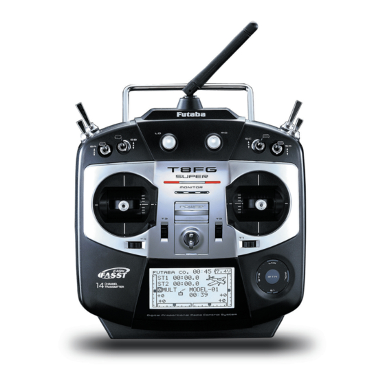
Transmitter controls ●Antenna ●Monitor LED ●Carring Handle ●Volume (LD,RD) ●Switch (SA,SB,SE,SF) ●Switch (SC,SD,SG,SH) ●Slide Lever (LS) ●Slide Lever (RS) ●Stick ●Stick (J2) (J3) (J1) (J4) ●Digital Trim (T1,T2) ●Digital Trim (T3,T4) ●SensorTouch (SYS, LNK, MDL, EXIT, RTN) ●LCD Display ●Power Switch ●Neck Strap Attachment <Before Use>…
-
Page 14: Cautions On Handling Antenna
Monitor LED display Transmitter’s Antenna: The status of the transmitter is displayed by LED As with all radio frequency transmissions, the at the bottom left and right sides of the «T8FG strongest area of signal transmission is from the SUPER» logo. sides of the transmitter’s antenna.
-
Page 15: Volume (Ld, Rd)
Volume Digital Trim Digital Trim T1, T2, T3 and T4: Volume LD and RD: This transmitter is equipped with four (4) digital The volume LD and RD knobs allow analog trims. Each time you press a trim button, the trim input.
-
Page 16: Touch Sensor
Touch sensor operation Data input operation is performed using the touch sensor. SensorTouch™ operation Condition Working • Short ‘tap’ If the screen has more than one page. (Ex. P-MIX screen) The cursor moves to the top of next page. If the screen have only one (1) page. The cursor moves to the top of page.
-
Page 17: Stick Adjustment
Note: Stick Adjustment *Scroll operation: Circle your finger on the outside edge of Adjustment of the stick lever length the RTN button. The sensors may mis-read your touch as a You can adjust the length of stick levers, as you reverse rotation if the circle is smaller, or performed on the inside edge of the RTN button.
-
Page 18: Sd Card
PC by Windows Explorer, etc. The files must be converted and written by the Futaba File System 2. T u r n o n t h e T 8 F G S p o w e r . W h e n a n software.
-
Page 19: Connector/Plug
*If you take out the Ni-MH battery HT6F1700B from Saving model data and update files (released the transmitter, you can use the optional quick charger from Futaba) into the SD card, you can then CR-2000 corresponding to Ni-MH battery. transfer those files to your T8FGS transmitter.
-
Page 20: Installation And Removal Of The Battery
* If there is any problem, the message «Backup Error» will be shown the next time when you turn on the power of the transmitter. Do not use the transmitter as it is. Send it to the Futaba Service Center. <Before Use>…
-
Page 21: Receiver Nomenclature
Receiver nomenclature Before using the receiver, be sure to read the precautions listed in the following pages. The R6208SB has an S.BUS system output port and a conventional system channel output. It can also be used with conventional system servos, etc. in addition to S.BUS system compatible servos and gyros, etc. In addition, the operating mode (high-speed mode/normal mode) can be selected.
-
Page 22: Basic Operation
BASIC OPERATION Battery Charging Before charging batteries, read the «Cautions for handling battery and battery charger» in the section «Ni- MH/Ni-Cd Battery Safety and Handling Instructions». How to charge the Ni-MH battery HT6F1700B *Battery charging will not automatically stop. Remove the battery and transmitter from the charger and remove the for the transmitter charger from the wall socket.
-
Page 23: How To Turn On/Off The Transmitter
How to turn transmitter power ON/OFF Registration of the user’s name When turning on the power, the T8FGS If so desired, the T8FGS transmitter can transmitter will begin emmiting RF automatically indicate the owner’s name. after it confirms the surrounding RF conditions. User’s name setup screen The T8FGS transmitter also offers the ability to 1.
-
Page 24: Home Screen
Home screen Use the touch sensor to select the following display area to call each setting screen, and touch the RTN button. The setting screen appears. System timer Key lock • This shows the accumulated time since • Touch the S1 button for one second the latest reset.
-
Page 25: User Menu
User Menu Warning A user menu which allows the user to customize Be sure to confirm the model name before and display frequently used functions has been flying your aircraft. added. Check the battery voltage as often as possible 1.
-
Page 26: Operation Mode Select (R6208Sb)
Operation Mode Select (R6208SB) The receiver operation mode is on «Normal mode» from factory shipping. To change the mode, please adhere to the following steps: Changing the operation mode Confirming the operation mode Please check the operation mode by observing Link/Mode Button the LED when turning on the receiver.
-
Page 27: S.bus Servo Channel Setting (R6208Sb)
S.BUS Servo Channel Setting (R6208SB) S.BUS servo channel setting can be performed by using an S.BUS compatible receiver, an SBC-1 channel changer or CIU-2 USB serial interface. To set the channel by using your R6208SB, please adhere to the following steps: Channel setting 1.
-
Page 28: Link Procedure (T8Fgs/R6208Sb)
Easy Link (T8FGS/R6208SB) Each transmitter has an individually assigned, unique ID code. In order to start operation, the receiver must be linked with the ID code of the transmitter with which it is being paired. Once the link is made, the ID code is stored in the receiver and no further linking is necessary unless the receiver is to be used with another transmitter.
-
Page 29: Range Testing Your R/C System
Range Testing Your R/C System It is extremely important to range check your models prior to each flying session. This enables you to ensure that everything is functioning as it should and to obtain maximum enjoyment from your time flying. The T8FGS transmitter incorporates a system that reduces its power output and allows you to perform such a range check.
-
Page 30: Receiver And Servo Installation
RECEIVER AND SERVO INSTALLATION Receiver and servos connection Connect the receiver and servos in accordance with the connection diagram shown below. Always read [Precautions when mounting the receiver and servos] or [Before using]. When mounting the receiver and servos to the fuselage, connect the necessary points in accordance with the model’s instruction manual. Receiver and servos connection diagram Always connect the necessary number of servos.
-
Page 31: Servo Connection By Model Type
Servo connection by model type The T8FGS transmitter channels are automatically assigned for optimal combination according to the type selected with the Model Type function of the Linkage Menu. The channel assignment (initial setting) for each model type is shown below. Connect the receiver and servos to match the type used. *The set channels can be checked at the Function screen of the Linkage Menu.
-
Page 32
Ailvator (Dual Elevator) 1AIL (*1) 2AIL (*1) 2AIL+1FLAP (*2) 2AIL+2FLAP (*3) 2AIL+4FLAP (*4) 4AIL+2FLAP (*4) Airplane Glider Airplane Glider Airplane Glider Airplane Glider Airplane Glider Airplane Glider Aileron Aileron Aileron Aileron Aileron Aileron Aileron Aileron Aileron Aileron Aileron Aileron Elevator Elevator Elevator Elevator… -
Page 33
Flying wing, Delta wing (Winglet) 2AIL (*1) 2AIL+1FLAP (*1) 2AIL+2FLAP (*2) 2AIL+4FLAP (*3) 4AIL+2FLAP (*3) Airplane Glider Airplane Glider Airplane Glider Airplane Glider Airplane Glider Aileron Aileron Aileron Aileron Aileron Aileron Aileron Aileron Aileron Aileron Rudder2 Rudder2 Rudder2 Rudder2 Rudder2 Rudder2 Aileron2 Aileron2… -
Page 34
Helicopter ● Since the ch8 doesn’t work on the 7-ch mode, please RX CH H-4, H4X Swash All Other assign the elevator2 (H-4, H4X) or the needle (all Aileron Aileron other) to 7 channnel if the governor is not used. Elevator Elevator Throttle… -
Page 35: Safety Precautions When Installing Receiver And Servos
• Note the small numbers (1, 2, 3, 4) molded into • To prevent the servo lead wires from being each arm on the Futaba 4-arm servo arms. The broken by vibration during flight, provide a slight numbers indicate how many degrees each arm amount of slack or extra so that the wire sticks is “off”…
-
Page 36: Receiver’s Antenna Installation
Receiver’s Antenna Installation You will note that the R6208SB differs in appearance from the standard Futaba receiver. This receiver incorporate two separate antennas into their design which enables them to receive the radio frequency transmission at two different locations. *Must be kept as straight as possible.
-
Page 37: Model Basic Setting Procedure
MODEL BASIC SETTING PROCEDURE Airplane/glider basic setting procedure 1. Model addition and selection manual. For a description of the connection method, see the Receiver and Servos Connection. Initially, the T8FGS assigns the first model to Note that even for the same «airplane model-01 in the transmitter.
-
Page 38
speed of the aileron, elevator, and flap servos can be adjusted. You can also set the Auto Mode, which will link Airbrake to a stick, switch, or dial. A separate stick switch or dial can also be set as the ON/OFF switch. -
Page 39: Helicopter Basic Setting Procedure
Helicopter basic setting procedure This section outlines examples of use of the helicopter functions of the T8FGS. Adjust the actual values, etc. to match the fuselage used. 1. Model addition and selection 3. Flight condition addition Initially, the T8FGS assigns the first model to The transmitter offers up to five flight conditions model-01 in the transmitter.
-
Page 40
4. Servo Connection 5. Throttle/Pitch curve setting Connect the throttle rudder, aileron, elevator, This function adjusts the throttle or pitch pitch, and other servos in accordance with the operation curve in relation to the movement of the kit instruction manual. For a description of the throttle stick for each condition. -
Page 41
6. D/R function for each condition. (At initial setting, this function is in the «INH» state. To use it, set it to the «ON» D/R function is used to adjust the throw and state.) operation curve of aileron, elevator and rudder for each condition. -
Page 42
12. Throttle mixing setting *If throttle mixing is necessary for a compensation for slowing of engine speed caused by swash plate operation during aileron or elevator operation, please refer to the THROTTLE MIX function, p.129. 13. Other special mixings ●Pitch to Needle mixing This mixing is used with engines with a design which allows needle control during flight (fuel-air mixture adjustment). -
Page 43: Functions Of System Menu
SYSTEM MENU The System Menu sets up functions of the transmitter: This does not set up any model data. ● Call the system menu shown below by touching the SYS button twice at the home screen, etc. <SensorTouch™> SYSTEM MENU Scrolling ●…
-
Page 44: Trainer
TRAINER Trainer system starting and setting When using T8FGS as the student transmitter, The Trainer function makes it possible for the (*1) the trainer function is not used. instructor to choose which functions and channels are to be used for instruction, making it possible to (*1) You can select the operation mode for each channel.
-
Page 45
● Select [TRAINER] in the System menu and enter the setup screen shown below by touching the RTN button. <SensorTouch™> Scrolling ● Select the function name ● Moving cursor and return to the System ● Selecting mode menu by touching the ●… -
Page 46
1. Move the cursor to the [RATE] item of the channel you want to change and touch the RTN button to switch to the data input mode. 2. Adjust the rate by scrolling the touch sensor. «RATE»: Adjust the desired rate. Setting range: 0~100% Initial value: 100% *When you want to reset the value to the initial state, touch… -
Page 47: Display
DISPLAY LCD and back-light adjustment LCD contrast, back-light brightness and back- light off-timer adjustment are possible: ● Select [DISPLAY] at the system menu and access the setup screen shown below by touching the RTN button. <SensorTouch™> Scrolling ● Select the function name ●…
-
Page 48: User Name
USER NAME User name registration This function allows the modelers to change the T8FGS user name. *A name of up to 10 characters can be entered as the user name. Please note that a space is also counted as one character.
-
Page 49: Sound
SOUND Turns off the buzzer. The warning sound and other sound of the T8FGS transmitter can be turned off. *When “WARNING” was set to OFF, the no operation alarm (30 minutes), mixing warning sound, and low battery alarm sounds are turned OFF. ●…
-
Page 50: H/W Setting
Note: This will not change the throttle ratchet, H/W reverse etc. Those are mechanical changes that This function reverses the operation direction of must be performed by a Futaba service the sticks, switches, trimmer levers, and knobs. center. Note: This setting reverses the actual operation…
-
Page 51
Stick calibration method *J3 and J4 correction is described below. J3 and J4 correction is performed using the same procedure. 1.Select [CALIBRATION] and access the setup screen shown below by touching the RTN button. 2.Move the cursor to the J3-J4 button and touch the RTN button. -
Page 52: Start Sel
START SEL. Immediately, a model selection can be performed START SEL is a function which starts and can turned ON. With a few quick touches, it is possible perform a model selection immediately. to change models whereas before it would require a multi-step process.
-
Page 53
2. With the input next to the desired sensor button two times. Use the SensorTouch™ to highlighted, press the Return (RTN) button one highlight the Start Selection (START SEL.) and time. then press the Return (RTN) button to confirm the selection. -
Page 54
1. Turn ON the transmitter, activating the Model Select screen. If Model (MDL) has been selected, please be sure to press the Model (MDL) sensor when powering up the transmitter. *Please note: Even if the Model Select function is active, the Power Mode screen will appear when the transmitter is turned ON while simultaneously pressing the Return (RTN) button. -
Page 55: Auto Lock
AUTO LOCK The automatic lock function of two kinds of SensorTouch The Auto Lock function makes it possible to START LOCK automatically lock the transmitter to prevent any Auto Lock functions automatically when the unwanted programming/input when in use. model changes or power is turned on. The auto lock function can be set in two ways.
-
Page 56: Information
INFO Displays the program version, SD card information, and product ID. The T8FGS system program version information, The language displayed in home, menu, and SD card information (current and maximum setup screen is selectable. number of model data and other files), and product ID are displayed on the Information screen.
-
Page 57: Functions Of Linkage Menu
FUNCTIONS OF LINKAGE MENU The Linkage Menu is made up of functions The functions which can be selected depend on which perform model addition, model type the model type. A typical menu screen is shown selection, frequency setting, end point setting, and below.
-
Page 58: Servo Monitor
SERVO MONITOR Servo Test & Graph Display / Displays servo positions. This is used for testing servo movement. In order to prevent any potential difficulties, “Moving Test” (repetition mode) and “Neutral the servo test function will be inoperable, or Test” (fixed position mode) are available. inaccessible, under certain conditions.
-
Page 59: Model Select
MODEL SELECT The Model Selection function performs model addition, selection, deletion, copy, and model name setting. This function is used to load the settings of the always appears in the display screen. desired model into the T8FGS’s memory. The Copy function is used to copy parameters, The settings may be selected from either the settings, etc.
-
Page 60
Model deletion the cursor is deleted. [Adding a character] *The model stored in the transmitter memory or an SD card When a character is selected from the can be deleted. character list and the RTN button is touched, *The current model can not be deleted. that character is added at the position 1. -
Page 61: Model Type
MODEL TYPE This function selects the model type from among airplane, helicopter, and glider. When changing the helicopter swash type Six swash types are available for helicopters. within the following groups, you can leave Six types of main wings and three types of tail the settings other than the SWASH function.
-
Page 62
Model type selection (Airplane, Glider) ●Wing type (Normal) ●Wing type (Tailless wing) ●Rudder type ●Tail type Model type selection (Helicopter) ●Swash type <Functions of Linkage Menu>… -
Page 63: Frequency
4 virtual CH mode is activated. 7CH: FASST-2.4GHz system 7ch mode Area mode selection (Frequency range) *Select the MLT2 or MULT setting for all Futaba FASST- 2.4G Multi-ch mode receivers, regardless of number of The T8FGS transmitter has been designed channels (e.g., R6208SB/R6108SB/6008HS/R6014HS/…
-
Page 64: Function
FUNCTION Channel assignment of each function can be changed. Servo Output Channels When you select model and wing (swash) types, you will find that the optimized combinations of For FASST MLT2 mode, you can set 12 linear servo output channels and functions have been channels and two digital channels.
-
Page 65
[ A T L ] : A T L o p e r a t i o n m o d e . M a x i m u m change near idle or low-stick position, normally used with throttle trim. It is also possible to reverse the travel. -
Page 66: Sub-Trim
SUB-TRIM Setting of neutral position of each servo. The Sub-Trim function is used to set the servo neutral position, and may be used to make fine adjustments to the control surface after linkages and pushrods are hooked up. When you begin to set up a model, be sure that the digital trims are set to their center position.
-
Page 67: Servo Reverse
REVERSE Use to reverse the throw direction. Servo Reverse changes the direction of an to tell whether the servo needs to be reversed or a individual servo’s response to a control input. setting in the function needs to be reversed. See the instructions for each specialized function for further For CCPM helicopters, be sure to read the details.
-
Page 68: Fail Safe
FAIL SAFE Sets the servos operating position when transmitter signals can no longer be received or when the receiver battery voltage drops. The Failsafe function may be used to set up to fly, land as soon as possible. Remember, if the positions that the servos move to in the case of predefined control suddenly moves to a position radio interference.
-
Page 69: End Point
END POINT Sets the travel and limit point of each servo. The End Point function adjusts the left and right servo throws, generates differential throws, and will correct improper linkage settings. The travel rate can be varied from 30% to 140% in each direction on channels 1 to 8(12: FASST MLT2 mode).
-
Page 70: Throttle Cut (Air/Heli Only)
THR CUT Stops the engine safely and easily.(airplane and helicopter only) Throttle cut provides an easy way to stop the *Since conditions are not offered when an Airplane is selected, the Throttle Cut options will vary from the options noted engine.
-
Page 71: Idle Down (Air Only)
IDLE DOWN Lowers the engine idling speed.(airplane only) The Idle Down function lowers the engine to its idle position. Like Throttle Cut, this is usually accomplished by flipping a switch with the throttle stick at idle. The action is not functional at high throttle to avoid accidental dead sticks.
-
Page 72: Swash Ring (Heli Only)
SWASH RING Limits the swash plate travel to within a fixed range. (Helicopter only) This function limits the swash travel to a fixed range in order to prevent damaging the swash linkage by simultaneous operation of the ailerons and elevators. It is very useful in 3D aerobatics which use a large travel.
-
Page 73: Swash (Heli Only, Except H-1)
SWASH Swash AFR and linkage correction function. (helicopter only, except swash type H-1) Neutral Point The following compensation mixing is possible; PIT to AIL, PIT to ELE, AIL to PIT, ELE to AIL, At your linkages, if the servo horn deviates from and ELE to PIT (HR3 mode.) It adjusts the swash- a perpendicular position at neutral, the linkage plate to for proper operation of each control using…
-
Page 74
Mixing rate setting procedure The HR3 swash-plate type will be used as an example to describe mixing rate setting. The mixing used in other swash modes may be different, however, the setting procedure is the same. *When making the following setting, Move the cursor to the item you want to set and touch the RTN button to switch to the data input mode. -
Page 75
Subtrim setting procedure Subtrim can be set at the last page of the swash setting screen. SWASH SUB-TRIM PITCH ADJ. HIGH NEUTRAL MOVING *The sub-trim value set here is reflected at sub-trim of the linkage menu. Pitch adjustment procedure The pitch adjustment function can be used at the last page of the swash setting screen. -
Page 76: T1-T4 Setting
T1-T4 SET. Digital trim settings This function adjusts the digital trim’s step Only the trim displayed on the home screen can amount and operation mode (T1~T4.) be moved to the center position without changing the actual trim’s memory position. When the flight conditions are set, the trim operation can be coupled with the conditions when combination mode is selected.
-
Page 77: Warning
WARNING Mixing warning normal reset Mixing warning at power ON can be normally Warning display: reset to OFF. Airplane: Throttle cut/Idle down/Throttle position/Snap-roll/Motor position/Airbrake/ Motor Helicopter: Condition/Throttle cut/Throttle position/Throttle Hold Glider: Condition/Motor position/Trim-mix/Motor ● Select [WARNING] in the Linkage menu and access the setup screen shown below by touching the RTN button.
-
Page 78: Data Reset
DATA RESET Model memory setting data reset. This function is designed to allow you to reset All model setting: trim settings or all of the settings saved in the active Resets all Linkage and Model Menu functions model memory. You may individually choose to except for Frequency, Model Select, and Model reset the following data;…
-
Page 79: Functions Of Model Menu
MODEL MENU (COMMON FUNCTIONS) Note: The T8FG is designed so that the airplane This section describes the D/R, program mixing, and glider (including EP glider) model types and other functions common to all model types. are compatible with aircraft of similar type Before setting the model data, use the Model wings.
-
Page 80: Servo Monitor (Linkage Menu) Condition Select (Glid/Heli Only)
CONDITION Flight condition’s switch assignment, copy, priority change and condition delay can be set. [except airplane type] This function, in the Model menu, can be used ● A Condition Delay function can be set. Unnecessary fuselage motion which may be to switch the settings of up to 5 flight conditions.
-
Page 81
Condition delay setting (Setup screen page 2) 1. Select the condition for which you want to set. 2. Move the cursor to the «DELAY» item of the channel you want to set and touch the RTN button to switch to the data input mode. Adjust the delay amount by scrolling the touch sensor. -
Page 82: Dual Rate
The angle and curve of each stick function can be set. [All model types] DUAL RATE Dual rate function is used to adjust the amount Neutral position of the dual rate curve can be of throw and the operational curve of the stick set.
-
Page 83
Dual rate setting procedure 5. Neutral position adjustment *Perform the settings below after changing to the circuit # or 1. Function selection condition you want to adjust. Move the cursor to the function selection Move the cursor to the [NT] item and touch item and touch the RTN button to switch to the RTN button to switch to the data input the data input mode. -
Page 84: Program Mix
PROG. MIX Program mixing which can be freely customized. Up to five mixings can be used for each model. [All model types] Mixing ON/OFF switch, control or you may choose to Programmable mixing may be used to correct have mixing remaining on all the time. undesired tendencies of the aircraft, and it may also be used for unusual control configurations.
-
Page 85
●ON/OFF switch setting ●Trim mode ON/OFF setting Move the cursor to the switch item and 1. When changing the trim mode, move the access the switch setup screen by touching cursor to the [TRIM] item and touch the RTN the RTN button and select the switch and ON button to switch to the data input mode. -
Page 86: Fuel Mix (Air/Heli Only)
FUEL MIX Dedicated mixing used to adjust the fuel mixture of applicable engines. [Airplane/helicopter] Note: Initial settings does not assign fuel mix to This function is utilized to refine inflight needle any channel. Prior to utilizing the Fuel Mix adjustments of engines that offer mixture control settings, select an unused channel on your carburetors.
-
Page 87
Setting method Touch the RTN button to end adjustment and return to the cursor mode. *Before using this function, assign the [FUEL MIX] function *Needle high trim works as high trim based on the center. to an unused channel in the Linkage menu [FUNCTION] (Works like ATL trim.) function. -
Page 88: Airplane/Glider Functions
MODEL MENU (AIRPLANE/GLIDER FUNCTIONS) The dedicated mixes, etc. that are applicable position, use the Condition Select function to add when an airplane or glider model type is selected flight conditions. (Up to five conditions can be are displayed in this Model menu functions used) section.
-
Page 89
[Glider, 4 flaps] AIRBRAKE This function is used when airbrakes are AIL to RUD necessary when landing or when diving, etc. during This mix is used when you want to coordinate flight. (Airplane, 2 ailerons or more) the rudder with aileron operation for banking at shallow angles. -
Page 90: Pitch Curve (Air Only)
PIT CURVE [Corresponding model type]: Airplane, general N O T E : W h e n V P P i s n o t a s s i g n e d t o a n y This function adjusts the pitch curve for VPP channel, the pitch curve is not displayed in (Variable Pitch Propeller) airplane.
-
Page 91: Throttle Curve (Air Only)
THR CURVE [Corresponding model type]: Airplane/glider, general NOTE: If this throttle curve function is activated, This function adjusts the throttle curve for you can not use the THR-EXP function within optimum engine speed from throttle stick input. the DUAL RATE function simultaneously. *When throttle curve is set to ON when there is no throttle function;…
-
Page 92: Throttle Delay (Air Only)
THR DELAY [Corresponding model type]: Airplane, general THR-DELAY function is used to slow the response of the throttle stick to simulate the slow response of a turbine engine, etc. ● Select [THR DELAY] at the Model menu and access the setup screen shown below by touching the RTN button.
-
Page 93: Ail Differential (Except 1-Ail)
AIL DIFF. [Corresponding model type]: Airplane/glider, 2 ailerons or more The left and right aileron differential can be adjusted independently. For glider, the differential rate in butterfly mixing can be adjusted. AIL1 AIL 2 (Main Aileron) (Main Aileron) ● Select [AIL DIFF.] at the Model menu AIL 3 AIL 4 and access the setup screen shown…
-
Page 94: Flap Setting (2-Flp And Up)
FLAP SET. [Corresponding model type]: Airplane/glider, 2 flaps or more The up/down travel of each flap (camber flaps: FLP1/2, brake flaps: FLP3/4) can be adjusted independently for each servo according to the wing type. ● The operation reference point of each flap can be offset The camber flaps of a 4-flap model can FLP 4…
-
Page 95
AIL to CMBFLP [Corresponding model type]: Airplane/glider, 2 ailerons + 2 flaps or more This mix operates the camber flaps (FLP1/2) in the aileron mode. When the aileron stick is manipulated, the ailerons and camber flaps perform aileron operation simultaneously to significantly improve the roll axis. -
Page 96: Ail To Camber Flp (2-Ail+2-Flp And Up)95 Ail To Brake Flp (Glid Only, 4-Flp)
AIL to BRAKEFLP [Corresponding model type]: Glider, 4 flaps This mix operates the brake flaps (FLP3/4) in the aileron mode. When the aileron stick is manipulated, the aileron and brake flaps perform the aileron operation simultaneously and the roll axis is improved. ●…
-
Page 97: Ail To Rud
AIL to RUD [Corresponding model type]: Airplane/glider, general Use this mix when you want to mix the rudders with aileron operation. This allows the aircraft to bank at a steep angle. ● Mixing during flight can be turned ON/OFF by a AIL1 AIL 2 switch.
-
Page 98: Rud To Ail
RUD to AIL [Corresponding model type]: Airplane/glider, general This function is used when you want to mix the ailerons with rudder input. It is used when rudder is applied during roll maneuvers such as, knife edge flight. It can be used to turn or bank scale models, large models, etc.
-
Page 99
●5-point curve setting (airplane) [Curve rate setting] 1. Move the cursor to the curve rate setting item (left side) you want to adjust and touch the RTN button to switch to the data input mode. Adjust the rate by scrolling the touch sensor. Adjustment range: -100%~+100% *When the RTN button is touched for one second, the rate is reset to the initial value.) -
Page 100: Camber Mix (Except 1-Ail)
CAMBER MIX [Corresponding model type]: Airplane/glider, 2 ailerons or more This function adjusts the rate of camber ● The up/down side rates of the aileron, flap, and elevator servos can be adjusted. When the mixing operation for the wing camber (ailerons, camber direction is reversed by the linkage, adjustments flaps, brake flaps) in the negative and positive can be made by changing the mixing rate…
-
Page 101
Setting method When setting a cut switch, move the cursor to the [CUT-SW] item and touch the RTN ●Activate the function button to access the selection screen. Select the switch and set its ON direction. (Always Move the cursor to the [ACT] item and touch ON at «—«… -
Page 102: Ele To Camber (Except 1-Ail)
ELE to CAMBER [Corresponding model type]: Airplane/glider, 2 ailerons or more This function is used when you want to mix the ● In-flight mixing can be turned ON/OFF by assigning this to a switch. (Always ON at [—] setting) camber flaps with elevator operation. When used, ●…
-
Page 103
CMBFLP to ELE [Corresponding model type]: Airplane/glider, 2 ailerons + 1 flap or more When the camber/speed flaps are utilized, the aircraft might experience, a change in pitch. This mix compensates for such changes by incorporating elevator input. ● The elevator servos up/down rates can be FLP 1 FLP 2 adjusted separately. -
Page 104: Butterfly (Glid Only, Normal Wing 2-Ail And Up, Flying Wing 2-Ail+1Flp And Up)
BUTTERFLY [Corresponding model type]: Glider, Normal: 2 ailerons or more Flying: 2 ailerons + 1 flap or more This function is utilized to quickly slow the 3. Create more lift toward the center of the wing allowing it to fly at a slower speed aircraft and reduce altitude by simultaneously ●…
-
Page 105
Setting method ● Elevator compensation curve adjustment Output (Y) Position (X) ●Activate the function Offset point Fixed (0) Fixed (offset Move the cursor to the [ACT] item and touch position) the RTN button to switch to the data input 2- Intermediate point Settable Settable mode. -
Page 106: Trim Mix (Glid Only, 2-Ail And Up)
TRIM MIX [Corresponding model type]: Glider, 2 ailerons or more This function adjusts the trim offset rates of the smooth transition between the two conditions. It ailerons, elevators, and flaps (camber flaps, brake is also possible to program a cut switch which flaps) according to the flight status.
-
Page 107
Setting method Initial value: 0 Adjustment range: 0~27 ●Activate the function *When the RTN button is touched for one second, the servo Move the cursor to the [ACT] item and touch operation position is reset to the initial value.) the RTN button to switch to the data input Touch the RTN button to end the adjustment mode. -
Page 108: Airbrake (Air Only, 2-Ail And Up)
AIRBRAKE [Corresponding model type]: Airplane, 2 ailerons or more This function is used to increase the aircraft’s Setting example for F3A and other flaperon specifications drag and is useful for landing or diving, etc. (When 2 ailerons model type selected) The preset elevators and flaps (camber flap, Offset rate: brake flap) offset amount can be activated by a…
-
Page 109
Setting method ●Servo speed setting Move the cursor to the aileron, flap or ●Activate the function elevator speed item and touch the RTN Move the cursor to the [ACT] item and touch button to switch to the data input mode. the RTN button to switch to the data input Adjust the rate by scrolling the touch sensor. -
Page 110: Gyro (Air Only, For Gya Type Gyro)
GYRO [Corresponding model type]: Airplane/glider, general Note: This setting does not assign a sensitivity This function is used when a GYA Series gyro channel. To do so, use the Linkage menu is used to stabilize the aircraft’s attitude. The prior to assigning the sensitivity channel sensitivity and operation mode (Normal mode/ (Gyro/Gyro2/Gyro3), be sure to select an AVCS mode) can be changed via a switch.
-
Page 111
Adjustment range: 0~100% *When a Futaba GYA gyro is used and [GY] type is selected, *When the RTN button is touched for one second, the the sensitivity set value is directly read in both the AVCS sensitivity is reset to the initial value.) -
Page 112: V-Tail
V-TAIL [Corresponding model type]: Airplane/glider, V-tail V-TAIL This function enables adjustments for left and right rudder angle changes during elevator and rudder operation of a V-tail airplane. V-tail is when two servos are used together to control rudder movement as elevators. In addition ELEVATOR to each elevator side moving up and down together, (RUDDER 2)
-
Page 113: Ailevator
AILEVATOR [Corresponding model type]: Airplane/glider, Ailevator (Effective only when 2 servos used at the elevators) This function improves the performance of the roll axis by operating the elevators as ailerons. Ailevator is where each elevator in a standard (conventional) or v-tail moves independently, like ailerons on a wing.
-
Page 114: Winglet (Flying Wing Only)
WINGLET [Corresponding model type]: Airplane/glider, Flying wing only This function adjusts the left and right rudder angles of airplanes with winglets. Winglets are used to improve the efficiency of aircraft by lowering the lift-induced drag caused by wingtip vortices. The winglet is a vertical or angled extension located at the tip of each wing.
-
Page 115: Motor
MOTOR [Corresponding model type]: Airplane/glider, general This function lets you set the speed when the time operation, set the ACT/INH item to [INH] and then reset it to [ON]. motor of an F5B or other EP glider is started via ●…
-
Page 116
● ON/OFF direction ● Motor function switch current position Setting method ●Start switch function ● Activate the motor speed function When active, the «START SW» allows the motor’s state to change from OFF to ON. The When using motor speed function, move the motor is ON when the main SW and «START cursor to the [INH] item and touch the RTN SW»… -
Page 117: Rud To Ele (Air Only)
RUD to ELE [Corresponding model type]: Airplane, general This function is used when you want to mix ● Mixing during flight can be turned ON/OFF by setting a switch. (Always ON at [—] setting) elevator operation with rudder operation. It is used ●…
-
Page 118: Snap Roll (Air Only)
SNAP ROLL [Corresponding model type]: Airplane, general This function selects the switch and rate (Example) Setting example for F3A adjustment of ailerons, elevators, and rudder when ● Mode: [Master] a snap roll is performed. ● Safety SW: [SG] (Safety measure) ●…
-
Page 119
Setting method ●Master/single mode selection Move the cursor to the [MODE] item and touch the RTN button to switch to the data input mode. Select the master or single mode by scrolling the touch sensor. *The display blinks. [MASTER]: Master mode [SINGLE]: Single mode Touch the RTN button to select the mode and return to the cursor mode. -
Page 120: Helicopter Functions
MODEL MENU (HELICOPTER) This section contains information on the Condition Select screen prior to adjusting the commands that apply to helicopters only. For model’s parameters. (Up to five conditions can be instructions on Airplanes and Sailplanes, refer to used) the sections pertaining to those aircraft. The Dual Rate function and other functions Use the Model Type function in the Linkage common to all model types have already been…
-
Page 121: Pit Curve/Pit Trim
PIT CURVE/PIT TRIM Pitch Curve This function adjusts the pitch operation curve *A simple curve can be created by reducing the number of input points to two or three, and then entering the specified for each flight condition to optmize the model’s value at the corresponding points.
-
Page 122
Curve setting examples When actually creating a curve, input the rate The screens shown below are curves created by specified by the model (or the reference value). entering the pitch rate at low, center, and high side (3 points or 5 points) at each condition. ●Pitch Curve (Example) Normal Curve Idle-up 1 Curve… -
Page 123
[Low/High pitch trim setting] High Pitch/Low Pitch Trim Setting method High Pitch/Low Pitch Trim is the pitch servo ● Set the function to ACT (ON). high side and low side trim function. ● Select the adjustment knobs. Selection example: LS (high side), RS (low side) ●… -
Page 124: Thr Curve/Throttle Hover Trim/Throttle
THR CURVE/THROTTLE HOVER TRIM Throttle Curve Throttle curve function adjusts the throttle accompanying changes in the temperature, operation curve for each condition to optimize the humidity, and other flight conditions can be engine speed to throttle stick movement. trimmed. Adjust the throttle so that rotor rotation is most stable.
-
Page 125
Curve setting examples condition. When actually creating a curve, enter the The curves shown below are created by inputting parameters specified per the model (or the reference the data of the 5 points 0% (low side), 25%, value). 50% (center), 75%, 100% (high) side for each ●Throttle Curve (Example) Normal Curve Idle-up 1 Curve… -
Page 126
Throttle limiter function [Throttle limiter setting] This function limits the high range of the throttle movement by any slider or trimmer. *Control which adjusts the limit point during flight can be set. Setting method •Limiter operating range adjustment control setting *Set at the 3rd page of the throttle curve screen. -
Page 127: Throttle Hold
THR HOLD This function sets the throttle cut position for Note: Initially, this setting does not assign the throttle hold switch. Prior to adjusting the auto rotation. The throttle servo operating speed parameters for the throttle hold, we suggest can be adjusted. (Speed) designating a throttle hold switch.
-
Page 128: Swash Mix
SWASH MIX Example of use The swash mix function is used to correct the ● As an example, use swash mixing to correct swash plate in the aileron (roll) direction and undesirable roll tendencies. elevator (cyclic pitch) corresponding to each ●…
-
Page 129: Throttle Mix
THROTTLE MIX Setting example This function corrects slowing of engine speed ● AIL to THR mixing counteracts the lag in caused by swash plate operation during aileron engine RPM’s when an aileron input is given or elevator operation. The method of applying to the helicopter.
-
Page 130: Pit To Rud (Revolution Mix)
PIT to RUD mixing (Revolution mixing) Note: When a GY Series or other heading hold Use this mix when you want to suppress the gyro is used, since correction is performed by reaction torque generated by main rotor pitch and the gyro, this mix is not utilized.
-
Page 131: Gyro (For Gy Type Gyro)
GYRO mixing This function used to adjust gyro sensitivity. Note: When using the [Gyro2]/[Gyro3] function, assign [Gyro2]/[Gyro3] to any channel on the The sensitivity and operation mode (Normal mode/ function screen. AVCS mode) can be set for each condition. Always set to [—] both (Control) and (Trim) for The gyro sensitivity can be switched with each the [Gyro] function at the Function menu in condition or the switch.
-
Page 132
Initial value: 0% *When a Futaba GYA gyro is used and [GY] type is selected, Adjustment range: -20~+20% the sensitivity set value is directly read in both the AVCS *When the RTN button is touched for one second, the and NORM modes. -
Page 133: Governor
GOVERNOR mixing When using a Futaba GV-1/GY701/CGY750 *When using an independent governor [ON]/[OFF] switch, connect the AUX([ON]/[OFF]) connector of the governor to governor, this function is used to switch the RPM CH8 and set the switch to CH8 (Governor2) at the Function of the helicopter’s rotor head.
-
Page 134
the RTN button to switch to the data input mode. Select the unit by scrolling the touch sensor. T o u c h t h e R T N b u t t o n t o c h a n g e t h e operation mode and return to the cursor mode. -
Page 135: Appendix
TIMER ST1/ST2 Timer setting The Timer function may be set for any desired a long tone at the target time, and continue counting time, i.e. engine run time, specified times for with displaying a minus (-) sign. Count-up timers competitions, etc. Two independent timers are also beep the last twenty and ten seconds, beep the provided for your use.
-
Page 136: Timer St1/St2
Timer setting Timer operation ● Timer ST1 and ST2 are started/stopped by ●Up timer/down timer setting pre-selected start/stop switch. Move the cursor to the [MODE] item and ● To reset a timer, operate the pre-selected touch the RTN button to switch to the data reset switch, or move the cursor to the [RESET] input mode.
-
Page 137: Switch Setting Method
Switch Setting Method The various functions used in the T8FG can is, whenever the manual indicates that something is be activated by a switch. For the purposes of this operated via a switch, it is possible for the user to manual, a stick position, VR position, etc.
-
Page 138
Operation modes Shifting the ON/Off point The operation modes available when stick, trim The ON/OFF point can be shifted. ON/OFF at lever, or knob was selected are described below. a free position can be changed. Linear mode [LIN] ●Black range: OFF range ●White range: ON range [Setting method] This mode sets ON/OFF to the left or right (up… -
Page 139
To return to the preceeding screen, move the cursor to the [SWITCH] at the top of the screen and touch the RTN button. FUTABA CORPORATION Phone: +81 475 32 6982, Facsimile: +81 475 32 6983 1080 Yabutsuka, Chosei-mura, Chosei-gun, Chiba-ken, 299-4395, Japan ©FUTABA CORPORATION 2013, 03 (2) <Appendix>…

Тема: Инструкция на Futaba 8fg на русском языке (ссылка) (Прочитано 16060 раз)

0 Пользователей и 1 Гость просматривают эту тему.
А на 14 sg нет случайно? Интересует режим гироспопа.
Jexa
http://www.fpv-community.ru/uploads/Futaba14SG_rus.pdf, правда там подробно разжёвано про самолётный режим, но принцип общий  , правда полистал выше представленную, думаю там есть все ответы на твои вопросы, связанные с гирой.
« Последнее редактирование: 09 Ноябрь, 2014, 22:22:50 pm от JeXa »
Как включить режим удержания?
Это смотря что за гира.
По умолчанию — «avcs»
Крылья, шасси, главное Хвост!
Как включить режим удержания?
Это смотря что за гира.
По умолчанию — «avcs»
Гиро микробиста.
« Последнее редактирование: 09 Ноябрь, 2014, 23:56:09 pm от Galantniy »
Гиро микробиста.
avcs и % чюйки
Крылья, шасси, главное Хвост!
Гиро микробиста.
avcs и % чюйки
Тоесть в актив 1 поставить avcs, а в актив 2 проценты?
Тоесть в актив 1 поставить avcs, а в актив 2 проценты?
У тебя там не самолёт ли, случаем, выбран?
В вертолёте режимы называются не «актив».
В вертолёте д.б. так:
Тоесть в актив 1 поставить avcs, а в актив 2 проценты?
У тебя там не самолёт ли, случаем, выбран?
В вертолёте режимы называются не «актив».В вертолёте д.б. так:
Выбран не самолет, но выглядит по другому. Тоесть заходя в gyro, попадаю сразу в Rud.
У Вас выглядит по другому скорее всего по тому что выбрано 7 каналов, если выбрать 12 и более, то в меню будет больше гироскопов.
Сам так чуть не попался при настройке  , подумал что совсем все забыл
  .
.
Тоесть в актив 1 поставить avcs, а в актив 2 проценты?
У тебя там не самолёт ли, случаем, выбран?
В вертолёте режимы называются не «актив».В вертолёте д.б. так:
Выбран не самолет, но выглядит по другому. Тоесть заходя в gyro, попадаю сразу в Rud.
У вас все нормально(правильно).
В настройках гироскопа сделайте его переключение на один из тумблеров, а чуйку лучше всего вывести на крутилку LD/
http://www.fpv-community.ru/uploads/Futaba14SG_rus.pdf, правда там подробно разжёвано про самолётный режим, но принцип общий
Мне очень помогло разобраться с миксами.
ЭХХХХ — было бы их хотя бы 10 штук, не пришлось бы сейчас шаманить контроллер для независимого управления двумя головами  .
.
Для двухроторного верта.
А на 14 sg нет случайно? Интересует режим гироспопа.
Будет и для Futaba T14SG, но не очень скоро. Осталось перевести 50 страниц. Но врядли это поможет для понимания режимов гироскопа, руководство мутное какое-то. Режимы «Normal» и «GY» мало чем отличаются, в «Normal» диапазон настройки чувствительности 0-100%, а в «GY» диапазон настройки чувствительности -100%~+100%, вот и вся разница.
ВОЗВРАЩЕНИЕ FPV ЛЕГЕНДЫ!
Аппаратуры фирмы Futaba на сегодняшний день обладают самым стабильным и самым дальним радиолинком среди всех промышленных модельных аппаратур. Именно поэтому они так любимы RC спортсменами и FPV пилотами. Без всяких бустеров и LRS систем дальность управления моделью может достигать 3-5 километров! Благодаря особому защищенному протоколу FASST на дальность практически не влияет даже очень мощный сигнал от видеопередатчика, включая частоту 1.2Ghz, которая из-за эффекта интерференции у многих других аппаратур 2.4Ghz вызывает определенные проблемы. Это очень важно. 14 каналов управления позволит реализовать на FPV модели все мыслимые и немыслимые функции, включая управление камерой и бортовыми огнями.
Футабу отличает качество сборки, удобство и богатый набор настроек, эргономика, интересный дизайн, информативности дисплея, понятный интерфейс. В меню так же присутствует русский язык!

8FG задумана и сконструирована так, что балансировка проходит по ушку крепления ремешка. Идеальная развесовка.

Так же аппаратура комплектуется новейшим приемником R6208SB, он поддерживает последние технологии S.BUS и сервы High Voltage!
Особенности Futaba 8FG:
- 12 пропорциональных каналов
- 2 дискретных канала
- Использование технологии FASST 2.4ГГц — лучшая дальность и защищенность канала управления от влияние 1.2Ghz передатчиков
- Разрешение управления в 2048 точек
- Удобное программирование через SensorTouch™ (сенсорная панель)
- Программы для самолетов, вертолетов и планеров
- Внутренняя память на 20 моделей, неограниченная на внешней SD карте
- Любые Mode 1-4 по выбору пилота, по-умолчанию Mode-2
- Настраиваемое меню пользователя
- Прямой доступ к множеству таймеров, настройкам каналов и выбору моделей
- Доступ в 2 прикосновения к системным настройкам, связям и меню моделей
- Имена пользователей и моделей — до 10 символов
- Выбор моделей, копирование и сброс настроек
- Защита от пропадания сигнала по всем каналам
- Субтриммеры, реверс сервомашинок, двойные расходы, экспоненты, конечные точки с раздельной установкой пределов регулировки
- Цифровые триммеры и память, ступенчато или в % от показаний
- 128 x 64 LCD-дисплей с фоновой подстветкой, с автоматическим отключением по таймеру, нормальным или большим отображением таймера на экране, регулируемые контраст и яркость
- Циклический сигнал для сервоприводов с графической индикацией
- Система «Trainer» с функцией назначения каналов
- Стики с шарикоподшипниками, регулировкой длины и усилия
- Меню калибровки стиков
- Меню аппаратуры на русском языке
Помимо очень хорошей дальности «из коробки», Футаба лучше чем любая другая аппаратура дружит с бустерами. Усиленная бустером Футаба позволяет летать на десятки километров, что ничуть не хуже (а иногда и лучше) дальности многих LRS систем. В любом случае LRS системы так же удобно и без проблем подключаются через «тренерский» разъем.
В комплекте:
- Аппаратура Futaba 8FG (14 каналов управления)
- Приемник R6208SB
- Ремешок
- Аккумулятор 7.2V 1700mAh
- Зарядник
- Инструкция, коробка
Инструкция на русском языке: http://yadi.sk/d/inbQitylApzJD
PS. За долгие годы существования FPV как направления хобби, Futaba 8FG показала себя одной из самых востребованных и надежных FPV аппаратур. Там есть все, что необходимо пилоту. Если вас не пугает цена, то пожалуй это будет лучший выбор из всего, что представлено на рынке. Сейчас эти аппаратуры уже не производятся (их место заняла более дорогая модель 14SG), однако они остаются самыми популярными и востребованными. У вас есть уникальный шанс купить Futaba 8FG Super по очень хорошей цене и никогда не жалеть о сделанном выборе!
-
Contents
-
Table of Contents
-
Bookmarks
Quick Links
8FG SUPER
14-CHANNEL RADIO CONTROL SYSTEM
FASST-2.4GHz Multi-ch/7-ch mode selectable
INSTRUCTION MANUAL
1M23N22209
Related Manuals for FUTABA 8FG SUPER
Summary of Contents for FUTABA 8FG SUPER
-
Page 1
8FG SUPER 14-CHANNEL RADIO CONTROL SYSTEM FASST-2.4GHz Multi-ch/7-ch mode selectable INSTRUCTION MANUAL 1M23N22209… -
Page 2: Table Of Contents
TABLE OF CONTENTS INTRODUCTION……….4 5DQJH WHVWLQJ RXU 5& VVWHP…… 29 6XSSRUW DQG 6HUYLFH ……… 4 RACEIVER AND SERVO INSTALLATION 30 $SSOLFDWLRQ ([SRUW DQG 0RGL¿FDWLRQ … 5 5HFHLYHU DQG VHUYRV FRQQHFWLRQ ….. 30 ‘H¿QLWLRQV RI 6PEROV ……..6 6HUYR FRQQHFWLRQ E PRGHO WSH ….31 6DIHW 3UHFDXWLRQV GR QRW RSHUDWH ZLWKRXW UHDGLQJ ………….
-
Page 3
FUNCTIONS OF MODEL MENU ….75 *UR IRU *< WSH JUR ……127 *RYHUQRU …………129 &RPPRQ )XQFWLRQV ……..75 6HUYR 0RQLWRU /LQNDJH 0HQX &RQGLWLRQ 6HOHFW *OLG+HOL RQO ….76 APPENDIX …………131 Dual Rate …………78 7LPHU 6767 ……….131 3URJUDP 0L[ ……….. -
Page 4: Introduction
Thank you for purchasing a Futaba FASST-2.4GHz 8FG SUPER series digital proportional R/C system. This system is extremely versatile and may be used by beginners and pros alike. In order for you to make the best use RI RXU VVWHP DQG WR À VDIHO SOHDVH UHDG WKLV PDQXDO FDUHIXOO ,I RX KDYH DQ GLI¿FXOWLHV ZKLOH XVLQJ RXU VVWHP SOHDVH FRQVXOW WKH PDQXDO RXU RQOLQH )UHTXHQWO $VNHG 4XHVWLRQV RQ WKH ZHE SDJHV UHIHUHQFHG EHORZ RXU KREE GHDOHU RU WKH )XWDED 6HUYLFH &HQWHU…
-
Page 5: Ssolfdwlrq
7KLV GHYLFH PXVW DFFHSW DQ LQWHUIHUHQFH UHFHLYHG LQFOXGLQJ LQWHUIHUHQFH WKDW PD FDXVH XQGHVLUHG operation. The responsible party of this device compliance is: Futaba Service Center 1 $SROOR ‘ULYH 6XLWH &KDPSDLJQ ,/ 86$ 7(/ RU (PDLO VXSSRUW#IXWDEDUFFRP 6XSSRUW 7(/ RU (PDLO VHUYLFH#IXWDEDUFFRP 6HUYLFH 7KH 5%5& 6($/ RQ WKH QLFNHOFDGPLXP EDWWHU FRQWDLQHG LQ )XWDED SURGXFWV LQGLFDWHV WKDW…
-
Page 6: H¿Qlwlrqv Ri 6Perov
)HGHUDO &RPPXQLFDWLRQV &RPPLVVLRQ ,QWHUIHUHQFH 6WDWHPHQW IRU 86$ 7KLV HTXLSPHQW KDV EHHQ WHVWHG DQG IRXQG WR FRPSO ZLWK WKH OLPLWV IRU D &ODVV % GLJLWDO GHYLFH SXUVXDQW WR 3DUW RI WKH )&& 5XOHV 7KHVH OLPLWV DUH GHVLJQHG WR SURYLGH UHDVRQDEOH SURWHFWLRQ DJDLQVW KDUPIXO LQWHUIHUHQFH LQ a residential installation.
-
Page 7
1L0+1L&G %DWWHU &KDUJH WKH EDWWHULHV 6HH &KDUJLQJ WKH 1L&G EDWWHULHV IRU GHWDLOV $OZDV UHFKDUJH WKH WUDQVPLWWHU DQG UHFHLYHU EDWWHULHV EHIRUH HDFK ÀLQJ VHVVLRQ $ ORZ EDWWHU ZLOO VRRQ GLH SRWHQWLDOO FDXVLQJ ORVV RI FRQWURO DQG D FUDVK :KHQ RX EHJLQ RXU ÀLQJ VHVVLRQ UHVHW RXU 7)*6¶V EXLOWLQ WLPHU DQG GXULQJ WKH VHVVLRQ pay attention to the duration of usage. -
Page 8
1L0+1L&G %DWWHU 6DIHW DQG +DQGOLQJ LQVWUXFWLRQV ,03257$17 Use only the )XWDED VSHFLDO FKDUJHU LQFOXGHG ZLWK WKLV VHW RU RWKHU FKDUJHUV DSSURYHG E )XWDED WR FKDUJH WKH 1L0+ EDWWHULHV LQ WKH 7)*6 WUDQVPLWWHU LQFOXGHG ZLWK WKLV VHW ,W LV LPSRUWDQW WR XQGHUVWDQG WKH RSHUDWLQJ FKDUDFWHULVWLFV RI 1L0+1L&G EDWWHULHV$OZDV UHDG WKH VSHFL¿FDWLRQV SULQWHG RQ WKH ODEHO RI RXU 1L0+1L&G EDWWHU DQG FKDUJHU SULRU WR XVH )DLOXUH WR IROORZ WKH SURFHHGLQJ SUHFDXWLRQV FDQ TXLFNO UHVXOW LQ VHYHUH SHUPDQHQW GDPDJH WR WKH EDWWHULHV DQG LWV VXUURXQGLQJV DQG possibly result in a ),5(… -
Page 9
$W WKH ÀLQJ ¿HOG 7R SUHYHQW SRVVLEOH GDPDJH WR RXU UDGLR JHDU WXUQ WKH SRZHU VZLWFKHV RQ DQG RII LQ WKH SURSHU VHTXHQFH 3XOO WKURWWOH VWLFN WR LGOH SRVLWLRQ RU RWKHUZLVH GLVDUP RXU PRWRUHQJLQH 7XUQ RQ WKH WUDQVPLWWHU SRZHU DQG DOORZ RXU WUDQVPLWWHU WR UHDFK LWV KRPH VFUHHQ &RQ¿UP WKH SURSHU PRGHO PHPRU KDV EHHQ VHOHFWHG 7XUQ RQ RXU UHFHLYHU SRZHU 7HVW DOO FRQWUROV ,I D VHUYR RSHUDWHV DEQRUPDOO GRQ¶W DWWHPSW WR À XQWLO RX GHWHUPLQH WKH FDXVH RI WKH… -
Page 10: Before Use
BEFORE USE )HDWXUHV )$667*+] VVWHP 7KH 7)*6 WUDQVPLWWHU LV FDSDEOH RI WUDQVPLWWLQJ LQ ERWK )$667* FK DQG 0XOWLFK PRGHV 6HOHFW WKH GHVLUHG PRGXODWLRQ PRGH LQ WKH )UHTXHQF 0HQX )RU FRPSOHWH GHWDLOV RQ KRZ WR GR VR SOHDVH UHIHU WR WKH )UHTXHQF 6HOHFWLRQ VHFWLRQ ORFDWHG HOVHZKHUH LQ WKLV PDQXDO 7KH FRPSDWLELOLW LV GHSHQGHQW XSRQ WKH UHFHLYHU VHOHFWHG 7KH 56% UHFHLYHU LV FDSDEOH RI FRQWUROOLQJ PRGHOV XS WR HLJKW FKDQQHOV E XVLQJ WKH RXWSXWV IRU FRQYHQWLRQDO VVWHP DQG XS WR IRXUWHHQ FKDQQHOV LQFOXGLQJ WKH WZR GLJLWDO FKDQQHOV E XVLQJ WKH RXWSXW IRU 6%86 VVWHP 56% KDV WZR RSHUDWLRQ PRGH DV VKRZQ EHORZ…
-
Page 11: Rqwhqwv Dqg Whfkqlfdo Vshfl¿Fdwlrqv
&RQWHQWV DQG 7HFKQLFDO 6SHFL¿FDWLRQV 6SHFL¿FDWLRQV DQG UDWLQJV DUH VXEMHFW WR FKDQJH ZLWKRXW QRWLFH <RXU )* 683(5 LQFOXGHV WKH IROORZLQJ FRPSRQHQWV ‡ 7)*6 WUDQVPLWWHU IRU DLUSODQHV RU KHOLFRSWHUV 6XJJHVWHG 6HUYR IRU XVH ZLWK RXU )* 683(5 VVWHP ‡ 56% 5HFHLYHU 6HUYR 6 ‘LJLWDO VHUYR ‡…
-
Page 12: Ffhvvrulhv
7KH IROORZLQJ DGGLWLRQDO DFFHVVRULHV DUH DYDLODEOH IURP RXU GHDOHU 5HIHU WR D )XWDED FDWDORJ IRU PRUH LQIRUPDWLRQ ‡ +7)% 7UDQVPLWWHU EDWWHU SDFN WKH P$K WUDQVPLWWHU 1L0+ EDWWHU SDFN PD EH HDVLO H[FKDQJHG ZLWK D IUHVK RQH WR SURYLGH HQRXJK FDSDFLW IRU H[WHQGHG ÀLQJ VHVVLRQV ‡…
-
Page 13: 7Udqvplwwhu Frqwurov
7UDQVPLWWHU FRQWUROV $QWHQQD 0RQLWRU /(‘ &DUULQJ +DQGOH 9ROXPH /’5’ 6ZLWFK 6$6%6(6) 6ZLWFK 6&6’6*6+ 6OLGH /HYHU /6 6OLGH /HYHU 56 6WLFN 6WLFN (J2) (J3) (J1) (J4) ‘LJLWDO 7ULP 77 ‘LJLWDO 7ULP 77 6HQVRU7RXFK 6<6 /1. 0’/ (;,7 571 /&’ ‘LVSOD 3RZHU 6ZLWFK 1HFN 6WUDS $WWDFKPHQW %HIRUH 8VH!
-
Page 14: Dxwlrqv Rq Kdqgolqj Dqwhqqd
0RQLWRU /(‘ GLVSOD 7UDQVPLWWHU
V $QWHQQD 7KH VWDWXV RI WKH WUDQVPLWWHU LV GLVSODHG E /(‘ $V ZLWK DOO UDGLR IUHTXHQF WUDQVPLVVLRQV WKH at the bottom left and right sides of the «T8FG strongest area of signal transmission is from the SUPER» logo. VLGHV RI WKH WUDQVPLWWHU
V DQWHQQD $V VXFK WKH antenna should not be pointed directly at the model. -
Page 15: 9Roxph /’ 5
Volume ‘LJLWDO 7ULP ‘LJLWDO 7ULP 7 7 7 DQG 7 Volume LD and RD: 7KLV WUDQVPLWWHU LV HTXLSSHG ZLWK IRXU GLJLWDO 7KH YROXPH /’ DQG 5′ NQREV DOORZ DQDORJ WULPV (DFK WLPH RX SUHVV D WULP EXWWRQ WKH WULP input.
-
Page 16: 7Rxfk Vhqvru
7RXFK VHQVRU RSHUDWLRQ Data input operation is performed using the touch sensor. SensorTouch™ operation Condition Working If the screen has more than one page. (Ex. P-MIX screen) The cursor moves to the top of next page. If the screen have only one (1) page. The cursor moves to the top of page.
-
Page 17: Stick Adjustment
Note: Stick Adjustment 6FUROO RSHUDWLRQ &LUFOH RXU ¿QJHU RQ WKH RXWVLGH HGJH RI $GMXVWPHQW RI WKH VWLFN OHYHU OHQJWK the RTN button. The sensors may mis-read your touch as a <RX FDQ DGMXVW WKH OHQJWK RI VWLFN OHYHUV DV RX UHYHUVH URWDWLRQ LI WKH FLUFOH LV VPDOOHU RU SHUIRUPHG RQ WKH inside edge of the RTN button.
-
Page 18: 6′ Fdug
6′ &DUG 6HFXUH ‘LJLWDO PHPRU FDUG 1RW ,QVHUWLQJUHPRYLQJ WKH 6′ FDUG LQFOXGHG The T8FGS transmitter model data can be stored by using any commonly found SD card. When 7)*6 WUDQVPLWWHU XSGDWH VRIWZDUH LV UHOHDVHG WKH VRIWZDUH LV XSGDWHG XVLQJ DQ 6′ FDUG 7KH 7)*6 LV FDSDEOH RI XVLQJ 6’ FDUGV ZLWK D PHPRU VL]H SD Card Slot EHWZHHQ 0% DQG *%…
-
Page 19: Rqqhfwru3Oxj
DIWHU D ORQJ SHULRG RI XVH ZH VXJJHVW REWDLQLQJ D QHZ 6′ FDUG WR DYRLG IXUWKHU GLI¿FXOWLHV *Futaba is not responsible for compensating any failure or GDPDJH WR WKH GDWD VWRUHG LQ WKH PHPRU FDUG $V VXFK ZH suggest that you maintain a backup of your important data contained on your SD card.
-
Page 20: Qvwdoodwlrq Dqg Uhprydo Ri Wkh Edwwhu
,I WKHUH LV DQ SUREOHP WKH PHVVDJH %DFNXS (UURU ZLOO EH VKRZQ WKH QH[W WLPH ZKHQ RX WXUQ RQ WKH SRZHU RI the transmitter. Do not use the transmitter as it is. Send it to the Futaba Service Center. %HIRUH 8VH!
-
Page 21: 5Hfhlyhu Qrphqfodwxuh
5HFHLYHU QRPHQFODWXUH %HIRUH XVLQJ WKH UHFHLYHU EH VXUH WR UHDG WKH SUHFDXWLRQV OLVWHG LQ WKH IROORZLQJ SDJHV 7KH 56% KDV DQ 6%86 VVWHP RXWSXW SRUW DQG D FRQYHQWLRQDO VVWHP FKDQQHO RXWSXW ,W FDQ DOVR EH XVHG ZLWK FRQYHQWLRQDO VVWHP VHUYRV HWF LQ DGGLWLRQ WR 6%86 VVWHP FRPSDWLEOH VHUYRV DQG JURV HWF ,Q DGGLWLRQ WKH RSHUDWLQJ PRGH KLJKVSHHG PRGHQRUPDO PRGH FDQ EH VHOHFWHG DATA port system (1 to
-
Page 22: Basic Operation
BASIC OPERATION %DWWHU &KDUJLQJ %HIRUH FKDUJLQJ EDWWHULHV UHDG WKH &DXWLRQV IRU KDQGOLQJ EDWWHU DQG EDWWHU FKDUJHU LQ WKH VHFWLRQ 1L 0+1L&G %DWWHU 6DIHW DQG +DQGOLQJ ,QVWUXFWLRQV %DWWHU FKDUJLQJ ZLOO QRW DXWRPDWLFDOO VWRS 5HPRYH WKH +RZ WR FKDUJH WKH 1L0+ EDWWHU +7)% battery and transmitter from the charger and remove the IRU WKH WUDQVPLWWHU FKDUJHU IURP WKH ZDOO VRFNHW…
-
Page 23: Rz Wr Wxuq 212)) Wkh Wudqvplwwhu
+RZ WR WXUQ WUDQVPLWWHU SRZHU 212)) 5HJLVWUDWLRQ RI WKH XVHU
V QDPH :KHQ WXUQLQJ RQ WKH SRZHU WKH 7)*6 ,I VR GHVLUHG WKH 7)*6 WUDQVPLWWHU FDQ WUDQVPLWWHU ZLOO EHJLQ HPPLWLQJ 5) DXWRPDWLFDOO LQGLFDWH WKH RZQHU
V QDPH DIWHU LW FRQ¿UPV WKH VXUURXQGLQJ 5) FRQGLWLRQV 8VHU
V QDPH VHWXS VFUHHQ The T8FGS transmitter also offers the ability to DXWR VKXWGRZQ… -
Page 24: Rph Vfuhhq
+RPH VFUHHQ 8VH WKH WRXFK VHQVRU WR VHOHFW WKH IROORZLQJ GLVSOD DUHD WR FDOO HDFK VHWWLQJ VFUHHQ DQG WRXFK WKH 571 button. The setting screen appears. 6VWHP WLPHU .H ORFN 8S’RZQ WLPHU 67 67 6′ FDUG LQGLFDWRU %DWWHU ,QGLFDWRU *See the description at the back of this manual. 0RGHO WSH 8VHU
V QDPH Model Name… -
Page 25: 8Vhu 0Hqx
8VHU 0HQX :DUQLQJ $ XVHU PHQX ZKLFK DOORZV WKH XVHU WR FXVWRPL]H %H VXUH WR FRQILUP WKH PRGHO QDPH EHIRUH DQG GLVSOD IUHTXHQWO XVHG IXQFWLRQV KDV EHHQ ÀLQJ RXU DLUFUDIW added. Check the battery voltage as often as possible and try to charge the battery earlier. If the 5HWXUQ WR WKH KRPH VFUHHQ E WRXFKLQJ WKH 6 EXWWRQ ZKLOH EDWWHU DODUP PDNHV D VRXQG ODQG RXU the user menu is being displayed.
-
Page 26: 2Shudwlrq Prgh Vhohfw 56
2SHUDWLRQ 0RGH 6HOHFW 56% 7KH UHFHLYHU RSHUDWLRQ PRGH LV RQ 1RUPDO PRGH IURP IDFWRU VKLSSLQJ 7R FKDQJH WKH PRGH SOHDVH DGKHUH WR WKH IROORZLQJ VWHSV &KDQJLQJ WKH RSHUDWLRQ PRGH &RQ¿UPLQJ WKH RSHUDWLRQ PRGH Please check the operation mode by observing Link/Mode Button WKH /(‘ ZKHQ WXUQLQJ RQ WKH UHFHLYHU If possible ensure that there’s no FASST…
-
Page 27: 6%86 Vhuyr Fkdqqho Vhwwlqj 56
6%86 6HUYR &KDQQHO 6HWWLQJ 56% 6%86 VHUYR FKDQQHO VHWWLQJ FDQ EH SHUIRUPHG E XVLQJ DQ 6%86 FRPSDWLEOH UHFHLYHU DQ 6%& FKDQQHO FKDQJHU RU &,8 86% VHULDO LQWHUIDFH 7R VHW WKH FKDQQHO E XVLQJ RXU 56% SOHDVH DGKHUH WR WKH IROORZLQJ VWHSV &KDQQHO VHWWLQJ Short-plug (accessory)
-
Page 28: Lqn Surfhgxuh 7)*656
(DV /LQN 7)*656% (DFK WUDQVPLWWHU KDV DQ LQGLYLGXDOO DVVLJQHG XQLTXH ,’ FRGH ,Q RUGHU WR VWDUW RSHUDWLRQ WKH UHFHLYHU PXVW EH OLQNHG ZLWK WKH ,’ FRGH RI WKH WUDQVPLWWHU ZLWK ZKLFK LW LV EHLQJ SDLUHG 2QFH WKH OLQN LV PDGH the ID code is stored in the receiver and no further linking is necessary unless the receiver is to be used ZLWK DQRWKHU WUDQVPLWWHU :KHQ RX SXUFKDVH DGGLWLRQDO 56% UHFHLYHUV WKLV SURFHGXUH LV QHFHVVDU RWKHUZLVH WKH UHFHLYHU ZLOO QRW ZRUN…
-
Page 29: 5Dqjh Whvwlqj Rxu 5& VVwhp
5DQJH 7HVWLQJ <RXU 5& 6VWHP ,W LV H[WUHPHO LPSRUWDQW WR UDQJH FKHFN RXU PRGHOV SULRU WR HDFK ÀLQJ VHVVLRQ 7KLV HQDEOHV RX WR HQVXUH WKDW HYHUWKLQJ LV IXQFWLRQLQJ DV LW VKRXOG DQG WR REWDLQ PD[LPXP HQMRPHQW IURP RXU WLPH ÀLQJ 7KH 7)*6 WUDQVPLWWHU LQFRUSRUDWHV D VVWHP WKDW UHGXFHV LWV SRZHU RXWSXW DQG DOORZV RX WR SHUIRUP VXFK a range check.
-
Page 30: Receiver And Servo Installation
RECEIVER AND SERVO INSTALLATION 5HFHLYHU DQG VHUYRV FRQQHFWLRQ &RQQHFW WKH UHFHLYHU DQG VHUYRV LQ DFFRUGDQFH ZLWK WKH FRQQHFWLRQ GLDJUDP VKRZQ EHORZ $OZDV UHDG >3UHFDXWLRQV ZKHQ PRXQWLQJ WKH UHFHLYHU DQG VHUYRV@ RU >%HIRUH XVLQJ@ :KHQ PRXQWLQJ WKH UHFHLYHU DQG VHUYRV WR WKH IXVHODJH FRQQHFW WKH QHFHVVDU SRLQWV LQ DFFRUGDQFH ZLWK WKH PRGHO
V LQVWUXFWLRQ PDQXDO 5HFHLYHU DQG VHUYRV FRQQHFWLRQ GLDJUDP $OZDV FRQQHFW WKH QHFHVVDU QXPEHU RI VHUYRV The receiver channel assignment depends on the… -
Page 31: 6Huyr Frqqhfwlrq E Prgho WSh
6HUYR FRQQHFWLRQ E PRGHO WSH The T8FGS transmitter channels are automatically assigned for optimal combination according to the WSH VHOHFWHG ZLWK WKH 0RGHO 7SH IXQFWLRQ RI WKH /LQNDJH 0HQX 7KH FKDQQHO DVVLJQPHQW LQLWLDO VHWWLQJ IRU HDFK PRGHO WSH LV VKRZQ EHORZ &RQQHFW WKH UHFHLYHU DQG VHUYRV WR PDWFK WKH WSH XVHG 7KH VHW FKDQQHOV FDQ EH FKHFNHG DW WKH )XQFWLRQ VFUHHQ RI WKH /LQNDJH 0HQX 7KH FKDQQHO DVVLJQPHQWV FDQ DOVR EH FKDQJHG )RU PRUH LQIRUPDWLRQ UHDG WKH GHVFULSWLRQ RI WKH )XQFWLRQ PHQX $LUSODQHJOLGHU…
-
Page 32
$LOYDWRU ‘XDO (OHYDWRU (*1) (*1) (*2) (*3) (*4) (*4) 1AIL 2AIL 2AIL+1FLAP 2AIL+2FLAP 2AIL+4FLAP 4AIL+2FLAP Airplane Glider Airplane Glider Airplane Glider Airplane Glider Airplane Glider Airplane Glider 7KH DERYH WDEOH VKRZV WKH FKDQQHO DOORFDWLRQ DW WKH )$667 0/7 PRGH 7KH ZLQJ WSHV ZKLFK FDQ EH VHOHFWHG GHSHQG RQ WKH )$667 0/708/7 RU FK VHOHFWHG 7KHVH ZLQJ WSHV DUH DYDLODEOH RQ WKH 0/7 08/7 DQG FK PRGH +RZHYHU WKH FK GRHVQ
W ZRUN RQ WKH FK PRGH … -
Page 33
)OLQJ ZLQJ ‘HOWD ZLQJ :LQJOHW (*1) (*1) (*2) (*3) (*3) 2AIL 2AIL+1FLAP 2AIL+2FLAP 2AIL+4FLAP 4AIL+2FLAP Airplane Glider Airplane Glider Airplane Glider Airplane Glider Airplane Glider 7KH DERYH WDEOH VKRZV WKH FKDQQHO DOORFDWLRQ DW WKH )$667 0/7 PRGH 7KH ZLQJ WSHV ZKLFK FDQ EH VHOHFWHG GHSHQG RQ WKH )$667 0/708/7 RU FK VHOHFWHG 7KHVH ZLQJ WSHV DUH DYDLODEOH RQ WKH 0/7 08/7 DQG FK PRGH +RZHYHU WKH FK GRHVQ
W ZRUN RQ WKH FK PRGH … -
Page 34
+HOLFRSWHU 6LQFH WKH FK GRHVQ
W ZRUN RQ WKH FK PRGH SOHDVH RX CH H-4, H4X Swash All Other DVVLJQ WKH HOHYDWRU + +; RU WKH QHHGOH DOO Aileron Aileron RWKHU WR FKDQQQHO LI WKH JRYHUQRU LV QRW XVHG Elevator Elevator Throttle Throttle… -
Page 35: 6Dihw Suhfdxwlrqv Zkhq Lqvwdoolqj Uhfhlyhu Dqg Vhuyrv
‡ 1RWH WKH VPDOO QXPEHUV PROGHG LQWR ‡ 7R SUHYHQW WKH VHUYR OHDG ZLUHV IURP EHLQJ each arm on the Futaba 4-arm servo arms. The EURNHQ E YLEUDWLRQ GXULQJ ÀLJKW SURYLGH D VOLJKW QXPEHUV LQGLFDWH KRZ PDQ GHJUHHV HDFK DUP DPRXQW RI VODFN RU H[WUD VR WKDW WKH ZLUH VWLFNV LV ³RII´…
-
Page 36: 5Hfhlyhu
V Dqwhqqd Lqvwdoodwlrq5HFHLYHU
V $QWHQQD ,QVWDOODWLRQ <RX ZLOO QRWH WKDW WKH 56% GLIIHUV LQ DSSHDUDQFH IURP WKH VWDQGDUG )XWDED UHFHLYHU 7KLV UHFHLYHU LQFRUSRUDWH WZR VHSDUDWH DQWHQQDV LQWR WKHLU GHVLJQ ZKLFK HQDEOHV WKHP WR UHFHLYH WKH UDGLR IUHTXHQF WUDQVPLVVLRQ DW WZR GLIIHUHQW ORFDWLRQV *Must be kept as straight as possible. Antenna Coaxial cable R6208SB Receiver… -
Page 37: Model Basic Setting Procedure
MODEL BASIC SETTING PROCEDURE $LUSODQHJOLGHU EDVLF VHWWLQJ SURFHGXUH 1. Model addition and selection manual. For a description of the connection PHWKRG VHH WKH 5HFHLYHU DQG 6HUYRV &RQQHFWLRQ ,QLWLDOO WKH 7)*6 DVVLJQV WKH ILUVW PRGHO WR Note that even for the same «airplane PRGHO LQ WKH WUDQVPLWWHU 7KH 0RGHO 6HOHFW model», when the wing type and tail type IXQFWLRQ RI WKH /LQNDJH 0HQX LV XVHG WR DGG…
-
Page 38
VSHHG RI WKH DLOHURQ HOHYDWRU DQG ÀDS VHUYRV FDQ EH DGMXVWHG <RX FDQ DOVR VHW WKH $XWR 0RGH ZKLFK ZLOO OLQN $LUEUDNH WR D VWLFN VZLWFK RU GLDO $ VHSDUDWH VWLFN VZLWFK RU GLDO FDQ DOVR EH VHW DV WKH 212)) VZLWFK ,GOH GRZQ VHWWLQJ $LUSODQH 7KH LGOLQJ VSHHG FDQ EH ORZHUHG ZLWK RQH WRXFK… -
Page 39: Holfrswhu Edvlf Vhwwlqj Surfhgxuh
+HOLFRSWHU EDVLF VHWWLQJ SURFHGXUH 7KLV VHFWLRQ RXWOLQHV H[DPSOHV RI XVH RI WKH KHOLFRSWHU IXQFWLRQV RI WKH 7)*6 $GMXVW WKH DFWXDO YDOXHV etc. to match the fuselage used. 1. Model addition and selection )OLJKW FRQGLWLRQ DGGLWLRQ ,QLWLDOO WKH 7)*6 DVVLJQV WKH ILUVW PRGHO WR 7KH WUDQVPLWWHU RIIHUV XS WR ¿YH ÀLJKW FRnditions PRGHO LQ WKH WUDQVPLWWHU 7R DGG QHZ PRGHOV per model.
-
Page 40
6HUYR &RQQHFWLRQ 7KURWWOH3LWFK FXUYH VHWWLQJ &RQQHFW WKH WKURWWOH UXGGHU DLOHURQ HOHYDWRU 7KLV IXQFWLRQ DGMXVWV WKH WKURWWOH RU SLWFK SLWFK DQG RWKHU VHUYRV LQ DFFRUGDQFH ZLWK WKH operation curve in relation to the movement of the kit instruction manual. For a description of the throttle stick for each condition. -
Page 41
6. D/R function IRU HDFK FRQGLWLRQ $W LQLWLDO VHWWLQJ WKLV IXQFWLRQ LV LQ WKH ,1+ VWDWH 7R XVH LW VHW LW WR WKH 21 ‘5 IXQFWLRQ LV XVHG WR DGMXVW WKH WKURZ DQG VWDWH RSHUDWLRQ FXUYH RI DLOHURQ HOHYDWRU DQG UXGGHU IRU each condition. -
Page 42
7KURWWOH PL[LQJ VHWWLQJ *If throttle mixing is necessary for a compensation for VORZLQJ RI HQJLQH VSHHG FDXVHG E VZDVK SODWH RSHUDWLRQ GXULQJ DLOHURQ RU HOHYDWRU RSHUDWLRQ SOHDVH UHIHU WR WKH 7+5277/( 0,; IXQFWLRQ S 2WKHU VSHFLDO PL[LQJV 0RGHO %DVLF 6HWWLQJ 3URFHGXUH! -
Page 43: Functions Of System Menu
SYSTEM MENU 7KH 6VWHP 0HQX VHWV XS IXQFWLRQV RI WKH transmitter: This does not set up any model data. <SensorTouch™> 6VWHP 0HQX IXQFWLRQV WDEOH [TRAINER]: Starts and sets the trainer system. >’,63/$<@ /&’ DQG EDFNOLJKW DGMXVWPHQW >86(5 1$0(@ 8VHU QDPH UHJLVWUDWLRQ >6281’@ 7XUQV RII WKH EX]]HU [H/W SET]: H/W reverse and stick mode >,1)2@ ‘LVSODV WKH SURJUDP YHUVLRQ 6′ FDUG LQIRUPDWLRQ SURGXFW ,’ DQG ODQJXDJH VHOHFWLRQ…
-
Page 44: 7Udlqhu
TRAINER :KHQ XVLQJ 7)*6 DV WKH VWXGHQW WUDQVPLWWHU The Trainer function makes it possible for the the trainer function is not used. LQVWUXFWRU WR FKRRVH ZKLFK IXQFWLRQV and channels DUH WR EH XVHG IRU LQVWUXFWLRQ PDNLQJ LW SRVVLEOH WR You can select the operation mode for each channel.
-
Page 45
<SensorTouch™> Note: The trainer function won’t be turned 0RGH DQG VZLWFK VHOHFWLRQ on unless the Instructor’s transmitter receives signals from the student’s transmitter. Be sure to confirm this after connecting your trainer cable. 2SHUDWLQJ PRGH VHOHFWLRQ 1250 7KH PRGHO LV FRQWUROOHG E VLJQDOV IURP WKH VWXGHQW transmitter. -
Page 46
:KHQ RX ZDQW WR UHVHW WKH YDOXH WR WKH LQLWLDO VWDWH WRXFK the RTN button for one second. &KDQJLQJ WKH VWXGHQW
V FKDQQHO 7KH VHWWLQJ DERYH DOORZV VHWWLQJ RI WKH FKDQQHO DVVLJQPHQW RI VWXGHQW VLGH ZKHQ >0,;@ RU >)81&@ ZDV VHOHFWHG )XQFWLRQV RI 6VWHP 0HQX! -
Page 47: Lvsod
DISPLAY /&’ FRQWUDVW EDFNOLJKW EULJKWQHVV DQG EDFN OLJKW RIIWLPHU DGMXVWPHQW DUH SRVVLEOH <SensorTouch™> :KHQ RX ZDQW WR UHVHW WKH YDOXH WR WKH LQLWLDO VWDWH WRXFK /&’ FRQWUDVW DGMXVWPHQW the RTN button for one second. %DFNOLJKW RIIWLPHU :KHQ RX ZDQW WR UHVHW WKH YDOXH WR WKH LQLWLDO VWDWH WRXFK the RTN button for one second.
-
Page 48: 8Vhu 1Dph
USER NAME 7KLV IXQFWLRQ DOORZV WKH PRGHOHUV WR FKDQJH WKH T8FGS user name. $ QDPH RI XS WR FKDUDFWHUV FDQ EH HQWHUHG DV WKH XVHU name. Please note that a space is also counted as one character. <SensorTouch™> 8VHU QDPH UHJLVWUDWLRQ $ QDPH RI XS WR FKDUDFWHUV ORQJ FDQ EH HQWHUHG DV WKH XVHU QDPH $ VSDFH LV DOVR FRXQWHG DV FKDUDFWHU )XQFWLRQV RI 6VWHP 0HQX!
-
Page 49: Sound
SOUND 7KH ZDUQLQJ VRXQG DQG RWKHU VRXQG RI WKH T8FGS transmitter can be turned off. :KHQ ³:$51,1*´ ZDV VHW WR 2)) WKH QR RSHUDWLRQ DODUP PLQXWHV PL[LQJ ZDUQLQJ VRXQG DQG ORZ EDWWHU DODUP VRXQGV DUH WXUQHG 2)) <SensorTouch™> 2QRII RSHUDWLRQ *The display blinks.
-
Page 50: 6Hwwlqj
Note: This will not change the throttle ratchet, +: UHYHUVH etc. Those are mechanical changes that This function reverses the operation direction of must be performed by a Futaba service WKH VWLFNV VZLWFKHV WULPPHU OHYHUV DQG NQREV center. Note: This setting reverses the actual operation…
-
Page 51
6WLFN FDOLEUDWLRQ PHWKRG — DQG — FRUUHFWLRQ LV GHVFULEHG EHORZ — DQG — FRUUHFWLRQ is performed using the same procedure. )XQFWLRQV RI 6VWHP 0HQX! -
Page 52: Qirupdwlrq
INFO 7KH 7)*6 VVWHP SURJUDP YHUVLRQ LQIRUPDWLRQ 7KH ODQJXDJH GLVSODHG LQ KRPH PHQX DQG 6′ FDUG LQIRUPDWLRQ FXUUHQW DQG PD[LPXP setup screen is selectable. QXPEHU RI PRGHO GDWD DQG RWKHU ¿OHV DQG SURGXFW ID are displayed on the Information screen. :KHQ WKH 6′ FDUG LV QRW LQVHUWHG WKH 6′ FDUG LQIRUPDWLRQ LV not displayed.
-
Page 53: Functions Of Linkage Menu
FUNCTIONS OF LINKAGE MENU 7KH /LQNDJH 0HQX LV PDGH XS RI IXQFWLRQV 7KH IXQFWLRQV ZKLFK FDQ EH VHOHFWHG GHSHQG RQ ZKLFK SHUIRUP PRGHO DGGLWLRQ PRGHO WSH WKH PRGHO WSH $ WSLFDO PHQX VFUHHQ LV VKRZQ VHOHFWLRQ IUHTXHQF VHWWLQJ HQG SRLQW VHWWLQJ DQG EHORZ other model basic settings.
-
Page 54: 6Huyr 0Rqlwru
SERVO MONITOR This is used for testing servo movement. The “Neutral Test” is good for finding the ³0RYLQJ 7HVW´ UHSHWLWLRQ PRGH DQG ³1HXWUDO neutral position of a servo horn. 7HVW´ ¿[HG SRVLWLRQ PRGH DUH DYDLODEOH <SensorTouch™> 6HUYR WHVW RSHUDWLRQ )XQFWLRQV RI /LQNDJH 0HQX!
-
Page 55: Model Select
MODEL SELECT This function is used to load the settings of the DOZDV DSSHDUV LQ WKH GLVSOD VFUHHQ GHVLUHG PRGHO LQWR WKH 7)*6¶V PHPRU 7KH &RS IXQFWLRQ LV XVHG WR FRS SDUDPHWHUV The settings may be selected from either the VHWWLQJV HWF IURP RQH PRGHO GDWD LQWR D VHFRQG WUDQVPLWWHU¶V LQWHUQDO PHPRU RU DQ 6′ FDUG 0% memory.
-
Page 56
Model deletion *The model stored in the transmitter memory or an SD card can be deleted. *The current model can not be deleted. $ QDPH RI XS WR FKDUDFWHUV ORQJ FDQ EH HQWHUHG DV WKH PRGHO QDPH $ VSDFH LV DOVR FRXQWHG DV RQH FKDUDFWHU 0RGHO FRS *A copy can be made of the model stored in the transmitter memory or an SD card. -
Page 57: 0Rgho 7Sh
MODEL TYPE 6L[ VZDVK WSHV DUH DYDLODEOH IRU KHOLFRSWHUV When changing the helicopter swash type within the following groups, you can leave 6L[ WSHV RI PDLQ ZLQJV DQG WKUHH WSHV RI WDLO the settings other than the SWASH function. ZLQJV DUH DYDLODEOH IRU DLUSODQHV DQG JOLGHUV However, this is initialized when you change Functions and mixing functions necessary for each the swash type to the other swash type…
-
Page 58
0RGHO WSH VHOHFWLRQ $LUSODQH *OLGHU :LQJ WSH 1RUPDO :LQJ WSH 7DLOOHVV ZLQJ 5XGGHU WSH 7DLO WSH 0RGHO WSH VHOHFWLRQ +HOLFRSWHU 6ZDVK WSH )XQFWLRQV RI /LQNDJH 0HQX! -
Page 59: Uhtxhqf
)5(48(1&< :KHQ 0/7 PRGH LV VHOHFWHG WKH OLQHDU &+ RXWSXW FASST mode selection PRGH LV DFWLYDWHG ,Q WKH 0/7 PRGH &+ VHWWLQJ LV 7KH UHFHLYHU WSH ZLOO GHWHUPLQH ZKHWKHU RX possible on the function/sub-trim/servo reverse/fail safe/end XWLOL]H 08/7,0/708/7 RU &+ VHWWLQJ LQ point/trainer screens.
-
Page 60: Function
FUNCTION :KHQ RX VHOHFW PRGHO DQG ZLQJ VZDVK WSHV 9a9 YLUWXDO FKDQQHOV RX ZLOO ILQG WKDW WKH RSWLPL]HG FRPELQDWLRQV RI These four channels can be set as virtual servo output channels and functions have been functions that do not have servo output channels. DOUHDG SUHVHW ,I RX ZRXOG OLNH RX FDQ IUHHO <RX FDQ IUHHO FKDQJH FRPELQDWLRQV EHWZHHQ FKDQJH FRPELQDWLRQV RI VHUYR RXWSXW FKDQQHOV…
-
Page 61
>1250$/@>5(9(56@ VHOHFWLRQ LV SRVVLEOH DW WKH $7/ item. 7KURWWOH WULP KHOLFRSWHU RQO * The throttle trim at conditions other than normal condition can be inhibited. 7ULP VHWWLQJ *The trim setup screen is displayed. :KHQ ; LV GLVSODHG 7+5 WULP LV LQKLELWHG DW FRQGLWLRQV other than normal condition. -
Page 62: 6Xe7Ulp
SUB-TRIM The Sub-Trim function is used to set the servo QHXWUDO SRVLWLRQ DQG PD EH XVHG WR PDNH ILQH DGMXVWPHQWV WR WKH FRQWURO VXUIDFH DIWHU OLQNDJHV and pushrods are hooked up. When you begin to set XS D PRGHO EH VXUH WKDW WKH GLJLWDO WULPV DUH VHW WR their center position.
-
Page 63: 6Huyr 5Hyhuvh
REVERSE Servo Reverse changes the direction of an WR WHOO ZKHWKHU WKH VHUYR QHHGV WR EH UHYHUVHG RU D LQGLYLGXDO VHUYR¶V UHVSRQVH WR D FRQWURO LQSXW setting in the function needs to be reversed. See the instructions for each specialized function for further )RU &&30 KHOLFRSWHUV EH VXUH WR UHDG WKH GHWDLOV $OZDV FKHFN VHUYR GLUHFWLRQ SULRU WR HYHU VHFWLRQ RQ 6ZDVK $)5 EHIRUH UHYHUVLQJ DQ VHUYRV…
-
Page 64: Fail Safe
FAIL SAFE The Failsafe function may be used to set up WR IO ODQG DV VRRQ DV SRVVLEOH 5HPHPEHU LI WKH positions that the servos move to in the case of predefined control suddenly moves to a position radio interference. RX GLG QRW FRPPDQG ODQG DW RQFH DQG FKHFN RXU receiver battery.
-
Page 65: End Point
END POINT 7KH (QG 3RLQW IXQFWLRQ DGMXVWV WKH OHIW DQG ULJKW VHUYR WKURZV JHQHUDWHV GLIIHUHQWLDO WKURZV DQG ZLOO FRUUHFW LPSURSHU OLQNDJH VHWWLQJV 7KH WUDYHO UDWH FDQ EH YDULHG IURP WR LQ HDFK GLUHFWLRQ RQ FKDQQHOV WR )$667 0/7 PRGH $OVR WKH OLPLW SRLQW ZKHUH VHUYR WKURZ VWRSV PD EH YDULHG IURP WR …
-
Page 66: 7Kurwwoh &Xw $Lu+Hol Rqo
THR CUT 7KURWWOH FXW SURYLGHV DQ HDV ZD WR VWRS WKH HQJLQH *HQHUDOO VSHDNLQJ PRGHOHUV ZLOO GR VR E ÀLSSLQJ D VZLWFK ZLWK WKH WKURWWOH VWLFN DW LGOH The action is not functional at high throttle to DYRLG DFFLGHQWDO GHDG VWLFN ODQGLQJV 7KH VZLWFK¶V ORFDWLRQ DQG GLUHFWLRQ PXVW EH FKRVHQ DV LW GHIDXOWV WR 18// <SensorTouch™>…
-
Page 67: Goh ‘Rzq $Lu Rqo
IDLE DOWN 7KH ,GOH ‘RZQ IXQFWLRQ ORZHUV WKH HQJLQH WR LWV LGOH SRVLWLRQ /LNH 7KURWWOH &XW WKLV LV XVXDOO DFFRPSOLVKHG E ÀLSSLQJ D VZLWFK ZLWK WKH WKURWWOH stick at idle. The action is not functional at high WKURWWOH WR DYRLG DFFLGHQWDO GHDG VWLFNV 7KH VZLWFK¶ V ORFDWLRQ DQG GLUHFWLRQ PXVW EH FKRVHQ DV LW GHIDXOWV WR 18// <SensorTouch™>…
-
Page 68: 6Zdvk 5Lqj +Hol Rqo
SWASH RING 7KLV IXQFWLRQ OLPLWV WKH VZDVK WUDYHO WR D IL[HG UDQJH LQ RUGHU WR SUHYHQW GDPDJLQJ WKH VZDVK linkage by simultaneous operation of the ailerons and elevators. It is very useful in 3D aerobatics ZKLFK XVH D ODUJH WUDYHO <SensorTouch™>…
-
Page 69: 6Zdvk +Hol Rqo H
SWASH 7KH IROORZLQJ FRPSHQVDWLRQ PL[LQJ LV SRVVLEOH 1HXWUDO 3RLQW 3,7 WR $,/ 3,7 WR (/( $,/ WR 3,7 (/( WR $,/ $W RXU OLQNDJHV LI WKH VHUYR KRUQ GHYLDWHV IURP DQG (/( WR 3,7 +5 PRGH ,W DGMXVWV WKH VZDVK D SHUSHQGLFXODU SRVLWLRQ DW QHXWUDO WKH OLQNDJH plate to for proper operation of each control using compensation functions in this menu may not…
-
Page 70
0L[LQJ UDWH VHWWLQJ SURFHGXUH 7KH +5 VZDVKSODWH WSH ZLOO EH XVHG DV DQ example to describe mixing rate setting. The mixing XVHG LQ RWKHU VZDVK PRGHV PD EH GLIIHUHQW KRZHYHU WKH VHWWLQJ SURFHGXUH LV WKH VDPH :KHQ PDNLQJ WKH IROORZLQJ VHWWLQJ 0RYH WKH FXUVRU WR WKH LWHP RX ZDQW WR VHW DQG WRXFK WKH 571 EXWWRQ WR VZLWFK to the data input mode. -
Page 71
6XEWULP VHWWLQJ SURFHGXUH 6XEWULP FDQ EH VHW DW WKH ODVW SDJH RI WKH VZDVK setting screen. *The sub-trim value set here is reflected at sub-trim of the linkage menu. 3LWFK DGMXVWPHQW SURFHGXUH 7KH SLWFK DGMXVWPHQW IXQFWLRQ FDQ EH XVHG DW WKH ODVW SDJH RI WKH VZDVK VHWWLQJ VFUHHQ ,Q WKH SLWFK DGMXVWPHQW PRGH DQ
LV GLVSODHG DW WKH OHIW side of the current output setting button. -
Page 72: 77 6Hwwlqj
T1-T4 SET. 7KLV IXQFWLRQ DGMXVWV WKH GLJLWDO WULP
V VWHS 2QO WKH WULP GLVSODHG RQ WKH KRPH VFUHHQ FDQ DPRXQW DQG RSHUDWLRQ PRGH 7a7 EH PRYHG WR WKH FHQWHU SRVLWLRQ ZLWKRXW FKDQJLQJ the actual trim’s memory position. :KHQ WKH IOLJKW FRQGLWLRQV DUH VHW WKH WULP RSHUDWLRQ FDQ EH FRXSOHG ZLWK WKH FRQGLWLRQV ZKHQ combination mode is selected. -
Page 73: Duqlqj
WARNING 0L[LQJ ZDUQLQJ DW SRZHU 21 FDQ EH QRUPDOO :DUQLQJ GLVSOD UHVHW WR 2)) <SensorTouch™> :DUQLQJ QRUPDOO UHVHWWLQJ PHWKRG *The display blinks. )XQFWLRQV RI /LQNDJH 0HQX!
-
Page 74: Data Reset
DATA RESET 7KLV IXQFWLRQ LV GHVLJQHG WR DOORZ RX WR UHVHW $OO PRGHO VHWWLQJ trim settings or all of the settings saved in the active 5HVHWV DOO /LQNDJH DQG 0RGHO 0HQX IXQFWLRQV model memory. You may individually choose to H[FHSW IRU )UHTXHQF 0RGHO 6HOHFW DQG 0RGHO UHVHW WKH IROORZLQJ GDWD Type.
-
Page 75: Functions Of Model Menu
02′(/ 0(18 &20021 )81&7,216 7KLV VHFWLRQ GHVFULEHV WKH ‘5 SURJUDP PL[LQJ Note: The T8FG is designed so that the airplane and glider (including EP glider) model types and other functions common to all model types. are compatible with aircraft of similar type %HIRUH VHWWLQJ WKH PRGHO GDWD XVH WKH 0RGHO wings.
-
Page 76: Rqglwlrq 6Hohfw *Olg+Hol Rqo
CONDITION 7KLV IXQFWLRQ LQ WKH 0RGHO PHQX FDQ EH XVHG WR VZLWFK WKH VHWWLQJV RI XS WR ÀLJKW FRQGLWLRQV Please note this is not applicable to airplane type selections. Note: To prevent accidental activation of any XQXVHG ÁLJKW FRQGLWLRQV GXULQJ ÁLJKW VHW WKH switch setting of those unused conditions to null [—].
-
Page 77
&RQGLWLRQ GHOD VHWWLQJ 6HWXS VFUHHQ SDJH 0RGHO 0HQX &RPPRQ )XQFWLRQV! -
Page 78: Dual Rate
DUAL RATE ‘XDO UDWH IXQFWLRQ LV XVHG WR DGMXVW WKH DPRXQW Neutral position of the dual rate curve can be RI WKURZ DQG WKH RSHUDWLRQDO FXUYH RI WKH VWLFN set. IXQFWLRQV DLOHURQ HOHYDWRU DQG UXGGHU IRU HDFK ‘XDO UDWH FXUYH RI )/$3 )/$3 %877(5)/< ÀLJKW FRQGLWLRQ RU XS WR UDWHV IRU HDFK IXQFWLRQ DQG &$0%(5 IXQFWLRQ FDQ EH VHW $LUSODQH )RU DLUSODQH WSH LW LV DOVR SRVVLEOH WR DGMXVW WKH…
-
Page 79
‘XDO UDWH VHWWLQJ SURFHGXUH 3HUIRUP WKH VHWWLQJV EHORZ DIWHU FKDQJLQJ WR WKH FLUFXLW FRQGLWLRQ RX ZDQW WR DGMXVW :KHQ WKH 571 EXWWRQ LV WRXFKHG IRU RQH VHFRQG WKH QHXWUDO SRVLWLRQ LV UHVHW WR WKH LQLWLDO YDOXH )RU D GHWDLOHG GHVFULSWLRQ RI WKH VHWWLQJ PHWKRG VHH >6ZLWFK 6HWWLQJ 0HWKRG@ DW WKH EDFN RI WKLV PDQXDO 3HUIRUP WKH VHWWLQJV EHORZ DIWHU FKDQJLQJ WR WKH FLUFXLW FRQGLWLRQ RX ZDQW WR DGMXVW… -
Page 80: 3Urjudp 0L
PROG. MIX 0L[LQJ 212)) VZLWFK FRQWURO RU RX PD FKRRVH WR Programmable mixing may be used to correct have mixing remaining on all the time. XQGHVLUHG WHQGHQFLHV RI WKH DLUFUDIW DQG LW PD DOVR EH XVHG IRU XQXVXDO FRQWURO FRQ¿JXUDWLRQV 0L[LQJ PHDQV 7KH 3URJUDPPDEOH PL[LQJ LQFOXGHV D SRZHUIXO OLQN WKDW WKH PRWLRQ RI D FRPPDQG FKDQQHO FDOOHG WKH IXQFWLRQ ZKLFK DOORZV 3URJUDPPDEOH PL[LQJ WR EH…
-
Page 81
212)) VZLWFK VHWWLQJ 7ULP PRGH 212)) VHWWLQJ )RU D GHWDLOHG GHVFULSWLRQ RI WKH VHWWLQJ PHWKRG VHH >6ZLWFK *The display blinks. 6HWWLQJ 0HWKRG@ DW WKH EDFN RI WKLV PDQXDO $OZDV RQ ZKHQ >@ 0DVWHU FKDQQHO VHWWLQJ 7R LQFRUSRUDWH WKH PL[LQJ IURP WKH PDVWHU WULP VHOHFW >21@ ,I WULP LV QRW GHVLUHG VHOHFW >2))@ (IIHFWLYH ZKHQ D IXQFWLRQ LV VHW LQ WKH PDVWHU FKDQQHO /LQHDU FXUYH VHWWLQJ… -
Page 82: Xho 0L
FUEL MIX Note: Initial settings does not assign fuel mix to 7KLV IXQFWLRQ LV XWLOL]HG WR UH¿QH LQÀLJKW QHHGOH any channel. Prior to utilizing the Fuel Mix DGMXVWPHQWV RI HQJLQHV WKDW RIIHU PL[WXUH FRQWURO settings, select an unused channel on your carburetors.
-
Page 83
6HWWLQJ PHWKRG %HIRUH XVLQJ WKLV IXQFWLRQ DVVLJQ WKH >)8(/ 0,;@ IXQFWLRQ 1HHGOH KLJK WULP ZRUNV DV KLJK WULP EDVHG RQ WKH FHQWHU WR DQ XQXVHG FKDQQHO LQ WKH /LQNDJH PHQX >)81&7,21@ :RUNV OLNH $7/ WULP function. $FFHOHUDWLRQ VHWWLQJ $LUSODQH $FWLYDWH WKH IXQFWLRQ 7KLV IXQFWLRQ LV XVHG WR DGMXVW WKH QHHGOHHQJLQH ULVH characteristics during acceleration. -
Page 84: Lusodqh*Olghu )Xqfwlrqv
02′(/ 0(18 $,53/$1(*/,'(5 )81&7,216 7KH GHGLFDWHG PL[HV HWF WKDW DUH DSSOLFDEOH SRVLWLRQ XVH WKH &RQGLWLRQ 6HOHFW IXQFWLRQ WR DGG ZKHQ DQ DLUSODQH RU JOLGHU PRGHO WSH LV VHOHFWHG IOLJKW FRQGLWLRQV 8S WR ILYH FRQGLWLRQV FDQ EH DUH GLVSODHG LQ WKLV 0RGHO PHQX IXQFWLRQV XVHG VHFWLRQ 3ULRU WR DGMXVWLQJ DQ RI WKHVH PL[HV HWF XVH WKH 0RGHO 7SH IXQFWLRQ LQ WKH /LQNDJH PHQX…
-
Page 85
>*OLGHU ÀDSV@ AIRBRAKE 7KLV IXQFWLRQ LV XVHG ZKHQ DLUEUDNHV DUH AIL to RUD QHFHVVDU ZKHQ ODQGLQJ RU ZKHQ GLYLQJ HWF GXULQJ 7KLV PL[ LV XVHG ZKHQ RX ZDQW WR FRRUGLQDWH ÀLJKW $LUSODQH DLOHURQV RU PRUH WKH UXGGHU ZLWK DLOHURQ RSHUDWLRQ IRU EDQNLQJ DW VKDOORZ DQJOHV >$LUSODQHJOLGHU JHQHUDO@ GYRO 7KLV LV D GHGLFDWHG PL[ ZKHQ D *<$ 6HULHV JUR… -
Page 86: 3Lwfk &Xuyh $Lu Rqo
PIT CURVE N O T E : W h e n V P P i s n o t a s s i g n e d t o a n y 7KLV IXQFWLRQ DGMXVWV WKH SLWFK FXUYH IRU 933 channel, the pitch curve is not displayed in 9DULDEOH 3LWFK 3URSHOOHU DLUSODQH the model menu.
-
Page 87: 7Kurwwoh &Xuyh $Lu Rqo
THR CURVE NOTE: If this throttle curve function is activated, 7KLV IXQFWLRQ DGMXVWV WKH WKURWWOH FXUYH IRU you can not use the THR-EXP function within optimum engine speed from throttle stick input. the DUAL RATE function simultaneously. :KHQ WKURWWOH FXUYH LV VHW WR 21 ZKHQ WKHUH LV QR WKURWWOH IXQFWLRQ WKLV FXUYH DFWV DV WKH PRWRU IXQFWLRQ FXUYH <SensorTouch™>…
-
Page 88: 7Kurwwoh ‘Hod $Lu Rqo
THR DELAY 7+5′(/$< IXQFWLRQ LV XVHG WR VORZ WKH UHVSRQVH RI WKH WKURWWOH VWLFN WR VLPXODWH WKH VORZ UHVSRQVH RI D WXUELQH HQJLQH HWF <SensorTouch™> 6HWWLQJ PHWKRG 2SHUDWLRQ VSHHG GHOD VHWWLQJ :KHQ WKH 571 EXWWRQ LV WRXFKHG IRU RQH VHFRQG WKH UDWH LV UHVHW WR WKH LQLWLDO YDOXH 0RGHO 0HQX $LUSODQH*OLGHU )XQFWLRQV!
-
Page 89: Liihuhqwldo
AIL DIFF. The left and right aileron differential can be DGMXVWHG LQGHSHQGHQWO )RU JOLGHU WKH GLIIHUHQWLDO UDWH LQ EXWWHUÀ PL[LQJ FDQ EH DGMXVWHG AIL1 AIL 2 (Main Aileron) (Main Aileron) AIL 3 AIL 4 (Chip Aileron) (Chip Aileron) *The display screen is an example. The actual VFUHHQ GHSHQGV RQ WKH 0RGHO 7SH <SensorTouch™>…
-
Page 90: Ods 6Hwwlqj )/3 Dqg Xs
FLAP SET. 7KH XSGRZQ WUDYHO RI HDFK ÀDS FDPEHU ÀDSV )/3 EUDNH IODSV )/3 FDQ EH DGMXVWHG independently for each servo according to the ZLQJ WSH The camber flaps of a 4-flap model can FLP 4 FLP 3 (Brake Flap) (Brake Flap) EH PL[HG ZLWK WKH EUDNH IODSV %5.)/3 WR FLP 1…
-
Page 91
AIL to CMBFLP 7KLV PL[ RSHUDWHV WKH FDPEHU IODSV )/3 in the aileron mode. When the aileron stick LV PDQLSXODWHG WKH DLOHURQV DQG FDPEHU IODSV perform aileron operation simultaneously to VLJQL¿FDQWO LPSURYH WKH UROO D[LV FLP 1 FLP 2 (Camber Flap) (Camber Flap) AIL1 AIL 2… -
Page 92: Wr &Dpehu )/3 $,/)/3 Dqg Xs $,/ Wr %Udnh )/3 *Olg Rqo )/3
AIL to BRAKEFLP 7KLV PL[ RSHUDWHV WKH EUDNH IODSV )/3 in the aileron mode. When the aileron stick is PDQLSXODWHG WKH DLOHURQ DQG EUDNH ÀDSV SHUIRUP the aileron operation simultaneously and the roll axis is improved. FLP 4 FLP 3 (Brake Flap) (Brake Flap) AIL1…
-
Page 93: Ail To Rud
AIL to RUD 8VH WKLV PL[ ZKHQ RX ZDQW WR PL[ WKH UXGGHUV ZLWK DLOHURQ RSHUDWLRQ 7KLV DOORZV WKH DLUFUDIW WR bank at a steep angle. AIL1 AIL 2 (Main Aileron) (Main Aileron) AIL 3 AIL 3 (Chip Aileron) (Chip Aileron) RUDDER 2 RUDDER 1 Winglet…
-
Page 94: Rud To Ail
RUD to AIL 7KLV IXQFWLRQ LV XVHG ZKHQ RX ZDQW WR PL[ WKH DLOHURQV ZLWK UXGGHU LQSXW ,W LV XVHG ZKHQ rudder is applied during roll maneuvers such DV NQLIH HGJH IOLJKW ,W FDQ EH XVHG WR WXUQ RU EDQN VFDOH PRGHOV ODUJH PRGHOV HWF OLNH D IXOO AIL1 AIL 2 (Main Aileron)
-
Page 95
SRLQW FXUYH VHWWLQJ DLUSODQH :KHQ WKH 571 EXWWRQ LV WRXFKHG IRU RQH VHFRQG WKH UDWH LV UHVHW WR WKH LQLWLDO YDOXH :KHQ WKH 571 EXWWRQ LV WRXFKHG IRU RQH VHFRQG WKH FXUYH SRVLWLRQ LV UHVHW WR WKH LQLWLDO YDOXH 0RGHO 0HQX $LUSODQH*OLGHU )XQFWLRQV! -
Page 96: Dpehu 0L
CAMBER MIX 7KLV IXQFWLRQ DGMXVWV WKH UDWH RI FDPEHU RSHUDWLRQ IRU WKH ZLQJ FDPEHU DLOHURQV FDPEHU IODSV EUDNH IODSV LQ WKH QHJDWLYH DQG SRVLWLYH GLUHFWLRQV 7KH DLOHURQ IODS DQG HOHYDWRU UDWHV FDQ DOVR EH DGMXVWHG LQGHSHQGHQWO DQG DWWLWXGH changes caused by camber operation can be corrected.
-
Page 97
6HWWLQJ PHWKRG $FWLYDWH WKH IXQFWLRQ )RU D GHVFULSWLRQ RI WKH VZLWFK VHOHFWLRQ PHWKRG VHH WKH description at the back of this manual. *The display blinks. 5DWH DGMXVWPHQW )RU D GHVFULSWLRQ RI WKH VZLWFK VHOHFWLRQ PHWKRG VHH WKH description at the back of this manual. :KHQ WKH 571 EXWWRQ LV WRXFKHG IRU RQH VHFRQG WKH UDWH LV UHVHW WR WKH LQLWLDO YDOXH &RQGLWLRQ GHOD VHWWLQJ… -
Page 98
ELE to CAMBER 7KLV IXQFWLRQ LV XVHG ZKHQ RX ZDQW WR PL[ WKH FDPEHU ÀDSV ZLWK HOHYDWRU RSHUDWLRQ :KHQ XVHG WKH IODSV DUH ORZHUHG E XS HOHYDWRU DQG OLIW LV increased. 1RWH 7KH HOHYDWRU RQ WKH WDLOOHVV ZLQJ ZLOO DOVR EH HIIHFWHG ZKHQ WKLV PL[ LV DFWLYDWHG *OLGHU &XUUHQWO VHOHFWHG FRQGLWLRQ QDPH <SensorTouch™>… -
Page 99: Dpehu )/3 Wr (/( $,/)/3 Dqg Xs
CMBFLP to ELE :KHQ WKH FDPEHUVSHHG IODSV DUH XWLOL]HG WKH DLUFUDIW PLJKW H[SHULHQFH D FKDQJH LQ SLWFK This mix compensates for such changes by incorporating elevator input. FLP 1 FLP 2 (Camber Flap) (Camber Flap) AILVATOR V-TAIL ELEVATOR ELEVATOR ELEVATOR 2 ELEVATOR 2 *OLGHU &XUUHQWO VHOHFWHG FRQGLWLRQ QDPH <SensorTouch™>…
-
Page 100: Xwwhuà *Olg Rqo Qrupdo Zlqj $,/ Dqg Xs ÀLqj Zlqj $,/)/3 Dqg Xs
BUTTERFLY 7KLV IXQFWLRQ LV XWLOL]HG WR TXLFNO VORZ WKH aircraft and reduce altitude by simultaneously UDLVLQJ WKH OHIW DQG ULJKW DLOHURQV DQG ORZHULQJ WKH ÀDSV FDPEHU ÀDS EUDNH ÀDS %XWWHUIO &URZ SURGXFHV DQ H[WUHPHO HI¿FLHQW ODQGLQJ FRQ¿JXUDWLRQ E DFFRPSOLVKLQJ WKH IROORZLQJ )RU D GHVFULSWLRQ RI WKH VHWWLQJ PHWKRG VHH WKH DLOHURQ differential function.
-
Page 101
6HWWLQJ PHWKRG (OHYDWRU FRPSHQVDWLRQ FXUYH DGMXVWPHQW $FWLYDWH WKH IXQFWLRQ *When the intermediate point position setting button is *The display blinks. WRXFKHG IRU VHFRQG DQ LQWHUPHGLDWH SRLQW FDQ EH VHW :KHQ WKH EXWWRQ LV DJDLQ WRXFKHG IRU VHFRQG WKH LQWHUPHGLDWH point is inhibited. -
Page 102: 7Ulp 0L
TRIM MIX 7KLV IXQFWLRQ DGMXVWV WKH WULP RIIVHW UDWHV RI WKH VPRRWK WUDQVLWLRQ EHWZHHQ WKH WZR FRQGLWLRQV ,W DLOHURQV HOHYDWRUV DQG ÀDSV FDPEHU ÀDSV EUDNH LV DOVR SRVVLEOH WR SURJUDP D FXW VZLWFK ZKLFK ÀDSV DFFRUGLQJ WR WKH ÀLJKW VWDWXV ZLOO WXUQ RII WKH GHOD As an example this function can be set up for )XUWKHUPRUH RX FDQ VHW WKH DXWR VZLWFK ZKLFK…
-
Page 103
6HWWLQJ PHWKRG $FWLYDWH WKH IXQFWLRQ :KHQ WKH 571 EXWWRQ LV WRXFKHG IRU RQH VHFRQG WKH VHUYR RSHUDWLRQ SRVLWLRQ LV UHVHW WR WKH LQLWLDO YDOXH *The display blinks. )RU D GHVFULSWLRQ RI WKH VZLWFK VHOHFWLRQ PHWKRG VHH WKH description at the back of this manual. 6HUYR VSHHG VHWWLQJ )RU D GHVFULSWLRQ RI WKH VZLWFK VHOHFWLRQ PHWKRG VHH WKH description at the back of this manual. -
Page 104: Lueudnh $Lu Rqo $,/ Dqg Xs
AIRBRAKE This function is used to increase the aircraft’s 6HWWLQJ H[DPSOH IRU )$ DQG RWKHU ÀDSHURQ VSHFL¿FDWLRQV GUDJ DQG LV XVHIXO IRU ODQGLQJ RU GLYLQJ HWF 7KH SUHVHW HOHYDWRUV DQG IODSV FDPEHU IODS EUDNH IODS RIIVHW DPRXQW FDQ EH DFWLYDWHG E D VZLWFK 1RWH 7KH LQSXW QXPHULFV DUH H[DPSOHV $GMXVW WKH WUDYHO WR match the aircraft.
-
Page 105
6HWWLQJ PHWKRG 6HUYR VSHHG VHWWLQJ $FWLYDWH WKH IXQFWLRQ *The display blinks. :KHQ WKH 571 EXWWRQ LV WRXFKHG IRU RQH VHFRQG WKH UDWH LV UHVHW WR WKH LQLWLDO YDOXH $XWR VZLWFK VHOHFWLRQ )RU D GHVFULSWLRQ RI WKH VZLWFK VHOHFWLRQ PHWKRG VHH WKH description at the back of this manual. -
Page 106: Ur $Lu Rqo Iru *<$ WSh JUr
GYRO 7KLV IXQFWLRQ LV XVHG ZKHQ D *<$ 6HULHV JUR Note: This setting does not assign a sensitivity channel. To do so, use the Linkage menu is used to stabilize the aircraft’s attitude. The prior to assigning the sensitivity channel VHQVLWLYLW DQG RSHUDWLRQ PRGH 1RUPDO PRGH (Gyro/Gyro2/Gyro3), be sure to select an $9&6 PRGH FDQ EH FKDQJHG YLD D VZLWFK…
-
Page 107
6HWWLQJ PHWKRG 6HQVLWLYLW VHWWLQJ 3ULRU WR XVLQJ WKH )XQFWLRQ PHQX LQ WKH /LQNDJH PHQX WR DVVLJQ WKH VHQVLWLYLW FKDQQHO *UR*UR*UR VHOHFW DQ unused channel. Set [Control] and [Trim] other than function to [—]. 5DWH VHWXS VFUHHQ VHOHFWLRQ :KHQ WKH 571 EXWWRQ LV WRXFKHG IRU RQH VHFRQG WKH VHQVLWLYLW LV UHVHW WR WKH LQLWLDO YDOXH $FWLYDWH WKH IXQFWLRQ *The display blinks. -
Page 108: V-Tail
V-TAIL V-TAIL 7KLV IXQFWLRQ HQDEOHV DGMXVWPHQWV IRU OHIW DQG right rudder angle changes during elevator and rudder operation of a V-tail airplane. 9WDLO LV ZKHQ WZR VHUYRV DUH XVHG WRJHWKHU WR control rudder movement as elevators. In addition ELEVATOR WR HDFK HOHYDWRU VLGH PRYLQJ XS DQG GRZQ WRJHWKHU (RUDDER 2) HDFK VLGH PRYHV LQ RSSRVLWH GLUHFWLRQV ZKHQ PRYLQJ RUDDER…
-
Page 109: Lohydwru
AILEVATOR (IIHFWLYH RQO ZKHQ VHUYRV XVHG DW WKH HOHYDWRUV This function improves the performance of the roll axis by operating the elevators as ailerons. $LOHYDWRU LV ZKHUH HDFK HOHYDWRU LQ D VWDQGDUG FRQYHQWLRQDO RU YWDLO PRYHV LQGHSHQGHQWO OLNH DLOHURQV RQ D ZLQJ ,Q DGGLWLRQ WR HDFK HOHYDWRU VLGH PRYLQJ XS DQG GRZQ WRJHWKHU HDFK VLGH PRYHV LQ RSSRVLWH GLUHFWLRQV ZKHQ PRYLQJ DV DQ $LOHYDWRU 2Q D 9WDLO WKLV LV DOVR NQRZQ DV D 5XGGHUYDWRU DV WKH…
-
Page 110: Lqjohw )OLqj Zlqj Rqo
WINGLET 7KLV IXQFWLRQ DGMXVWV WKH OHIW DQG ULJKW UXGGHU DQJOHV RI DLUSODQHV ZLWK ZLQJOHWV Winglets are used to improve the efficiency of DLUFUDIW E ORZHULQJ WKH OLIWLQGXFHG GUDJ FDXVHG E ZLQJWLS YRUWLFHV 7KH ZLQJOHW LV D YHUWLFDO RU DQJOHG H[WHQVLRQ ORFDWHG DW WKH WLS RI HDFK ZLQJ RUDDER 1 Winglet :LQJOHWV ZRUN E LQFUHDVLQJ WKH HIIHFWLYH DVSHFW…
-
Page 111: 0Rwru
MOTOR 7KLV IXQFWLRQ OHWV RX VHW WKH VSHHG ZKHQ WKH PRWRU RI DQ )% RU RWKHU (3 JOLGHU LV VWDUWHG YLD D VZLWFK 7KH RSHUDWLRQ VSHHG FDQ EH VHW IRU WZR UDQJHV VORZ VSHHG IOLJKW DQG KLJK VSHHG IOLJKW 6SHHG 6SHHG 7KLV IXQFWLRQ FDQ DOVR EH operated as a safety function by programming it to Note: Initial setting does not assign a motor D VZLWFK…
-
Page 112
6HWWLQJ PHWKRG 6HW5HVHW WKH RQH WLPH RSHUDWLRQ $FWLYDWH WKH PRWRU VSHHG IXQFWLRQ :KHQ RX ZDQW WR UHVHW RQH WLPH RSHUDWLRQ VHW WKH $&7 6LIWLQJ WKH ERXQGDU EHWZHHQ WKH UDQJHV ,1+ LWHP WR >,1+@ DQG WKHQ UHVHW LW WR >21@ :KHQ WKH 571 EXWWRQ LV WRXFKHG IRU RQH VHFRQG WKH UDWH LV UHVHW WR WKH LQLWLDO YDOXH 2SHUDWLRQ VSHHG DGMXVWPHQW… -
Page 113: 58′ Wr
RUD to ELE 7KLV IXQFWLRQ LV XVHG ZKHQ RX ZDQW WR PL[ HOHYDWRU RSHUDWLRQ ZLWK UXGGHU RSHUDWLRQ ,W LV XVHG WR FRUUHFW XQGHVLUDEOH WHQGHQFLHV ZKHQ UXGGHU LV DSSOLHG LQ UROOLQJ PDQHXYHUV VXFK DV NQLIH HGJH ÀLJKW <SensorTouch™> 6HWWLQJ PHWKRG $FWLYDWH WKH IXQFWLRQ *The display blinks.
-
Page 114: 6Qds 5Roo $Lu Rqo
SNAP ROLL 7KLV IXQFWLRQ VHOHFWV WKH VZLWFK DQG UDWH ([DPSOH 6HWWLQJ H[DPSOH IRU )$ DGMXVWPHQW RI DLOHURQV HOHYDWRUV DQG UXGGHU ZKHQ a snap roll is performed. 7KH VQDS UROO XS VLGH OHIW DQG ULJKW DQG GRZQ VLGH OHIW DQG ULJKW GLUHFWLRQ VZLWFKHV DUH VHOHFWHG KHUH <SensorTouch™>…
-
Page 115
6HWWLQJ PHWKRG 0DVWHUVLQJOH PRGH VHOHFWLRQ *The display blinks. )RU D GHVFULSWLRQ RI WKH VZLWFK VHOHFWLRQ PHWKRG VHH WKH description at the back of this manual. ‘LUHFWLRQ VZLWFK VHOHFWLRQ )RU D GHVFULSWLRQ RI WKH VZLWFK VHOHFWLRQ PHWKRG VHH WKH description at the back of this manual. 5DWH DGMXVWPHQW :KHQ WKH 571 EXWWRQ LV WRXFKHG IRU RQH VHFRQG WKH UDWH LV UHVHW WR WKH LQLWLDO YDOXH… -
Page 116: Holfrswhu )Xqfwlrqv
02′(/ 0(18 +(/,&237(5 This section contains information on the &RQGLWLRQ 6HOHFW VFUHHQ SULRU WR DGMXVWLQJ WKH commands that apply to helicopters only. For PRGHO
V SDUDPHWHUV 8S WR ¿YH FRQGLWLRQV FDQ EH LQVWUXFWLRQV RQ $LUSODQHV DQG 6DLOSODQHV UHIHU WR XVHG the sections pertaining to those aircraft. The Dual Rate function and other functions 8VH WKH 0RGHO 7SH IXQFWLRQ LQ WKH /LQNDJH common to all model types have already been… -
Page 117: Xuyh3Lw Wulp
PIT CURVE/PIT TRIM 3LWFK &XUYH 7KLV IXQFWLRQ DGMXVWV WKH SLWFK RSHUDWLRQ FXUYH *A simple curve can be created by reducing the number of LQSXW SRLQWV WR WZR RU WKUHH DQG WKHQ HQWHULQJ WKH VSHFL¿HG for each flight condition to optmize the model’s value at the corresponding points.
-
Page 118
&XUYH VHWWLQJ H[DPSOHV :KHQ DFWXDOO FUHDWLQJ D FXUYH LQSXW WKH UDWH 7KH VFUHHQV VKRZQ EHORZ DUH FXUYHV FUHDWHG E VSHFL¿HG E WKH PRGHO RU WKH UHIHUHQFH YDOXH HQWHULQJ WKH SLWFK UDWH DW ORZ FHQWHU DQG KLJK VLGH SRLQWV RU SRLQWV DW HDFK FRQGLWLRQ 3LWFK &XUYH ([DPSOH Normal Curve Idle-up 1 Curve… -
Page 119
+LJK 3LWFK/RZ 3LWFK 7ULP 6HWWLQJ PHWKRG +LJK 3LWFK/RZ 3LWFK 7ULP LV WKH SLWFK VHUYR KLJK VLGH DQG ORZ VLGH WULP IXQFWLRQ )XQFWLRQV RI 0RGHO 0HQX +HOLFRSWHU )XQFWLRQV! -
Page 120: 7+5 &Xuyh7Kurwwoh Kryhu Wulp7Kurwwoh Olplwhu
THR CURVE/THROTTLE HOVER TRIM 7KURWWOH &XUYH 7KURWWOH FXUYH IXQFWLRQ DGMXVWV WKH WKURWWOH DFFRPSDQLQJ FKDQJHV LQ WKH WHPSHUDWXUH operation curve for each condition to optimize the KXPLGLW DQG RWKHU IOLJKW FRQGLWLRQV FDQ EH engine speed to throttle stick movement. WULPPHG $GMXVW WKH WKURWWOH VR WKDW URWRU URWDWLRQ LV PRVW VWDEOH 0RUH SUHFLVH WULPPLQJ LV DOVR SRVVLEOH The Throttle Hover function trims the throttle E XVLQJ WKLV IXQFWLRQ DORQJ ZLWK WKH +RYHU 3LWFK…
-
Page 121
&XUYH VHWWLQJ H[DPSOHV FRQGLWLRQ :KHQ DFWXDOO FUHDWLQJ D FXUYH HQWHU WKH 7KH FXUYHV VKRZQ EHORZ DUH FUHDWHG E LQSXWWLQJ SDUDPHWHUV VSHFL¿HG SHU WKH PRGHO RU WKH UHIHUHQFH WKH GDWD RI WKH SRLQWV ORZ VLGH YDOXH FHQWHU KLJK VLGH IRU HDFK 7KURWWOH &XUYH ([DPSOH Normal Curve… -
Page 122: Olplwhu
7KURWWOH OLPLWHU IXQFWLRQ This function limits the high range of the throttle movement by any slider or trimmer. &RQWURO ZKLFK DGMXVWV WKH OLPLW SRLQW GXULQJ ÀLJKW FDQ EH VHW 6HWWLQJ PHWKRG ‡/LPLWHU RSHUDWLQJ UDQJH DGMXVWPHQW FRQWURO VHWWLQJ *Set at the 3rd page of the throttle curve screen. ‡$FWLYDWH WKH IXQFWLRQ *The throttle limiter operating position is indicated by a dotted line on the graph.
-
Page 123: 7Kurwwoh +Rog
THR HOLD This function sets the throttle cut position for Note: Initially, this setting does not assign the throttle hold switch. Prior to adjusting the auto rotation. The throttle servo operating speed parameters for the throttle hold, we suggest FDQ EH DGMXVWHG 6SHHG designating a throttle hold switch.
-
Page 124: 6Zdvk 0L
SWASH MIX ([DPSOH RI XVH 7KH VZDVK PL[ IXQFWLRQ LV XVHG WR FRUUHFW WKH VZDVK SODWH LQ WKH DLOHURQ UROO GLUHFWLRQ DQG HOHYDWRU FFOLF SLWFK FRUUHVSRQGLQJ WR HDFK operation of each condition. 7KLV IXQFWLRQ DOORZV WKH LQGHSHQGHQW UDWH DGMXVWPHQWV IRU WKH DLOHURQV HOHYDWRU DQG SLWFK &XUUHQWO VHOHFWHG FRQGLWLRQ QDPH <SensorTouch™>…
-
Page 125: 7Kurwwoh 0L
THROTTLE MIX 6HWWLQJ H[DPSOH 7KLV IXQFWLRQ FRUUHFWV VORZLQJ RI HQJLQH VSHHG FDXVHG E VZDVK SODWH RSHUDWLRQ GXULQJ DLOHURQ or elevator operation. The method of applying FORFNZLVH RU FRXQWHUFORFNZLVH WRUTXH ZKHQ pirouetting can also be corrected. &XUUHQWO VHOHFWHG FRQGLWLRQ QDPH <SensorTouch™> 6HWWLQJ PHWKRG $FWLYDWH WKH PL[LQJ :KHQ WKH 571 EXWWRQ LV WRXFKHG IRU RQH VHFRQG WKH UDWH LV…
-
Page 126: Wr 58′ 5Hyroxwlrq Pl
3,7 WR 58′ PL[LQJ 5HYROXWLRQ PL[LQJ 8VH WKLV PL[ ZKHQ RX ZDQW WR VXSSUHVV WKH Note: When a GY Series or other heading hold gyro is used, since correction is performed by UHDFWLRQ WRUTXH JHQHUDWHG E PDLQ URWRU SLWFK DQG the gyro, this mix is not utilized.
-
Page 127: Ur Iru *< WSh JUr
*<52 PL[LQJ 7KLV IXQFWLRQ XVHG WR DGMXVW JUR VHQVLWLYLW Note: When using the [Gyro2]/[Gyro3] function, assign [Gyro2]/[Gyro3] to any channel on the 7KH VHQVLWLYLW DQG RSHUDWLRQ PRGH 1RUPDO PRGH function screen. $9&6 PRGH FDQ EH VHW IRU HDFK FRQGLWLRQ Always set to [—] both (Control) and (Trim) for 7KH JUR VHQVLWLYLW FDQ EH VZLWFKHG ZLWK HDFK the [Gyro] function at the Function menu in FRQGLWLRQ RU WKH VZLWFK VHQVLWLYLWLHV…
-
Page 128
6HWWLQJ PHWKRG )LQH WXQLQJ 95 VHWWLQJV *UR WSH VHOHFWLRQ )RU D GHVFULSWLRQ RI WKH VZLWFK VHOHFWLRQ PHWKRG VHH WKH description at the back of this manual. :KHQ D )XWDED *<$ JUR LV XVHG DQG >*<@ WSH LV VHOHFWHG the sensitivity set value is directly read in both the AVCS :KHQ WKH 571 EXWWRQ LV WRXFKHG IRU RQH VHFRQG WKH DQG 1250 PRGHV VHQVLWLYLW LV UHVHW WR WKH LQLWLDO YDOXH… -
Page 129: Ryhuqru
*29(5125 PL[LQJ :KHQ XVLQJ D )XWDED *9*<&*< :KHQ XVLQJ DQ LQGHSHQGHQW JRYHUQRU >21@>2))@ VZLWFK FRQQHFW WKH $8;>21@>2))@ FRQQHFWRU RI WKH JRYHUQRU WR JRYHUQRU WKLV IXQFWLRQ LV XVHG WR VZLWFK WKH 530 &+ DQG VHW WKH VZLWFK WR &+ *RYHUQRU DW WKH )XQFWLRQ of the helicopter’s rotor head.
-
Page 130
:KHQ WKH IXQFWLRQ LV VHW 212)) DW WKH JRYHUQRU VHWXS VFUHHQ WKH JRYHUQRU USP VHWWLQJ FKDQQHO HQG SRLQW VHUYR WUDYHO DQG OLPLW SRLQW DUH QRZ LQLWLDOL]HG :KHQ FKDQJHG IURP ,1+ WR $&7 21 WKH VHUYR WUDYHO LV LQLWLDOL]HG WR DQG WKH OLPLW SRLQW LV LQLWLDOL]HG WR :KHQ RSHUDWLRQ LV FKDQJHG WR ,1+ DW DOO FRQGLWLRQV WKH VHUYR WUDYHO LV LQLWLDOL]HG WR DQG WKH OLPLW SRLQW LV LQLWLDOL]HG WR … -
Page 131: Appendix
TIMER ST1/ST2 The Timer function may be set for any desired D ORQJ WRQH DW WKH WDUJHW WLPH DQG FRQWLQXH FRXQWLQJ WLPH LH HQJLQH UXQ WLPH VSHFLILHG WLPHV IRU ZLWK GLVSODLQJ D PLQXV VLJQ &RXQWXS WLPHUV FRPSHWLWLRQV HWF 7ZR LQGHSHQGHQW WLPHUV DUH DOVR EHHS WKH ODVW WZHQW DQG WHQ VHFRQGV EHHS WKH provided for your use.
-
Page 132
7LPHU VHWWLQJ 7LPHU RSHUDWLRQ 8S WLPHUGRZQ WLPHU VHWWLQJ 7LPHU WLPH VHWWLQJ 6ZLWFK VHWWLQJ >)RU D GHWDLOHG GHVFULSWLRQ RI WKH VHWWLQJ PHWKRG VHH >6ZLWFK 6HWWLQJ 0HWKRG@ ORFDWHG RQ WKH QH[W SDJH@ 0HPRU VHWWLQJ $ PRGH ZKLFK VRXQGV DQ DODUP HDFK PLQXWH can be selected. -
Page 133: 6Zlwfk 6Hwwlqj 0Hwkrg
6ZLWFK 6HWWLQJ 0HWKRG The various functions used in the T8FG can LV ZKHQHYHU WKH PDQXDO LQGLFDWHV WKDW VRPHWKLQJ LV EH DFWLYDWHG E D VZLWFK )RU WKH SXUSRVHV RI WKLV RSHUDWHG YLD D VZLWFK LW LV SRVVLEOH IRU WKH XVHU WR PDQXDO D VWLFN SRVLWLRQ 95 SRVLWLRQ HWF VKDOO EH DFWLYDWH WKLV VHWWLQJ YLD D VWLFN VWLFN SRVLWLRQ HWF FRPPRQO UHIHUUHG WR DV D VZLWFK LQ DOO FDVHV 7KDW…
-
Page 134
2SHUDWLRQ PRGHV 6KLIWLQJ WKH 212II SRLQW 7KH RSHUDWLRQ PRGHV DYDLODEOH ZKHQ VWLFN WULP 7KH 212)) SRLQW FDQ EH VKLIWHG 212)) DW OHYHU RU NQRE ZDV VHOHFWHG DUH GHVFULEHG EHORZ a free position can be changed. /LQHDU PRGH >/,1@ [Setting method] 7KLV PRGH VHWV 212)) WR WKH OHIW RU ULJKW XS RU GRZQ ZLWK WKH VHW SRLQW DV WKH UHIHUHQFH 6PPHWULFDO PRGH >6<0@… -
Page 135
/RJLF VZLWFK &RQGLWLRQ 6HOHFW IXQFWLRQ RQO 7KH ORJLF VZLWFK IXQFWLRQ OHWV RX WXUQ RSHUDWLRQ RQ DQG RII E FRPELQLQJ WZR VZLWFKHV /RJLF PRGH 6ZLWFK PRGH VHOHFWLRQ >/2*,&@ GLVSOD EOLQNV /RJLF PRGH VHOHFWLRQ *The mode display blinks. 6ZLFK VHOHFWLRQ )87$%$ &25325$7,21 3KRQH )DFVLPLOH <DEXWVXND &KRVHLPXUD &KRVHLJXQ &KLEDNHQ -DSDQ ‹)87$%$ &25325$7,21 …


Тема: Futaba 8 FG (Прочитано 12522 раз)
0 Пользователей и 1 Гость просматривают эту тему.

Прикупил наконец то вот этого красавца. Решил отписаться, вдруг кому нибудь захочется заиметь такую же. В общем мнение только пока положительное.
- Из плюсов скажу так: простота использования, русский язык, многофункциональность, возможно собрать свой собственный «неродной» аккумулятор, легкая привязка приемника и передатчика.
- Из минусов: нет русской инструкции.
Цена вопроса такой аппаратуры: 17500 руб, если кому интересно, обращайтесь в личные сообщения.
И немного информации о аппаратуре:
Пульт управления T8FG 2.4GHz. для Самолётов, Вертолётов, Планеров.
Память на 20 моделей
Приёмник, восьми канальный R6008HS 2.4GHz.
Аккумулятор для пульта управления
Зарядное устройство для зарядки аккумулятора в пульте управления и бортового аккумулятора.
Выключатель для бортового питания.
Ремешок для аппаратуры
- 8 пропорциональных каналов
- 2 переключаемых канала
- Встроенный модуль FASST 2.4GHz
- Работа передатчика в разрешением 2048
- Сенсорная кнопка навигации
- Три режима: самолётов, вертолётов, планеров
- Внутренняя память на 20 моделей
- Изменяемое положение ручек для Mode 1 — 4
- Быстры й прямой доступ ко всем настройкам
- Быстрый доступ, в 2а касания к системному, модельному и линкадж меню
- Карточки памяти от 32 MB до 2GB
- Возможность назначения функций на любой переключатель
- Копирование, выбор и сброс любой модели
- Передача любых данных
- Функция Fail-safes – на все каналы
- Функции Субтриммирования, реверса, двойных расходов, экспонент и лимита хода
- Цифровой триммер с памятью, и изменяемым шагом в процентах
- Дисплей с подсветкой размером 128х64 и опциями большого/маленького дисплея плюс регулируемый контраст и яркость.Движение серво машинок отображается на дисплее
- Model & system timers системные и модельные таймеры
- Trainer system w/channel/function options функции тренера с дополнительными опциями
- Ручки управления с подшипниками и регулировной по высоте и жесткости хода

Инструкция на английском языке Futaba 8 FG.
« Последнее редактирование: 15 июля 2011, 10:51:37 от admin »

Записан
Если Вы не зарегистрированный пользователь и у Вас возникли вопросы, Вы можете обратиться по электронной почте: admin@hobbytula.ru
Недавно столкнулся с перепрошивкой Futaba 8FG. Полазив в интернете — не нашел описания на русском. Описываю процесс прошивки:
1. Первые действия.
1.1. Заходим по ссылки http://www.futaba-rc.com/downloads.html и проверяем версию прошивки, относительно вашей, которая стоит на аппаратуре. Если видим более свежую, скачиваем архив.
1.2. Заряжаем аккумулятор аппаратуры до полного заряда.
1.3 Подготавливаем SD карту (желательно до 2GB).
2.Процесс подготовки прошивки для SD карты.
2.1. Вставляем флешкарту в аппаратуру. Нам предлагается на экране отформатировать — соглашаемся. Процесс проходит около 2 минут. После окончания форматирования, выключаем аппаратуру и вытаскиваем карту памяти.
2.2. С помощью картридера подключаем флеш карту к компьютеру.
2.3. Архив с прошивкой, который скачали на официальном сайте распаковываем на компьютере в отдельную папку. После этого запускаем распакованный файл T8fgUpdate.exe (или ему подобный .exe файл). После запуска выходит окно для выбора тома флешкарты. Выбираем том SD карты.
2.4. Пройдет несколько секунд и прошивка уже на флеш карте (естественно если вы всё правильно сделали). (Компьютер не понимает файловую систему флешкарты и вы не уведите файлы на ней, так что не пугайтесь). Вытаскиваем флешкарту с картридера.
3.Процесс прошивки.
3.1. Аппаратура должна быть выключена. Открываем крышку аккумуляторного отсека аппаратуры и вставляем флешкарту, рядом есть переключатель. его сдвигаем в крайне-левое положение (режим прошивки) и после этого включаем аппаратуру.
3.2. После включения на экране будет предложено поменять ПО, на что мы соглашаемся и держим центральную кнопку тачпада 3 секунды.
3.3. Начался процесс прошивки. В этот момент лучше просто положить ее и несколько минут подождать, пока шкала не достигнет крайне-правого положения. (ВНИМАНИЕ. НЕ ВЫКЛЮЧАТЬ АППАРАТУРУ В МОМЕНТ СМЕНЫ ПО).
3.4. Шкала дошла 100% и на экране будет написано о удачном завершении. (Для точности подождите еще минуту-две для уверенности того, что прошивка сменена).
3.5. Выключаем аппаратуру. Вытаскиваем флеш-карту и переключаем переключатель с режима «смены ПО» в нормальный режим.
3.6. Включаем аппаратуру и в меню выбираем пункт ИНФО. Там видим актуальную версию ПО вашего устройства.
« Последнее редактирование: 21 марта 2014, 19:44:32 от admin »
Записан
Если Вы не зарегистрированный пользователь и у Вас возникли вопросы, Вы можете обратиться по электронной почте: admin@hobbytula.ru
Вот наконец дождался и я заказанных в магазине приемников для этой аппаратуры!!! В сравнении с ценами на родную Футабу эти даже очень «ВКУСНЫЕ», забендил их под свою «восьмерку» без проблем. Все работает замечательно.
Приёмник 8 каналов ORANGE RX 2.4Ghz. FASST. Для обеспечения максимально сильного приема и исключения потерь сигнала необходимо устанавливать антенны приемника под углом 90 градусов друг к другу.
Параметры:
Вес 9.7g
Габариты 30x45x10mm
Двойная антенна для увеличенного радиуса действия.
Питание: 4~9.8V
Заявленная дальность: 1.5km+
Всем рекомендую!
Записан
Добавили видео по смене ПО. Смотреть выше.
Записан
Если Вы не зарегистрированный пользователь и у Вас возникли вопросы, Вы можете обратиться по электронной почте: admin@hobbytula.ru