- Manuals
- Brands
- Atlas Copco Manuals
- Air Compressor
- GA 160 VSD
- Instruction book
-
Contents
-
Table of Contents
-
Bookmarks
Quick Links
GA 160 VSD
APF192090
Instruction book
Related Manuals for Atlas Copco GA 160 VSD
Summary of Contents for Atlas Copco GA 160 VSD
-
Page 1
GA 160 VSD APF192090 Instruction book… -
Page 3
Atlas Copco GA 160 VSD APF192090 Instruction book Original instructions Manufacturing Date: 11/04/2014 Copyright Notice Any unauthorized use or copying of the contents or any part thereof is prohibited. This applies in particular to trademarks, model denominations, part numbers and drawings. -
Page 4: Table Of Contents
Instruction book Table of contents Safety precautions………………….6 ………………………6 AFETY ICONS ………………….6 ENERAL SAFETY PRECAUTIONS ……………….7 AFETY PRECAUTIONS DURING INSTALLATION ………………..8 AFETY PRECAUTIONS DURING OPERATION …………….9 AFETY PRECAUTIONS DURING MAINTENANCE OR REPAIR General description………………….11 ……………………..11 NTRODUCTION …………………….12 IR AND OIL SYSTEM ………………..16 OOLING AND CONDENSATE SYSTEM Elektronikon regulator………………..17…
-
Page 5
Instruction book 3.16 ……………………34 ODIFYING PARAMETERS 3.17 ………………….35 ODIFYING PROTECTION SETTINGS 3.18 ……………………36 ODIFYING SERVICE PLANS 3.19 ………………….37 ROGRAMMING CLOCK FUNCTION 3.20 ………………..41 ODIFYING CONFIGURATION SETTINGS 3.21 ……………………..43 ERVICE MENU 3.22 ………………………45 AVED DATA MENU 3.23 …………………….45 ROGRAMMABLE SETTINGS Installation……………………49 ……………………49 IMENSION DRAWING ……………………51… -
Page 6
Instruction book Maintenance……………………83 ………………..83 REVENTIVE MAINTENANCE SCHEDULE ……………………….84 OTORS ……………………..85 IL SPECIFICATIONS ……………………….85 IL CHANGE ………………….89 TORAGE AFTER INSTALLATION ……………………..89 ERVICE KITS DD filter……………………..91 ……………………..91 AINTENANCE ……………………..91 ERVICE INTERVALS ……………………91 ILTER ELEMENT CHANGE ……………………..92 ILTER DISPOSAL ……………………92 EFERENCE CONDITIONS ……………………..92 RINCIPAL DATA Integrated dryer………………….93 ………………….93… -
Page 7
Instruction book 11.1 ……………………103 EADINGS ON DISPLAY 11.2 …………………….104 EFERENCE CONDITIONS 11.3 ……………………….104 IMITS 11.4 ………………….104 ETTINGS OF SAFETY VALVE 11.5 …………………..104 ETTINGS OF CIRCUIT BREAKERS 11.6 ……………………105 OMPRESSOR DATA Pressure equipment directives……………..106 Documentation………………….108 APF192090… -
Page 8: Safety Precautions
Instruction book Safety precautions Safety icons Explanation Danger for life Warning Important note General safety precautions 1. The operator must employ safe working practices and observe all related work safety requirements and regulations. 2. If any of the following statements does not comply with the applicable legislation, the stricter of the two shall apply.
-
Page 9: Safety Precautions During Installation
Instruction book Safety precautions during installation All responsibility for any damage or injury resulting from neglecting these precautions, or non observance of the normal caution and care required for installation, operation, maintenance and repair, even if not expressly stated, will be disclaimed by the manufacturer.
-
Page 10: Safety Precautions During Operation
Instruction book 16. Piping or other parts with a temperature in excess of 70˚C (158˚F) and which may be accidentally touched by personnel in normal operation must be guarded or insulated. Other high temperature piping must be clearly marked. 17. For water-cooled machines, the cooling water system installed outside the machine has to be protected by a safety device with set pressure according to the maximum cooling water inlet pressure.
-
Page 11: Safety Precautions During Maintenance Or Repair
Instruction book • Air cooling filters of the electrical cabinet are not clogged 9. If warm cooling air from compressors is used in air heating systems, e.g. to warm up a workroom, take precautions against air pollution and possible contamination of the breathing air. 10.
-
Page 12
Instruction book 12. Whenever there is an indication or any suspicion that an internal part of a machine is overheated, the machine shall be stopped but no inspection covers shall be opened before sufficient cooling time has elapsed; this to avoid the risk of spontaneous ignition of the oil vapor when air is admitted. 13. -
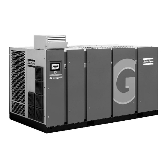
Page 13: General Description
Instruction book General description Introduction General view General view of GA VSD Description of GA VSD compressors GA VSD (Variable Speed Drive) compressors are single-stage, oil-injected screw compressors directly driven by an electric motor. The compressors deliver pulsation-free air. By continuously matching the speed of the drive motor to the air net pressure, the compressor optimizes energy consumption and reduces the operating pressure band.
-
Page 14: Air And Oil System
Instruction book Air and oil system Flow diagrams Flow diagram for air-cooled GA VSD compressors (Energy recovery model year 2007) APF192090…
-
Page 15
Instruction book Flow diagram for air-cooled GA VSD compressors (Energy recovery model year 2014) Drawing Reference Description In parentheses Air outlet Air inlet Condensate drain of the compressor Condensate drain of the dryer APF192090… -
Page 16
Drawing Reference Description Customer’s installation Atlas Copco installation For symbols / linestyles refer to 9823 4059 00 R and Atlas Copco standard 1280 K Flow sheet legend 9823 5075 00 * Options Dryer bypass (see instruction 9823 5091 00)* (10) -
Page 17
Instruction book Rear view of air-cooled GA Air flow Air drawn through filter (AF) is compressed in compressor element (E). Compressed air and oil are discharged through check valve (CV) to air receiver/oil separator (AR) where oil is separated from the compressed air. The air is blown through minimum pressure valve (Vp) to air cooler (Ca). -
Page 18: Cooling And Condensate System
Instruction book In the air receiver (AR) most of the oil is removed from the air centrifugally. Almost all of the remaining oil is removed by the separator element. Cooling and condensate system Condensate drain system Condensate drains of air-cooled GA Automatic condensate drain, compressor Manual condensate drain A condensate trap is installed downstream of the air cooler to prevent condensate from entering the air outlet…
-
Page 19: Elektronikon Regulator
Instruction book Elektronikon regulator Elektronikon control system Main functions In general, the Elektronikon regulator has the following functions: • Controlling the motor speed (Variable Speed Drive), reducing the power consumption and pressure band. • Controlling the speed of the fans of the coolers, reducing the power consumption and noise level. •…
-
Page 20
Instruction book Ref. Designation Load Indirect stop Start (10) Indirect stop offset If the motor is running at minimum speed and the net pressure rises to a value equal to the sum of the programmed pressure set-point and the programmed indirect stop offset, the compressor will stop. When the net pressure drops, the regulator will calculate the optimum moment to restart the compressor to avoid the net pressure decreasing below the pressure set-point (anticipated starting). -
Page 21: Control Panel
The regulator has a built-in function to automatically restart the compressor if the voltage is restored after voltage failure. This function is deactivated in compressors leaving the factory. If desired, the function can be activated. Consult Atlas Copco. If activated and provided the module was in the automatic operation mode, the compressor will automatically restart if the supply voltage to the module is restored within a programmed time period.
-
Page 22: Function Keys
Instruction book Reference Designation Function Tabulator key Key to select the parameter indicated by the horizontal arrow. Only the parameters followed by an arrow pointing to the right can be modified. Function keys Keys to control and program the compressor. Voltage on LED Indicates that the voltage is switched on.
-
Page 23: Scroll Keys
“Cancel” To cancel a programmed setting when programming parameters “Delete” To delete compressor start/stop commands “Help” To find the Atlas Copco internet address “Limits” To show limits for a programmable setting “Load” Not used on VSD (Variable Speed Drive) compressors To load the compressor manually “Mainscreen”…
-
Page 24: Emergency Stop Button
Instruction book Emergency stop button Control panel Description In case of emergency, press button (S2) to stop the compressor immediately. Using the emergency stop breaks the circuit to: • the variable speed drive unit of the drive motor. • on air-cooled compressors, the variable speed drive unit of the fan motors. •…
-
Page 25
Instruction book Menu flow for air-cooled GA 132/160 VSD compressors (simplified example) Program Function Main screen Shows in brief the operational status of the compressor. Is the gateway to all functions. “Status Data” Calls up the status of the compressor protection functions (shut-down, shut-down warning and service warning). -
Page 26: Calling Up Menus
Instruction book Program Function “Counters” Calls up: • running hours • regulator (module) hours • number of motor starts “Test” Display test. “Modify Parameters” Modifying the settings for: • Parameters (e.g. loading and unloading pressures) • Protections (e.g. temperature shut-down level) •…
-
Page 27: Main Screen Menu
Instruction book After pressing the “Menu” (F1) key, the option “Status Data” will be followed by a horizontal arrow: • Either press the tabulator key (2) to select this menu, • or use the arrow down key (1) until the desired submenu is followed by a horizontal arrow and then press the tabulator key (2) to select this menu.
-
Page 28: Status Data Menu
Instruction book • Messages regarding the compressor operating condition • Just above the function keys (3), the actual functions of these keys Status data menu Warning Before starting any maintenance or repairs, press the stop button (4), wait until the compressor has stopped, press the red emergency stop button and open the isolating switch (customer’s installation) to switch off the voltage to the compressor.
-
Page 29
Instruction book “All Conditions Are OK” “Menu” “Help” A shut-down message exists • In case the compressor is shut down, LED (1) will blink. • In case of a shut-down due to too high a temperature at the outlet of the compressor element: “Element Outlet”… -
Page 30
“Status Data” menu to “Inputs” and press the “Reset” key to reset the service message. • In case the service message was referring to “Plan”: carry out the service actions related to the indicated plans. Reset the timers of the related plans. Contact your Atlas Copco Customer Centre. See Service menu. -
Page 31: Measured Data Menu
Instruction book 3.10 Measured data menu Control panel Function To call up information regarding the actually measured data and the status of some inputs such as the motor overload protection. Consult the menu flow in section Control programs. Procedure Starting from the Main screen (see Main screen menu): •…
-
Page 32: Counters Menu
Instruction book 3.11 Counters menu Control panel Function To call up: • The running hours • The loaded hours • The number of motor starts • The number of hours the regulator (module) has been under tension • The number of load cycles Procedure Starting from the Main screen (see Main screen…
-
Page 33: Test Menu
Instruction book 3.12 Test menu Control panel Function To carry out a display test, i.e. to check whether the display and LEDs are still intact. Procedure • Starting from the Main screen (see Main screen menu), press the “Menu” (F1) key. •…
-
Page 34: Modifying Compressor/Motor Settings
Instruction book 3.14 Modifying compressor/motor settings Control panel Function To modify a number of settings. Consult the menu flow in section Control programs. Procedure Starting from the Main screen (see Main screen menu): • Press the key “Menu” (F1). • Press the arrow down key (1) until “Modify parameters” is followed by an arrow pointing to the right. •…
-
Page 35: Fan Motor Settings
Instruction book “Setpoint 1” 7.0 bar “Setpoint 2” 6.0 bar “Indirect Stop Level” 0.3 bar “Menu” “Modify” The regulator will not accept new values beyond the limitations. It is possible to check the limitations which are valid for the parameter to be modified by selecting “Limits”.
-
Page 36: Modifying Parameters
Instruction book “Minimum Speed” 0 “rpm” “Maximum RPM Reduction” 100 “pct” “Menu” “Modify” 3.16 Modifying parameters Function Control panel To modify a number of parameters. Consult the menu flow in section Control programs. Procedure Starting from the Main screen (see Main screen menu): •…
-
Page 37: Modifying Protection Settings
Instruction book The regulator will not accept new values beyond the limitations. Press the key “Limits” to check the limitations for the parameter. Consult Programmable settings for the most important settings. 3.17 Modifying protection settings Control panel Function To modify protection settings: •…
-
Page 38: Modifying Service Plans
Service plans are to be carried out. Always consult your Atlas Copco Customer Centre in case any timer should be changed. The intervals must not exceed the programmed nominal values.
-
Page 39: Programming Clock Function
Instruction book 3.19 Programming clock function Control panel Function To program: • Time-based start/stop commands for the compressor • Time-based change-over commands for the net pressure band Programming start, stop and pressure band commands In this example, the compressor will be programmed as follows: •…
-
Page 40
Instruction book “Monday” “Tuesday” “Wednesday” “Menu” “Delete” • Use the scroll keys (1) until the day on which a command must be programmed is followed by a horizontal arrow. Press the tabulator key (2); following screen appears: —:— ———————- —:— ———————- —:— ———————-… -
Page 41
Instruction book “Clock Function” “Not Activated” “Menu” “Modify” “Delete” • Press the key “Modify”, “Not Activated” starts blinking. • Press the arrow down key (1) “Not Activated” changes to “Activated”. • Press the key “Program”. It is necessary to program the start/stop commands in successive order timewise. Program the commands from Monday till Sunday, e.g.: •… -
Page 42
Instruction book arrow. Press the key “Modify”, the first two digits of the command start blinking. Modify as required using the scroll keys, i.e. in the example above change “18” into “17” using the arrow up key (1). • If necessary, press the tabulator key (2) to go to the next field to be modified, the minutes indication and the start/stop/pressure band indication. -
Page 43: Modifying Configuration Settings
Instruction book Press the arrow down key and add the last command of the list (in the example above “18:00 Stop Compressor” and press the key “Program”. Deleting a command • Starting from the Main screen, press the key “Menu” (F1), press the arrow down key until the option “Modify Parameters”…
-
Page 44
Instruction book Function To modify a number of parameters. Consult the menu flow in section Control programs. Procedure Starting from the Main screen (see Main screen menu): • Press the key “Menu” (F1). • Press the arrow down key (1) until “Modify Parameters” is followed by an arrow pointing to the right. •… -
Page 45: Service Menu
Instruction book 3.21 Service menu Control panel Function • To reset the service plans which are carried out. • To check when the next service plans are to be carried out. • To find out which service plans were carried out previously. Service plans A number of service operations are grouped (called Level A, Level B, etc…).
-
Page 46
Instruction book Procedure Starting from the Main screen (see Main screen menu): • Press the key “Menu” (F1). • Press the arrow down key (1) until “Service” is followed by a horizontal arrow. • Activate the menu by pressing tabulator key (2). •… -
Page 47: Saved Data Menu
Instruction book 3.22 Saved data menu Control panel Function To call up some data saved by the regulator. These data are: • Last shut-down data • Last emergency stop data Procedure Starting from the Main screen (see Main screen menu): •…
-
Page 48
Instruction book Minimum Factory Maximum setting setting setting Proportional band Integration time Minimum motor speed 1500 Maximum rpm reduction Parameters Minimum Factory Maximum setting setting setting Minimum stop time: Permissive start time: Power recovery time (ARAVF) 3600 Restart delay Communication time-out Protections Minimum Factory… -
Page 49
Delay at signal Remark A number of service operations are grouped (Level A, Level B, …). Each level stands for a number of service operations to be carried out at the programmed intervals. Consult your Atlas Copco Service Centre. APF192090… -
Page 50
To activate the automatic restart function, consult Atlas Copco. Delay at shut- Is the time for which the signal must exist before the compressor is shut down. If it is down signal required to program this setting to another value, consult Atlas Copco. APF192090… -
Page 51: Installation
Instruction book Installation Dimension drawing Compressor dimensions Dimension drawing of air-cooled Pack VSD compressors APF192090…
-
Page 52
Instruction book Text on drawing Reference Designation Compressed air outlet Cooling air outlet Compressor air inlet Cooling air inlet Right hand side view Left hand side view Electric cable entry Automatic drain, dryer Rear side view (10) Manual drain (11) Automatic drain (12) Detail X… -
Page 53: Installation Proposal
Instruction book Installation proposal Compressor room example Compressor room example of GA VSD air-cooled compressor Text on drawing APF192090…
-
Page 54
Instruction book Reference Designation Minimum free area to be reserved for compressor installation Ventilation proposals Cooling systems Compressor air outlet, if dryer is by-passed Compressor air outlet, Full-Feature compressors Motor ventilation, air outlet Motor ventilation, air inlet Compressor air inlet Cooling air outlet (10) Dryer cooling air outlet… -
Page 55
Instruction book Phase Description Install the compressor on a level floor suitable for taking its weight. For ventilation alternative 1 (indicated as Alt. 1), the minimum distance between the top of the bodywork and the ceiling is 1200 mm (47.2 in). Remove the plastic plug (if provided) from the compressor air outlet pipe and fit the air outlet valve (to be provided by the customer) to the pipe. -
Page 56: Electric Cable Size And Fuses
The fan capacity should match the compressor fan capacity at a pressure head equal to the pressure drop caused by the cooling air outlet ducts. Consult Atlas Copco. Remove the plastic plugs (if provided) from the condensate outlets and fit the manual condensate drain valve.
-
Page 57: Electric Connections
Electric connections General instruction for the electrical installation of VSD compressors • Electrical equipment from Atlas Copco Compressor is designed in accordance with the safety regulations described in IEC60204-1 and CENELEC EN60204. • It is the responsibility of the customer to install the compressor unit according to the safety regulations in order to protect people from electric shocks from direct or indirect contact.
-
Page 58
Instruction book Atlas Copco strongly recommends that customers do not connect the neutral conductor from the power supply to the compressor unit. The exposed conductive parts of the installation must be earthed locally. (EN 60204-1 par.: 7.2.3) Power distribution systems (TN, TT, IT) According to IEC 60950, there are three main types of power distribution systems: TN, TT and IT. -
Page 59
Instruction book Power system earth Exposed conductive parts Network type TN-C-S (Terra Neutral-Combined-Separate) : In the TN-C-S power distribution system, the neutral and the protective earth functions are combined to some degree in a single conductor, a direct earth to the exposed conductive parts of the installation exists in part. The connection is achieved through the PEN conductor. -
Page 60
Instruction book Power system earth Exposed conductive parts Impedance Ambient conditions The drive must only be used in a heated, indoor and controlled environment. Environmental limits are listed below. Operation Installed for stationary use Air temperature No frost allowed Relative humidity 5 to 95 % No condensation allowed. -
Page 61
Instruction book Electric cabinet Cabinet with VSD (Variable Speed Drive) unit of GA 132/160 VSD APF192090… -
Page 62
Instruction book Electric diagram of GA 132/160 VSD Ref. Designation RFI filter Frequency converter, drive motor Frequency converter, fan motors of air/oil cooler block Frequency converter, compressor motor of dryer F3/5 Circuit breakers, control circuit F17/47 Circuit breakers, condensate circuit Auxiliary relay, motor running indication Contactor, emergency stop Drive motor… -
Page 63
Drive motor of dryer Fan motor of dryer, air-cooled Cable connection for GA 110 VSD, GA 132 VSD and GA 160 VSD Always use cable glands. A plate (1) has to be made by the customer to cover up the hole in the cubicle and to install cable glands. -
Page 64
Instruction book APF192090… -
Page 65: Quality Of Safety Components
Instruction book Cable section Cable diameter Cable gland size AC number 0698 5140 71 0698 5140 71 11.0 0698 5140 72 12.4 0698 5140 73 13.8 0698 5140 73 Quality of safety components When installing a remote emergency button or a motor contactor, the following B10d values are advised: •…
-
Page 66
Instruction book Figure A APF192090… -
Page 67
Instruction book Figure B APF192090… -
Page 68: Installation Instructions For Heavy Duty Filter For Vsd Cubicle
Instruction book Completed assembly of the cubicle fan Installation instructions for heavy duty filter for VSD cubicle Description 1. Remove the original filters (1). Remove the red plates (2). APF192090…
-
Page 69
Instruction book 2. Place the seals (3) on the back side of the box, then install the box to the cubicle door using rivets. The ordering number for the seals is 1619 5188 00. 3. Install the heavy duty filters as shown below. APF192090… -
Page 70
Instruction book Text on figure: APF192090… -
Page 71: Installation Instructions For Dryer By-Pass
Instruction book Cooling air flow Compressor side Outside Installation instructions for dryer by-pass Description It is not required to connect a bypass, a blind flange is foreseen ex factory. If by-passing of the dryer is required, connect the compressor to the air net as shown below. The compressed air outlet temperature sensor (G3/8”) and the pressure transducer (1/4”…
-
Page 72
Instruction book Shut-off valve, air net By-pass valve, compressor By-pass valve, dryer New location for temperature sensor and pressure transducer Pipe towards air net Nipple APF192090… -
Page 73: Installation Instructions Gsm Alarm
Instruction book Installation instructions GSM alarm Hardware installation Fix the Air contact module (1) to the rail as shown below. Assemble the power supply cable, using: • connector X150.3 (ordering number 1088 0037 64) • two power wires (ordering number 0017 2010 40) •…
-
Page 74
Instruction book The antenna must be led to the outside of the cubicle. The antenna cable can be led through a present conduit gland (preferably the gland which contains the Electronic drain cables) or a grommet can be used in a closed hole. -
Page 75
Instruction book Software installation For software installation please contact your local Atlas Copco service center. APF192090… -
Page 76: Pictographs
Instruction book 4.10 Pictographs Explanation of Pictographs Pictographs at other locations Ref. Designation Start Scroll keys Tabulator key Function keys Voltage on Alarm Automatic operation Stop Automatic condensate drain Manual condensate drain Stop the compressor before maintenance or repair Warning: under tension Read Instruction book before starting the compressor Switch off the voltage and depressurise the compressor before maintenance or repair Before connecting the compressor electrically, consult the instruction manual for the motor…
-
Page 77
Instruction book Ref. Designation Do not mix oil brands APF192090… -
Page 78: Operating Instructions
Outdoor/altitude operation If the compressor is installed outdoors or if the air inlet temperature can be below freezing point, precautions must be taken. In this case, and also if operating at high altitude, consult Atlas Copco. Moving/lifting The compressor can be moved by a lift truck using the slots in the frame. Make sure that the forks protrude from the other side of the frame.
-
Page 79
If the rotation direction is wrong, press the emergency stop button, switch off the voltage and reverse two incoming electric lines. If the rotation direction of the fan motor is wrong, consult your Atlas Copco customer centre. Run the compressor for a few minutes and check that it is operating normally. -
Page 80: Before Starting
Instruction book Before starting Warning Step Action The operator must apply all relevant safety precautions. See the section Safety precautions. Switch off your mobile phone when in the vicinity of a GA VSD compressor which is under tension. Procedure Step Action Switch on the voltage.
-
Page 81: During Operation
Instruction book Step Action Press start button (1). The compressor starts running and automatic operation LED (3) lights up. During operation Description When automatic operation LED (3) is lit, the Elektronikon regulator is automatically controlling the compressor: the speed will continuously vary to match the air delivery to the air consumption, and the compressor will start and stop whenever necessary.
-
Page 82
Example of the main menu “Status data” “Measured Data” “Counters” “Mainscreen” Example of the main display Example of Main screen of GA 110 VSD up to GA 160 VSD compressors “Compressor Outlet” 7.5 bar “Compressor Speed” 2100 rpm “Menu” APF192090… -
Page 83: Stopping
Action Press stop button (1): the compressor will stop and LED (2) will go out. To stop the GA 110 VSD up to GA 160 VSD compressor in the event of an emergency, press the emergency stop button (S2). Close air outlet valve.
-
Page 84: Use Of Air Receiver
Instruction book Use of air receiver Instructions Step Action This equipment can contain pressurised air and oil; be aware of its potential danger if used improperly. This equipment must only be used as compressed air/oil separator and must be operated within the specified limits.
-
Page 85: Maintenance
Instruction book Maintenance Preventive maintenance schedule Warning Before carrying out any maintenance, repair work or adjustment, proceed as follows: • Stop the compressor. Press emergency stop button (S2). • • Close the air outlet valve and open the manual condensate drain valves. •…
-
Page 86: Motors
Elektronikon regulator. When a level is reached, a message will appear on the screen. After carrying out all service actions, the interval timers must be reset using the “Reset” key in the “Service” menu. Consult your Atlas Copco Service Centre. Motors Warning Stop the compressor and switch off the voltage.
-
Page 87: Oil Specifications
Oil specifications Atlas Copco Roto-Xtend Duty Fluid Atlas Copco Roto-Xtend Duty Fluid is a high-quality synthetic lubricant for oil-injected scroll and screw compressors which keeps the compressor in excellent condition. Roto-Xtend Duty Fluid can be used for compressors operating at ambient temperatures between 0 ˚C (32 ˚F) and 46 ˚C (115 ˚F) (see section Service kits).
-
Page 88
Instruction book Procedure 1. Run the compressor until warm. Stop the compressor, close the air outlet valve and switch off the voltage. Wait a few minutes and depressurize by unscrewing the vent plug on top of the air receiver to permit any pressure in the system to escape. -
Page 89
Instruction book 1. Take off the side panels of the compressor and remove the stays. 2. Open the cooler compartment and disconnect the cooler inlet pipe (1). 3. Disconnect the cooler outlet pipe (4) and roll out the oil cooler (2). 4. -
Page 90
Instruction book Draining the compressor element, oil filter housing and oil stop valve 1. Remove the drain plug (3) to drain the oil stop valve. 2. Remove the drain plug of the flexible to drain the oil from the gearbox. 3. -
Page 91: Storage After Installation
Service kits General Service kits comprise all parts needed for servicing components and offer the benefits of genuine Atlas Copco parts while keeping the maintenance budget low. All service kits are indicated in the relevant Parts Lists. Atlas Copco Roto-Xtend Duty Fluid Roto-Xtend Duty Fluid can be ordered in the following quantities: •…
-
Page 92
Instruction book Oil specifications. APF192090… -
Page 93: Dd Filter
Instruction book DD filter Maintenance When maintaining the filter, keep in mind the following: • On filters with manual drain valve, open the latter at regular intervals to evacuate collected dust or liquid • Change the filter element yearly or when the pressure drop reaches approx. 0.35 bar •…
-
Page 94: Filter Disposal
Instruction book 4. Discard the old filter element. 5. Remove the O-ring from the bowl and clean the bowl with isopropanol. Cleaning cloths of Kimtech are recommended. Position a new O-ring on the bowl. 6. Open the sealed bag at the topcap side of the filter cartridge. 7.
-
Page 95: Integrated Dryer
Instruction book Integrated dryer Condensate drain system Description The condensate enters the Electronic Water Drain (EWD) via inlet (1) and accumulates in the water separator of the heat exchanger and in collector (2). A capacitive sensor (3) continuously measures the liquid level. As soon as the collector is filled up to a certain level, a drain delay timer is started.
-
Page 96: Maintenance Instructions
Instruction book Testing the Electronic water drain Control panel, EWD Briefly press the TEST button and check that the valve opens for condensate discharge. Checking the alarm signal • Press and hold the test button for at least 1 minute. •…
-
Page 97: Problem Solving
Instruction book Warranty and product liability Use only Atlas Copco authorized genuine parts. Any damage or malfunction caused by the use of unauthorized parts is not covered by Warranty or Product Liability. General The following remarks should be kept in mind: •…
-
Page 98: Adjustments And Servicing Procedures
Instruction book Adjustments and servicing procedures Air filters Warning Stop the compressor, close the air outlet valve, press the emergency stop button and switch off the voltage. The operator must apply all relevant Safety precautions. Control panel of MkIV regulator Control panel of MkIV regulator APF192090…
-
Page 99
Instruction book Position of air filter Procedure Step Action Remove panel (4) from the compressor. Remove the filter element. Fit the new filter element. Reinstall panel (4) Reset the message and service timer: Press the “Menu” key (3). • Press key (1) until “Service” is followed by an arrow pointing to the right. Activate the •… -
Page 100: Coolers
Instruction book Coolers Checking the coolers for cleanliness on air-cooled compressors Activate the «Cleanlinesstest» option in the Elektronikon regulator as follows: • Starting from the main screen, press the «Menu» key. • Press the arrow down key (1) until «Test» is followed by a horizontal arrow. •…
-
Page 101
Clean the coolers with an air jet in the reverse direction to normal flow. Use low pressure air; if necessary, the pressure may be increased up to 6 bar (e) (87 psig) If it is necessary to clean the coolers with a cleaning agent, consult Atlas Copco. Close the inside doors. -
Page 102: Safety Valve
No adjustments are allowed. Testing The valve can be tested on a separate compressed air line. Consult the Atlas Copco Customer Centre if the valve does not open at the correct pressure (see the section Settings of safety valve). APF192090…
-
Page 103: Problem Solving
Instruction book Problem solving 10.1 Problem solving Warning Before carrying out any maintenance, repair work or adjustment, stop the compressor, press the emergency stop button and switch off the voltage. Close the air outlet valve and open the manual condensate drain valves. Open and lock the isolating switch.
-
Page 104
“Reset” key (2); the message “All protection functions are OK” will appear, after which the compressor can be restarted. Excessive oil consumption Have the compressor inspected by the Atlas Copco Customer Centre. Condition Fault Remedy… -
Page 105: Technical Data
Instruction book Technical data 11.1 Readings on display General Control panel Reference Units Reading Outlet pressure bar(e) Depends on pressure set-point Speed Varies (controlled by regulator) Maximum working pressure bar(e) Compressor data. At pressure set-point Reference Units 4 bar(e) 7 bar(e) 9.5 bar(e) 13.5 bar(e) Dp of air filter, approx.
-
Page 106: Reference Conditions
Instruction book 11.2 Reference conditions Reference conditions Absolute inlet pressure bar(a) Relative air humidity Air inlet temperature ˚C Nominal working pressure See Compressor data Cooling medium inlet temperature ˚C 11.3 Limits Limits Maximum air inlet/ambient temperature, GA 110 VSD up to GA ˚C 160 VSD Minimum air inlet/ambient temperature…
-
Page 107: Compressor Data
TT/TN CSA/UL CSA/UL 2.,5 CSA/UL 11.6 Compressor data Data for GA 125 psi (8.6 bar) 60 Hz compressors Units GA 160 VSD Maximum working pressure, GA Pack bar(e) Nominal working pressure bar(e) Motor shaft speed for: Pack compressors r/min 2779…
-
Page 108: Pressure Equipment Directives
Pressure equipment directives Category IV Product: • GA 160 VSD This machine is a pressure assembly of cat. IV according to 97/23/EC. Parts of article 3.3 of 97/23/EC are subject to good engineering practice. Parts of category I according to 97/23/EC are integrated into the machine and fall under the exclusion of article I, section 3.6.
-
Page 109
Instruction book Reference Description Cover serial number here Data plate here Minimum wall thickness after corrosion of the vessel 5.5mm (0.216 in) Minimum wall thickness after corrosion of the cover 8 mm (0.315 in) Lifetime infinite according to AD2000-S1 § 4.2.2. Delta p 7.5 bar (108.8 psi) Casting factor cover… -
Page 110: Documentation
Instruction book Documentation Declaration of conformity Typical example of a Declaration of Conformity document APF192090…
-
Page 112
Not for the sake of technology, but for the sake of our customer’s bottom line and peace-of-mind. That is how Atlas Copco will strive to remain the first choice, to succeed in attracting new business and to maintain our position as the industry leader.

GA 110 VSD, GA 132 VSD, GA 160 VSD
Instruction book
Atlas Copco
GA 110 VSD, GA 132 VSD, GA 160 VSD
Instruction book
Original instructions
Copyright Notice
Any unauthorized use or copying of the contents or any part thereof is prohibited.
This applies in particular to trademarks, model denominations, part numbers and drawings.
This instruction book is valid for CE as well as non-CE labelled machines. It meets the
requirements for instructions specified by the applicable European directives as identified
in the Declaration of Conformity.
2011 - 07
No. 2920 1728 05
www.atlascopco.com
Instruction book
Table of contents
1
Safety precautions..........................................................................................................6
1.1
SAFETY ICONS...................................................................................................................................6
1.2
SAFETY PRECAUTIONS, GENERAL...........................................................................................................6
1.3
SAFETY PRECAUTIONS DURING INSTALLATION...........................................................................................6
1.4
SAFETY PRECAUTIONS DURING OPERATION..............................................................................................8
1.5
SAFETY PRECAUTIONS DURING MAINTENANCE OR REPAIR...........................................................................9
2
General description......................................................................................................11
2.1
INTRODUCTION.................................................................................................................................11
2.2
AIR AND OIL SYSTEM.........................................................................................................................13
2.3
COOLING AND CONDENSATE SYSTEM....................................................................................................17
2.4
ENERGY RECOVERY SYSTEM...............................................................................................................18
3
Elektronikon regulator.................................................................................................40
3.1
ELEKTRONIKON CONTROL SYSTEM.......................................................................................................40
3.2
CONTROL PANEL..............................................................................................................................42
3.3
FUNCTION KEYS...............................................................................................................................43
3.4
SCROLL KEYS..................................................................................................................................44
3.5
EMERGENCY STOP BUTTON................................................................................................................45
3.6
CONTROL PROGRAMS........................................................................................................................46
3.7
CALLING UP MENUS..........................................................................................................................48
3.8
MAIN SCREEN MENU.........................................................................................................................49
3.9
STATUS DATA MENU..........................................................................................................................50
3.10
MEASURED DATA MENU.....................................................................................................................53
3.11
COUNTERS MENU.............................................................................................................................54
3.12
TEST MENU.....................................................................................................................................55
3.13
MODIFY PARAMETERS.......................................................................................................................55
3.14
MODIFYING COMPRESSOR/MOTOR SETTINGS..........................................................................................56
2
2920 1728 05
Instruction book
3.15
FAN MOTOR SETTINGS.......................................................................................................................57
3.16
MODIFYING DRYER MOTOR SETTINGS....................................................................................................58
3.17
MODIFYING PARAMETERS...................................................................................................................59
3.18
MODIFYING PROTECTION SETTINGS......................................................................................................60
3.19
MODIFYING SERVICE PLANS................................................................................................................61
3.20
PROGRAMMING CLOCK FUNCTION.........................................................................................................62
3.21
MODIFYING CONFIGURATION SETTINGS..................................................................................................67
3.22
SERVICE MENU................................................................................................................................68
3.23
SAVED DATA MENU...........................................................................................................................70
3.24
PROGRAMMABLE SETTINGS.................................................................................................................71
4
Installation.....................................................................................................................76
4.1
DIMENSION DRAWING........................................................................................................................76
4.2
INSTALLATION PROPOSAL...................................................................................................................80
4.3
ELECTRIC CABLE SIZE AND FUSES........................................................................................................86
4.4
ELECTRIC CONNECTIONS....................................................................................................................91
4.5
INSTALLATION INSTRUCTIONS FOR CUBICLE FAN....................................................................................100
4.6
INSTALLATION INSTRUCTIONS FOR HEAVY DUTY FILTER FOR VSD CUBICLE................................................103
4.7
INSTALLATION INSTRUCTIONS FOR DRYER BY-PASS ...............................................................................106
4.8
INSTALLATION INSTRUCTIONS GSM ALARM..........................................................................................108
4.9
PICTOGRAPHS...............................................................................................................................111
4.10
COOLING WATER REQUIREMENTS.......................................................................................................112
5
Operating instructions...............................................................................................116
5.1
INITIAL START-UP............................................................................................................................116
5.2
BEFORE STARTING..........................................................................................................................118
5.3
STARTING.....................................................................................................................................119
5.4
DURING OPERATION........................................................................................................................120
5.5
CHECKING THE DISPLAY...................................................................................................................121
5.6
STOPPING.....................................................................................................................................122
2920 1728 05
3
Instruction book
5.7
TAKING OUT OF OPERATION..............................................................................................................123
5.8
USE OF AIR RECEIVER.....................................................................................................................123
6
Maintenance................................................................................................................125
6.1
PREVENTIVE MAINTENANCE SCHEDULE................................................................................................125
6.2
MOTORS.......................................................................................................................................126
6.3
OIL SPECIFICATIONS........................................................................................................................127
6.4
OIL CHANGE..................................................................................................................................127
6.5
STORAGE AFTER INSTALLATION.........................................................................................................132
6.6
SERVICE KITS................................................................................................................................132
7
DD filter........................................................................................................................133
7.1
MAINTENANCE...............................................................................................................................133
7.2
FILTER ELEMENT CHANGE ................................................................................................................133
7.3
SERVICE INTERVALS........................................................................................................................134
7.4
FILTER DISPOSAL............................................................................................................................134
7.5
REFERENCE CONDITIONS.................................................................................................................134
7.6
PRINCIPAL DATA.............................................................................................................................134
8
Integrated dryer..........................................................................................................135
8.1
CONDENSATE DRAIN SYSTEM............................................................................................................135
8.2
MAINTENANCE INSTRUCTIONS...........................................................................................................136
8.3
PROBLEM SOLVING.........................................................................................................................137
9
Adjustments and servicing procedures...................................................................139
9.1
AIR FILTERS..................................................................................................................................139
9.2
COOLERS.....................................................................................................................................141
9.3
SAFETY VALVE...............................................................................................................................143
10
Problem solving..........................................................................................................145
4
2920 1728 05
Instruction book
10.1
PROBLEM SOLVING.........................................................................................................................145
11
Technical data.............................................................................................................147
11.1
READINGS ON DISPLAY....................................................................................................................147
11.2
REFERENCE CONDITIONS.................................................................................................................148
11.3
LIMITS..........................................................................................................................................148
11.4
SETTINGS OF SAFETY VALVE.............................................................................................................149
11.5
SETTINGS OF CIRCUIT BREAKERS.......................................................................................................150
11.6
COMPRESSOR DATA........................................................................................................................150
12
Pressure equipment directives.................................................................................160
13
Documentation............................................................................................................161
2920 1728 05
5
Instruction book
1
Safety precautions
1.1
Safety icons
Explanation
Danger for life
Warning
Important note
1.2
Safety precautions, general
General precautions
1. The operator must employ safe working practices and observe all related work safety requirements and
regulations.
2. If any of the following statements does not comply with the applicable legislation, the stricter of the two
shall apply.
3. Installation, operation, maintenance and repair work must only be performed by authorized, trained,
specialized personnel.
4. The compressor is not considered capable of producing air of breathing quality. For air of breathing quality,
the compressed air must be adequately purified according to the applicable legislation and standards.
5. Before any maintenance, repair work, adjustment or any other non-routine checks, stop the compressor,
press the emergency stop button, switch off the voltage and depressurize the compressor. In addition, the
power isolating switch must be opened and locked.
On units powered by a frequency converter, wait six minutes before starting any electrical repair.
6. Never play with compressed air. Do not apply the air to your skin or direct an air stream at people. Never
use the air to clean dirt from your clothes. When using the air to clean equipment, do so with extreme
caution and wear eye protection.
7. The owner is responsible for maintaining the unit in safe operating condition. Parts and accessories shall
be replaced if unsuitable for safe operation.
8. It is not allowed to walk or stand on the roof of the unit.
1.3
Safety precautions during installation
All responsibility for any damage or injury resulting from neglecting these precautions, or
non observance of the normal caution and care required for installation, operation,
maintenance and repair, even if not expressly stated, will be disclaimed by the
manufacturer.
6
2920 1728 05
Instruction book
Precautions during installation
1. The machine must only be lifted using suitable equipment in accordance with the applicable safety
regulations. Loose or pivoting parts must be securely fastened before lifting. It is strictly forbidden to
dwell or stay in the risk zone under a lifted load. Lifting acceleration and deceleration must be kept within
safe limits. Wear a safety helmet when working in the area of overhead or lifting equipment.
2. Place the machine where the ambient air is as cool and clean as possible. If necessary, install a suction
duct. Never obstruct the air inlet. Care must be taken to minimize the entry of moisture at the inlet air.
3. Any blanking flanges, plugs, caps and desiccant bags must be removed before connecting the pipes.
4. Air hoses must be of correct size and suitable for the working pressure. Never use frayed, damaged or
worn hoses. Distribution pipes and connections must be of the correct size and suitable for the working
pressure.
5. The aspirated air must be free of flammable fumes, vapours and particles, e.g. paint solvents, that can lead
to internal fire or explosion.
6. Arrange the air intake so that loose clothing worn by people cannot be sucked in.
7. Ensure that the discharge pipe from the compressor to the aftercooler or air net is free to expand under
heat and that it is not in contact with or close to flammable materials.
8. No external force may be exerted on the air outlet valve; the connected pipe must be free of strain.
9. If remote control is installed, the machine must bear a clear sign stating: DANGER: This machine is
remotely controlled and may start without warning.
The operator has to make sure that the machine is stopped and that the isolating switch is open and locked
before any maintenance or repair. As a further safeguard, persons switching on remotely controlled
machines shall take adequate precautions to ensure that there is no one checking or working on the
machine. To this end, a suitable notice shall be affixed to the start equipment.
10. Air-cooled machines must be installed in such a way that an adequate flow of cooling air is available and
that the exhausted air does not recirculate to the compressor air inlet or cooling air inlet.
11. The electrical connections must correspond to the applicable codes. The machines must be earthed and
protected against short circuits by fuses in all phases. A lockable power isolating switch must be installed
near the compressor.
12. On machines with automatic start/stop system or if the automatic restart function after voltage failure is
activated, a sign stating "This machine may start without warning" must be affixed near the instrument
panel.
13. In multiple compressor systems, manual valves must be installed to isolate each compressor. Non-return
valves (check valves) must not be relied upon for isolating pressure systems.
14. Never remove or tamper with the safety devices, guards or insulation fitted on the machine. Every pressure
vessel or auxiliary installed outside the machine to contain air above atmospheric pressure must be
protected by a pressure relieving device or devices as required.
15. Piping or other parts with a temperature in excess of 80˚C (176˚F) and which may be accidentally touched
by personnel in normal operation must be guarded or insulated. Other high temperature piping must be
clearly marked.
16. For water-cooled machines, the cooling water system installed outside the machine has to be protected by
a safety device with set pressure according to the maximum cooling water inlet pressure.
17. If the ground is not level or can be subject to variable inclination, consult the manufacturer.
Also consult following safety precautions: Safety precautions during operation and Safety
precautions during maintenance.
These precautions apply to machinery processing or consuming air or inert gas.
Processing of any other gas requires additional safety precautions typical to the application
which are not included herein.
Some precautions are general and cover several machine types and equipment; hence
some statements may not apply to your machine.
2920 1728 05
7
Instruction book
1.4
Safety precautions during operation
All responsibility for any damage or injury resulting from neglecting these precautions, or
non observance of the normal caution and care required for installation, operation,
maintenance and repair, even if not expressly stated, will be disclaimed by the
manufacturer.
Precautions during operation
1. Never touch any piping or components of the compressor during operation.
2. Use only the correct type and size of hose end fittings and connections. When blowing through a hose or
air line, ensure that the open end is held securely. A free end will whip and may cause injury. Make sure
that a hose is fully depressurized before disconnecting it.
3. Persons switching on remotely controlled machines shall take adequate precautions to ensure that there
is no one checking or working on the machine. To this end, a suitable notice shall be affixed to the remote
start equipment.
4. Never operate the machine when there is a possibility of taking in flammable or toxic fumes, vapors or
particles.
5. Never operate the machine below or in excess of its limit ratings.
6. Keep all bodywork doors shut during operation. The doors may be opened for short periods only, e.g. to
carry out routine checks. Wear ear protectors when opening a door.
On compressors without bodywork, wear ear protection in the vicinity of the machine.
7. People staying in environments or rooms where the sound pressure level reaches or exceeds 80 dB(A)
shall wear ear protectors.
8. Periodically check that:
• All guards are in place and securely fastened
• All hoses and/or pipes inside the machine are in good condition, secure and not rubbing
• There are no leaks
• All fasteners are tight
• All electrical leads are secure and in good order
• Safety valves and other pressure relief devices are not obstructed by dirt or paint
• Air outlet valve and air net, i.e. pipes, couplings, manifolds, valves, hoses, etc. are in good repair, free
of wear or abuse
9. If warm cooling air from compressors is used in air heating systems, e.g. to warm up a workroom, take
precautions against air pollution and possible contamination of the breathing air.
10. Do not remove any of, or tamper with, the sound-damping material.
11. Never remove or tamper with the safety devices, guards or insulations fitted on the machine. Every pressure
vessel or auxiliary installed outside the machine to contain air above atmospheric pressure shall be
protected by a pressure relieving device or devices as required.
Also consult following safety precautions: Safety precautions during installation and Safety
precautions during maintenance.
These precautions apply to machinery processing or consuming air or inert gas.
Processing of any other gas requires additional safety precautions typical to the application
which are not included herein.
Some precautions are general and cover several machine types and equipment; hence
some statements may not apply to your machine.
8
2920 1728 05
Instruction book
1.5
Safety precautions during maintenance or repair
All responsibility for any damage or injury resulting from neglecting these precautions, or
non observance of the normal caution and care required for installation, operation,
maintenance and repair, even if not expressly stated, will be disclaimed by the
manufacturer.
Precautions during maintenance or repair
1.
2.
3.
4.
5.
6.
7.
8.
9.
10.
11.
12.
13.
14.
15.
16.
17.
18.
19.
20.
21.
Always use the correct safety equipment (such as safety glasses, gloves, safety shoes, etc.).
Use only the correct tools for maintenance and repair work.
Use only genuine spare parts.
All maintenance work shall only be undertaken when the machine has cooled down.
A warning sign bearing a legend such as "Work in progress; do not start" shall be attached to the starting
equipment.
Persons switching on remotely controlled machines shall take adequate precautions to ensure that there
is no one checking or working on the machine. To this end, a suitable notice shall be affixed to the remote
start equipment.
Close the compressor air outlet valve before connecting or disconnecting a pipe.
Before removing any pressurized component, effectively isolate the machine from all sources of pressure
and relieve the entire system of pressure.
Never use flammable solvents or carbon tetrachloride for cleaning parts. Take safety precautions against
toxic vapours of cleaning liquids.
Scrupulously observe cleanliness during maintenance and repair. Keep dirt away by covering the parts
and exposed openings with a clean cloth, paper or tape.
Never weld or perform any operation involving heat near the oil system. Oil tanks must be completely
purged, e.g. by steam cleaning, before carrying out such operations. Never weld on, or in any way modify,
pressure vessels.
Whenever there is an indication or any suspicion that an internal part of a machine is overheated, the
machine shall be stopped but no inspection covers shall be opened before sufficient cooling time has
elapsed; this to avoid the risk of spontaneous ignition of the oil vapour when air is admitted.
Never use a light source with open flame for inspecting the interior of a machine, pressure vessel, etc.
Make sure that no tools, loose parts or rags are left in or on the machine.
All regulating and safety devices shall be maintained with due care to ensure that they function properly.
They may not be put out of action.
Before clearing the machine for use after maintenance or overhaul, check that operating pressures,
temperatures and time settings are correct. Check that all control and shut-down devices are fitted and that
they function correctly. If removed, check that the coupling guard of the compressor drive shaft has been
reinstalled.
Every time the separator element is renewed, examine the discharge pipe and the inside of the oil separator
vessel for carbon deposits; if excessive, the deposits should be removed.
Protect the motor, air filter, electrical and regulating components, etc. to prevent moisture from entering
them, e.g. when steam cleaning.
Make sure that all sound-damping material and vibration dampers, e.g. damping material on the bodywork
and in the air inlet and outlet systems of the compressor, is in good condition. If damaged, replace it by
genuine material from the manufacturer to prevent the sound pressure level from increasing.
Never use caustic solvents which can damage materials of the air net, e.g. polycarbonate bowls.
The following safety precautions are stressed when handling refrigerant:
• Never inhale refrigerant vapours. Check that the working area is adequately ventilated; if required, use
breathing protection.
2920 1728 05
9
Instruction book
• Always wear special gloves. In case of refrigerant contact with the skin, rinse the skin with water. If
liquid refrigerant contacts the skin through clothing, never tear off or remove the latter; flush
abundantly with fresh water over the clothing until all refrigerant is flushed away; then seek medical
first aid.
Also consult following safety precautions: Safety precautions during installation and Safety
precautions during operation.
These precautions apply to machinery processing or consuming air or inert gas.
Processing of any other gas requires additional safety precautions typical to the application
which are not included herein.
Some precautions are general and cover several machine types and equipment; hence
some statements may not apply to your machine.
10
2920 1728 05
Instruction book
2
General description
2.1
Introduction
General view
General view of GA VSD
Description of GA VSD compressors
GA VSD (Variable Speed Drive) compressors are single-stage, oil-injected screw compressors directly driven
by an electric motor. The compressors deliver pulsation-free air. By continuously matching the speed of the
drive motor to the air net pressure, the compressor optimizes energy consumption and reduces the operating
pressure band.
GA VSD compressors are air-cooled.
GA W VSD compressors are water-cooled.
The following features are available as an option:
Full-Feature
A refrigerant dryer is fully integrated into the bodywork of the compressor. This All-in-one feature reduces
the required space for installation and provides savings on piping installation costs.
2920 1728 05
11
Instruction book
DD filter
The compressor is provided with an integrated filter of the DD type to limit carry-over of solid particles and
oil. By integrating a DD filter, the compressor delivers Quality Air according to ISO 8573-1, Class 2.4.2.
Energy recovery
The compressor is provided with an Atlas Copco energy recovery system to recover the major part of the
compression heat in the form of hot water without any influence on the compressor performance.
High ambient temperature (HAT)
The compressor is specially designed for continuous operation under humid and high ambient temperature
conditions. The maximum ambient temperature is:
• 50 ˚C (122 ˚F) for GA Full Feature and GA Full Feature with DD filter
• 55 °C (131 °F) for GA Pack
Roto-Xtend Duty Fluid
Roto-Xtend Duty Fluid is a special, long-life lubricant for GA oil-injected screw compressors. It provides
better cooling and extends the oil change interval.
SPM monitoring
A number of vibration sensors are provided on the drive motor and compressor elements. The readings can
be called up on the display of the Elektronikon regulator.
Anchor pads
Steel plates, fitting in the forklift slots, and bolts are shipped loose with the compressor. With these plates
and bolts, the compressor frame can be fixed to the floor.
Automatic water shut-off
A water shut-off valve is provided in the cooling water system to shut off the system when the compressor is
not in operation.
GSM alarm
The compressor is equipped with a device that is able to send SMS messages or emails to one or more predefined cell phones via a built-in modem at pre-defined events to give information about the status of the
monitored equipment involved.
Heavy duty filter for VSD cubicle
A heavy-duty filter is provided to allow the compressor to operate in heavily contaminated surroundings (e.g.
cement or mining industry).
12
2920 1728 05
Instruction book
2.2
Air and oil system
Flow diagrams
Flow diagram for air-cooled GA VSD compressors
2920 1728 05
13
Instruction book
Flow diagram for water-cooled GA VSD compressors
Position of components
Main components
14
2920 1728 05
Instruction book
Rear view of air-cooled GA
2920 1728 05
15
Instruction book
Rear view of water-cooled GA
Air flow
Air drawn through filter (AF) is compressed in compressor element (E). Compressed air and oil are discharged
through check valve (CV) to air receiver/oil separator (AR) where oil is separated from the compressed air.
The air is blown through minimum pressure valve (Vp) to air cooler (Ca).
On GA Pack compressors, the cooled air is discharged through condensate trap (MTa) and outlet (AOw)
towards the air net.
On GA Full-Feature compressors, the cooled air is discharged through condensate trap (MTa) and outlet
(AOd) towards the air net via the integrated air dryer.
Check valve (CV) prevents blow-back of compressed air.
Minimum pressure valve (Vp) prevents the receiver pressure from dropping below a minimum pressure. The
valve has a built-in check valve.
Oil system
Air pressure forces the oil from receiver (AR) through oil cooler (Co), filters (OF), oil stop valve (Vs) and an
oil injection valve to the compressor element (E) and the lubrication points. The oil injection valve will open
at higher ambient temperatures to keep the element outlet temperature low.
A by-pass valve by-passes the oil cooler (Co) when the injection pressure is low, to ensure a sufficient initial
oil flow to the element when starting the compressor or when switching from unload to load.
For air-cooled units, the oil temperature is controlled by regulating the speed of the fans (FN), to avoid
overcooling and consequently condensation in the air receiver (AR).
16
2920 1728 05
Instruction book
On air-cooled compressors with energy recovery or water-cooled compressors, the oil temperature is
controlled by a thermostatic or electronic valve to avoid overcooling and consequently condensation in the
air receiver (AR).
In the air receiver (AR) most of the oil is removed from the air centrifugally. Almost all of the remaining oil
is removed by the separator element.
2.3
Cooling and condensate system
Condensate drain system
Condensate drains of air-cooled GA
Condensate drains of water-cooled GA
Dac
Automatic condensate drain, compressor
Dad
Automatic condensate drain, dryer (Full-Feature compressors only)
Daf
Automatic condensate drain, DD filter (option)
Dmc
Manual condensate drain
2920 1728 05
17
Instruction book
A condensate trap is installed downstream of the air cooler to prevent condensate from entering the air outlet
pipe. The trap is provided with a float valve for automatically draining condensate and with a manual drain
valve.
On Full-Feature compressors a condensate trap is also installed downstream of the dryer. This trap is also
provided with a float valve for automatically draining condensate.
Cooling system
On air-cooled compressors, the air and oil coolers are cooled by fans.
Water-cooled compressors are provided with a cooling water system, including combined oil and air coolers.
2.4
Energy recovery system
General description
The maximum allowed pressure at the water side of the heat exchanger is 10 bar (145 psi).
The energy required in any compression process is mainly transformed into heat. The major part of the
compression heat is dissipated through the oil system. The Atlas Copco energy recovery systems are designed
to recover most of the above-mentioned heat as warm or hot water without any adverse influence on the
compressor performance.
After the compression stage, the oil is separated from the compressed air. The compressed air flows to the
aftercooler and the oil flows to the oil cooler. The energy in the oil can be recovered by installing a heat
exchanger in front of the oil cooler.
The energy recovery systems can be applied as low temperature rise / high water flow systems (e.g. central
heating in closed water circuits) or as high temperature rise / low water flow systems (e.g. pre-heating of
boiler feed water in open water circuits).
Main components
The system mainly comprises:
•
•
•
•
•
Oil/water heat exchanger (HE)
Energy recovery valve (Y152)
Oil by-pass valve (Y151)
Temperature sensors for water inlet and outlet
The necessary pipes, brackets, bolts, etc.
Installation
The package includes:
• a general by-pass system, to shut down the energy recovery system
• a by-pass system to prevent the oil outlet temperature from dropping below the minimum value.
When the Energy Recovery system is working, this by-pass system makes the oil flow through the Energy
Recovery heat exchanger instead of the normal oil cooler
18
2920 1728 05
Instruction book
Energy recovery system
Pressure drop, water side
Text on figure
(1)
Pressure drop (kPa)
(2)
Pressure drop (bar)
(3)
Water flow (l/s)
For GA 90-132:
• pd = 6.96 F2 + 2.71 F
For GA 160:
• pd = 4.23 F2 + 1.62 F
With:
• pd = pressure drop in kPa
• F = water flow in L/s
The pressure drops calculated with the formulas above are indicative.
2920 1728 05
19
Instruction book
Flow diagram
The recovery water enters the unit at the heat exchanger inlet connection (Wi). In the heat exchanger the
compression heat is transferred from the compressor to the water. The water leaves the heat exchanger via
the outlet connection (Wo).
Installation
The compressor frame is prepared for the Energy Recovery system. Before mounting the installation, the two
laser prepared holes in the frame must be cut out.
20
2920 1728 05
Instruction book
Air-cooled compressors
2920 1728 05
21
Instruction book
Water-cooled compressors
Operation
The compressor oil flow is controlled by two by-pass valves (Y152 and Y151 ), ensuring reliable compressor
operation and optimum energy recovery.
Recoverable Energy
The graphs of section Principal data below represent the performance for each power variant of GA90-160+
at reference working pressure. The curves represent the limits of the energy recovery area and were obtained
with the temperature of the element outlet as indicated in the graph. All points below the curve with Tc=85
°C are possible working points where the recovered energy is maximized for lower element outlet
temperatures.
The formula to calculate the amount of recovered energy is:
Q (kW) = 4.2 x q (l/s) x dT (°C)
with
• q = water flow in l/s
• dT = temperature difference between water at inlet and outlet
For a VSD compressor, when running at a lower motor speed, the recoverable energy will be lower, because
the dT that can be reached is smaller. This can be calculated by using the graph for maximum speed (see
“performance curves”) and then recalculating the dT:
22
2920 1728 05
Instruction book
dTv=dT x (RPMv/RPMmax)
dTv = the lower temperature rise that can be reached at lower motor speed
RPMv = the lower motor speed
RPMmax = the maximum motor speed that can be reached by the GA VSD
Settings
The compressor should never be running in “lowest dewpoint mode”. (See section Modifying fan motor
settings). The vessel temperature setting has to be set by an Atlas Copco service technician.
Regulation
The element outlet temperature must always be higher than the condensation temperature. (see section
Starting). The software in the Elektronikon regulator of GA90-160+ compressors prevents the outlet
temperature of the compressor element from dropping below the condensation temperature. Electronic valve
(Y152) will be used to switch the Energy Recovery system on or off and to regulate the energy recovery.
Electronic valve (Y151) is used to regulate the oil flow through the heat exchangers and consequently the
compressor element outlet temperature. The regulation will aim for an element outlet temperature of 90 °C /
194 °F.
Start status
Compressor stopped, Energy Recovery 0%, all oil goes through normal oil cooler.
Unloaded operation
No Energy Recovery, oil flows through the regular oil cooler and is PI-regulated.
Loaded operation
• Compressor loads, cooling doesn’t change
• Cooling stabilizes through regular oil cooler with PI-regulation, no Energy Recovery yet
• Electronic valve (Y152) starts opening, the Energy Recovery is started. The flow through the oil cooler
is PI-regulated
• Depending on the needed cooling:
• Less cooling is needed: flow through Energy Recovery cooler is PI-regulated, flow through oil cooler
is minimum
• More cooling is needed: flow through Energy Recovery cooler is maximum, flow through oil cooler
is PI-regulated
2920 1728 05
23
Instruction book
Calculation examples
Example point X
High temperature rise, low water flow application, e.g. pre-heating of boiler feed water in open circuit:
•
•
•
•
•
Compressor unit: GA160-50Hz
Working pressure: 14 bar / 200 psi
Water flow: 0.6 l/s / 1.27 cfm
Water inlet temperature: 36°C / 97 °F
Water outlet temperature: 90 °C / 194 °F
The formula to calculate the amount of recovered energy results in (2):
• 4.2 x 0.6 x (90 - 36) = 136 kW ( ± as indicated on the curve)
The outlet temperature for a water flow of 0.6 l/s can be calculated backwards from formula (2):
• Toutlet = 36 + (136 / (4.2 x 0.6)) = 90 °C
Total pressure drop on waterside is (1):
• pd = (4.23 x 0.6²) + (1.62 x 0.6) = 2.5 kPa = 25 mbar
Example point Y
Low temperature rise, high water flow application, e.g. central heating in closed circuit:
•
•
•
•
•
Compressor unit: GA160-50Hz
Working pressure: 14 bar / 200 psi
Water flow: 4 l/s / 0.87 cfm
Water inlet temperature: 55.8°C / 132.4 °F
Water outlet temperature: 64.2 °C / 147.6 °F
The formula to calculate the amount of recovered energy results in (2):
• 4.2 x 4 x (64.2-55.8) = 141 kW ( ± as indicated on the curve of 85°C)
The outlet temperatures for a water flow of 6 l/s can be calculated backwards from formula (2):
24
2920 1728 05
Instruction book
• Toutlet = 55.8 + (141 / (4.2 x 4)) = 64.2°C
Total pressure drop on waterside is (1):
• pd = (4.23 x 4²) + (1.62 x 4) = 74 kPa = 0.74 bar
Example point Y for a GA VSD working at 1500 RPM, when max RPM is 3000:
dT = 90-36 = 54°C
RPMv = 1500
RPMmax = 3000
dTv = 54 x (1500/3000) = 27 °C
Q = 4.2 x 0.6 x 27 = 68 kW
Example point Z
•
•
•
•
•
Compressor unit: GA160-50Hz
Working pressure: 14 bar / 200 psi
Water flow: 1 l/s / 2.12 cfm
Water inlet temperature: 60°C / 140 °F
Water outlet temperature: 87.8°C / 190 °F
The formula to calculate the amount of recovered energy results in (2):
• 4.2 x 1 x (87.8-60) = 117 kW
The outlet temperatures for a water flow of 1 l/s can be calculated backwards from formula (2):
• Toutlet = 60 + (117 / (4.2 x 1)) = 87.8°C
Total pressure drop on waterside is (1):
• pd = (4.23 x 1²) + (1.62 x 1) = 5.85 kPa = 58.5 mbar
This proves that it is possible to work at higher temperatures, but with less heating power.
The temperature of the vessel can be set to 100°C as well. The installation can work in a higher curve,
to obtain a higher water outlet temperature. This setting must be done by a service technician of Atlas
Copco.
Example point below the lowest curve
2920 1728 05
25
Instruction book
•
•
•
•
Compressor unit: GA 160 VSD
Working pressure: 8 bar / 116 psi
Water inlet temperature: 30 °C / 86 °F
Water outlet temperature: 60 °C / 140 °F
The lowest curve is the maximum energy that can be recovered. If it is necessary to work in the area below
the lowest curve, you have to calculate with the 140.5kW anyway.
dT=30 °C/ 54 °F (60 °C - 30 °C / 140 °F - 86 °F)
c = 4.2 J/kgK (for water)
Q= 140.5 kW (lowest curve)
Formula for recovered energy is : ==> Q = m x c x dT
==> m = Q / (c x dT)
==> m = 140.5 / (4.2 x 30)
==> m = 1.115 l/s
Additional safety precautions
• The parts must only be lifted using suitable equipment in accordance with the applicable safety regulations.
Loose or pivoting parts must be securely fastened before lifting.
• Wear a safety helmet when working in the area of overhead or lifting equipment.
• Protect hands to avoid injury from hot machine parts, e.g. during draining of oil.
• Protection caps, bags, etc. must be removed before connecting the pipes.
• Water hoses must be of correct size and suitable for the working pressure.
• The water connections must be free of strain.
• Pipe work or other parts with a temperature in excess of 80˚C (176˚F) must be guarded or insulated. Other
high-temperature pipe work must be clearly marked.
26
2920 1728 05
Instruction book
• The water system installed outside the machine has to be protected by a safety device with set pressure
according to the maximum cooling water inlet pressure.
• All maintenance work shall only be undertaken when the machine has cooled down.
• Never weld or perform any operation involving heat near the oil system.
Principal data
Performance curves
The given curves show only indicative values. Some deviations may be possible,
depending on the circumstances. The fine tuning of the installation must be done on site,
by a service technician of Atlas Copco.
2920 1728 05
27
Instruction book
28
2920 1728 05
Instruction book
2920 1728 05
29
Instruction book
30
2920 1728 05
Instruction book
2920 1728 05
31
Instruction book
32
2920 1728 05
Instruction book
2920 1728 05
33
Instruction book
34
2920 1728 05
Instruction book
Spare parts list
Air-cooled compressors
Ref
Qty
Partnumber
Name
1
1
1623 2823 00
Pipe
1
0147 1322 03
Bolt, M8 x 16
Pipe to frame
2
0147 1362 03
Bolt, M10 x 25
Pipe to block
2
0301 2344 00
Washer
Pipe to block
1
0663 2107 77
O-ring
Pipe to block
1
1623 2824 00
Pipe
1
0147 1322 03
Bolt, M8 x 16
Pipe to frame
2
0147 1362 03
Bolt, M10 x 25
Pipe to block
2
0301 2344 00
Washer
Pipe to block
1
0663 2107 77
O-ring
Pipe to block
1
1623 1346 00 or 1623
2779 00
Block
2
0211 1375 03
Screw, M10 x 90
1
0663 2107 77
O-ring
1
1623 1404 00 or 1623
2755 00
Heat exchanger
2
0211 1375 03
Screw, M10 x 90
2
3
4
2920 1728 05
Extra info
Block to cooler
Block to cooler
35
Instruction book
Ref
Qty
Partnumber
Name
5
1
1623 1347 00 or 1623
2780 00
Block
1
0663 2107 77
O-ring
1
1623 1245 00
Support
5
1619 2766 00
Bolt, M8 x 20
2
1623 1774 00
Bracket
4
0147 1326 03
Bolt, M8 x 30
Brackets to support, over cooler
4
0301 2335 00
Washer
Brackets to support, over cooler
2
0147 1362 03
Bolt, M10 x 25
Block to hose assembly
1
0663 2107 77
O-ring
Block to hose assembly
1
1623 1248 00
Hose assembly
2
0147 1362 03
Bolt, M10 x 25
Hose assembly to valve
2
0301 2344 00
Washer
Hose assembly to valve
1
0663 2109 68
O-ring
Hose assembly to valve
1
0661 1000 25
Seal washer
1
0686 3716 01
Plug
1
1623 1213 00
Valve
3
0147 1322 03
Bolt, M8 x 16
Valve to frame
2
0147 1364 03
Bolt, M10 x 35
Valve to hose assembly
2
0301 2344 00
Washer
Valve to hose assembly
2
0266 2111 00
Nut, M10
Valve to hose assembly
1
0663 2109 68
O-ring
Valve to hose assembly
1
1623 1285 00
Hose assembly
1
0634 1000 28
Victaulic, DN 40
1
0162 31288 00
Pipe
1
0634 1000 28
Victaulic, DN 40
Pipe to cooler
2
0634 1001 51
Coupling, DN32
Valve to pipe + pipe to cooler
1
1623 1317 00
Pipe
2
0147 1362 03
Bolt, M10 x 25
Hose assembly to block
2
0301 2344 00
Washer
Hose assembly to block
1
0663 2107 77
O-ring
Hose assembly to block
1
1623 1247 00
Hose assembly
2
0147 1364 03
Bolt, M10 x 35
Hose assembly to valve
2
0301 2344 00
Washer
Hose assembly to valve
2
0266 2111 00
Nut, M10
Hose assembly to valve
1
0663 2109 68
O-ring
Hose assembly to valve
1
0162 31213 00
Valve
3
0147 1322 03
Bolt, M8 x 16
1
0162 32825 00
Pipe
2
0634 1001 51
Coupling, DN32
Valve to pipe & pipe to hose assembly
2
0147 1362 03
Bolt, M10 x 25
Valve to hose assembly
2
0301 2344 00
Washer
Valve to hose assembly
6
7
8
9
10
11
12
13
14
15
36
Extra info
Support to frame
Hose assembly to pipe
Valve to frame
2920 1728 05
Instruction book
Ref
16
17
Qty
Partnumber
Name
Extra info
1
0663 2109 68
O-ring
Valve to hose assembly
1
1623 1255 00
Hose assembly
1
0663 2109 68
O-ring
Hose assembly to vessel
2
0147 1365 03
Bolt, M10 x 40
Hose assembly to vessel
2
0301 2344 00
Washer
Hose assembly to vessel
1
2250 2528 00
Plug screw, 1 1/4"
In hose assembly
1
0661 1000 31
Seal washer
In hose assembly
1
0574 8235 11
Hose assembly
Drain cooler
1
1614 9252 00
Plug
End of hose assembly
1
1079 5840 15
Nipple
Between cooler & hose assembly
1
0661 1000 27
Seal washer
Between cooler & hose assembly
2
1089 0574 70
Temperarure sensor
Water-cooled compressors
Ref
Qty
Partnumber
Name
1
1
1623 2823 00
Pipe
1
0147 1322 03
Bolt, M8 x 16
2920 1728 05
Extra info
Pipe to frame
37
Instruction book
Ref
2
3
4
5
6
7
8
9
10
11
38
Qty
Partnumber
Name
Extra info
2
0147 1362 03
Bolt, M10 x 25
Pipe to block
2
0301 2344 00
Washer
Pipe to block
1
0663 2107 77
O-ring
Pipe to block
1
1623 2824 00
Pipe
1
0147 1322 03
Bolt, M8 x 16
Pipe to frame
2
0147 1362 03
Bolt, M10 x 25
Pipe to block
2
030 12344 00
Washer
Pipe to block
1
0663 2107 77
O-ring
Pipe to block
1
1623 1346 00 or 1623
2779 00
Block
2
0211 1375 03
Screw, M10 x 90
1
0663 2107 77
O-ring
1
1623 1245 00
Support
4
0147 1326 03
Bolt, M8 x 30
2
1623 1774 00
Bracket
4
0301 2335 00
Washer
1
1623 1404 00 or 1623
2755 00
Heat exchanger
5
1619 2766 00
Bolt, M8 x 20
1
1623 1347 00 or 1623
2780 00
Block
2
0211 1375 03
Screw, M10 x 90
1
0663 2107 77
O-ring
2
0147 1362 03
Bolt, M10 x 25
Block to hose assembly
2
0301 2344 00
Washer
Block to hose assembly
1
0663 2107 77
O-ring
Block to hose assembly
1
1623 1287 00
Hose assembly
2
0147 1362 03
Bolt, M10 x 25
Hose assembly to valve
2
0301 2344 00
Washer
Hose assembly to valve
1
0661 1000 25
Seal washer
1
0686 3716 01
Plug
1
1623 1213 00
Valve
1
0663 2109 68
O-ring
1
1623 1586 00
Pipe
2
0634 1001 51
Coupling, DN32
Valve to pipe & pipe to hose assembly
2
0147 1362 03
Bolt, M10 x 25
Block to hose assembly
2
0301 2344 00
Washer
Block to hose assembly
1
0663 2107 77
O-ring
Block to hose assembly
1
1623 1286 00
Hose assembly
2
0147 1364 03
Bolt, M10 x 35
Hose assembly to valve
2
0266 2111 00
Nut, M10
Hose assembly to valve
2
0301 2344 00
Washer
Hose assembly to valve
Block to cooler
Brackets to support, over cooler
Brackets to support, over cooler
Support to frame
Block to cooler
Hose assembly to valve
2920 1728 05
Instruction book
Ref
Qty
Partnumber
Name
12
1
1623 1213 00
Valve
1
0663 2109 68
O-ring
Hose assembly to valve
2
0147 1363 03
Bolt, M10 x 30
Valve to pipe
2
0301 2344 00
Washer
Valve to pipe
2
0266 211 100
Nut, M10
Valve to pipe
1
1623 2065 00
Pipe
1
0663 2109 68
O-ring
Valve to pipe
1
2250 2528 00
Plug screw, 1 1/4"
In pipe
1
0661 1000 31
Seal washer
In pipe
1
0574 8235 11
Hose assembly
Drain cooler
1
1614 9252 00
Plug
End of hose assembly
1
1079 5840 15
Nipple
Between cooler & hose assembly
1
661100027
Seal washer
Between cooler & hose assembly
2
1089 0574 70
Temperarure sensor
13
14
2920 1728 05
Extra info
39
Instruction book
3
Elektronikon regulator
3.1
Elektronikon control system
Main functions
In general, the Elektronikon regulator has the following functions:
• Controlling the motor speed (Variable Speed Drive), reducing the power consumption and pressure band.
• Controlling the speed of the fans of the coolers, reducing the power consumption and noise level.
• On Full-Feature compressors, controlling the speed of the compressor motor of the air dryer, reducing the
power consumption and regulating the dryer performance.
• Protecting the compressor.
• Monitoring components - service warning.
• Automatic restart after voltage failure.
Controlling the compressor speed - reducing power consumption and pressure band
VSD compressors optimise the power consumption and reduce the operating pressure band by matching the
motor speed to the air net pressure.
The regulator will continuously vary the motor speed maintaining the net pressure as close as possible to the
programmed pressure set-point. The pressure fluctuations will be very low.
Indirect stopping
Example of a pressure/time diagram
40
Ref.
Designation
(1)
Pressure
(2)
Direct stop offset
(3)
Set-point
(4)
Motor speed
2920 1728 05
Instruction book
Ref.
Designation
(5)
Minimum
(6)
Time
(7)
Load
(8)
Indirect stop
(9)
Start
(10)
Indirect stop offset
If the motor is running at minimum speed and the net pressure rises to a value equal to the sum of the
programmed pressure set-point and the programmed indirect stop offset, the compressor will stop.
When the net pressure drops, the regulator will calculate the optimum moment to restart the compressor to
avoid the net pressure decreasing below the pressure set-point (anticipated starting).
Direct stopping
If the net pressure should rise to a value equal to the sum of the programmed pressure set-point and the
programmed direct stop offset, the compressor will be stopped immediately.
The regulator will calculate the optimum moment to restart the compressor.
Protecting the compressor
Control panel
Shut-down and motor overload
If the element outlet temperature or compressor outlet temperature exceeds the programmed shut-down level,
the compressor will be stopped. LED (2) will flash and a message will appear on display (1).
The compressor will also be stopped if there is overload of the drive motor.
On air-cooled compressors, the compressor will also stop if there is overload of the fan motors.
If there is overload of the dryer motor, the dryer will be stopped and a message will appear on display (1) to
warn the operator.
Consult the section Maintenance warnings and remedy the problem. After remedying the problem and when
the shut-down condition has disappeared, switch on the voltage and press the Reset key.
Shut-down warning
2920 1728 05
41
Instruction book
If the element outlet temperature or compressor outlet temperature exceeds a programmed value below the
shut-down level, LED (2) will be lit and a message will appear on display (1) to warn the operator before the
shut-down level is reached.
Consult the section Maintenance warnings, stop the compressor and remedy the problem.
The message disappears as soon as the warning condition disappears.
Service warning
A number of service operations are grouped (called Level A, B, C, ...). Each level has a programmed time
interval. If a time interval is exceeded, a message will appear on display (1) to warn the operator to carry out
the service actions belonging to that level.
Automatic restart after voltage failure
The regulator has a built-in function to automatically restart the compressor if the voltage is restored after
voltage failure. This function is deactivated in compressors leaving the factory. If desired, the function can
be activated. Consult Atlas Copco.
If activated and provided the module was in the automatic operation mode, the compressor
will automatically restart if the supply voltage to the module is restored within a
programmed time period.
The power recovery time (the period within which the voltage must be restored to have an
automatic restart) can be set between 15 and 3600 seconds or to Infinite. If the power
recovery time is set to Infinite, the compressor will always restart after a voltage failure,
no matter how long it takes to restore the voltage. A restart delay can also be programmed,
allowing e.g. two compressors to be restarted one after the other.
3.2
Control panel
Elektronikon regulator
Control panel
42
2920 1728 05
Instruction book
Parts and functions
3.3
Reference
Designation
Function
1
Start button
Button to start the compressor. LED (8) lights up
indicating that the Elektronikon regulator is operative.
2
Display
Shows messages about the compressor operating
condition, a service need or a fault.
3
Scroll keys
Keys to scroll upwards or downwards through the
display.
4
Tabulator key
Key to select the parameter indicated by the horizontal
arrow. Only the parameters followed by an arrow
pointing to the right can be modified.
5
Function keys
Keys to control and program the compressor.
6
Voltage on LED
Indicates that the voltage is switched on.
7
General alarm LED
Is lit if a shut-down warning condition exists or
maintenance is required.
7
General alarm LED
Flashes if a shut-down condition exists, if an important
sensor is out of order or after an emergency stop.
8
Automatic operation LED
Indicates that the regulator is automatically controlling
the compressor.
9
Stop button
Button to stop the compressor. LED (8) goes out.
S2
Emergency stop button
Push button to stop the compressor immediately in the
event of an emergency. After remedying the trouble,
unlock the button by pulling it out.
Function keys
Control panel
Function keys
The keys (1) are used:
• To manually load/unload the compressor (not for VSD compressors)
• To call up or to program settings
• To reset a motor overload, shut-down or service message, or an emergency stop
2920 1728 05
43
Instruction book
• To access all data collected by the regulator
The functions of the keys vary depending on the displayed menu. The actual function is indicated just above
the relevant key. The most common functions are listed below:
3.4
Designation
Function
“Add”
To add compressor start/stop commands (day/hour)
“Back”
To return to a previously shown option or menu
“Cancel”
To cancel a programmed setting when programming parameters
“Delete”
To delete compressor start/stop commands
“Help”
To find the Atlas Copco internet address
“Limits”
To show limits for a programmable setting
“Load”
Not used on VSD (Variable Speed Drive) compressors
To load the compressor manually
“Mainscreen”
To return from a menu to the main screen
“Menu”
Starting from the main screen, to have access to the submenus
“Menu”
Starting from a submenu, to return to a previous menu
“Modify”
To modify programmable settings
“Program”
To program modified settings
“Reset”
To reset a timer or message
“Return”
To return to a previously shown option or menu
“Unload”
Not used on VSD (Variable Speed Drive) compressors
To unload the compressor manually
“Extra”
To find the module configuration of the regulator
Scroll keys
Control panel
The keys (1) allow the operator to scroll through the display.
44
2920 1728 05
Instruction book
As long as a downwards pointing arrow is shown at the utmost right position of the display, the scroll key
with the same symbol can be used to see the next item.
As long as an upwards pointing arrow is shown at the utmost right position of the display, the scroll key with
the same symbol can be used to see the previous item.
When the scroll key is kept pressed, the scrolling is continued.
3.5
Emergency stop button
Control panel
Description
In case of emergency, press button (S2) to stop the compressor immediately.
Using the emergency stop breaks the circuit to:
•
•
•
•
the variable speed drive unit of the drive motor.
on air-cooled compressors, the variable speed drive unit of the fan motors.
on Full-Feature compressors, the dryer fan motor.
on GA (W) VSD Full-Feature compressors, the variable speed drive unit of the compressor motor of the
dryer.
By using the emergency stop, solenoid valve (Y2) will open the blow-off port, resulting in depressurisation
of the air receiver.
At the occurrence of an emergency stop, the compressor element is stopped immediately and the solenoid
valve will be deactivated by Elektronikon ® regulator. No unload status is reached. The check valve prevents
oil flow back from reversed rotation of the compressor element.
Before starting any maintenance or repairs, wait until the compressor has
stopped and open the isolating switch (customer's installation) to switch off the
voltage to the compressor.
Close the air outlet valve and open the manual condensate drain valves to
depressurize the air system.
Apply all relevant Safety precautions.
2920 1728 05
45
Instruction book
3.6
Control programs
Function
In order to facilitate programming and controlling, menu-driven control programs have been implemented in
the regulator.
Menu flow for air-cooled GA 132/160 VSD compressors (simplified example)
46
2920 1728 05
Instruction book
Menu flow for water-cooled GA 132 W/160 W VSD compressors (simplified example)
Program
Function
Main screen
Shows in brief the operational status of the compressor. Is the gateway to all
functions.
“Status Data”
Calls up the status of the compressor protection functions (shut-down, shut-down
warning and service warning). Resets a shut-down, motor overload and service
condition.
“Measured Data”
Calls up the data currently measured and the status of a number of inputs.
2920 1728 05
47
Instruction book
3.7
Program
Function
“Counters”
Calls up:
• running hours
• regulator (module) hours
• number of motor starts
“Test”
Display test.
“Modify Parameters”
Modifying the settings for:
• Parameters (e.g. loading and unloading pressures)
• Protections (e.g. temperature shut-down level)
• Service plans (timers for service plans)
• Clock functions (automatic compressor start/stop/pressure band commands)
• Configuration (time, date, display language,...)
“Service”
Calls up service plans and resets the timers after carrying out the service actions in
a service plan.
“Saved Data"
Calls up the saved data: last shut-down, last emergency stop data.
“Unload”/”Load”
Loads and unloads the compressor manually.
Calling up menus
Description
Control panel
When the voltage is switched on, the Main screen is shown automatically.
Example of Main screen of GA 132/160 VSD compressors
“Compressor Outlet”
7.5 bar
.
“Compressor Speed”
2100 rpm
“Menu”
F1
48
F2
F3
2920 1728 05
Instruction book
After pressing the “Menu” (F1) key, the option “Status Data” will be followed by a horizontal arrow:
• Either press the tabulator key (2) to select this menu,
• or use the arrow down key (1) until the desired submenu is followed by a horizontal arrow and then press
the tabulator key (2) to select this menu.
The arrow down key (1) can be used for a quick look at the actual compressor status.
3.8
Main screen menu
Function
Control panel
The Main screen menu shows the status of the compressor operation and is the gateway to all functions
implemented in the regulator.
Procedure
The Main screen is shown automatically when the voltage is switched on.
If the function or arrow keys (1, 2 and 3) are not used for some minutes, the regulator will automatically return
to the Main screen.
Whenever displayed on a submenu screen, press the “Mainscreen” (F1) key to return to the Main screen.
Example of Main screen of GA 132/160 VSD compressors
“Compressor Outlet”
7.5 bar
.
“Compressor Speed”
2100 rpm
“Menu”
F1
F2
F3
The display indicates:
• The name of the sensor and its actual reading
2920 1728 05
49
Instruction book
• Messages regarding the compressor operating condition
• Just above the function keys (3), the actual functions of these keys
3.9
Status data menu
Warning
Before starting any maintenance or repairs, press the stop button (4), wait until the
compressor has stopped, press the red emergency stop button and open the isolating
switch (customer's installation) to switch off the voltage to the compressor.
Close the air outlet valve and depressurize the air system.
Function
Control panel
The Status data submenu gives information regarding the status of the compressor protection functions (shutdown, shut-down warning and service warning) and allows resetting of a shut-down, motor overload and
service condition.
Procedure
Starting from the Main screen (see Main screen menu):
• Press the key “Menu” (F1): the option “Status Data” will be followed by a horizontal arrow.
• Press the tabulator key (2).
No message exists
• General alarm LED (1) is out and the message on the display will indicate that all conditions are normal:
50
2920 1728 05
Instruction book
“All Conditions Are OK”
.
.
“Menu”
“Help”
F1
F2
F3
A shut-down message exists
• In case the compressor is shut down, LED (1) will blink.
• In case of a shut-down due to too high a temperature at the outlet of the compressor element:
“Element Outlet”
114˚C
.
“Shutdown”
“Maximum”
110˚C
“Menu”***
“Help”
***”Reset”
F1
F2
F3
• The indicators (***) are blinking. The screen shows the actual reading and the shut-down setting.
• It remains possible to scroll through other menus, e.g. to check the values of other parameters.
When returning to the “Status Data” menu, the option “Shutdowns” will blink. This option can be selected
by pressing the tabulator key (2) to return to the above shut-down screen.
Shut-down reset
• Switch off the voltage and remedy the trouble. After remedying and when the shut-down condition has
disappeared, switch on the voltage and press the key “Reset” (F3).
• Press the keys “Menu” and “Mainscreen” to return to the Main screen and restart the compressor by means
of start button (3).
A shut-down warning message exists
A shut-down warning level is a programmable level below the shut-down level.
• If a shut-down warning exists, LED (1) is alight. The Main screen will change into a screen similar to the
one below:
“Compressor Outlet”
7.0 bar
.
***
“Shutdown Warning”
“Menu”***
F1
***
***
F2
F3
• The message “Shutdown Warning” appears.
• Press the key “Menu” (F1) and the tabulator key (2) to select the “Status data” menu; the option
“Protection” is blinking.
• Scroll to this option and select it by pressing the tabulator key (2). A screen similar to the one below
appears:
2920 1728 05
51
Instruction book
“Element 1 Outlet”
103˚C
.
“Shutd. Warn.” “Maximum”
100˚C
“Menu”***
***
F1
F2
F3
• The screen indicates that the temperature at the outlet of compressor element 1 exceeds the programmed
shut-down warning level.
• If necessary, stop the compressor by means of stop button (4) and wait until it has stopped.
• Switch off the voltage, inspect and remedy.
• The warning message will disappear automatically as soon as the warning condition disappears.
A service warning exists
• LED (1) is alight. The Main screen will change into a screen similar to the one below:
“Compressor Outlet”
7.0 bar
.
“*Service Required*”
“Menu”***
F1
***
F2
F3
• The indicators (***) are blinking and the service warning message appears.
• Press the key Menu (F1) and the tabulator key (2) to select the “Status data” menu: the option “Service”
is blinking.
• Scroll to this option and select it by pressing the tabulator key (2); two options may blink:
• “Inputs”: if the programmed service level of a component is exceeded (e.g. the maximum pressure
drop of the air filter).
• “Plan”: if a service plan interval is exceeded.
• Stop the compressor and switch off the voltage.
• In case the service message was referring to “Inputs” (air filter): replace the filter, switch on the voltage,
scroll in the “Status Data” menu to “Inputs” and press the “Reset” key to reset the service message.
• In case the service message was referring to “Plan”: carry out the service actions related to the indicated
plans. Reset the timers of the related plans. Contact your Atlas Copco Customer Centre. See Service menu.
52
2920 1728 05
Instruction book
3.10 Measured data menu
Control panel
Function
To call up information regarding the actually measured data and the status of some inputs such as the motor
overload protection. Consult the menu flow in section Control programs.
Procedure
Starting from the Main screen (see Main screen menu):
•
•
•
•
•
Press the key “Menu” (F1).
Press the arrow down key (1) until “Measured Data” is followed by a horizontal arrow.
Activate the menu by pressing the tabulator key (2).
By pressing the scroll keys (1), a number of actually measured data can be found.
If one of the sensors is linked to a shut-down, service or warning function, both the actually measured
value as well as the corresponding shut-down, warning or service level can be called up by pressing key
(2).
2920 1728 05
53
Instruction book
3.11 Counters menu
Control panel
Function
To call up:
•
•
•
•
•
The running hours
The loaded hours
The number of motor starts
The number of hours the regulator (module) has been under tension
The number of load cycles
Procedure
Starting from the Main screen (see Main screen menu):
•
•
•
•
Press the key “Menu” (F1).
Press the arrow down key (1) until “Counters” is followed by a horizontal arrow.
Press the tabulator key (2) to activate the menu.
By pressing the arrow key (1), the above-mentioned data can be found.
Example of a Counters screen
.
“Running Hours”
2455 “hrs”
“Loaded Hours”
1973 “hrs”
“Motor Starts”
945
“Menu”
F1
54
F2
F3
2920 1728 05
Instruction book
3.12 Test menu
Control panel
Function
To carry out a display test, i.e. to check whether the display and LEDs are still intact.
Procedure
• Starting from the Main screen (see Main screen menu), press the “Menu” (F1) key.
• Press arrow down key (1) until “Test” is followed by a horizontal arrow.
• Activate the menu by pressing the key (2).
To perform a display test:
• If necessary, scroll through the menu until “Display Test” is followed by a horizontal arrow.
• Press the key (2).
• During testing, the regulator will generate a series of patterns on the display which enable the operator to
check that each pixel still functions normally; the LEDs are lit at the same time.
• Press the “Menu” key (F1) to return to the submenu.
3.13 Modify parameters
Function
To modify a number of programmable settings:
•
•
•
•
•
•
•
•
Compressor/motor settings (see section Modifying compressor/motor settings).
Fan motor settings (see section Modifying fan motor settings).
Dryer motor settings (see section Modifying dryer motor settings).
Parameters (see section Modifying parameters).
Protections (see section Modifying protections).
Service plan settings (see section Modifying service plan settings).
Clock function settings (see section Modifying clock function settings).
Configuration settings (see section Modifying configuration settings).
2920 1728 05
55
Instruction book
3.14 Modifying compressor/motor settings
Control panel
Function
To modify a number of settings. Consult the menu flow in section Control programs.
Procedure
Starting from the Main screen (see Main screen menu):
•
•
•
•
Press the key “Menu” (F1).
Press the arrow down key (1) until “Modify parameters” is followed by an arrow pointing to the right.
Activate the menu by pressing tabulator key (2).
The first option (“Compressor Motor”) will be followed by a right pointing arrow. Press key (2): the first
item “Setpoint 1” and its setting will appear.
• Use keys (1) to scroll until the parameter to be modified is followed by a horizontal arrow.
• For each parameter, the modifying procedure is similar to the example below.
Modifying the net pressure setpoints
If desired, the operator can program two setpoints “Setpoint 1” and “Setpoint 2”.
•
•
•
•
Consult the section above for selecting the option “Setpoint 1”.
The screen shows that the current setting is 7.0 bar(e).
To modify this setting, press the key “Modify” (F2); The setting will blink.
The key “Limits” can be used to find out the limitations for the parameter. Use the scroll keys (1) to change
the value.
• Press the key ”Program” (F1) to program the new value or the key “Cancel” (F3) to cancel the modification
operation (the original value will be retained).
• If required, the procedure to modify “Setpoint 2” is similar to the description above.
56
2920 1728 05
Instruction book
“Setpoint 1”
7.0 bar
“Setpoint 2”
6.0 bar
“Indirect Stop Level”
0.3 bar
“Menu”
“Modify”
F1
F2
F3
The regulator will not accept new values beyond the limitations.
It is possible to check the limitations which are valid for the parameter to be modified by
selecting “Limits”.
3.15 Fan motor settings
Control panel
Function
To modify the fan motor operation mode. Consult the menu flow in section Control programs.
Procedure
Starting from the Main screen (see section Main screen menu):
•
•
•
•
•
•
Press the key “Menu” (F1).
Press the arrow down key (1) until “Modify Parameters” is followed by a horizontal arrow.
Activate the menu by pressing the tabulator key (2).
The first item “Fan Motor” will be followed by a horizontal arrow.
Press the tabulator key (2) to activate the menu.
Press the arrow down key (1) until the option “Fan Operation Mode” is followed by the end marker; the
following screen appears:
2920 1728 05
57
Instruction book
“Minimum Speed”
600 “rpm”
“Maximum RPM Reduction”
100 “pct”
“Fan Operation Mode”
“Normal”
“Menu”
“Modify”
F1
F2
F3
• The screen shows that the current fan operation mode is “Normal”. To modify this setting, press the
“Modify” key (F2); the operation mode will flash.
• Use the scroll keys to change the operation mode.
• Press the “Program” key (F1) to program the new mode or the “Cancel” key (F3) to cancel the modification
operation.
It is possible to program two operation modes:
• “Normal”: In this mode, the fan algorithm will optimize the fan speed to get a lower power consumption
for the compressor. This operation mode is recommended to be used with Pack compressors.
• “Lowest Dewp.”: In this mode, the fan algorithm will try to cool down the air to the lowest temperature
possible in order to get the Lowest LAT possible in any ambient condition. This operation mode is
recommended to be used with a Full-Feature compressor or with a compressor with a stand-alone dryer
combination.
3.16 Modifying dryer motor settings
Control panel
Function
To modify a number of dryer settings. Consult the menu flow in the section Control programs.
Procedure
Starting from the Main screen (see Main screen menu):
• Press the “Menu” (F1) key.
• Press the scroll key (1) until “Modify parameters” is followed by an arrow pointing to the right.
• Activate the menu by pressing tabulator key (2).
58
2920 1728 05
Instruction book
• The first option “Compressor Motor” will be followed by an arrow pointing to the right.
• Press the arrow down key (1) to scroll until “Dryer Motor” is followed by a horizontal arrow.
• Activate the menu by pressing tabulator key (2).
Modifying the dryer operation mode
It is possible to program three operation modes:
• Economy: the set-point of the pressure dew-point is ambient temperature minus 20 ˚C (77 ˚F) (minimum
set-point is 3 ˚C (37.4 ˚F))
• Lowest dew-point: the set-point of the pressure dew-point is ambient temperature minus 25 ˚C (68 ˚F)
(minimum set-point is 2.5 ˚C (36.5 ˚F))
• Maximum saving: the set-point of the pressure dew-point is ambient temperature minus 15 ˚C (59 ˚F)
(minimum set-point is 3 ˚C (37.4 ˚F))
Procedure
•
•
•
•
Activate the “Dryer Motor” menu as described above.
Press the arrow down key (1) to scroll until “Dryer Operation Mode” is followed by a horizontal arrow.
Activate the menu by pressing tabulator key (2).
The screen shows the actual operation mode. To modify this mode, press the Modify (F2) key; the operation
mode will flash.
• Use the scroll keys (1) to change the operation mode.
• Press the ”Program” (F1) key to program the new value or the “Cancel” (F3) key to cancel the modification
operation (the original value will be retained).
3.17 Modifying parameters
Function
Control panel
To modify a number of parameters. Consult the menu flow in section Control programs.
2920 1728 05
59
Instruction book
Procedure
Starting from the Main screen (see Main screen menu):
•
•
•
•
•
•
•
•
Press the key “Menu” (F1).
Press the arrow down key (1) until “Modify parameters” is followed by a horizontal arrow.
Activate the menu by pressing the tabulator key (2).
Use the arrow down key until the option “Parameters” is followed by a horizontal arrow.
Press the tabulator key (2): the first item and its setting will appear.
Press the arrow down key (1) until the parameter to be modified is followed by a horizontal arrow.
To modify this setting, press the key “Modify”; the setting starts blinking.
The key “Limits” can be used to find out the limitations for the parameter. Use the arrow up or arrow
down key to change the value.
• Press the key “Program” to program the new setting or the key “Cancel” to cancel the modification
operation.
The procedure to modify other parameters is similar.
The regulator will not accept new values beyond the limitations. Press the key “Limits” to check
the limitations for the parameter. Consult Programmable settings for the most important
settings.
3.18 Modifying protection settings
Control panel
Function
To modify protection settings:
•
•
•
•
60
“Shutdown”, e.g. for the compressor element outlet temperature
“Shutdown warning”, e.g. for the compressor element outlet temperature
“Warning”, e.g. for the dew-point temperature
“Service warning”, e.g. for the maximum pressure drop over the air filter
2920 1728 05
Instruction book
To check various compressor conditions, e.g. the status of the emergency stop button. Some parameters cannot
be modified.
Procedure
Starting from the Main screen (see Main screen menu):
•
•
•
•
•
•
Press the “Menu” (F1) key.
Press the arrow down key (1) until “Modify parameters” is followed by a horizontal arrow.
Activate the menu by pressing the tabulator key (2).
Press the arrow down key (1) until “Protections” is followed by a horizontal arrow.
Press the tabulator key (2): the first items will appear.
Press the arrow down key (1) until the item to be modified is followed by a horizontal arrow and press
the tabulator key (2).
Modifying settings for the compressor element temperature
• The screen (see example below) shows the current temperature on the first line and the shut-down setting
on the third line. To modify the setting, press the “Modify” (F2) key; the setting will flash.
• The “Limits” (F2) key can be used to find out the limits for the parameter.
• Use the scroll keys (1) to change the setting.
• Press ”Program” (F1) to program the new value or “Cancel” (F3) to cancel the modification operation.
• The screen (see example below) shows a horizontal arrow indicating that the shut-down warning value
can be modified (the procedure is similar to the description above).
• The procedure to modify other items is similar. For some settings, a delay can be programmed.
Example of the screen for GA compressors
“Element Outlet”
94˚C
“Shutdown”
“Maximum”
“Menu”
“Modify”
F1
F2
110˚C
F3
The regulator will not accept new values beyond the limits. Press the key “Limits” to check
the limits for the parameter. Consult Programmable settings for the most important settings.
3.19 Modifying service plans
Function
To modify the hour intervals for the service levels.
Service plans
The service actions to be carried out are grouped in plans called Service level A, B, C or D. When reaching
an interval, a message will appear on the screen indicating which Service plans are to be carried out.
2920 1728 05
61
Instruction book
Always consult your Atlas Copco Customer Centre in case any timer should be changed. The
intervals must not exceed the programmed nominal values.
3.20 Programming clock function
Control panel
Function
To program:
• Time-based start/stop commands for the compressor
• Time-based change-over commands for the net pressure band
Programming start, stop and pressure band commands
In this example, the compressor will be programmed as follows:
• On Monday at 06:15 starting in pressure band 1
• On Friday at 18:00 changing over to pressure band 2
• On Saturday at 18:00 stopping
Starting from the Main screen (see Main screen menu):
•
•
•
•
•
62
Press the key “Menu” (F1).
Press the arrow down key (1) until “Modify Parameters” is followed by a horizontal arrow.
Activate the menu by pressing tabulator key (2).
Use the arrow down key (1) to scroll until the option “Clock Function” is followed by a horizontal arrow.
Activate the menu by pressing tabulator key (2); following screen appears:
2920 1728 05
Instruction book
“Clock Function”
“Not Activated”
.
“Menu”
“Modify”
“Delete”
F1
F2
F3
• Press the tabulator key (2), following screen appears:
“Monday”
“Tuesday”
“Wednesday”
“Menu”
F1
“Delete”
F2
F3
• Use the scroll keys (1) until the day on which a command must be programmed is followed by a horizontal
arrow. Press the tabulator key (2); following screen appears:
--:--
----------------------
--:--
----------------------
--:--
----------------------
“Menu”
“Modify”
“Delete”
F1
F2
F3
• Press the key “Modify” (F2). The first two dashes will flash. Use the scroll keys (1) to enter “06”. Press
the tabulator key (2) to jump to the following two dashes. Use the scroll keys to enter “15”. Press the
tabulator key to jump to the row of dashes. Use the scroll keys to enter the command “Start Compressor”.
• Press the key “Program” to program the command : “06:15 Start Compressor”.
• Press the arrow down key (1): the horizontal arrow indicates that the second line is accessible. Press the
key “Modify” and modify this line in a similar way to the following command: ”06:15 Pressure Band 1”.
• Press the key “Menu” (F1) and scroll to “Friday”:
“Thursday”
“Friday”
“Saturday”
“Menu”
F1
“Delete”
F2
F3
• Programming the command to change over at 18 o’clock to “Pressure Band2” is carried out in a similar
way as described above.
• Press the key “Menu” (F1) and scroll to “Saturday”. Programming the command “18:00 Compressor Stop”
is carried out in a similar way as described above.
Activating/deactivating the timer
• The timer can only be activated if at least one start/stop command is programmed.
• Starting from the Main screen, press the key “Menu” (F1).
• Use arrow down key (1) until the option “Modify Parameters” is followed by a horizontal arrow.
2920 1728 05
63
Instruction book
• Press the tabulator key (2) to activate the menu.
• Use the arrow down key until the option “Clock Function” is followed by a horizontal arrow, press the
tabulator key (2), following screen appears:
“Clock Function”
“Not Activated”
.
“Menu”
“Modify”
“Delete”
F1
F2
F3
• Press the key “Modify”, “Not Activated” starts blinking.
• Press the arrow down key (1) “Not Activated” changes to “Activated”.
• Press the key “Program”.
It is necessary to program the start/stop commands in successive order timewise. Program
the commands from Monday till Sunday, e.g.:
• 07.30 Start Compressor
• 07.30 Pressure Band 1
• 08.30 Pressure Band 2
• 18.00 Stop Compressor
Make sure that the timer function is activated (“Activated”). If not, the programmed start/stop
commands will not be executed.
The timer can be deactivated again. In this case, the programmed start/stop commands will
not be executed (but remain in the memory of the regulator).
Modifying a command
Suppose the command to stop the compressor on Saturday 18:00 is to be modified, i.e. stopping at 17 o'clock
instead of 18 o'clock.
• Starting from the Main screen, press the key “Menu” (F1), press the arrow down key (1) until the option
“Modify Parameters” is followed by a horizontal arrow.
• Activate the menu by pressing the tabulator key (2).
• Use the arrow down key (1) to scroll until the option “Clock Function” is followed by a horizontal arrow.
Press the tabulator key, following screen appears:
“Clock Function”
“Not Activated”
.
“Menu”
“Modify”
“Delete”
F1
F2
F3
• Press the tabulator key (2), following screen appears:
64
2920 1728 05
Instruction book
“Monday”
“Tuesday”
“Wednesday”
“Menu”
F1
“Delete”
F2
F3
• Scroll through the display until “Saturday” is followed by a horizontal arrow. Press the tabulator key (2).
If necessary, scroll through the commands until the command to be modified is followed by a horizontal
arrow. Press the key “Modify”, the first two digits of the command start blinking. Modify as required
using the scroll keys, i.e. in the example above change “18” into “17” using the arrow up key (1).
• If necessary, press the tabulator key (2) to go to the next field to be modified, the minutes indication and
the start/stop/pressure band indication.
• Press the key “Program” to program the new command or the key “Cancel” to quit without reprogramming.
Adding a command at the end of an existing list
• Starting from the Main screen, press the key “Menu” (F1), press the arrow down key until the option
“Modify Parameters” is followed by a horizontal arrow.
• Activate the menu by pressing the tabulator key (2).
• Use the arrow down key (1) to scroll until the option “Clock Function” is followed by a horizontal arrow.
Press the tabulator key, following screen appears:
“Clock Function”
“Not Activated”
.
“Menu”
“Modify”
“Delete”
F1
F2
F3
Suppose the command to stop the compressor at 18:00 must be added to the list of Monday
• Press the tabulator key (2), following screen appears:
“Monday”
“Tuesday”
“Wednesday”
“Menu”
F1
“Delete”
F2
F3
• Scroll through the display until “Monday” is followed by a horizontal arrow. Press the tabulator key (2).
Scroll through the compressor start/stop/pressure band commands until the first empty command line is
indicated by the horizontal arrow.
• Press the key “Modify”; the first two digits start blinking. Enter “18:00 Compressor Stop” using the scroll
keys (1) to modify a field and the tabulator key (2) to jump from one field to another.
• Press the key “Program” to program the new command or the key “Cancel” to quit without reprogramming.
Adding a command between two existing commands
Suppose the command “17:00 Pressure Band 2” must be added to the following list:
• 06:00 Start Compressor
2920 1728 05
65
Instruction book
• 06:00 Pressure Band 1
• 18:00 Stop Compressor
The regulator does not allow to enter a new command which is situated before the last command in the list
timewise.
Scroll through the display until the command before which the new command must be entered is followed
by a horizontal arrow (in the example above: “18:00 Stop Compressor”) and press the key “Modify”.
Change this command to the new command (in the example above “17:00 Pressure Band 2”)
Press the arrow down key and add the last command of the list (in the example above “18:00 Stop Compressor”
and press the key “Program”.
Deleting a command
• Starting from the Main screen, press the key “Menu” (F1), press the arrow down key until the option
“Modify Parameters” is followed by a horizontal arrow.
• Activate the menu by pressing the tabulator key (2).
• Use the scroll keys (1) to scroll until the option “Clock Function” is followed by a horizontal arrow. Press
the tabulator key, following screen appears:
“Clock Function”
“Not Activated”
.
“Menu”
“Modify”
“Delete”
F1
F2
F3
Deleting all commands
• Press the key “Delete” in the screen above. A question to confirm the deleting operation will appear.
Deleting all commands of a specific day
• Scroll through the display until the desired day is followed by a horizontal arrow. Press the key “Delete”,
a question to confirm the deleting operation will appear.
Deleting a specific command
• Scroll through the display until the command to be deleted is followed by a horizontal arrow. Press the
key “Delete”, a question to confirm the deleting operation will appear.
66
2920 1728 05
Instruction book
3.21 Modifying configuration settings
Control panel
Function
To modify a number of parameters. Consult the menu flow in section Control programs.
Procedure
Starting from the Main screen (see Main screen menu):
•
•
•
•
•
•
•
•
•
Press the key “Menu” (F1).
Press the arrow down key (1) until “Modify Parameters” is followed by an arrow pointing to the right.
Activate the menu by pressing tabulator key (2).
Press the arrow down key (1) to scroll until “Configuration” is followed by a horizontal arrow.
Activate the menu by pressing tabulator key (2): the first item will appear. Scroll through the display until
the option to be modified is followed by a horizontal arrow. Select the option by pressing the tabulator
key (2).
In case of the option “Time”, the second line on the screen indicates the actual setting, e.g. “14:30”. To
modify this setting, press the key “Modify” (F2); the first field “14” will blink.
Use the scroll keys (1) to change the setting, then press the tabulator key (2) to go to the next field “30”.
The setting of this field can now be modified using the scroll keys (1).
Press the key ”Program” (F1) to program the new value or the key “Cancel” (F3) to cancel the modification
operation (the original value will be retained).
The procedure to modify other parameters is similar.
Programming compressor control modes
The compressor can be controlled locally, remotely or via a local area network (LAN).
Procedure
• Activate the menu “Configuration” as described above.
• Scroll through the display until the option “C.C.M.” is indicated and press the “Modify” key. Following
screen appears:
2920 1728 05
67
Instruction book
.
“C.C.M.”
“Local Control”
.
“Program”
F1
“Cancel”
F2
F3
• “Local Control” is blinking, use the scroll keys (1) to select the desired control mode.
• Press the key “Program” to program the new control mode or “Cancel” to quit without reprogramming.
3.22 Service menu
Control panel
Function
• To reset the service plans which are carried out.
• To check when the next service plans are to be carried out.
• To find out which service plans were carried out previously.
Service plans
A number of service operations are grouped (called Level A, Level B, etc...). Each level stands for a number
of service actions to be carried out at the time intervals programmed in the Elektronikon regulator.
When a service plan interval is reached, a message will appear on the screen, see section Status data. After
carrying out the service actions related to the indicated levels, the timers are to be reset.
Example
68
Service plans
Intervals
Service plan A
Every 4000 running hours
Service plan B
Every 8000 running hours
Service plan C
Every 16000 running hours
2920 1728 05
Instruction book
Service actions according to
Intervals
Service plan A
4000 running hours
Service plan A and B
8000 running hours
Service plan A
12000 running hours
Service plan A, B and C
16000 running hours
...
...
Procedure
Starting from the Main screen (see Main screen menu):
•
•
•
•
Press the key “Menu” (F1).
Press the arrow down key (1) until “Service” is followed by a horizontal arrow.
Activate the menu by pressing tabulator key (2).
A screen similar to the one below appears:
“Service Timer”
“Running Hours”
7971 “hrs”
“Menu”
F1
“Reset”
F2
F3
• The screen shows that the total compressor running time is 7971 hours.
• Press the tabulator key (2), following screen appears:
“Next Timer”
“Level”
AB
8000 “hrs”
“Back”
F1
“Reset”
F2
F3
• The screen shows that the next service plans to be carried out are plans A and B and that these plans are
to be carried out every 8000 running hours.
• Press the arrow down key (1) to find out which service plans were carried out previously, following screen
appears:
“Previous Timer”
“Level”
A
4008 “hrs”
“Back”
F1
F2
F3
• The screen shows that plan A was carried out at 4008 running hours.
• Stop the compressor, switch off the voltage and carry out the service operations related to the indicated
service plans, see section Preventive maintenance schedule.
• Switch on the voltage and scroll to the “Next Timer” service screen.
• Press the “Reset” button (F3). Confirm the question for resetting.
2920 1728 05
69
Instruction book
The “Reset” button only appears when the “Next Timer” level is almost reached.
After pressing the arrow down key in the “Service Timer” screen, the “Life Time” hours are
shown, i.e. the number of hours elapsed since initial programming ex-factory. This timer is
not taken into account.
3.23 Saved data menu
Control panel
Function
To call up some data saved by the regulator. These data are:
• Last shut-down data
• Last emergency stop data
Procedure
Starting from the Main screen (see Main screen menu):
•
•
•
•
•
Press the key “Menu” (F1).
Press the arrow down key (1) until “Saved Data” is followed by a horizontal arrow.
Activate the menu by pressing the tabulator key (2).
The first option is shown “Last shutdown 1”.
Press the tabulator key (2) to find out the date, time and other data reflecting the status of the compressor
at the last shut-down.
• If desired, scroll through the other items.
70
2920 1728 05
Instruction book
3.24 Programmable settings
Compressor/motor
Minimum
setting
Factory
setting
Maximum
setting
3.5
8.0
8.5
GA VSD 8.5 bar (123 psi) Pack compressor psig
51
116
123
GA VSD 8.5 bar Full-Feature compressor
bar(e)
3.5
8.0
8.3
GA VSD 8.5 bar (123 psi) Full-Feature
compressor
psig
51
116
120
GA VSD 8.5 bar Full-Feature compressor
with DD filter
bar(e)
3.5
8.0
8.1
GA VSD 8.5 bar (123 psi) Full-Feature
compressor with DD filter
psig
51
116
117
GA VSD 125 psi (8.6 bar) Pack compressor bar(e)
3.5
8.6
9.1
GA VSD 125 psi Pack compressor
psig
51
125
132
GA VSD 125 psi (8.6 bar) Full-Feature
compressor
bar(e)
3.5
8.6
8.9
GA VSD 125 psi Full-Feature compressor
psig
51
125
129
GA VSD 125 psi (8.6 bar) Full-Feature
compressor with DD filter
bar(e)
3.5
8.6
8.7
GA VSD 125 psi Full-Feature compressor
with DD filter
psig
51
125
126
GA VSD 10 bar Pack compressor
bar(e)
6.0
9.5
10.0
GA VSD 10 bar (145 psi) Pack compressor psig
87
138
145
GA VSD 10 bar Full-Feature compressor
bar(e)
6.0
9.5
9.8
GA VSD 10 bar (145 psi) Full-Feature
compressor
psig
87
138
142
GA VSD 10 bar Full-Feature compressor
with DD filter
bar(e)
6.0
9.5
9.6
GA VSD 10 bar (145 psi) Full-Feature
compressor with DD filter
psig
87
138
139
GA VSD 150 psi (10.4 bar) Pack compressor bar(e)
6.0
10.4
10.9
GA VSD 150 psi Pack compressor
psig
87
150
158
GA VSD 150 psi (10.4 bar) Full-Feature
compressor
bar(e)
6.0
10.4
10.7
GA VSD 150 psi Full-Feature compressor
psig
87
150
155
GA VSD 150 psi (10.4 bar) Full-Feature
compressor with DD filter
bar(e)
6.0
10.4
10.5
GA VSD 150 psi Full-Feature compressor
with DD filter
psig
87
150
152
GA VSD 200 psi (13.8 bar) Pack compressor bar(e)
9.0
13.5
14.0
GA VSD 200 psi Pack compressor
131
196
203
Set-point 1/2
GA VSD 8.5 bar Pack compressor
2920 1728 05
bar(e)
psig
71
Instruction book
Minimum
setting
Factory
setting
Maximum
setting
GA VSD 200 psi (13.8 bar) Full-Feature
compressor
bar(e)
9.0
13.5
13.8
GA VSD 200 psi Full-Feature compressor
psig
131
196
200
GA VSD 200 psi (13.8 bar) Full-Feature
compressor with DD filter
bar(e)
6.0
10.4
13.6
GA VSD 14 bar (203 psi) Full-Feature
compressor with DD filter
psig
87
150
197
GA VSD 14 bar Pack compressor
bar(e)
9.0
13.5
14.0
GA VSD 14 bar (203 psi) Pack compressor psig
131
196
203
GA VSD 14 bar Full-Feature compressor
bar(e)
9.0
13.5
13.8
GA VSD 14 bar (203 psi) Full-Feature
compressor
psig
131
196
200
GA VSD 14 bar Full-Feature compressor
with DD filter
bar(e)
6.0
10.4
13.6
GA VSD 14 bar (203 psi) Full-Feature
compressor with DD filter
psig
87
150
197
Indirect stop level
bar
0.1
0.3
1.5
Indirect stop level
psi
1.45
4.4
21.8
Direct stop level
bar
0.1
1
1.5
Direct stop level
psi
1.45
14.5
21.8
Proportional band
%
10
15
20
Integration time
sec
1
10
20
Minimum motor speed
rpm
600
600
1500
Maximum rpm reduction
%
75
100
100
Minimum
setting
Factory
setting
Maximum
setting
Parameters
Minimum stop time:
sec
0
15
255
Permissive start time:
sec
0
30
255
Power recovery time (ARAVF)
sec
15
15
3600
Restart delay
sec
0
3
255
Communication time-out
sec
10
20
60
Minimum
setting
Factory
setting
Maximum
setting
Protections
Compressor outlet temperature:
72
Shut-down warning level
˚C
20
66
80
Shut-down warning level
˚F
68
151
176
2920 1728 05
Instruction book
Minimum
setting
Factory
setting
Maximum
setting
Shut-down level
˚C
20
80
80
Shut-down level
˚F
68
176
176
Shut-down warning level
˚C
80
114
120
Shut-down warning level
˚F
176
237
248
Shut-down level
˚C
80
120
120
Shut-down level
˚F
176
248
248
Air-cooled compressors (shut-down warning ˚C
level)
0
50
55
Air-cooled compressors (shut-down warning ˚F
level)
32
122
131
Air-cooled compressors, high ambient
version (shut-down warning level)
˚C
0
57
60
Air-cooled compressors, high ambient
version (shut-down warning level)
˚F
32
135
140
Air-cooled compressors (shut-down level)
˚C
0
55
55
Air-cooled compressors (shut-down level)
˚F
32
131
131
Air-cooled compressors, high ambient
version (shut-down level)
˚C
0
60
60
Air-cooled compressors, high ambient
version (shut-down level)
˚F
32
140
140
Water-cooled compressors (shut-down
warning level)
˚C
60
65
90
Water-cooled compressors (shut-down
warning level)
˚F
140
149
194
Water-cooled compressors (shut-down
level)
˚C
60
75
90
Water-cooled compressors (shut-down
level)
˚F
140
167
194
Delay at signal
sec
0
20
60
Shut-down warning level
˚C
0
50
55
Shut-down warning level
˚F
32
122
131
Shut-down warning level, high ambient
version
°C
0
57
60
Shut-down warning level, high ambient
version
°F
32
135
140
Shut-down level
˚C
0
55
55
Shut-down level
˚F
32
131
131
Shut-down level, high ambient version
°C
0
60
60
Shut-down level, high ambient version
°F
32
140
140
Delay at signal
sec
0
255
255
Compressor element outlet temperature:
Cooling medium temperature:
Ambient temperature:
Oil separator temperature:
2920 1728 05
73
Instruction book
Minimum
setting
Factory
setting
Maximum
setting
Shut-down warning level
˚C
0
120
120
Shut-down warning level
˚F
32
248
248
Shut-down level
˚C
0
120
120
Shut-down level
˚F
32
248
248
Delay at signal
sec
0
1
3
dp oil separator (shut-down warning level)
mbar
--
850
1000
dp oil separator (shut-down warning level)
in WC
--
335
394
dp oil separator (shut-down level)
mbar
--
1000
1000
dp oil separator (shut-down level)
in WC
--
394
394
Delay at signal
sec
5
60
255
Temperature Energy Recovery water inlet,
warning level
°C
0
90
95
Temperature Energy Recovery water inlet,
warning level
°F
32
194
203
Temperature Energy Recovery water inlet,
shut-down level
°C
0
95
95
Temperature Energy Recovery water inlet,
shut-down level
°F
32
203
203
Delay at start
sec
0
0
0
Delay at signal
sec
0
5
10
Temperature Energy Recovery water outlet, °C
warning level
0
90
95
Temperature Energy Recovery water outlet, °F
warning level
32
194
203
Temperature Energy Recovery water outlet, °C
shut-down level
0
95
95
Temperature Energy Recovery water outlet, °F
shut-down level
32
203
203
Delay at start
sec
0
0
0
Delay at signal
sec
0
5
10
Minimum
setting
Factory
setting
Maximum
setting
On compressors with Energy Recovery
system also:
Service plans
74
Service plan A (operating hours)
hr
See remark
4000
See remark
Service plan B (operating hours)
hr
See remark
8000
See remark
Service plan C (operating hours)
hr
See remark
16000
See remark
Service plan D (operating hours)
hr
See remark
24000
See remark
Service plan I (operating hours)
hr
See remark
2000
See remark
2920 1728 05
Instruction book
Analogue signals
Minimum
setting
Factory
setting
Maximum
setting
Dp of oil separator (shut-down warning
level)
bar
0
0.8
1.0
Dp of oil separator (shut-down warning
level)
psi
0
11.6
14.5
Delay at signal, Dp of oil separator
sec
0
60
255
Shut-down warning level
mbar
-85
-80
0
Shut-down warning level
psi
-0.7
-0.7
-0.7
Shut-down level
mbar
-85
-85
0
Shut-down level
psi
-1.2
-1.2
-1.2
Delay at signal, Dp of air filter
sec
0
60
255
Dp of DD filter
mbar
100
350
350
Dp of DD filter
psi
1.45
1.45
1.45
Delay at signal
sec
0
60
255
Dp of air filter:
Remark
A number of service operations are grouped (Level A, Level B, ...). Each level stands for a number of service
operations to be carried out at the programmed intervals. Consult your Atlas Copco Service Centre.
Terminology
Term
Explanation
ARAVF
Automatic restart after voltage failure. See Elektronikon regulator.
Required stop
period/Minimum
stop time
Once the compressor has automatically stopped, it will remain stopped for the minimum
stop time (approx. 20 seconds), whatever the net air pressure. In automatic operation, the
compressor will not be stopped by the regulator until a standstill period of at least the sum
of the minimum stop time and required stop period is expected. However, if the decrease
in net air pressure should require a new start of the compressor, the regulator will start the
compressor after the minimum stop time.
Power recovery
time
Is the period within which the voltage must be restored to have an automatic restart. Is
accessible if the automatic restart is activated. To activate the automatic restart function,
consult Atlas Copco.
Delay at shutdown signal
Is the time for which the signal must exist before the compressor is shut down. If it is
required to program this setting to another value, consult Atlas Copco.
2920 1728 05
75
Instruction book
4
Installation
4.1
Dimension drawing
Compressor dimensions
Dimension drawing of air-cooled Pack VSD compressors
76
2920 1728 05
Instruction book
Dimension drawing of air-cooled Full-Feature VSD compressors
2920 1728 05
77
Instruction book
Dimension drawing of water-cooled VSD compressors
Text on drawing
78
Reference
Designation
(1)
Compressed air outlet
(2)
Cooling air outlet
(3)
Compressor air inlet
(4)
Cooling air inlet
2920 1728 05
Instruction book
Reference
Designation
(5)
Right hand side view
(6)
Left hand side view
(7)
Electric cable entry
(8)
Automatic drain, dryer
(9)
Rear side view
(10)
Manual drain
(11)
Automatic drain
(12)
Detail X
(13)
Energy recovery, water in
(14)
Energy recovery, water out
(15)
Front view
(16)
Top view
(17)
Slotted holes for horizontally pulling unit out of container
(18)
Manual drain, aftercooler
(19)
Automatic drain, aftercooler
(20)
z: height of compressor
(21)
Type
(22)
DD filter manual drain
(23)
EWD dryer drain
(24)
Cooling air inlet dryer
(25)
Compressed air outlet, Pack compressor
(26)
Compressed air outlet, with dryer
(27)
Cooling air inlet, dryer
(28)
Cooling air outlet, only for dryer
(29)
Cooling water out
(30)
Cooling water in
(31)
Cooling air outlet, VSD cubicle
(32)
VSD cubicle ventilation
(33)
Electric cable entry, VSD cubicle
(34)
Motor and canopy ventilation
(35)
Manual drain, dryer
2920 1728 05
79
Instruction book
4.2
Installation proposal
Compressor room example
Compressor room example of GA VSD air-cooled compressor
80
2920 1728 05
Instruction book
Compressor room example of air-cooled GA VSD Full-Feature compressor
2920 1728 05
81
Instruction book
Compressor room example of GA VSD water-cooled compressor
Text on drawing
82
Reference
Designation
(1)
Minimum free area to be reserved for compressor installation
(2)
Ventilation proposals
(3)
Cooling systems
2920 1728 05
Instruction book
Reference
Designation
(4)
Compressor air outlet, if dryer is by-passed
(5)
Compressor air outlet, Full-Feature compressors
(6)
Motor ventilation, air outlet
(7)
Motor ventilation, air inlet
(8)
Compressor air inlet
(9)
Cooling air outlet
(10)
Dryer cooling air outlet
(11)
Dryer and motor cooling air inlet
(12)
Compressor air inlet
(13)
Only C can be ducted
(14)
Only C and G can be ducted
(15)
Cubicle ventilation inlet
(16)
Cubicle ventilation outlet
(17)
C & F (if ducted) should be ducted separately
(18)
Cooling air inlet
(19)
Only C, F and G can be ducted
(20)
Motor ventilation, air inlet and dryer cooling air inlet
(21)
Only C, E and D can be ducted
(22)
C & E (if ducted) should be ducted separately
(23)
Only F, E and B can be ducted
(24)
F & E (if ducted) should be ducted separately
Description
Holes in the cubicle which are not used should be plugged.
All electric screens in the control cubicle and drive cubicle have to be installed before startup and remain installed during operation.
2920 1728 05
83
Instruction book
Phase
Description
1
Install the compressor on a level floor suitable for taking its weight. For ventilation
alternative 1 (indicated as Alt. 1), the minimum distance between the top of the bodywork
and the ceiling is 1200 mm (47.2 in).
2
Remove the plastic plug (if provided) from the compressor air outlet pipe and fit the air
outlet valve (to be provided by the customer) to the pipe. Close the valve and connect it
to the net.
3
The pressure drop over the air outlet pipe can be calculated as follows:
For SI Units:
dp = (L x 450 x Qc1.85) / (d5 x p)
d = Inner diameter of the outlet pipe in mm
dp = Pressure drop (recommended maximum = 0.1 bar)
L = Length of outlet pipe in m
p = Absolute pressure at the compressor outlet in bar(a)
Qc = Free air delivery of the compressor in l/s
For British/American Units:
dp = (L x Qc1.85) / (1470 x d5 x p)
d = Inner diameter of the outlet pipe in in
dp = Pressure drop (recommended maximum = 1.45 psi)
L = Length of outlet pipe in ft
p = Absolute pressure at the compressor outlet in psig
Qc = Free air delivery of the compressor in cfm
It is recommended that the connection of the compressor air outlet pipe is made on top of
the main air net pipe in order to minimize carry-over of possible condensate residue.
As a rule of thumb, the following formula can be used to calculate the recommended
volume of the air net:
V = (30 x C x p x Q) / Dp
C = Correction factor
Dp = Pressure difference between unloading and loading pressures in bar (recommended
minimum = 0.6)
p = Compressor inlet pressure in bar absolute
Q = Free air delivery of compressor in l/s
V = Recommended air net volume in l
Correction factors
84
Air consumption divided by compressor free air delivery
Correction factor C
0.9
0.10
0.8
0.15
0.7
0.20
0.5
0.25
0.3
0.20
0.2
0.15
0.1
0.10
2920 1728 05
Instruction book
Phase
Description
4
The inlet grids and ventilation fan should be installed in such a way that any recirculation
of cooling air to the compressor is avoided. The maximum air velocity through the grids is
5 m/s (16.5 ft/s).
The required ventilation to limit the compressor room temperature can be calculated as
follows:
For SI Units:
On air-cooled compressors: Qv = 0.92 N/dT
On water-cooled compressors: Qv = 0.1 N/dT
Qv = Required ventilation capacity in m3/s
N = Shaft input of compressor in kW (for Pack compressors)
N = Shaft input of compressor in kW + heat dissipated by dryer in KW (for Full-Feature
compressors)
dT = Temperature increase in compressor room
For British/American Units:
On air-cooled compressors: Qv = 2618.5 N/dT
On water-cooled compressors: Qv = 284.5 N/dT
Qv = Required ventilation capacity in cfm
N = Shaft input of compressor in hp (for Pack compressors)
N = Shaft input of compressor in hp + heat dissipated by dryer in hp (for Full-Feature
compressors)
dT = Temperature increase in compressor room
If cooling air ducts are installed, the maximum allowable pressure drop over the ducts is
30 Pa (0.12 in wc). The maximum pressure drop depends on the ambient temperature.
The fan capacity should match the compressor fan capacity at a pressure head equal to
the pressure drop caused by the cooling air outlet ducts. Consult Atlas Copco.
5
Remove the plastic plugs (if provided) from the condensate outlets and fit the manual
condensate drain valve. Lay out the drain piping towards the condensate collector. The
drain pipes must not dip into the water of the drain collector. It is recommended to provide
a funnel to allow visual inspection of the condensate flow.
6
Location of the Elektronikon regulator.
7
See Electric cable size for the recommended size of the supply cables.
Check that the electrical connections correspond to the local codes. The installation must
be earthed and protected against short circuits by fuses in all phases. An isolating switch
must be installed near the compressor.
-
A water shut-off valve and water drain valve in the compressor water inlet pipe and outlet
pipe can be installed by the customer. If water shut-off valves are installed, a safety device
with set pressure according to the maximum cooling water inlet pressure has to be installed
between the compressor water outlet pipe and the shut-off valve. When operating the unit,
the operator must ensure that the cooling water system cannot be blocked.
The above mentioned also applies for the energy recovery cooling system.
Remove the plastic plugs (if provided) from the compressor water pipes and connect the
pipes to the cooling water circuit.
For water-cooled compressors, the cooling water system installed outside the compressor
must be protected by a safety device with set pressure according to the maximum cooling
water inlet pressure.
2920 1728 05
85
Instruction book
4.3
Electric cable size and fuses
Cable size
All cables should be mounted on a horizontal ventilated tray.
See table if cables need to be spaced!
Connect cables in the cubicle with the correct cable lugs. There should be a space of 10 mm
between naked cable parts.
The cable size is stated for a maximum ambient temperature of 46 ˚C (115 ˚F).
For IEC compressors, use 90 °C XLPE cables.
IEC 50 Hz compressors
Compressor type
Voltage
Cable size
Remark
GA 110 VSD
380
2x(3x70mm2+35mm2)
2 cables, spacing required
GA 110 VSD
400
2x(3x70mm2+35mm2)
2 cables, spacing required
GA 110 VSD
500
2x(3x50mm2+25mm2)
2 cables, spacing required
GA 132 VSD
380
2x(3x120mm2+50mm2)
2 cables, spacing required
GA 132 VSD
400
2x(3x120mm2+50mm2)
2 cables, spacing required
GA 132 VSD
500
2x(3x95mm2+50mm2)
2 cables, spacing required
GA 160 VSD
380
2x(3x120mm2+50mm2)
2 cables, spacing required
GA 160 VSD
400
2x(3x120mm2+50mm2)
2 cables, spacing required
GA 160 VSD
500
2x(3x95mm2+50mm2)
2 cables, spacing required
Compressor type
Voltage
Cable size
Remark
GA 110 VSD
380
2x(3x70mm2+35mm2)
2 cables, spacing required
GA 110 VSD
440
2x(3x70mm2+35mm2)
2 cables, spacing required
GA 132 VSD
380
2x(3x120mm2+50mm2)
2 cables, spacing required
GA 132 VSD
440
2x(3x120mm2+50mm2)
2 cables, no spacing
required
GA 160 VSD
380
2x(3x120mm2+50mm2)
2 cables, spacing required
GA 160 VSD
440
2x(3x120mm2+50mm2)
2 cables, no spacing
required
IEC 60 Hz compressors
CSA/UL 60 Hz compressors
86
2920 1728 05
Instruction book
Compressor type
Voltage
Cable size
Remark
GA 110 VSD
460
2x(3x AWG4/0+AWG3)
90 ˚C insulation cable at 46
˚C ambient
GA 110 VSD
575
2x(3x AWG2/0+AWG4)
90 ˚C insulation cable at 46
˚C ambient
GA 132 - 160 VSD
460
2x(MCM250+AWG2)
90 ˚C insulation cable at 46
˚C ambient
GA 132 - 160 VSD
575
2x(AWG3/0+AWG4)
90 ˚C insulation cable at 46
˚C ambient
Maximum fuses
50 Hz IEC Pack compressors
Compressor type
GA 110 VSD
GA 110 VSD
GA 110 VSD
GA 132 VSD
GA 132 VSD
GA 132 VSD
GA 160 VSD
2920 1728 05
Voltage
V
380
400
500
380
400
500
380
Frequency
Hz
50
50
50
50
50
50
50
Approval
WaterCooled
Type
Air-Cooled
3x315 A
3x315 A
DIN 43 620
size 3; high
speed fuse.
Fuse type:
AR
3x315 A
3x315 A
DIN 43 620
size 3; high
speed fuse.
Fuse type:
AR
3x250 A
3x250 A
IEC
DIN 43 620
size 3; high
speed fuse.
Fuse type:
AR
IEC
3x400 A
DIN 43 620
size 3; high
speed fuse.
Fuse type:
AR
3x400 A
DIN 43 620
size 3; high
speed fuse.
Fuse type:
AR
3x315 A
DIN 43 620
size 3; high
speed fuse.
Fuse type:
AR
3x500 A
DIN 43 620
size 3; high
speed fuse.
Fuse type:
AR
IEC
IEC
IEC
IEC
IEC
3x400 A
3x400 A
3x315 A
3x500 A
87
Instruction book
Compressor type
GA 160 VSD
GA 160 VSD
Voltage
V
400
500
Frequency
Hz
50
Approval
IEC
WaterCooled
3x500 A
Type
Air-Cooled
3x500 A
DIN 43 620
size 3; high
speed fuse.
Fuse type:
AR
DIN 43 620
size 3; high
speed fuse.
Fuse type:
AR
50
IEC
3x 355 A
3x 355 A
Frequency
Hz
Approval
WaterCooled
Air-Cooled
60 Hz IEC Pack compressors
Compressor type
GA 110 VSD
GA 110 VSD
GA 132 VSD
GA 132 VSD
GA 160 VSD
GA 160 VSD
Voltage
V
380
440
380
440
380
440
60
60
60
60
60
60
Type
3x315 A
3x315 A
DIN 43 620
size 3; high
speed fuse.
Fuse type:
AR
3x315 A
3x315 A
IEC
DIN 43 620
size 3; high
speed fuse.
Fuse type:
AR
IEC
3x400 A
DIN 43 620
size 3; high
speed fuse.
Fuse type:
AR
3x355 A
DIN 43 620
size 3; high
speed fuse.
Fuse type:
AR
3x500 A
DIN 43 620
size 3; high
speed fuse.
Fuse type:
AR
3x500 A
DIN 43 620
size 3; high
speed fuse.
Fuse type:
AR
IEC
IEC
IEC
IEC
3x400 A
3x355 A
3x500 A
3x400 A
60 Hz CSA/UL Pack compressors
88
2920 1728 05
Instruction book
Compressor type
GA 110 VSD
GA 110 VSD
GA 132 VSD
GA 132 VSD
GA 160 VSD
GA 160 VSD
Voltage
V
460
575
460
575
460
575
Frequency
Hz
60
60
60
60
60
Approval
WaterCooled
Type
Air-Cooled
3x315 A
3x315 A
Class T
fuse; very
fast acting
fuse
3x250 A
3x250 A
CSA/UL
Class T
fuse; very
fast acting
fuse
CSA/UL
3x355 A
Class T
fuse; very
fast acting
fuse
3x315 A
Class T
fuse; very
fast acting
fuse
3x400 A
Class T
fuse; very
fast acting
fuse
Class T
fuse; very
fast acting
fuse
CSA/UL
CSA/UL
CSA/UL
3x315 A
3x250 A
3x400 A
60
CSA/UL
3x315 A
3x315 A
Frequency
Hz
Approval
WaterCooled
Air-Cooled
50 Hz IEC Full Feature compressors
Compressor type
GA 110 VSD
GA 110 VSD
GA 110 VSD
GA 132 VSD
2920 1728 05
Voltage
V
380
400
500
380
50
50
50
50
Type
3x355 A
3x355 A
DIN 43 620
size 3; high
speed fuse.
Fuse type:
AR
3x355 A
3x355 A
DIN 43 620
size 3; high
speed fuse.
Fuse type:
AR
3x250 A
3x315 A
IEC
DIN 43 620
size 3; high
speed fuse.
Fuse type:
AR
IEC
DIN 43 620
size 3; high
speed fuse.
Fuse type:
AR
IEC
IEC
3x500 A
3x500 A
89
Instruction book
Compressor type
GA 132 VSD
GA 132 VSD
GA 160 VSD
GA 160 VSD
GA 160 VSD
Voltage
V
400
500
380
400
500
Frequency
Hz
50
50
50
50
Approval
IEC
IEC
IEC
IEC
WaterCooled
3x400 A
3x315 A
3x500 A
3x500 A
Type
Air-Cooled
3x500 A
DIN 43 620
size 3; high
speed fuse.
Fuse type:
AR
3x315 A
DIN 43 620
size 3; high
speed fuse.
Fuse type:
AR
3x500 A
DIN 43 620
size 3; high
speed fuse.
Fuse type:
AR
3x500 A
DIN 43 620
size 3; high
speed fuse.
Fuse type:
AR
DIN 43 620
size 3; high
speed fuse.
Fuse type:
AR
50
IEC
3x 355 A
3x400 A
Frequency
Hz
Approval
WaterCooled
Air-Cooled
60 Hz IEC Full Feature compressors
Compressor type
GA 110 VSD
GA 110 VSD
GA 132 VSD
GA 132 VSD
90
Voltage
V
380
440
380
440
60
60
60
60
Type
3x355 A
3x355 A
DIN 43 620
size 3; high
speed fuse.
Fuse type:
AR
3x315 A
3x315 A
IEC
DIN 43 620
size 3; high
speed fuse.
Fuse type:
AR
IEC
3x500 A
DIN 43 620
size 3; high
speed fuse.
Fuse type:
AR
3x400 A
DIN 43 620
size 3; high
speed fuse.
Fuse type:
AR
IEC
IEC
3x500 A
3x400 A
2920 1728 05
Instruction book
Compressor type
GA 160 VSD
GA 160 VSD
Voltage
V
Frequency
Hz
380
60
440
Approval
IEC
WaterCooled
3x500 A
Type
Air-Cooled
3x500 A
DIN 43 620
size 3; high
speed fuse.
Fuse type:
AR
DIN 43 620
size 3; high
speed fuse.
Fuse type:
AR
60
IEC
3x500 A
3x500 A
Frequency
Hz
Approval
WaterCooled
Air-Cooled
60 Hz CSA/UL Full Feature compressors
Compressor type
GA 110 VSD
GA 110 VSD
GA 132 VSD
GA 132 VSD
GA 160 VSD
GA 160 VSD
4.4
Voltage
V
460
575
460
575
460
575
60
60
60
60
60
60
Type
3x315 A
3x315 A
Class T
fuse; very
fast acting
fuse
3x250 A
3x250 A
CSA/UL
Class T
fuse; very
fast acting
fuse
CSA/UL
3x400 A
Class T
fuse; very
fast acting
fuse
3x315 A
Class T
fuse; very
fast acting
fuse
3x500 A
Class T
fuse; very
fast acting
fuse
3x355 A
Class T
fuse; very
fast acting
fuse
CSA/UL
CSA/UL
CSA/UL
CSA/UL
3x355 A
3x315 A
3x500 A
3x355 A
Electric connections
General instruction for the electrical installation of VSD compressors
• Electrical equipment from Atlas Copco Compressor is designed in accordance with the safety regulations
described in IEC60204-1 and CENELEC EN60204.
• It is the responsibility of the customer to install the compressor unit according to the safety regulations in
order to protect people from electric shocks from direct or indirect contact.
2920 1728 05
91
Instruction book
• In drives with frequency converters, leakage currents occur along the RFI filter and the cable capacities,
especially during the motor start. Class A leakage detection protections would switch off the machine.
Therefore it is not recommended to use class A detection systems on frequency converters.
Installation instructions for TN, TT, IT
In each network system (TN, TT or IT), the customer has to protect the installation using overcurrent protection
by means of fuses or automatic circuit breaker protection.
With respect to the power distribution system, additional installation instructions are given.
Network type TN (TN-S, TN-C and TN-C-S)
No additional protections need to be installed. If the customer wishes to or needs to install a leakage detection
device, it should be of type B and should comply with IEC755 Amendment 2 "General requirements for
residual current-operated protective devices". Atlas Copco advises customers to install the following earth
leakage detection device: BENDER RCMA 470LY with external current transformer: http://www.bender.org/
prod.html
Network type TT
In the case of TT-systems, safety regulations mostly stipulate the use of an earth leakage circuit breaker
(e.l.c.b). In combination with frequency converters, type B residual current-operated protective devices should
be used. Atlas Copco advises customers to install the following earth leakage detection device: BENDER
RCMA 470LY with external current transformer: http://www.bender.org/prod.html
Network type IT
In IT-network systems, it is permissible for the power supply to continue in the event of an initial earth leakage
fault of a motor phase. However, the customer must detect the initial earth leakage fault. The fault must be
indicated as an alarm. If this is not the case, the initial earth leakage fault must trigger automatic disconnection
of the power supply (EN 60204-1 par.: 6.3). However, the high frequency capacitive leakage currents caused
by frequency converters cannot be detected by standard earth leakage detection systems. Atlas Copco
recommends that customers install: BENDER IRDH 275/435 http://www.bender.org/prod.html.
Atlas Copco strongly recommends that customers do not connect the neutral conductor from the power supply
to the compressor unit. The exposed conductive parts of the installation must be earthed locally. (EN 60204-1
par.: 7.2.3)
Power distribution systems (TN, TT, IT)
According to IEC 60950, there are three main types of power distribution systems: TN, TT and IT. The
electrical installation instructions depend on the type of network of the customer's power supply.
Network type TN (Terra Neutral) :
The TN power distribution system provides a direct earth to the exposed conductive parts of the installation.
The connection is made through the PEN-conductor. Within the TN power distribution system, there are three
sub-types: TN-S, TN-C and TN-C-S, identified according to neutral and protective earth conductors. Nearly
85 % to 90 % of industrial networks are TN type.
Network type TN-S (Terra Neutral-Separate) :
The TN-S power distribution system provides separate neutral and direct earth conductors.
92
2920 1728 05
Instruction book
A
Power system earth
B
Exposed conductive parts
Network type TN-C (Terra Neutral-Combined) :
In the TN-C power distribution system, the neutral and the protective earth functions are combined in a single
conductor.
A
Power system earth
B
Exposed conductive parts
Network type TN-C-S (Terra Neutral-Combined-Separate) :
In the TN-C-S power distribution system, the neutral and the protective earth functions are combined to some
degree in a single conductor, a direct earth to the exposed conductive parts of the installation exists in part.
The connection is achieved through the PEN conductor.
2920 1728 05
93
Instruction book
A
Power system earth
B
Exposed conductive parts
Network type TT (Terra Terra) :
The TT power distribution system has one point that is directly earthed. In addition, the exposed conductive
parts of the installation are connected to earth electrodes that are independent from the power system's earth.
A
Power system earth
B
Exposed conductive parts
Network type IT (Impedance Terra) :
The IT power distribution system has no direct connection to Protective Earth (PE). It is earthed via a high
ohmic impedance, so that the network is effectively behaving like an unearthed floating network. The exposed
conductive parts of the installation are directly connected to earth. In the event of an initial earth leakage fault
of a motor phase, the power supply continues. However, the customer must detect the initial earth leakage
fault. The fault must be indicated as an alarm.
A
Power system earth
B
Exposed conductive parts
C
Impedance
Ambient conditions
The drive must only be used in a heated, indoor and controlled environment. Environmental
limits are listed below.
94
2920 1728 05
Instruction book
Operation
Installed for stationary use
Air temperature
No frost allowed
Relative humidity
5 to 95 %
No condensation allowed. Maximum allowed relative
humidity is 60 % in the presence of corrosive gases.
Contamination levels
No conducting dust allowed
• Chemical gasses: Class 3C2
• Solid particles: Class 3S2
Vibration I(IEC 60068-2)
Maximum 1 mm (0.04 in) (5 to 13.2 Hz)
Maximum 7 m/s2 (23 ft/s2 (13.2 to 100 Hz) sinusoidal
Shock (IEC 60068-2-29)
Not allowed
Electric cabinet
Cabinet with VSD (Variable Speed Drive) unit of GA 132/160 VSD
2920 1728 05
95
Instruction book
Electric diagram of GA 132/160 VSD
96
Ref.
Designation
A1
RFI filter
A11
Frequency converter, drive motor
A21
Frequency converter, fan motors of air/oil cooler block
A31
Frequency converter, compressor motor of dryer
F3/5
Circuit breakers, control circuit
F17/47
Circuit breakers, condensate circuit
K13
Auxiliary relay, motor running indication
K21
Contactor, emergency stop
K40
Contactor, compressor motor of air dryer
K41
Contactor, fan motor of air dryer
K42
Contactor, fan motor of air dryer
M
Drive motor
M25
Fan motor, air cooler
M25
Fan motor, bodywork ventilation
M26
Fan motor, air cooler
M40
Compressor motor of air dryer
M41
Fan motor of air dryer
M42
Fan motor of air dryer
2920 1728 05
Instruction book
Ref.
Designation
Q1
Circuit breaker, control circuit
Q2
Circuit breaker, circuit of fan motors and compressor motor of dryer
Circuit breaker, compressor motor of dryer
Q20
Circuit breaker, supply circuit of cooler block fan motors
Q25
Circuit breaker, fan motor M25
Q26
Circuit breaker, cooler fan motor
Q40
Circuit breaker, compressor motor of air dryer
Q41
Circuit breaker, fan motor of air dryer
Q42
Circuit breaker, fan motor of air dryer
T1/T2
Transformers
1X1
Terminal strip
1X3
Earthing connection
1
Commutating coil
(1)
Customer's installation
(2)
Fan motor, air-cooled
(3)
Fan motor, air-cooled
(4)
Drive motor of dryer
(5)
Fan motor of dryer, air-cooled
Cable connection for GA 110 VSD, GA 132 VSD and GA 160 VSD
Always use cable glands.
A plate (1) has to be made by the customer to cover up the hole in the cubicle and to install cable glands.
2920 1728 05
97
Instruction book
98
2920 1728 05
Instruction book
2920 1728 05
99
Instruction book
4.5
Cable section
Cable diameter
Cable gland size
AC number
50
8.0
16
0698 5140 71
70
9.4
16
0698 5140 71
95
11.0
20
0698 5140 72
120
12.4
25
0698 5140 73
150
13.8
25
0698 5140 73
Installation instructions for cubicle fan
Description
The fan must be installed on the cubicle roof with 8 bolts 0147 1963 08 as follows:
• Take off the top of the fan assembly (fan stays).
• Mount the fan with 8 bolts to the roof as shown in figure A (the fan is made invisible to show the bolt
positions).
• Reinstall the top.
Connect the cable as shown in figure B.
100
2920 1728 05
Instruction book
Figure A
2920 1728 05
101
Instruction book
Figure B
102
2920 1728 05
Instruction book
Completed assembly of the cubicle fan
4.6
Installation instructions for heavy duty filter for VSD cubicle
Description
1. Remove the original filters (1). Remove the red plates (2).
2920 1728 05
103
Instruction book
2. Place the seals (3) on the back side of the box, then install the box to the cubicle door using rivets. The
ordering number for the seals is 1619 5188 00.
3. Install the heavy duty filters as shown below.
104
2920 1728 05
Instruction book
Text on figure:
2920 1728 05
105
Instruction book
4.7
(1)
Cooling air flow
(2)
Compressor side
(3)
Outside
Installation instructions for dryer by-pass
Description
It is not required to connect a bypass, a blind flange is foreseen ex factory. If by-passing of the dryer is required,
connect the compressor to the air net as shown below. The compressed air outlet temperature sensor (G3/8”)
and the pressure transducer (1/4” -18 NPT) must be relocated to the delivery pipe upstream of the shut-off
valve. The new location is indicated by “x”. The temperature sensor and pressure transducer must be positioned
perpendicular to the air flow at all time (as shown).
106
2920 1728 05
Instruction book
V1
Shut-off valve, air net
V2
By-pass valve, compressor
V3
By-pass valve, dryer
X
New location for temperature sensor and pressure transducer
1
Pipe towards air net
2
Nipple
2920 1728 05
107
Instruction book
4.8
Installation instructions GSM alarm
Hardware installation
Fix the Air contact module (1) to the rail as shown below.
Assemble the power supply cable, using:
• connector X150.3 (ordering number 1088 0037 64)
• two power wires (ordering number 0017 2010 40)
• one earth wire (ordering number 0017 2070 40)
• connector 12X14 (ordering number 1088 0037 62; the connector is supplied loose with the Air contact
module)
Install the power supply cable, plug the 3 pole connector (12X14) (4) in the Air contact module.
Plug the LAN cable (1622 0676 20) (3) into the Elektronikon (Mk4) and in the Aircontact module (5).
108
2920 1728 05
Instruction book
The antenna must be led to the outside of the cubicle. The antenna cable can be led through a present conduit
gland (preferably the gland which contains the Electronic drain cables) or a grommet can be used in a closed
hole.
Once outside the cubicle, the wire can be brought to the outside (roof) of the machine.
2920 1728 05
109
Instruction book
Software installation
For software installation please contact your local Atlas Copco service center.
110
2920 1728 05
Instruction book
4.9
Pictographs
Explanation of Pictographs
Pictographs at other locations
Ref.
Designation
1
Start
2
Scroll keys
3
Tabulator key
4
Function keys
5
Voltage on
6
Alarm
7
Automatic operation
8
Stop
10
Automatic condensate drain
12
Manual condensate drain
13
Stop the compressor before maintenance or repair
14
Warning: under tension
15
Read Instruction book before starting the compressor
16
Switch off the voltage and depressurise the compressor before maintenance or repair
17
Before connecting the compressor electrically, consult the instruction manual for the motor
rotation direction
18
Torques for steel (Fe) or brass (CuZn) bolts
19
Consult the instruction manual before greasing
20
Switch off the voltage before removing the protective cover inside the electric cabinet
21
Oil the gaskets, screw on the filters and tighten by hand (approx. one half turn)
22
Consult the instruction manual before maintenance or repair
23
Cooling water inlet
24
Cooling water outlet
25
Oil outlet
26
Switch off the main isolating switch and wait 6 minutes before removing the screen
2920 1728 05
111
Instruction book
Ref.
Designation
27
Arrow, rotation direction
28
Disconnect from electrical supply before opening
29
Do not mix oil brands
4.10 Cooling water requirements
Recommendations
The cooling water quality must meet certain minimum requirements.
No general recommendation can encompass the effects of all combinations of the various compounds, solids
and gases typically found in cooling water in interaction with different materials.
Only non-treated water must be used.
This recommendation is a general guide line for acceptable coolant quality.
Type of system
First, it is important to consider whether you are dealing with a closed system or an open system. In a closed
system, the same cooling water circulates through a system without contact with air.
An open system is a pass-through system, or a circulating system with a cooling tower. In the latter case, the
composition of the water that enters the cooler must be considered, and not the composition of the make-up
water. Due to the evaporative effect in the cooling tower, much higher concentrations of ions can be obtained
in the circulating water than in the make-up water.
Ryznar stability index (RSI)
The Ryznar Stability Index (RSI) is a parameter for predicting whether water will tend to dissolve or precipitate
calcium carbonate. The adhesion of scaling deposits and their effect are different on different materials, but
the equilibrium of the water (scaling or corrosive) is only determined by its actual pH value and by the
saturation pH value (pHs).
The saturation pH value is determined by the relationship between the calcium hardness, the total alkalinity,
the total solids concentration and the temperature.
The Ryznar Index is calculated as follows :
RSI = 2*pHs - pH
Symbol
Explanation
pH
Measured pH (at room temperature) of water sample
pHs
pH at saturation
The pHs is calculated by using :
pHs = (9.3 + A + B) - (C + D)
112
2920 1728 05
Instruction book
Symbol
Explanation
A
Depends on the total solids concentration (mg/l)
B
Depends on the highest cooling water temperature (˚C/˚F), (T=75 ˚C/167 ˚F)
C
Depends on the calcium hardness (ppm CaCO3)
D
Depends on the HCO3- concentration or M-alkalinity (mval/l)
The values of A, B, C and D can be found in the following table.
Total dissolved
solids (mg/l)
A
Temperature
(˚C)
B
Ca-hardness (ppm C
CaCO3)
M-alkalinity (mval/l) D
50 - 300
0.1
0-1
2.6
10 - 11
0.6
0.20 - 0.22
1.0
400-1000
0.2
2-6
2.5
12 - 13
0.7
0.24 - 0.26
1.1
7-9
2.4
14 - 17
0.8
0.28 - 0.34
1.2
10 - 13
2.3
18 - 22
0.9
0.36 - 0.44
1.3
14 - 17
2.2
23 - 27
1.0
0.46 - 0.54
1.4
18 - 21
2.1
28 - 34
1.1
0.56 - 0.70
1.5
22 - 27
2.0
35 - 43
1.2
0.72 - 0.88
1.6
28 - 31
1.9
44 - 55
1.3
0.90 - 1.10
1.7
32 - 37
1.8
56 - 69
1.4
1.12 - 1.38
1.8
38 - 44
1.7
70 - 87
1.5
1.40 - 1.76
1.9
45 - 50
1.6
88 - 110
1.6
1.78 - 2.20
2.0
51 - 56
1.5
111 - 138
1.7
2.22 - 2.78
2.1
57 - 63
1.4
138 - 174
1.8
2.80 - 3.54
2.2
64 - 71
1.3
175 - 220
1.9
3.54 - 4.40
2.3
72 - 80
1.2
230 - 270
2.0
4.6 - 5.4
2.4
280 - 340
2.1
5.6 - 7.0
2.5
350 - 430
2.2
7.2 - 8.8
2.6
440 - 550
2.3
9.0 - 11.0
2.7
560 - 690
2.4
11.2 - 13.8
2.8
700 - 870
2.5
14.0 - 17.6
2.9
880 - 1000
2.6
17.8 - 20.0
3.0
Interpretation of the value obtained
RSI
Water condition
Action
RSI<3.9
Very high scale formation
Water cannot be used.
4.0<RSI<5.5
High boiler scale formation
Regular inspection and descaling operation
necessary.
5.6<RSI<6.2
Slight boiler scale formation
Water treatment not necessary.
Occasional inspection recommended.
6.3<RSI<6.8
Neutral water
Water treatment not necessary.
Occasional inspection recommended.
6.9<RSI<7.5
Slight corrosion at higher
temperature
Water treatment not necessary.
Occasional inspection recommended.
2920 1728 05
113
Instruction book
RSI
Water condition
Action
7.6<RSI<9.0
Strong corrosion
Regular inspection necessary, use of corrosion
inhibitor recommended.
9.1<RSI<11
Very strong corrosion
Regular inspection necessary, use of corrosion
inhibitor required.
RSI>11
Very strong corrosion in
complete water system
Water should not be used.
The table indicates that distilled or demineralised water should never be used, as their RSI is > 11.
The RSI only indicates the equilibrium of scaling - descaling. A cooling water showing good RSI conditions
can still be unsuitable due to other factors.
From the table above, the RSI index should be between 5.6 and 7.5; otherwise, contact a specialist.
pH
The effect of pH is already calculated in the Ryznar index, but the pH itself has some additional limitations :
6.8 < pH
Total dissolved solids (TDS)
This is the sum of all the ions in the water. It can be derived from the dry residue after evaporation (but not
including suspended solids), or it can be estimated from the electrical conductivity.
In a closed system, the following limits apply : TDS < 3000 mg/l (< 3800 microS/cm)
For an open system, the following limits apply : TDS < 450 mg/l ( < 580 microS/cm)
Chlorides (Cl-)
Chloride ions will create pitting corrosion on stainless steel. Their concentration should be limited:
Closed cooling system : chlorides < 500 ppm
Open cooling system : chlorides < 150 ppm
However, if the water is scaling, lower limits should be used. (See The Ryznar stability index (RSI)).
Free chlorine (Cl2)
A level of 0.5 ppm should not be exceeded for long periods.
For shock treatments, a maximum limit of 2 ppm for maximum 30 minutes/day applies.
Sulphates (SO4--)
Closed cooling system : sulphates < 400 ppm
Open cooling system : sulphates < 150 ppm
Carbonate hardness
Closed cooling system : 50-1000 ppm CaCO3
Open cooling system : 50-500 ppm CaCO3
114
2920 1728 05
Instruction book
HCO3- / SO42- should be > 1
Ammonia
< 0.5 ppm
Copper
< 1 ppm
Iron and manganese
< 1 ppm
Organics
No algae
No oil
Suspended solids
Non-soluble particles, size < 1 mm.
< 10 ppm
2920 1728 05
115
Instruction book
5
Operating instructions
5.1
Initial start-up
Warning
The operator must apply all relevant Safety precautions.
Switch off the voltage before making any adjustment.
Outdoor/altitude operation
If the compressor is installed outdoors or if the air inlet temperature can be below freezing point, precautions
must be taken. In this case, and also if operating at high altitude, consult Atlas Copco.
Moving/lifting
The compressor can be moved by a lift truck using the slots in the frame. Make sure that the forks protrude
from the other side of the frame. The compressor can also be lifted after inserting beams in the slots. Make
sure that the beams cannot slide and that they protrude from the frame equally. The chains must be held parallel
to the bodywork by chain spreaders in order not to damage the compressor. The lifting equipment must be
placed in such a way that the compressor is lifted perpendicularly. Lift gently and avoid twisting.
General preparations for GA VSD compressors
116
Step
Action
1
Install the compressor, see the sections Dimension drawing, Installation proposal and
Electric cable size.
2
Stick labels near the control panel to warn the operator that:
• the compressor may start automatically after a voltage failure
• the compressor is automatically started and stopped
• the compressor may be remotely controlled
3
A number of VCI (Volatile Corrosion Inhibitor) plates are provided inside the bodywork to
protect the compressor against corrosion. Remove the plates.
4
If the compressor has not run for the past 6 months, it is required to improve the lubrication
of the compressor element before starting. Fill up the compressor element as described
in section Oil change (paragraph: Filling the compressor element with oil).
5
Check that the compressor is filled with oil; the pointer of the oil level indicator should be
in the green range (see the section Oil change).
2920 1728 05
Instruction book
Protection during transport
Transport fixtures of GA VSD compressors
Step
Action
1
The gear casing supports, motor support and air receiver supports are secured to the
frame, immobilizing the vibration dampers during transport.
2
Remove the bolts (1) from the gear casing supports and the motor support.
3
Remove the brackets fitted next to the air receiver supports.
Electric cabinet
Step
Action
1
Check that the electrical connections correspond to the local codes. The installation must
be earthed and protected by fuses in all phases. An isolating switch must be fitted.
2
Check the wires on transformers for correct connection.
3
Check the setting of the circuit breakers (see the section Settings of circuit breakers).
Water circuit
Step
Action
1
Check that the cooling water drain valves (customer’s installation) in the inlet and outlet
lines are closed.
2
Check that the water shut-off valves (customer’s installation) are open.
3
Open the water regulating valve and check for water flow.
Start up
On Full-Feature compressors, switch on the voltage 4 hours before starting in order to
energize the crankcase heater of the refrigerant compressor.
2920 1728 05
117
Instruction book
5.2
Step
Action
1
Close the drain valves (see the section Cooling and condensate system).
2
Switch on the voltage.
3
Start the compressor and stop it immediately. Check the rotation direction of the drive
motor while the motor is coasting to a stop. To determine the rotation direction of the motor,
look at the fan through the grating at the non-drive end of the motor. The correct rotation
direction is indicated by an arrow on the gear casing and on the fan cowl.
On air-cooled compressors, check the rotation direction of the fan motor, the fan is visible
through the grating in the air inlet panel (see section Dimension drawing). The correct
rotation direction is indicated by arrows on the fan inlet plate.
On Full-Feature compressors, open the door of the dryer compartment and check the
rotation direction of the fan motors of the condenser. The correct rotation direction is
indicated by an arrow.
4
If the rotation direction is wrong, press the emergency stop button, switch off the voltage
and reverse two incoming electric lines.
If the rotation direction of the fan motor is wrong, consult your Atlas Copco customer centre.
5
Run the compressor for a few minutes and check that it is operating normally.
Before starting
Warning
Step
Action
The operator must apply all relevant safety precautions. See the section Safety
precautions.
If the water system was drained (see the section Stopping), close the drain valves.
Switch off your mobile phone when in the vicinity of a GA VSD compressor which is under
tension.
Procedure
118
Step
Action
-
Switch on the voltage. The voltage-on LED lights up.
-
Close condensate drain valves.
Full-Feature compressors have two condensate traps and two drain valves.
-
Open the air outlet valve.
-
Check the oil level. The pointer of the oil level gauge should be in the green range or orange
range.
If the compressor has only just stopped, wait one minute before checking the level.
-
On Full-Feature compressors, make sure that the dryer shut-off valves are open and that
the dryer by-pass valve is closed (customer’s installation).
-
On water-cooled compressors, open the water shut-off valves (customer's installation) and
regulating valve (located inside the compressor next to the oil/water coolers) and check
for water flow.
2920 1728 05
Instruction book
5.3
Starting
Procedure
Step
Action
• When the compressor is stopped and the automatic operation LED (3) is lit, the
•
compressor may start automatically.
If the start/stop timer is active, the compressor may start automatically, even if it was
stopped manually. See the section Programming clock functions.
Control panel
Step
Action
-
Press start button (1). The compressor starts running and automatic operation LED (3)
lights up.
-
On water-cooled compressors, regulate the cooling water flow with the compressor
running loaded at maximum speed.
Adjust the water flow to obtain the most suitable air temperature at the outlet of the
compressor element, i.e. between 2 and approx. 7 degrees Celsius above the relevant
temperature in the figure below.
Consult the section Compressor specifications for the cooling water consumption.
2920 1728 05
119
Instruction book
Cooling water temperature
Minimum allowable air temperature at compressor element outlet of water-cooled compressors
•
•
•
•
5.4
(A): Air inlet temperature
(B): Condensation temperature
(C): Working pressure
(D): Relative air humidity
During operation
Description
When automatic operation LED (3) is lit, the Elektronikon regulator is automatically controlling the
compressor: the speed will continuously vary to match the air delivery to the air consumption, and the
compressor will start and stop whenever necessary.
120
2920 1728 05
Instruction book
Keep all doors closed during operation.
Example of the main screen
“Compressor Outlet”
6.6 bar
.
“Compressor Speed”
2100 rpm
“Menu”
F1
5.5
F2
F3
Checking the display
Warning
Before carrying out any maintenance, repair work or adjustment, stop the compressor,
press the emergency stop button and switch off the voltage. Close the air outlet valve and
open the manual condensate drain valve.
Control panel
Step
Action
1
Regularly check the display for readings and messages. Normally, the main display is
shown, indicating the compressor outlet pressure, the status of the compressor and the
functions of the keys below the display.
2
Always check the display and remedy the problem if alarm LED (7) is lit or flashing.
3
The display will show a service message if a service plan interval has been exceeded or
if a service level for a monitored component has been exceeded. Carry out the service
actions of the indicated service plans or replace the component and reset the relevant
timer.
4
Regularly check the actual compressor status by pressing the arrow down key from the
main screen.
2920 1728 05
121
Instruction book
Example of the main menu
“Status data”
“Measured Data”
“Counters”
“Mainscreen”
F1
F2
F3
Example of the main display
Example of Main screen of GA 110 VSD up to GA 160 VSD compressors
“Compressor Outlet”
7.5 bar
.
“Compressor Speed”
2100 rpm
“Menu”
F1
5.6
F2
F3
Stopping
Procedure
Control panel of GA 11 VSD up to GA 160 VSD
122
Step
Action
-
Press stop button (1): the compressor will stop and LED (2) will go out.
-
To stop the GA 110 VSD up to GA 160 VSD compressor in the event of an emergency,
press the emergency stop button (S2).
-
Close air outlet valve.
-
Open condensate drain valve.
-
On water-cooled compressors, close the water shut-off valves (customer’s installation).
-
On water-cooled compressors, if the compressor is installed in a room where freezing
temperatures are expected, drain the cooling system by opening the drain valves in the
water inlet and outlet pipes (customer's installation).
2920 1728 05
Instruction book
5.7
Step
Action
-
Switch off the voltage.
Taking out of operation
Disconnecting the compressor
At the end of the service life of the compressor, proceed as follows:
5.8
Step
Action
1
Stop the compressor and close the air outlet valve.
2
Switch off the voltage and disconnect the compressor from the mains.
3
Depressurize the compressor by opening the drain valve and loosening the oil filler plug
one turn.
4
Shut off and depressurize the part of the air net which is connected to the outlet valve.
Disconnect the compressor air outlet pipe from the air net.
5
Drain the oil and condensate circuits.
On water cooled compressors, drain the water circuits.
6
Disconnect the compressor condensate piping from the condensate drain net.
7
On water cooled compressors, disconnect the cooling water pipes from the compressor.
Use of air receiver
Instructions
Step
Action
1
This equipment can contain pressurised air and oil; be aware of its potential danger if used
improperly.
2
This equipment must only be used as compressed air/oil separator and must be operated
within the specified limits.
3
No alterations must be made to this equipment by welding, drilling, grinding or other
methods of mechanical working without written permission of the manufacturer. If there is
damage to a part under pressure from any cause, the complete part must be replaced.
4
For the oil separator vessel: original bolts have to be used after opening for inside
inspection. The bolts must be removed and fitted with the correct tool. The bolts must be
tightened with a torque of 355 Nm (+/- 85 Nm). Damaged bolts must not be re-used. Orings must be replaced.
5
The safety valve is designed in such a way that the pressure will not permanently exceed
the maximum allowable operating pressure of the vessel, except for short pressure surges
up to 1.1 times the design pressure.
6
Only use oil specified by the manufacturer.
7
Make sure the vessel is fully depressurised before opening the drain plug or fill plug.
2920 1728 05
123
Instruction book
124
Step
Action
8
This vessel and other parts under pressure have been designed and built to guarantee an
operational lifetime in excess of 20 years and an infinite number of pressure load cycles.
A visual inspection (for damage, non-authorised alterations,...) of the vessel (at the outside
and inside) is recommended every 5 years. Make sure the vessel is fully depressurised
and isolated before carrying out an internal inspection.
9
At every inspection, also check the oil drain flexible. Replace if there is any wear or
damage.
2920 1728 05
Instruction book
6
Maintenance
6.1
Preventive maintenance schedule
Warning
Before carrying out any maintenance, repair work or adjustment, proceed as follows:
• Stop the compressor.
• Press emergency stop button (S2).
• Close the air outlet valve and open the manual condensate drain valves.
• Switch off the voltage.
• Open and lock the isolating switch.
• Repairs inside the start and speed regulation cabinet may only be carried out by Atlas
Copco.
• Wait at least 6 minutes before starting any electrical repairs as hazardous high voltage
remains on the condensers of the start and speed regulation unit for 6 minutes after the
voltage is switched off.
The operator must apply all relevant Safety precautions.
Warranty - Product Liability
Use only authorized parts. Any damage or malfunction caused by the use of unauthorized parts is not covered
by Warranty or Product Liability.
General
When servicing, replace all removed gaskets, O-rings and washers.
Preventive maintenance schedule
Period
Running hours
Operation
Daily
8
Check readings on display.
Daily
8
Check that condensate is discharged during loading.
Daily
8
Check oil level. Before starting, the level should be in the middle of the
sight-glass.
Weekly
--
Check the cleanliness of the cubicle filters. Replace or clean if dusty.
Weekly
--
Drain condensate from air receiver, if installed
3-Monthly
--
Clean compressor.
3-Monthly
--
Check for possible leaks.
3-Monthly
500
Check the coolers; clean them if necessary. See the section Coolers.
3-Monthly
--
Remove air filter elements and inspect.
Yearly
--
Have safety valve tested.
Yearly
--
Have all flexibles inspected.
Yearly
4000
If Roto-Inject Fluid is used, change oil.
Yearly
4000
On compressor with high ambient option, replace oil filters.
2920 1728 05
125
Instruction book
Period
Running hours
Operation
Yearly
4000
On compressor with high ambient option, if Roto-Xtend Duty Fluid is
used, change oil.
Yearly
8000
Replace oil filters.
Yearly
8000
If Roto-Xtend Duty Fluid is used, change oil.
Yearly
8000
Replace air filter element.
Yearly
--
Regrease motor, for the interval and quantity, see section Motors.
2-Yearly
8000
Have oil separator element replaced.
When displayed
--
Carry out service action according to the displayed service plans.
When operating in a dusty atmosphere, inspect the air filters more frequently.
Use always Atlas Copco filters.
The separator element must also be replaced when the pressure difference over the element
exceeds 0.8 bar (12 psi). Check the pressure drop when the compressor is running loaded
and preferably with a stable working pressure.
Damaged flexibles must be replaced immediately.
Service agreements
Atlas Copco Customer Centres have a range of service agreements to suit your needs:
• An Inspection Plan
• A Preventive Maintenance Plan
• A Total Responsibility Plan
Contact your Customer Centre to set up a tailor-made service agreement. It will ensure optimum operational
efficiency, minimize downtime and reduce the total life cycle costs.
Service plan
A number of service operations are grouped (called Level A, Level B, Level C...). Each level stands for a
number of service actions to be carried out at the time intervals programmed in the Elektronikon regulator.
When a level is reached, a message will appear on the screen. After carrying out all service actions, the interval
timers must be reset using the “Reset” key in the “Service” menu. Consult your Atlas Copco Service Centre.
6.2
Motors
Warning
Stop the compressor and switch off the voltage. The operator must apply all relevant Safety
precautions.
Never mix greases of different brands or types.
Fan motors
The bearings of the fan motors are greased for life. The bearings of the fan motor must be replaced after 24000
operating hours.
126
2920 1728 05
Instruction book
ABB drive motor
6.3
Compressor type
Power
Interval
D end
Amount
D end
Interval
ND end
Amount
ND end
GA 110 VSD
132 kW
4000 h
20 gr (0.71 4000 h
oz)
20 gr (0.71
oz)
GA 132 VSD
132 kW
4000 h
20 gr (0.71 4000 h
oz)
20 gr (0.71
oz)
GA 160 VSD
160 kW
4000 h
20 gr (0.71 4000 h
oz)
20 gr (0.71
oz)
Oil specifications
Atlas Copco Roto-Inject Fluid
Roto-Inject Fluid is a high-quality lubricant for single-stage, oil-injected rotary screw compressors. See the
section Service kits.
Atlas Copco Roto-Xtend Duty Fluid
Atlas Copco Roto-Xtend Duty Fluid is a high-quality synthetic lubricant for oil-injected scroll and screw
compressors which keeps the compressor in excellent condition. Roto-Xtend Duty Fluid can be used for
compressors operating at ambient temperatures between 0 ˚C (32 ˚F) and 46 ˚C (115 ˚F) (see section Service
kits).
Important
Never mix oils of different brands or types.
6.4
Oil change
Warning
The operator must apply all relevant Safety precautions.
2920 1728 05
127
Instruction book
Control panel
Control panel of MkIV regulator
Procedure
1. Run the compressor until warm. Stop the compressor, close the air outlet valve and switch off the voltage.
Wait a few minutes and depressurize by unscrewing the vent plug on top of the air receiver to permit any
pressure in the system to escape. Wait until all the pressure in the system is released.
2. Drain the oil by removing the drain plug of the flexible fixed to the bottom of the air receiver.
Draining the oil cooler on air-cooled compressors:
128
2920 1728 05
Instruction book
1. Take off the side panels of the compressor and remove the stays.
2. Open the cooler compartment and disconnect the cooler inlet pipe (1).
2920 1728 05
129
Instruction book
3. Disconnect the cooler outlet pipe (4) and roll out the oil cooler (2).
4. Remove the three bolts at the left side of the cooler.
5. Lift the oil cooler and fix the safety support. Remove the vent plug at the left side of the cooler. The oil
is drained via the cooler drain plug at the inlet connection.
6. After draining, remove the safety support and bring the oil cooler back to its original position. Fix the
cooler.
7. Drain the compressor element as described below.
8. Reconnect the cooler inlet (1) and oulet pipe (4).
9. Reinstall the stays and side panels of the compressor.
Draining the oil cooler on water-cooled compressors:
1.
2.
3.
4.
Take off the side panels of the compressor.
Remove the drain plugs (1) and the interconnecting pipe of the oil coolers.
Reinstall the plugs after draining.
Reinstall the side panels of the compressor.
Draining the compressor element, oil filter housing and oil stop valve
130
2920 1728 05
Instruction book
1.
2.
3.
4.
5.
Remove the drain plug (3) to drain the oil stop valve.
Remove the drain plug of the flexible to drain the oil from the gearbox.
Reinstall the drain plugs after draining.
Disconnect the flexible from the bypass valve (5) to drain the oil from the oil filter housing.
Reinstall the flexibles to the bypass valve after draining.
Oil filter change
1. Use an oil pan to avoid oil spillage. Unscrew the oil filters (6).
2. Clean the filter seats on the manifold.
3. Oil the gaskets of the new filters and screw the filters into place until the gaskets contact their seats. Then
tighten by hand.
Filling the compressor element with oil
On GA VSD compressors, disconnect the air inlet hose from the compressor element and pour 10 l (2.64 US
gal, 2.20 Imp gal, 0.35 cu.ft) of oil into the compressor element. Reinstall the inlet hose after filling.
Filling the air receiver with oil
1.
2.
3.
4.
5.
6.
7.
8.
9.
10.
Reinstall and tighten the oil drain plug of the air receiver.
Remove filler plug (FC).
Fill the air receiver with oil until the level reaches the filler opening.
Refit and tighten filler plug (FC) and tighten the vent plug on top of the air receiver.
Run the compressor loaded for a few minutes.
Stop the compressor and wait a few minutes.
Depressurize the system by unscrewing the vent plug on top of the air receiver.
Remove the filler plug and fill the air receiver with oil until the level reaches the filler opening.
Tighten filler plug (FC).
Tighten the vent plug on top of the air receiver.
Resetting the Elektronikon regulator
After carrying out all service actions in the relevant “Service Plan”, reset the service warning as follows:
1. Press the “Menu” key (3).
2. Press key (1) until “Service” is followed by an arrow pointing to the right. Activate the menu by pressing
key (2).
3. Press key (1) until the related “Service Plan” is followed by an arrow pointing to the right and activate by
pressing key (2).
4. Press the “Reset” key (3); the timer is reset to 0.
2920 1728 05
131
Instruction book
6.5
Storage after installation
Run the compressor, e.g. twice a week, until warm.
If the compressor is going to be stored without running from time to time, protective measures must be taken.
Consult Atlas Copco.
6.6
Service kits
General
Service kits comprise all parts needed for servicing components and offer the benefits of genuine Atlas Copco
parts while keeping the maintenance budget low. All service kits are indicated in the relevant Parts Lists.
Atlas Copco Roto-Inject Fluid
Roto-Inject Fluid can be ordered in the following quantities:
• 20-litre can: 2901 0522 00
• 209-litre drum: 2901 0045 01
See the section Oil specifications.
Atlas Copco Roto-Xtend Duty Fluid
Roto-Xtend Duty Fluid can be ordered in the following quantities:
• 5-litre can: 2901 1700 00
• 20-litre can: 2901 1701 00
• 209-litre drum: 2901 1702 00
See Oil specifications.
132
2920 1728 05
Instruction book
7
DD filter
7.1
Maintenance
When maintaining the filter, keep in mind the following:
• On filters with manual drain valve, open the latter at regular intervals to evacuate collected dust or liquid
• Change the filter element yearly or when the pressure drop reaches approx. 0.35 bar
• In case an automatic drain valve is installed, manual draining can be carried out by turning the connection
nipple of the automatic drain valve counterclockwise.
•
When the filter has to process air with a temperature higher than the specified maximum
temperature, the filter's lifetime will be reduced considerably!
7.2
Filter element change
Procedure
When maintaining the filter, keep in mind the following:
1. Isolate the filter from the air net.
2. Depressurize the filter by turning the connection nipple of the automatic drain valve counterclockwise or
by opening the manual drain valve.
3. Unscrew the bowl. A whistling noise will warn you if the bowl is not fully depressurized. If this occurs,
the bowl should be screwed back and the venting should be repeated.
4. Discard the old filter element.
5. Remove the O-ring from the bowl and clean the bowl with isopropanol. Cleaning cloths of Kimtech are
recommended. Position a new O-ring on the bowl.
6. Open the sealed bag at the topcap side of the filter cartridge.
7. Take the cartridge and lower the plastic until the middle of the cartridge.
8. Position the cartridge under the filter head and push it in place. Only touch the plactic bag. Avoid contact
of the filter cartridge with the hands.
2920 1728 05
133
Instruction book
9. Remove the plastic bag and reposition the bowl.
A small amount of paint compatible lubricant ( e.g . FOODLUBE EXTREME) may be applied
to screw threads and O-rings to facilitate the assembly.
7.3
Service intervals
The following service intervals should be observed:
• For filters operating less than 4000 hours per year: 12 months.
• For filters operating 8000 hours per year: 4000 hours or 6 months, whichever comes first.
7.4
Filter disposal
Used filters must be disposed of in an environmentally friendly and safe manner, and in line with the local
recommendations and environmental legislation.
7.5
7.6
134
Reference conditions
Air inlet pressure
7 bar(e)
102 psig
Air inlet temperature
20˚C
68 ˚F
Ambient temperature
20˚C
68 ˚F
Principal data
Maximum compressed air inlet pressure
16 bar(e)
232 psig
Minimum compressed air inlet pressure
1 bar(e)
15 psig
Minimum compressed air inlet temperature
1˚C
34˚F
Maximum compressed air inlet temperature
65˚C
149 ˚F
Maximum compressed air inlet pressure
16 bar(e)
232 psig
Minimum ambient temperature
1˚C
34 ˚F
Maximum ambient temperature
65˚C
149 ˚F
Maximum recommended pressure drop
0.35 bar(e)
5 psig
2920 1728 05
Instruction book
8
Integrated dryer
8.1
Condensate drain system
Description
The condensate enters the Electronic Water Drain (EWD) via inlet (1) and accumulates in the water separator
of the heat exchanger and in collector (2). A capacitive sensor (3) continuously measures the liquid level. As
soon as the collector is filled up to a certain level, a drain delay timer is started. As soon as the delay time has
expired, pilot valve (4) is activated and diaphragm (5) opens outlet (6), discharging the condensate.
When the collector has been emptied, the outlet closes quickly without wasting compressed air.
When the controller registers a malfunction, the red alarm LED starts flashing, a warning appears on the
display of the regulator and the electronic drain valve will automatically change to the alarm mode, opening
and closing the valve according to a sequence as shown below. This condition continues until the fault is
remedied. If the fault is not remedied automatically, maintenance is required.
Electronic water drain
Drain frequency during alarm condition
2920 1728 05
135
Instruction book
Testing the Electronic water drain
Control panel, EWD
Briefly press the TEST button and check that the valve opens for condensate discharge.
Checking the alarm signal
•
•
•
•
8.2
Press and hold the test button for at least 1 minute.
Check that the alarm LED flashes.
Check that a warning is generated on the display of the regulator.
Release the test button.
Maintenance instructions
Important
Cooling dryers of the ID type contain refrigerant HFC.
Safety precautions
When handling refrigerant R404a, all applicable safety precautions must be observed. The following
points are stressed:
• Contact of refrigerant with the skin will cause freezing. Special gloves must be worn and, if there is contact
with the skin, the skin should be rinsed with water. On no account may clothing be removed.
• Fluid refrigerant will also cause freezing of the eyes; therefore, safety glasses must be worn.
• Refrigerant R404a is poisonous. Do not inhale refrigerant vapours. Check that the working area is
adequately ventilated.
Local legislation
Local legislation may impose that:
• Work on the refrigerant circuit of the cooling dryer or on any equipment which influences its function
must be carried out by an authorised control body.
• The installation should be checked once a year by an authorised control body.
136
2920 1728 05
Instruction book
Warranty and product liability
Use only Atlas Copco authorised genuine parts. Any damage or malfunction caused by the use of unauthorised
parts is not covered by Warranty or Product Liability.
General
The following remarks should be kept in mind:
• Keep the dryer clean.
• On air-cooled dryers, brush or blow off the finned surface of the condenser regularly.
On water-cooled dryers, regularly check for water leaks.
• Regularly test the EWD.
8.3
Problem solving
Faults and remedies
-
-
Condition
Fault
Pressure dew-point too high
Ambient temperature too high Check and correct; if necessary, draw
cooling air via a duct from a cooler
place or relocate dryer
Condenser pressure too high
or too low
Remedy
Shortage of refrigerant
Have circuit checked for leaks and
recharged
Refrigerant compressor does
not run
See below
Evaporator pressure too high
See below
Condenser pressure too high
See below
Automatic drain system
clogged
Have the system cleaned
Cooling water system clogged Have cooling water system cleaned
Cooling water temperature too Check and correct as necessary
high
-
Compressor stops or does not Electric power supply to
start
compressor is interrupted
Check and correct as necessary
Motor overload protection of
refrigerant compressor motor
has tripped
Have motor checked
High-pressure switch tripped
See above
Automatic drain system
clogged
Have system inspected
-
Condensate drain remains
inoperative
-
Condensate trap continuously Automatic drain system out of Have system checked
discharges air and water
order
-
Evaporator pressure is too high Hot-gas by-pass valve
or too low at unload
incorrectly set or out of order
Condenser pressure too high
or too low
2920 1728 05
Have hot-gas by-pass valve adjusted
See above
137
Instruction book
Condition
138
Fault
Remedy
Shortage of refrigerant
Have circuit checked for leaks and
recharged
2920 1728 05
Instruction book
9
Adjustments and servicing procedures
9.1
Air filters
Warning
Stop the compressor, close the air outlet valve, press the emergency stop button and
switch off the voltage. The operator must apply all relevant Safety precautions.
Control panel of MkIV regulator
Control panel of MkIV regulator
2920 1728 05
139
Instruction book
Position of air filter
Procedure
140
Step
Action
1
Remove panel (4) from the compressor.
2
Remove the filter element.
3
Fit the new filter element.
4
Reinstall panel (4)
5
Reset the message and service timer:
• Press the “Menu” key (3).
• Press key (1) until “Service” is followed by an arrow pointing to the right. Activate the
menu by pressing key (2).
• Press key (1) until “Air filters” is followed by an arrow pointing to the right. Activate the
menu by pressing key (2).
• Press “Reset” key (3); the timer is reset to 0.
2920 1728 05
Instruction book
9.2
Coolers
Checking the coolers for cleanliness on air-cooled compressors
Activate the "Cleanlinesstest" option in the Elektronikon regulator as follows:
•
•
•
•
•
Starting from the main screen, press the "Menu" key.
Press the arrow down key (1) until "Test" is followed by a horizontal arrow.
Activate the menu by pressing the tabulator key (2).
Press the arrow down key (1) until the option "Cleanliness" is followed by a horizontal arrow.
Activate the menu by pressing the tabulator key (2).
Measure the pressure drop by the water column in mmWG. The condition of the cooler cleanliness can be
analyzed by comparing this value with the value in the table below depending on the compressor model.
Substract 3 mm WG from the values in the table when ducting is installed.
The values are given at maximum fan speed as activated by the cleanliness test. Mild clogging means that
25% of the section is blocked. Heavy clogging means that 50% of the section is blocked. The values should
only be used as guideline. Depending on the local (ambient) conditions the limits can be different. Readings
on the compressor should be observed on a regular basis to avoid high temperatures. Regular cleaning is
anyhow advised since clean coolers will reduce fan speed and thus power consumption.
Clean
2920 1728 05
Mild clogging
Heavy
clogging
141
Instruction book
Maximum fan
speed (rpm)
No action
Cleaning
advised
Cleaning
necessary
GA 110 VSD
Pack and FullFeature
1500
46
58
73
GA 132 VSD
Pack
1200
56
65
80
GA 132 VSD
Full-Feature
1500
85
102
124
GA 160 VSD
Pack and FullFeature
1500
85
102
124
Cleaning the coolers
Stop the compressor, press the emergency stop button and switch off the voltage. The
operator must apply all relevant Safety precautions.
Procedure
Coolers of air-cooled compressors
142
2920 1728 05
Instruction book
Coolers of water-cooled compressors
Keep the cooler block clean to maintain the cooling efficiency.
On air-cooled compressors proceed as follows:
Step
Action
1
Take off the side panels of the compressor and remove the stays.
2
Open the two inside doors.
3
Remove any dirt form the coolers with a fibre brush, brush in the direction of the fins. Also
remove any dirt from the fans.
4
Clean the coolers with an air jet in the reverse direction to normal flow. Use low pressure
air; if necessary, the pressure may be increased up to 6 bar (e) (87 psig)
5
If it is necessary to clean the coolers with a cleaning agent, consult Atlas Copco.
6
Close the inside doors.
7
Reinstall the stays and side panels of the compressor.
On water-cooled compressors, consult the Atlas Copco Customer Centre if it is necessary to clean the coolers.
9.3
Safety valve
Warning
Stop the compressor and switch off the voltage. The operator must apply all relevant Safety
precautions.
Never run the compressor without safety valves.
No adjustments are allowed.
Testing
The valve can be tested on a separate compressed air line.
2920 1728 05
143
Instruction book
Consult the Atlas Copco Customer Centre if the valve does not open at the correct pressure (see the section
Settings of safety valve).
144
2920 1728 05
Instruction book
10
Problem solving
10.1 Problem solving
Warning
Before carrying out any maintenance, repair work or adjustment, stop the compressor,
press the emergency stop button and switch off the voltage. Close the air outlet valve and
open the manual condensate drain valves.
Open and lock the isolating switch.
The operator must apply all relevant Safety precautions.
Control panel
Faults and remedies
A service message appears on the display
Stop the compressor and carry out the indicated service actions.
Reset the message:
• Press the “Menu” key (3).
• Press key (1) until “Service” is followed by an arrow pointing to the right. Activate the menu by pressing
key (2).
• Press the “Reset” key (3); the timer is reset to 0.
A shut-down warning message appears on the display
The alarm LED will light up indicating that the temperature at the outlet of the compressor elements is too
high. The message disappears as soon as the cause of the problem is remedied.
2920 1728 05
145
Instruction book
Unit is shut down
The alarm LED will flash indicating either that the outlet temperature is too high or that the motor overload
relay has tripped. Remedy the problem. It may be necessary to reset the display after remedying the fault:
press the “Reset” key (2), the message “All protection functions are OK” will appear, after which the
compressor can be restarted.
Excessive oil consumption
Have the compressor inspected by the Atlas Copco Customer Centre.
Condition
Fault
Remedy
Condensate is not discharged from
condensate traps during loading.
Discharge pipe of condensate trap Check and correct as necessary.
clogged.
Float valve of condensate traps
malfunctioning.
Remove float valve assembly,
clean and check.
EWD (electronic water drain)
malfunctioning.
Consult Atlas Copco.
Condition
Fault
Remedy
Compressor air delivery or pressure
below normal.
Air consumption exceeds air
delivery of compressor.
Check equipment connected.
Choked air filters.
Replace filters.
Air leakage.
Check and correct.
Condition
Fault
Remedy
Compressor element outlet
temperature or delivery air
temperature above normal.
Oil level too low.
Check and correct.
Oil coolers clogged.
Consult the section Coolers.
Air cooler clogged.
Consult the section Coolers.
On air-cooled compressors,
insufficient cooling air or cooling
air temperature too high.
Check and correct as necessary.
On water-cooled compressors,
cooling water flow too low.
Increase flow.
On water-cooled compressors,
Consult Atlas Copco Customer
restriction in cooling water system. Centre.
146
2920 1728 05
Instruction book
11
Technical data
11.1 Readings on display
General
Control panel
Reference
Units
Reading
Outlet pressure
bar(e)
Depends on pressure set-point
Speed
rpm
Varies (controlled by regulator)
Maximum working pressure
bar(e)
See Compressor data.
At pressure set-point
Reference
Units
4 bar(e)
60 psig
7 bar(e)
100 psig
9.5 bar(e)
140 psig
13.5 bar(e)
196 psig
Dp of air filter, approx.
bar
< 0.05
< 0.05
< 0.05
< 0.05
Dp of air filter, approx.
psi
< 0.73
< 0.73
< 0.73
< 0.73
Dp of oil separator
bar
< 0.8
< 0.8
< 0.8
< 0.8
Dp of oil separator
psi
<11.6
<11.6
<11.6
<11.6
Oil injection pressure,
approx.
bar
3.1
4.9
6.5
9.0
Oil injection pressure,
approx.
psi
45
70
95
130
Compressor outlet
temperature
˚C
< 55
< 55
< 55
< 55
Compressor outlet
temperature
˚F
<131
<131
<131
<131
Element out temperature
˚C
< 100
< 100
< 100
< 100
Element out temperature
˚F
<212
<212
<212
<212
Cooling medium
temperature
˚C
< 46
< 46
< 46
< 46
2920 1728 05
147
Instruction book
Reference
Units
4 bar(e)
60 psig
7 bar(e)
100 psig
9.5 bar(e)
140 psig
13.5 bar(e)
196 psig
Cooling medium
temperature
˚F
<115
<115
<115
<115
Dew-point temperature
˚C
3
3
3
3
Dew-point temperature
˚F
37
37
37
37
11.2 Reference conditions
Reference conditions
Absolute inlet pressure
bar(a)
1
Absolute inlet pressure
psi
14.5
Relative air humidity
%
0
Air inlet temperature
˚C
20
Air inlet temperature
˚F
68
Nominal working pressure
See Compressor data
Cooling medium inlet temperature
˚C
20
Cooling medium inlet temperature
˚F
68
Cooling water temperature rise
°C
10
Cooling water temperature rise
°F
18
Maximum air inlet/ambient temperature, GA Pack, high ambient ˚C
temperature version
55
Maximum air inlet/ambient temperature, GA Pack, high ambient ˚F
temperature version
131
Maximum air inlet/ambient temperature, GA Pack, high ambient ˚C
temperature version
55
Maximum air inlet/ambient temperature, GA Pack, high ambient ˚F
temperature version
131
Maximum air inlet/ambient temperature, GA 110 VSD up to GA ˚C
160 VSD
46
Maximum air inlet/ambient temperature, GA 110 VSD up to GA ˚F
160 VSD
115
Maximum air inlet/ambient temperature, GA 110 VSD up to GA ˚C
160 VSD, high ambient version
50
Maximum air inlet/ambient temperature, GA 110 VSD up to GA ˚F
160 VSD, high ambient version
122
Minimum air inlet/ambient temperature
0
11.3 Limits
Limits
148
˚C
2920 1728 05
Instruction book
Minimum air inletambient temperature
˚F
32
Maximum cooling air temperature, GA Pack, high ambient
temperature variant
˚C
55
Maximum cooling air temperature, GA Pack, high ambient
temperature variant
˚F
131
Maximum cooling air temperature, GA Full-Feature and FullFeature with DD filter, high ambient temperature variant
˚C
50
Maximum cooling air temperature, GA Full-Feature and FullFeature with DD filter, high ambient temperature variant
˚F
122
Maximum cooling air temperature, GA 110 VSD up to GA 160
VSD
˚C
46
Maximum cooling air temperature, GA 110 VSD up to GA 160
VSD
˚F
115
Minimum cooling air temperature
˚C
0
Minimum cooling air temperature
˚F
32
Maximum working pressure
See section Compressor
data
Maximum cooling water inlet temperature
˚C
40
Maximum cooling water inlet temperature
˚F
104
Maximum cooling water outlet temperature (open systems)
˚C
50
Maximum cooling water outlet temperature (open systems)
˚F
122
Maximum cooling water outlet temperature (recirculating
systems)
˚C
60
Maximum cooling water outlet temperature (recirculating
systems)
˚F
140
Maximum cooling water inlet pressure
bar(e)
10
Maximum cooling water inlet pressure
psig
145
11.4 Settings of safety valve
Compressor type
Setting
For GA compressors with a maximum working pressure of 8.5, 10 or 14 bar
15 bar (e)
For GA compressors with a maximum working pressure of 5.2, 6.9, 8.6, 10.4 or 13.8 15 bar (e)
bar
For GA compressors with a maximum working pressure of 75, 100, 125, 150 or 200 218 psig
psi
2920 1728 05
149
Instruction book
11.5 Settings of circuit breakers
IEC
Network
system
Supply
voltage
(V)
Frequency(
Hz)
Approval
Q20
(A)
STD
Q20
(A)
HAT
Q2
(A)
Q40
(A)
Q41
(A)
TT/TN
380
50
IEC
2.3
2.3
28
31
59
20
9
TT/TN
400
50
IEC
2.22
2.22
28
31
59
-
9
TT/TN
500
50
IEC
1.78
1.78
20
25
48
20
9
TT/TN
380
60
IEC
2.3
2.3
28
31
59
-
9
TT/TN
440
60
IEC
2.02
2.02
28
31
59
20
9
IT
380
50
IEC
2.3
2.3
28
31
59
20
9
IT
400
50
IEC
2.22
2.22
28
31
59
-
9
IT
500
50
IEC
1.78
1.78
20
25
48
20
9
IT
380
60
IEC
2.3
2.3
28
31
59
-
9
IT
440
60
IEC
2.02
2.02
28
31
59
20
9
Network
system
Supply
voltage
(V)
Frequency
(Hz)
Approval
Q20
(A)
STD
Q20
(A)
HAT
Q2
(A)
Q40
(A)
Q41
(A)
TT/TN
460
60
CSA/UL
2.5
2.5
28
31
59
-
9
TT/TN
575
60
CSA/UL
2.5
2.5
17
17
36
20
9
IT
460
60
CSA/UL
2.,5
2.5
28
31
59
-
9
IT
575
60
CSA/UL
2.5
2.5
17
17
36
20
9
Q1 (A) Q1 (A)
STD
HAT
CSA/UL
Q1 (A) Q1 (A)
STD
HAT
11.6 Compressor data
Data for GA 8.5 bar (123.3 psi) 50 Hz compressors
Units
150
GA 110 VSD
GA 132 VSD
GA 160 VSD
Maximum working pressure, GA Pack bar(e)
8.5
8.5
8.5
Maximum working pressure, GA Pack psig
123
123
123
Maximum working pressure, GA Full- bar(e)
Feature
8.3
8.3
8.3
Maximum working pressure, GA Full- psig
Feature
120
120
120
2920 1728 05
Instruction book
Units
GA 110 VSD
GA 132 VSD
GA 160 VSD
Maximum working pressure, GA Full- bar(e)
Feature with DD filter
8.1
8.1
8.1
Maximum working pressure, GA Full- psig
Feature with DD filter
118
118
118
Nominal working pressure
bar(e)
8.0
8.0
8.0
Nominal working pressure
psig
116
116
116
r/min
1923
2413
2862
Full-Feature compressors
1919
2385
2832
Full-Feature compressors with DD
filter
1917
2379
2823
Air-cooled compressors designed for
high ambient temperature
--
2218
2635
Water-cooled compressors designed
for high ambient temperature
--
2198
2616
Motor shaft speed for:
Pack compressors
Power input, GA Pack
kW
133
168
205
Power input, GA Pack
hp
178
225
275
Power input, GA Full-Feature
kW
139
176
214
Power input, GA Full-Feature
hp
186
236
287
Power input, GA Full-Feature with DD kW
filter
139
176
214
Power input, GA Full-Feature with DD hp
filter
186
236
287
Power input, air-cooled compressors
designed for high ambient
temperature
kW
--
159
194
Power input, air-cooled compressors
designed for high ambient
temperature
hp
--
213
260
Power input, GA W Pack
kW
131
166
202
Power input, GA W Pack
hp
176
223
271
Power input, GA W Full-Feature
kW
135
169
205
Power input, GA W Full-Feature
hp
181
227
275
Power input, GA W Full-Feature with
DD filter
kW
135
169
205
Power input, GA W Full-Feature with
DD filter
hp
181
227
275
Power input, water-cooled
compressors designed for high
ambient temperature
kW
--
157
192
Power input, water-cooled
compressors designed for high
ambient temperature
hp
--
211
257
Oil capacity, GA
l
87
87
87
Oil capacity, GA
US gal
23
23
23
Oil capacity, GA
Imp gal
19.1
19.1
19.1
2920 1728 05
151
Instruction book
Units
GA 110 VSD
GA 132 VSD
GA 160 VSD
Oil capacity, GA
cu.ft
3.07
3.07
3.07
Oil capacity, GA W
l
75
75
75
Oil capacity, GA W
US gal
19.6
19.6
19.6
Oil capacity, GA W
Imp gal
16.3
16.3
16.3
Oil capacity, GA W
cu.ft
2.61
2.61
2.61
Sound pressure level, GA
dB(A)
68
68
68
Sound pressure level, GA W
dB(A)
68
68
68
Maximum cooling water flow
l/s
2.7
3.6
4.4
Maximum cooling water flow
cfm
5.7
7.6
9.3
Minimum cooling water flow
l/s
1.9
1.5
1.8
Minimum cooling water flow
cfm
4.0
3.18
3.8
GA 110 VSD
GA 132 VSD
GA 160 VSD
Maximum working pressure, GA Pack bar(e)
10.0
10.0
10.0
Maximum working pressure, GA Pack psig
145
145
145
Maximum working pressure, GA Full- bar(e)
Feature
9.8
9.8
9.8
Maximum working pressure, GA Full- psig
Feature
142
142
142
Maximum working pressure, GA Full- bar(e)
Feature with DD filter
9.6
9.6
9.6
Maximum working pressure, GA Full- psig
Feature with DD filter
139
139
139
Nominal working pressure
bar(e)
9.5
9.5
9.5
Nominal working pressure
psig
138
138
138
r/min
1786
2235
2661
Full-Feature compressors
1782
2217
2644
Full-Feature compressors with DD
filter
1780
2213
2638
Air-cooled compressors designed for
high ambient temperature
--
2054
2448
Water-cooled compressors designed
for high ambient temperature
--
2037
2429
Data for GA 10.0 bar (145.0 psi) 50 Hz compressors
Units
Motor shaft speed for:
Pack compressors
152
Power input, GA Pack
kW
134
167
204
Power input, GA Pack
hp
179
224
274
Power input, GA Full-Feature
kW
140
175
213
Power input, GA Full-Feature
hp
187
235
286
Power input, GA Full-Feature with DD kW
filter
140
175
213
Power input, GA Full-Feature with DD hp
filter
187
235
286
2920 1728 05
Instruction book
Units
GA 110 VSD
GA 132 VSD
GA 160 VSD
Power input, air-cooled compressors
designed for high ambient
temperature
kW
--
159
193
Power input, air-cooled compressors
designed for high ambient
temperature
hp
--
213
259
Power input, GA W Pack
kW
133
165
201
Power input, GA W Pack
hp
178
221
270
Power input, GA W Full-Feature
kW
136
169
205
Power input, GA W Full-Feature
hp
182
227
275
Power input, GA W Full-Feature with
DD filter
kW
136
169
205
Power input, GA W Full-Feature with
DD filter
hp
182
227
275
Power input, water-cooled
compressors designed for high
ambient temperature
kW
--
157
191
Power input, water-cooled
compressors designed for high
ambient temperature
hp
--
211
256
Oil capacity, GA
l
87
87
87
Oil capacity, GA
US gal
23
23
23
Oil capacity, GA
Imp gal
19.1
19.1
19.1
Oil capacity, GA
cu.ft
3.07
3.07
3.07
Oil capacity, GA W
l
74
74
74
Oil capacity, GA W
US gal
19.6
19.6
19.6
Oil capacity, GA W
Imp gal
16.3
16.3
16.3
Oil capacity, GA W
cu.ft
2.61
2.61
2.61
Sound pressure level, GA
dB(A)
68
68
69
Sound pressure level, GA W
dB(A)
68
68
69
Maximum cooling water flow
l/s
2.7
3.6
4.4
Maximum cooling water flow
cfm
5.7
7.6
9.3
Minimum cooling water flow
l/s
1.9
1.5
1.8
Minimum cooling water flow
cfm
4.0
3.18
3.8
GA 110 VSD
GA 132 VSD
GA 160 VSD
Maximum working pressure, GA Pack bar(e)
14.0
14.0
14.0
Maximum working pressure, GA Pack psig
203
203
203
Maximum working pressure, GA Full- bar(e)
Feature
13.8
13.8
13.8
Maximum working pressure, GA Full- psig
Feature
200
200
200
Data for GA 14.0 bar (203.0 psi) 50 Hz compressors
Units
2920 1728 05
153
Instruction book
Units
GA 110 VSD
GA 132 VSD
GA 160 VSD
Maximum working pressure, GA Full- bar(e)
Feature with DD filter
136
13.6
13.6
Maximum working pressure, GA Full- psig
Feature with DD filter
197
197
197
Nominal working pressure
bar(e)
13.5
13.5
13.5
Nominal working pressure
psig
196
196
196
r/min
1480
1850
2229
Full-Feature compressors
1479
1848
2226
Full-Feature compressors with DD
filter
1479
1846
2224
Air-cooled compressors designed for
high ambient temperature
--
1709
2058
Water-cooled compressors designed
for high ambient temperature
--
1702
2049
Motor shaft speed for:
Pack compressors
154
Power input, GA Pack
kW
135
167
202
Power input, GA Pack
hp
181
224
271
Power input, GA Full-Feature
kW
141
175
212
Power input, GA Full-Feature
hp
189
235
284
Power input, GA Full-Feature with DD kW
filter
141
175
212
Power input, GA Full-Feature with DD hp
filter
189
235
284
Power input, air-cooled compressors
designed for high ambient
temperature
kW
--
159
192
Power input, air-cooled compressors
designed for high ambient
temperature
hp
--
213
257
Power input, GA W Pack
kW
134
165
200
Power input, GA W Pack
hp
179
221
268
Power input, GA W Full-Feature
kW
137
168
203
Power input, GA W Full-Feature
hp
184
225
272
Power input, GA W Full-Feature with
DD filter
kW
137
168
203
Power input, GA W Full-Feature with
DD filter
hp
184
225
272
Power input, water-cooled
compressors designed for high
ambient temperature
kW
--
157
190
Power input, water-cooled
compressors designed for high
ambient temperature
hp
--
211
255
Oil capacity, GA
l
87
87
87
Oil capacity, GA
US gal
23
23
23
Oil capacity, GA
Imp gal
19.1
19.1
19.1
2920 1728 05
Instruction book
Units
GA 110 VSD
GA 132 VSD
GA 160 VSD
Oil capacity, GA
cu.ft
3.07
3.07
3.07
Oil capacity, GA W
l
74
74
74
Oil capacity, GA W
US gal
19.6
19.6
19.6
Oil capacity, GA W
Imp gal
16.3
16.3
16.3
Oil capacity, GA W
cu.ft
2.61
2.61
2.61
Sound pressure level, GA
dB(A)
68
68
69
Sound pressure level, GA W
dB(A)
68
68
69
Maximum cooling water flow
l/s
2.7
3.6
4.4
Maximum cooling water flow
cfm
5.7
7.6
9.3
Minimum cooling water flow
l/s
1.9
1.5
1.8
Minimum cooling water flow
cfm
4.0
3.18
3.8
GA 110 VSD
GA 132 VSD
GA 160 VSD
Maximum working pressure, GA Pack bar(e)
9.1
9.1
9.1
Maximum working pressure, GA Pack psig
132
132
132
Maximum working pressure, GA Full- bar(e)
Feature
8.9
8.9
8.9
Maximum working pressure, GA Full- psig
Feature
129
129
129
Maximum working pressure, GA Full- bar(e)
Feature with DD filter
8.7
8.7
8.7
Maximum working pressure, GA Full- psig
Feature with DD filter
126
126
126
Nominal working pressure
bar(e)
8.06
8.6
8.6
Nominal working pressure
psig
125
125
125
r/min
1855
2339
2779
Full-Feature compressors
1855
2316
2755
Full-Feature compressors with DD
filter
1854
2311
2748
Air-cooled compressors designed for
high ambient temperature
--
2146
2558
Water-cooled compressors designed
for high ambient temperature
--
2126
2538
Data for GA 125 psi (8.6 bar) 60 Hz compressors
Units
Motor shaft speed for:
Pack compressors
Power input, GA Pack
kW
132
168
204
Power input, GA Pack
hp
178
225
274
Power input, GA Full-Feature
kW
139
176
214
Power input, GA Full-Feature
hp
186
236
287
176
214
236
287
Power input, GA Full-Feature with DD kW
filter
139
Power input, GA Full-Feature with DD hp
filter
186
2920 1728 05
155
Instruction book
Units
GA 110 VSD
GA 132 VSD
GA 160 VSD
159
194
213
260
Power input, air-cooled compressors
designed for high ambient
temperature
kW
Power input, air-cooled compressors
designed for high ambient
temperature
hp
Power input, GA W Pack
kW
131
176
202
Power input, GA W Pack
hp
176
236
271
Power input, GA W Full-Feature
kW
135
166
205
Power input, GA W Full-Feature
hp
181
223
275
Power input, GA W Full-Feature with
DD filter
kW
169
205
Power input, GA W Full-Feature with
DD filter
hp
227
275
Power input, water-cooled
compressors designed for high
ambient temperature
kW
157
191
Power input, water-cooled
compressors designed for high
ambient temperature
hp
211
256
Oil capacity, GA
l
87
87
87
Oil capacity, GA
US gal
23
23
23
Oil capacity, GA
Imp gal
19.1
19.1
19.1
Oil capacity, GA
cu.ft
3.07
3.07
3.07
Oil capacity, GA W
l
74
74
Oil capacity, GA W
US gal
19.6
19.6
19.6
Oil capacity, GA W
Imp gal
16.3
16.3
16.3
Oil capacity, GA W
cu.ft
2.61
2.61
2.61
Sound pressure level, GA
dB(A)
68
68
69
Sound pressure level, GA W
dB(A)
68
68
69
Maximum cooling water flow
l/s
2.7
3.6
4.4
Maximum cooling water flow
cfm
5.7
7.6
9.3
Minimum cooling water flow
l/s
1.9
1.5
1.8
Minimum cooling water flow
cfm
4.0
3.18
3.8
GA 132 VSD
GA 160 VSD
--
--
135
181
--
--
74
Data for GA 150 psi (10.4 bar) 60 Hz compressors
Units
156
GA 110 VSD
Maximum working pressure, GA Pack bar(e)
10.9
10.9
10.9
Maximum working pressure, GA Pack psig
158.1
158.1
158.1
Maximum working pressure, GA Full- bar(e)
Feature
10.7
10.7
10.7
Maximum working pressure, GA Full- psig
Feature
155
155
155
2920 1728 05
Instruction book
Units
GA 110 VSD
GA 132 VSD
GA 160 VSD
10.5
10.5
152
152
Maximum working pressure, GA Full- bar(e)
Feature with DD filter
10.5
Maximum working pressure, GA Full- psig
Feature with DD filter
152
Nominal working pressure
bar(e)
10.4
10.4
10.4
Nominal working pressure
psig
151
151
151
r/min
1707
2136
2550
Full-Feature compressors
1704
2123
2539
Full-Feature compressors with DD
filter
2120
2534
1703
1963
2345
1949
2328
159
193
213
259
Motor shaft speed for:
Pack compressors
Air-cooled compressors designed for
high ambient temperature
--
Water-cooled compressors designed
for high ambient temperature
--
Power input, air-cooled compressors
designed for high ambient
temperature
kW
Power input, air-cooled compressors
designed for high ambient
temperature
hp
Power input, GA Pack
kW
134
167
203
Power input, GA Pack
hp
180
224
272
Power input, GA Full-Feature
kW
140
175
213
Power input, GA Full-Feature
hp
188
235
286
175
213
235
286
--
--
Power input, GA Full-Feature with DD kW
filter
140
Power input, GA Full-Feature with DD hp
filter
188
Power input, GA W Pack
kW
133
165
201
Power input, GA W Pack
hp
178
221
270
Power input, GA W Full-Feature
kW
136
169
204
Power input, GA W Full-Feature
hp
183
227
274
Power input, GA W Full-Feature with
DD filter
kW
169
204
Power input, GA W Full-Feature with
DD filter
hp
227
274
Power input, water-cooled
compressors designed for high
ambient temperature
kW
157
191
Power input, water-cooled
compressors designed for high
ambient temperature
hp
211
256
Oil capacity, GA
l
87
87
87
Oil capacity, GA
US gal
23
23
23
Oil capacity, GA
Imp gal
19.1
19.1
19.1
2920 1728 05
136
183
--
--
157
Instruction book
Units
GA 110 VSD
3.07
GA 132 VSD
GA 160 VSD
3.07
3.07
74
74
Oil capacity, GA
cu.ft
Oil capacity, GA W
l
Oil capacity, GA W
US gal
19.6
19.6
19.6
Oil capacity, GA W
Imp gal
16.3
16.3
16.3
Oil capacity, GA W
cu.ft
2.61
2.61
2.61
Sound pressure level, GA
dB(A)
68
68
69
Sound pressure level, GA W
dB(A)
68
68
69
Maximum cooling water flow
l/s
2.7
3.6
4.4
Maximum cooling water flow
cfm
5.7
7.6
9.3
Minimum cooling water flow
l/s
1.9
1.5
1.8
Minimum cooling water flow
cfm
4.0
3.18
3.8
GA 110 VSD
GA 132 VSD
GA 160 VSD
74
Data for GA 200 psi (13.8 bar) 60 Hz compressors
Units
Maximum working pressure, GA Pack bar(e)
14
14.0
14.0
Maximum working pressure, GA Pack psig
203
203
203
Maximum working pressure, GA Full- bar(e)
Feature
13.8
13.8
13.8
Maximum working pressure, GA Full- psig
Feature
200
200
200
Maximum working pressure, GA Full- bar(e)
Feature with DD filter
13.6
13.6
13.6
Maximum working pressure, GA Full- psig
Feature with DD filter
197
197
197
Nominal working pressure
bar(e)
13.5
13.5
13.5
Nominal working pressure
psig
196
196
196
r/min
1480
1850
2229
Full-Feature compressors
1479
1848
2226
Full-Feature compressors with DD
filter
1846
2224
1479
Motor shaft speed for:
Pack compressors
158
Air-cooled compressors designed for
high ambient temperature
--
1709
2058
Water-cooled compressors designed
for high ambient temperature
--
1702
2049
Power input, GA Pack
kW
135
167
202
Power input, GA Pack
hp
181
224
271
Power input, GA Full-Feature
kW
141
175
212
Power input, GA Full-Feature
hp
189
235
284
175
212
235
284
Power input, GA Full-Feature with DD kW
filter
141
Power input, GA Full-Feature with DD hp
filter
189
2920 1728 05
Instruction book
Units
GA 110 VSD
GA 132 VSD
GA 160 VSD
Power input, air-cooled compressors
designed for high ambient
temperature
kW
--
159
192
Power input, air-cooled compressors
designed for high ambient
temperature
hp
--
213
257
Power input, GA W Pack
kW
134
168
203
Power input, GA W Pack
hp
179
225
272
Power input, GA W Full-Feature
kW
137
168
203
Power input, GA W Full-Feature
hp
184
225
272
Power input, GA W Full-Feature with
DD filter
kW
168
203
Power input, GA W Full-Feature with
DD filter
hp
225
272
Power input, water-cooled
compressors designed for high
ambient temperature
kW
157
190
Power input, water-cooled
compressors designed for high
ambient temperature
hp
211
255
Oil capacity, GA
l
87
87
87
Oil capacity, GA
US gal
23
23
23
Oil capacity, GA
Imp gal
19.1
19.1
19.1
Oil capacity, GA
cu.ft
3.07
3.07
3.07
Oil capacity, GA W
l
74
74
Oil capacity, GA W
US gal
19.6
19.6
19.6
Oil capacity, GA W
Imp gal
16.3
16.3
16.3
Oil capacity, GA W
cu.ft
2.61
2.61
2.61
Sound pressure level, GA
dB(A)
68
68
69
Sound pressure level, GA W
dB(A)
68
68
69
Maximum cooling water flow
l/s
2.7
3.6
4.4
Maximum cooling water flow
cfm
5.7
7.6
9.3
Minimum cooling water flow
l/s
1.9
1.5
1.8
Minimum cooling water flow
cfm
4.0
3.18
3.8
2920 1728 05
137
184
74
159
Instruction book
12
Pressure equipment directives
Category IV
Product:
• GA 110 VSD
• GA 132 VSD
• GA 160 VSD
This machine is a pressure assembly of cat. IV according to 97/23/EC.
Parts of article 3.3 of 97/23/EC are subject to good engineering practice.
Parts of category I according to 97/23/EC are integrated into the machine and fall under the exclusion of article
I, section 3.6.
The following pressure bearing parts are of category higher than I :
Oil separator vessel : Cat IV
Design pressure 15 bar(e), content 290 l
Design standard : ASME section VIII div. 1.
Safety valve : Cat IV
Design code : AD-Merkblätter, A2
160
2920 1728 05
Instruction book
13
Documentation
Declaration of conformity
Typical example of a Declaration of Conformity document
2920 1728 05
161
What sets Atlas Copco apart as a company is our conviction that
we can only excel in what we do if we provide the best possible
know-how and technology to really help our customers produce,
grow and succeed.
There is a unique way of achieving that - we simply call it the Atlas
Copco way. It builds on interaction, on long-term relationships
and involvement in the customers’ process, needs and objectives.
It means having the flexibility to adapt to the diverse demands of
the people we cater for.
It’s the commitment to our customers’ business that drives our
effort towards increasing their productivity through better
solutions. It starts with fully supporting existing products and
continuously doing things better, but it goes much further, creating
advances in technology through innovation. Not for the sake of
technology, but for the sake of our customer’s bottom line and
peace-of-mind.
No. 2920 1728 05 / 2011 - 07
That is how Atlas Copco will strive to remain the first choice, to
succeed in attracting new business and to maintain our position
as the industry leader.
Документация на виброплиты
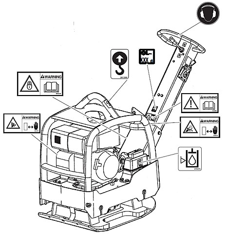
- Инструкция по эксплуатации для LF 50 9800 1117 13_L.pdf
- Инструкция по эксплуатации для LF 80 9800 1123 13_L.pdf
- Инструкция по эксплуатации для LF 60 9800 1119 13_L.pdf
- Инструкция по эксплуатации для LF 75 9800 1121 13_L.pdf
- Инструкция по эксплуатации для LF 80 9800 1123 13_L.pdf
- Инструкция по эксплуатации для LF 100 9800 1125 13_L.pdf
- Инструкция по эксплуатации для LF 130 9800 1127 13_L.pdf
- Инструкция по эксплуатации для LG 160 9800 1103 13_L.pdf
- Инструкция по эксплуатации для LG 200 9800 1105 13_L.pdf
- Инструкция по эксплуатации для LG 300 9800 1107 13_L.pdf
- Инструкция по эксплуатации для LG 400 9800 1109 13_L.pdf
- Инструкция по эксплуатации для LG 500 9800 1111 13_L.pdf
- Инструкция по эксплуатации для LH 700 9800 1113 13_L.pdf
- Инструкция по эксплуатации для LH 804 9800 1387 13_L.pdf
- Каталог запасных частей для LF 50 9800 1118 01_L.pdf
- Каталог запасных частей для LF 60 9800 1120 01_L.pdf
- Каталог запасных частей для LF 75 9800 1122 01_L.pdf
- Каталог запасных частей для LF 80 9800 1124 01_L.pdf
- Каталог запасных частей для LF 100 9800 1126 01_L.pdf
- Каталог запасных частей для LF 130 9800 1128 01_L.pdf
- Каталог запасных частей для LG 160 9800 1117 13_L.pdf
- Каталог запасных частей для LG 200 9800 1106 01_L.pdf
- Каталог запасных частей для LG 300 9800 1108 01_L.pdf
- Каталог запасных частей для LG 400 9800 1110 01_L.pdf
- Каталог запасных частей для LG 500 9800 1112 01_L.pdf
- Каталог запасных частей для LG 700 9800 1114 01_L.pdf
- Каталог запасных частей для LH 800 9800 1116 01_L.pdf
- Каталог запасных частей для LH 804 9800 1392 01_L.pdf
- Manuals
- Brands
- Atlas Copco Manuals
- Air Compressor
- GA90
- Instruction book
-
Contents
-
Table of Contents
-
Bookmarks
Quick Links
No. 2920 1475 00
Registration code:
³
Atlas Copco Stationary Air Compressors
GA90 — GA110 — GA132 — GA160 — GA200 — GA250 — GA315
GA90 W — GA110 W — GA132 W — GA160 W — GA200 W —
GA250 W — GA315 W
Instruction book
Important
·
·
AIF-078 300
AIF-078 302
®
Related Manuals for Atlas Copco GA90
Summary of Contents for Atlas Copco GA90
-
Page 1
Atlas Copco Stationary Air Compressors GA90 — GA110 — GA132 — GA160 — GA200 — GA250 — GA315 GA90 W — GA110 W — GA132 W — GA160 W — GA200 W — GA250 W — GA315 W Instruction book… -
Page 2: Table Of Contents
The company reserves the right to make changes without prior notice. Contents Leading particulars ……. . 3 4.1.1 Regular service operations .
-
Page 3: Leading Particulars
1 LEADING PARTICULARS 1.1 General description GA Full-feature (FF) ® 2920 1475 00…
-
Page 4
7 M25 51329F 2920 1475 00… -
Page 5: Main Options
1.1.1 Main options Oil containing frame Full-feature Modulating control Integrated DD filter Heavy-duty air intake filter Integrated OSD Rain protection Electronic drain High ambient temperature version Energy recovery Phase Sequence Relay 50837F 2920 1475 00…
-
Page 6
50852F 3 20 M26 4 50835F 8 7 9 2920 1475 00… -
Page 7: Air Flow / Regulating System
PT 1000 thermal protection 1.2.2 Condensate drain system Full-feature DIN/BSP or ANSI/NPT connections 1.2.3 Oil system 1) HD Roto-fluid Cooling air outlet ducting Lifting device 1.2.4 Cooling system On GA, GA W 1.2 Air flow / regulating system (Figs. 1.7 and 1.8) 1.2.5 Regulating system 1.2.1 Air flow 1)
-
Page 8
Fig. 1.7 GA90/160 Full-feature during unloading Air filter By-pass opening Air receiver Unloader Blow-off channel Oil separator element Unloading valve Chamber, receiver pressure Minimum pressure valve Air cooler Valve Check valve Cooling fan Shield Oil scavenging line Oil coolers Compressor element… -
Page 9
Oil drain plug Thermostatic expansion valve Refrigerant compressor By-pass valve Sight-glass Liquid separator Air outlet valve (customer’s Filter/dryer Low pressure switch installation) Capillary tube Air/refrigerant heat exchanger Condensate trap Fan control switch Air/air heat exchanger Channel High pressure switch By-pass valves Flexible, receiver pressure By-pass valve Insulating block… -
Page 10: Elektronikon
1.3.1 Automatic control of the compressor Warning A number of time-based automatic start/stop commands may be programmed. Take into Loading account that a start command will be executed (if programmed and activated), even after manually stopping the compressor. 1.3.2 Protecting the compressor Shut-down and motor overload 1.2.5.2 GA/GA W 200/315 Shut-down warning…
-
Page 11: Automatic Restart After Voltage Failure
1.4 Control panel 1.4.1 LEDs/buttons/keys Ref. Designation Function 1.3.4 Automatic restart after voltage failure Warning If activated and provided the module was in the automatic operation mode, the compressor will automatically restart if the supply voltage to the module is restored within a programmed time period.
-
Page 12: Display
1.4.2 Display Designation Function ¯ 1.4.4 Emergency stop button (S2-Fig. 1.9) 1.4.3 Function keys (5-Fig. 1.9) circuit to the control circuit and other electrical components is not broken. Warning Before starting any maintenance or repairs, wait until the compressor has stopped and open the isolating switch (customer’s installation) to switch off the voltage to the compressor.
-
Page 13
-Oil separator -Motor Starts -Dryer LAT -Module Hours -Emergency Stop -Load Relay -Remote Start/Stop Maximum Pressure 8.3 bar ↑ Automatic Operation -Compressor Outlet Compressor Outlet 6.4 bar -Remote Load/Unload -Dp oilseparator Local Control Running Hours 1016 hrs -Remote pressure sensing -Dp Air Filter ↓… -
Page 14: Main Screen
GA/GA W 200 up to 315 have two compressor elements, each provided with an unloader, check valve and oil stop valve. 2) GA90 and GA110 are provided with one fan. GA132 up to GA315 are provided with two fans. 2920 1475 00…
-
Page 15: Installation
2 INSTALLATION 2.1 Dimension drawings 2920 1475 00…
-
Page 16
2920 1475 00… -
Page 17
2920 1475 00… -
Page 18
2920 1475 00… -
Page 19
2920 1475 00… -
Page 20
2920 1475 00…