инструкцияGigabyte GA-78LMT-USB3 R2

GA-78LMT-USB3 R2
User’s Manual
Rev. 1001
To reduce the impacts on global warming, the packaging materials of this product
are recyclable and reusable. GIGABYTE works with you to protect the environment.
For more product details, please visit GIGABYTE’s website.
Посмотреть инструкция для Gigabyte GA-78LMT-USB3 R2 бесплатно. Руководство относится к категории Материнские платы, 2 человек(а) дали ему среднюю оценку 9.4. Руководство доступно на следующих языках: английский. У вас есть вопрос о Gigabyte GA-78LMT-USB3 R2 или вам нужна помощь? Задайте свой вопрос здесь
- GA-78LMT-USB3 R2 Motherboard Layout
- Chapter 1 Hardware Installation
- Chapter 2 BIOS Setup
- Chapter 3 Appendix
Главная
| Gigabyte | |
| GA-78LMT-USB3 R2 | GA-78LMT-USB3 R2 | |
| Материнская плата | |
| 4719331802578, 0889523012048 | |
| английский | |
| Руководство пользователя (PDF) |
Память
| Поддерживаемые типы памяти | DDR3-SDRAM |
| Тип слотов памяти | DIMM |
| Количество слотов памяти | 4 |
| Поддерживаемые частоты памяти | 1066,1333,1600 MHz |
| Максимальная внутренняя память | 32 GB |
Процессор
| Производитель процессора | AMD |
| Совместимые серии процессоров | AMD Phenom II x3 |
| Сокет процессора | Socket AM3+ |
Вес и размеры
| Ширина | 244 mm |
| Глубина | 244 mm |
Содержимое упаковки
| Поставляемое ПО | Norton® Internet Security |
BIOS
| Тип BIOS | AWARD |
| Версия ACPI | 1.0b |
| Перемычка Clear CMOS | Да |
Порты на задней панели
| Количество портов USB 2.0 | 4 |
| Количество портов USB 3.2 Gen 1 (3.1 Gen 1) Type-A | 2 |
| Количество портов USB 3.2 Gen 1 (3.1 Gen 1) Type-С | — |
| Количество портов USB 3.2 Gen 2 (3.1 Gen 2) Type-A | — |
| Количество портов USB 3.2 Gen 2 (3.1 Gen 2) Type-С | — |
| Количество портов Ethernet LAN ( RJ-45) | 1 |
| Количество портов eSATA | — |
| Количество портов PS/2 | 1 |
| Количество портов VGA (D-Sub) | 1 |
| Количество портов DVI-D | 1 |
| Количество HDMI портов | 1 |
| Порты FireWire | — |
Внутренние порты
| Разъем для вентилятора | Да |
| Разъем питания ATX (24-конт.) | Да |
| 12В разъем питания | Да |
| Число коннекторов SATA | 6 |
| Коннекторы последовательного порта | 1 |
| Количество разъемов SATA II | 2 |
| Количество разъемов SATA III | — |
| Количество параллельных разъемов ATA (PATA) | 1 |
| Разъем передней панели | Да |
| Аудиоразъем передней панели | Да |
| Разъемы USB 2.0 | 4 |
| Разъемы USB 3.2 Gen 1 (3.1 Gen 1) | 1 |
| Разъемы USB 3.2 Gen 2 (3.1 Gen 2) | — |
Прочие свойства
| параллельный порт через внутренний разъем | Да |
| S/PDIF коннектор входа | Да |
Слоты расширения
| Слоты PCI Express x16 (поколение 2.x) | 1 |
| Слоты PCI Express x1 (поколение 2.x) | 1 |
Свойства
| Южный мост материнской платы | AMD SB710 |
| Комплектующие для | ПК |
| Семейство чипсета материнской платы | AMD |
| Чипсет материнской платы | AMD 760G |
| Формат материнской платы | Mini ATX |
| Выходные звуковые каналы | 7.1 канала |
| Тип источника питания | ATX |
Контроллеры хранения данных
показать больше
Не можете найти ответ на свой вопрос в руководстве? Вы можете найти ответ на свой вопрос ниже, в разделе часто задаваемых вопросов о Gigabyte GA-78LMT-USB3 R2.
Какая ширина Gigabyte GA-78LMT-USB3 R2?
Какая толщина Gigabyte GA-78LMT-USB3 R2?
Инструкция Gigabyte GA-78LMT-USB3 R2 доступно в русский?
Не нашли свой вопрос? Задайте свой вопрос здесь
-
Драйверы
13
-
Инструкции по эксплуатации
1

Gigabyte GA-78LMT-USB3 R2 инструкция по эксплуатации
(35 страниц)
- Языки:Английский
-
Тип:
PDF -
Размер:
9.66 MB
Просмотр
На NoDevice можно скачать инструкцию по эксплуатации для Gigabyte GA-78LMT-USB3 R2. Руководство пользователя необходимо для ознакомления с правилами установки и эксплуатации Gigabyte GA-78LMT-USB3 R2. Инструкции по использованию помогут правильно настроить Gigabyte GA-78LMT-USB3 R2, исправить ошибки и выявить неполадки.
 Loading…
![]()
GA-78LMT-USB3
User’s Manual
Rev. 6003 12ME-78LTUB3-6003R
For more product details, please visit GIGABYTE’s website.
To reduce the impacts on global warming, the packaging materials of this product are recyclable and reusable. GIGABYTE works with you to protect the environment.

Motherboard
GA-78LMT-USB3
Motherboard
GA-78LMT-USB3
Oct. 6, 2014
Oct. 6, 2014
Copyright
© 2016 GIGA-BYTE TECHNOLOGY CO., LTD. All rights reserved.
The trademarks mentioned in this manual are legally registered to their respective owners.
Disclaimer
Information in this manual is protected by copyright laws and is the property of GIGABYTE.
ChangestothespecificationsandfeaturesinthismanualmaybemadebyGIGABYTEwithoutpriornotice.
No part of this manual may be reproduced, copied, translated, transmitted, or published in any form or by any means without GIGABYTE’s prior written permission.
In order to assist in the use of this product, carefully read the User’s Manual.
For product-related information, check on our website at: http://www.gigabyte.com
Identifying Your Motherboard Revision
The revision number on your motherboard looks like this: «REV: X.X.» For example, «REV: 1.0» means the revision of the motherboard is 1.0. Check your motherboard revision before updating motherboard BIOS,
drivers, or when looking for technical information. Example:

Table of Contents
|
GA-78LMT-USB3 Motherboard Layout…………………………………………………………………. |
4 |
|
|
GA-78LMT-USB3 Motherboard Block Diagram……………………………………………………… |
5 |
|
|
Chapter 1 Hardware Installation………………………………………………………………………….. |
6 |
|
|
1-1 |
Installation Precautions…………………………………………………………………………. |
6 |
|
1-2 |
Product Specifications………………………………………………………………………….. |
7 |
|
1-3 |
Installing the CPU………………………………………………………………………………… |
9 |
|
1-4 |
Installing the Memory……………………………………………………………………………. |
9 |
|
1-5 |
Installing an Expansion Card……………………………………………………………….. |
10 |
|
1-6 |
Back Panel Connectors………………………………………………………………………. |
10 |
|
1-7 |
Internal Connectors……………………………………………………………………………. |
12 |
|
Chapter 2 BIOS Setup……………………………………………………………………………………… |
17 |
|
|
2-1 |
Startup Screen…………………………………………………………………………………… |
18 |
|
2-2 |
MB Intelligent Tweaker(M.I.T.)……………………………………………………………… |
19 |
|
2-3 |
Standard CMOS Features…………………………………………………………………… |
22 |
|
2-4 |
Advanced BIOS Features……………………………………………………………………. |
23 |
|
2-5 |
Integrated Peripherals………………………………………………………………………… |
25 |
|
2-6 |
Power Management Setup………………………………………………………………….. |
27 |
|
2-7 |
PnP/PCI Configurations………………………………………………………………………. |
28 |
|
2-8 |
PC Health Status……………………………………………………………………………….. |
29 |
|
2-9 |
Load Fail-Safe Defaults………………………………………………………………………. |
30 |
|
2-10 |
Load Optimized Defaults…………………………………………………………………….. |
30 |
|
2-11 |
Set Supervisor/User Password…………………………………………………………….. |
30 |
|
2-12 |
Save & Exit Setup………………………………………………………………………………. |
30 |
|
2-13 |
Exit Without Saving…………………………………………………………………………….. |
30 |
|
Chapter 3 Appendix…………………………………………………………………………………………. |
31 |
|
|
3-1 |
Drivers Installation……………………………………………………………………………… |
31 |
|
3-2 |
Configuring SATA Hard Drive(s)…………………………………………………………… |
31 |
|
Regulatory Statements…………………………………………………………………………………. |
33 |
|
|
Contact Us………………………………………………………………………………………………….. |
36 |
— 3 —
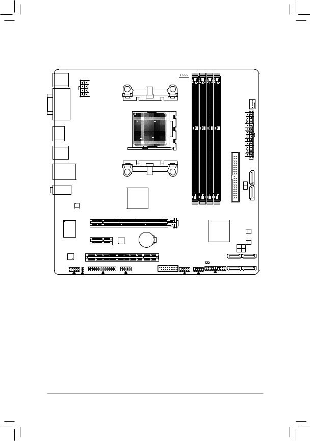
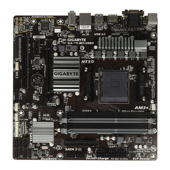
GA-78LMT-USB3 Motherboard Layout
|
KB_MS_USB |
||
|
DVI VGA |
ATX_12V |
|
|
HDMI |
USB3 |
|
|
R_USB30 |
||
|
78LMT- |
||
|
USB_LAN |
||
|
AUDIO |
GA- |
|
|
Realtek® |
||
|
GbE LAN |
||
|
PCIEX16 |
||
|
SuperiTE® I/O |
PCIEX1 |
|
|
CODEC |
PCI |
CPU_FAN 


SYS_FAN
AM3+
ATX
|
IDE |
|||
|
SATA2 |
|||
|
5 |
|||
|
4 |
|||
|
AMD 760G |
|||
|
DDR3 4 |
DDR3 2 DDR3 3 DDR3 1 |
||
|
VIA® |
AMD SB710 |
B_BIOS |
|
|
VL805 |
M_BIOS |
||
|
BAT |
|||
|
SATA2 |
2 |
3 |
|
|
0 |
1 |
||
|
F_USB30 |
CLR_CMOS |
||
|
F_AUDIO SPDIF_O LPT |
COM |
F_USB2 F_USB1 F_PANEL |
Box Contents
|
55 |
GA-78LMT-USB3 motherboard |
||
|
55 |
Motherboard driver disk |
55 |
Two SATA cables |
|
55 |
User’s Manual |
55 |
One IDE cable |
|
55 |
I/O Shield |
*The box contents above are for reference only and the actual items shall depend on the product package you obtain. The box contents are subject to change without notice.
—4 —
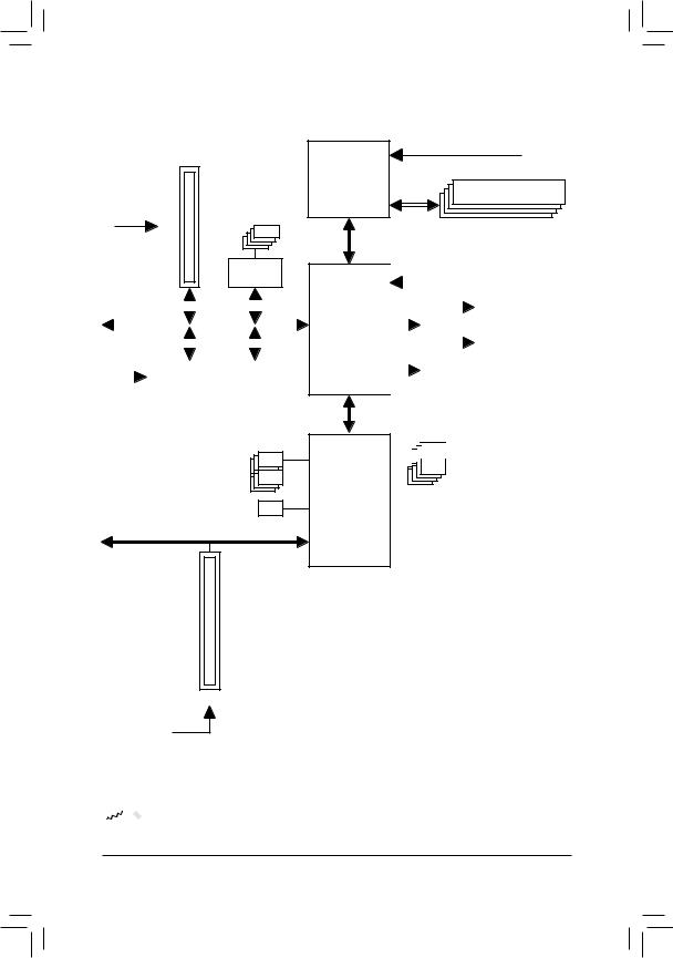
GA-78LMT-USB3 Motherboard Block Diagram
1 PCI Express x16
4 USB 3.0/2.0
PCIe CLK
(100 MHz)
VIA®
VL805
|
x16 |
x1 |
||||||||||||||
|
PCI Express Bus |
x1 |
x1 |
|||||||||||||
|
Realtek® |
|||||||||||||||
|
GbE LAN |
|||||||||||||||
|
PCIe CLK |
|||||||||||||||
|
(100 MHz) |
RJ45 |
||||||||||||||
|
1 PCI Express x1 |
|||||||||||||||
|
LAN |
6 SATA 3Gb/s
ATA-133/100/66/33
IDE Channel
PCI Bus
CPU CLK+/- (200 MHz)
AM3+/AM3 CPU DDR3 1333+ (O.C.)/1066 MHz
Dual Channel Memory
Hyper Transport 3.0
|
GFX CLK (100 MHz) |
|||||||||
|
Switch |
HDMI |
||||||||
|
AMD 760G |
or |
||||||||
|
DVI-D |
|||||||||
|
D-Sub |
|||||||||


 8 USB 2.0/1.1
|
AMD SB710 |
||||||||||||||
|
Dual BIOS |
||||||||||||||
|
LPC |
||||||||||||||
|
LPT |
||||||||||||||
|
Bus |
iTE® |
|||||||||||||
|
Super I/O |
COM |
|||||||||||||
|
CODEC |
||||||||||||||
|
PS/2 KB/Mouse |
||||||||||||||
|
(Center/Subwoofer |
(Front |
S/PDIFOut |
|
Out)Speaker |
Out)Speaker Out)Speaker |
|
|
MIC |
(Rear |
|
|
Line |
||
|
In |
||
|
Out |
||
|
Line |

 For detailed product information/limitation(s), refer to «1-2 Product Specifications.»
— 5 —

Chapter 1 Hardware Installation
1-1 Installation Precautions
The motherboard contains numerous delicate electronic circuits and components which can become damaged as a result of electrostatic discharge (ESD). Prior to installation, carefully read the user’s manual and follow these procedures:
•• Prior to installation, make sure the chassis is suitable for the motherboard.
•• Prior to installation, do not remove or break motherboard S/N (Serial Number) sticker or warranty sticker provided by your dealer. These stickers are required for warranty validation.
•• Always remove the AC power by unplugging the power cord from the power outlet before installing or removing the motherboard or other hardware components.
•• When connecting hardware components to the internal connectors on the motherboard, make sure they are connected tightly and securely.
•• When handling the motherboard, avoid touching any metal leads or connectors.
•• It is best to wear an electrostatic discharge (ESD) wrist strap when handling electronic components such as a motherboard, CPU or memory. If you do not have an ESD wrist strap, keep your hands dry and first touch a metal object to eliminate static electricity.
•• Prior to installing the motherboard, please have it on top of an antistatic pad or within an electrostatic shielding container.
•• Before connecting or unplugging the power supply cable from the motherboard, make sure the power supply has been turned off.
•• Before turning on the power, make sure the power supply voltage has been set according to the local voltage standard.
•• Before using the product, please verify that all cables and power connectors of your hardware components are connected.
•• To prevent damage to the motherboard, do not allow screws to come in contact with the motherboard circuit or its components.
•• Make sure there are no leftover screws or metal components placed on the motherboard or within the computer casing.
•• Do not place the computer system on an uneven surface.
•• Do not place the computer system in a high-temperature or wet environment.
•• Turning on the computer power during the installation process can lead to damage to system components as well as physical harm to the user.
•• If you are uncertain about any installation steps or have a problem related to the use of the product, please consult a certified computer technician.
•• If you use an adapter, extension power cable, or power strip, ensure to consult with its installation and/or grounding instructions.
— 6 —
|
1-2 |
Product Specifications |
||
|
CPU |
AM3+ Socket: |
||
|
— AMD AM3+ processor |
|||
|
— AMD AM3 Phenom™ II processor/ AMD Athlon™ II processor |
|||
|
(Go to GIGABYTE’s website for the latest CPU support list.) |
|||
|
HyperTransport |
HyperTransport™ 3.0 |
||
|
Bus |
Support for up to 5200 MT/s |
||
|
Chipset |
North Bridge: AMD 760G |
||
|
South Bridge: AMD SB710 |
|||
|
Memory |
4 x DDR3 DIMM sockets supporting up to 32 GB of system memory |
||
|
* Due to a Windows 32-bit operating system limitation, when more than 4 GB of physical |
|||
|
memory is installed, the actual memory size displayed will be less than the size of |
|||
|
the physical memory installed. |
|||
|
Dual channel memory architecture |
|||
|
Support for DDR3 1333+ (O.C.)/1066 MHz memory modules |
|||
|
(Go to GIGABYTE’s website for the latest supported memory speeds and memory |
|||
|
modules.) |
|||
|
Onboard |
North Bridge: |
||
|
Graphics |
— 1 x D-Sub port, supporting a maximum resolution of 1920×1200 |
||
|
— 1 x DVI-D port, supporting a maximum resolution of 1920×1200 |
|||
|
* The DVI-D port does not support D-Sub connection by adapter. |
|||
|
— 1 x HDMI port, supporting a maximum resolution of 1920×1200 |
|||
|
* Simultaneous output for DVI-D and HDMI is not supported. |
|||
|
— Support for DirectX 10 |
|||
|
Audio |
Realtek® ALC892 codec |
||
|
High Definition Audio |
|||
|
2/4/5.1/7.1-channel |
*To configure 7.1-channel audio, you have to use an HD front panel audio module and enable the multi-channel audio feature through the audio driver.
Support for S/PDIF Out
|
LAN |
Realtek® GbE LAN chip (10/100/1000 Mbit) |
|||
|
Expansion Slots |
1 x PCI Express x16 slot, running at x16 |
|||
|
1 x PCI Express x1 slot |
||||
|
(All PCI Express slots conform to PCI Express 2.0 standard.) |
||||
|
1 x PCI slot |
||||
|
Storage Interface |
South Bridge: |
|||
|
— |
1 x IDE connector supporting ATA-133/100/66/33 |
|||
|
— |
6 x SATA 3Gb/s connectors |
|||
|
— |
Support for RAID 0, RAID 1, RAID 10, and JBOD |
|||
|
USB |
Chipset: |
|||
|
— |
8 USB 2.0/1.1 ports (4 ports on the back panel, 4 ports available through the |
|||
|
internal USB headers) |
||||
|
VIA® VL805 chip: |
||||
|
— |
4 USB 3.0/2.0 ports (2 ports on the back panel, 2 ports available through the |
|||
|
internal USB header) |
||||
|
Internal |
1 x 24-pin ATX main power connector |
|||
|
Connectors |
1 x 8-pin ATX 12V power connector |
|||
|
6 x SATA 3Gb/s connectors |
||||
|
1 x IDE connector |
||||
|
1 x CPU fan header |
||||
|
1 x system fan header |
||||
|
— 7 — |

|
Internal |
1 x front panel header |
||
|
Connectors |
1 x front panel audio header |
||
|
1 x S/PDIF Out header |
|||
|
1 x USB 3.0/2.0 header |
|||
|
2 x USB 2.0/1.1 headers |
|||
|
1 x serial port header |
|||
|
1 x parallel port header |
|||
|
1 x Clear CMOS jumper |
|||
|
Back Panel |
1 x PS/2 keyboard/mouse port |
||
|
Connectors |
1 x D-Sub port |
||
|
1 x DVI-D port |
|||
|
1 x HDMI port |
|||
|
2 x USB 3.0/2.0 ports |
|||
|
4 x USB 2.0/1.1 ports |
|||
|
1 x RJ-45 port |
|||
|
3 x audio jacks (Line In, Line Out, Microphone) |
|||
|
I/O Controller |
iTE® I/O Controller Chip |
||
|
Hardware |
System voltage detection |
||
|
Monitor |
CPU/System temperature detection |
||
|
CPU/System fan speed detection |
|||
|
CPU overheating warning |
|||
|
CPU/System fan fail warning |
|||
|
CPU/System fan speed control |
|||
|
* Whether the fan speed control function is supported will depend on the cooler you |
|||
|
install. |
|||
|
BIOS |
2 x 32 Mbit flash |
||
|
Use of licensed AWARD BIOS |
|||
|
Support for DualBIOS™ |
|||
|
PnP 1.0a, DMI 2.0, SM BIOS 2.4, ACPI 1.0b |
|||
|
Unique Features |
Support for @BIOS |
||
|
Support for Q-Flash |
|||
|
Support for Xpress BIOS Rescue |
|||
|
Support for Download Center |
|||
|
Support for Xpress Install |
|||
|
Support for EasyTune |
|||
|
* Available functions in EasyTune may differ by motherboard model. |
|||
|
Support for Smart Recovery2 |
|||
|
Support for Auto Green |
|||
|
Support for ON/OFF Charge |
|||
|
Support for Q-Share |
|||
|
Bundled |
Norton® Internet Security (OEM version) |
||
|
Software |
|||
|
Operating |
Support for Windows 7/XP |
||
|
System |
|||
|
Form Factor |
Micro ATX Form Factor; 24.4cm x 24.4cm |
*GIGABYTE reserves the right to make any changes to the product specifications and product-related information without prior notice.
*Please visit the Support & DownloadsUtility page on GIGABYTE’s website to check the supported operating system(s) for the software listed in the «Unique Features» and «Bundled Software» columns.
—8 —
|
1-3 |
Installing the CPU |
|
|
Read the following guidelines before you begin to install the CPU: |
||
|
•• |
Make sure that the motherboard supports the CPU. |
|
|
•• |
(Go to GIGABYTE’s website for the latest CPU support list.) |
|
|
Always turn off the computer and unplug the power cord from the power outlet before installing the |
||
|
CPU to prevent hardware damage. |
||
|
•• |
Locate the pin one of the CPU. The CPU cannot be inserted if oriented incorrectly. |
|
|
•• |
Apply an even and thin layer of thermal grease on the surface of the CPU. |
|
|
•• |
Do not turn on the computer if the CPU cooler is not installed, otherwise overheating and damage |
|
|
of the CPU may occur. |
||
|
•• |
Set the CPU host frequency in accordance with the CPU specifications. It is not recommended |
|
|
that the system bus frequency be set beyond hardware specifications since it does not meet the |
||
|
standard requirements for the peripherals. If you wish to set the frequency beyond the standard |
||
|
specifications, please do so according to your hardware specifications including the CPU, graphics |
||
|
card, memory, hard drive, etc. |
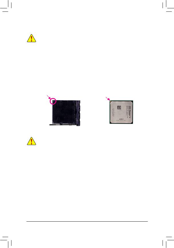
Installing the CPU
Locate the pin one (denoted by a small triangle) of the CPU socket and the CPU.
|
A Small Triangle |
A Small Triangle |
|||
|
Marking Denotes Pin |
AM3+ Socket |
AM3+/AM3 CPU |
||
|
Marking Denotes CPU |
||||
|
One of the Socket |
||||
|
Pin One |
||||
1-4 Installing the Memory
Read the following guidelines before you begin to install the memory:
•• Make sure that the motherboard supports the memory. It is recommended that memory of the same capacity, brand, speed, and chips be used.
(Go to GIGABYTE’s website for the latest supported memory speeds and memory modules.)
•• Always turn off the computer and unplug the power cord from the power outlet before installing the memory to prevent hardware damage.
•• Memory modules have a foolproof design. A memory module can be installed in only one direction. If you are unable to insert the memory, switch the direction.
Dual Channel Memory Configuration
This motherboard provides four DDR3 memory sockets and supports Dual Channel Technology. After the memory is installed, the BIOS will automatically detect the specifications and capacity of the memory. Enabling
Dual Channel memory mode will double the original memory bandwidth.
The four DDR3 memory sockets are divided into two channels and each channel has two memory sockets as following:
Channel 0: DDR3_2, DDR3_4Channel 1: DDR3_1, DDR3_3
Dual Channel Memory Configurations Table
|
DDR3_4 |
DDR3_2 |
DDR3_3 |
DDR3_1 |
|
|
Two Modules |
— — |
DS/SS |
— — |
DS/SS |
|
DS/SS |
— — |
DS/SS |
— — |
|
|
4 Modules |
DS/SS |
DS/SS |
DS/SS |
DS/SS |
(SS=Single-Sided, DS=Double-Sided, «- -«=No Memory)
— 9 —
Due to CPU limitations, read the following guidelines before installing the memory in Dual Channel mode.
1.Dual Channel mode cannot be enabled if only one DDR3 memory module is installed.
2.When enabling Dual Channel mode with two or four memory modules, it is recommended that memory of the same capacity, brand, speed, and chips be used and installed in the same colored DDR3 sockets for optimum performance.
1-5 Installing an Expansion Card
Read the following guidelines before you begin to install an expansion card:
•• Make sure the motherboard supports the expansion card. Carefully read the manual that came with your expansion card.
•• Always turn off the computer and unplug the power cord from the power outlet before installing an expansion card to prevent hardware damage.
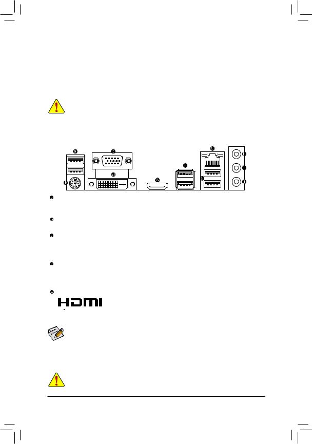
1-6 Back Panel Connectors
USB 2.0/1.1 Port
The USB port supports the USB 2.0/1.1 specification. Use this port for USB devices such as a USB keyboard/mouse, USB printer, USB flash drive and etc.
PS/2 Keyboard/Mouse Port
Use this port to connect a PS/2 mouse or keyboard.
D-Sub Port
The D-Sub port supports a 15-pin D-Sub connector and supports a maximum resolution of 1920×1200 (the actual resolutions supported depend on the monitor being used). Connect a monitor that supports D-Sub connection to this port.
DVI-D Port (Note 1)
The DVI-D port conforms to the DVI-D specification and supports a maximum resolution of 1920×1200
(the actual resolutions supported depend on the monitor being used). Connect a monitor that supports DVI-D connection to this port.
HDMI Port (Note 2)
 The HDMI (High-Definition Multimedia Interface) provides an all-digital audio/


 video interface to transmit the uncompressed audio/video signals and is HDCP compliant. Connect the HDMI audio/video device to this port. The HDMI Technology can support a maximum resolution of 1920×1200 but the actual resolutions supported depend on the monitor being used.
•• After installing the HDMI device, make sure to set the default sound playback device to HDMI. (The item name may differ depending on your operating system.)
•• Please note the HDMI audio output only supports AC3, DTS and 2-channel-LPCM formats. (AC3 and DTS require the use of an external decoder for decoding.)
(Note 1) The DVI-D port does not support D-Sub connection by adapter. (Note 2) Simultaneous output for DVI-D and HDMI is not supported.
•• When removing the cable connected to a back panel connector, first remove the cable from your device and then remove it from the motherboard.
•• When removing the cable, pull it straight out from the connector. Do not rock it side to side to prevent an electrical short inside the cable connector.
— 10 —
![]()
A. Dual Display Configurations:
This motherboard provides three video output ports. The table below shows the supported dual display configurations.
|
Dual Display |
Combination |
Supported or Not |
|
D-Sub + DVI-D |
Yes |
|
|
D-Sub + HDMI |
Yes |
|
|
DVI-D + HDMI |
No |
B. Playback of Blu-ray™ Discs:
In order to get better playback quality, when playing the Blu-ray™ discs, refer to the recommended system requirements (or better) below.
•• Memory: Two 1 GB DDR3 1066 MHz memory modules with dual channel mode enabled
•• BIOS Setup: At least 256 MB of UMA Frame Buffer Size (refer to Chapter 2, «BIOS Setup,» «Advanced BIOS Features,» for more information)
•• Playback software: CyberLink PowerDVD 10.0 or later (Note: Please ensure Hardware Acceleration is enabled.)
•• HDCP compliant monitor(s)
USB 3.0/2.0 Port
The USB 3.0 port supports the USB 3.0 specification and is compatible to the USB 2.0/1.1 specification.
Use this port for USB devices Use this port for USB devices such as a USB keyboard/mouse, USB printer,
USB flash drive and etc.
RJ-45 LAN Port
The Gigabit Ethernet LAN port provides Internet connection at up to 1 Gbps data rate. The following describes the states of the LAN port LEDs.
|
Connection/ |
Connection/Speed LED: |
Activity LED: |
|||||||||||||||||
|
Speed LED |
Activity LED |
||||||||||||||||||
|
State |
Description |
State |
Description |
||||||||||||||||
|
Orange |
1 Gbps data rate |
Blinking |
Data transmission or receiving is occurring |
||||||||||||||||
|
Green |
100 Mbps data rate |
Off |
No data transmission or receiving is occurring |
||||||||||||||||
|
Off |
10 Mbps data rate |
||||||||||||||||||
|
LAN Port |
|||||||||||||||||||
Line In Jack (Blue)
The line in jack. Use this audio jack for line in devices such as an optical drive, walkman, etc.
Line Out Jack (Green)
The line out jack. Use this audio jack for a headphone or 2-channel speaker. This jack can be used to connect front speakers in a 4/5.1/7.1-channel audio configuration.
Mic In Jack (Pink)
The Mic in jack. Microphones must be connected to this jack.
To configure 7.1-channel audio, you have to use an HD front panel audio module and enable the multi-channel audio feature through the audio driver.
— 11 —
- Manuals
- Brands
- Gigabyte Manuals
- Motherboard
- GA-78LMT-USB3
- User manual
Manual
-
Contents
-
Table of Contents
-
Bookmarks
Quick Links
GA-78LMT-USB3
User’s Manual
Rev. 4101
12ME-78LTUB3-4101R
Related Manuals for Gigabyte GA-78LMT-USB3
Summary of Contents for Gigabyte GA-78LMT-USB3
-
Page 1
GA-78LMT-USB3 User’s Manual Rev. 4101 12ME-78LTUB3-4101R… -
Page 3: Identifying Motherboard Revision
The trademarks mentioned in this manual are legally registered to their respective owners. Disclaimer Information in this manual is protected by copyright laws and is the property of GIGABYTE. Changes to the specifications and features in this manual may be made by GIGABYTE without prior notice.
-
Page 4: Table Of Contents
Table of Contents GA-78LMT-USB3 Motherboard Layout …………….5 GA-78LMT-USB3 Motherboard Block Diagram …………..6 Chapter 1 Hardware Installation ………………7 Installation Precautions ………………. 7 1-2 Product Specifications ………………8 Installing the CPU ………………10 Installing the Memory ………………11 Installing an Expansion Card …………….11 Back Panel Connectors …………….. 12 Internal Connectors ………………
-
Page 5: Ga-78Lmt-Usb3 Motherboard Layout
GA-78LMT-USB3 Motherboard Layout CPU_FAN KB_MS_USB SYS_FAN ATX_12V AM3+ R_USB30 SATA2 Etron USB_LAN EJ168 AUDIO AMD 760G Realtek GbE LAN PCIEX16 B_BIOS AMD SB710 GA-78LMT-USB3 PCIEX1 M_BIOS Etron SATA2 CODEC EJ168 CLR_CMOS F_USB30 F_AUDIO SPDIF_O F_USB2 F_USB1 F_PANEL Box Contents 5 GA-78LMT-USB3 motherboard…
-
Page 6: Ga-78Lmt-Usb3 Motherboard Block Diagram
GA-78LMT-USB3 Motherboard Block Diagram CPU CLK+/- (200 MHz) 1 PCI Express x16 DDR3 1333+ (O.C.)/1066 MHz AM3+/AM3 CPU Dual Channel Memory 2 USB 3.0/2.0 2 USB 3.0/2.0 Hyper Transport 3.0 PCIe CLK (100 MHz) Etron Etron GFX CLK (100 MHz)
-
Page 7: Chapter 1 Hardware Installation
Chapter 1 Hardware Installation Installation Precautions The motherboard contains numerous delicate electronic circuits and components which can become damaged as a result of electrostatic discharge (ESD). Prior to installation, carefully read the user’s manual and follow these procedures: • Prior to installation, make sure the chassis is suitable for the motherboard. •…
-
Page 8: Product Specifications
Dual channel memory architecture Š Support for DDR3 1333+ (O.C.)/1066 MHz memory modules Š (Go to GIGABYTE’s website for the latest supported memory speeds and memory modules.) Onboard North Bridge: Š 1 x D-Sub port…
-
Page 9
Internal 1 x 24-pin ATX main power connector Š Connectors 1 x 8-pin ATX 12V power connector Š 6 x SATA 3Gb/s connectors Š 1 x IDE connector Š 1 x CPU fan header Š 1 x system fan header Š… -
Page 10: Installing The Cpu
* GIGABYTE reserves the right to make any changes to the product specifications and product-related information without prior notice. * Please visit GIGABYTE’s website to check the supported operating system(s) for the software listed in the «Unique Features» and «Bundled Software» columns.
-
Page 11: Installing The Memory
• Make sure that the motherboard supports the memory. It is recommended that memory of the same capacity, brand, speed, and chips be used. (Go to GIGABYTE’s website for the latest supported memory speeds and memory modules.) • Always turn off the computer and unplug the power cord from the power outlet before installing the memory to prevent hardware damage.
-
Page 12: Back Panel Connectors
Back Panel Connectors USB 2.0/1.1 Port The USB port supports the USB 2.0/1.1 specification. Use this port for USB devices such as a USB keyboard/mouse, USB printer, USB flash drive and etc. PS/2 Keyboard/Mouse Port Use this port to connect a PS/2 mouse or keyboard. D-Sub Port The D-Sub port supports a 15-pin D-Sub connector.
-
Page 13
A. Dual Display Configurations: This motherboard provides three video output ports: DVI-D, HDMI, and HDMI. The table below shows the supported dual display configurations. Dual Display Combination Supported or Not D-Sub + DVI-D D-Sub + HDMI DVI-D + HDMI B. Playback of Blu-ray Discs: In order to get better playback quality, when playing the Blu-ray discs, refer to the recommended system requirements (or better) below. -
Page 14: Internal Connectors
Internal Connectors ATX_12V F_AUDIO SPDIF_O CPU_FAN F_USB30 SYS_FAN F_USB1/F_USB2 SATA2 0/1/2/3/4/5 CLR_CMOS F_PANEL Read the following guidelines before connecting external devices: • First make sure your devices are compliant with the connectors you wish to connect. • Before installing the devices, be sure to turn off the devices and your computer. Unplug the power cord from the power outlet to prevent damage to the devices.
-
Page 15
1/2) ATX_12V_2X4/ATX (2×4 12V Power Connector and 2×12 Main Power Connector) With the use of the power connector, the power supply can supply enough stable power to all the components on the motherboard. Before connecting the power connector, first make sure the power supply is turned off and all devices are properly installed. The power connector possesses a foolproof design. Connect the power supply cable to the power connector in the correct orientation. -
Page 16
3/4) CPU_FAN/SYS_FAN (Fan Headers) All fan headers on this motherboard are 4-pin. Most fan headers possess a foolproof insertion design. When connecting a fan cable, be sure to connect it in the correct orientation (the black connector wire is the ground wire). The speed control function requires the use of a fan with fan speed control design. For optimum heat dissipation, it is recommended that a system fan be installed inside the chassis. -
Page 17
6) IDE (IDE Connector) The IDE connector supports up to two IDE devices such as hard drives and optical drives. Before attaching the IDE cable, locate the foolproof groove on the connector. If you wish to connect two IDE devices, remember to set the jumpers and the cabling according to the role of the IDE devices (for example, master or slave). -
Page 18: Front Panel Header
 F_PANEL (Front Panel Header) Connect the power switch, reset switch, speaker, chassis intrusion switch/sensor and system status indicator on the chassis to this header according to the pin assignments below. Note the positive and negative pins before connecting the cables. Message/Power/ Power Sleep LED…
 -
Page 19
9) F_AUDIO (Front Panel Audio Header) The front panel audio header supports Intel High Definition audio (HD) and AC’97 audio. You may connect your chassis front panel audio module to this header. Make sure the wire assignments of the module connector match the pin assignments of the motherboard header. Incorrect connection between the module connector and the motherboard header will make the device unable to work or even damage it. For HD Front Panel Audio: For AC’97 Front Panel Audio: Pin No. -
Page 20
11) F_USB30 (USB 3.0/2.0 Header) The header conforms to USB 3.0/2.0 specification and can provide two USB ports. For purchasing the optional 3.5″ front panel that provides two USB 3.0/2.0 ports, please contact the local dealer. F_USB30 F_AUDIO(H) Pin No. Definition Pin No. Definition VBUS SSRX1- SSRX1+ SSTX2+ SSTX1- SSTX2- SSTX1+ BIOS SSRX2+ DB_PORT SSRX2- VBUS No Pin Voltage measurement module(X58A-OC) -
Page 21
13) COM (Serial Port Header) The COM header can provide one serial port via an optional COM port cable. For purchasing the optional COM port cable, please contact the local dealer. Pin No. Definition NDCD- NSIN NSOUT NDTR- NDSR- NRTS- NCTS- NRI- No Pin… -
Page 22: Clear Cmos Jumper
15) CLR_CMOS (Clear CMOS Jumper) Use this jumper to clear the CMOS values (e.g. date information and BIOS configurations) and reset the CMOS values to factory defaults. To clear the CMOS values, use a metal object like a screwdriver to touch the two pins for a few seconds. Open: Normal Short: Clear CMOS Values • Always turn off your computer and unplug the power cord from the power outlet before clearing the CMOS values.
-
Page 23: Chapter 2 Bios Setup
To access the BIOS Setup program, press the <Delete> key during the POST when the power is turned on. To upgrade the BIOS, use either the GIGABYTE Q-Flash or @BIOS utility. Q-Flash allows the user to quickly and easily upgrade or back up BIOS without entering the operating system.
-
Page 24: The Main Menu
The Main Menu Once you enter the BIOS Setup program, the Main Menu (as shown below) appears on the screen. Use arrow keys to move among the items and press <Enter> to accept or enter a sub-menu. (Sample BIOS Version: D1) CMOS Setup Utility-Copyright (C) 1984-2012 Award Software ` MB Intelligent Tweaker(M.I.T.) Load Fail-Safe Defaults ` Standard CMOS Features…
-
Page 25: Mb Intelligent Tweaker(M.i.t.)
MB Intelligent Tweaker(M.I.T.) CMOS Setup Utility-Copyright (C) 1984-2012 Award Software MB Intelligent Tweaker(M.I.T.) Item Help ` IGX Configuration [Press Enter] Menu Level ` CPU Clock Ratio [Auto] 2800Mhz CPU NorthBridge Freq. [Auto] 2000Mhz Core Performance Boost (Note) [Enabled] (Note) CPB Ratio [Auto] 3100Mhz Turbo CPB…
-
Page 26: Cpu Clock Ratio
& Surround View Enables or disables the Surround View function. This option is configurable only when Init Display First under Advanced BIOS Features is set to PEG and an ATI graphics card is installed. (Default: Disabled) & Onboard VGA output connect Specifies the graphics display of the onboard graphics output from the D-SUB/DVI-D or D-SUB/HDMI. BIOS automatically determines the primary display port for output, depending on to Auto which port the display device is connected, D-SUB/DVI-D or D-SUB/HDMI.
-
Page 27: Memory Clock
& HT Link Frequency Allows you to manually set the frequency for the HT Link between the CPU and chipset. BIOS will automatically adjust the HT Link Frequency. (Default) Auto Sets HT Link Frequency to x1~x10 (200 MHz~2.0 GHz). x1~x10 &…
-
Page 28
& TwTr Command Delay Options are: Auto (default), 4T~7T. & Trfc0 for DIMM1, DIMM3 Options are: Auto (default), 90ns, 110ns, 160ns, 300ns, 350ns. & Trfc1 for DIMM2, DIMM4 Options are: Auto (default), 90ns, 110ns, 160ns, 300ns, 350ns. & Write Recovery Time Options are: Auto (default), 5T~8T, 10T, 12T. -
Page 29: Standard Cmos Features
& CPU NB VID Control Allows you to set the CPU North Bridge VID voltage. Auto sets the CPU North Bridge VID voltage as required. The adjustable range is dependent on the CPU being installed. (Default: Normal) Note: Increasing CPU voltage may result in damage to your CPU or reduce the useful life of the CPU. &…
-
Page 30: Advanced Bios Features
Access Mode Sets the hard drive access mode. Options are: Auto (default), Large. Approximate capacity of the currently installed hard drive. Capacity & Halt On Allows you to determine whether the system will stop for an error during the POST. Options are: «All Errors,»…
-
Page 31: Cpu Core
& AMD K8 Cool&Quiet control Lets the AMD Cool’n’Quiet driver dynamically adjust the CPU clock and VID to reduce Auto heat output from your computer and its power consumption. (Default) Disables this function. Disabled & CPU Unlock (Note) Allows you to determine whether unlock hidden CPU cores. (Default: Disabled) &…
-
Page 32: Integrated Peripherals
& Full Screen LOGO Show Allows you to determine whether to display the GIGABYTE Logo at system startup. Disabled displays normal POST message. (Default: Enabled) & Init Display First Specifies the first initiation of the monitor display from the installed PCI graphics card, PCI Express graphics card, or the onboard graphics. PCI Slot Sets the PCI graphics card as the first display. (Default) Sets the onboard graphics as the first display. OnChipVGA PEG Sets the PCI Express graphics card on the PCIEX16 slot as the first display.
-
Page 33: Onboard Audio Function
& OnChip SATA Port as ESP CMOS Setup Utility-Copyright (C) 1984-2012 Award Software OnChip SATA Port as ESP Item Help Port0 as ESP [Disabled] Menu Level « Port1 as ESP [Disabled] Port2 as ESP [Disabled] Port3 as ESP [Disabled] x Port4 as ESP Disabled x Port5 as ESP Disabled…
-
Page 34: Power Management Setup
& R_USB30 Controller (Etron EJ168 USB Controller, USB 3.0/2.0 ports on the back panel) Enables or disables the Etron EJ168 USB controller. (Default: Enabled) & USB Controllers Enables or disables the integrated USB controller. (Default: Enabled) Disabled will turn off all of the USB functionalities below. &…
-
Page 35: Acpi Suspend Type
& ACPI Suspend Type Specifies the ACPI sleep state when the system enters suspend. Enables the system to enter the ACPI S1 (Power on Suspend) sleep state. In S1 sleep S1(POS) state, the system appears suspended and stays in a low power mode. The system can be resumed at any time. Enables the system to enter the ACPI S3 (Suspend to RAM) sleep state (default).
-
Page 36: Pnp/Pci Configurations
& AC Back Function Determines the state of the system after the return of power from an AC power loss. T he system stays off upon the return of the AC power. (Default) Soft-Off The system is turned on upon the return of the AC power. Full-On The system returns to its last known awake state upon the return of the AC power. Memory & Power-On by Alarm Determines whether to power on the system at a desired time. (Default: Disabled) If enabled, set the date and time as following: Date (of Month) Alarm: Turn on the system at a specific time on each day or on a specific day in a month. Resume Time (hh: mm: ss): Set the time at which the system will be powered on automatically. Note: When using this function, avoid inadequate shutdown from the operating system or removal of the AC power, or the settings may not be effective. & ErP Support Determines whether to let the system consume least power in S5 (shutdown) state. (Default: Disabled) Note: When this item is set to Enabled, the following four functions will become unavailable: PME event wake up, power on by mouse, power on by keyboard, and wake on LAN. 2-8 PnP/PCI Configurations CMOS Setup Utility-Copyright (C) 1984-2012 Award Software PnP/PCI Configurations Item Help PCI1 IRQ Assignment [Auto] Menu Level …
-
Page 37: Load Fail-Safe Defaults
& Hardware Thermal Control Enables or disables the CPU overheating protection function. When enabled, the CPU core voltage and ratio will be reduced when the CPU is overheated. (Default: Enabled) & Reset Case Open Status Keeps or clears the record of previous chassis intrusion status. (Default) Disabled Clears the record of previous chassis intrusion status and the Case Opened field will Enabled…
-
Page 38: Load Optimized Defaults
2-11 Load Optimized Defaults CMOS Setup Utility-Copyright (C) 1984-2012 Award Software ` MB Intelligent Tweaker(M.I.T.) Load Fail-Safe Defaults ` Standard CMOS Features Load Optimized Defaults ` Advanced BIOS Features Set Supervisor Password ` Integrated Peripherals Set User Password ` Power Management Setup Save &…
-
Page 39: Save & Exit Setup
2-13 Save & Exit Setup CMOS Setup Utility-Copyright (C) 1984-2012 Award Software ` MB Intelligent Tweaker(M.I.T.) Load Fail-Safe Defaults ` Standard CMOS Features Load Optimized Defaults ` Advanced BIOS Features Set Supervisor Password Save to CMOS and EXIT (Y/N)? Y ` Integrated Peripherals Set User Password ` Power Management Setup…
-
Page 40: Chapter 3 Drivers Installation
Chapter 3 Drivers Installation • Before installing the drivers, first install the operating system. • After installing the operating system, insert the motherboard driver disk into your optical drive. The driver Autorun screen is automatically displayed which looks like that shown in the screen shot below. (If the driver Autorun screen does not appear automatically, go to My Computer, double-click the optical drive and execute the Run.exe program.) After inserting the driver disk, «Xpress Install»…
-
Page 41: Sata Controller Mode In Bios Setup
B. Configuring SATA controller mode in BIOS Setup Make sure to configure the SATA controller mode correctly in system BIOS Setup. For the BIOS Setup menus, refer to Chapter 2, «BIOS Setup,» «Integrated Peripherals.» Steps: 1. Turn on your computer and press <Delete> to enter BIOS Setup during the POST (Power-On Self-Test). Ensure OnChip SATA Controller is enabled under Integrated Peripherals. To enable RAID for the SATA2 0/1/2/3 connectors, set OnChip SATA Type to RAID.
-
Page 42
Making a SATA RAID/AHCI Driver Diskette Before installing Windows XP, connect a USB floppy disk drive to your computer first because you need to install the SATA RAID/AHCI driver from a floppy disk that contains the driver during the OS installation. To copy the RAID/AHCI driver for Windows XP, copy all files in the BootDrvSBxxxx86 folder in the motherboard driver disk to your floppy disk. To install Windows 64-Bit, copy the files in the x64 folder. Installing the SATA RAID/AHCI Driver and Operating System A. Installing Windows XP Restart your system to boot from the Windows XP setup disk and press <F6> as soon as you see the message «Press F6 if you need to install a 3rd party SCSI or RAID driver.» Insert the floppy disk containing the SATA RAID/AHCI driver. -
Page 43: Regulatory Statements
Restriction of Hazardous Substances (RoHS) Directive Statement GIGABYTE products have not intended to add and safe from hazardous substances (Cd, Pb, Hg, Cr+6, PBDE and PBB). The parts and components have been carefully selected to meet RoHS requirement. Moreover, we at GIGABYTE are continuing our efforts to develop products that do not use internationally banned toxic chemicals.
-
Page 44
Tech. and Non-Tech. Support (Sales/Marketing) : http://ggts.gigabyte.com.tw WEB address (English): http://www.gigabyte.com WEB address (Chinese): http://www.gigabyte.tw You may go to the GIGABYTE website, select your language in the language list on the top right corner of the website. GIGABYTE Global Service System •…
 F_PANEL (Front Panel Header) Connect the power switch, reset switch, speaker, chassis intrusion switch/sensor and system status indicator on the chassis to this header according to the pin assignments below. Note the positive and negative pins before connecting the cables. Message/Power/ Power Sleep LED…
 Смотреть руководство для Gigabyte GA-78LMT-USB3 R2 ниже. Все руководства на ManualsCat.com могут просматриваться абсолютно бесплатно. Нажав кнопку «Выбор языка» вы можете изменить язык руководства, которое хотите просмотреть.

MANUALSCAT | RU
Вопросы и ответы
У вас есть вопрос о Gigabyte GA-78LMT-USB3 R2, но вы не можете найти ответ в пользовательском руководстве? Возможно, пользователи ManualsCat.com смогут помочь вам и ответят на ваш вопрос. Заполните форму ниже — и ваш вопрос будет отображаться под руководством для Gigabyte GA-78LMT-USB3 R2. Пожалуйста, убедитесь, что вы опишите свои трудности с Gigabyte GA-78LMT-USB3 R2 как можно более детально. Чем более детальным является ваш вопрос, тем более высоки шансы, что другой пользователь быстро ответит на него. Вам будет автоматически отправлено электронное письмо, чтобы проинформировать вас, когда кто-то из пользователей ответит на ваш вопрос.
Задать вопрос о Gigabyte GA-78LMT-USB3 R2
- Бренд:
- Gigabyte
- Продукт:
- Материнские платы
- Модель/название:
- GA-78LMT-USB3 R2
- Тип файла:
- Доступные языки:
- английский